JP6245787B2 - Modular reactor - Google Patents
Modular reactor Download PDFInfo
- Publication number
- JP6245787B2 JP6245787B2 JP2011535990A JP2011535990A JP6245787B2 JP 6245787 B2 JP6245787 B2 JP 6245787B2 JP 2011535990 A JP2011535990 A JP 2011535990A JP 2011535990 A JP2011535990 A JP 2011535990A JP 6245787 B2 JP6245787 B2 JP 6245787B2
- Authority
- JP
- Japan
- Prior art keywords
- microreactor
- reaction
- tube
- cross
- fluid
- Prior art date
- Legal status (The legal status is an assumption and is not a legal conclusion. Google has not performed a legal analysis and makes no representation as to the accuracy of the status listed.)
- Active
Links
Images


Classifications
-
- B—PERFORMING OPERATIONS; TRANSPORTING
- B01—PHYSICAL OR CHEMICAL PROCESSES OR APPARATUS IN GENERAL
- B01J—CHEMICAL OR PHYSICAL PROCESSES, e.g. CATALYSIS OR COLLOID CHEMISTRY; THEIR RELEVANT APPARATUS
- B01J19/00—Chemical, physical or physico-chemical processes in general; Their relevant apparatus
- B01J19/0093—Microreactors, e.g. miniaturised or microfabricated reactors
-
- B—PERFORMING OPERATIONS; TRANSPORTING
- B29—WORKING OF PLASTICS; WORKING OF SUBSTANCES IN A PLASTIC STATE IN GENERAL
- B29B—PREPARATION OR PRETREATMENT OF THE MATERIAL TO BE SHAPED; MAKING GRANULES OR PREFORMS; RECOVERY OF PLASTICS OR OTHER CONSTITUENTS OF WASTE MATERIAL CONTAINING PLASTICS
- B29B7/00—Mixing; Kneading
- B29B7/30—Mixing; Kneading continuous, with mechanical mixing or kneading devices
- B29B7/32—Mixing; Kneading continuous, with mechanical mixing or kneading devices with non-movable mixing or kneading devices
- B29B7/325—Static mixers
-
- B—PERFORMING OPERATIONS; TRANSPORTING
- B29—WORKING OF PLASTICS; WORKING OF SUBSTANCES IN A PLASTIC STATE IN GENERAL
- B29B—PREPARATION OR PRETREATMENT OF THE MATERIAL TO BE SHAPED; MAKING GRANULES OR PREFORMS; RECOVERY OF PLASTICS OR OTHER CONSTITUENTS OF WASTE MATERIAL CONTAINING PLASTICS
- B29B7/00—Mixing; Kneading
- B29B7/30—Mixing; Kneading continuous, with mechanical mixing or kneading devices
- B29B7/58—Component parts, details or accessories; Auxiliary operations
- B29B7/72—Measuring, controlling or regulating
- B29B7/726—Measuring properties of mixture, e.g. temperature or density
-
- B—PERFORMING OPERATIONS; TRANSPORTING
- B29—WORKING OF PLASTICS; WORKING OF SUBSTANCES IN A PLASTIC STATE IN GENERAL
- B29B—PREPARATION OR PRETREATMENT OF THE MATERIAL TO BE SHAPED; MAKING GRANULES OR PREFORMS; RECOVERY OF PLASTICS OR OTHER CONSTITUENTS OF WASTE MATERIAL CONTAINING PLASTICS
- B29B7/00—Mixing; Kneading
- B29B7/80—Component parts, details or accessories; Auxiliary operations
- B29B7/82—Heating or cooling
- B29B7/823—Temperature control
-
- B—PERFORMING OPERATIONS; TRANSPORTING
- B29—WORKING OF PLASTICS; WORKING OF SUBSTANCES IN A PLASTIC STATE IN GENERAL
- B29B—PREPARATION OR PRETREATMENT OF THE MATERIAL TO BE SHAPED; MAKING GRANULES OR PREFORMS; RECOVERY OF PLASTICS OR OTHER CONSTITUENTS OF WASTE MATERIAL CONTAINING PLASTICS
- B29B7/00—Mixing; Kneading
- B29B7/80—Component parts, details or accessories; Auxiliary operations
- B29B7/82—Heating or cooling
- B29B7/826—Apparatus therefor
-
- B—PERFORMING OPERATIONS; TRANSPORTING
- B01—PHYSICAL OR CHEMICAL PROCESSES OR APPARATUS IN GENERAL
- B01J—CHEMICAL OR PHYSICAL PROCESSES, e.g. CATALYSIS OR COLLOID CHEMISTRY; THEIR RELEVANT APPARATUS
- B01J2219/00—Chemical, physical or physico-chemical processes in general; Their relevant apparatus
- B01J2219/00781—Aspects relating to microreactors
- B01J2219/00783—Laminate assemblies, i.e. the reactor comprising a stack of plates
-
- B—PERFORMING OPERATIONS; TRANSPORTING
- B01—PHYSICAL OR CHEMICAL PROCESSES OR APPARATUS IN GENERAL
- B01J—CHEMICAL OR PHYSICAL PROCESSES, e.g. CATALYSIS OR COLLOID CHEMISTRY; THEIR RELEVANT APPARATUS
- B01J2219/00—Chemical, physical or physico-chemical processes in general; Their relevant apparatus
- B01J2219/00781—Aspects relating to microreactors
- B01J2219/00801—Means to assemble
- B01J2219/0081—Plurality of modules
-
- B—PERFORMING OPERATIONS; TRANSPORTING
- B01—PHYSICAL OR CHEMICAL PROCESSES OR APPARATUS IN GENERAL
- B01J—CHEMICAL OR PHYSICAL PROCESSES, e.g. CATALYSIS OR COLLOID CHEMISTRY; THEIR RELEVANT APPARATUS
- B01J2219/00—Chemical, physical or physico-chemical processes in general; Their relevant apparatus
- B01J2219/00781—Aspects relating to microreactors
- B01J2219/00873—Heat exchange
-
- B—PERFORMING OPERATIONS; TRANSPORTING
- B01—PHYSICAL OR CHEMICAL PROCESSES OR APPARATUS IN GENERAL
- B01J—CHEMICAL OR PHYSICAL PROCESSES, e.g. CATALYSIS OR COLLOID CHEMISTRY; THEIR RELEVANT APPARATUS
- B01J2219/00—Chemical, physical or physico-chemical processes in general; Their relevant apparatus
- B01J2219/00781—Aspects relating to microreactors
- B01J2219/00889—Mixing
Description
本発明は、化学反応用および化学物質の混合用のマイクロリアクタに関する。 The present invention relates to a microreactor for chemical reaction and mixing of chemical substances.
ミニリアクタまたはマイクロリアクタは、通常0.2mm〜5mmの範囲にある管直径または細管直径を有する、非常に小型化された管式反応炉である。細管の直径が細いことに起因して、プロセス物質および流体はリアクタ領域内で最小限にしか移動できない。 Minireactors or microreactors are very miniaturized tubular reactors with tube diameters or capillary diameters usually in the range of 0.2 mm to 5 mm. Due to the narrow diameter of the capillaries, process materials and fluids can move minimally within the reactor region.
DE 10 2004 038 555 B3に記載されている発明は、混酸を製造するためにモジュール式に構成された、侵食耐性のある材料から成るマイクロリアクタに関する。この刊行物に記載されているマイクロリアクタが基礎とする着想は、大規模な施設に転用するための基礎として、モジュール化および小型化によってマイクロリアクタ技術をシミュレートすることである。このために、個々のモジュールはプラスチック(PTFE)チューブ(直径0.7mm〜2mm)から構成されている。それらのプラスチックチューブは、同様にPTFE材料から成るプラスチック接続部を介して、1つのマイクロリアクタモジュールへと統合される。モジュールのシーリング材料ならびに簡単な分解および接続についても記載されている。接続部品を線形、T字型またはクロスピース型の接続部として実施することができる。複数の孔(5〜800μm)を有する小型のタンタルプレートとして実施されている穴開きディスクを入口または出口の手前に取り付けることができる。反応を誘導するために必要とされる冷却または加熱を恒温槽において行うことができる。穴開きディスクを介して小型構造を確立することができ、この小型構造によって、反応成分と反応物質の混合に関して、マイクロリアクタ技術における利点を達成することができる。
The invention described in
DE 44 10 417 A1には、混合エレメントを用いて実施され、また離散的もしくは連続的に作動する反応炉における任意の順序での、トルエンと硝酸と硫酸と水の反応誘導が開示されている。反応誘導および混合は、逆混合が生じないように構成されている。このために使用される混合エレメントは、スタティックミキサ、ポンプ、噴出口、攪拌機またはそれらの組み合わせで良い。反応物を連続的に混合する場合には、リアクタにおいて、穴開きプレート、溝付きプレート、バッフルプレート、流れ遮断器、攪拌機または同様の取り付け器具またはエレメントを使用することができる。さらに管式反応炉は、再分散のための取り付け器具、流れ遮断器、バッフルプレート、スタティックミキサまたは攪拌機もしくは組込型の穴開きプレートを有する。 DE 44 10 417 A1 discloses the induction of the reaction of toluene, nitric acid, sulfuric acid and water in any order in a reactor operated with mixing elements and operating discretely or continuously. Reaction induction and mixing are configured so that back-mixing does not occur. The mixing elements used for this can be static mixers, pumps, jets, stirrers or combinations thereof. For continuous mixing of reactants, perforated plates, fluted plates, baffle plates, flow interrupters, stirrers or similar fittings or elements can be used in the reactor. Furthermore, the tubular reactor has a fitting for redispersion, a flow breaker, a baffle plate, a static mixer or a stirrer or a built-in perforated plate.
WO 2007/032810 A2には、打ち抜きまたはエッチングによって内部にマイクロチャネルが形成されている、積層化された複数の層から成るマイクロリアクタが開示されている。それらのチャネルは開かれており、異なる液相を相互に迂回させ、相間の大量の移送を実現するために使用される。 WO 2007/032810 A2 discloses a microreactor comprising a plurality of stacked layers in which microchannels are formed by punching or etching. These channels are open and are used to divert different liquid phases to each other and to realize a large amount of transfer between the phases.
EP 1738820 A1には、中空フィラメントから成るマイクロ流体システムが開示されている。中空ファイバから成る相応の網目状の構造が加熱のためのヒートブロックの上方に載置される。 EP 1738820 A1 discloses a microfluidic system consisting of hollow filaments. A corresponding network structure of hollow fibers is placed above the heat block for heating.
WO 2007/112945 Aには、個々の小型プレートから成るマイクロリアクタシステムが開示されている。このマイクロリアクタシステムにおいては、相応のスペーサによってプレート間にマイクロチャネルが設けられている。 WO 2007/112945 A discloses a microreactor system comprising individual small plates. In this microreactor system, microchannels are provided between the plates by corresponding spacers.
EP 1520838 Aには、中空ファイバが支持体の凹部に埋め込まれているマイクロ流体システムが開示されている。 EP 1520838 A discloses a microfluidic system in which a hollow fiber is embedded in a recess in a support.
DE 3429010 A1には、粉末状の建築材料の吐出装置が開示されている。材料を混合するために、それらの材料は管に供給され、この管は移送流を混合するためにバッフル、例えば角柱状、楕円状または角が丸められたバッフルを有する。これらの建築材料管は50mm以上の直径を有する。 DE 3429010 A1 discloses a discharge device for powdered building materials. In order to mix the materials, they are fed into tubes, which have baffles, for example prismatic, elliptical or rounded baffles, for mixing the transport stream. These building material tubes have a diameter of 50 mm or more.
WO 2005/123241 Aには、UV照射のための放射ゾーンが設けられている光学反応用の導管システムが開示されている。管路のタイプに応じて特定の放射量ないし放射時間を制御することができる。反応管路はプレートに直接的に成形されているチャネルである。 WO 2005/123241 A discloses a conduit system for an optical reaction in which a radiation zone for UV irradiation is provided. Depending on the type of line, a specific amount or time of radiation can be controlled. The reaction line is a channel that is molded directly into the plate.
JP 03014803 A(要約)には、化学反応を惹起するために種々の溶液を混合するためのベンチュリー型混合器が開示されている。ベンチュリー型混合器は、液体の導入口のための絞られた中間領域を有する。 JP 03014803 A (summary) discloses a venturi-type mixer for mixing various solutions in order to initiate a chemical reaction. Venturi-type mixers have a constricted intermediate region for liquid inlets.
本発明が基礎とする課題は、改善されたモジュール式リアクタ、ならびに、リアクタコンセプトを簡単に変更するためのリアクタ部品を提供することである。 The problem on which the present invention is based is to provide an improved modular reactor as well as reactor components for easily changing the reactor concept.
本発明は第1の実施形態においてプレートボディを備えたマイクロリアクタパーツに関し、このプレートボディは1つのプレート面に反応管を収容する溝状の凹部を有し、また反応管はプレートボディの外面に接続端部を有する。その種の部品の主たる適用分野は、これらの部品から成るマイクロリアクタのモジュール構造である。プレートボディを固体材料、例えば鋼、特殊鋼、セラミック、燒結金属、アルミニウム、プラスチック材料および非鉄金属から製造することができる。有利には、マイクロリアクタパーツないしプレートボディは平行六面体の形状を有している。 The present invention relates to a microreactor part having a plate body in the first embodiment. This plate body has a groove-like recess for accommodating a reaction tube on one plate surface, and the reaction tube is connected to the outer surface of the plate body. Has an end. The main field of application of such components is the modular structure of microreactors composed of these components. The plate body can be made from solid materials such as steel, special steel, ceramic, sintered metal, aluminum, plastic material and non-ferrous metal. Advantageously, the microreactor part or plate body has the shape of a parallelepiped.
凹部は殊に熱伝達媒体、例えば冷却液または加熱液を案内するために使用され、その一方で反応管においては反応物質が混合される。有利には、凹部は反応管の周囲にチャネルを形成する。反応管に沿って長く延びるこのチャネルにおいて、熱伝達媒体、例えば冷却液または加熱液を案内することができる。熱伝達媒体を、一方のプレートボディから別のモジュールないしマイクロリアクタパーツの他方のプレートボディへと内部または外部から供給することができる。プレートの配置構成は反応の要求に適合される。全体の反応ユニットをねじ止めまたは他のクランプ機構によって固定することができ、また溝状の凹部の面においてシーリングすることができる。凹部をフライス加工されたスロットとして、焼結、キャスティングまたは機械的な処理(フライス削り、旋削、穿孔)によって形成することができる。プレートボディは要求に適合された任意の長さのものであってよい。またプレートボディを複数の個別プレートからフランジおよびシーリングを介して構成することもできる。 The recess is used in particular for guiding a heat transfer medium, such as a cooling liquid or a heating liquid, while the reactants are mixed in the reaction tube. Advantageously, the recess forms a channel around the reaction tube. In this channel extending long along the reaction tube, a heat transfer medium such as a cooling liquid or a heating liquid can be guided. The heat transfer medium can be supplied from one plate body to another module or the other plate body of the microreactor part, either internally or externally. The plate configuration is adapted to the reaction requirements. The entire reaction unit can be secured by screwing or other clamping mechanisms and can be sealed in the face of the groove-like recess. The recesses can be formed as milled slots by sintering, casting or mechanical processing (milling, turning, drilling). The plate body may be of any length adapted to the requirements. It is also possible to construct the plate body from a plurality of individual plates via flanges and sealing.
本発明による反応管は、媒体が流れる際に反応を生じさせることができる管である。管自体は気密であり、また管の内部において媒体を案内すべきである。したがって管の壁を通る大量の移送は行われず、殊に、例えば熱伝達媒体が案内される溝状の凹部への移送は行われない。 The reaction tube according to the present invention is a tube capable of causing a reaction when a medium flows. The tube itself is airtight and should guide the medium inside the tube. Thus, there is no mass transfer through the tube wall, in particular no transfer to a groove-like recess in which, for example, a heat transfer medium is guided.
1つまたは複数のマイクロリアクタパーツから構成されているマイクロリアクタを、継ぎ目の無い環状の管リアクタとして実施することができるが、モジュール式の部品として複数のマイクロリアクタパーツから構成することもできる。複数の部品から構成される場合には、隣接するマイクロリアクタのプレートを介して、熱伝達媒体を案内するための凹部をシーリングすることができる。 A microreactor made up of one or more microreactor parts can be implemented as a seamless annular tube reactor, but can also be made up of a plurality of microreactor parts as modular parts. In the case of a plurality of parts, the recess for guiding the heat transfer medium can be sealed through the plate of the adjacent microreactor.
有利には、反応管はプレートボディの外面におけるシーリング素子において終端しており、このシーリング素子は有利には凹部も閉じる。さらにプレートボディは上面または下面においてシーリングを有することができる。つまりプレートボディは別のプレートと接続され、それによりモジュール構造が得られ、またそれと同時に凹部がシーリングされる。すなわち、有利には、1つのプレート面における凹部は別のプレートによってシーリングされる。この別のプレートは、一方では別のマイクロリアクタパーツの別のプレートボディであり、他方では反応管の無い絶縁プレートであるか、完全に薄いシーリングプレートである。 Advantageously, the reaction tube terminates in a sealing element on the outer surface of the plate body, which sealing element preferably also closes the recess. Furthermore, the plate body can have a ceiling on the upper or lower surface. In other words, the plate body is connected to another plate, whereby a modular structure is obtained and at the same time the recess is sealed. That is, advantageously, the recesses in one plate surface are sealed by another plate. This other plate is on the one hand another plate body of another microreactor part and on the other hand is an insulating plate without reaction tubes or a completely thin sealing plate.
有利には、プレートボディのプレートフレームに沿って、シーリング、有利にはプラスチックシーリングが収容される。このシーリングは、例えばより良好な保持のために、プレートフレーム内に埋め込むことができる。同様に、溝状の凹部によって形成される種々のチャネルを相互に他方のシーリングによってシーリングすることができる。もっとも、固有のプラスチックシーリングを省略し、またチャネルないしチャネル間のウェブをシーリングされたプレートを用いる緊密な接触によってシーリングすることもできる。 A sealing, preferably a plastic sealing, is preferably accommodated along the plate frame of the plate body. This sealing can be embedded in the plate frame, for example for better retention. Similarly, the various channels formed by the groove-like recesses can be sealed to each other by the other sealing. However, the inherent plastic sealing can be omitted and the channels or the web between the channels can be sealed by intimate contact using a sealed plate.
別の有利な実施形態においては、プレートボディがプレートまたは別のマイクロリアクタパーツを1つのプレート面に固定するための固定エレメント、ないし固定エレメントのアダプタ、有利にはタイロッドのためのノッチを有する。個々のマイクロリアクタパーツを一緒に固定するために、固定エレメントを固定部材から構成することができ、それらの固定部材はタイロッドによって相互に接続され、またロッキングクランプによって固定される。マイクロリアクタパーツの面上に配置されるタイロッドのために、有利にはノッチがプレートボディに組み込まれる。それらのノッチはプレートボディの相互的なスリップも阻止する。 In another advantageous embodiment, the plate body has a fixing element for fixing a plate or another microreactor part to one plate surface, or an adapter for the fixing element, preferably a notch for a tie rod. In order to fix the individual microreactor parts together, the fixing elements can be composed of fixing members, which are connected to each other by tie rods and fixed by a locking clamp. For tie rods arranged on the surface of the microreactor part, notches are advantageously incorporated into the plate body. These notches also prevent reciprocal slip of the plate body.
有利には、プレートボディは少なくとも2つの反応管を有する。これらの少なくとも2つの反応管を、同一の溝状の凹部内、場合によってはメアンダ状の溝状の凹部内に設けることができる。別の有利な実施形態においては、マイクロリアクタパーツの溝状の凹部内に、少なくとも3つ、少なくとも4つ、少なくとも5つ、または、少なくとも6つの反応管を収容することもできる。例えば、種々の反応管の接続端部をプレートボディの外面において終端させ、用途に応じて、必要に応じてモジュール式に種々の反応管を相互に簡単に接続させることができる。マイクロリアクタパーツのその種の反応管を相互に接続させることができるか、反応管を他のマイクロリアクタパーツの反応管に接続させることもできる(プレート接続)。特別な実施形態によれば、マイクロリアクタパーツにおいて、接続端部が2つの反応管のプレートボディの外面において接続エレメント(管コネクタ)を介して接続される。マイクロリアクタパーツ内の個々の管の間、もしくはマイクロリアクタパーツ間の接続エレメントはさらに流体流入部または流体流出部も有することができ、これにより反応流体を反応管内に流入させることができる、もしくは反応管から流出させることができる。 Advantageously, the plate body has at least two reaction tubes. These at least two reaction tubes can be provided in the same groove-like recess, or in some cases, in a meander-like groove-like recess. In another advantageous embodiment, at least 3, at least 4, at least 5 or at least 6 reaction tubes can be accommodated in the grooved recesses of the microreactor part. For example, the connection ends of various reaction tubes can be terminated on the outer surface of the plate body, and various reaction tubes can be easily connected to each other in a modular manner as required. Such reaction tubes of microreactor parts can be connected to each other, or reaction tubes can be connected to reaction tubes of other microreactor parts (plate connection). According to a special embodiment, in the microreactor part, the connection ends are connected via connection elements (tube connectors) on the outer surfaces of the plate bodies of the two reaction tubes. The connection elements between the individual tubes in the microreactor parts or between the microreactor parts can also have a fluid inflow or a fluid outflow so that the reaction fluid can flow into the reaction tube or from the reaction tube Can be drained.
有利には、溝状の凹部はメアンダ状の概形を有する。この概形におけるメアンダ状の領域の間に間仕切壁を設け、熱伝達媒体の連続的な流れを保証することができる。間仕切壁は有利には、プレートボディのプレートフレームと共に1つのプレートによってシーリングされている。この場合、溝状の凹部に反応管を挿入することができる。例えば反応管のU字状の曲線がメアンダループ内に位置し、また、反応管の接続端部がプレートボディの外面において対向しているメアンダループにおいて終端する場合には、反応管はU字状に構成されている。この実施形態によれば、任意の数の多数の反応管をプレートボディ内に設けることができ、溝状の凹部において案内することができる熱伝達媒体によって、それらの反応管を共通して加熱または冷却することができる。この場合には、リアクタのモジュール式の構造にしたがい、マイクロリアクタパーツ毎に温度レベルを調整することができる。温度レベルは別のマイクロリアクタパーツの温度レベルとは異なる。 Advantageously, the groove-like recess has a meander-like outline. A partition wall can be provided between the meander-shaped regions in this general shape to ensure a continuous flow of the heat transfer medium. The partition wall is advantageously sealed by one plate together with the plate frame of the plate body. In this case, the reaction tube can be inserted into the groove-shaped recess. For example, when the U-shaped curve of the reaction tube is located in the meander loop and the connecting end of the reaction tube terminates in the meander loop facing the outer surface of the plate body, the reaction tube is U-shaped. It is configured. According to this embodiment, any number of multiple reaction tubes can be provided in the plate body, and the reaction tubes can be heated or shared in common by a heat transfer medium that can be guided in a groove-like recess. Can be cooled. In this case, the temperature level can be adjusted for each microreactor part according to the modular structure of the reactor. The temperature level is different from the temperature level of another microreactor part.
有利には、反応管の接続端部もしくは接続エレメントの流体流入部または流体流出部は流体混合器を有する。流体混合器は、例えば流れ遮断器、流れ加速器、混合ノズルまたは注入ニードルもしくは混合ランスである。外部へと延びており、また接続エレメント内に突出している管の端部に混合ノズルを取り付けることができ、それらの混合ノズルは穴開きディスクとして管端部を覆っている。混合ノズルに複数の孔を設けることによって、例えば相互に衝突して混合される流体が流れに応じて理想的に混合されるように、流出される流体の速度を適合させることができる。2つの流体が最初に混ざり合って一緒になった後には、リアクタの後続の管への流入部の手前に、再度の混合を行うための別の混合ノズルを取り付けることができる。混合ノズルを例えば金、プラチナ、特殊鋼、非鉄金属、プラスチック、セラミック、焼結材料から製造することができる。混合ノズルの代わりに、代替的な流体混合器として、多孔性の焼結材料を使用することもできる。混合ノズルとして、多孔性の焼結材料を使用することもできる。一般的に、流体混合器は流体を可能な限り乱流で供給すること、もしくは2つの流体を可能な限り完全に一体的にすることを目的としており、分離を生じさせる可能性がある層流は阻止されている。 Advantageously, the connection end of the reaction tube or the fluid inlet or outlet of the connecting element comprises a fluid mixer. The fluid mixer is for example a flow interrupter, a flow accelerator, a mixing nozzle or an injection needle or a mixing lance. Mixing nozzles can be attached to the ends of the tubes that extend outward and project into the connecting elements, and these mixing nozzles cover the tube ends as perforated disks. By providing a plurality of holes in the mixing nozzle, it is possible to adapt the velocity of the fluid to be discharged so that, for example, the fluids that collide with each other are ideally mixed according to the flow. After the two fluids are first mixed and brought together, another mixing nozzle can be installed to perform the mixing again before the inlet to the subsequent tube of the reactor. The mixing nozzle can be made of, for example, gold, platinum, special steel, non-ferrous metal, plastic, ceramic, sintered material. Instead of a mixing nozzle, a porous sintered material can also be used as an alternative fluid mixer. A porous sintered material can also be used as the mixing nozzle. In general, fluid mixers are intended to supply fluids as turbulently as possible, or to make the two fluids as integral as possible, so that laminar flow can cause separation. Is blocked.
また気体を気体または液体と混合させることができる。それと同時に、接続エレメントを熱交換器およびスタティックミキサとして構成することができる。有利には、流体混合器は、例えば複数の開口部を備えたインジェクションランスを取り付けることによって、もしくは、種々の長さの複数のインジェクションランスを使用することによって複数の混合領域を有している。インジェクションランスは種々の位置において管内または接続エレメント内に突出している。その種のずらされた混合によって、混合処理の際のいわゆる「ホットスポット」が回避される(Losey et al., Ind. Eng. Chem. Res., 40 (2001) : 2555-2562)。 Gas can also be mixed with gas or liquid. At the same time, the connecting elements can be configured as heat exchangers and static mixers. Advantageously, the fluid mixer has a plurality of mixing zones, for example by attaching injection lances with a plurality of openings or by using a plurality of injection lances of various lengths. The injection lance protrudes in the tube or in the connecting element at various positions. Such staggered mixing avoids so-called “hot spots” during the mixing process (Losey et al., Ind. Eng. Chem. Res., 40 (2001): 2555-2562).
別の有利な実施形態によれば、反応管内または接続端部において、センサ、殊に温度センサ、有利にはサーモスタットと接続されたセンサ、または光学センサ、または屈折率センサ、有利には測定プリズムを備えた屈折率センサを取り付けることができる。 According to another advantageous embodiment, a sensor, in particular a temperature sensor, preferably a sensor connected to a thermostat, or an optical sensor, or a refractive index sensor, preferably a measuring prism, is provided in the reaction tube or at the connection end. The provided refractive index sensor can be attached.
さらには、反応の検査、制御および管理のためのインライン測定器を組み込むことができるように、接続ブロックを構成することができる(例えば、GC、HPLC、NIR、DSC、粘性測定器、pH測定器、温度および圧力測定器、流量測定器、屈折率測定器、インライン屈折率測定器との接続)。 In addition, connection blocks can be configured so that in-line instruments for reaction inspection, control and management can be incorporated (eg, GC, HPLC, NIR, DSC, viscosity meter, pH meter) , Connection with temperature and pressure measuring instrument, flow measuring instrument, refractometer, inline refractometer).
管、接続エレメントまたは管の接続端部における接続部品には触媒を組み込むことができ(ケージに組み込むことができ)、触媒性の大きい表面において反応を行うことができる。 A catalyst can be incorporated into the tube, the connection element or the connection part at the connection end of the tube (can be incorporated into the cage), and the reaction can be carried out on a highly catalytic surface.
付加的に、管の接続端部における接続エレメントは、減圧のための加圧制御器、例えば、緊急時開放孔またはブローアウトディスクが取り付けられるように実施されている。したがって本発明によれば、有利には、反応管の接続端部は加圧制御器、有利には圧力開放弁、ブローアウトディスクまたは栓と接続されている。本発明の別の態様においては、本発明は、混合エレメントとしての断面狭窄部を備えた反応管に関する。断面は、管、有利には円形の管の一方の側において(のみ)少なくとも15%、有利には少なくとも20%狭められている。反応管は有利には、管断面の少なくとも15%、有利には少なくとも20%の断面拡張部も有する。断面狭窄部および断面拡張部は有利には規則的に交互に設けられている。殊に有利には、断面狭窄部は管断面の一方の側にのみ設けられており、したがって断面は非対称的に狭められている。そのように非対称的に狭められる場合には流体流の偏向が生じ、これによって殊に効果的な混合が行われる。殊に、それ自体では混合することができない流体、例えばエマルションまたはディスパージョンを形成する流体を混合する場合には、流れが偏向され、また場合によっては分離する2つの流体の混合が行われる。したがって反応管は有利には、管の概形において、管断面の一方の側において断面積の少なくとも15%、有利には少なくとも20%の断面狭窄部を有する。この断面狭窄部は、有利には管の折り曲げによって生じる。さらに有利には管は断面拡張部も有し、この断面拡張部は断面狭窄部に付加的に乱流の経過を支援する。 In addition, the connection element at the connection end of the tube is implemented in such a way that a pressure controller for pressure reduction, for example an emergency opening hole or blowout disc, is attached. Thus, according to the invention, the connection end of the reaction tube is preferably connected to a pressurization controller, preferably a pressure relief valve, a blowout disk or a plug. In another aspect of the present invention, the present invention relates to a reaction tube having a narrowed cross section as a mixing element. The cross-section is narrowed by at least 15%, preferably at least 20%, on (only) one side of the tube, preferably a circular tube. The reaction tube preferably also has a cross-sectional extension of at least 15%, preferably at least 20% of the tube cross section. The cross-section narrowing sections and the cross-section expansion sections are preferably provided alternately and regularly. Particularly preferably, the cross-sectional constriction is provided only on one side of the cross-section of the tube, so that the cross-section is narrowed asymmetrically. Such an asymmetrical narrowing results in a deflection of the fluid flow, which results in a particularly effective mixing. In particular, when mixing fluids that cannot be mixed on their own, for example fluids that form emulsions or dispersions, the flow is deflected and possibly two fluids are mixed. Thus, the reaction tube advantageously has a constriction in the general shape of the tube of at least 15%, preferably at least 20% of the cross-sectional area on one side of the tube cross section. This narrowed section is preferably caused by bending of the tube. More preferably, the tube also has a cross-sectional extension, which additionally supports the course of turbulence in the cross-section constriction.
有利には、管の断面は狭窄部の向かい側において、および/または、狭窄部に対して90°の位置において拡張されていない、もしくは管の断面の10%以上は拡張されていない。例えば、狭窄部の向かい側の断面は半円を形成することができる。 Advantageously, the cross section of the tube is not expanded opposite the stenosis and / or at a 90 ° position relative to the stenosis, or more than 10% of the cross section of the tube is not expanded. For example, the cross section opposite the constriction can form a semicircle.
有利には、反応管は複数の断面狭窄部を有する。反応管の断面における断面狭窄部が設けられる側が交互に現れるようにすることができる。断面狭窄部を管軸に対して任意の角度、殊に管軸に対して0°〜180°の角度、特に有利には90°の角度で設けることができる。断面狭窄部はあらゆる任意の幾何学、例えば楔状、直線状、角柱状、円筒状または球状の幾何学形状を有することができる。交互に狭窄部を設けることによって、殊に流体混合物の乱流および循環を生じさせることができる。したがって、反応管に断面狭窄部を螺旋状に設けることができ、また例えば断面狭窄部を管断面において相互にずらすことによって対向するよう配向させることもできる。断面狭窄部は有利には、管を絞ることによって、例えば楔状、直線状、角柱状、円筒状または球状の物体によって形成される。 Advantageously, the reaction tube has a plurality of cross-sectional constrictions. The side where the cross-sectional constriction part is provided in the cross section of the reaction tube can appear alternately. The cross-sectional constriction can be provided at any angle with respect to the tube axis, in particular at an angle of 0 ° to 180 °, particularly preferably 90 ° with respect to the tube axis. The cross-sectional constriction can have any arbitrary geometry, such as a wedge, straight, prismatic, cylindrical or spherical geometry. By providing alternating constrictions, it is possible in particular to cause turbulence and circulation of the fluid mixture. Accordingly, the reaction tube can be provided with a narrowed section in a spiral shape, and can be oriented so as to be opposed to each other by shifting the narrowed section in the tube cross section. The cross-sectional constriction is advantageously formed by squeezing the tube, for example by a wedge, straight, prismatic, cylindrical or spherical object.
さらに有利には、管の全長の少なくとも10%、有利には10%〜90%、殊に15%〜70%が断面狭窄物を有する。狭窄部を相互に直接的に接続することができるか、狭窄部は狭められていない管領域、有利には拡張もされていない管領域によって隔てられている。これらの管領域は例えば、少なくとも狭められた領域の長さ、または狭められた領域の少なくとも2倍の長さ、狭められた領域の少なくとも3倍の長さ、または、狭められた領域の少なくとも、もしくは最大で4倍の長さを有することができる。 More preferably, at least 10%, preferably 10% to 90%, in particular 15% to 70% of the total length of the tube has a cross-sectional constriction. The constrictions can be connected directly to one another, or the constrictions are separated by a non-narrowed tube region, preferably a non-expanded tube region. These tube regions are for example at least the length of the narrowed region, or at least twice the length of the narrowed region, at least three times the length of the narrowed region, or at least of the narrowed region, Or it can have a length of up to 4 times.
反応管自体、またはマイクロリアクタパーツを、上述のように、鋼、特殊鋼、セラミック、燒結金属、アルミニウム、プラスチック材料、非鉄金属および貴金属から製造することができる。有利な管材料は、全ての鉄、合金鉄、クロムニッケル鋼、ニッケル鋼(例えば、ハステロイ材料)、チタン、タンタル、炭化ケイ素、ガラス、セラミック、金、プラチナおよびプラスチック材料である。有利な実施形態において、管断面は円形、楕円形、扇形、方形、矩形または多角形、殊に5角形、6角形、7角形、8角形である。管断面を対称的に構成することができる。例えば、1つ、または少なくとも2つ、または少なくとも3つ、または少なくとも4つの鏡面について一重または多重に鏡面対称的に管断面を構成することができる。有利な実施形態においては、この管断面が管内部の断面形状を表す。外部形状は必要に応じて別の形状を有していてもよいが、内部の断面形状と同一の形状を有していても良い。管は直線状であるか、種々のパターンに応じて湾曲されたものであるか、所定の断面狭窄部を有し、これらの形状は管内の媒体が流れ偏向部によって混合されるように管の内部を流れる流体に影響を及ぼす。狭窄部を任意のパターンで(また反復的に)管に設けることができる。このことは、反応物質を混合するための取り付け器具を備えた公知の反応管に対する決定的な利点である。プラスチック製の管に例えば絞り素子を外部から取り付け、相応の管絞り部を得ることができる。したがって、剛質の材料の他に軟質のチューブ材料も使用することができる。有利な実施形態においては、マイクロリアクタパーツの支持体材料は、鉄、合金鉄、クロム、クロムニッケル鋼、ニッケル鋼(例えば、ハステロイ材料)、チタン、タンタル、炭化ケイ素、ガラス、セラミック、金、プラチナ、プラスチック材料または他のサブグループの金属および遷移金属ならびにそれらの混合物である。 The reaction tube itself, or the microreactor part, can be made from steel, special steel, ceramic, sintered metal, aluminum, plastic material, non-ferrous metal and precious metal as described above. Preferred tube materials are all iron, alloy iron, chromium nickel steel, nickel steel (eg Hastelloy material), titanium, tantalum, silicon carbide, glass, ceramic, gold, platinum and plastic materials. In an advantageous embodiment, the tube cross section is circular, elliptical, fan-shaped, rectangular, rectangular or polygonal, in particular pentagonal, hexagonal, heptagonal, octagonal. The tube cross section can be configured symmetrically. For example, the tube cross section can be configured to be mirror-symmetrically single or multiple with respect to one, or at least two, or at least three, or at least four mirror surfaces. In an advantageous embodiment, the tube cross section represents the cross-sectional shape inside the tube. The external shape may have another shape as necessary, but may have the same shape as the internal cross-sectional shape. The tube may be straight, curved according to various patterns, or have a predetermined cross-sectional constriction, these shapes of the tube so that the medium in the tube is mixed by the flow deflector. It affects the fluid flowing inside. The stenosis can be provided in the tube in any pattern (and repeatedly). This is a decisive advantage over known reaction tubes with fittings for mixing the reactants. For example, a throttle element is attached to a plastic pipe from the outside, and a corresponding pipe throttle portion can be obtained. Therefore, in addition to the rigid material, a soft tube material can be used. In an advantageous embodiment, the support material of the microreactor part is iron, alloy iron, chromium, chromium nickel steel, nickel steel (eg Hastelloy material), titanium, tantalum, silicon carbide, glass, ceramic, gold, platinum, Plastic materials or other subgroups of metals and transition metals and mixtures thereof.
本発明によるリアクタの管ないし本発明による管を(例えば図15gに示されているように)バルク材料としても、例えば分割された形態で提供することができるので、反応管をこの種の部品を接続することによって形成することができるか、反応管をバルク材料から作り出すことができる(例えば穿孔により作り出すことができる)。 The reactor tube according to the invention or the tube according to the invention can also be provided as a bulk material (for example as shown in FIG. 15g), for example in divided form, so that the reaction tube is made of this kind of component. It can be formed by connecting, or the reaction tube can be made from bulk material (eg, created by perforation).
有利には、反応管は0.05mm〜1mmの内径を有する細管であるか、少なくとも1mmから製造技術的に実現可能な直径、例えば20mm、15mm、10mm、8mmまたは5mmまでの別の管である。反応管を外部から溝状の凹部に収容することができる。これらの反応管は有利にはマイクロリアクタパーツに使用される。 Advantageously, the reaction tube is a capillary tube having an inner diameter of 0.05 mm to 1 mm, or another tube of at least 1 mm up to a manufacturing technology feasible diameter, for example 20 mm, 15 mm, 10 mm, 8 mm or 5 mm. . The reaction tube can be accommodated in the groove-shaped recess from the outside. These reaction tubes are preferably used for microreactor parts.
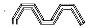
反応管を種々の形態、例えば、波状、メアンダ状、また混合を促進する、ギザギザ状、鋸刃状もしくはジグザグ状の形態でマイクロリアクタパーツにはめ込むことができる(図16a〜16fを参照されたい)。反応管はマイクロリアクタパーツの溝状の凹部に挿入される。溝状の凹部は、その内部に熱伝達媒体を案内するか、管を誘導加熱するための誘導コイルのような他の加熱材料を収容することに適している。誘導コイルを備えた実施形態は殊に有利である。何故ならば、そのような誘導コイルを用いることにより、選択された管または管領域における殊に高い温度を調整することができるからである。このために、有利には管の周囲に巻き付けられるように配置されている慣用の誘導コイル、例えば高周波コイルを使用することができる。 The reaction tube can be fitted into the microreactor part in a variety of forms, such as undulating, meandering, and jagged, sawtooth or zigzag forms that facilitate mixing (see FIGS. 16a-16f). The reaction tube is inserted into the groove-shaped recess of the microreactor part. The groove-like recess is suitable for guiding other heat materials such as an induction coil for guiding the heat transfer medium therein or for inductively heating the tube. Embodiments with induction coils are particularly advantageous. This is because by using such induction coils, particularly high temperatures in the selected tube or tube region can be adjusted. For this purpose, it is possible to use conventional induction coils, for example high-frequency coils, which are preferably arranged to be wound around the tube.
別の態様においては、本発明は、少なくとも2つのマイクロリアクタパーツを備えたマイクロリアクタに関する。マイクロリアクタパーツはそれぞれ、1つのプレート面に溝状の凹部を有するプレートボディを備えており、この凹部には反応管が収容されており、また反応管はそれぞれのプレートボディの外面に接続端部を有する。異なるマイクロリアクタパーツの反応管は接続端部と接続エレメントを介して接続されている。 In another aspect, the invention relates to a microreactor comprising at least two microreactor parts. Each microreactor part has a plate body having a groove-shaped recess on one plate surface, and a reaction tube is accommodated in the recess, and the reaction tube has a connection end on the outer surface of each plate body. Have. The reaction tubes of different microreactor parts are connected to the connection end via connection elements.
接続エレメントは有利には接続ブロックであり、それらの接続ブロックは簡単にモジュール式に反応部品の外面に取り付けることができる。マイクロリアクタパーツの凹部内には、反応性生成物を管理するための管が使用される。一方の端部には、ケーシングプレートを通り抜ける貫通部が設けられており、この貫通部を通して反応管を押し込むことができ、またシーリングを介して、例えば接続ブロックの形態の反応管接続エレメント内に突出させることができる。接続エレメントは偏向部および後続の管との接続部としてのみ機能することができるが、接続エレメントを供給個所、混合個所または生成物取り出し部としても構成することができる。この配置構成によって、反応および反応時間要求に応じて、反応管を適合された接続ブロックを用いて、または相応の管接続部を用いて迂回させることができ、これによってフレキシビリティおよびモジュール化度が高まる。接続エレメントの材料は、鋼、特殊鋼、セラミック、燒結金属、アルミニウム、プラスチック材料、非鉄金属、貴金属でよい。さらに接続エレメントは冷却媒体または加熱媒体を流入および流出させるための複数の孔を有することができる。 The connection elements are preferably connection blocks, which can easily be mounted on the outer surface of the reaction component in a modular manner. A tube for managing the reactive product is used in the recess of the microreactor part. One end is provided with a penetration that passes through the casing plate, through which the reaction tube can be pushed, and projects into the reaction tube connection element, for example in the form of a connection block, via a sealing. Can be made. The connection element can only function as a connection with the deflection part and the subsequent tube, but it can also be configured as a supply point, a mixing point or a product take-out part. With this arrangement, depending on the reaction and reaction time requirements, the reaction tubes can be bypassed with a suitable connection block or with a corresponding tube connection, which increases flexibility and modularity. Rise. The material of the connecting element may be steel, special steel, ceramic, sintered metal, aluminum, plastic material, non-ferrous metal or precious metal. In addition, the connecting element can have a plurality of holes for inflow and outflow of the cooling medium or the heating medium.
有利には、マイクロリアクタのマイクロリアクタパーツは上述のように定義されている。殊に有利には、マイクロリアクタは少なくとも2つ、またはそれ以上の本発明によるマイクロリアクタパーツを含む。 Advantageously, the microreactor parts of the microreactor are defined as described above. Particularly advantageously, the microreactor comprises at least two or more microreactor parts according to the invention.
特定の実施形態においては、1つのマイクロリアクタパーツの反応管、有利には全てのマイクロリアクタパーツの反応管が少なくとも2つの接続端部を有し、これらの接続端部はいずれもそれぞれのリアクタブロックのプレートボディの外面において終端している。プレートボディの同一の外面において終端している接続端部は相互にモジュール式に簡単に接続することができ、殊に、プレートボディに形状が合致するように接合させることができる接続ブロックのような上述の接続エレメントによって接続することができる。 In a particular embodiment, the reaction tubes of one microreactor part, preferably all the reaction tubes of all microreactor parts, have at least two connection ends, each of which is a plate of the respective reactor block Terminates on the outer surface of the body. Connection ends that terminate on the same outer surface of the plate body can be easily connected to each other in a modular manner, in particular such as a connection block that can be joined to the plate body to match the shape. It can be connected by the connection element described above.
別の実施形態においては、反応管を接続エレメントによって接続することができる。接続エレメントは選択的に、反応流体の反応管への流入部または反応管からの流出部、および/または、溝状の凹部によって形成されるチャネルへの流体の流入部またはチャネルからの流出部を含む。一般的に、種々のマイクロリアクタパーツの反応管をプラグエレメント、管またはチューブによって接続することができる。 In another embodiment, the reaction tubes can be connected by connecting elements. The connecting element optionally has an influx of reaction fluid into or out of the reaction tube and / or an inflow of fluid into or out of the channel formed by the groove-like recess. Including. In general, the reaction tubes of the various microreactor parts can be connected by plug elements, tubes or tubes.
本発明によるモジュール式マイクロリアクタは、凹部内を流れる熱伝達媒体によって種々のマイクロリアクタパーツが種々に加熱または冷却される場合には、種々の順序で温度レベルを表すことができる種々のマイクロリアクタパーツを収容することができる。したがって有利には、個々のマイクロリアクタパーツ間に熱絶縁素子が設けられる。その種の熱絶縁素子は例えば、間隔をあけるために2つのプレート間において緊張される個々の絶縁物体または絶縁材料からなるプレートでよい。 The modular microreactor according to the present invention accommodates various microreactor parts that can represent temperature levels in various orders when the various microreactor parts are variously heated or cooled by the heat transfer medium flowing in the recesses. be able to. Thus, advantageously, a thermal insulation element is provided between the individual microreactor parts. Such a thermal insulation element may be, for example, a plate made of individual insulating objects or materials that are tensioned between two plates in order to be spaced apart.
別の態様においては、本発明は、マイクロリアクタを製造するためのキットに関する。マイクロリアクタは有利には、マイクロリアクタパーツ、有利には上記において定義したような少なくとも2つのマイクロリアクタパーツを有し、また有利にはマイクロリアクタパーツの反応管を接続するための接続エレメントを有する。また本発明は、マイクロリアクタパーツを組み合わせることによって、また必要に応じて反応管を接続することによって、マイクロリアクタを製造するための方法に関する。キットは殊に、個々のマイクロリアクタパーツを位置決めするための固定エレメント、例えば固定部材、タイロッドおよびロッキングクランプを含む。さらには、温度管理媒体を供給する個々のチューブを循環のために溝状の凹部に設けることができる。 In another aspect, the invention relates to a kit for manufacturing a microreactor. The microreactor preferably has a microreactor part, preferably at least two microreactor parts as defined above, and preferably also has a connecting element for connecting the reaction tubes of the microreactor part. The invention also relates to a method for producing a microreactor by combining microreactor parts and connecting reaction tubes as required. The kit in particular includes fixing elements for positioning individual microreactor parts, such as fixing members, tie rods and locking clamps. Furthermore, individual tubes for supplying the temperature control medium can be provided in the groove-like recesses for circulation.
本発明の別の態様は、上述したようなマイクロリアクタパーツ、反応管もしくは反応管内で2つの流体を混合するためのマイクロリアクタの使用に関する。上述したように、殊に有利には、断面狭窄部、例えば折り曲げによるノッチを有する本発明による反応管が使用され、これにより一方では管を流れる流体の乱流が高まり、また他方では流体が非対称的に偏向される。したがって殊に有利には、流体がエマルションまたはディスパージョンを形成する。さもなければ、流体を例えば物理的には混合することができない。別の実施形態によれば、有利には、本発明によるマイクロリアクタパーツ、反応管またはリアクタの使用によって混合が行われ、これにより2つの流体の化学反応が行われる。もちろん、2つより多くの流体を使用することもでき、例えばマイクロリアクタに応じて、先ず2つの流体が混合され、次に第3の流体の供給によって、その第3の流体が混合され、この過程を繰り返すことにより、他の流体も同様に混合することができる。流体として反応物が使用されるが、反応停止剤も使用される。有利には、少なくとも2つのマイクロリアクタパーツを備えたマイクロリアクタが使用され、有利には、マイクロリアクタパーツの反応管が溝状の凹部内に流れる熱伝達媒体、有利には水によって種々の温度に加熱または冷却される。 Another aspect of the invention relates to the use of a microreactor for mixing two fluids in a microreactor part, reaction tube or reaction tube as described above. As mentioned above, it is particularly advantageous to use a reaction tube according to the invention with a cross-sectional constriction, for example a notch by bending, which increases on the one hand the turbulence of the fluid flowing through the tube and on the other hand the fluid is asymmetric. Biased. It is therefore particularly advantageous for the fluid to form an emulsion or dispersion. Otherwise, the fluid cannot be physically mixed, for example. According to another embodiment, the mixing is advantageously effected by the use of microreactor parts, reaction tubes or reactors according to the invention, whereby the chemical reaction of the two fluids takes place. Of course, more than two fluids can also be used, for example, depending on the microreactor, first the two fluids are mixed and then the third fluid is mixed by the supply of the third fluid, this process By repeating the above, other fluids can be mixed in the same manner. A reactant is used as the fluid, but a reaction terminator is also used. Preferably, a microreactor with at least two microreactor parts is used, advantageously the reaction tubes of the microreactor parts are heated or cooled to different temperatures by means of a heat transfer medium, preferably water, which flows into the groove-like recess. Is done.
熱伝達媒体は例えば加熱流体または冷却流体であり、例えば液体、蒸気または気体でよい。熱伝達媒体を、並流、向流、交差流で、反応管内を流れる流体ないし反応混合物へと案内することができる。熱伝達媒体を個々のプレートボディそれぞれに供給することができ、また個々のプレートボディから排出することができるか、連続的もしくは並行的に供給することができる。 The heat transfer medium is, for example, a heating fluid or a cooling fluid, and may be, for example, a liquid, a vapor or a gas. The heat transfer medium can be guided in cocurrent, countercurrent or crossflow into the fluid or reaction mixture flowing in the reaction tube. The heat transfer medium can be supplied to each individual plate body and can be discharged from the individual plate bodies or can be supplied continuously or in parallel.
付加的に組み合わせ可能な実施形態もしくは代替的な実施形態においては、溝状の凹部内に、管ないし管領域を加熱するための1つまたは複数の誘導コイルが使用される。誘導的な加熱によって、200℃〜600℃以上の温度管理が実現される。したがって、このことは高温反応にとって殊に有利である。誘導的な加熱のために、誘導コイルを除いて、溝状の凹部内に有利には液体が存在しない。管との間に隙間が存在する場合には、凹部を気体で充填することができるか、真空にすることもできるか、誘導コイルおよび反応管の形状に適合するよう設計することができる。 In an additionally combinable or alternative embodiment, one or more induction coils for heating the tube or tube region are used in the groove-like recess. By inductive heating, temperature control of 200 ° C. to 600 ° C. or more is realized. This is therefore particularly advantageous for high temperature reactions. Due to the inductive heating, there is advantageously no liquid in the groove-like recess, except for the induction coil. If there is a gap with the tube, the recess can be filled with gas, can be evacuated, or designed to fit the shape of the induction coil and reaction tube.
有利には、2つの流体の混合個所においては、これら2つの気体が異なる速度で、有利には少なくとも2倍、有利には少なくとも3倍、殊に少なくとも4倍の速度差で混合される。これによって、2つの流体の拡散が生じ、したがって効率的な混合が行われる。 Preferably, at the mixing point of the two fluids, the two gases are mixed at different speeds, preferably at least twice, preferably at least three times, in particular at least four times the speed difference. This causes the diffusion of the two fluids, thus providing efficient mixing.
また有利には、混合個所において2つの流体が140°〜220°、有利には160°〜200°、殊に有利には180°の角度で相互に衝突する。この角度は2つの流体の上述の拡散を促進する。混合すべき2つの流体の流入管に対して、例えば90°ずらして、流体をさらに流すことができる。マイクロリアクタパーツ内の反応管を既に通過した流体を反応管に供給することができ、また、第2の流体を接続エレメントにおける流入部を通してさらに供給することができる。この場合、混合物はマイクロリアクタパーツ内の別の反応管へとさらに供給される。混合個所における2つの流体の速度を、混合ノズルの圧力および断面によって、有利には所定数の孔を備えた孔プレートを選択することによって調整することができる。例えば一定の開口断面を備えた所定数の孔によって調整されており、また所定数の開口断面を備えている、事前に製造された所定の孔プレートによって、本発明によるモジュール式のマイクロリアクタを所定の用途および流量に関して調整することができる。 Also preferably, the two fluids impinge on each other at an angle of 140 ° to 220 °, preferably 160 ° to 200 °, particularly preferably 180 ° at the mixing point. This angle facilitates the aforementioned diffusion of the two fluids. The fluid can be further flowed, for example, shifted by 90 ° with respect to the two fluid inlet pipes to be mixed. The fluid that has already passed through the reaction tube in the microreactor part can be supplied to the reaction tube, and the second fluid can be further supplied through the inlet in the connecting element. In this case, the mixture is further fed to another reaction tube in the microreactor part. The speed of the two fluids at the mixing point can be adjusted by the pressure and cross-section of the mixing nozzle, preferably by selecting a hole plate with a predetermined number of holes. For example, a modular microreactor according to the present invention is pre-determined by means of a pre-made pre-made hole plate that is regulated by a pre-determined number of holes with a constant open cross-section and with a pre-determined number of open cross-sections It can be adjusted for application and flow rate.
マイクロリアクタの管は高圧リアクタにも適しており、また例えば流体の入口圧力の値を少なくとも1bar、少なくとも5bar、有利には少なくとも8bar、殊に有利には少なくとも10barとすることができる。しかしながらこれらの例示した圧力値は制限を意図したものではなく、単に有利な例として挙げたものに過ぎない。流体の入口圧力を、管または(乱流および渦流のための)流れ遮断器の幾何学、個数に応じて、またそれと結び付く圧力損失に応じて選択することができる。有利には、リアクタの圧力損失(0〜160bar)を形成することができる、(体積または流量に関して)適切な供給手段が使用される。 The tubes of the microreactor are also suitable for high-pressure reactors, and for example, the inlet pressure value of the fluid can be at least 1 bar, preferably at least 5 bar, preferably at least 8 bar, particularly preferably at least 10 bar. However, these illustrated pressure values are not intended to be limiting and are merely given as advantageous examples. The inlet pressure of the fluid can be selected depending on the geometry, number of flow interrupters (for turbulence and vortex flow) and the pressure loss associated therewith. Advantageously, suitable supply means (in terms of volume or flow rate) are used that can form a pressure drop (0-160 bar) in the reactor.
有利には、反応管内を流れる流体のうちの一方が液体であり、反応管内で第1の流体と混合される他方の流体は液体、気体または超臨界流体である。本発明によれば、種々の流体を任意に組み合わせることができる。例えば、液体と液体の混合物、気体と液体の混合物、気体と超臨界流体の混合物、または、液体と超臨界流体の混合物を供給ないし混合することができる。同様に、液体、気体または超臨界流体を渦流化または流動化された固体粒子と混合させることもできる。流動化された固体粒子は例えば、化学反応に使用される触媒粒子である。 Advantageously, one of the fluids flowing in the reaction tube is a liquid and the other fluid mixed with the first fluid in the reaction tube is a liquid, a gas or a supercritical fluid. According to the present invention, various fluids can be arbitrarily combined. For example, a liquid-liquid mixture, a gas-liquid mixture, a gas-supercritical fluid mixture, or a liquid-supercritical fluid mixture can be supplied or mixed. Similarly, a liquid, gas or supercritical fluid can be mixed with vortexed or fluidized solid particles. The fluidized solid particles are, for example, catalyst particles used for chemical reaction.
有利には、本発明は以下のように定義される。 Advantageously, the invention is defined as follows.
1.1つのプレート面に反応管が収容されている溝状の凹部を有するプレートボディを備え、反応管はプレートボディの外面に接続端部を有する、マイクロリアクタパーツ。 1. A microreactor part comprising a plate body having a groove-like recess in which a reaction tube is accommodated on one plate surface, and the reaction tube has a connection end on the outer surface of the plate body.
2.プレートボディは平行六面体の形状を有している、定義1のマイクロリアクタパーツ。
2. The microreactor part defined in
3.凹部は反応管の周囲にチャネルを形成する、定義1または2のマイクロリアクタパーツ。
3. A microreactor part of
4.反応管は外面におけるシーリング素子において終端しており、シーリング素子は有利には凹部も閉じる、定義1から3のいずれか1つのマイクロリアクタパーツ。
4). The microreactor part of any one of
5.プレート面における凹部は別のプレートによってシーリングされている、定義1から4のいずれか1つのマイクロリアクタパーツ。
5. The microreactor part of any one of
6.プレートボディのプレートフレームに沿ってシーリング、有利にはプラスチックシーリングが収容されている、定義1から5のいずれか1つのマイクロリアクタパーツ。
6). A microreactor part according to any one of
7.プレートボディはプレートまたは別のマイクロリアクタパーツを1つのプレート面に固定するための固定エレメント、ないし固定エレメントのアダプタ、有利にはタイロッドのためのノッチを有する、定義1から6のいずれかのマイクロリアクタパーツ。
7). A microreactor part according to any of
8.反応管は管の概形において、有利には折り曲げによって形成された、管断面の一方の側において断面積の少なくとも20%の断面狭窄部、および/または、断面拡張部を有する、定義1から7のいずれか1つのマイクロリアクタパーツ。
8). The reaction tube has a cross-sectional constriction and / or a cross-sectional extension of at least 20% of the cross-sectional area on one side of the cross-section of the tube, preferably by bending, in the general shape of the tube,
9.プレートは少なくとも2つの反応管を有し、有利には、必要に応じてメアンダ状である、同一の溝状の凹部内に少なくとも2つの反応管を有する、定義1から8のいずれか1つのマイクロリアクタパーツ。
9. The microreactor of any one of
10.2つの反応管のプレートボディの外面において、接続エレメント(管コネクタ)を介して接続端部が接続されている、定義9のマイクロリアクタパーツ。
10. A microreactor part as defined in
11.少なくとも1つの接続エレメントは流体流入部または流体流出部を有する、定義10のマイクロリアクタパーツ。
11. The microreactor part of
12.溝状の凹部はメアンダ状の概形を有し、概形のメアンダ状の領域の間には間仕切壁が設けられており、間仕切壁は有利には、プレートボディのプレートフレームと共に1つのプレートによってシーリングされている、定義9から11までのいずれかのマイクロリアクタパーツ。
12 The groove-like recess has a meander-like outline, and a partition wall is provided between the roughly meander-shaped regions, and the partition wall is advantageously formed by one plate together with the plate frame of the plate body. Any microreactor part from
13.反応管の接続端部またはプラグエレメントの流体流入部または流体流出部は流体混合器を有する、定義1から12のいずれか1つのマイクロリアクタパーツ。
13. The microreactor part of any one of
14.流体混合器は、流れ遮断器、流れ加速器、混合ノズルまたは注入ニードルである、定義13のマイクロリアクタパーツ。
14 The microreactor part of
15.反応管内または接続端部において、センサ、殊に温度センサ、有利にはサーモスタットと接続されたセンサ、または光学センサ、または屈折率センサ、有利には測定プリズムを備えた屈折率センサが取り付けられている、定義1から14までのいずれかのマイクロリアクタパーツ。
15. Mounted in the reaction tube or at the connection end is a sensor, in particular a temperature sensor, preferably a sensor connected to a thermostat, or an optical sensor, or a refractive index sensor, preferably a refractive index sensor with a measuring prism. , Any microreactor part from
16.反応管の接続端部は加圧制御器、有利には圧力開放弁、ブローアウトディスクまたは栓と接続されている、定義1から15までのいずれかのマイクロリアクタパーツ。
16. A microreactor part according to any of the
17.反応管は金属、セラミックまたはプラスチックから構成されている、定義1から16のいずれか1つのマイクロリアクタパーツ。
17. A microreactor part according to any one of
18.混合エレメントとしての断面狭窄部を備えた反応管であって、断面は、管、有利には円形の管の一方の側において少なくとも15%、有利には少なくとも20%狭められている、反応管。 18. Reaction tube with a constriction as a mixing element, the cross-section being narrowed at least 15%, preferably at least 20% on one side of the tube, preferably a circular tube.
19.管の断面は狭窄部の向かい側では拡張されておらず、有利には狭窄部に対して90°の位置においても拡張されておらず、有利には狭窄部の向かい側の断面は半円を形成する、定義18の反応管。
19. The cross section of the tube is not expanded opposite the stenosis, and is preferably not expanded at a 90 ° position relative to the stenosis, and preferably the cross section opposite the stenosis forms a semicircle.
20.複数の断面狭窄部を有し、有利には断面狭窄部が設けられる側が交互に現れ、殊に断面狭窄部は螺旋状にずらされているか、管断面において対向するようずらされている、および/または、断面狭窄部は有利には直線状、角柱状、円筒状または球状である、定義18または19の反応管。
20. Having a plurality of cross-section constrictions, preferably the sides where the cross-section constrictions are provided appear alternately, in particular the cross-section constrictions are displaced in a helical manner or in opposition in the tube cross section, and / or Alternatively, the reaction tube of
21.管の全長の少なくとも10%は断面狭窄部を有する、定義18から20のいずれかの反応管。この反応管は有利にはマイクロリアクタパーツに使用される。
21. Reaction tube according to any of
22.少なくとも2つのマイクロリアクタパーツを備えたマイクロリアクタであって、マイクロリアクタパーツはそれぞれ、1つのプレート面に溝状の凹部を有するプレートボディを備えており、凹部には反応管が収容されており、また反応管はそれぞれのプレートボディの外面に接続端部を有し、異なるマイクロリアクタパーツの反応管は接続端部と接続エレメントを介して接続されている、マイクロリアクタ。 22. A microreactor including at least two microreactor parts, each microreactor part having a plate body having a groove-like recess on one plate surface, and a reaction tube is accommodated in the recess, and the reaction tube Each has a connection end on the outer surface of each plate body, and the reaction tubes of different microreactor parts are connected to the connection end via a connection element.
23.マイクロリアクタパーツのうちの少なくとも1つ、有利には少なくとも2つは定義1から17までのいずれかのものである、定義22のマイクロリアクタ。
23. A microreactor according to
24.1つのマイクロリアクタパーツの反応管、有利には全てのマイクロリアクタパーツの反応管が接続端部を有し、接続端部はいずれもそれぞれのリアクタブロックのプレートボディの外面において終端している、定義22または23のマイクロリアクタ。
24. Definition of a reaction tube of one microreactor part, preferably all reaction tubes of all microreactor parts, having a connection end, each of which ends on the outer surface of the plate body of the
25.反応管は接続エレメントによって接続されており、接続エレメントは選択的に、反応流体の反応管への流入部または反応管からの流出部、および/または、凹部のチャネルへの流体の流入部またはチャネルからの流出部を含む、定義22から24のいずれかのマイクロリアクタ。
25. The reaction tubes are connected by a connection element, which is optionally connected to the inflow or outflow from the reaction tube of the reaction fluid and / or the inflow or channel of fluid into the channel of the recess A microreactor of any of
26.異なるマイクロリアクタパーツの反応管はプラグエレメント、管またはチューブによって接続されている、定義22から25のいずれか1つのマイクロリアクタ。
26. The microreactor of any one of
27.2つのマイクロリアクタパーツ間に熱絶縁素子が設けられている、定義22から26のいずれかのマイクロリアクタ。
27. A microreactor according to any of
28.定義1から17までのいずれかのマイクロリアクタパーツ、有利には少なくとも2つのマイクロリアクタパーツと、有利には、マイクロリアクタパーツをマイクロリアクタに接続するための接続エレメントとを含む、定義22から27のいずれかのマイクロリアクタを製造するキット。
28. A microreactor of any of
28.反応管において2つの流体を混合するための、定義1から17までのいずれかのマイクロリアクタパーツの使用、または定義18から21までのいずれかの反応管の使用、または定義22から27までのいずれかのマイクロリアクタの使用。
28. Either the use of any microreactor part from
29.2つの流体はエマルションまたはディスパージョンを形成する、定義28の使用。
29. Use of
30.付加的に、2つの流体の化学反応を生じさせる、定義27または28の使用。
30. In addition, use of
31.少なくとも2つのマイクロリアクタパーツを備えたマイクロリアクタを使用し、有利には、溝状の凹部内に流れる熱伝達媒体、有利には水によってマイクロリアクタパーツの反応管を種々の温度に加熱または冷却する、定義28から30までのいずれかの使用。
31. A microreactor with at least two microreactor parts is used, advantageously heating or cooling the reaction tubes of the microreactor parts to various temperatures by means of a heat transfer medium, preferably water, flowing in the groove-like recesses,
32.熱伝達媒体を向流または並流で反応管内の反応混合物へと案内する、定義31の使用。
32. Use of
33.2つの流体の混合個所において、2つの気体を異なる速度で、有利には少なくとも2倍、有利には少なくとも3倍、殊に少なくとも4倍の速度差で混合する、定義28から32までのいずれかの使用。
33.
34.2つの流体の混合個所において、2つの流体が140°〜220°、有利には160°〜200°、殊に有利には180°の角度で相互に衝突する、定義28から33のいずれかの使用。
34. Any of
35.混合個所において、2つの流体の速度を、混合ノズルの圧力および断面によって、有利には所定数の孔を備えた孔プレートを選択することによって調整する、定義28から34のいずれかの使用。
35. Use of any of
36.流体の入口圧力の値は少なくとも1bar、有利には少なくとも5bar、殊に有利には少なくとも10barである、定義28から35のいずれかの使用。
36. Use of any of
37.流体のうちの一方の流体は液体であり、他方の流体は液体、気体または超臨界流体である、定義28から36のいずれかの使用。
37. Use of any of
以下では、本発明を添付の図面および実施例に基づき詳細に説明するが、それらは本発明を制限することを意図したものではない。 In the following, the present invention will be described in detail with reference to the accompanying drawings and examples, which are not intended to limit the present invention.
実施例:
実施例1:構造の説明
マイクロリアクタはモジュール構造を特徴としており、これによって滞留時間などのパラメータを種々の反応に適合させることができる。
Example:
Example 1: Structural Description The microreactor features a modular structure, which allows parameters such as residence time to be adapted to various reactions.
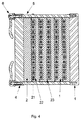
モジュールプレートないしマイクロリアクタパーツ1はプレートボディから構成されており、このプレートボディにおいて反応管21が凹部22に案内される。反応管21はU字型の取付具24によって凹部22に固定される。管には前面から反応媒体が供給される。プレートボディ1内の凹部は、反応に必要とされる温度を調整するための冷却流体ないし加熱流体のための誘導路として使用される。マイクロリアクタは熱交換器のように構成されており、冷却処理ないし加熱処理を並流においても向流においても実施することができる。加熱媒体用の供給9,10はプレートボディの左側および右側において行われる。複数の孔が凹部の最も高い場所にあり、それによって場合によっては空気を逃すことができるように接続部を実施することができる。前面には管コネクタ20が取り付けられており、それらの管コネクタ20をフレキシブルに位置決めすることができる。管状固定具8の使用によって、管の長さを個別的に反応に適合させることができる。管状固定具8は個々のモジュール間の接続部としても使用される。
The module plate or
例えば、マイクロリアクタを複数の段階での複数の反応物質の反応のために設けることができる。例えば:
1.反応媒体の反応温度への加熱(第1モジュール)
2.媒体の反応(第2モジュール〜第4モジュール)
3.溶液の稀釈および反応の停止(第5モジュール)
For example, a microreactor can be provided for reaction of multiple reactants at multiple stages. For example:
1. Heating reaction medium to reaction temperature (first module)
2. Medium reaction (2nd to 4th modules)
3. Dilution of solution and termination of reaction (5th module)
個々の反応管部分またはマイクロリアクタパーツは個別のモジュールを表す。 Individual reaction tube sections or microreactor parts represent individual modules.
第1モジュールから第4モジュールは同じ温度レベルで動作するので、それらのモジュールは1つの機能的レベル内にある。別の温度レベルが存在する場合、第5モジュールは第4モジュールに直接的に接していない。スペーサ3および絶縁プレート2によって空間的に隔てることができる。
Since the first to fourth modules operate at the same temperature level, they are within one functional level. When another temperature level is present, the fifth module is not in direct contact with the fourth module. It can be spatially separated by the
図1によるリアクタの特定の実施形態においては、個々のマイクロリアクタパーツ1ないしモジュールの構造が例示的に示されており、それらのマイクロリアクタパーツ1ないしモジュールを例えばカバーモジュール2ないし絶縁体3によって隔てることができる。個々のマイクロリアクタパーツおよびプレート絶縁体は固定部材4によって保持され、それらの固定部材4はタイロッド5およびロッキングクランプ6によって固定される。リアクタの下方には、フォークリフトのアタッチメント受容部の形態の脚部7が設けられている。個々のマイクロリアクタパーツは接続エレメント(プレートコネクタ)8によって接続される。プレートボディ内の個々の反応管は、例えば、接続ブロック20の形態の管接続エレメントによって接続される。個々のプレートは冷却媒体の流入部ないし流出部9もしくは加熱媒体の流入部ないし流出部10を有することができる。熱媒体としてのそれらの冷却媒体ないし加熱媒体は凹部22においてプレートを通って案内される。
In the particular embodiment of the reactor according to FIG. 1, the structure of the
マイクロリアクタは複数の反応媒体入口および出口を有することができる。例えば、流体A用の入口11、流体B用の入口12、混合物A/B用の出口13、反応流体C用の入口14、別のプレートにおける反応混合物A/B用の入口15;択一的に、混合物A/B/C用の出口(ここでは自由な接続端部16)、別のプレートにおける混合物A/B/C用の入口17、反応媒体D用の入口18および生成物出口19を有することができる。
The microreactor can have multiple reaction medium inlets and outlets. For example, an
図2は、6つの異なるプレートボディ1を備えたリアクタの概略的な側面図を示し、また断面C(図3を参照されたい)および断面B(図4を参照されたい)も示唆されている。
FIG. 2 shows a schematic side view of a reactor with six
図3は、プレートの複数の管を接続するための種々の接続エレメント(管コネクタ)20の断面図を示す。個々のプレートはプレートコネクタ8によって接続されている。
FIG. 3 shows a cross-sectional view of various connection elements (tube connectors) 20 for connecting a plurality of tubes of the plate. The individual plates are connected by a
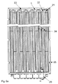
図4によれば、5つの異なるプレートから成るリアクタの断面図が示されており、反応管21が溝状の凹部22内にどのように挿入されているかが図示されている。個々のプレートをシール23によってシーリングすることができる。
FIG. 4 shows a cross-sectional view of a reactor consisting of five different plates, illustrating how the
図5aから見て取れるように、凹部内の個々の管を取付具24によって固定することができる。タイロッド5によって個々のプレートを固定するために、タイロッド5を固定するためのノッチ25が設けられている。図5bは、付加的に、モジュールの供給/流出個所11、流入個所12、流出個所13、混合物流入個所13bおよびモジュールの供給/流出個所11bを示す。さらに、熱媒体入口22bないし熱媒体出口22aも示されている。
As can be seen from FIG. 5 a, the individual tubes in the recess can be fixed by means of a
図6は、接続エレメントがプレートボディ1にどのように取り付けられているかを表す、接続エレメントを側方から見た断面図を示す。ここでは管21の接続部材が設けられており、この接続部材を別の管の奥の方にまで案内することもできる。接続エレメントは接続ブロック26として示されており、この接続ブロック26は、プレートの反応管21内に突出している管27を有する。この管27は分配素子30によってシールされている。分配素子30内には複数の孔が設けられているので、流体を種々の方向(角度)からリアクタに供給することができる。個々の接続個所はシール28,29によってシーリングされており、これらは張力シール28または圧力シール29として構成することができる。
FIG. 6 shows a cross-sectional view of the connecting element from the side, showing how the connecting element is attached to the
図7aは、断面狭窄部31ないし断面拡張部32を有する反応管21を示す。これらの断面狭窄部31ないし断面拡張部32は有利には規則的な間隔a、例えば50mmの間隔aを空けて設けられている。図7bは、円形ないし球状の断面狭窄部を有する反応管を示す。また図7cは、円形の断面拡張部と、反応管の断面に対して傾斜した角度で設けられた斜めの断面狭窄部を有する反応管を示す。
FIG. 7 a shows a
図8は、内径i(例えば5mm)と外径a(例えば6mm)と断面狭窄部b(例えば1.51mm)とを有する断面狭窄部の断面図を示す。もちろん、断面狭窄部に関しては他の寸法で構成することもできる。 FIG. 8 shows a cross-sectional view of a cross-section constriction having an inner diameter i (for example, 5 mm), an outer diameter a (for example, 6 mm), and a cross-section constriction b (for example, 1.51 mm). Of course, the cross-sectionally narrowed portion can be configured with other dimensions.
図9には、管21を接続する接続エレメント20が示されている。付加的に、流入個所ないし流出個所34が設けられている。管21ならびに流入個所34は、穴開きディスクとして実施されている混合ノズル33を介して、共通のチャネルおよび隣接する管35内の流入個所へと案内される。
FIG. 9 shows a
図10には流入個所40が示されている。この図10では、流入管41の上方に接続ブロック素子37を介するインジェクションランス43が示されており、このインジェクションランス43はセンタリング部材43bによって閉じられており、また種々の孔を介して管21へと案内されている。複数の孔を使用することによって、流入する流体は種々の個所において連続的に管21に案内される。管21は直接的に別の接続管42へと案内されている。熱媒体が存在する凹部22を、流出個所36を介して隣に位置する管と接続することができる。もしくは熱媒体が存在する凹部22に流出個所36を介して熱媒体を流入ないし流出させることができる。管21はブシュ39およびナット38によって固定される。
FIG. 10 shows the
図11には、3つの異なるプラグエレメントa),b),c)が示されており、これらのプラグエレメントは、管21間の簡単なプラグ接続部として実施されている。プラグエレメントb)の実施形態によれば、付加的に流体流入個所ないし流体流出個所もプラグエレメント20内に設けられている。図11に示されているプラグエレメントc)の実施形態によれば、プラグエレメント20bは接続エレメントとして実施されておらず、隣接する2つの管の流入部ないし流出部として実施されている。
FIG. 11 shows three different plug elements a), b), c), which are implemented as simple plug connections between the
図12には、図1に示したマイクロリアクタの前面および側面が示されている。 FIG. 12 shows the front and side surfaces of the microreactor shown in FIG.
図13は個別的に接続されたマイクロリアクタの前面を示し、またマイクロリアクタには位置1〜70が示されている。このマイクロリアクタにおいて、位置1は流体Aの流体流入部(図1における参照番号11に対応)である。位置2において流体Bが供給される。位置3における管は流体A/B混合物の加熱に使用される。位置4はA/B混合物の流出部を示す。位置5は反応媒体Cの流入部を示す。位置6〜12は、流体Cを加熱するための管を示す。すなわち、一番下に位置する第1のモジュールは流体A/BおよびCの並行した加熱に使用される。位置12から位置13へと延びる管から流体Cが第2のモジュールに供給される。位置14においては、流体A/B混合物が第2のモジュールに供給される。位置15〜49の管は流体A/B/Cの化学反応に使用される。位置50において流体Dが供給される。位置51〜59の管は反応に使用されるか、流体Dが反応停止剤である場合には反応の停止に使用され、また温度管理にも使用される。位置60は生成物取出部を示す。位置61〜68において加熱媒体が流入または流出され、また位置68および70において冷却媒体が流入または流出される。
FIG. 13 shows the front face of the individually connected microreactors, and the microreactors are shown in positions 1-70. In this microreactor,
図14には、穴開きディスクの形態の混合ノズルを通り抜けて突出している、4つの異なる注入ニードルの形態の混合ランスが示されている。異なる距離(b1,b2,b3)でもって注入ニードルが段状にずらされることによって、種々の混合領域を制御することができる。 FIG. 14 shows a mixing lance in the form of four different injection needles protruding through a mixing nozzle in the form of a perforated disk. By shifting the injection needle in steps with different distances (b1, b2, b3), the various mixing zones can be controlled.
実施例2:動作
供給
図13に示されているように接続されたマイクロリアクタにおける反応に関して、必要とされる化学物質がポンプを介して、第1のモジュール内に設けられている供給個所ないし混合個所に搬送され、それらの個所から化学物質はマイクロリアクタに到達する。
Example 2: Operation Supply For a reaction in a microreactor connected as shown in FIG. 13, the required chemicals are supplied via a pump in a first module or a mixing point. From there, the chemicals reach the microreactor.
供給個所:
流体A 位置1
流体B 位置2(混合個所)
流体C 位置5
流体D 位置50(混合個所)
Supply location:
Fluid A
Fluid B position 2 (mixing location)
Fluid D position 50 (mixing location)
冷却媒体/加熱媒体の供給はポンプを用いて行われ、媒体は長手方向側において、Swagelok社の3/4インチのねじ継手を介して流入され、対向する側(位置61〜70)から流出される。第1モジュールから第4のモジュールは同じ温度レベルで動作するので、それらのモジュールには共通の供給路を介して加熱流体が供給される。温度レベルが異なる場合には、第5のモジュールにおける供給は固有の供給路を介して行われる。
The cooling medium / heating medium is supplied by means of a pump, the medium flowing in on the longitudinal side via a
混合
反応物の混合は向流ミキサにおいて行われ、この向流ミキサにおいては反応物が非常に高速で相互に衝突する。速度の上昇は小型の混合プレートによって達成される。混合された反応物は別の混合プレートを通過して再び反応管へと戻る。
Mixing Mixing of the reactants takes place in a countercurrent mixer, in which the reactants collide with each other at a very high speed. The speed increase is achieved by a small mixing plate. The mixed reactant passes through another mixing plate and returns to the reaction tube.
混合個所は以下の位置に設けられている:
混合個所1 位置2
混合個所2 位置14
混合個所3 位置50
The mixing points are located at the following locations:
Mixing
Mixing
Mixing
反応
反応は位置14において流体Cが向流ミキサによって流体A/B混合物に混ぜられることによって開始される。必要な滞留時間は管ないしモジュールの数を介して調整することができる。
Reaction The reaction is initiated at
稀釈
位置50における流体Dの付加に基づき、稀釈および温度変化によって反応が停止する。ここでもまた、2つの流れの混合は向流ミキサにおいて行われる。
Based on the addition of fluid D at
生成物の取り出し
生成物は位置60において約40℃の温度で取り出される。
Product Removal Product is withdrawn at
装置の開放は、反応空間ないし冷却循環系が先行して空にされた後にのみ行われるべきである。装置を開放するために、ロッキングクランプが解除され、これによって固定ロッドが緩められる。続いて、固定ロッドおよび固定部材をリアクタから取り外すことができる。この時点において個々のモジュールを取り外すことによってリアクタを開放することができる。 The opening of the device should only take place after the reaction space or cooling circulation system has been emptied first. In order to open the device, the locking clamp is released, thereby loosening the fixing rod. Subsequently, the fixing rod and the fixing member can be removed from the reactor. At this point, the reactor can be opened by removing the individual modules.
組立の際にはリアクタモジュールを再び正確に相互に重ね合わせ、モジュールが面一で密に配置されているかを検査する必要がある。 When assembling, it is necessary to accurately superimpose the reactor modules on each other again and to check whether the modules are arranged flush with each other.
続いて、固定ロッド、固定部材およびロッキングクランプがリアクタに取り付けられ、固定ロッドがロッキングクランプを用いて緊張され、続いてレバーが倒される。 Subsequently, the fixing rod, the fixing member and the locking clamp are attached to the reactor, the fixing rod is tensioned using the locking clamp, and then the lever is collapsed.
実施例3:動作値
以下の例では、下記の表1のパラメータ値を言及しつつ、所定の流量および圧力比を例示的に説明する。本発明によるマイクロリアクタには、番号2が付された行に記載された直径を有する反応管を設け、またマイクロリアクタを番号1が付された行に記載されている相応の流量でもって動作させた。番号3が付された行に記載されている特定の表面/体積比はリアクタ設計および幾何学に基づき算出された。
Example 3: Operating Values In the following example, the predetermined flow rate and pressure ratio will be exemplarily described with reference to the parameter values in Table 1 below. The microreactor according to the invention was provided with a reaction tube having the diameter described in the row numbered 2 and the microreactor was operated at the corresponding flow rate described in the row numbered 1. The specific surface / volume ratio listed in the row numbered 3 was calculated based on the reactor design and geometry.

マイクロリアクタには流体Aが位置1において圧力ポンプを用いて供給され、また番号4が付された行に記載されている、第1の反応管における空管速度v1でもって位置2(混合個所)へとさらに移送された。
The microreactor is supplied with fluid A using a pressure pump at
流体Aと流体Bを混合する前に、流体Aは流速の適合のために混合ノズルを介して供給された。 Prior to mixing fluid A and fluid B, fluid A was fed through a mixing nozzle for flow rate adaptation.
混合ノズルによって調整される速度比v2/v1の値は番号11が付された行に記載されている。位置2(混合個所)においては、番号5が付された行に記載されている空管速度(5)でもって流体Bが供給された。第1の空管速度を上昇させるために、流体Bが同様に混合ノズルを介して供給された。混合ノズルによって調整される速度比v2/v1の値は番号12が付された行に記載されている。得られた混合物1は番号6が付された行に記載されている空管速度でもって接続部材を介してさらに移送され、また流速を上昇させるために混合ノズルを介して供給された。混合ノズルによって調整される速度比v2/v1の値は番号13が付された行に記載されている。
The value of the speed ratio v2 / v1 adjusted by the mixing nozzle is described in the row numbered 11. In position 2 (mixing location), fluid B was supplied with the empty pipe velocity (5) described in the row numbered 5. In order to increase the first empty tube speed, fluid B was also fed through the mixing nozzle. The value of the speed ratio v2 / v1 adjusted by the mixing nozzle is described in the row numbered 12. The resulting
流体Cは管の位置5において、番号7が付された行に記載されている空管速度でもって温度管理のために供給され、また(流体Aおよび流体Bから成る)流体混合物1の集中的な混合のために混合個所2(位置14)に供給された。第1の空管速度を上昇させるために、流体Cが同様に混合ノズルを介して供給された。混合ノズルによって調整される速度比v2/v1の値は番号14が付された行に記載されている。得られた流体混合物2は番号8が付された行に記載されている空管速度でもってさらに移送され、また流速を上昇させるために混合ノズルを介して供給された。混合ノズルによって調整される速度比v2/v1の値は番号15が付された行に記載されている。温度管理下で正確に調整された滞留時間が経過すると、得られた混合物2は位置50の手前にある反応位置から反応後に取り出され、混合個所3(位置50)に供給された。流体Dは管の位置50において、番号9が付されている行に記載されている空管速度でもって(流体Aおよび流体Bおよび流体Cから形成された)流体混合物2の集中的な混合のために混合個所3に供給された。番号9が付された行に記載されている第1の空管速度を上昇させるために、流体Dが同様に混合ノズルを介して供給された。混合ノズルによって調整される速度比v2/v1の値は番号16が付された行に記載されている。得られた生成物流体は番号10が付された行に記載されている空管速度でもってさらに移送され、また流速を上昇させるために混合ノズルを介して供給された。混合ノズルによって調整される速度比v2/v1の値は番号16が付された行に記載されている。得られた生成物は複数の混合ノズルを介して、番号17が付された行に記載されている速度に調整されて供給され、温度管理下ないし熱排出下で正確に調整された滞留時間後に、最後のリアクタ部から取り出され、さらなる処理部に供給される。
Fluid C is supplied for temperature management at the
個々の流体、混合物および生成物の体積流/表面のプロセスパラメータは番号18〜22が付された行に記載されている。 The process parameters for the volume flow / surface of the individual fluids, mixtures and products are listed in rows numbered 18-22.
番号23〜25が付された行に記載されている、管内流れから生じるレイノルズ数は80〜22,000の範囲にある。 The Reynolds number resulting from the flow in the tube, described in the rows numbered 23-25, is in the range of 80-22,000.
リアクタ領域にわたる総圧力損失は流量に依存して4〜33barの範囲で推移する。総圧力損失に寄与する、流体および混合物の個々の圧力損失は、総圧力損失の1〜70%の範囲になりうる。 The total pressure loss over the reactor zone varies between 4 and 33 bar depending on the flow rate. The individual pressure losses of fluids and mixtures that contribute to the total pressure loss can range from 1 to 70% of the total pressure loss.
熱伝達処理によって計算されるヌセルト数は流体および混合物ならびに生成物に応じて1〜200の範囲にある。 The Nusselt number calculated by the heat transfer process ranges from 1 to 200 depending on the fluid and the mixture and the product.
実施例4:ニトロトルエンの製造
純トルエン(沸点111℃、密度=0.87g/ml)がマイクロリアクタ(トルエン貯蔵容器)に供給される。安定した硝酸(濃硝酸65重量%、密度=1.40g/ml)ならびに安定した硫酸(濃硫酸95〜98牛量%、密度=1.84g/ml)は、混酸の製造のための別個のサージタンクに供給されている。ニトロトルエン自体についての反応は本発明によるマイクロリアクタにおいて行われ、出発物質は既に準備された貯蔵容器から窒素超過圧力によって個々の供給路を介してマイクロリアクタに供給される。
Example 4 Production of Nitrotoluene Pure toluene (boiling point 111 ° C., density = 0.87 g / ml) is fed to a microreactor (toluene storage container). Stable nitric acid (65% by weight concentrated nitric acid, density = 1.40 g / ml) as well as stable sulfuric acid (95-98% by weight concentrated sulfuric acid, density = 1.84 g / ml) is a separate It is supplied to the surge tank. The reaction for the nitrotoluene itself takes place in the microreactor according to the invention, and the starting material is supplied to the microreactor via individual supply channels by means of nitrogen overpressure from a previously prepared storage vessel.
ニトロトルエンを製造するための反応はマイクロリアクタにおいて行われ、このマイクロリアクタは図1に示したようにモジュール式に構成されており、実質的に2つのゾーン、すなわち反応ゾーンと、下流側の滞留時間および冷却(温度管理)ゾーンとを有する。 The reaction for producing nitrotoluene takes place in a microreactor, which is structured in a modular manner as shown in FIG. 1 and has substantially two zones: a reaction zone, a downstream residence time and cooling. (Temperature control) zone.
マイクロリアクタの反応ゾーンの温度は、反応管を流れる反応物質が約5〜10℃に保持されるように管理される。 The temperature of the reaction zone of the microreactor is controlled so that the reactant flowing through the reaction tube is maintained at about 5-10 ° C.
この温度管理は、有利には、冷却流体(冷却オイルまたは他の熱媒体)を反応管に当てることにより、管の外側からの間接的な制御による熱除去によって行われる。 This temperature management is advantageously performed by heat removal by indirect control from the outside of the tube by applying a cooling fluid (cooling oil or other heat medium) to the reaction tube.
下流側の滞留時間および冷却ゾーンにおいては反応混合物を約2℃〜6℃に温度管理ないし冷却することができる。 In the downstream residence time and cooling zone, the reaction mixture can be temperature controlled or cooled to about 2 ° C to 6 ° C.
反応制御
冷たい温度に管理されたマイクロリアクタパーツにおいては、トルエンの混合物の供給ならびに混酸(硝酸および硫酸)の製造が行われる。
Reaction control In a microreactor part controlled at a cold temperature, a mixture of toluene and a mixed acid (nitric acid and sulfuric acid) are produced.
混酸を製造するためのマイクロリアクタの反応セクションは、プロセスの観点において、混酸の温度が5℃を上回らないように設計されることが望ましい。したがって、固有のマイクロリアクタセクションにおいては、先ず濃硝酸と濃硫酸とが、図6,9および10に示されているようなノズル注入系および混合系を介して混合され、また混合過程中に即座に管内では図9の位置35において冷却される。
The reaction section of the microreactor for producing the mixed acid is desirably designed so that the temperature of the mixed acid does not exceed 5 ° C. from the viewpoint of the process. Thus, in the inherent microreactor section, concentrated nitric acid and concentrated sulfuric acid are first mixed through a nozzle injection system and mixing system as shown in FIGS. 6, 9 and 10 and immediately during the mixing process. In the tube, it is cooled at
反応物質(混酸およびトルエン)のさらなる混合によって、本発明による断面、すなわち図7a,7bおよび8に示されているような狭窄部を有する管においてニトロ化反応が開始される。 Further mixing of the reactants (mixed acid and toluene) initiates the nitration reaction in a cross section according to the invention, ie a tube having a constriction as shown in FIGS. 7a, 7b and 8.
連続的な混合およびエネルギ供給およびエネルギ除去を行いながらのニトロ化反応自体、反応の上流側での反応物質の混合ならびに反応の下流側での滞留および反応の停止は、図15a〜15gおよび図16a〜16fに示されているような断面形状を有するマイクロリアクタにおいても管理することができる。 The nitration reaction itself with continuous mixing and energy supply and energy removal, the mixing of the reactants upstream of the reaction, and the residence and termination of the reaction downstream of the reaction are illustrated in FIGS. 15a-15g and 16a. It can also be managed in a microreactor having a cross-sectional shape as shown in ˜16f.
マイクロリアクタの反応ゾーンの冷却ないし温度管理は好適には、反応生成物が5℃〜10℃の範囲の温度を上回らないように行われる。反応温度が過度に高い場合にはNO2が発生してしまうが、これは必ず回避されなければならない。反応の温度制御(熱供給/排出)は、図1に示されているように、位置9,10における接続部を介して行われる。
Cooling or temperature control of the reaction zone of the microreactor is preferably performed so that the reaction product does not exceed a temperature in the range of 5 ° C to 10 ° C. If the reaction temperature is excessively high, NO 2 is generated, but this must be avoided. The temperature control of the reaction (heat supply / exhaust) is performed via connections at
図1の位置11においてマイクロリアクタに供給されるトルエンは、図5に示したような細管および反応管において、マイクロリアクタに付加された混酸(硝酸および硫酸)に反応し、2−ニトロトルエン(オルト−ニトロトルエン)、3−ニトロトルエン(メタ−ニトロトルエン)、4−ニトロトルエン(パラ−ニトロトルエン)、2,4−ジニトロトルエンおよび水が生じる。
The toluene supplied to the microreactor at the
文献から公知のように、本来のニトロ化剤(NO2 +)は硫酸が存在する状態で硝酸から形成される。副反応として異性の2−ニトロトルエンも生じる(Roempp Chemie Lexikon, Thieme Verlag Stuttgart; 10. Auflage; 1996)。 As is known from the literature, the original nitrating agent (NO 2 + ) is formed from nitric acid in the presence of sulfuric acid. An isomeric 2-nitrotoluene is also produced as a side reaction (Roempp Chemie Lexikon, Thieme Verlag Stuttgart; 10. Auflage; 1996).
芳香族ニトロトルエンは置換基、すなわちベンゼン環上のニトロ基およびメチル基を特徴とする。置換基の種々の位置決定によって3つの構造異性体から成る材料混合物が得られる。構造異性体はトルエンのニトロ化の際の材料混合物として生じる。しかしながらメチル基の誘導特性に起因して、3−ニトロトルエンの割合は少ない。トルエンと硝酸の求電子性の芳香族置換反応の際に、メチル基の誘起効果は第2の置換基の方向にとって非常に重要であることが文献から公知である。主生成物として約65%の2−ニトロトルエン(オルト−ニトロトルエン)、約30%の4−ニトロトルエン(パラ−ニトロトルエン)ならびに5%の3−ニトロトルエン(メタ−ニトロトルエン)が得られる(Beyer/Walter: Lehrbuch der Organischen Chemie, 19. Auflage, S. Hirzel Verlag, Stuttgart 1981)。
図1に従いモジュール式に構成されたマイクロリアクタの反応区間を反応物質が通過すると、図1の位置9に示した接続部を介して後段に接続されている、図13に示したマイクロリアクタの位置69および70の領域において混合物が冷却される。場合によっては、図1の位置18において水を付加することによって反応を停止させることができ、これによって反応度を制御することができる。マイクロリアクタにおける反応が終了するか、所期のように停止された後に、酸性に反応した反応混合物を図1の位置19において連続的に取り出し、単離し、精製することができる。
When the reactants pass through the reaction section of the microreactor configured modularly according to FIG. 1, the microreactor position 69 shown in FIG. 13 is connected to the subsequent stage via the connection part shown at
中性化を接続されている外部の装置において回分で行うことができるが、同様にマイクロリアクタシステムの一部であっても良い、連続的に動作するスタティックミキサを介して行うこともできる。 Neutralization can be done batchwise in an external device connected, but it can also be done via a continuously operating static mixer, which can also be part of a microreactor system.
反応混合物が取り出されると、この反応混合物は冷水(+2℃)と混合され、またシクロヘキサン(沸点80℃、密度=0.78g/ml)と混合され、振盪される。有機相は、飽和炭酸水素ナトリウム溶液と水とで交互に洗浄される。炭酸水素ナトリウムを用いて処理した後には、有機層が濾過されて、溶剤が例えばロータリーエバポレータにおいて蒸留される前に、再び冷水で後洗浄され、硫酸ナトリウムによって乾燥される。油性残留物をさらに蒸留させることができるので、所望の生成物を100℃〜130℃の沸点範囲において取り出すことができる。生成物として4−ニトロトルエン(パラ−ニトロトルエン)を得るために、結晶化された蒸留物を必要に応じて結晶化させることができ、またメチルアルコールに結晶化させるこがきる。固体の蒸留残留物をエチルアルコールから再結晶化させ、生成物として2,4−ジニトロトルエンを得ることができる。反応生成物としての2−ニトロトルエン(オルト−ニトロトルエン)は、不完全な生成物分離によっては得ることができない。 When the reaction mixture is removed, the reaction mixture is mixed with cold water (+ 2 ° C.) and with cyclohexane (boiling point 80 ° C., density = 0.78 g / ml) and shaken. The organic phase is washed alternately with saturated sodium bicarbonate solution and water. After treatment with sodium hydrogen carbonate, the organic layer is filtered and after-washing with cold water again before the solvent is distilled, for example in a rotary evaporator, and dried over sodium sulfate. The oily residue can be further distilled so that the desired product can be removed in the boiling range of 100 ° C to 130 ° C. In order to obtain 4-nitrotoluene (para-nitrotoluene) as a product, the crystallized distillate can be crystallized as necessary and can be crystallized into methyl alcohol. The solid distillation residue can be recrystallized from ethyl alcohol to give 2,4-dinitrotoluene as the product. 2-Nitrotoluene (ortho-nitrotoluene) as a reaction product cannot be obtained by incomplete product separation.
Claims (33)
前記反応管は前記プレートボディ(1)の1つの外面においてのみ終端する少なくとも2つの接続端部(16)を有し、
前記溝状の凹部は熱伝達媒体の案内または誘導コイルの収容が可能であり、
少なくとも2つの前記反応管(21)の各1つの前記接続端部(16)に取り付けられた接続エレメント(20)を介して、少なくとも2つの前記反応管(21)は、前記外面において、接続されている、
ことを特徴とする、マイクロリアクタパーツ。 A plate body (1) having a groove-like recess (22) in which at least two reaction tubes (21) are accommodated on one plate surface;
The reaction tube has at least two connection ends (16) that terminate only at one outer surface of the plate body (1);
The groove-shaped recess is capable of guiding a heat transfer medium or accommodating an induction coil,
At least two of the reaction tubes (21) are connected at the outer surface via a connection element (20) attached to each one connection end (16) of at least two of the reaction tubes (21). ing,
A microreactor part characterized by this.
断面は、管の一方の側において少なくとも15%狭められている、マイクロリアクタパーツ。 The microreactor part according to any one of claims 1 to 9, comprising a reaction tube having an inner diameter of up to 20 mm and a cross-section constriction (31) as a mixing element.
A microreactor part whose cross-section is narrowed by at least 15% on one side of the tube.
前記マイクロリアクタパーツはそれぞれ、1つのプレート面に溝状の凹部(22)を有するプレートボディ(1)を備えており、
前記凹部(22)には反応管(21)が収容されており、該反応管はそれぞれのプレートボディ(1)の1つの外面においてのみ接続端部(16)を有し、
異なるマイクロリアクタパーツの反応管(21)は接続端部(16)および第1の接続エレメント(8)を介して接続されており、
1つの前記マイクロリアクタには、前記外面において終端する少なくとも2つの前記反応管(21)が収容されており、
少なくとも2つの前記反応管(21)の各1つの前記接続端部(16)に取り付けられた第2の接続エレメント(20)を介して、少なくとも2つの前記反応管(21)は、前記外面において、接続されている、
ことを特徴とする、マイクロリアクタ。 In a microreactor comprising at least two microreactor parts,
Each of the microreactor parts comprises a plate body (1) having a groove-like recess (22) on one plate surface,
Wherein the recess (22) is accommodated a reaction tube (21) has connecting end only Oite one of the outer surface of the reaction tube each plate body (1) to (16),
Reaction tubes (21) of different microreactor parts are connected via a connection end (16) and a first connection element (8),
One microreactor contains at least two reaction tubes (21) that terminate at the outer surface,
Via a second connection element (20) attached to each one of said connection ends (16) of at least two of said reaction tubes (21), at least two of said reaction tubes (21) are ,It is connected,
A microreactor characterized by that.
Applications Claiming Priority (3)
| Application Number | Priority Date | Filing Date | Title |
|---|---|---|---|
| EP08450178.2 | 2008-11-11 | ||
| EP08450178A EP2184103A1 (en) | 2008-11-11 | 2008-11-11 | Modular reactor |
| PCT/EP2009/064902 WO2010055034A1 (en) | 2008-11-11 | 2009-11-10 | Modular reactor |
Related Child Applications (1)
| Application Number | Title | Priority Date | Filing Date |
|---|---|---|---|
| JP2015216708A Division JP2016041426A (en) | 2008-11-11 | 2015-11-04 | Modular reactor |
Publications (2)
| Publication Number | Publication Date |
|---|---|
| JP2012508109A JP2012508109A (en) | 2012-04-05 |
| JP6245787B2 true JP6245787B2 (en) | 2017-12-13 |
Family
ID=40524516
Family Applications (2)
| Application Number | Title | Priority Date | Filing Date |
|---|---|---|---|
| JP2011535990A Active JP6245787B2 (en) | 2008-11-11 | 2009-11-10 | Modular reactor |
| JP2015216708A Pending JP2016041426A (en) | 2008-11-11 | 2015-11-04 | Modular reactor |
Family Applications After (1)
| Application Number | Title | Priority Date | Filing Date |
|---|---|---|---|
| JP2015216708A Pending JP2016041426A (en) | 2008-11-11 | 2015-11-04 | Modular reactor |
Country Status (5)
| Country | Link |
|---|---|
| US (2) | US9101903B2 (en) |
| EP (2) | EP2184103A1 (en) |
| JP (2) | JP6245787B2 (en) |
| TR (1) | TR201808768T4 (en) |
| WO (1) | WO2010055034A1 (en) |
Families Citing this family (21)
| Publication number | Priority date | Publication date | Assignee | Title |
|---|---|---|---|---|
| US20120258020A1 (en) * | 2011-04-07 | 2012-10-11 | O'connor David | Micro channel reactor with integral heating elements |
| US9546747B2 (en) | 2011-04-18 | 2017-01-17 | Biotechflow Ltd. | Apparatus and methods for fluid processing and flow control |
| AU2012283922A1 (en) * | 2011-07-19 | 2013-05-09 | Velocys, Inc. | Microchannel reactors and fabrication processes |
| EP2565572A1 (en) * | 2011-09-02 | 2013-03-06 | Aurotec GmbH | Heat exchange conduit system |
| GB201117064D0 (en) | 2011-10-04 | 2011-11-16 | Univ Brunel | A modular flow reactor |
| CN103162997A (en) * | 2011-12-13 | 2013-06-19 | 中国科学院大连化学物理研究所 | Multi-channel and multi-function high-pressure micro-reaction system monitored by computer |
| JP2014028343A (en) * | 2012-07-31 | 2014-02-13 | National Institute Of Advanced Industrial & Technology | Method for joining external pipes targeting microreactor, microreactor having junction structure joined by the same method, and bundle and module structure of the latter |
| US10404193B1 (en) * | 2015-05-21 | 2019-09-03 | U.S. Department Of Energy | Thermally driven electrokinetic energy conversion with liquid water microjects |
| EP3339288A1 (en) * | 2016-12-23 | 2018-06-27 | Aurotec GmbH | Production of an amine oxide by oxidation of a tertiary amine |
| WO2018200236A1 (en) * | 2017-04-26 | 2018-11-01 | Massachusetts Institute Of Technology | Reconfigurable chemical synthesis systems and methods |
| CN111225739B (en) | 2017-07-31 | 2022-08-09 | 康宁股份有限公司 | Improved process intensified flow reactor |
| CN107983277A (en) * | 2017-12-29 | 2018-05-04 | 山东金德新材料有限公司 | Silicon carbide reactor pipe and the micro passage reaction being made of the reaction tube |
| CN107899524A (en) * | 2017-12-29 | 2018-04-13 | 山东金德新材料有限公司 | Carborundum tubular microreactors |
| EP3778004A4 (en) | 2018-03-27 | 2021-12-22 | Kaneka Corporation | Flow type reactor and manufacturing facility including same |
| US11684903B2 (en) | 2018-10-24 | 2023-06-27 | Daniel Shafer | Microscale chemical reactors |
| US20220212954A1 (en) * | 2019-06-24 | 2022-07-07 | Dhf America, Llc. | System and method of decomposing fluidic product having particles |
| CN111939856B (en) * | 2020-07-02 | 2022-12-30 | 山东豪迈机械制造有限公司 | Vibration reactor and plate reactor |
| CN112774616A (en) * | 2020-12-18 | 2021-05-11 | 尹诺士国际股份有限公司 | Process for the preparation of dinitronaphthalenes |
| CN112892436A (en) * | 2020-12-30 | 2021-06-04 | 杭州新本立医药有限公司 | Full continuous flow production process of 1-alkyl-5-hydroxypyrazole |
| US11623201B2 (en) * | 2021-05-28 | 2023-04-11 | ODH IP Corp. | Variable volume flow reactor |
| CN114870766B (en) * | 2022-05-31 | 2023-01-10 | 浙江大学 | Series-wound coil type microreactor system for nitration reaction |
Family Cites Families (29)
| Publication number | Priority date | Publication date | Assignee | Title |
|---|---|---|---|---|
| JPS4947260A (en) | 1972-09-04 | 1974-05-07 | ||
| JPS5281492U (en) * | 1975-11-22 | 1977-06-17 | ||
| JPS5281492A (en) | 1975-12-29 | 1977-07-07 | Chino Works Ltd | Constant speed follow up circuit |
| JPS60105967A (en) | 1983-11-15 | 1985-06-11 | Nippon Tectron Co Ltd | Container holding structure for automatic analyzer |
| JPS60105967U (en) * | 1983-12-21 | 1985-07-19 | 三菱重工業株式会社 | Heat exchanger |
| JPH061623B2 (en) | 1984-03-19 | 1994-01-05 | 日立マクセル株式会社 | Tape car ledge |
| DE3429010A1 (en) * | 1984-07-23 | 1986-01-23 | Ruhrkohle Ag, 4300 Essen | Process and equipment for producing building elements used, for example, as dams parallel to a roadway, in underground operation |
| JPH0314803Y2 (en) | 1985-11-22 | 1991-04-02 | ||
| DE3543541A1 (en) * | 1985-12-10 | 1987-06-11 | Sueddeutsche Kuehler Behr | SURFACE HEAT EXCHANGER |
| JPH0314803A (en) * | 1989-06-12 | 1991-01-23 | Sanyo Chem Ind Ltd | Sulfonation of aromatic polymer |
| DE4410417A1 (en) | 1994-02-14 | 1995-08-17 | Bayer Ag | Process for the adiabatic production of mononitrotoluenes |
| US6989134B2 (en) | 2002-11-27 | 2006-01-24 | Velocys Inc. | Microchannel apparatus, methods of making microchannel apparatus, and processes of conducting unit operations |
| EP1650228A4 (en) * | 2003-07-25 | 2008-02-27 | Idemitsu Kosan Co | Process for producing radical polymer and microapparatus for chemical reaction |
| JP4559790B2 (en) * | 2003-09-05 | 2010-10-13 | 大日本印刷株式会社 | Microreactor for hydrogen production and method for producing the same |
| DE10345817A1 (en) * | 2003-09-30 | 2005-05-25 | Boehringer Ingelheim Microparts Gmbh | Method and apparatus for coupling hollow fibers to a microfluidic network |
| WO2005084792A1 (en) * | 2004-02-18 | 2005-09-15 | Hitachi Chemical Co., Ltd. | Supporting unit for micro fluid system |
| EP1944079B1 (en) * | 2004-06-11 | 2012-05-30 | Corning Incorporated | Microstructure designs for optimizing mixing and pressure drop |
| WO2005123241A1 (en) * | 2004-06-21 | 2005-12-29 | Q Chip Limited | Apparatus and method for performing photochemical reactions |
| WO2006006679A1 (en) * | 2004-07-14 | 2006-01-19 | Ebara Corporation | Microchannel chip reaction control system, micro total reaction system having the same, and micro total analysis system |
| DE102004038555B3 (en) | 2004-08-06 | 2005-08-04 | Plinke Gmbh | Microreactor for nitration with a mixture of nitric and sulfuric acids comprises polytetrafluoroethylene components that can be connected to polytetrafluoroethylene tubes with clamping nuts |
| JP2007007570A (en) | 2005-06-30 | 2007-01-18 | Toray Eng Co Ltd | Micro-reactor |
| CA2613674A1 (en) * | 2005-07-08 | 2007-03-22 | Velocys Inc. | Multi-phase contacting process using microchannel technology |
| JP5004444B2 (en) | 2005-07-28 | 2012-08-22 | 東レエンジニアリング株式会社 | Microreactor |
| JP2007240098A (en) | 2006-03-10 | 2007-09-20 | Matsushita Electric Ind Co Ltd | Heat exchanger |
| TW200738328A (en) * | 2006-03-31 | 2007-10-16 | Lonza Ag | Micro-reactor system assembly |
| JP2008051788A (en) | 2006-08-28 | 2008-03-06 | Takasago Electric Inc | Fluid manifold |
| JP2008207086A (en) | 2007-02-26 | 2008-09-11 | Hitachi Plant Technologies Ltd | Microreactor |
| JP4996958B2 (en) | 2007-03-29 | 2012-08-08 | 富士フイルム株式会社 | Microfluidic device |
| JP5475988B2 (en) | 2008-09-18 | 2014-04-16 | 東レエンジニアリング株式会社 | Microreactor |
-
2008
- 2008-11-11 EP EP08450178A patent/EP2184103A1/en not_active Withdrawn
-
2009
- 2009-11-10 US US13/128,255 patent/US9101903B2/en not_active Ceased
- 2009-11-10 WO PCT/EP2009/064902 patent/WO2010055034A1/en active Application Filing
- 2009-11-10 US US15/131,748 patent/USRE48466E1/en active Active
- 2009-11-10 EP EP09748351.5A patent/EP2349552B1/en active Active
- 2009-11-10 JP JP2011535990A patent/JP6245787B2/en active Active
- 2009-11-10 TR TR2018/08768T patent/TR201808768T4/en unknown
-
2015
- 2015-11-04 JP JP2015216708A patent/JP2016041426A/en active Pending
Also Published As
| Publication number | Publication date |
|---|---|
| EP2349552A1 (en) | 2011-08-03 |
| EP2184103A1 (en) | 2010-05-12 |
| JP2016041426A (en) | 2016-03-31 |
| USRE48466E1 (en) | 2021-03-16 |
| TR201808768T4 (en) | 2018-07-23 |
| EP2349552B1 (en) | 2018-03-28 |
| JP2012508109A (en) | 2012-04-05 |
| WO2010055034A1 (en) | 2010-05-20 |
| US20110224463A1 (en) | 2011-09-15 |
| US9101903B2 (en) | 2015-08-11 |
Similar Documents
| Publication | Publication Date | Title |
|---|---|---|
| JP6245787B2 (en) | Modular reactor | |
| US8123398B2 (en) | Fluid-processing device | |
| JP4432104B2 (en) | Microreactor | |
| US7434982B2 (en) | Micro mixing and reaction device | |
| JP5427603B2 (en) | A flow delivery channel that controls the flow in the process channel | |
| JP4091440B2 (en) | Fractal equipment used for mixing and reaction | |
| JP5523100B2 (en) | Heat exchange reactor with mixing zone | |
| KR101211752B1 (en) | Microstructure designs for optimizing mixing and pressure drop | |
| US7220048B2 (en) | Mixer/heat exchanger | |
| JP2020114585A (en) | Process intensified microfluidic device | |
| US8551417B2 (en) | Reactor and reaction plant | |
| WO2006074336A1 (en) | High performance microreactor | |
| EP2608877A1 (en) | Micro-fluidic device | |
| JP4386621B2 (en) | Tubular reactor based on laminates | |
| JP2011104588A (en) | Compact fluid mixing apparatus and method for using the same | |
| CN100475330C (en) | Fluid reactor | |
| KR101424028B1 (en) | Reactor for carrying out a reaction between two fluid educts on a catalyst bed, said fluid educts being previously mixed in a mixing device | |
| JP2011509814A (en) | Microfluidic device and method for liquid reaction of immiscible liquids | |
| CN108325483B (en) | Microporous vortex sleeve reactor and application thereof | |
| JP4724619B2 (en) | Fluid processing apparatus and fluid processing method | |
| JP4298671B2 (en) | Micro device | |
| Haase et al. | Numbering-up of mini-and microchannel contactors and reactors | |
| RU2652222C1 (en) | Multi-channel micro-reactor | |
| JP2011036773A (en) | Reactor and reaction plant | |
| Han et al. | Study on characteristics of Toluene/Chlorobenzene nitrification in different microreactors |
Legal Events
| Date | Code | Title | Description |
|---|---|---|---|
| A621 | Written request for application examination |
Free format text: JAPANESE INTERMEDIATE CODE: A621 Effective date: 20121109 |
|
| A977 | Report on retrieval |
Free format text: JAPANESE INTERMEDIATE CODE: A971007 Effective date: 20131025 |
|
| A521 | Request for written amendment filed |
Free format text: JAPANESE INTERMEDIATE CODE: A523 Effective date: 20140204 |
|
| A131 | Notification of reasons for refusal |
Free format text: JAPANESE INTERMEDIATE CODE: A131 Effective date: 20141110 |
|
| A601 | Written request for extension of time |
Free format text: JAPANESE INTERMEDIATE CODE: A601 Effective date: 20150209 |
|
| A601 | Written request for extension of time |
Free format text: JAPANESE INTERMEDIATE CODE: A601 Effective date: 20150309 |
|
| A521 | Request for written amendment filed |
Free format text: JAPANESE INTERMEDIATE CODE: A523 Effective date: 20150408 |
|
| A02 | Decision of refusal |
Free format text: JAPANESE INTERMEDIATE CODE: A02 Effective date: 20150706 |
|
| A601 | Written request for extension of time |
Free format text: JAPANESE INTERMEDIATE CODE: A601 Effective date: 20170612 |
|
| A521 | Request for written amendment filed |
Free format text: JAPANESE INTERMEDIATE CODE: A523 Effective date: 20170710 |
|
| A61 | First payment of annual fees (during grant procedure) |
Free format text: JAPANESE INTERMEDIATE CODE: A61 Effective date: 20171114 |
|
| R150 | Certificate of patent or registration of utility model |
Ref document number: 6245787 Country of ref document: JP Free format text: JAPANESE INTERMEDIATE CODE: R150 |
|
| R250 | Receipt of annual fees |
Free format text: JAPANESE INTERMEDIATE CODE: R250 |
|
| R250 | Receipt of annual fees |
Free format text: JAPANESE INTERMEDIATE CODE: R250 |
|
| R250 | Receipt of annual fees |
Free format text: JAPANESE INTERMEDIATE CODE: R250 |