JP6245739B2 - Gas turbine cooling structure - Google Patents
Gas turbine cooling structure Download PDFInfo
- Publication number
- JP6245739B2 JP6245739B2 JP2013238983A JP2013238983A JP6245739B2 JP 6245739 B2 JP6245739 B2 JP 6245739B2 JP 2013238983 A JP2013238983 A JP 2013238983A JP 2013238983 A JP2013238983 A JP 2013238983A JP 6245739 B2 JP6245739 B2 JP 6245739B2
- Authority
- JP
- Japan
- Prior art keywords
- turbine
- wheel
- cooling
- compressor
- stage
- Prior art date
- Legal status (The legal status is an assumption and is not a legal conclusion. Google has not performed a legal analysis and makes no representation as to the accuracy of the status listed.)
- Active
Links
Images


Classifications
-
- F—MECHANICAL ENGINEERING; LIGHTING; HEATING; WEAPONS; BLASTING
- F02—COMBUSTION ENGINES; HOT-GAS OR COMBUSTION-PRODUCT ENGINE PLANTS
- F02C—GAS-TURBINE PLANTS; AIR INTAKES FOR JET-PROPULSION PLANTS; CONTROLLING FUEL SUPPLY IN AIR-BREATHING JET-PROPULSION PLANTS
- F02C7/00—Features, components parts, details or accessories, not provided for in, or of interest apart form groups F02C1/00 - F02C6/00; Air intakes for jet-propulsion plants
- F02C7/12—Cooling of plants
- F02C7/16—Cooling of plants characterised by cooling medium
- F02C7/18—Cooling of plants characterised by cooling medium the medium being gaseous, e.g. air
-
- F—MECHANICAL ENGINEERING; LIGHTING; HEATING; WEAPONS; BLASTING
- F01—MACHINES OR ENGINES IN GENERAL; ENGINE PLANTS IN GENERAL; STEAM ENGINES
- F01D—NON-POSITIVE DISPLACEMENT MACHINES OR ENGINES, e.g. STEAM TURBINES
- F01D5/00—Blades; Blade-carrying members; Heating, heat-insulating, cooling or antivibration means on the blades or the members
- F01D5/02—Blade-carrying members, e.g. rotors
- F01D5/08—Heating, heat-insulating or cooling means
- F01D5/081—Cooling fluid being directed on the side of the rotor disc or at the roots of the blades
-
- F—MECHANICAL ENGINEERING; LIGHTING; HEATING; WEAPONS; BLASTING
- F01—MACHINES OR ENGINES IN GENERAL; ENGINE PLANTS IN GENERAL; STEAM ENGINES
- F01D—NON-POSITIVE DISPLACEMENT MACHINES OR ENGINES, e.g. STEAM TURBINES
- F01D5/00—Blades; Blade-carrying members; Heating, heat-insulating, cooling or antivibration means on the blades or the members
- F01D5/12—Blades
- F01D5/14—Form or construction
- F01D5/18—Hollow blades, i.e. blades with cooling or heating channels or cavities; Heating, heat-insulating or cooling means on blades
- F01D5/187—Convection cooling
-
- F—MECHANICAL ENGINEERING; LIGHTING; HEATING; WEAPONS; BLASTING
- F05—INDEXING SCHEMES RELATING TO ENGINES OR PUMPS IN VARIOUS SUBCLASSES OF CLASSES F01-F04
- F05D—INDEXING SCHEME FOR ASPECTS RELATING TO NON-POSITIVE-DISPLACEMENT MACHINES OR ENGINES, GAS-TURBINES OR JET-PROPULSION PLANTS
- F05D2220/00—Application
- F05D2220/30—Application in turbines
- F05D2220/32—Application in turbines in gas turbines
- F05D2220/321—Application in turbines in gas turbines for a special turbine stage
- F05D2220/3212—Application in turbines in gas turbines for a special turbine stage the first stage of a turbine
-
- F—MECHANICAL ENGINEERING; LIGHTING; HEATING; WEAPONS; BLASTING
- F05—INDEXING SCHEMES RELATING TO ENGINES OR PUMPS IN VARIOUS SUBCLASSES OF CLASSES F01-F04
- F05D—INDEXING SCHEME FOR ASPECTS RELATING TO NON-POSITIVE-DISPLACEMENT MACHINES OR ENGINES, GAS-TURBINES OR JET-PROPULSION PLANTS
- F05D2260/00—Function
- F05D2260/20—Heat transfer, e.g. cooling
- F05D2260/201—Heat transfer, e.g. cooling by impingement of a fluid
-
- Y—GENERAL TAGGING OF NEW TECHNOLOGICAL DEVELOPMENTS; GENERAL TAGGING OF CROSS-SECTIONAL TECHNOLOGIES SPANNING OVER SEVERAL SECTIONS OF THE IPC; TECHNICAL SUBJECTS COVERED BY FORMER USPC CROSS-REFERENCE ART COLLECTIONS [XRACs] AND DIGESTS
- Y02—TECHNOLOGIES OR APPLICATIONS FOR MITIGATION OR ADAPTATION AGAINST CLIMATE CHANGE
- Y02T—CLIMATE CHANGE MITIGATION TECHNOLOGIES RELATED TO TRANSPORTATION
- Y02T50/00—Aeronautics or air transport
- Y02T50/60—Efficient propulsion technologies, e.g. for aircraft
Description
本発明は、ガスタービンの冷却構造に係り、更に詳しくは、ガスタービンのタービンホイール及びタービン動翼の翼植込み部を冷却するための冷却構造に関する。 The present invention relates to a cooling structure for a gas turbine, and more particularly to a cooling structure for cooling a turbine wheel of a gas turbine and a blade implantation portion of a turbine rotor blade.
ガスタービンは、空気を圧縮する圧縮機、圧縮空気を燃料と共に燃焼させる燃焼器、燃焼ガスの熱エネルギを回転エネルギに変換するタービン等により構成されている。圧縮機に吸い込まれた空気は圧縮され、燃焼器で加えられた燃料の燃焼により高温の燃焼ガスとなり、タービンで膨張する。タービンは圧縮機を駆動し、残った出力で発電機等の負荷を駆動する。 The gas turbine includes a compressor that compresses air, a combustor that combusts compressed air together with fuel, a turbine that converts thermal energy of combustion gas into rotational energy, and the like. The air sucked into the compressor is compressed, becomes a high-temperature combustion gas by the combustion of the fuel added in the combustor, and expands in the turbine. The turbine drives the compressor and drives a load such as a generator with the remaining output.
この燃焼ガスは1000℃以上の高温であるため、燃焼ガスが流通する流路に配置されるタービン動翼及び静翼やその流路周辺のケーシング及びロータ表面は、非常に高温となる。また、燃焼ガスに曝された動翼及びロータの温度が高いことに起因して、動翼の翼植込み部及び動翼が取り付けられているタービンホイールも高温となるため、これらを冷却する必要がある。しかし、タービンホイール等を含むタービンロータは回転体であるため、タービンロータに対して外周側から冷却空気を供給することは一般的に難しい。 Since this combustion gas is at a high temperature of 1000 ° C. or higher, the turbine rotor blades and stationary blades arranged in the flow path through which the combustion gas flows, the casing around the flow path, and the rotor surface are extremely hot. In addition, because of the high temperature of the rotor blades and rotor exposed to the combustion gas, the blade implant part of the rotor blades and the turbine wheel to which the rotor blades are attached are also hot, so it is necessary to cool them. is there. However, since a turbine rotor including a turbine wheel or the like is a rotating body, it is generally difficult to supply cooling air to the turbine rotor from the outer peripheral side.
ガスタービンのタービンホイール及びタービン動翼の翼植込み部の冷却方法として、圧縮機ロータとタービンロータとを連結する連結軸に設けた中心孔を介して圧縮機から抽気した圧縮空気をタービンロータに導く冷却空気流路の入口部に、圧縮空気の流量もしくは圧力を調整する調整手段を着脱可能に設け、適正な流量及び圧力の圧縮空気をタービンのホイールスペースやタービンロータの内部に導き、シール空気や冷却空気として用いるものが知られている。(特許文献1参照) As a cooling method for a turbine wheel of a gas turbine and a blade implantation part of a turbine rotor blade, compressed air extracted from the compressor is guided to the turbine rotor through a central hole provided in a connecting shaft that connects the compressor rotor and the turbine rotor. An adjusting means for adjusting the flow rate or pressure of the compressed air is detachably provided at the inlet of the cooling air flow path, and the compressed air having an appropriate flow rate and pressure is guided into the wheel space of the turbine or the inside of the turbine rotor. What is used as cooling air is known. (See Patent Document 1)
上記した特許文献1に記載の技術においては、タービンのホイールスペースに冷却空気を流通させてそのスペースを冷却することにより、間接的にタービンホイール及びタービン動翼の翼植込み部を冷却している。そのため、熱伝達率が低く、タービンホイール及びタービン動翼の翼植込み部に対する冷却効率が低い。このことから、多くの圧縮空気を冷却空気として抽気しなければならず、ガスタービンの性能低下の原因となっている。 In the technique described in Patent Document 1 described above, cooling blades are circulated in the wheel space of the turbine to cool the space, thereby indirectly cooling the turbine wheel and the blade implant portion of the turbine rotor blade. For this reason, the heat transfer coefficient is low, and the cooling efficiency for the turbine wheel and the blade implanted portion of the turbine rotor blade is low. For this reason, a lot of compressed air must be extracted as cooling air, which is a cause of performance degradation of the gas turbine.
本発明は、上記の問題点を解消するためになされたものであり、その目的は、タービン1段ホイール及びタービン1段動翼の翼植込み部を効率的に冷却することができるガスタービンの冷却構造を提供するものである。 The present invention has been made to solve the above-described problems, and an object of the present invention is to cool a gas turbine capable of efficiently cooling a blade first stage wheel and a blade implantation portion of a turbine first stage moving blade. Provide structure.
上記課題を解決するため、例えば特許請求の範囲に記載の構成を採用する。
本願は上記課題を解決する手段を複数含んでいるが、その一例を挙げるならば、空気を圧縮する圧縮機と、前記圧縮機で圧縮された空気と燃料を燃焼させる燃焼器と、外周部にタービン動翼を備えたタービンホイールを少なくとも1段有し前記燃焼器で生成した燃焼ガスによって駆動されるタービンとを備えるガスタービンの冷却構造であって、前記圧縮機の出口スペースと前記タービンホイールの上流側のホイールスペースとを区画する隔壁に設けられ、前記圧縮機の出口スペースの圧縮空気を前記タービンホイール及び前記タービン動翼の前記タービンホイールとの連結部外表面に衝突させる一群のインピンジ冷却孔と、前記一群のインピンジ冷却孔の圧縮空気流入側に着脱可能に設置され、前記一群のインピンジ冷却孔に流入する圧縮空気の流量又は圧力を調整可能な調整部と、前記調整部を介した圧縮空気を前記一群のインピンジ冷却孔へ分配するヘッダとを備えることを特徴とする。
In order to solve the above problems, for example, the configuration described in the claims is adopted.
The present application includes a plurality of means for solving the above-described problems. For example, a compressor that compresses air, a combustor that combusts air and fuel compressed by the compressor, and an outer peripheral portion. A cooling structure for a gas turbine comprising at least one turbine wheel having turbine blades and a turbine driven by combustion gas generated by the combustor, wherein an outlet space of the compressor and the turbine wheel provided in the partition for partitioning the upstream side of the wheel space, a group of impingement cooling holes impinging compressed air outlet space of the compressor to the turbine wheel and the connecting portion outer surface of said turbine blades of said turbine wheel And the compression that is detachably installed on the compressed air inflow side of the group of impingement cooling holes and flows into the group of impingement cooling holes. An adjustable adjuster flow rate or pressure of the gas, characterized in that it comprises a header for distributing the compressed air through the adjusting unit to the group of impingement cooling holes.
本発明によれば、圧縮機からの圧縮空気をインピンジ冷却孔を介して直接タービン1段ホイール及びタービン1段動翼の翼植込み部に噴き付けてこれらを冷却するので、タービン1段ホイール及びタービン1段動翼の翼植込み部を効率的に冷却することができる。
上記した以外の課題、構成及び効果は、以下の実施形態の説明により明らかにされる。
According to the present invention, the compressed air from the compressor is sprayed directly onto the blade implantation portion of the turbine first stage wheel and the turbine first stage moving blade through the impingement cooling hole to cool them. It is possible to efficiently cool the blade implantation portion of the first stage blade.
Problems, configurations, and effects other than those described above will be clarified by the following description of embodiments.
以下、本発明のガスタービンの冷却構造の実施の形態を図面を用いて説明する。
[第1の実施の形態]
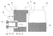
図1乃至図3は本発明のガスタービンの冷却構造の第1の実施の形態を示す図であり、図1は本発明のガスタービンの冷却構造の第1の実施の形態を適用したガスタービンの要部構成を示す縦断面図、図2は図1の符号Aで示す本発明のガスタービンの冷却構造の第1の実施の形態を拡大して示す断面図、図3は図1に示す本発明のガスタービンの冷却構造の第1の実施の形態を適用したガスタービンの要部構成をIII−III矢視から見た横断面図である。図1中、下半部を省略している。また、図1中、破線の矢印は圧縮空気及び冷却空気の流れを示している。
Embodiments of a cooling structure for a gas turbine according to the present invention will be described below with reference to the drawings.
[First Embodiment]
1 to 3 are views showing a first embodiment of a cooling structure for a gas turbine according to the present invention, and FIG. 1 is a gas turbine to which the first embodiment of a cooling structure for a gas turbine according to the present invention is applied. FIG. 2 is an enlarged cross-sectional view showing a first embodiment of the cooling structure for a gas turbine of the present invention indicated by reference numeral A in FIG. 1, and FIG. 3 is shown in FIG. It is the cross-sectional view which looked at the principal part structure of the gas turbine which applied 1st Embodiment of the cooling structure of the gas turbine of this invention from the III-III arrow. In FIG. 1, the lower half is omitted. Moreover, the broken-line arrow in FIG. 1 has shown the flow of compressed air and cooling air.
本実施の形態においては、圧縮機の出口スペースとタービン1段ホイールの上流側ホイールスペースとを区画する隔壁に設けたインピンジ冷却孔を介して、圧縮機出口の圧縮空気をタービン1段ホイール及びタービン1段動翼の翼植込み部に噴き付けてこれらを直接冷却するガスタービンの冷却構造を説明する。 In the present embodiment, the compressed air at the compressor outlet is supplied to the turbine first stage wheel and the turbine through the impingement cooling holes provided in the partition wall that partitions the outlet space of the compressor and the upstream wheel space of the turbine first stage wheel. A cooling structure for a gas turbine that directly sprays the blades of the first stage blades and cools them will be described.
図1において、ガスタービンは、空気を圧縮する圧縮機1と、圧縮機1で圧縮された空気と燃料とを燃焼させる燃焼器2と、燃焼器2で生成した燃焼ガスによって駆動されるタービン3とを備えている。
In FIG. 1, a gas turbine includes a compressor 1 that compresses air, a
このガスタービンでは、圧縮機1の圧縮機ロータ4と、タービン3のタービンロータ5と、圧縮機ロータ4及びタービンロータ5を同心円状に連結する中間軸6とで、一体となって回転するガスタービンロータが構成されている。ガスタービンロータは、ケーシング9によって覆われている。
In this gas turbine, the gas that rotates integrally with the compressor rotor 4 of the compressor 1, the turbine rotor 5 of the
圧縮機ロータ4は、詳細には図示していないが、外周部に圧縮機動翼7を複数備えた圧縮機ホイール8を軸方向に複数(図1では最終段のみ図示)積み重ねることで形成されている。圧縮機ホイール8とケーシング9との間には、圧縮機主流路40が形成されている。圧縮機主流路40内において、ケーシング9の内壁に固定された圧縮機静翼10が圧縮機動翼7と軸方向に交互に設置されている。
Although not shown in detail, the compressor rotor 4 is formed by stacking a plurality of
タービンロータ5は、外周部にタービン動翼11(図1ではタービン1段動翼11aのみ図示)を複数備えたタービンホイール12(図1ではタービン1段ホイール12aのみ図示)とスペーサ13とを軸方向に交互に少なくとも1段積み重ねることで形成され、接続する中間軸6と共にスタッキングボルト14により締結されている。タービン1段ホイール12aの回転中心には、中心孔18が設けられている。タービンホイール12の外周部には、翼溝(図示せず)が所定の間隔をもって複数形成されている。タービン動翼11は、タービンホイール12との連結部である翼植込み部(図示せず)を有している。すなわち、タービン動翼11は、翼植込み部をタービンホイール12の翼溝に嵌合させることでタービンホイール12に連結するように構成されている。タービンホイール12とケーシング9との間には、燃焼器2で生成された燃焼ガスが通過する流路41が形成されている。流路41内において、ケーシング9の内周側に固定したタービン静翼15がタービン動翼11と軸方向に交互に設置されている。
The turbine rotor 5 has a turbine wheel 12 (only the turbine
中間軸6には、軸方向に延びる中心孔19が設けられている。この中心孔19は、タービン1段ホイール12aの中心孔18に連通している。中間軸6は、インナーケーシング16によって間隙を介して外周を覆われている。インナーケーシング16は、圧縮機1の出口スペース42とタービン1段ホイール12aの上流側のホイールスペース43aとを区画する隔壁部16aを有しており、ストラット17等を介しケーシング9等に固定されている。中間軸6とインナーケーシング16との間には、冷却空気流路44が形成されている。中間軸6には、冷却空気流路44と中間軸6の中心孔19とを連通する流入孔20が設けられている。流入孔20は、中間軸6の径方向に延びており、中間軸6の周方向に所定間隔で複数設けられている。インナーケーシング16の内周側における流入孔20より下流側には、シール21が設置されている。シール21は、冷却空気流路44とタービン1段ホイール12aの上流側のホイールスペース43aとを隔て、冷却空気流路44を流れる圧縮空気がホイールスペース43a内に侵入するのを抑制するものである。
The
圧縮機主流路40を流れる圧縮空気101の一部は、圧縮機ロータ4とインナーケーシング16の間隙から、インナーケーシング16の内周側に流入する。この圧縮空気101は、冷却空気流路44を通り、中間軸6の流入孔20及び中心孔19やタービン1段ホイール12aの中心孔18を介してタービンロータ5の内部に流入し、シール空気や冷却空気102として使用される。このとき、冷却空気流路44を流通する圧縮空気101は、シール21によりタービン1段ホイール12aの上流側のホイールスペース43a内への流入が抑制される。
Part of the
インナーケーシング16の隔壁部16aには、圧縮機1の出口スペース42からホイールスペース43aに向かって、インピンジ冷却構造30が設けられている。
An
次に、本発明のガスタービンの冷却構造の第1の実施の形態の詳細な構造を図2及び図3を用いて説明する。図2中、破線の矢印は圧縮空気及び冷却空気の流れを示している。また、図3中、下半部を省略している。また、図3中では省略されているが、静翼15はケーシング9の内周側に同心円状に一定間隔で複数固定されている。なお、図2及び図3において、図1に示す符号と同符合のものは、同一部分であるので、その詳細な説明は省略する。
図2において、インピンジ冷却構造30では、インナーケーシング16の隔壁部16aにおける圧縮機1(図1参照)の出口スペース42側に、タービン1段ホイール12aのホイールスペース43a側に貫通しない段付穴31が形成されている。段付穴31は、出口スペース42側の大径穴部と、ホイールスペース43a側の小径穴部とで構成されている。
Next, the detailed structure of the first embodiment of the cooling structure for the gas turbine of the present invention will be described with reference to FIGS. In FIG. 2, broken arrows indicate the flow of compressed air and cooling air. Also, in FIG. 3, the lower half is omitted. Although omitted in FIG. 3, a plurality of
2, in the
段付穴31の底面となる隔壁部16aには、段付穴31とホイールスペース43aとを連通するインピンジ冷却孔32が複数設けられている。インピンジ冷却孔32は、その出口部の向きがタービン1段ホイール12aの表面及びタービン1段動翼11aの翼植込み部の表面の向きに対向するように設けられている。インピンジ冷却孔32は、圧縮機1の出口スペース42の圧縮空気101をタービン1段ホイール12aの表面及びタービン1段動翼11aの翼植込み部の表面に噴き付けるものである。
A plurality of impingement cooling holes 32 communicating the stepped
段付穴31の大径穴部側(隔壁部16aにおけるインピンジ冷却孔32の圧縮空気流入側)には、インピンジ冷却孔32に流入する圧縮空気(冷却空気)103の流量又は圧力を調整可能な調整部としてのオリフィスプレート33が着脱可能に設置されており、例えば、ボルトや螺子(図示せず)で固定されている。オリフィスプレート33は、オリフィス径の異なる複数種類のプレートが予め用意されている。オリフィスプレート33と段付穴31の小径穴部とで、複数のインピンジ冷却孔32に圧縮空気(冷却空気)103を分配する冷却空気ヘッダ34が形成される。
On the large diameter hole side of the stepped hole 31 (on the compressed air inflow side of the
インピンジ冷却構造30は、図3に示すように、インナーケーシング16の隔壁部16aに所定の間隔で同心円状に複数(図3では上半部で7個)設けられている。
As shown in FIG. 3, a plurality of
次に、本発明のガスタービンの冷却構造の第1の実施の形態の作用を図1乃至図3を用いて説明する。
本実施の形態において、図1に示す圧縮機主流路40を流れて圧縮機1の出口スペース42に流入した圧縮空気101の一部は、図2に示すように、オリフィスプレート33を通って圧力又は流量を調整され、冷却空気103として冷却空気ヘッダ34に供給される。冷却空気ヘッダ34に供給された冷却空気103は、複数のインピンジ冷却孔32からタービン1段ホイール12aのホイールスペース43aに噴出する。
Next, the operation of the first embodiment of the gas turbine cooling structure of the present invention will be described with reference to FIGS.
In the present embodiment, a part of the
インピンジ冷却孔32から噴出したインピンジ冷却空気104は、タービン1段ホイール12a及びタービン1段動翼11aの翼植込み部の外表面に衝突する。この衝突噴流により、タービン1段ホイール12a及びタービン1段動翼11aの翼植込み部が直接冷却される。このとき、ホイールスペース43aもインピンジ冷却空気104により冷却されてホイールスペース43aの温度も低下するため、ホイールスペース43aで対流する冷却空気によりタービン1段ホイール12a及びタービン1段動翼11aの翼植込み部は間接的にも冷却される。
The
タービン1段ホイール12a及びタービン1段動翼11aの翼植込み部を冷却した後の冷却空気は、タービン1段動翼11aの翼植込み部とインナーケーシング16の間隙から流路41に流入して、流路41を通過する燃焼ガスに合流する。
The cooling air after cooling the blade implanted portion of the turbine
本実施の形態においては、インピンジ冷却構造30のインピンジ冷却孔32の出口を、インナーケーシング16の隔壁部16aにおけるタービン1段ホイール12a及びタービン1段動翼11aに対向する面に設けて、インピンジ冷却空気104をタービン1段ホイール12a及びタービン1段動翼11aの翼植込み部に直接噴き付けることにより、これらを直接冷却している。このため、圧縮機から抽気した圧縮空気でタービン1段ホイールの上流側ホイールスペースを冷却して間接的にタービン1段ホイール及びタービン1段動翼の翼植込み部を冷却することでメタル温度を低下させる従来の冷却方法に比べて、熱伝達率が高く、メタル温度を効率的に低下させることができる。このため、冷却空気として抽気する圧縮空気の流量を低減させることができ、ガスタービンの効率及び出力が向上する。
In the present embodiment, the
また、本実施の形態においては、インピンジ冷却構造30を隔壁部16aの周方向に複数設置しているので、タービン1段ホイール12a及び1段動翼11aの翼植込み部を均一に冷却することができる。さらに、インピンジ冷却構造30を所定の間隔で同心円状に配置することにより、より均一で効率的な冷却が可能となる。
Further, in the present embodiment, since a plurality of
ところで、圧縮機から抽気した圧縮空気でタービン1段ホイールの上流側ホイールスペースを冷却して間接的にタービン1段ホイール及びタービン1段動翼の翼植込み部を冷却する従来の冷却方法においては、ホイールスペースの径方向及び周方向位置により温度偏差が生じやすく、高温の箇所を基準に冷却空気の流量を調整する必要があった。 By the way, in the conventional cooling method of cooling the blade implantation portion of the turbine first stage wheel and the turbine first stage rotor blade indirectly by cooling the upstream wheel space of the turbine first stage wheel with the compressed air extracted from the compressor, Temperature deviations are likely to occur depending on the radial and circumferential positions of the wheel space, and it was necessary to adjust the flow rate of the cooling air based on the high-temperature portion.
それに対して、本実施の形態においては、各インピンジ冷却構造30のオリフィスプレート33として、オリフィス径の異なる複数種類のオリフィスプレートを予め用意している。このため、ガスタービンの使用条件などにより、冷却空気の流量や圧力に過不足が生じた場合や、タービン1段ホイール12a及びタービン1段動翼11aの翼植込み部の周方向に温度偏差が生じた場合には、ガスタービンの据付後であっても、燃焼器2を取り外して、各インピンジ冷却構造30のオリフィスプレート33をそれぞれ適切なオリフィス径を持つオリフィスプレートに変更することができる。このことにより、冷却空気ヘッダ34内に流入する冷却空気103の流量や圧力をインピンジ冷却構造30ごとに独立にかつ容易に調整することができるため、タービン1段ホイール12a及び1段動翼11aの翼植込み部を一層均一に冷却することができる。この結果、高温の箇所を基準に冷却空気の流量を調整する必要がなくなり、冷却空気として抽気する圧縮空気の流量を一層低減させることができ、ガスタービンの効率及び出力が一層向上する。
On the other hand, in this embodiment, a plurality of types of orifice plates having different orifice diameters are prepared in advance as the
さらに、ガスタービンの性能向上ため、燃焼温度や翼等の材質を変更する場合においても、インナーケーシング16や中間軸6を分解、再加工及び再組立することなしに、オリフィスプレート33を適切なオリフィス径を持つオリフィスプレートに交換することで、インピンジ冷却空気104の流量や圧力を容易に調整することができ、分解組立にかかる労力や時間及びコストを削減することができる。
Furthermore, in order to improve the performance of the gas turbine, even when the material such as the combustion temperature and the blades are changed, the
また、インナーケーシング16における流入孔18より下流側にシール21を設置しているので、冷却空気流路44を流通する圧縮空気(冷却空気)102がタービン1段ホイール12aのホイールスペース43aに流入することを抑制できる。したがって、インピンジ冷却孔32から噴出するインピンジ冷却空気104の流れが冷却空気流路44からホイールスペース43aに流入する冷却空気により乱されることがないので、タービン1段ホイール12a及びタービン1段動翼11aの翼植込み部の部分に確実にインピンジ冷却空気104を噴き付けることができる。
Further, since the
上述したように、本発明のガスタービン冷却構造の第1の実施の形態によれば、圧縮機1からの圧縮空気をインピンジ冷却孔32を介して直接タービン1段ホイール12a及びタービン1段動翼11aの翼植込み部に噴き付けてこれらを冷却するので、タービンホイール12a及びタービン1段動翼11aの翼植込み部を効率的に冷却することができる。
As described above, according to the first embodiment of the gas turbine cooling structure of the present invention, the compressed air from the compressor 1 is directly supplied to the turbine
[第2の実施の形態]
次に、本発明のガスタービン冷却構造の第2の実施の形態を図4及び図5を用いて説明する。
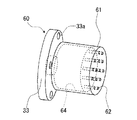
図4及び図5は本発明のガスタービン冷却構造の第2の実施の形態を示す図であり、図4は本発明のガスタービンの冷却構造の第2の実施の形態を示す断面図、図5は図4に示す本発明のガスタービンの冷却構造の第2の実施の形態を構成するカートリッジを示す斜視図である。図4中、カートリッジ60をインナーケーシング16から取り外した状態で示している。また、矢印はカートリッジ60のインナーケーシング16に対する取付方向を示している。なお、図4及び図5において、図1乃至図3に示す符号と同符合のものは、同一部分であるので、その詳細な説明は省略する。
[Second Embodiment]
Next, a second embodiment of the gas turbine cooling structure of the present invention will be described with reference to FIGS.
4 and 5 are views showing a second embodiment of the gas turbine cooling structure of the present invention, and FIG. 4 is a cross-sectional view showing the second embodiment of the gas turbine cooling structure of the present invention. FIG. 5 is a perspective view showing a cartridge constituting the second embodiment of the cooling structure of the gas turbine of the present invention shown in FIG. In FIG. 4, the
本発明のガスタービン冷却構造の第2の実施の形態は、第1の実施の形態がインピンジ冷却孔32をインターケーシング16の隔壁部16aに形成するものであるのに対して、インピンジ冷却孔62を有するカートリッジ60を隔壁部16aに着脱可能に取り付けるものである。
In the second embodiment of the gas turbine cooling structure of the present invention, the
具体的には、図4に示すインピンジ冷却構造50では、インナーケーシング16の隔壁部16aに、圧縮機1(図1参照)の出口スペース42とタービン1段ホイール12aのホイールスペース43aとを連通する段付きの取付孔51が形成されている。取付孔51は、出口スペース42側の大径穴部と、ホイールスペース43a側の小径穴部とで構成されている。取付孔51のホイールスペース43a側の開口は、隔壁部16aにおけるタービン1段ホイール12a及びタービン1段動翼11aの翼植込み部に対向する部分に設けられている。取付孔51は、図3に示す第1の実施の形態と同様に、隔壁部16aに所定の間隔で同心円状に複数設けられている。
Specifically, in the
インナーケーシング16の各取付孔51には、出口スペース42の圧縮空気をタービン1段ホイール12a及びタービン1段動翼11aの翼植込み部に直接噴き付けるためのカートリッジ60がそれぞれ取り付けられている。図4及び図5に示すように、カートリッジ60は、一方側に出口スペース42の圧縮空気が流入する開口部61aを有する共に他方側の底部にインピンジ冷却孔62を有する有底筒状の本体部61と、本体部61の開口部61aに取り付けたオリフィスプレート33とで構成されている。オリフィスプレート33は、カートリッジ60のインピンジ冷却孔62に流入する圧縮空気(冷却空気)の流量又は圧力を調整可能な調整部として機能する。本体部61とオリフィスプレート33とで冷却空気ヘッダ64が形成されている。各カートリッジ60は、取付孔51に対してそれぞれ独立して着脱可能である。また、各カートリッジ60に対しては、オリフィスプレート33のオリフィス径及びインピンジ冷却孔62の孔径や孔位置、員数が異なる複数種類のカートリッジが予め用意されている。カートリッジ60は、オリフィスプレート33が出口スペース42側に、インピンジ冷却孔62が形成された本体部61の底部がホイールスペース43a側になるように固定されている。カートリッジ60の固定方法として、例えば、オリフィスプレート33にボルト用下穴33aを、取付孔51の大径部側の底面にねじ穴51aを設けて、ボルトや螺子などの締結具(図示せず)で固定する方法が用いられる。
Each of the mounting
本発明のガスタービン冷却構造の第2の実施の形態によれば、インピンジ冷却孔62を有するカートリッジ60を、インナーケーシング16の隔壁部16aにおけるタービン1段ホイール12a及びタービン1段動翼11aの翼植込み部に対向する部分に設けた取付孔51に取り付けるので、第1の実施の形態と同様の効果を得ることができる。
According to the second embodiment of the gas turbine cooling structure of the present invention, the
また、本実施の形態によれば、インピンジ冷却孔62を、インナーケーシング16の隔壁部16aでなく、カートリッジ60の本体部61の底部に形成するので、インナーケーシング16の加工に必要な時間や労力、コストを削減することができる。
Further, according to the present embodiment, the
さらに、本実施の形態によれば、各カートリッジ60をインーケーシング16の各取付孔51に対して独立して着脱可能としたので、ガスタービンの運転条件、タービン1段ホイール12aやタービン1段動翼11aの翼植込みのメタル温度、又はタービン1段ホイール12aのホイールスペース43aの雰囲気温度に応じて、既設のカートリッジ60を、オリフィスプレート33のオリフィス径又はインピンジ冷却孔62の位置や員数、冷却孔径の異なるカートリッジに変更することができる。すなわち、ガスタービンの諸条件や諸状態に応じて、既設の各カートリッジ60に対して適切なカートリッジに個別に交換することができる。このため、インピンジ冷却空気104の流量や圧力を第1の実施の形態よりも詳細に調整することができると共にインピンジ冷却を行う冷却範囲も調整することができる。したがって、タービン1段ホイール12a及びタービン1段動翼11aの翼植込みをより一層均一に冷却することができる。この結果、冷却空気として抽気する圧縮空気の流量をより一層低減させることができ、ガスタービンの効率及び出力がより一層向上する。
Further, according to the present embodiment, each
また、本実施の形態によれば、インピンジ冷却空気104の流量や圧力を調整する場合、燃焼器2を取り外し、既設の各カートリッジ60に対して適切なカートリッジに個別に交換すればよいので、容易にインピンジ冷却空気104の流量や圧力を調整することができる。特に、インピンジ冷却孔62の位置や員数、冷却孔径を変更することでインピンジ冷却空気104の流量や圧力、冷却範囲を調整しようとする場合、カートリッジ60を交換するだけなので、インナーケーシング16に対してインピンジ冷却孔32の再加工等を行う必要が生じる第1の実施の形態の場合よりも容易に調整することができる。
Further, according to the present embodiment, when adjusting the flow rate or pressure of the
[その他の実施の形態]
なお、上述した実施の形態においては、インピンジ冷却孔を備える冷却構造をインナーケーシング16に設けた例を示したが、本発明の本質的な効果は、圧縮機1の出口スペース42とタービン1段ホイール12aの上流側のホイールスペース43aとを区画する隔壁にインピンジ冷却孔を設けることにより、タービン1段ホイール12a及びタービン1段動翼11aの翼植込み部に冷却空気を直接噴き付けて、効率的に冷却することであり、必ずしも、この冷却構造をインナーケーシング16に設ける必要はない。例えば、第1段静翼サポートリングが出口スペース42とホイールスペース43aとを区画する場合には、このサポートリングにこの冷却構造を適用することができる。
[Other embodiments]
In the above-described embodiment, an example in which the cooling structure including the impingement cooling holes is provided in the
また、上述した実施の形態においては、インピンジ冷却孔32、62に流入する圧縮空気(冷却空気)103の流量又は圧力を調整可能な調整部として、オリフィスプレート33を例に示したが、本発明の本質的な効果は、タービン1段ホイール12a及びタービン1段動翼の翼植込み部に噴き付ける冷却空気の流量又は圧力を調整することであり、上記の本質的な効果を得る限りにおいては、必ずしもオリフィスプレート33に限定されるものではない。
Further, in the above-described embodiment, the
なお、上述した実施の形態においては、インピンジ冷却孔を備える冷却構造を隔壁部16aに同心円状に複数設けた例を示したが、本発明の本質的な効果は、出口スペース42とホイールスペース43aを区画する隔壁にインピンジ冷却孔を複数備えることにより、タービン1段ホイール12a及びタービン1段動翼の翼植込み部を均一に冷却することであり、上記の本質的効果を得る限りにおいては、必ずしも冷却構造を上記配置に限定するものではない。
In the above-described embodiment, an example in which a plurality of cooling structures provided with impingement cooling holes are provided concentrically on the
また、上述した実施の形態においては、オリフィスプレート33を備える冷却構造の例を示したが、本発明の本質的な効果は、インピンジ冷却孔を備えることにより、タービン1段ホイール12a及びタービン1段動翼11aの翼植込み部に冷却空気を直接噴き付けて効率的に冷却することであり、必ずしも、オリフィスプレート33を必要としない。例えば、インピンジ冷却孔62の位置や員数、冷却孔径を適切に選択することで、タービン1段ホイール12a及びタービン1段動翼11aの翼植込み部に噴き付ける冷却空気の流量や圧力、冷却範囲を適切に調整して効率的に冷却することも可能である。
In the above-described embodiment, the example of the cooling structure including the
なお、上述した第1の実施の形態においては、オリフィスプレート33をインナーケーシング16の段付穴31の大径穴部側にボルトや螺子の締結具で固定する例を示したが、オリフィスプレート33及び段付穴31の大径穴部側の側面にねじを形成し、オリフィスプレート33を段付穴31の大径穴部側の側面に螺着させて固定することもできる。
In the first embodiment described above, the
また、上述した第2の実施の形態においては、カートリッジ60をインナーケーシング16の取付孔51にボルトや螺子などの締結具で固定する例を示したが、カートリッジ60の外側面及び取付孔51の側面にねじを形成し、カートリッジ60を取付孔51の側面に螺着させて固定することもできる。
In the second embodiment described above, the
なお、上述した第2の実施の形態においては、カートリッジ60を、有底筒状の本体部61と、本体部61に取り付けたオリフィスプレート33とで構成した例を示したが、カートリッジを、オリフィスプレート33とは別体で、本体部61のみで構成することもできる。この場合、取付孔51の圧縮空気流入側にオリフィスプレート33を取り付け、オリフィスプレート33より下流側の取付孔51にカートリッジ60をオリフィスプレート33とは別個に取り付ける。この場合も、上述した第2の実施の形態と同様な効果を得ることができる。また、ガスタービンの諸条件や諸状態に応じて、オリフィスプレート33とカートリッジを別個に変更することができるので、インピンジ冷却空気104の流量や圧力を一層微調整することができる。
In the second embodiment described above, an example in which the
また、本発明は上述した実施の形態に限られるものではなく、様々な変形例が含まれる。上記した実施形態は本発明をわかり易く説明するために詳細に説明したものであり、必ずしも説明した全ての構成を備えるものに限定されるものではない。例えば、ある実施形態の構成の一部を他の実施の形態の構成に置き換えることが可能であり、また、ある実施形態の構成に他の実施の形態の構成を加えることも可能である。また、各実施形態の構成の一部について、他の構成の追加、削除、置換をすることも可能である。 Further, the present invention is not limited to the above-described embodiment, and includes various modifications. The above-described embodiment has been described in detail for easy understanding of the present invention, and is not necessarily limited to the one having all the configurations described. For example, part of the configuration of one embodiment can be replaced with the configuration of another embodiment, and the configuration of another embodiment can be added to the configuration of one embodiment. Moreover, it is also possible to add, delete, or replace another configuration for a part of the configuration of each embodiment.
1 圧縮機
2 燃焼器
3 タービン
11a タービン1段動翼(タービン動翼)
12a タービン1段ホイール(タービンホイール)
16a 隔壁部(隔壁)
32、62 インピンジ冷却孔
33 オリフィスプレート(調整部)
51 取付孔
60 カートリッジ
61 本体部
61a 開口部
42 出口スペース
43a ホイールスペース
DESCRIPTION OF SYMBOLS 1
12a Turbine one-stage wheel (turbine wheel)
16a Partition (partition)
32, 62
51 Mounting
Claims (2)
前記圧縮機の出口スペースと前記タービンホイールの上流側のホイールスペースとを区画する隔壁に設けられ、前記圧縮機の出口スペースの圧縮空気を前記タービンホイール及び前記タービン動翼の前記タービンホイールとの連結部外表面に衝突させる一群のインピンジ冷却孔と、
前記一群のインピンジ冷却孔の圧縮空気流入側に着脱可能に設置され、前記一群のインピンジ冷却孔に流入する圧縮空気の流量又は圧力を調整可能な調整部と、
前記調整部を介した圧縮空気を前記一群のインピンジ冷却孔へ分配するヘッダとを備える
ことを特徴とするガスタービンの冷却構造。 Combustion gas generated by the combustor having at least one stage of a compressor wheel that compresses air, a combustor that combusts the air and fuel compressed by the compressor, and a turbine blade having an outer peripheral portion. A gas turbine cooling structure comprising a turbine driven by
The compressor is provided in a partition partitioning an outlet space of the compressor and a wheel space upstream of the turbine wheel, and the compressed air in the outlet space of the compressor is connected to the turbine wheel and the turbine wheel of the turbine blade. a group of impingement cooling holes to impinge on the part outer surface,
An adjuster that is detachably installed on the compressed air inflow side of the group of impingement cooling holes and is capable of adjusting the flow rate or pressure of the compressed air flowing into the group of impingement cooling holes;
A cooling structure for a gas turbine, comprising: a header that distributes compressed air via the adjusting unit to the group of impingement cooling holes .
前記一群のインピンジ冷却孔は、前記隔壁の周方向に複数設けられた
ことを特徴とするガスタービンの冷却構造。 The gas turbine cooling structure according to claim 1,
A cooling structure for a gas turbine, wherein the group of impingement cooling holes is provided in the circumferential direction of the partition wall.
Priority Applications (4)
| Application Number | Priority Date | Filing Date | Title |
|---|---|---|---|
| JP2013238983A JP6245739B2 (en) | 2013-11-19 | 2013-11-19 | Gas turbine cooling structure |
| CN201410647462.2A CN104653295B (en) | 2013-11-19 | 2014-11-14 | Cooling System for Gas Turbine |
| US14/546,138 US10072576B2 (en) | 2013-11-19 | 2014-11-18 | Cooling system for gas turbine |
| EP14193906.6A EP2873805B1 (en) | 2013-11-19 | 2014-11-19 | Cooling system for gas turbine |
Applications Claiming Priority (1)
| Application Number | Priority Date | Filing Date | Title |
|---|---|---|---|
| JP2013238983A JP6245739B2 (en) | 2013-11-19 | 2013-11-19 | Gas turbine cooling structure |
Publications (3)
| Publication Number | Publication Date |
|---|---|
| JP2015098826A JP2015098826A (en) | 2015-05-28 |
| JP2015098826A5 JP2015098826A5 (en) | 2016-12-15 |
| JP6245739B2 true JP6245739B2 (en) | 2017-12-13 |
Family
ID=52020937
Family Applications (1)
| Application Number | Title | Priority Date | Filing Date |
|---|---|---|---|
| JP2013238983A Active JP6245739B2 (en) | 2013-11-19 | 2013-11-19 | Gas turbine cooling structure |
Country Status (4)
| Country | Link |
|---|---|
| US (1) | US10072576B2 (en) |
| EP (1) | EP2873805B1 (en) |
| JP (1) | JP6245739B2 (en) |
| CN (1) | CN104653295B (en) |
Families Citing this family (1)
| Publication number | Priority date | Publication date | Assignee | Title |
|---|---|---|---|---|
| CN112710870B (en) * | 2020-12-21 | 2022-07-08 | 成都成发泰达航空科技有限公司 | Performance detection device for APU (auxiliary Power Unit) speed sensor |
Family Cites Families (16)
| Publication number | Priority date | Publication date | Assignee | Title |
|---|---|---|---|---|
| US4242045A (en) * | 1979-06-01 | 1980-12-30 | General Electric Company | Trap seal for open circuit liquid cooled turbines |
| US4456427A (en) * | 1981-06-11 | 1984-06-26 | General Electric Company | Cooling air injector for turbine blades |
| DE3603350A1 (en) | 1986-02-04 | 1987-08-06 | Walter Prof Dipl Ph Sibbertsen | METHOD FOR COOLING THERMALLY LOADED COMPONENTS OF FLOWING MACHINES, DEVICE FOR CARRYING OUT THE METHOD AND TRAINING THERMALLY LOADED BLADES |
| US5413463A (en) * | 1991-12-30 | 1995-05-09 | General Electric Company | Turbulated cooling passages in gas turbine buckets |
| JP3337393B2 (en) * | 1997-04-23 | 2002-10-21 | 三菱重工業株式会社 | Gas turbine cooling blade |
| US6234746B1 (en) * | 1999-08-04 | 2001-05-22 | General Electric Co. | Apparatus and methods for cooling rotary components in a turbine |
| JP3889727B2 (en) | 2003-07-01 | 2007-03-07 | 株式会社日立製作所 | Gas turbine and cooling air introduction method |
| JP4319087B2 (en) * | 2004-05-06 | 2009-08-26 | 株式会社日立製作所 | gas turbine |
| GB0513468D0 (en) * | 2005-07-01 | 2005-08-10 | Rolls Royce Plc | A mounting arrangement for turbine blades |
| JP2007146787A (en) * | 2005-11-29 | 2007-06-14 | Mitsubishi Heavy Ind Ltd | Gas turbine |
| GB2457427A (en) * | 2007-12-14 | 2009-08-19 | Rolls Royce Plc | Gas turbine engine cooling flow modulation arrangement comprising fluidic valves |
| US20090226327A1 (en) * | 2008-03-07 | 2009-09-10 | Siemens Power Generation, Inc. | Gas Turbine Engine Including Temperature Control Device and Method Using Memory Metal |
| JP5495893B2 (en) * | 2010-03-30 | 2014-05-21 | 三菱重工業株式会社 | Gas turbine and method for modifying the same |
| US8677766B2 (en) * | 2010-04-12 | 2014-03-25 | Siemens Energy, Inc. | Radial pre-swirl assembly and cooling fluid metering structure for a gas turbine engine |
| JP4841678B2 (en) * | 2010-04-15 | 2011-12-21 | 川崎重工業株式会社 | Turbine vane of gas turbine |
| US8529195B2 (en) | 2010-10-12 | 2013-09-10 | General Electric Company | Inducer for gas turbine system |
-
2013
- 2013-11-19 JP JP2013238983A patent/JP6245739B2/en active Active
-
2014
- 2014-11-14 CN CN201410647462.2A patent/CN104653295B/en active Active
- 2014-11-18 US US14/546,138 patent/US10072576B2/en active Active
- 2014-11-19 EP EP14193906.6A patent/EP2873805B1/en active Active
Also Published As
| Publication number | Publication date |
|---|---|
| CN104653295A (en) | 2015-05-27 |
| JP2015098826A (en) | 2015-05-28 |
| EP2873805A1 (en) | 2015-05-20 |
| US10072576B2 (en) | 2018-09-11 |
| CN104653295B (en) | 2017-04-26 |
| EP2873805B1 (en) | 2016-07-20 |
| US20150135715A1 (en) | 2015-05-21 |
Similar Documents
| Publication | Publication Date | Title |
|---|---|---|
| US9341074B2 (en) | Active clearance control manifold system | |
| US8727704B2 (en) | Ring segment with serpentine cooling passages | |
| US7287955B2 (en) | Gas turbine clearance control devices | |
| JP4185476B2 (en) | Device for controlling clearance in a gas turbine | |
| EP2206886B1 (en) | Transition piece for a gas turbine engine, corresponding gas turbine engine and manufacturing method | |
| JP6055174B2 (en) | Inducer for gas turbine system | |
| JP6324548B2 (en) | Gas turbine engine with a rotor centering cooling system in the exhaust diffuser | |
| US9366436B2 (en) | Combustion chamber of a gas turbine | |
| US20130084162A1 (en) | Gas Turbine | |
| US6659716B1 (en) | Gas turbine having thermally insulating rings | |
| US7140836B2 (en) | Casing arrangement | |
| EP2243931A2 (en) | Turbine casing cooling | |
| RU2537113C1 (en) | Gas turbine with thermal protection and control method | |
| JP2009008086A (en) | Device for cooling slot of turbomachine rotor disk | |
| US9335048B2 (en) | Combustion chamber of a gas turbine | |
| US20130011238A1 (en) | Cooled ring segment | |
| JP6411754B2 (en) | Flow sleeve and associated method for thermal control of a double wall turbine shell | |
| EP2378088A2 (en) | Turbine with a double casing | |
| JP6245739B2 (en) | Gas turbine cooling structure | |
| JP4100903B2 (en) | Bolt joint for rotor disk and method for reducing thermal gradient therein | |
| WO2017110104A1 (en) | Gas turbine | |
| RU2352788C1 (en) | High-temperature gas turbine | |
| JP2021535313A (en) | Modular casing manifold for cooling fluid of gas turbine engine | |
| CN113994073A (en) | Sealing ring for a wheel of a turbine wheel | |
| JP2019060336A (en) | Turbine exhaust diffuser |
Legal Events
| Date | Code | Title | Description |
|---|---|---|---|
| A521 | Request for written amendment filed |
Free format text: JAPANESE INTERMEDIATE CODE: A523 Effective date: 20161024 |
|
| A621 | Written request for application examination |
Free format text: JAPANESE INTERMEDIATE CODE: A621 Effective date: 20161024 |
|
| A977 | Report on retrieval |
Free format text: JAPANESE INTERMEDIATE CODE: A971007 Effective date: 20170720 |
|
| A131 | Notification of reasons for refusal |
Free format text: JAPANESE INTERMEDIATE CODE: A131 Effective date: 20170725 |
|
| A521 | Request for written amendment filed |
Free format text: JAPANESE INTERMEDIATE CODE: A523 Effective date: 20170921 |
|
| TRDD | Decision of grant or rejection written | ||
| A01 | Written decision to grant a patent or to grant a registration (utility model) |
Free format text: JAPANESE INTERMEDIATE CODE: A01 Effective date: 20171107 |
|
| A61 | First payment of annual fees (during grant procedure) |
Free format text: JAPANESE INTERMEDIATE CODE: A61 Effective date: 20171113 |
|
| R150 | Certificate of patent or registration of utility model |
Ref document number: 6245739 Country of ref document: JP Free format text: JAPANESE INTERMEDIATE CODE: R150 |
|
| S533 | Written request for registration of change of name |
Free format text: JAPANESE INTERMEDIATE CODE: R313533 |
|
| R350 | Written notification of registration of transfer |
Free format text: JAPANESE INTERMEDIATE CODE: R350 |