JP6239612B2 - Generalized residual prediction for scalable video coding and 3D video coding - Google Patents
Generalized residual prediction for scalable video coding and 3D video coding Download PDFInfo
- Publication number
- JP6239612B2 JP6239612B2 JP2015521666A JP2015521666A JP6239612B2 JP 6239612 B2 JP6239612 B2 JP 6239612B2 JP 2015521666 A JP2015521666 A JP 2015521666A JP 2015521666 A JP2015521666 A JP 2015521666A JP 6239612 B2 JP6239612 B2 JP 6239612B2
- Authority
- JP
- Japan
- Prior art keywords
- prediction
- video
- weighting
- coding
- layer
- Prior art date
- Legal status (The legal status is an assumption and is not a legal conclusion. Google has not performed a legal analysis and makes no representation as to the accuracy of the status listed.)
- Active
Links
- 238000000034 method Methods 0.000 claims description 189
- 230000002123 temporal effect Effects 0.000 claims description 53
- 241000023320 Luma <angiosperm> Species 0.000 claims description 45
- OSWPMRLSEDHDFF-UHFFFAOYSA-N methyl salicylate Chemical compound COC(=O)C1=CC=CC=C1O OSWPMRLSEDHDFF-UHFFFAOYSA-N 0.000 claims description 45
- 238000013139 quantization Methods 0.000 claims description 30
- 238000003860 storage Methods 0.000 claims description 27
- 238000004891 communication Methods 0.000 claims description 18
- 238000005070 sampling Methods 0.000 claims description 14
- 239000010410 layer Substances 0.000 description 275
- 230000033001 locomotion Effects 0.000 description 167
- 230000008569 process Effects 0.000 description 42
- 239000013598 vector Substances 0.000 description 37
- 239000011229 interlayer Substances 0.000 description 26
- 230000000875 corresponding effect Effects 0.000 description 25
- 230000005540 biological transmission Effects 0.000 description 14
- 238000012545 processing Methods 0.000 description 11
- 208000037170 Delayed Emergence from Anesthesia Diseases 0.000 description 9
- 230000011664 signaling Effects 0.000 description 9
- 230000003044 adaptive effect Effects 0.000 description 8
- 238000009499 grossing Methods 0.000 description 7
- 238000013500 data storage Methods 0.000 description 6
- 238000010586 diagram Methods 0.000 description 6
- 230000006870 function Effects 0.000 description 6
- 238000001914 filtration Methods 0.000 description 5
- 230000008901 benefit Effects 0.000 description 4
- 230000006835 compression Effects 0.000 description 4
- 238000007906 compression Methods 0.000 description 4
- 238000013507 mapping Methods 0.000 description 4
- 238000004458 analytical method Methods 0.000 description 3
- 238000005516 engineering process Methods 0.000 description 3
- 230000000007 visual effect Effects 0.000 description 3
- 238000006243 chemical reaction Methods 0.000 description 2
- 238000004590 computer program Methods 0.000 description 2
- 238000010276 construction Methods 0.000 description 2
- 239000000835 fiber Substances 0.000 description 2
- 239000011159 matrix material Substances 0.000 description 2
- 230000003287 optical effect Effects 0.000 description 2
- 238000005457 optimization Methods 0.000 description 2
- 230000010363 phase shift Effects 0.000 description 2
- 238000000638 solvent extraction Methods 0.000 description 2
- 238000012360 testing method Methods 0.000 description 2
- 230000007704 transition Effects 0.000 description 2
- 238000003491 array Methods 0.000 description 1
- 230000001413 cellular effect Effects 0.000 description 1
- 230000002596 correlated effect Effects 0.000 description 1
- 230000001419 dependent effect Effects 0.000 description 1
- 238000009795 derivation Methods 0.000 description 1
- 238000006073 displacement reaction Methods 0.000 description 1
- 238000011156 evaluation Methods 0.000 description 1
- 238000012432 intermediate storage Methods 0.000 description 1
- 230000001788 irregular Effects 0.000 description 1
- 239000004973 liquid crystal related substance Substances 0.000 description 1
- 238000004519 manufacturing process Methods 0.000 description 1
- 238000001228 spectrum Methods 0.000 description 1
- 238000012546 transfer Methods 0.000 description 1
- 230000009466 transformation Effects 0.000 description 1
Images


Classifications
-
- H—ELECTRICITY
- H04—ELECTRIC COMMUNICATION TECHNIQUE
- H04N—PICTORIAL COMMUNICATION, e.g. TELEVISION
- H04N13/00—Stereoscopic video systems; Multi-view video systems; Details thereof
- H04N13/10—Processing, recording or transmission of stereoscopic or multi-view image signals
- H04N13/106—Processing image signals
- H04N13/161—Encoding, multiplexing or demultiplexing different image signal components
-
- H—ELECTRICITY
- H04—ELECTRIC COMMUNICATION TECHNIQUE
- H04N—PICTORIAL COMMUNICATION, e.g. TELEVISION
- H04N19/00—Methods or arrangements for coding, decoding, compressing or decompressing digital video signals
- H04N19/50—Methods or arrangements for coding, decoding, compressing or decompressing digital video signals using predictive coding
- H04N19/597—Methods or arrangements for coding, decoding, compressing or decompressing digital video signals using predictive coding specially adapted for multi-view video sequence encoding
-
- H—ELECTRICITY
- H04—ELECTRIC COMMUNICATION TECHNIQUE
- H04N—PICTORIAL COMMUNICATION, e.g. TELEVISION
- H04N19/00—Methods or arrangements for coding, decoding, compressing or decompressing digital video signals
- H04N19/10—Methods or arrangements for coding, decoding, compressing or decompressing digital video signals using adaptive coding
- H04N19/102—Methods or arrangements for coding, decoding, compressing or decompressing digital video signals using adaptive coding characterised by the element, parameter or selection affected or controlled by the adaptive coding
- H04N19/103—Selection of coding mode or of prediction mode
- H04N19/105—Selection of the reference unit for prediction within a chosen coding or prediction mode, e.g. adaptive choice of position and number of pixels used for prediction
-
- H—ELECTRICITY
- H04—ELECTRIC COMMUNICATION TECHNIQUE
- H04N—PICTORIAL COMMUNICATION, e.g. TELEVISION
- H04N19/00—Methods or arrangements for coding, decoding, compressing or decompressing digital video signals
- H04N19/10—Methods or arrangements for coding, decoding, compressing or decompressing digital video signals using adaptive coding
- H04N19/169—Methods or arrangements for coding, decoding, compressing or decompressing digital video signals using adaptive coding characterised by the coding unit, i.e. the structural portion or semantic portion of the video signal being the object or the subject of the adaptive coding
- H04N19/187—Methods or arrangements for coding, decoding, compressing or decompressing digital video signals using adaptive coding characterised by the coding unit, i.e. the structural portion or semantic portion of the video signal being the object or the subject of the adaptive coding the unit being a scalable video layer
-
- H—ELECTRICITY
- H04—ELECTRIC COMMUNICATION TECHNIQUE
- H04N—PICTORIAL COMMUNICATION, e.g. TELEVISION
- H04N19/00—Methods or arrangements for coding, decoding, compressing or decompressing digital video signals
- H04N19/30—Methods or arrangements for coding, decoding, compressing or decompressing digital video signals using hierarchical techniques, e.g. scalability
- H04N19/33—Methods or arrangements for coding, decoding, compressing or decompressing digital video signals using hierarchical techniques, e.g. scalability in the spatial domain
Description
[0001]本開示は、映像コーディングに関するものである。 [0001] The present disclosure relates to video coding.
[0002]デジタル映像能力を広範なデバイス内に組み入れることができ、デジタルテレビと、デジタル直接放送システムと、無線放送システムと、パーソナルデジタルアシスタント(PDA)と、ラップトップ又はデスクトップコンピュータと、ダフレットコンピュータと、電子書籍リーダーと、デジタルカメラと、デジタル記録デバイスと、デジタルメディアプレーヤーと、ビデオゲームプレイ装置と、ビデオゲームコンソールと、セルラー又は衛星無線電話、いわゆる“スマートフォン”と、ビデオ会議装置と、ビデオストリーミングデバイスと、等、を含む。デジタル映像デバイスは、映像コーディング技法、例えば、MPEG−2、MPEG−4、ITU−T H.263、ITU−T H.264/MPEG−4、Part10、アドバンストビデオコーディング(Advanced Video Coding(AVC))、現在策定中の高効率映像コーディング(High Efficiency Video Coding(HEVC)規格、及び該規格の拡張版、によって定義される規格において説明されるそれら、を実装する。映像デバイスは、該映像コーディング技法を実装することによってより効率的にデジタル映像情報を送信、受信、符号化、復号、及び/又は格納することができる。
[0002] Digital video capabilities can be incorporated into a wide range of devices, including digital television, digital direct broadcast systems, wireless broadcast systems, personal digital assistants (PDAs), laptop or desktop computers, and doublet computers An electronic book reader, a digital camera, a digital recording device, a digital media player, a video game play device, a video game console, a cellular or satellite radio telephone, a so-called “smart phone”, a video conferencing device, and a video Including streaming devices, and so on. Digital video devices are based on video coding techniques such as MPEG-2, MPEG-4, ITU-TH. 263, ITU-TH. Standards defined by H.264 / MPEG-4,
[0003]映像コーディング技法は、映像シーケンスに固有の冗長性を低減又は除去するための空間的(イントラピクチャ)予測及び/又は時間的(インターピクチャ)予測を行う。ブロックに基づく映像コーディングでは、映像スライス(例えば、映像フレーム又は映像フレームの一部分)を映像ブロックに分割することができ、それらは、ツリーブロック、コーディングユニット(CU)及び/又はコーディングノードと呼ぶこともできる。ピクチャのイントラコーディングされた(I)スライス内の映像ブロックは、同じピクチャ内の近隣ブロック内の基準サンプルに関して空間的予測を用いて符号化される。ピクチャのインターコーディングされた(P又はB)スライス内の映像ブロックは、同じピクチャ内の近隣ブロック内の基準サンプルに関する空間的予測又はその他の基準ピクチャ内の基準サンプルに関する時間的予測を使用することができる。ピクチャは、フレームと呼ぶことができ、基準ピクチャは、基準フレームと呼ぶことができる。 [0003] Video coding techniques perform spatial (intra-picture) prediction and / or temporal (inter-picture) prediction to reduce or remove redundancy inherent in video sequences. In block-based video coding, a video slice (eg, a video frame or a portion of a video frame) can be divided into video blocks, which are also referred to as tree blocks, coding units (CUs) and / or coding nodes. it can. A video block in an intra-coded (I) slice of a picture is encoded using spatial prediction with respect to reference samples in neighboring blocks in the same picture. A video block in an intercoded (P or B) slice of a picture may use spatial prediction for reference samples in neighboring blocks in the same picture or temporal prediction for reference samples in other reference pictures. it can. A picture can be referred to as a frame, and a reference picture can be referred to as a reference frame.
[0004]空間的予測又は時間的予測の結果、コーディングされるべきブロックに関する予測ブロックが得られる。残差データは、コーディングされるべきオリジナルのブロックと予測ブロックとの間のピクセル差分を表す。インターコーディングされたブロックは、予測ブロックを形成する基準サンプルのブロックを指し示す動きベクトル、及びコーディングされたブロックと予測ブロックとの間の差分を示す残差データにより符号化される。イントラコーディングされたブロックは、イントラコーディングモード及び残差データにより符号化される。さらなる圧縮のために、残差データは、ピクセル領域から変換領域に変換することができ、その結果残差変換係数が得られ、次にそれらを量子化することができる。量子化された変換係数は、最初は二次元アレイで配列され、変換係数の一次元ベクトルを生成するために走査することができ、及びさらなる圧縮を達成するためにエントロピーコーディングを適用することができる。 [0004] As a result of spatial prediction or temporal prediction, a prediction block for the block to be coded is obtained. The residual data represents the pixel difference between the original block to be coded and the prediction block. The intercoded block is encoded with a motion vector that points to the block of reference samples that form the prediction block, and residual data that indicates the difference between the coded block and the prediction block. Intra-coded blocks are encoded with an intra-coding mode and residual data. For further compression, the residual data can be transformed from the pixel domain to the transform domain, resulting in residual transform coefficients, which can then be quantized. The quantized transform coefficients are initially arranged in a two-dimensional array, can be scanned to generate a one-dimensional vector of transform coefficients, and entropy coding can be applied to achieve further compression .
[0005]概して、本開示は、スケーラブル映像コーディング(scalable video coding)(SVC)に関する技法について説明する。幾つかの例では、本開示の技法は、一般化された残差予測(generalized residual prediction)(GRP)フレームワークを提供することができる。層間残差予測は、現在の映像ユニットを予測する際に基準層の残差を使用する。一般化された残差予測では、現在の映像ユニットの層間残差予測は、現在の層の残差、現在の層の時間予測、及び基準層の残差に基づくことができる。基準層の残差は、重み付け係数(weighting factor)によって調整することができる。重み係数は、様々なタイプの情報に基づくことができ及び様々なタイプの情報を含むことができる。該情報の例は、重み付け候補の数と、重み付けステップと、重み付けインデックスと、重み付けテーブルと、を含むことができる。 [0005] In general, this disclosure describes techniques related to scalable video coding (SVC). In some examples, the techniques of this disclosure may provide a generalized residual prediction (GRP) framework. Interlayer residual prediction uses the reference layer residual in predicting the current video unit. In generalized residual prediction, the interlayer residual prediction of the current video unit may be based on the current layer residual, the current layer temporal prediction, and the reference layer residual. The residual of the reference layer can be adjusted by a weighting factor. The weighting factor can be based on various types of information and can include various types of information. Examples of the information may include the number of weighting candidates, a weighting step, a weighting index, and a weighting table.
[0006]幾つかの態様により映像情報をコーディングするための装置は、メモリユニットと、そのメモリユニットと通信するプロセッサと、を含む。メモリユニットは、基準層の映像情報を格納する。プロセッサは、予測値及び基準層と関連付けられた調整された残差予測値に少なくとも部分的に基づいて映像ユニットの値を決定する。調整された残差予測値は、1と異なる重み付け係数によって乗じられた基準層からの残差予測に等しい。 [0006] An apparatus for coding video information according to some aspects includes a memory unit and a processor in communication with the memory unit. The memory unit stores video information of the reference layer. The processor determines the value of the video unit based at least in part on the predicted value and the adjusted residual predicted value associated with the reference layer. The adjusted residual prediction value is equal to the residual prediction from the reference layer multiplied by a weighting factor different from 1.
[0007]1つ以上の例の詳細が、添付図及び以下の説明において示される。それらの説明と図面から、及び請求項から、その他の特徴、目的、及び利点が明らかになるであろう。 [0007] The details of one or more examples are set forth in the accompanying drawings and the description below. Other features, objects, and advantages will be apparent from the description and drawings, and from the claims.
[0020]本開示において説明される技法は、概して、スケーラブル映像コーディング(SVC)及び3D映像コーディングに関するものである。例えば、それらの技法は、高効率映像コーディング(HEVC)スケーラブル映像コーディング(SVC)拡張に関連するものであり、高効率映像コーディング(HEVC)スケーラブル映像コーディング(SVC)拡張とともに又は高効率映像コーディング(HEVC)スケーラブル映像コーディング(SVC)拡張内において使用することができる。SVC拡張では、複数の映像情報層が存在することが可能である。最下部レベルの層は、基本層(BL)として働くことができ、最上部の層は、拡張された層(EL)として働くことができる。“拡張された層”は、“拡張層”と時々呼ばれ、これらの用語は、互換可能な形で使用することができる。中央のすべての層は、EL又はBLのいずれかとして又は両方として働くことができる。例えば、中央の1つの層は、その下方の層、例えば、基本層又は介在する拡張層、に関するELであることができ、同時に、その上方の拡張層に関するBLとして働くことができる。 [0020] The techniques described in this disclosure generally relate to scalable video coding (SVC) and 3D video coding. For example, these techniques are related to the High Efficiency Video Coding (HEVC) Scalable Video Coding (SVC) extension and together with the High Efficiency Video Coding (HEVC) Scalable Video Coding (SVC) extension or the High Efficiency Video Coding (HEVC). ) Can be used within the Scalable Video Coding (SVC) extension. In the SVC extension, a plurality of video information layers can exist. The bottom level layer can serve as the base layer (BL) and the top layer can serve as the extended layer (EL). An “extended layer” is sometimes referred to as an “extended layer” and these terms can be used interchangeably. All the layers in the center can serve as either EL or BL or both. For example, one central layer can be an EL for a layer below it, eg, a base layer or an intervening extension layer, and can simultaneously serve as a BL for an extension layer above it.
[0021]例示のみを目的として、本開示において説明される技法は、2つのみの層(例えば、下位層、例えば、基本層、及び高位層、例えば、拡張層)を含む例を用いて説明される。本開示において説明される技法は、複数の基本層及び拡張層を用いた例に拡大できることが理解されるべきである。 [0021] For purposes of illustration only, the techniques described in this disclosure are described using examples that include only two layers (eg, a lower layer, eg, a base layer, and a higher layer, eg, an enhancement layer). Is done. It should be understood that the techniques described in this disclosure can be extended to examples with multiple base layers and enhancement layers.
[0022]映像コーディング規格は、ITU−T H.261、ISO/IEC MPEG−1 Visual、ITU−T H.262又はISO/IEC MPEG−2 Visual、ITU−T H.263、ISO/IEC MPEG−4 Visual、ITU−T H.264(ISO/IEC MPEG−4 AVCとも呼ばれる)を含み、それのスケーラブル映像コーディング(SVC)と、マルチビュービデオコーディング(MVC)拡張と、を含む。さらに、新しいコーディング規格、すなわち、高効率ビデオコーディング(HEVC)、が、ITU−Tビデオコーディングエキスパーツグループ(VCEG)及びISO/IECモーションピクチャエキスパーツグループ(MPEG)の映像コーディングに関する共同作業チーム(JCT−VC)によって開発中である。2012年6月7日現在では、HEVCの最近のドラフトを、http://wg11.sc29.org/jct/doc_end_user/current_document.php?id=5885/JCTVC-I1003-v2から入手可能である。2012年6月7日現在では、“HEVCワーキングドラフト7”と呼ばれる他のHEVCの最近のドラフトを、http://phenix.it-sudparis.eu/jct/doc_end_user/documents/9_Geneva/wg11/JCTVC-I1003-v3.zipから入手可能である。HEVCワーキングドラフト7に関する完全な引用名は、HCTVC-I1003, Bross et al., "High Efficiency Video Coding(HEVC) Text Specification Draft 7," Joint Collaborative Team on Video Coding(JCT-VC) of ITU-T SG16 WP3 and ISO/IEC JTC1/SC29/WG11, 9th Meeting: Geneva, Switzerland, April 27, 2012 to May 7, 2012である。これらの引用文書の各々は、引用によってその全体が組み入れられている。 [0022] The video coding standard is ITU-T H.264. 261, ISO / IEC MPEG-1 Visual, ITU-T H.264. 262 or ISO / IEC MPEG-2 Visual, ITU-T H.264. 263, ISO / IEC MPEG-4 Visual, ITU-T H.264. H.264 (also called ISO / IEC MPEG-4 AVC), including its scalable video coding (SVC) and multi-view video coding (MVC) extensions. Furthermore, a new coding standard, namely High Efficiency Video Coding (HEVC), is being developed by the ITU-T Video Coding Experts Group (VCEG) and ISO / IEC Motion Picture Experts Group (MPEG) video coding team (JCT). -VC). As of June 7, 2012, a recent draft of HEVC is available from http://wg11.sc29.org/jct/doc_end_user/current_document.php?id=5885/JCTVC-I1003-v2 . As of June 7, 2012, a recent draft of another HEVC called “HEVC Working Draft 7” is available at http://phenix.it-sudparis.eu/jct/doc_end_user/documents/9_Geneva/wg11/JCTVC- Available from I1003-v3.zip. The full quote for HEVC Working Draft 7 is HCTVC-I1003, Bross et al., "High Efficiency Video Coding (HEVC) Text Specification Draft 7," Joint Collaborative Team on Video Coding (JCT-VC) of ITU-T SG16 WP3 and ISO / IEC JTC1 / SC29 / WG11, 9 th Meeting: Geneva, Switzerland, is an April 27, 2012 to May 7, 2012. Each of these cited documents is incorporated by reference in its entirety.
[0023]スケーラブル映像コーディング(SVC)は、品質(信号対雑音(SNR)とも呼ばれる)スケーラビリティ、空間的スケーラビリティ及び/又は時間的スケーラビリティを提供するために使用することができる。拡張された層は、基本層と異なる空間解像度を有することができる。例えば、ELとBLとの間の空間アスペクト比は、1.0、1.5、2.0又はその他の異なる比であることができる。換言すると、ELの空間アスペクトは、BLの空間アスペクトの1.0倍、1.5倍又は2.0倍に等しいことができる。幾つかの例では、ELのスケーリング係数は、BLよりも大きいことができる。例えば、ELにおけるピクチャのサイズは、BLにおけるピクチャのサイズよりも大きいことができる。このようにして、制限ではないが、ELの空間解像度は、BLの空間解像度よりも大きいことが可能である。 [0023] Scalable video coding (SVC) can be used to provide quality (also called signal-to-noise (SNR)) scalability, spatial scalability, and / or temporal scalability. The expanded layer can have a different spatial resolution than the base layer. For example, the spatial aspect ratio between EL and BL can be 1.0, 1.5, 2.0, or other different ratios. In other words, the EL spatial aspect can be equal to 1.0, 1.5, or 2.0 times the BL spatial aspect. In some examples, the EL scaling factor may be greater than BL. For example, the size of the picture in EL can be larger than the size of the picture in BL. In this way, although not limiting, the spatial resolution of the EL can be greater than the spatial resolution of the BL.
[0024]H.264に関するSVC拡張においては、現在のブロックの予測は、SVCに関して提供される異なる層を用いて行うことができる。該予測は、層間予測と呼ぶことができる。SVCでは、層間冗長性を低減させるために層間予測法を利用することができる。層間予測の幾つかの例は、層間イントラ予測と、層間動き予測と、層間残差予測と、を含むことができる。層間イントラ予測は、拡張層における現在のブロックを予測するために基本層において共配置されたブロックの再構築を使用する。層間動き予測は、拡張層における動きを予測するために基本層の動きを使用する。層間残差予測は、拡張層の残差を予測するために基本層の残差を使用する。 [0024] H.M. In the SVC extension for H.264, prediction of the current block can be done using different layers provided for SVC. The prediction can be referred to as interlayer prediction. In SVC, an inter-layer prediction method can be used to reduce inter-layer redundancy. Some examples of interlayer prediction may include interlayer intra prediction, interlayer motion prediction, and interlayer residual prediction. Inter-layer intra prediction uses the reconstruction of co-located blocks at the base layer to predict the current block at the enhancement layer. Interlayer motion prediction uses base layer motion to predict motion in the enhancement layer. Interlayer residual prediction uses base layer residuals to predict enhancement layer residuals.
[0025]層間残差予測では、拡張層における現在のブロックを予測するために基本層の残差を使用することができる。残差は、映像ユニットとソース映像ユニットに関する時間的予測の差分であるであると定義することができる。残差予測においては、現在のブロックを予測する際には基本層の残差も考慮される。例えば、現在のブロックは、拡張層からの残差、拡張層からの時間予測、及び基本層からの残差を用いて再構築することができる。現在のブロックは、次の方程式により再構築することができる。

ここで、I^eは、現在のブロックの再構築を表し、reは、拡張層からの残差を表し、Peは、拡張層からの時間的予測を表し、rbは、基本層からの残差予測を表す。 Here, I ^ e represents the reconstruction of the current block, r e represents the residuals from the enhancement layer, the P e represents the temporal prediction from the enhancement layer, r b is the base layer Represents the residual prediction from.
[0026]拡張層におけるマクロブロック(MB)に関して層間残差予測を使用するために、基本層の共配置されたマクロブロックは、インターMBであるべきであり、共配置された基本層マクロブロックの残差は、(例えば、SVCにおける層は異なる空間解像度を有することができるため)拡張層の空間解像度比によりアップサンプリングすることができる。層間残差予測において、拡張層の残差とアップサンプリングされた基本層の残差との間の差分は、ビットストリームにおいてコーディングすることができる。基本層の残差は、基本層及び拡張層の量子化ステップ間の比に基づいて正規化することができる。 [0026] In order to use inter-layer residual prediction for macroblocks (MB) in the enhancement layer, the base layer co-located macroblocks should be inter MBs, and the co-located base layer macroblocks The residual can be upsampled by the spatial resolution ratio of the enhancement layer (eg, because layers in SVC can have different spatial resolutions). In interlayer residual prediction, the difference between the enhancement layer residual and the upsampled base layer residual can be coded in the bitstream. The base layer residual can be normalized based on the ratio between the base layer and enhancement layer quantization steps.
[0027]H.264のSVC拡張は、復号器に関して低い複雑さを維持するために動き補償に関する単一ループ復号を要求する。概して、動き補償は、次のように時間予測及び現在のブロックに関する残差を加えることによって行われる。
ここで、I^は、現在のフレームを表し、rは、残差を表し、Pは、時間的予測を表す。単一ループ復号において、SVCにおける各々のサポートされる層は、単一動き補償ループを用いて復号することができる。これを達成するために、高位層を層間イントラ予測するために使用されるすべての層が、制約されたイントラ予測を用いてコーディングされる。制約されたイントラ予測において、イントラモードMBは、近隣のインターコーディングされたMBからのサンプルを参照せずにイントラコーディングされる。他方、HEVCは、SVCに関する多ループ復号を可能にし、SVC層は、複数の動き補償ループを用いて復号することができる。例えば、基本層が最初に完全に復号され、次に、拡張層が復号される。 Where I represents the current frame, r represents the residual, and P represents the temporal prediction. In single loop decoding, each supported layer in SVC can be decoded using a single motion compensation loop. In order to achieve this, all layers used for inter-layer intra prediction of higher layers are coded with constrained intra prediction. In constrained intra prediction, intra mode MBs are intra-coded without reference to samples from neighboring inter-coded MBs. On the other hand, HEVC allows multi-loop decoding for SVC, and the SVC layer can be decoded using multiple motion compensation loops. For example, the base layer is first fully decoded and then the enhancement layer is decoded.
[0028]方程式(1)において公式化された残差予測は、H.264 SVC拡張における効率的な技法であることができる。しかしながら、その性能は、HEVC SVC拡張においてさらに向上させることができ、特に、HEVC SVC拡張において多ループ復号が使用されるときである。 [0028] The residual prediction formulated in equation (1) is It can be an efficient technique in H.264 SVC extension. However, its performance can be further improved in HEVC SVC extensions, especially when multi-loop decoding is used in HEVC SVC extensions.
[0029]多ループ復号の場合は、差分領域動き補償を残差予測の代わりに使用することができる。SVCでは、拡張層は、ピクセル領域コーディング又は差分領域コーディングを用いてコーディングすることができる。ピクセル領域コーディングでは、非SVC HEVC層に関するように、拡張層ピクセルに関する入力ピクセルをコーディングすることができる。他方、差分領域コーディングでは、拡張層に関する差分値をコーディングすることができる。差分値は、拡張層に関する入力ピクセルと対応するスケーリングされた基本層再構築ピクチャとの間の差分であることができる。該差分値は、差分領域動き補償に関する動き補償において使用することができる。 [0029] For multi-loop decoding, differential domain motion compensation can be used instead of residual prediction. In SVC, the enhancement layer can be coded using pixel domain coding or differential domain coding. In pixel domain coding, input pixels for enhancement layer pixels can be coded as for non-SVC HEVC layers. On the other hand, in the differential domain coding, a differential value related to the enhancement layer can be coded. The difference value can be the difference between the input pixel for the enhancement layer and the corresponding scaled base layer reconstructed picture. The difference value can be used in motion compensation for difference domain motion compensation.
[0030]差分領域を用いたインターコーディングに関して、現在の予測されるブロックは、拡張層基準ピクチャにおける対応する予測されるブロックサンプルとスケーリングされた基本層基準ピクチャにおける対応する予測されるブロックサンプルとの間の差分値に基づいて決定される。差分値は、差分予測されたブロックと呼ぶことができる。共配置された基本層再構築サンプルは、拡張層再構築サンプルを得るために差分予測されたブロックに加えられる。 [0030] For inter-coding using the difference domain, the current predicted block is the corresponding predicted block sample in the enhancement layer reference picture and the corresponding predicted block sample in the scaled base layer reference picture. It is determined based on the difference value between them. The difference value can be referred to as a difference predicted block. The co-located base layer reconstruction sample is added to the differentially predicted block to obtain an enhancement layer reconstruction sample.
[0031]しかしながら、層間予測において差分領域動き補償を使用することは、2組の動き推定及び動き補償を導入し、その理由は、動き推定及び動き補償は、ピクセル領域及び差分領域の両方に関してしばしば使用されるためである。2組の動き推定及び動き補償を導入することは、より高いバッファ上及び計算上のコストに結び付く可能性があり、それは、符号器及び復号器にとって実際的でないであろう。さらに、2組の動きベクトルは異なる性質を有しており、コーディングユニット(CU)レベルでインターリービングするときには動きフィールドがイレギュラーになるおそれがあるため、2組の動きベクトルをコーディングすることは、コーディング効率を低下させるおそれがある。さらに、差分領域での動き推定は、基本層及び拡張層が同じ動きを共有するように要求する。さらに、2つの層間での差分ピクチャの導出は、各層の完全に再構築されたピクチャに基づくため、差分領域動き補償は、単一ループ復号とともには機能しない。従って、差分領域動き補償を使用時には2組の動き推定及び動き補償を有する冗長性を回避するのが有利である。さらに、単一ループ復号において差分領域動き補償を拡張するのが有利である。 [0031] However, using differential domain motion compensation in inter-layer prediction introduces two sets of motion estimation and motion compensation because motion estimation and motion compensation are often associated with both pixel and differential domains. Because it is used. Introducing two sets of motion estimation and motion compensation can lead to higher buffer and computational costs, which would not be practical for the encoder and decoder. Furthermore, since the two sets of motion vectors have different properties and the motion field can be irregular when interleaving at the coding unit (CU) level, May reduce coding efficiency. Furthermore, motion estimation in the difference domain requires that the base layer and enhancement layer share the same motion. Furthermore, differential domain motion compensation does not work with single loop decoding since the derivation of the differential pictures between the two layers is based on the fully reconstructed pictures of each layer. Therefore, it is advantageous to avoid redundancy with two sets of motion estimation and motion compensation when using differential domain motion compensation. Furthermore, it is advantageous to extend differential domain motion compensation in single loop decoding.
[0032]本開示において説明される技法は、SVCにおける層間残差予測及び差分領域動き補償に関連する課題に対処することができる。それらの技法は、一般化された残差予測(GRP)フレームワークを提供することができる。上において説明されるように、層間残差予測は、現在の映像ユニット、例えば、ブロック又はフレーム、を予測する際に基準層の残差を使用する。一般化された残差予測では、現在の映像ユニットの層間残差予測は、現在の層の残差、現在の層の時間的予測、及び基準層の残差に基づくことができる。基準層の残差は、重み付け係数によって調整することができる。重み付け係数は、様々なタイプの情報に基づくことができ及び様々なタイプの情報を含むことができる。該情報の例は、重み付け候補の数と、重み付けステップと、重み付けインデックスと、重み付けテーブルと、を含むことができる。GRPフレームワークは、イントラ予測にも適用することができる。イントラ予測を使用時には、GRPフレームワークでは、現在の層からの時間的予測の代わりに、現在の層からの空間的予測が使用される。例えば、現在の映像ユニットの層間残差予測は、現在の層の残差、現在の層の空間的予測、及び基準層の残差に基づくことができる。 [0032] The techniques described in this disclosure may address issues associated with interlayer residual prediction and differential domain motion compensation in SVC. Those techniques can provide a generalized residual prediction (GRP) framework. As explained above, interlayer residual prediction uses the reference layer residual in predicting the current video unit, eg, a block or frame. In generalized residual prediction, the interlayer residual prediction of the current video unit can be based on the current layer residual, the current layer temporal prediction, and the reference layer residual. The residual of the reference layer can be adjusted by a weighting factor. The weighting factor can be based on various types of information and can include various types of information. Examples of the information may include the number of weighting candidates, a weighting step, a weighting index, and a weighting table. The GRP framework can also be applied to intra prediction. When using intra prediction, the GRP framework uses spatial prediction from the current layer instead of temporal prediction from the current layer. For example, the interlayer residual prediction of the current video unit may be based on the current layer residual, the current layer spatial prediction, and the reference layer residual.
[0033]本開示の態様によるGRPフレームワークは、重み付け係数を組み入れることによって様々なタイプの残差予測に対処することができる。重み付け係数を適宜調整することは、残差予測に関して有意なコーディング利得に結び付くことができる。さらに、GRPフレームワークにおいて、残差予測は、必ずしも伝統的な残差予測における基本層でない基準層を用いて行うことができる。例えば、基準層は、現在の拡張層から導き出すことができる。GRPは、重み付け係数が1に設定されるときには伝統的な残差予測にも対処することができる。GRPフレームワークは、単一ループ復号及び多ループ復号の両方とともに使用することができる。さらに、GRPフレームワークでは、差分領域での動き推定は必要なく、従って、現在の層及び拡張層は、動き推定のために同じ動きを共有する必要がない。GRPフレームワークは、数多くの異なるタイプの残差予測に適用することができ、方程式(1)において定義される伝統的な残差予測及び差分領域補償が、GRPフレームワークを使用する2つの具体的なシナリオである。それらの技法は、HEVCのスケーラブル拡張における動き補償性能を向上させることができ、及び、HEVCの3D映像コーディング拡張にも適用することができる。 [0033] A GRP framework according to aspects of the present disclosure can address various types of residual prediction by incorporating weighting factors. Adjusting the weighting factors accordingly can lead to significant coding gains for residual prediction. Further, in the GRP framework, residual prediction can be performed using a reference layer that is not necessarily a base layer in traditional residual prediction. For example, the reference layer can be derived from the current enhancement layer. GRP can also cope with traditional residual prediction when the weighting factor is set to one. The GRP framework can be used with both single loop decoding and multi-loop decoding. Furthermore, in the GRP framework, motion estimation in the difference domain is not necessary, so the current layer and the enhancement layer do not need to share the same motion for motion estimation. The GRP framework can be applied to many different types of residual prediction, and the traditional residual prediction and difference domain compensation defined in equation (1) are two specific examples that use the GRP framework. Scenario. These techniques can improve motion compensation performance in the scalable extension of HEVC, and can also be applied to the 3D video coding extension of HEVC.
[0034]新規のシステム、装置、及び方法の様々な態様が、以下において添付図を参照してさらに詳細に説明される。しかしながら、本開示は、数多くの形態で具現化することができ、本開示の全体を通じて提示される特定の構造又は機能に限定されるとは解釈されるべきでない。むしろ、これらの態様は、本開示が徹底的かつ完全であるようにするために、及び本開示の適用範囲を当業者に十分に伝えるために提供される。ここにおける教示に基づき、本開示の適用範囲は、本発明のその他の態様と独立して実装されるか又は組み合わせて実装されるかにかかわらず、ここにおいて開示される新規のシステム、装置、及び方法のあらゆる態様を網羅することが意図されることを当業者は評価すべきである。例えば、ここにおいて説明される態様のうちのあらゆる数を用いて装置を実装すること又は方法を実践することができる。さらに、本発明の適用範囲は、ここにおいて説明される本発明の様々な態様に加えての又はここにおいて説明される本発明の様々な態様以外のその他の構造、機能、又は構造と機能を用いて実践される装置又は方法を網羅することが意図される。ここにおいて開示される態様は、請求項の1つ以上の要素によって具現化できることが理解されるべきである。 [0034] Various aspects of the novel system, apparatus, and method are described in further detail below with reference to the accompanying drawings. However, the present disclosure can be embodied in numerous forms and should not be construed as limited to the particular structures or functions presented throughout the disclosure. Rather, these aspects are provided so that this disclosure will be thorough and complete, and will fully convey the scope of the disclosure to those skilled in the art. Based on the teachings herein, the scope of the present disclosure, whether implemented independently or in combination with other aspects of the invention, the novel system, apparatus, and One skilled in the art should appreciate that it is intended to cover every aspect of the method. For example, any number of the aspects described herein may be used to implement an apparatus or practice a method. Further, the scope of the present invention is not limited to the various aspects of the invention described herein or other structures, functions, or structures and functions than the various aspects of the invention described herein. It is intended to cover any apparatus or method that is practiced. It should be understood that aspects disclosed herein may be embodied by one or more elements of a claim.
[0035]ここでは特定の態様について説明されているが、これらの態様の数多くの変形及び置換が本開示の適用範囲内である。好ましい態様の幾つかの利益及び利点が述べられているが、本開示の適用範囲は、特定の利益、用途、又は目標に限定されることは意図されない。むしろ、本開示の態様は、異なる無線技術、システム構成、ネットワーク、及び送信プロトコルに対して広範囲にわたって適用可能であることが意図され、それらのうちの一部が図内において及び好ましい態様に関する以下の説明において例として記述されている。発明を実施するための形態及び図面は、限定するのではなく本開示を単に例示することが目的であり、本開示の適用範囲は、添付された請求項及びそれらの同等物によって定義される。 [0035] Although particular aspects are described herein, many variations and permutations of these aspects are within the scope of the disclosure. Although some benefits and advantages of the preferred aspects are mentioned, the scope of the disclosure is not intended to be limited to particular benefits, uses, or goals. Rather, the aspects of the present disclosure are intended to be widely applicable to different radio technologies, system configurations, networks, and transmission protocols, some of which are illustrated in the figures and related to preferred aspects below. It is described as an example in the description. The detailed description and drawings are merely illustrative of the disclosure rather than limiting, the scope of the disclosure being defined by the appended claims and equivalents thereof.
[0036]図1は、本開示において説明される態様により技法を利用することができる映像符号化及び復号システム例を示したブロック図である。図1に示されるように、システム10は、行先デバイス14によってのちに復号されるべき符号化された映像データを提供するソースデバイス12を含む。特に、ソースデバイス12は、コンピュータによって読み取り可能な媒体16を介して行先デバイス14に映像データを提供する。ソースデバイス12及び行先デバイス14は、広範なデバイスを備えることができ、デスクトップコンピュータ、ノートブック(例えば、ラップトップ)コンピュータ、タブレットコンピュータ、セットトップボックス、電話ハンドセット、例えば、いわゆる“スマート”フォン、いわゆる“スマート”パッド、テレビ、カメラ、表示装置、デジタルメディアプレーヤー、ビデオゲームコンソール、ビデオストリーミングデバイス、等を含む。幾つかの場合は、ソースデバイス12及び行先デバイス14は、無線通信のために装備することができる。
[0036] FIG. 1 is a block diagram illustrating an example video encoding and decoding system that may utilize techniques in accordance with aspects described in this disclosure. As shown in FIG. 1, the
[0037]行先デバイス14は、コンピュータによって読み取り可能な媒体16を介して復号されるべき符号化された映像データを受信することができる。コンピュータによって読み取り可能な媒体16は、符号化された映像データをソースデバイス12から行先デバイス14に移動させることが可能なタイプの媒体又はデバイスを備えることができる。一例では、コンピュータによって読み取り可能な媒体16は、ソースデバイス12が符号化された映像データをリアルタイムで直接行先デバイス14に送信するのを可能にする通信媒体を備えることができる。符号化された映像データは、通信規格、例えば、無線通信プロトコル、によりを変調することができ、及び行先デバイス14に送信することができる。通信媒体は、無線又は有線の通信媒体、例えば、無線周波数(RF)スペクトル又は1つ以上の物理的送信ライン、を備えることができる。通信媒体は、パケットに基づくネットワーク、例えば、ローカルエリアネットワーク、ワイドエリアネットワーク、又はグローバルネットワーク、例えば、インターネット、の一部を形成することができる。通信媒体は、ルータ、スイッチ、基地局、又はソースデバイス12から行先デバイス14への通信を容易にするのに役立つことができるその他のあらゆる装置を含むことができる。
[0037]
[0038]幾つかの例では、符号化されたデータは、出力インタフェース22から記憶デバイスに出力することができる。同様に、符号化されたデータは、入力インタフェースによって記憶デバイスからアクセスすることができる。記憶デバイスは、様々な分散された又はローカルでアクセスされるデータ記憶媒体、例えば、ハードドライブ、ブルーレイ(登録商標)ディスク、DVD、CD−ROM、フラッシュメモリ、揮発性又は非揮発性メモリ、又は符号化された映像データを格納するためのその他の適切なデジタル記憶媒体を含むことができる。さらなる例では、記憶デバイスは、ソースデバイス12によって生成された符号化された映像を格納することができるファイルサーバ又は他の中間的な記憶デバイスに対応することができる。行先デバイス14は、ストリーミング又はダウンロードを介して記憶デバイスから格納された映像データにアクセスすることができる。ファイルサーバは、符号化された映像データを格納すること及び符号化された映像データを行先デバイス14に送信することが可能なあらゆるタイプのサーバであることができる。ファイルサーバ例は、(例えば、ウェブサイトのための)ウェブサーバと、FTPサーバと、ネットワーク接続記憶(NAS)デバイスと、ローカルディスクドライブと、を含む。行先デバイス14は、インターネット接続を含む標準的なデータ接続を通じて符号化された映像データにアクセスすることができる。これは、ファイルサーバに格納された符号化された映像データにアクセスするのに適する無線チャネル(例えば、Wi−Fi接続)、有線接続(例えば、DSL、ケーブルモデム、等)、又は両方の組み合わせを含むことができる。記憶デバイスからの符号化された映像データの送信は、ストリーミング送信、ダウンロード送信、又は両方の組み合わせであることができる。
[0038] In some examples, the encoded data can be output from the
[0039]本開示の技法は、無線の用途またはセッティングには必ずしも限定されない。それらの技法は、映像コーディングに適用することができ、様々なマルチメディア用途、例えば、オーバー・ザ・エアテレビ放送、ケーブルテレビ送信、衛星テレビ送信、インターネットストリーミング映像送信、例えば、HTTPを通じてのダイナミックアダプティブストリーミング(DASH)、データ記憶媒体への格納のために符号化されるデジタル映像、データ記憶媒体に格納されたデジタル映像の復号、又はその他の用途をサポートする。幾つかの例では、システム10は、映像ストリーミング、映像再生、映像放送、及び/又は映像テレフォニー、等の用途をサポートするために1方向又は2方向の映像送信をサポートするように構成することができる。
[0039] The techniques of this disclosure are not necessarily limited to wireless applications or settings. These techniques can be applied to video coding and are used in various multimedia applications such as over-the-air television broadcasting, cable television transmission, satellite television transmission, internet streaming video transmission, eg dynamic adaptive over HTTP. Supports streaming (DASH), digital video encoded for storage on data storage media, decoding of digital video stored on data storage media, or other applications. In some examples, the
[0040]図1の例では、ソースデバイス12は、映像ソース18と、映像符号器20と、出力インタフェース22と、を含む。行先デバイス14は、入力インタフェース28と、映像復号器30と、表示装置32と、を含む。本開示により、ソースデバイス12の映像符号器20は、複数の規格又は拡張規格に準拠して映像データを含むビットストリームをコーディングするための技法を適用するように構成することができる。その他の例では、ソースデバイス及び行先デバイスは、その他のコンポーネント又は配置を含むことができる。例えば、ソースデバイス12は、外部の映像ソース18、例えば、外部のカメラ、から映像データを受信することができる。同様に、行先デバイス14は、一体化された表示装置を含むのではなく、外部の表示装置とインタフェースすることができる。
[0040] In the example of FIG. 1, the
[0041]図1の例示されるシステム10は、単なる一例である。現在のブロックに関する動きベクトル予測子に関する候補リストのための候補を決定するための技法は、あらゆる映像符号化及び/又は復号デバイスによって実行することができる。概して、本開示の技法は、映像符号化デバイスによって実行されるが、それらの技法は、典型的には“CODEC”と呼ばれる映像符号器/復号器によって実行することもできる。さらに、本開示の技法は、映像プリプロセッサによって実行することもできる。ソースデバイス12及び行先デバイス14は、ソースデバイス12が行先デバイス14への送信のためにコーディングされた映像データを生成する該コーディングデバイスの例であるにすぎない。幾つかの例では、デバイス12、14は、デバイス12、14の各々が符号化コンポーネント及び復号コンポーネントを含むような実質上対称的な形で動作することができる。従って、システム10は、映像ストリーミング、映像再生、映像放送、及び/又は映像テレフォニー、に関して、映像デバイス12、14、間での1方向又は2方向の映像送信をサポートすることができる。
[0041] The illustrated
[0042]ソースデバイス12の映像ソース18は、映像キャプチャデバイス、例えば、ビデオカメラ、以前にキャプチャされた映像が入った映像アーカイブ、及び/又は映像コンテンツプロバイダからの映像を受信するための映像フィードインタフェース、を含むことができる。さらなる代替として、映像ソース18は、コンピュータグラフィックに基づくデータを、ソース映像、又は、ライブ映像、アーカイブに保存された映像、及びコンピュータによって生成された映像の組み合わせとして生成することができる。幾つかの場合においては、映像ソース18がビデオカメラである場合は、ソースデバイス12及び行先デバイス14は、いわゆるカメラフォン又はビデオフォンを形成することができる。しかしながら、上記のように、本開示において説明される技法は、映像コーディング全般に適用可能であり、無線及び/又は有線用途に適用することができる。各場合において、キャプチャされた、予めキャプチャされた、又はコンピュータによって生成された映像は、映像符号器20によって符号化することができる。符号化された映像情報は、出力インタフェース22によってコンピュータによって読み取り可能な媒体16上に出力することができる。
[0042] The video source 18 of the
[0043]コンピュータによって読み取り可能な媒体16は、一時的な媒体、例えば、無線放送又は有線のネットワーク送信、又は記憶媒体(すなわち、非一時的な記憶媒体)例えば、ハードディスク、フラッシュドライブ、コンパクトディスク、デジタルビデオディスク、ブルーレイ(登録商標)ディスク、又はその他のコンピュータによって読み取り可能な媒体、を含むことができる。幾つかの例では、ネットワークサーバ(示されていない)は、符号化された映像データをソースデバイス12から受信し、符号化された映像データを、例えば、ネットワーク送信、直接有線通信、等を介して、行先デバイス14に提供することができる。同様に、媒体生産ファシリティ、例えば、ディスクスタンピングファシリティ、のコンピューティングデバイスは、符号化された映像データをソースデバイス12から受信し、符号化された映像データが入ったディスクを生産することができる。従って、コンピュータによって読み取り可能な媒体16は、様々な例において、様々な形態の1つ以上のコンピュータによって読み取り可能な媒体を含むと理解することができる。
[0043] Computer
[0044]行先デバイス14の入力インタフェース28は、コンピュータによって読み取り可能な媒体16から情報を受信する。コンピュータによって読み取り可能な媒体16の情報は、ブロック及びその他のコーディングされたユニット、例えば、GOP、の特性及び/又は処理を記述した構文要素を含む、映像復号器30によっても使用される、映像符号器20によって定義された構文情報を含むことができる。表示装置32は、復号された映像データをユーザに表示し、様々な表示装置、例えば、陰極線管(CRT)、液晶ディスプレイ(LCD)、プラズマディスプレイ、有機発光ダイオード(OLED)ディスプレイ、又は他のタイプの表示装置、のうちのいずれかを備えることができる。
[0044] The
[0045]映像符号器20及び映像復号器30は、映像コーディング規格、例えば、現在策定中の高効率映像コーディング(HEVC)規格、により動作することができ、及び、HEVCテストモデル(HM)に準拠することができる。代替として、映像符号器20及び映像復号器30は、その他の独占規格又は工業規格、例えば、ITU−T H.264規格、代替でMPEG−4、Part10、Advanced Video Coding(AVC)と呼ばれる、又は該規格の拡張版により動作することができる。しかしながら、本開示の技法は、上記の規格を含むいずれの特定のコーディング規格にも制限されず、さらに上記のいずれの規格にも限定されない。映像コーディング規格のその他の例は、MPEG−2と、ITU−T H.263とを含む。図1には示されていないが、幾つかの態様では、映像符号器20及び映像復号器30は、各々、音声符号器及び復号器と一体化することができ、及び、共通のデータストリーム又は別々のデータストリーム内の音声及び映像の両方の符号化を取り扱うための該当するMUX−DEMUXユニット、又はその他のハードウェア及びソフトウェアを含むことができる。該当する場合は、幾つかの例では、MUX−DEMUXユニットは、ITU H.223マルチプレクサプロトコル、又はその他のプロトコル、例えば、ユーザデータグラムプロトコル(UDP)に準拠することができる。
[0045] The
[0046]映像符号器20及び映像復号器30は、各々、様々な適切な符号器回路、例えば、1つ以上のマイクロプロセッサ、デジタル信号プロセッサ(DSP)、特定用途向け集積回路(ASIC)、フィールドプログラマブルゲートアレイ(FPGA)、ディスクリートロジック、ソフトウェア、ハードウェア、ファームウェア又はそれらのあらゆる組み合わせのうちのいずれかとして実装することができる。技法がソフトウェア内において部分的に実装されるときには、デバイスは、ソフトウェアに関する命令を適切な、非一時的なコンピュータによって読み取り可能な媒体に格納することができ及び本開示の技法を実行するために1つ以上のプロセッサを用いてハードウェア内で命令を実行することができる。映像符号器20及び映像復号器30の各々は、1つ以上の符号器又は復号器に含めることができ、それらのいずれも、各々のデバイスにおいて結合された符号器/復号器(CODEC)の一部として一体化することができる。映像符号器20及び/又は映像復号器30を含むデバイスは、集積回路、マイクロプロセッサ、及び/又は無線通信デバイス、例えば、携帯電話、を備えることができる。
[0046]
[0047]JCT−VCは、HEVC規格の策定作業中である。HEVC標準化努力は、HEVCテストモデル(HM)と呼ばれる映像コーディングデバイスの進化中のモデルに基づく。HMは、例えば、ITU−T H.264/AVCによる既存のデバイスと比較して幾つかの追加の映像コーディングデバイス能力を仮定している。例えば、H.264は、9つのイントラ予測符号化モードを提供する一方で、HMは、33ものイントラ予測符号化モードを提供することができる。 [0047] JCT-VC is in the process of developing the HEVC standard. The HEVC standardization effort is based on an evolving model of video coding devices called the HEVC test model (HM). HM is, for example, ITU-T H.264. Some additional video coding device capabilities are assumed compared to existing devices according to H.264 / AVC. For example, H.M. H.264 provides nine intra-predictive coding modes, while HM can provide as many as 33 intra-predictive coding modes.
[0048]概して、HMのワーキングモデルでは、映像フレーム又はピクチャは、ツリーブロックのシーケンス又はルマサンプルとクロマサンプルの両方を含む最大コーディングユニット(LCU)に分割することができると記述している。ビットストリーム内の構文データは、ピクセル数の点で最大のコーディングユニットであるLCUに関するサイズを定義することができる。スライスは、コーディング順序で連続する幾つかのツリーブロックを含む。映像フレーム又はピクチャは、1つ以上のスライスに分割することができる。各ツリーブロックは、四分木によりコーディングユニット(CU)に分割することができる。概して、四分木データ構造は、CU当たり1つのノードを含み、ツリーブロックに対応するルートノードを有する。CUが4つのサブCUに分割される場合は、CUに対応するノードは、4つの葉ノードを含み、それらの各々は、サブCUのうちの1つに対応する。 [0048] In general, the HM working model describes that a video frame or picture can be divided into a sequence of tree blocks or a maximum coding unit (LCU) that includes both luma and chroma samples. The syntax data in the bitstream can define the size for the LCU, which is the largest coding unit in terms of number of pixels. A slice includes several tree blocks that are consecutive in coding order. A video frame or picture can be divided into one or more slices. Each tree block can be divided into coding units (CUs) by quadtrees. In general, a quadtree data structure includes one node per CU and has a root node corresponding to the tree block. If the CU is divided into four sub CUs, the node corresponding to the CU includes four leaf nodes, each of which corresponds to one of the sub CUs.
[0049]四分木データ構造の各ノードは、対応するCUに関する構文データを提供することができる。例えば、四分木内のノードは、そのノードに対応するCUがサブCUに分割されるかどうかを示す分割フラグを含むことができる。CUに関する構文要素は、繰り返し定義することができ、及び、CUがサブCUに分割されるかどうかに依存することができる。CUがそれ以上分割されない場合は、それは葉CUと呼ばれる。本開示では、オリジナルの葉CUが明示で分割されない場合でも、葉CUの4つのサブCUも葉CUと呼ばれる。例えば、16×16サイズのCUがそれ以上分割されない場合は、16×16サイズのCUは分割されなかったが4つの8×8サブCUも葉CUと呼ばれる。 [0049] Each node of the quadtree data structure may provide syntax data for the corresponding CU. For example, a node in the quadtree can include a split flag that indicates whether the CU corresponding to that node is split into sub-CUs. The syntax elements for a CU can be defined repeatedly and can depend on whether the CU is divided into sub-CUs. If the CU is not further divided, it is called a leaf CU. In the present disclosure, even if the original leaf CU is not explicitly divided, the four sub-CUs of the leaf CU are also called leaf CUs. For example, when a 16 × 16 size CU is not further divided, a 16 × 16 size CU is not divided, but four 8 × 8 sub CUs are also called leaf CUs.
[0050]CUは、H.264規格のマクロブロックと同様の目的を有し、ただし、CUはサイズの区別を有さない。例えば、ツリーブロックは、4つの子ノード(サブCUとも呼ばれる)に分割することができ、各子ノードは、親ノード及び他の4つの子ノードに分割することができる。最終的な、分割されない子ノードは、四分木の葉ノードと呼ばれ、葉CUともよばれるコーディングノードを備える。コーディングされたビットストリームと関連付けられた構文データは、ツリーブロックを分割することができる最大回数を定義することができ、最大CU深度と呼ばれ、コーディングノードの最小サイズを定義することもできる。従って、ビットストリームは、最小のコーディングユニット(SCU)を定義することもできる。本開示は、HEVCに関するCU、PU、又はTUのいずれか、又は、その他の規格に関する同様のデータ構造(例えば、H.264/AVCにおけるマクロブロック及びサブブロック)を意味するために用語“ブロック”を使用する。 [0050] CU It has the same purpose as the H.264 standard macroblock, except that the CU has no size distinction. For example, the tree block can be divided into four child nodes (also called sub-CUs), and each child node can be divided into a parent node and the other four child nodes. The final undivided child node is called a quadtree leaf node and comprises a coding node also called a leaf CU. The syntax data associated with the coded bitstream can define the maximum number of times a tree block can be split, called the maximum CU depth, and can also define the minimum size of the coding node. Thus, the bitstream can also define a minimum coding unit (SCU). This disclosure uses the term “block” to mean either a CU, PU, or TU for HEVC, or similar data structures for other standards (eg, macroblocks and subblocks in H.264 / AVC). Is used.
[0051]CUは、コーディングノードと、そのコーディングノードと関連付けられた予測ユニット(PU)及び変換ユニット(U)を含む。CUのサイズは、コーディングノードのサイズに対応し、形状は正方形でなければならない。CUのサイズは、8×8ピクセルからツリーブロックのサイズまでの範囲であることができ、最大サイズは64×64ピクセル以上である。各CUには、1つ以上のPU及び1つ以上のTUが入ることができる。CUと関連付けられた構文データは、例えば、1つ以上のPUへのCUの分割を記述することができる。分割モードは、CUがスキップ又は直接モード符号化されるか、イントラ予測モード符号化されるか、又はインター予測モード符号化されるかの間で異なることができる。PUは、形状が非正方形に分割することができる。CUと関連付けられた構文データは、例えば、四分木による1つ以上のTUへのCUの分割も記述することができる。TUの形状は、正方形であっても非正方形であってもよい。 [0051] The CU includes a coding node, a prediction unit (PU) and a transform unit (U) associated with the coding node. The size of the CU corresponds to the size of the coding node and the shape must be square. The size of the CU can range from 8 × 8 pixels to the size of the tree block, with a maximum size of 64 × 64 pixels or more. Each CU can contain one or more PUs and one or more TUs. The syntax data associated with the CU can describe, for example, the division of the CU into one or more PUs. The split mode can differ between whether the CU is skipped or direct mode encoded, intra prediction mode encoded, or inter prediction mode encoded. The PU can be divided into non-square shapes. The syntax data associated with a CU can also describe, for example, the division of a CU into one or more TUs by a quadtree. The shape of the TU may be square or non-square.
[0052]HEVC規格は、TUによる変形を考慮しており、異なるCUごとに異なることができる。TUは、典型的には、分割されたLCUに関して定義される所定のCU内のPUのサイズに基づいてサイズが設定されるが、常にそうであるわけではない。TUは、典型的には、PUと同じサイズであるか又はそれよりも小さい。幾つかの例では、CUに対応する残差サンプルは、“残差四分木(RQT)”と呼ばれる四分木構造を用いてより小さいユニットに細分割することができる。RQTの葉ノードは、変換ユニット(TU)と呼ぶことができる。TUと関連付けられたピクセル差分値は、変換係数を生成するために変換することができ、それらは量子化することができる。 [0052] The HEVC standard allows for deformation due to TUs and can be different for different CUs. A TU is typically sized based on the size of a PU in a given CU defined for a partitioned LCU, but this is not always the case. The TU is typically the same size as the PU or smaller. In some examples, the residual samples corresponding to a CU may be subdivided into smaller units using a quadtree structure called “residual quadtree (RQT)”. The leaf node of the RQT can be referred to as a transform unit (TU). Pixel difference values associated with TUs can be transformed to generate transform coefficients, which can be quantized.
[0053]葉CUは、1つ以上の予測ユニット(PU)を含むことができる。概して、PUは、対応するCUの全部又は一部に対応する空間エリアを表し、PUに関する基準サンプルを取り出すためのデータを含むことができる。さらに、PUは、予測に関連するデータを含む。例えば、PUがイントラモード符号化されるときには、PUに関するデータは、残差四分木(RQT)に含めることができ、それは、PUに対応するTUに関するイントラ予測モードを記述するデータを含むことができる。他の例として、PUがインターモード符号化されるときには、PUは、PUに関する1つ以上の動きベクトルを定義するデータを含むことができる。PUに関する動きベクトルを定義するデータは、例えば、動きベクトルの水平成分、動きベクトルの垂直成分、動きベクトルに関する解像度(例えば、1/4ピクセル精度又は1/8ピクセル精度)、動きベクトルが指し示す基準ピクチャ、及び/又は動きベクトルに関する基準ピクチャリスト(例えば、リスト0、リスト1、又はリストC)を記述することができる。
[0053] A leaf CU may include one or more prediction units (PUs). In general, a PU represents a spatial area corresponding to all or a portion of a corresponding CU, and may include data for retrieving reference samples for the PU. Furthermore, the PU includes data related to the prediction. For example, when a PU is intra mode encoded, data about the PU may be included in a residual quadtree (RQT), which may include data describing the intra prediction mode for the TU corresponding to the PU. it can. As another example, when a PU is inter-mode encoded, the PU can include data defining one or more motion vectors for the PU. The data defining the motion vector related to the PU includes, for example, the horizontal component of the motion vector, the vertical component of the motion vector, the resolution related to the motion vector (eg, 1/4 pixel accuracy or 1/8 pixel accuracy), and the reference picture indicated by the motion vector , And / or a reference picture list for motion vectors (eg, list 0,
[0054]1つ以上のPUを有する葉CUは、1つ以上の変換ユニット(TU)を含むこともできる。変換ユニットは、上述されるように、RQT(TUユニットは、上述されるように、RQT(TU四分木構造とも呼ばれる)を用いて指定することができる。例えば、分割フラグは、葉CUが4つの変換ユニットに分割されるかどうかを示すことができる。次に、各変換ユニットは、さらなるサブTUにさらに分割することができる。TUがそれ以上分割されない場合は、それは、葉TUと呼ぶことができる。概して、イントラコーディングに関して、葉CUに属するすべての葉TUは、同じイントラ予測モードを共有する。すなわち、葉CUのすべてのTUに関する予測された値を計算するために同じイントラ予測モードが概して適用される。イントラコーディングに関して、映像符号器は、TUに対応するCUの部分とオリジナルブロックとの間の差分として、イントラ予測モードを用いて各葉TUに関する予測された値を計算することができる。TUは、必ずしもPUのサイズに限定されない。従って、TUは、PUよりも大きいこと又は小さいことができる。イントラコーディングに関して、PUは、同じCUに関する対応する葉TUと共配置することができる。幾つかの例では、葉TUの最大サイズは、対応する葉CUのサイズに対応することができる。 [0054] A leaf CU having one or more PUs may also include one or more transform units (TUs). The transform unit can be specified using RQT (TU unit is also called TU quadtree structure as described above), as described above. It can indicate whether it is divided into 4 transform units, then each transform unit can be further divided into further sub-TUs, if it is not further divided, it is called a leaf TU. In general, for intra coding, all leaf TUs belonging to a leaf CU share the same intra prediction mode, ie, the same intra prediction mode to calculate the predicted value for all TUs of the leaf CU. For intra coding, the video encoder is responsible for the CU part corresponding to the TU and the original block. The predicted value for each leaf TU can be calculated using the intra prediction mode as the difference between and the TU is not necessarily limited to the size of the PU, so that the TU can be larger than the PU or For intra coding, the PU can be co-located with the corresponding leaf TU for the same CU, In some examples, the maximum size of the leaf TU corresponds to the size of the corresponding leaf CU. Can do.
[0055]さらに、葉CUのTUは、残差四分木(RQT)と呼ばれる各々の四分木データ構造と関連付けることもできる。すなわち、葉CUは、その葉CUがどのようにしてTUに分割されるかを示す四分木を含むことができる。TU四分木のルートノードは、概して、葉CUに対応し、CU四分木のルートノードは、概して、ツリーブロック(又はLCU)に対応する。分割されないRQTのTUは、葉TUと呼ばれる。概して、本開示は、別記がないかぎり、葉CU及び葉TUをそれぞれ意味するために用語CU及びTUを使用する。 [0055] In addition, the TU of a leaf CU may be associated with each quadtree data structure called a residual quadtree (RQT). That is, a leaf CU can include a quadtree that indicates how the leaf CU is divided into TUs. The root node of a TU quadtree generally corresponds to a leaf CU, and the root node of a CU quadtree generally corresponds to a tree block (or LCU). RQT TUs that are not split are called leaf TUs. In general, this disclosure uses the terms CU and TU to mean leaf CU and leaf TU, respectively, unless otherwise noted.
[0056]映像シーケンスは、典型的には、一連の映像フレーム又はピクチャを含む。ピクチャのグループ(GOP)は、概して、映像ピクチャのうちの一連の1つ以上を備える。GOPは、GOP内に含まれるピクチャ数を記述する構文データをGOPのヘッダ、1つ以上のピクチャのヘッダ、又はその他の場所において含むことができる。ピクチャの各スライスは、各々のスライスに関する符号化モードを記述するスライス構文データを含むことができる。映像符号器20は、典型的には、映像データを符号化するために個々の映像スライス内の映像ブロックに対して動作する。映像ブロックは、CU内のコーディングノードに対応することができる。映像ブロックは、固定された又は可変のサイズを有することができ、及び、指定されたコーディング規格によりサイズが異なることができる。
[0056] A video sequence typically includes a series of video frames or pictures. A group of pictures (GOP) generally comprises a series of one or more of the picture pictures. The GOP may include syntax data describing the number of pictures contained in the GOP in the GOP header, one or more picture headers, or elsewhere. Each slice of the picture may include slice syntax data that describes the coding mode for each slice.
[0057]一例として、HMは、様々なPUサイズの予測をサポートする。特定のCUのサイズが2N×2Nであると仮定すると、HMは、2N×2N又はN×NのPUサイズでのイントラ予測、及び2N×2N、2N×N、N×2N、又はN×Nの対称的PUサイズでのインター予測をサポートする。HMは、2N×nU、2N×nD、nL×2N、及びnR×2NのPUサイズでのインター予測に関する非対称的な分割もサポートする。非対称的な分割では、CUの1方の方向が分割されず、他方の方向が25%及び75%に分割される。25%の分割に対応するCUの部分は、“n”によって示され、“上(Up)”、“下(Down)”、“左(Left)”、又は“右(Right)”の表示文字によって後続される。従って、例えば、“2N×nU”は、水平に分割され、最上部が2N×0.5N PU、最下部が2N×1.5N PUである2N×2N CUを意味する。 [0057] As an example, the HM supports prediction of various PU sizes. Assuming that the size of a particular CU is 2N × 2N, the HM can use intra prediction with 2N × 2N or N × N PU size, and 2N × 2N, 2N × N, N × 2N, or N × N. Supports inter prediction with symmetric PU sizes. The HM also supports asymmetric partitioning for inter prediction with PU sizes of 2N × nU, 2N × nD, nL × 2N, and nR × 2N. In the asymmetric division, one direction of the CU is not divided, and the other direction is divided into 25% and 75%. The part of the CU corresponding to the 25% division is indicated by “n”, and the display characters “Up”, “Down”, “Left”, or “Right” are displayed. Followed by Thus, for example, “2N × nU” means a 2N × 2N CU that is horizontally divided and has an uppermost portion of 2N × 0.5N PU and a lowermost portion of 2N × 1.5N PU.
[0058]本開示においては、“N×N”及び“N by N”は、垂直及び水平の寸法に関するブロックのピクチャ寸法を意味するために互換可能な形で使用することができ、例えば、16×16ピクセル又は16 by 16ピクセル。概して、16×16ブロックは、垂直方向に16ピクセル(y=16)及び水平方向に16ピクセル(x=16)を有することになる。同様に、N×Nブロックは、概して、垂直方向にNのピクセル及び水平方向にNのピクセルを有し、ここで、Nは、負でない整数値を表す。ブロック内のピクセルは、行及び列で配列することができる。さらに、ブロックは、水平方向と垂直方向で必ずしも同じピクセル数を有する必要がない。例えば、ブロックは、N×Mピクセルを備えることができ、ここで、Mは必ずしもNと等しくない。 [0058] In this disclosure, “N × N” and “N by N” can be used interchangeably to mean block picture dimensions with respect to vertical and horizontal dimensions, eg, 16 X16 pixels or 16 by 16 pixels. In general, a 16 × 16 block will have 16 pixels in the vertical direction (y = 16) and 16 pixels in the horizontal direction (x = 16). Similarly, an N × N block generally has N pixels in the vertical direction and N pixels in the horizontal direction, where N represents a non-negative integer value. The pixels in the block can be arranged in rows and columns. Further, the blocks need not necessarily have the same number of pixels in the horizontal and vertical directions. For example, a block can comprise N × M pixels, where M is not necessarily equal to N.
[0059]CUのPUを用いたイントラ予測又はインター予測コーディングに引き続き、映像符号器20は、CUのTUに関する残差データを計算することができる。PUは、空間領域(ピクセル領域とも呼ばれる)において予測ピクセルデータを生成する方法又はモードを記述する構文データを備えることができ、及び、TUは、変換、例えば、離散コサイン変換(DCT)、整数変換、ウェーブレット変換、又は概念的に類似する変換を残差映像データに適用後に変換領域において係数を備えることができる。残差データは、符号化されないピクチャのピクセルとPUに対応する予測値との間のピクセル差分に対応することができる。映像符号器20は、CUに関する残差データを含むTUを形成することができ、次に、CUに関する変換係数を生成するためにTUを変換することができる。
[0059] Following intra-prediction or inter-prediction coding using the PU of the CU, the
[0060]変換係数を生成するための変換に引き続き、映像符号器20は、それらの変換係数の量子化を行うことができる。量子化は、概して、係数を表すために使用されるデータ量を低減させ、さらなる圧縮を提供するために変換係数が量子化されるプロセスを意味する。量子化プロセスは、係数の一部又は全部と関連付けられたビット深度を低減させることができる。例えば、量子化中にnビット値が切り捨てられてmビット値になり、ここで、nはmよりも大きい。
[0060] Subsequent to the transform to generate transform coefficients,
[0061]量子化に引き続き、映像符号器は、変換係数を走査し、量子化された変換係数を含む二次元行列から一次元ベクトルを生成することができる。走査は、より高いエネルギー(従って、より低い周波数)係数をアレイの前部に置き、より低いエネルギー(及び従って、より高い周波数)係数をアレイの後部に置くように設計することができる。幾つかの例では、映像符号器20は、エントロピー符号化することができるシリアライズされたベクトルを生成するために量子化された変換係数を走査するために予め定義された走査順序を利用することができる。その他の例では、映像符号器20は、適応型走査を行うことができる。一次元ベクトルを形成するために量子化された変換係数を走査後は、映像符号器20は、例えば、コンテキスト適応型可変長コーディング(CAVLC)、コンテキスト適応型バイナリ算術コーディング(CABAC)、構文に基づくコンテキスト適応型バイナリ算術コーディング(SBAC)、確率間隔パーティショニングエントロピー(PIPE)コーディング又は他のエントロピー符号化法により一次元ベクトルをエントロピー符号化することができる。映像符号器20は、映像データを復号する際に映像復号器30によって使用するための符号化された映像データと関連付けられた構文要素もエントロピー符号化することができる。
[0061] Following quantization, the video encoder may scan the transform coefficients and generate a one-dimensional vector from the two-dimensional matrix that includes the quantized transform coefficients. The scan can be designed to place higher energy (and hence lower frequency) coefficients at the front of the array and lower energy (and therefore higher frequency) coefficients at the back of the array. In some examples,
[0062]CABACを行うために、映像符号器20は、コンテキストモデル内のコンテキストを送信されるべきシンボルに割り当てることができる。コンテキストは、例えば、シンボルの近隣値がゼロでないかどうかに関連することができる。CAVLCを行うために、映像符号器20は、送信されるべきシンボルに関する可変長コードを選択することができる。VLCにおけるコードワードは、相対的により短いコードがより確率の高いシンボルに対応し、より長いコードがより確率の低いシンボルに対応するような形で構築することができる。このように、VLCの使用は、例えば、送信されるべき各シンボルに関して等しい長さのコードワードを使用することと比較してビットの節約を達成することができる。確率決定は、シンボルに割り当てられたコンテキストに基づくことができる。
[0062] To perform CABAC,
[0063]映像符号器20は、構文データ、例えば、ブロックに基づく構文データ、フレームに基づく構文データ、及び.GOPに基づく構文データを、例えば、フレームヘッダ、ブロックヘッダ、スライスヘッダ、又はGOPヘッダにおいて、映像復号器30にさらに送信することができる。GOP構文データは、各々のGOP内のフレーム数を記述することができ、及び、フレーム構文データは、対応するフレームを符号化するために使用される符号化/予測モードを示すことができる。
[0063]
[0064]図2は、本開示において説明される態様により技法を実装することができる映像符号器の例を示したブロック図である。映像符号器20は、本開示のすべての技法を実行するように構成することができる。一例として、モード選択ユニット40は、本開示において説明されるすべての技法を実行するように構成することができる。しかしながら、本開示の態様は、そのようには限定されない。幾つかの例では、本開示において説明される技法は、映像符号器20の様々なコンポーネントの間で共有することができる。幾つかの例では、さらに加えて又は代替として、プロセッサ(示されていない)は、本開示において説明されるすべての技法を実行するように構成することができる。
[0064] FIG. 2 is a block diagram illustrating an example of a video encoder that may implement techniques in accordance with aspects described in this disclosure.
[0065]幾つかの実施形態では、モード選択ユニット40、動き推定ユニット42、動き補償ユニット44、イントラ予測ユニット46(示されている又は示されていないモード選択ユニット40の他のコンポーネント)、又は(示されている又は示されていない)符号器20の他のコンポーネントは、本開示の技法を実行することができる。例えば、モード選択ユニット40は、符号化のために映像データを受信することができ、それは、基本層及び対応する1つ以上の拡張層に符号化することができる。モード選択ユニット40、動き推定ユニット42、動き補償ユニット44、イントラ予測ユニット46、又は、符号器20の他の該当するユニットは、予測値及び基準層と関連付けられた調整された残差予測値に少なくとも部分的に基づいて映像ユニットの値を決定することができる。調整された残差予測値は、1と異なる重み付け係数によって乗じられた基準層からの残差予測に等しいことができる。符号器20は、映像ユニットを符号化し、重み付け係数又は重み付け情報をビットストリームにおいてシグナリングすることができる。
[0065] In some embodiments, mode selection unit 40, motion estimation unit 42, motion compensation unit 44, intra prediction unit 46 (other components of mode selection unit 40 shown or not shown), or Other components of encoder 20 (shown or not shown) may perform the techniques of this disclosure. For example, the mode selection unit 40 can receive video data for encoding, which can be encoded into a base layer and one or more corresponding enhancement layers. The mode selection unit 40, the motion estimation unit 42, the motion compensation unit 44, the
[0066]映像符号器20は、映像スライス内の映像ブロックのイントラ及びインターコーディングを行うことができる。イントラコーディングは、所定の映像フレーム又はピクチャ内の映像の空間的冗長性を低減又は除去するために空間的予測に依存する。インターコーディングは、映像シーケンスの隣接するフレーム又はピクチャ内の映像の時間的冗長性を低減又は除去するために時間的予測に依存する。イントラモード(Iモード(登録商標))は、幾つかの空間に基づく圧縮モードのうちのいずれを意味することができる。インターモード、例えば、単一方向性予測(Pモード)又は両方向性予測(Bモード)は、幾つかの時間に基づくコーディングモードのうちのいずれかを意味することができる。
[0066]
[0067]図2において示されるように、映像符号器20は、符号化されるべき映像フレーム内の現在の映像ブロックを受信する。図1の例では、映像符号器20は、モード選択ユニット40と、基準フレームメモリ64と、加算器50と、変換処理ユニット52と、量子化ユニット54と、エントロピー符号化ユニット56と、を含む。モード選択ユニット40は、動き補償ユニット44と、動き推定ユニット42と、イントラ予測ユニット46と、分割ユニット48と、を含む。映像ブロック再構築に関して、映像符号器20は、逆量子化ユニット58と、逆変換ユニット60と、加算器62と、も含む。再構築された映像からブロッキネスアーティファクトを除去するためにブロック境界をフィルタリングするためにデブロッキングフィルタ(図2は示されていない)を含めることもできる。希望される場合は、デブロッキングフィルタは、典型的には、加算器62の出力をフィルタリングする。デブロッキングフィルタに加えて追加のフィルタ(インループ又はポストループ)を使用することもできる。簡潔さを目的として、該フィルタは示されていないが、希望される場合は、(インループフィルタとして)加算器50の出力をフィルタリングすることができる。
[0067] As shown in FIG. 2,
[0068]符号化プロセス中に、映像符号器20は、コーディングされるべき映像フレーム又はスライスを受信する。フレーム又はスライスは、複数の映像ブロックに分割することができる。動き推定ユニット42及び動き補償ユニット44は、時間的予測を提供するために1つ以上の基準フレーム内の1つ以上のブロックに関して受信された映像ブロックのインター予測コーディングを行う。イントラ予測ユニット46は、代替として、空間的予測を提供するためにコーディングされるべきブロックと同じフレーム又はスライス内の1つ以上の近隣ブロックに関して受信された映像ブロックのイントラ予測コーディングを行うことができる。映像符号器20は、例えば、映像データの各ブロックに関して該当するコーディングモードを選択するために複数のコーディングパス(coding pass)を行うことができる。
[0068] During the encoding process,
[0069]さらに、分割ユニット48は、以前のコーディングパスにおける以前の分割方式の評価に基づいて、映像データのブロックをサブブロックに分割することができる。例えば、分割ユニット48は、最初にフレーム又はスライスをLCUに分割し、及び、レート−歪み解析(例えば、レート−歪み最適化)に基づいて各々のLCUをサブCUに分割することができる。モード選択ユニット40は、サブCUへのLCUの分割を示す四分木データ構造をさらに生成することができる。四分木の葉ノードCUは、1つ以上のPUと、1つ以上のTUと、を含むことができる。
[0069] Further, the
[0070]モード選択ユニット40は、例えば、誤り結果に基づいてコーディングモードのうちの1つ、イントラ又はインター、を選択することができ、及び、結果的に得られたイントラ又はインターコーディングされたブロックを、残差ブロックデータを生成するために加算器50に及び基準フレームとしての使用ための符号化されたブロックを再構築するために加算器62に提供する。モード選択ユニット40は、構文要素、例えば、動きベクトル、イントラモードインジケータ、分割情報、及びその他の構文情報、もエントロピー符号化ユニット56に提供する。 [0070] The mode selection unit 40 may, for example, select one of the coding modes, intra or inter based on the error result, and the resulting intra or inter-coded block. Are provided to adder 50 to generate residual block data and to adder 62 to reconstruct the encoded block for use as a reference frame. The mode selection unit 40 also provides syntax elements such as motion vectors, intra mode indicators, split information, and other syntax information to the entropy encoding unit 56.
[0071]動き推定ユニット42及び動き補償ユニット44は、高度に一体化することができるが、概念上の目的のために別々に示されている。動き推定は、動き推定ユニット42によって行われ、映像ブロックに関する動きを推定する動きベクトルを生成するプロセスである。動きベクトルは、例えば、現在のフレーム(又はその他のコーディングされたユニット)内のコーディング中の現在のブロックに対する基準フレーム(又はその他のコーディングされたユニット)内の予測ブロックに対する現在の映像フレーム又はピクチャ内の映像ブロックのPUの変位を示すことができる。予測ブロックは、ピクセル差分の点でコーディングされるべき映像ブロックのPUに密接にマッチングすることが判明しているブロックであり、差分絶対値和(SAD)、差分二乗和(SSD)、又はその他の差分メトリックによって決定することができる。幾つかの例では、映像符号器20は、基準フレームメモリ64に格納された基準ピクチャの整数未満のピクセル位置に関する値を計算することができる。例えば、映像符号器20は、基準ピクチャの1/4ピクセル位置、1/8ピクセル位置、又はその他の分数のピクセル位置の値を内挿することができる。従って、動き推定ユニット42は、完全ピクセル位置及び分数ピクセル位置に関する動き探索を行い、分数のピクセル精度を有する動きベクトルを出力することができる。
[0071] Motion estimation unit 42 and motion compensation unit 44 may be highly integrated, but are shown separately for conceptual purposes. Motion estimation is a process that is performed by the motion estimation unit 42 to generate a motion vector that estimates motion for a video block. The motion vector is, for example, in the current video frame or picture for the prediction block in the reference frame (or other coded unit) for the current block being coded in the current frame (or other coded unit). The displacement of the PU of the video block can be shown. A predictive block is a block that has been found to closely match the PU of the video block to be coded in terms of pixel differences, such as sum of absolute differences (SAD), sum of squared differences (SSD), or other It can be determined by the differential metric. In some examples,
[0072]動き推定ユニット42は、インターコーディングされたスライス内の映像ブロックのPUの位置を基準ピクチャの予測ブロックの位置と比較することによってそのPUに関する動きベクトルを計算する。基準ピクチャは、第1の基準ピクチャリスト(リスト0)又は第2の基準ピクチャリスト(リスト1)から選択することができ、それらの各々は、基準フレームメモリ64に格納された1つ以上の基準ピクチャを識別する。動き推定ユニット42は、計算された動きベクトルをエントロピー符号化ユニット56及び動き補償ユニット44に送信する。
[0072] Motion estimation unit 42 calculates a motion vector for the PU by comparing the position of the PU of the video block in the intercoded slice with the position of the predicted block of the reference picture. The reference pictures can be selected from a first reference picture list (List 0) or a second reference picture list (List 1), each of which is one or more references stored in the
[0145]動き補償は、動き補償ユニット44によって行われ、動き推定ユニットによって決定された動きベクトルに基づいて予測ブロックをフェッチ又は生成することを含むことができる。繰り返すと、幾つかの例では、動き推定ユニット42及び動き補償ユニット44は、機能的に一体化することができる。現在の映像ブロックのPUに関する動きベクトルを受信した時点で、動き補償ユニット44は、基準ピクチャリストのうちの1つにおいて動きベクトルが指し示す予測ブロックの位置を突き止めることができる。加算器50は、後述されるように、コーディング中の現在の映像ブロックのピクセル値から予測ブロックのピクセル値を減じることによって残差映像ブロックを形成し、ピクセル差分値を形成する。概して、動き推定ユニット42は、ルマコンポーネントに関する動き推定を行い、動き補償ユニット44は、クロマコンポーネント及びルマコンポーネントの両方に関してルマコンポーネントに基づいて計算された動きベクトルを使用する。モード選択ユニット40は、映像スライスの映像ブロックを復号する際に映像復号器30によって使用するために映像ブロック及び映像スライスと関連付けられた構文要素を生成することもできる。
[0145] Motion compensation may be performed by the motion compensation unit 44 and may include fetching or generating a prediction block based on the motion vector determined by the motion estimation unit. Again, in some examples, motion estimation unit 42 and motion compensation unit 44 may be functionally integrated. Upon receiving a motion vector for the PU of the current video block, motion compensation unit 44 can locate the predicted block that the motion vector points to in one of the reference picture lists. The
[0074]イントラ予測モジュール46は、上述されるように、動き推定ユニット42及び動き補償ユニット44によって行われるインター予測の代替として、現在のブロックをイントラ予測することができる。特に、イントラ予測モジュール46は、現在のブロックを符号化するために使用すべきイントラ予測モードを決定することができる。幾つかの例では、イントラ予測ユニット46は、例えば、別々の符号化パス(encoding pass)中に、様々なイントラ予測モードを用いて現在のブロックを符号化することができ、及び、イントラ予測ユニット46(又は、幾つかの例では、モード選択ユニット40)は、使用すべき適当なイントラ予測モードを試験されたモードから選択することができる。
[0074]
[0075]例えば、イントラ予測ユニット46は、様々な試験されたイントラ予測モードに関するレート−歪み解析を用いてレート−歪み値を計算すること、及び、試験されたモードの中で最良のレート−歪み特性を有するイントラ予測モードを選択することができる。レート−歪み解析は、概して、符号化されたブロックを生成するために符号化されたブロックとオリジナルの符号化されないブロックとの間の歪み(又は誤り)の量、及び符号化されたブロックを生成するために使用されるビットレート(すなわち、ビット数)を決定する。イントラ予測モジュール46は、いずれのイントラ予測モードがブロックに関する最良のレート−歪み値を呈するかを決定するために様々な符号化されたブロックに関する歪み及びレートから比率を計算することができる。
[0075] For example, the
[0076]ブロックに関するイントラ予測モードを選択後は、イントラ予測ユニット46は、ブロックに関する選択されたイントラ予測モードを示す情報をエントロピーコーディングユニット56に提供することができる。エントロピーコーディングユニット56は、選択されたイントラ予測モードを示す情報を符号化することができる。映像符号器20は、送信されたビットストリーム内に構成データを含めることができ、それらは、複数のイントラ予測モードインデックステーブル及び複数の修正されたイントラ予測モードインデックステーブル(コードワードマッピングテーブルとも呼ばれる)、様々なブロックに関するコンテキクストを符号化する定義、最も可能性の高いイントラ予測モードのインディケーション、イントラ予測モードインデックステーブル、及び各コンテキストに関して使用すべき修正されたイントラ予測モードインデックステーブルを含むことができる。
[0076] After selecting an intra prediction mode for the block,
[0077]映像符号器20は、モード選択ユニット40からの予測データをコーディング中のオリジナルの映像ブロックから減じることによって残差映像ブロックを形成する。加算器50は、この減算動作を行うコンポーネント又はコンポーネント(複数)を表す。変換処理ユニット52は、変換、例えば、離散コサイン変換(DCT)又は概念的に類似の変換、を残差ブロックに適用し、残差変換係数値を備える映像ブロックを生成する。変換処理ユニット52は、DCTに概念的に類似するその他の変換を行うことができる。ウェーブレット変換、整数変換、サブバンド変換又はその他のタイプの変換も使用可能である。いずれの場合も、変換処理ユニット52は、残差ブロックに変換を適用し、残差変換係数のブロックを生成する。変換は、残差情報をピクセル領域から変換領域、例えば、周波数領域、に変換することができる。変換処理ユニット52は、その結果得られた変換係数を量子化ユニット54に送信することができる。量子化ユニット54は、ビットレートをさらに低減させるために変換係数を量子化する。量子化プロセスは、係数の一部又は全部と関連付けられたビット深度を低減させることができる。量子化度は、量子化パラメータを調整することによって変更することができる。幾つかの例では、量子化ユニット54は、量子化された変換係数を含む行列の走査を行うことができる。代替として、エントロピー符号化ユニット56は、走査を行うことができる。
[0077]
[0078]量子化に引き続き、エントロピー符号化ユニット56は、量子化された変換係数をエントロピー符号化する。例えば、エントロピー符号化ユニット56は、コンテキスト適応型可変長コーディング(CAVLC)、コンテキスト適応型バイナリ算術コーディング(CABAC)、構文に基づくコンテキスト適応型バイナリ算術コーディング(SBAC)、確率間隔分割エントロピー(PIPE)コーディング、又はその他のエントロピー符号化技法を実行することができる。コンテキストに基づくエントロピーコーディングの場合は、コンテキストは、近隣ブロックに基づくことができる。エントロピー符号化ユニット56によるエントロピー符号化に引き続き、符号化されたビットストリームは、他のデバイス(例えば、映像復号器30)に送信すること、又は、のちの送信又は取り出しのためにアーカイブに保存することができる。 [0078] Following quantization, entropy encoding unit 56 entropy encodes the quantized transform coefficients. For example, the entropy encoding unit 56 includes context adaptive variable length coding (CAVLC), context adaptive binary arithmetic coding (CABAC), syntax-based context adaptive binary arithmetic coding (SBAC), probability interval division entropy (PIPE) coding. Or other entropy coding techniques may be performed. For context-based entropy coding, the context can be based on neighboring blocks. Following entropy encoding by entropy encoding unit 56, the encoded bitstream is transmitted to another device (eg, video decoder 30) or archived for later transmission or retrieval. be able to.
[0079]逆量子化ユニット58及び逆変換ユニット60は、例えば、基準ブロックとしてののちの使用のためにピクセル領域において残差ブロックを再構築するために逆量子化及び逆変換をそれぞれ適用する。動き補償ユニット44は、基準フレームメモリ64のフレームのうちの1つの予測ブロックに残差ブロックを加えることによって基準ブロックを計算することができる。動き補償ユニット44は、動き推定における使用のために整数未満のピクセル値を計算するために1つ以上の内挿フィルタを再構築された残差ブロックに適用することもできる。加算器62は、基準フレームメモリ64での格納のための再構築された映像ブロックを生成するために動き補償ユニット44によって生成された動き補償された予測ブロックに再構築された残差ブロックを加える。再構築された映像ブロックは、後続する映像フレーム内のブロックをインター予測するための基準ブロックとして動き推定ユニット42及び動き補償ユニット44によって使用することができる。
[0079] Inverse quantization unit 58 and inverse transform unit 60, for example, apply inverse quantization and inverse transform, respectively, to reconstruct the residual block in the pixel domain for later use as a reference block. Motion compensation unit 44 may calculate a reference block by adding the residual block to one predicted block of the frames of
[0080]図3は、本開示において説明される態様により技法を実装することができる映像復号器の例を示したブロック図である。映像復号器30は、本開示のすべての技法を実行するように構成することができる。一例として、動き補償ユニット72及び/又はイントラ予測ユニット74は、本開示において説明されるすべての技法を実行するように構成することができる。しかしながら、本開示の態様は、そのようには限定されない。幾つかの例では、本開示において説明される技法は、映像復号器30の様々なコンポーネントの間で共有することができる。幾つかの例では、さらに加えて又は代替として、プロセッサ(示されていない)は、本開示において説明されるすべての技法を実行するように構成することができる。
[0080] FIG. 3 is a block diagram illustrating an example of a video decoder that may implement techniques in accordance with aspects described in this disclosure.
[0081]幾つかの実施形態では、エントロピー復号ユニット70、動き補償ユニット72、イントラ予測ユニット74、又は(示されている又は示されていない)復号器30の他のコンポーネントは、本開示の技法を実行することができる。例えば、エントロピー復号ユニット70は、符号化された映像ビットストリームを受信することができ、それは、基本層及び対応する1つ以上の拡張層に関連するデータを符号化することができる。動き補償ユニット72、イントラ予測ユニット74、又は、復号器30の他の該当するユニットは、予測値及び基準層と関連付けられた調整された残差予測値に少なくとも部分的に基づいて映像ユニットの値を決定することができる。調整された残差予測値は、1と異なる重み付け係数によって乗じられた基準層からの残差予測に等しいことができる。復号器30は、映像ユニットを復号し、重み付け係数又は重み付け情報をビットストリームにおいて受信することができる。
[0081] In some embodiments,
[0082]図3の例では、映像復号器30は、エントロピー復号ユニット70と、動き補償ユニット72と、イントラ予測ユニット74と、逆量子化ユニット76と、逆変換ユニット78と、基準フレームメモリ82と、加算器80と、を含む。映像復号器30は、幾つかの例では、映像符号器20に関して説明された符号化パスと概して相互的な復号パスを行う(図2)。動き補償ユニット72は、エントロピー復号ユニット70から受信された動きベクトルに基づいて予測データを生成することができ、他方、イントラ予測ユニット74は、エントロピー復号ユニット70から受信されたイントラ予測モードインジケータに基づいて予測データを生成することができる。
[0082] In the example of FIG. 3, the
[0083]復号プロセス中には、映像復号器30は、符号化された映像スライスの映像ブロックを表す符号化された映像ビットストリーム及び関連付けられた構文要素を映像符号器20から受信する。映像復号器30のエントロピー復号ユニット70は、量子化された係数、動きベクトル又はイントラ予測モードインジケータ、及びその他の構文要素を生成するためにビットストリームをエントロピー復号する。エントロピー復号ユニット70は、動きベクトル及びその他の構文要素を動き補償ユニット72に転送する。映像復号器30は、映像スライスレベル及び/又は映像ブロックレベルで構文要素を受信することができる。
[0083] During the decoding process,
[0084]映像スライスがイントラコーディングされた(I)スライスとしてコーディングされるときには、イントラ予測モジュール74は、シグナリングされたイントラ予測モード及び現在のフレーム又はピクチャの以前に復号されたブロックからのデータに基づいて現在の映像スライスの映像ブロックに関する予測データを生成することができる。映像フレームがインターコーディングされた(すなわち、B、P又はGPB)スライスとしてコーディングされるときには、動き補償ユニット72は、動きベクトル及びエントロピー復号ユニット70から受信されたその他の構文要素に基づいて現在の映像スライスの映像ブロックに関する予測ブロックを生成する。予測ブロックは、基準ピクチャリストのうちの1つ内の基準ピクチャのうちの1つから生成することができる。映像復号器30は、基準フレームメモリ92に格納された基準ピクチャに基づいてデフォルト構築技法を用いて基準フレームリスト、リスト0及びリスト1、を構築することができる。動き補償ユニット72は、動きベクトル及びその他の構文要素を構文解析することによって現在の映像スライスの映像ブロックに関する予測情報を決定し、復号中の現在の映像ブロックに関する予測ブロックを生成するために予測情報を使用する。例えば、動き補償ユニット72は、映像スライス、インター予測スライスタイプ(例えば、Bスライス、Pスライス、又はGPBスライス)、スライスに関する基準ピクチャリストのうちの1つ以上に関する構築情報、スライスの各インター符号化された映像ブロックに関する動きベクトル、スライスの各インターコーディングされた映像ブロックに関する動きベクトル、スライスの各インター符号化された映像ブロックに関するインター予測状態、及び現在の映像スライス内の映像ブロックを復号するためのその他の情報、の映像ブロックをコーディングするために使用される予測モード(例えば、イントラ又はインター予測)を決定するために受信された構文要素の一部を使用する。
[0084] When a video slice is coded as an intra-coded (I) slice, the
[0085]動き補償ユニット72は、内挿フィルタに基づいて内挿を行うこともできる。動き補償ユニット72は、基準ブロックの整数未満のピクチャに関する内挿値を計算するために映像ブロックの符号化中に映像符号器20によって使用される内挿フィルタを使用することができる。この場合は、動き補償ユニット72は、受信された構文要素から映像符号器20によって使用される内挿フィルタを決定すること及び予測ブロックを生成するために内挿フィルタを使用することができる。
[0085] The motion compensation unit 72 may also perform interpolation based on the interpolation filter. Motion compensation unit 72 may use an interpolation filter that is used by
[0086]逆量子化ユニット76は、ビットストリーム内で提供され、エントロピー復号モジュール80によって復号された量子化された変換係数を逆量子化する、すなわち、量子化解除する。逆量子化プロセスは、量子化度、そして同様に、適用されるべき逆量子化度、を決定するために映像スライス内の各映像ブロックに関して映像復号器30によって計算された量子化パラメータQPYを使用することを含むことができる。
[0086]
[0087]逆変換ユニット78は、ピクセル領域において残差ブロックを生成するために逆変換、例えば、逆DCT、逆整数変換、又は概念的に類似する逆変換プロセスを変換係数に適用する。
[0087]
[0088]動き補償ユニット82が動きベクトル及びその他の構文要素に基づいて現在の映像ブロックに関する予測ブロックを生成した後は、映像復号器30は、逆変換ユニット78からの残差ブロックを、動き補償ユニット72によって生成された対応する予測ブロックと加算することによって復号された映像ブロックを形成する。加算器90は、この加算動作を行うコンポーネント又はコンポーネント(複数)を表す。希望される場合は、ブロッキネスアーティファクトを除去するために復号されたブロックをフィルタリングするためにデブロッキングフィルタを適用することもできる。ピクセル遷移を平滑化するか、又は映像品質を向上するために(コーディングループ内又はコーディングループ後の)その他のループフィルタを使用することもできる。所定のフレーム又はピクチャ内の復号された映像ブロックは、基準ピクチャメモリ92に格納され、それは、後続する動き補償のために使用される基準ピクチャを格納する。基準フレームメモリ82は、表示装置、例えば、図1の表示装置32、でののちの提示のために復号された映像も格納する。
[0088] After
[0089]図4は、本開示の態様による一般化された残差予測のための方法例を示したフローチャートである。本開示において説明される技法は、一般化された残差予測(GRP)フレームワークを提供することができる。上において説明されるように、層間残差予測は、現在の映像ユニット、例えば、フレーム、を予測する際に基準層の残差を使用する。一般化された残差予測では、現在の映像ユニットの層間残差予測は、現在の層の残差、現在の層の時間的予測、及び基準層の残差に基づくことができる。基準層の残差は、重み付け係数によって調整することができる。GRP方式は、次のように定義することができる。
ここで、I^cは、現在のフレームの再構築を表し、rcは、現在の層からの残差予測を表し、Pcは、同じ層からの時間的予測を表し、rrは、基準層からの残差予測を表し、wは、重み付け係数を表す。GRPフレームワークは、イントラCUに適用することもできる。該場合には、Pcは、同じ層からの空間的予測を示す。 Where I c represents the reconstruction of the current frame, r c represents the residual prediction from the current layer, P c represents the temporal prediction from the same layer, and r r is Represents residual prediction from the reference layer, and w represents a weighting factor. The GRP framework can also be applied to intra CUs. In that case, P c indicates the spatial prediction from the same layer.
[0090]重み付け係数は、様々なタイプの情報に基づくことができ及び様々なタイプの情報を含む。該情報の例は、重み付け候補の数と、重み付けステップと、重み付けインデックスと、重み付けテーブルと、を含むことができる。重み付け候補の数は、基準層の残差に適用するために利用可能である異なる重み付け係数の数を示すことができる。重み付けステップは、利用可能な重み付け係数間の増分又はユニットのサイズを示すことができる。重み付けインデックスは、利用可能な重み付け係数間の特定の重み付け係数を示すことができる。重み付けテーブルは、重み付け係数に関する情報を含むことができ及びルックアップテーブルと同様に、重み付けインデックスによってアクセスすることができる。特定の例では、3つの重み付け係数候補を利用可能である。すなわち、0.0、0.5、及び1.0。この例では、3つの重み付け係数候補が利用可能であるため重み付け候補の数は3である。3つの重み付け候補間の重み付けステップは、0.5である。各重み付け候補は、重み付けインデックスによって識別することができる。重み付け係数0は、インデックス0によって、重み付け係数0.5はインデックス1によって、及び重み付け係数1.0はインデックス2によって識別される。シグナリングフラクション(fraction)はコスト高になる可能性があるため、重み付け係数を導き出すために重み付けステップ及びインデックスを使用することができる。
[0090] The weighting factors can be based on various types of information and include various types of information. Examples of the information may include the number of weighting candidates, a weighting step, a weighting index, and a weighting table. The number of weighting candidates may indicate the number of different weighting factors that are available to apply to the reference layer residual. The weighting step can indicate the increment between available weighting factors or the size of the unit. The weighting index can indicate a specific weighting factor between the available weighting factors. The weighting table can contain information about weighting factors and can be accessed by a weighting index, similar to a lookup table. In a particular example, three weighting factor candidates can be used. That is, 0.0, 0.5, and 1.0. In this example, since three weighting coefficient candidates are available, the number of weighting candidates is three. The weighting step between the three weighting candidates is 0.5. Each weighting candidate can be identified by a weighting index. Weighting factor 0 is identified by index 0, weighting factor 0.5 by
[0091]本開示の態様によるGRPフレームワークは、重み付け係数を組み入れることによって様々なタイプの残差予測に対処することができる。重み付け係数を適宜調整することは、残差予測に関する有意なコーディング利得に結び付くことができる。GRPは、残差予測において基準層に関する重み付け情報を組み入れることによってメモリ量および計算コストを低減させる一方でコーディング性能を向上させることができる。例えば、GRPは、重み付き残差予測のほうがより正確であるためコーディング性能を向上させることができる。さらに、メモリ量及び計算コストは、例えば、2つの組の動き補償ループは、典型的には、差分領域動き補償におけるようには使用されないため低減させることができる。さらに、GRPフレームワークにおいては、残差予測は、伝統的な残差予測では必ずしも基本層でない基準層を用いて行うことができる。例えば、基準層は、現在の層の拡張層から導き出すことができる。GRPは、重み付け係数が1に設定されるときに伝統的な残差予測に対処することができる。GRPフレームワークは、単一ループ復号及び多ループ復号の両方とともに使用することができる。 [0091] A GRP framework according to aspects of the present disclosure can address various types of residual prediction by incorporating weighting factors. Adjusting the weighting factors accordingly can lead to significant coding gain for residual prediction. GRP can improve coding performance while reducing memory amount and computational cost by incorporating weighting information about the reference layer in residual prediction. For example, GRP can improve coding performance because weighted residual prediction is more accurate. Further, the amount of memory and computational cost can be reduced, for example, because the two sets of motion compensation loops are typically not used as in differential domain motion compensation. Further, in the GRP framework, residual prediction can be performed using a reference layer that is not necessarily a base layer in traditional residual prediction. For example, the reference layer can be derived from an extension layer of the current layer. GRP can deal with traditional residual prediction when the weighting factor is set to one. The GRP framework can be used with both single loop decoding and multi-loop decoding.
[0092]差分領域動き補償に関して、GRPフレームワークは、単一ループ復号において適用することができる。上において説明されるように、H.264では、層間の差分ピクチャは、各層の完全に再構築されたピクチャに基づいて計算しなければならないため、単一ループ復号シナリオでは差分領域動き補償は採用することができない。差分領域動き補償において差分ピクチャを得るために、各層に関する完全な再構築がしばしば使用され、各層に関して、1つの動き補償ループを完全な再構築のために使用することができる。例えば、2つの層の完全な再構築を有するために2つの動き補償ループがしばしば使用される。従って、差分領域動き補償は、単一ループ復号では採用することができない。対照的に、GRPは、単一ループ復号及び多ループ復号の両方をサポートすることができる。さらに、GRPフレームワークでは、差分領域における動き推定は必要ない。従って、現在の層及び拡張層は、動き推定に関して同じ動きを共有する必要がない。GRPフレームワークは、数多くの異なるタイプの残差予測に適用することができ、方程式(1)において定義される伝統的な残差予測及び差分領域動き補償が、2つの特定のGRPフレームワーク使用シナリオである。 [0092] For difference domain motion compensation, the GRP framework can be applied in single loop decoding. As explained above, H.C. In H.264, difference domain motion compensation cannot be employed in a single loop decoding scenario because the difference pictures between layers must be calculated based on the fully reconstructed pictures of each layer. To obtain difference pictures in difference domain motion compensation, full reconstruction for each layer is often used, and for each layer, one motion compensation loop can be used for complete reconstruction. For example, two motion compensation loops are often used to have a complete reconstruction of two layers. Therefore, difference domain motion compensation cannot be employed in single loop decoding. In contrast, GRP can support both single-loop decoding and multi-loop decoding. Furthermore, the GRP framework does not require motion estimation in the difference domain. Thus, the current layer and the enhancement layer need not share the same motion for motion estimation. The GRP framework can be applied to many different types of residual prediction, and the traditional residual prediction and differential domain motion compensation defined in equation (1) are two specific GRP framework usage scenarios. It is.
[0093]今度は、本開示の態様による一般化された残差予測のための方法例が、図4を参照して説明される。プロセス400は、符号器(例えば、図2に示される符号器、等)、復号器(例えば、図3に示される復号器、等)、又はその他のコンポーネントによって実行することができる。プロセス400のブロックは、図3の復号器30に関して説明されるが、プロセス400は、上記のように、その他のコンポーネント、例えば、符号器、によって実行することができる。
[0093] An example method for generalized residual prediction according to aspects of this disclosure will now be described with reference to FIG.
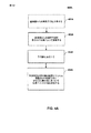
[0094]ブロック401において、復号器30は、基準層からの残差予測に重み付け係数を適用する。上において説明されるように、一般化された残差予測(GRP)は、基準層からの残差に重み付け係数を適用することができる。重み付け係数は、特定のシナリオ、例えば、単一ループ復号、に関して最適であると決定することができる。重み付け係数は、重み付け候補の数、重み付けステップ、重み付けインデックス、重み付けテーブル、等の情報を含むことができる。
[0094] In
[0095]ブロック402において、復号器30は、拡張層からの残差予測を入手する。ブロック403において、復号器30は、拡張層からの時間的予測を入手する。
[0095] At
[0096]ブロック404において、復号器30は、重み付け係数によって調整された基準層からの残差予測、拡張層からの残差予測、及び拡張層からの時間的予測に基づいて現在の映像ユニットを決定する。上において説明されるように、GRPでは、現在の映像ユニットは、方程式(3)により予測することができる。
[0096] At
[0097]図4に関して説明される本開示の態様による一般化された残差予測のための方法例は、様々なコーディングレベル、例えば、シーケンス、ピクチャ、フレームのグループ、フレーム、スライスのグループ、スライス、コーディングユニット(CU)のグループ、コーディングユニット(CU)、予測ユニット(PU)のグループ、予測ユニット(PU)、ブロック、ピクセルの領域、又はピクセル、において実装することができる。さらに、図4に関して説明される本開示の態様による一般化された残差予測のための方法例は、信号成分、例えば、ルマコンポーネント及びクロマコンポーネント、に対しても適用することができる。例えば、方法例は、ルマコンポーネントのみに対して、クロマコンポーネントのみに対して、又はルマコンポーネントとクロマコンポーネントの組み合わせ(例えば、1つのルマコンポーネントと2つのクロマコンポーネントの組み合わせ)に対して適用することができる。さらに、図4に関して説明されるすべての実施形態は、別々に、又は互いに組み合わせて実装することができる。 [0097] An example method for generalized residual prediction according to aspects of this disclosure described with respect to FIG. 4 may be performed at various coding levels, eg, sequences, pictures, groups of frames, frames, groups of slices, slices. , Coding unit (CU) group, coding unit (CU), prediction unit (PU) group, prediction unit (PU), block, pixel region, or pixel. Further, the example method for generalized residual prediction according to aspects of the present disclosure described with respect to FIG. 4 can also be applied to signal components, eg, luma and chroma components. For example, the example method may be applied to luma components only, to chroma components only, or to a combination of luma and chroma components (eg, a combination of one luma component and two chroma components). it can. Further, all embodiments described with respect to FIG. 4 can be implemented separately or in combination with each other.
[0098]図4Aは、本開示の態様による一般化された残差予測のための他の方法例を示したフローチャートである。プロセス400Aは、符号器(例えば、図2に示される符号器、等)、復号器(例えば、図3に示される復号器、等)、又はその他のコンポーネントによって実行することができる。プロセス400Aのブロックは、図3の復号器30に関して説明されるが、プロセス400Aは、上記のように、その他のコンポーネント、例えば、符号器、によって実行することができる。プロセス400Aは、SVC及び3D映像コーディングに対して適用することができる。図4Aに関して説明されるすべての実施形態は、別々に、又は互いに組み合わせて実装することができる。
[0098] FIG. 4A is a flowchart illustrating another example method for generalized residual prediction according to aspects of this disclosure.
[0099]ブロック401Aにおいて、復号器30は、基準層からの残差予測を入手する。基準層は、現在の層に関する基本層であることができる。基準層は、現在の拡張層に対応する拡張層であることもできる。基準層からの残差予測は、様々な方法で決定することができる。例えば、基準層内の共配置された映像ユニットの残差は、現在の層の解像度にマッチさせるためにアップサンプリングすることができる。
[0099] At block 401A, the
[00100]ブロック402Aにおいて、復号器30は、重み付け係数によって基準層からの残差予測を調整する。重み付け係数は、1と異なることができる。重み付け係数が1である場合は、復号器30は、伝統的な残差予測を行うことができる。重み付け係数は、重み付け情報、例えば、重み付けステップ、重み付けテーブル、重み付け係数候補の数、及び重み付けインデックス、に基づいて決定することができる。幾つかの実施形態では、重み付け係数は、ビットストリームにおいて受信することができる。その他の実施形態では、重み付け係数は、ビットストリームで受信された情報から又は以前に復号された情報から少なくとも部分的に導き出すことができる。重み付け係数は、限定されることなしに、次の構文レベルを含むあらゆるコーディングレベルでコーディングすることができる。すなわち、シーケンス、フレームのグループ、フレーム、スライスのグループ、スライス、コーディングユニット(CU)のグループ、コーディングユニット(CU)、予測ユニット(PU)のグループ、予測ユニット(PU)、ブロック、ピクセルの領域、又はピクセル及び1つのルマコンポーネントと2つのクロマコンポーネントの組み合わせ。
[00100] In
[00101]幾つかの実施形態では、重み付け情報は、ビットストリームで受信することもでき、又は、ビットストリームで受信された情報から又は以前に復号された情報から少なくとも部分的に導き出すことができる。重み付け係数は、限定されることなしに、次の構文レベルを含むあらゆるコーディングレベルでコーディングすることもできる。すなわち、シーケンス、フレームのグループ、フレーム、スライスのグループ、スライス、コーディングユニット(CU)のグループ、コーディングユニット(CU)、予測ユニット(PU)のグループ、予測ユニット(PU)、ブロック、ピクセルの領域、ピクセル、及び1つのルマコンポーネントと2つのクロマコンポーネントの組み合わせ。 [00101] In some embodiments, the weighting information can be received in the bitstream, or can be derived at least in part from information received in the bitstream or from previously decoded information. The weighting factor can be coded at any coding level including, but not limited to, the following syntax levels. Sequence, frame group, frame, slice group, slice, coding unit (CU) group, coding unit (CU), prediction unit (PU) group, prediction unit (PU), block, pixel region, A pixel and a combination of one luma component and two chroma components.
[00102]ブロック403Aにおいて、復号器30は、予測値を決定する。予測値は、現在の映像ユニットに関する予測値であることができる。幾つかの実施形態では、予測値は、現在の映像ユニットに関する予測ユニットである。予測値は、時間的予測値又は空間的イントラ予測値であることができる。プロセス400Aは、インター予測及びイントラ予測の両方とともに使用することができる。
[00102] In
[00103]ブロック404Aにおいて、復号器30は、予測値及び基準層と関連付けられた調整された残差予測に少なくとも部分的に基づいて映像ユニットの値を決定する。映像ユニットは、映像データのあらゆるユニットであることができ、及び、フレームと、スライスと、最大コーディングユニット(LCU)と、コーディングユニット(CU)と、ブロックと、ピクセルと、サブピクセルとを含むことができ、ただしこれらに限定されない。映像ユニットの値は、映像ユニットに関する予測ユニット(PU)を生成することによって決定することができる。
[00103] At
[00104]幾つかの実施形態では、復号器30は、現在の映像ユニットに関する残差予測、現在の映像ユニットに関する予測値、及び基準層と関連付けられた調整された残差予測に基づいて層内の現在の映像ユニットの値を決定することができる。現在の映像ユニットに関する残差予測及び予測値は、現在の層からであることができる。現在の映像ユニットの値は、現在の映像ユニットに関する予測値、現在の映像ユニットに関する残差予測、及び基準層と関連付けられた調整された残差予測を加えることによって決定することができる。
[00104] In some embodiments, the
[00105]図5は、本開示の態様による単一ループ復号を用いた一般化された残差予測のための方法例を示したフローチャートである。上において説明されるように、単一ループ復号では、拡張層の動き補償に関して1つのループが使用される。単一ループ復号のシナリオでは、基本層の完全な再構築は利用できない。従って、基本層の正規化された残差を基本残差予測子として直接採用することができる。拡張層に関して、再構築I^eは、次のように決定することができる。
ここで、re及びPeは、拡張層の逆量子化された残差及び時間的予測を表し、rbは、(空間的スケーラブルケースでアップサンプリングされた)正規化された基本層残差予測子を表し、rb’は、基本層残差を表し、Qe及びQbは、拡張層及び基本層のそれぞれの量子化ステップを表す。 Here, r e and P e represents the inverse quantized residual and temporal prediction of enhancement layer, r b is (upsampled spatially scalable case) normalized base layer residual Represents a predictor, r b ′ represents the base layer residual, and Q e and Q b represent the quantization steps of the enhancement layer and the base layer, respectively.
[00106]今度は、本開示の態様による単一ループ復号を用いた一般化された残差予測のための方法例が、図5を参照して説明される。プロセス500は、符号器(例えば、図2に示される符号器、等)、復号器(例えば、図3に示される復号器、等)、又はその他のコンポーネントによって実行することができる。プロセス500のブロックは、図3の復号器30に関して説明されるが、プロセス500は、上記のように、その他のコンポーネント、例えば、符号器、によって実行することができる。ブロック501において、復号器30は、GRPフレームワークに関する単一ループ復号における基準層からの残差予測に関する重み付け係数を決定する。ブロック502において、復号器30は、重み付け係数によって調整されたRLからの残差予測、ELからの残差予測、及びELからの時間的予測に基づいて現在の映像ユニットを決定する。例えば、方程式(4)に関して上述されるように、正規化された基本層残差は、RL残差予測のために使用することができる。図5に関して説明される本開示の態様による単一ループ復号を用いた一般化された残差予測のための方法例は、様々なコーディングレベル、例えば、シーケンス、ピクチャ、フレームのグループ、フレーム、スライスのグループ、スライス、コーディングユニット(CU)のグループ、コーディングユニット(CU)、予測ユニット(PU)のグループ、予測ユニット(PU)、ブロック、ピクセルの領域、又はピクセル、において実装することができる。さらに、図5に関して説明される本開示の態様による一般化された残差予測のための方法例は、信号成分、例えば、ルマコンポーネント及びクロマコンポーネント、に対しても適用することができる。例えば、方法例は、ルマコンポーネントのみに対して、クロマコンポーネントのみに対して、又はルマコンポーネントとクロマコンポーネントの組み合わせ(例えば、1つのルマコンポーネントと2つのクロマコンポーネントの組み合わせ)に対して適用することができる。さらに、図5に関して説明されるすべての実施形態は、別々に、又は互いに組み合わせて実装することができる。
[00106] An example method for generalized residual prediction using single loop decoding in accordance with aspects of the present disclosure will now be described with reference to FIG.
[00107]図6は、本開示の態様による多ループ復号を用いた一般化された残差予測のための方法例を示したフローチャートである。上において説明されるように、多ループ復号では、多ループは、拡張層の動き補償のために使用される。多ループ復号のシナリオでは、拡張層を符号化/復号するときに基本層の完全な再構築を利用可能である。従って、以前にコーディングされた拡張層と基本層(必要な場合はアップサンプリングされた)の再構築の間の差分値を残差予測子として採用することができる。拡張層に関して、再構築I^eは、次のように決定することができる。
ここで、reは、拡張層における現在の映像ユニットの逆量子化された残差を示し、Pe及びPbは、拡張層及び基本層のそれぞれにおける現在の映像ユニットに関する時間的予測を示し、I^bは、基本層における現在の映像ユニットの完全な再構築を示す。拡張層及び基本層は、品質に関して異なる目標を有するため、時間的予測Pe及びPbの動きは異なることができる。 Here, r e indicates the inverse quantized residual of the current video unit in the enhancement layer, and P e and P b indicate temporal predictions for the current video unit in the enhancement layer and the base layer, respectively. , I ^ b indicates a complete reconstruction of the current video unit in the base layer. Since the enhancement layer and the base layer have different goals for quality, the temporal predictions P e and P b movement can be different.
[00108]基本層及び拡張層が同じ動きを有する場合は、時間的予測Pe及びPbの動きは同じであり、方程式(5)を直接採用することができる。拡張層のインター映像ユニットを復号するときには、それの拡張層及び基本層の時間的予測Pe及びPbの両方を利用可能である。基本層再構築I^bも利用可能である。従って、再構築I^eは、逆量子化された残差re及びwから入手することができ、それらは、図7及び8に関してより詳細に説明されるようにシグナリングもすること又は導き出すことができる。同様に、GRPフレームワークをイントラCUに適用時には、Pe及びPbは、拡張層及び基本層のそれぞれにおける現在の映像ユニットに関する空間イントラ予測を示す。さらに、Pe及びPbは、同じイントラ予測方向を適用することによって入手することができ、それは、Pe及びPbの同じ動きを仮定することができるインター予測事例と同様である。 [00108] If the base layer and the enhancement layer have the same motion, the same motion of the temporal prediction P e and P b, it can be employed equation (5) directly. When decoding the inter-picture unit of the expansion layer is available both temporal prediction P e and P b of its expanded layer and the base layer. Base layer reconstruction I ^ b is also available. Thus, the reconstruction I ^ e can be obtained from the dequantized residuals r e and w, which also signal or derive as described in more detail with respect to FIGS. Can do. Similarly, when applied to GRP framework intra CU, P e and P b indicate the spatial intra prediction for the current video unit in each of the enhancement layer and base layer. Furthermore, P e and P b can be obtained by applying the same intra prediction direction, which is similar to the inter prediction case where the same motion of P e and P b can be assumed.
[00109]基本層及び拡張層が異なる動きを有する場合は、拡張層及び基本層の時間的予測Pe及びPbが異なり、基本層の残差及び拡張層の残差は相関させることができない。該事例では、残差予測は良い結果に結び付かないことがある。残差予測の性能を向上させるために、拡張層及び基本層の時間的予測は同じ動きを共有すると仮定することができる。EL及びBLの時間的予測が同じ動きを共有すると仮定することに加えて又は仮定する代わりに、残差予測子を生成するために基本層の動き又は拡張層の動きのいずれかを強制的に他の層に適用することができる。例えば、拡張層の時間的予測Peの動きは、Pbを得るために基本層に適用することができる。該事例では、Pe及びPbの両方ともPeの動きによって生成することができるため、拡張層を復号するために2つの動き補償がしばしば使用される。 [00109] If the base layer and the enhancement layer has a different motion, different temporal predictions P e and P b of the enhancement layer and base layer, the residual of the residual and enhancement layer of the base layer can not be correlated . In such cases, residual prediction may not lead to good results. In order to improve the performance of residual prediction, it can be assumed that the temporal and base layer temporal predictions share the same motion. In addition to or instead of assuming that EL and BL temporal predictions share the same motion, force either base layer motion or enhancement layer motion to generate a residual predictor It can be applied to other layers. For example, the movement of the temporal prediction P e of the expansion layer can be applied to the base layer in order to obtain a P b. In that case, two motion compensations are often used to decode the enhancement layer, since both P e and P b can be generated by the movement of P e .
[00110]今度は、本開示の態様による多ループ復号を用いる一般化された残差予測のための方法例が、図6を参照して説明される。プロセス600は、符号器(例えば、図2に示される符号器、等)、復号器(例えば、図3に示される復号器、等)、又はその他のコンポーネントによって実行することができる。プロセス600のブロックは、図3の復号器30に関して説明されるが、プロセス600は、上記のように、その他のコンポーネント、例えば、符号器、によって実行することができる。ブロック601において、復号器30は、GRPフレームワークに関する多ループ復号における基準層からの残差予測に関する重み付け係数を決定する。ブロック602において、復号器30は、重み付け係数によって調整されたRLからの残差予測、ELからの残差予測、及びELからの時間的予測に基づいて現在の映像ユニットを決定する。例えば、上において方程式(5)に関して説明されるように、RL残差予測に関してはI^b−Pbを使用することができる。図6に関して説明される本開示の態様による多ループ復号を用いる一般化された残差予測のための方法例は、様々なコーディングレベル、例えば、シーケンス、ピクチャ、フレームのグループ、フレーム、スライスのグループ、スライス、コーディングユニット(CU)のグループ、コーディングユニット(CU)、予測ユニット(PU)のグループ、予測ユニット(PU)、ブロック、ピクセルの領域、又はピクセル、において実装することができる。さらに、図6に関して説明される本開示の態様による一般化された残差予測のための方法例は、信号成分、例えば、ルマコンポーネント及びクロマコンポーネント、に対しても適用することができる。例えば、方法例は、ルマコンポーネントのみに対して、クロマコンポーネントのみに対して、又はルマコンポーネントとクロマコンポーネントの組み合わせ(例えば、1つのルマコンポーネントと2つのクロマコンポーネントの組み合わせ)に対して適用することができる。さらに、図6に関して説明されるすべての実施形態は、別々に、又は互いに組み合わせて実装することができる。
[00110] An example method for generalized residual prediction using multi-loop decoding according to aspects of this disclosure will now be described with reference to FIG.
[00111]図7は、本開示の態様による一般化された残差予測パラメータをシグナリングするための方法例を示したフローチャートである。上において説明されるように、重み付け情報は、重み付け候補の数と、重み付けステップ(又は重み付けテーブル)と、重み付けインデックスと、を含むことができる。重み付け係数wは、該重み付け情報に基づいて決定することができる。重み付け候補の数は、Nwによって表すことができる。重み付けステップは、Swによって、及び重み付けテーブルはWTによって表すことができる。重み付けインデックスは、iwによって表すことができる。一実施形態では、重み付け係数wは、次のように重み付けステップSw及び重み付けインデックスiwに基づいて導き出される。
他の実施形態では、wは、インデックスiwによりルックアップテーブルWTから入手することができる。 In other embodiments, w can be obtained from the look-up table W T by index i w .
[00112]重み付け係数情報は、限定されることになしに、Nw、Sw、WT、及びiwを含むことができ、様々な方法でシグナリングすることができる。幾つかの実施形態では、重み付けステップSw又は重み付けテーブルWTは、ハードコーディング又はシグナリングすることができる。Sw又はWTは、シーケンスレベル又はピクチャレベルでシグナリングすることができる。重み付けインデックスiwは、それよりも低いレベル、例えば、CU及びPU、でシグナリングすることができる。 [00112] The weighting factor information may include, without limitation, N w , S w , W T , and i w and may be signaled in various ways. In some embodiments, the weighting step S w or the weighting table W T can be hard coded or signaled. S w or W T can be signaled at the sequence level or the picture level. The weighting index i w can be signaled at lower levels, eg, CU and PU.
[00113]一実施形態では、重み付けステップSwは、3ビット量子化(Swは、1/8、2/8、...、8/8であることができる)及びシーケンスパラメータセット(SPS)内でコーディングされた符号なし整数Exp−Golombによって表される。Nw≧1であることを考慮すると、(Nw−1)もSPS内でコーディングされた符号なし整数Exp−Golombである。重み付けインデックスiwは、最初に、打ち切られたunaryコード(Nwが最大数)でバイナリ化され、次に、CABACコーディングされる。CABACコーディングでは、最初のビンは、1つのコンテキストでコーディングされ、残りのビンは他のコンテキストでコーディングされる。重み付けインデックスiwをコーディングするために、コンテキストは、以前にコーディングされたパラメータに依存することができる。例えば、空間的に隣接するCU、例えば、左及び上のCU、のiwを、現在のCUの重み付けインデックスiwに関するコンテキストとして使用することができる。さらに、現在のCUのタイプ、例えば、現在のCUがスキップ又はマージコーディングされるか、又は現在のCUのサイズをコンテキストとして使用することができる。 [00113] In one embodiment, the weighting step S w includes 3 bit quantization (S w can be 1/8, 2/8, ..., 8/8) and a sequence parameter set (SPS). ) Is represented by an unsigned integer Exp-Golomb coded within. Considering N w ≧ 1, (N w −1) is also an unsigned integer Exp-Golomb coded in the SPS. The weighting index i w is first binarized with a truncated unary code (where N w is the maximum number) and then CABAC coded. In CABAC coding, the first bin is coded in one context and the remaining bins are coded in another context. To code the weighting index i w, context can be dependent on the coded previously parameters. For example, i w of spatially adjacent CUs, eg, left and top CUs, can be used as context for the current CU's weighting index i w . Further, the current CU type, eg, the current CU can be skipped or merge coded, or the current CU size can be used as context.
[00114]その他の実施形態では、異なるCUモードは、異なる重み付け係数シグナリング法を有することができる。例えば、スキップ及びマージモードに関しては、3つの重み付け係数(例えば、w=0、w=0.5、及びw=1)を選択してシグナリングすることができる。スキップ及びマージモード以外のインターモードに関しては、2つの重み付け係数(例えば、w=0及びw=1)のみを選択してシグナリングすることができる。代替として、スキップ及びマージモード以外のインターモードに関しては、1つの固定された重み付け係数のみを適用することができる。該事例では、重み付け係数に関する追加のシグナリングは使用することができない。 [00114] In other embodiments, different CU modes may have different weighting factor signaling methods. For example, for skip and merge modes, three weighting factors (eg, w = 0, w = 0.5, and w = 1) can be selected and signaled. For inter modes other than skip and merge modes, only two weighting factors (eg, w = 0 and w = 1) can be selected and signaled. Alternatively, for inter modes other than skip and merge modes, only one fixed weighting factor can be applied. In this case, no additional signaling regarding the weighting factor can be used.
[00115]今度は、本開示の態様による一般化された残差予測パラメータをシグナリングするための方法例が、図7を参照して説明される。プロセス700は、符号器(例えば、図2に示される符号器、等)、復号器(例えば、図3に示される復号器、等)、又はその他のコンポーネントによって実行することができる。プロセス700のブロックは、図2の符号器20に関して説明されるが、プロセス700は、上記のように、その他のコンポーネント、例えば、復号器、によって実行することができる。ブロック701において、符号器20は、重み付けステップ又は重み付けテーブルをシグナリングする。ブロック702において、符号器20は、重み付け候補の数をシグナリングする。ブロック703において、符号器20は、重み付けインデックスをシグナリングする。プロセス700におけるブロックは、異なる順序で行うことができる。例えば、重み付け候補の数は、重み付けステップ(又は重み付けテーブル)の前にシグナリングすることができる。図7に関して説明される本開示の態様による一般化された残差予測パラメータをシグナリングするための方法例は、様々なコーディングレベル、例えば、シーケンス、ピクチャ、フレームのグループ、フレーム、スライスのグループ、スライス、コーディングユニット(CU)のグループ、コーディングユニット(CU)、予測ユニット(PU)のグループ、予測ユニット(PU)、ブロック、ピクセルの領域、又はピクセル、において実装することができる。さらに、図7に関して説明される本開示の態様による一般化された残差予測のための方法例は、信号成分、例えば、ルマコンポーネント及びクロマコンポーネント、に対しても適用することができる。例えば、方法例は、ルマコンポーネントのみに対して、クロマコンポーネントのみに対して、又はルマコンポーネントとクロマコンポーネントの組み合わせ(例えば、1つのルマコンポーネントと2つのクロマコンポーネントの組み合わせ)に対して適用することができる。さらに、図7に関して説明されるすべての実施形態は、別々に、又は互いに組み合わせて実装することができる。
[00115] An example method for signaling generalized residual prediction parameters in accordance with aspects of this disclosure will now be described with reference to FIG.
[00116]図8は、本開示の態様による一般化された残差予測パラメータを導き出すための方法例を示したフローチャートである。GRPパラメータは、図7に関して説明されるようにシグナリングすることができる。GRPパラメータは、ビットストリームに含まれる情報から導き出すこともできる。GRPパラメータは、ビットストリーム内の情報から完全に又は部分的に導き出すことができる。一実施形態では、重み付けステップSwは、関連するCUサイズによりCUレベルで導き出される。重み付けステップSwとCUサイズとの間のマッピング例が下表において示される。
[00117]他の実施形態では、重み付け候補の最大数は、以前にコーディングされた情報、例えば、CUモード、CUサイズ、及び量子化に基づいてCUレベルで調整される。例えば、16×16よりも小さいCUに関しては、例えば、シグナリングコストを節約するために、2つの重み付け候補のみを許容することができる。 [00117] In other embodiments, the maximum number of weighting candidates is adjusted at the CU level based on previously coded information, eg, CU mode, CU size, and quantization. For example, for CUs smaller than 16 × 16, only two weighting candidates can be allowed, eg, to save signaling costs.
[00118]今度は、本開示の態様による一般化された残差予測パラメータを導き出すための方法例が、図8を参照して説明される。プロセス800は、符号器(例えば、図2に示される符号器、等)、復号器(例えば、図3に示される復号器、等)、又はその他のコンポーネントによって実行することができる。プロセス800のブロックは、図3の復号器30に関して説明されるが、プロセス800は、上記のように、その他のコンポーネント、例えば、符号器、によって実行することができる。
[00118] An example method for deriving generalized residual prediction parameters according to aspects of the present disclosure will now be described with reference to FIG.
[00119]ブロック801において、復号器30は、重み付け情報を決定するためにビットストリームから情報を入手するか又は以前にコーディングされた情報を入手する。例えば、上において説明されるように、GRPパラメータは、CUサイズに基づくことができる。又は、GRPパラメータは、以前にコーディングされた情報、例えば、CUモード、CUサイズ、及び量子化に基づくことができる。ブロック802において、復号器30は、ブロック801において入手された情報に基づいて一般化された残差予測に関する1つ以上のパラメータを決定する。例えば、復号器30は、CUサイズに基づいて重み付けステップSwを決定することができる。復号器30は、CUサイズに基づいて重み付け候補の数Nwを決定することもできる。復号器30は、以前にコーディングされた情報、例えば、CUモード、CUサイズ、及び量子化に基づいて重み付け情報を調整することもできる。図8に関して説明される本開示の態様による一般化された残差予測のための方法例は、様々なコーディングレベル、例えば、シーケンス、ピクチャ、フレームのグループ、フレーム、スライスのグループ、スライス、コーディングユニット(CU)のグループ、コーディングユニット(CU)、予測ユニット(PU)のグループ、予測ユニット(PU)、ブロック、ピクセルの領域、又はピクセル、において実装することができる。さらに、図8に関して説明される本開示の態様による一般化された残差予測パラメータを導き出すための方法例は、信号成分、例えば、ルマコンポーネント及びクロマコンポーネント、に対しても適用することができる。例えば、方法例は、ルマコンポーネントのみに対して、クロマコンポーネントのみに対して、又はルマコンポーネントとクロマコンポーネントの組み合わせ(例えば、1つのルマコンポーネントと2つのクロマコンポーネントの組み合わせ)に対して適用することができる。さらに、図8に関して説明されるすべての実施形態は、別々に、又は互いに組み合わせて実装することができる。
[00119] At
[00120]図9は、本開示の態様による一般化された残差予測において層をアップサンプリング又はダウンサンプリングするための方法例を示したフローチャートである。層間予測プロセスにおいて、拡張層の空間アスペクト比をマッチさせるためにアップサンプリング又はダウンサンプリングフィルタリングプロセスが基本層ピクチャに適用される。フィルタリングプロセス、例えば、平滑化フィルタ、は、基本層及び拡張層のピクチャサイズが同一であるときでさえも適用することができる。概して、1つの固定されたアップサンプリング、ダウンサンプリング、及び平滑化フィルタセットが使用され及びハードコーディングされる。フィルタは、分数的ピクセルシフト(位相と時々呼ばれる)によりセットから選択することができ、それは、基本層ピクチャと拡張層ピクチャとの間の空間アスペクト比に基づいて計算される。 [00120] FIG. 9 is a flowchart illustrating an example method for upsampling or downsampling a layer in generalized residual prediction according to aspects of this disclosure. In the interlayer prediction process, an upsampling or downsampling filtering process is applied to the base layer picture to match the spatial aspect ratio of the enhancement layer. A filtering process, such as a smoothing filter, can be applied even when the base layer and enhancement layer picture sizes are the same. In general, one fixed upsampling, downsampling, and smoothing filter set is used and hardcoded. The filter can be selected from the set by fractional pixel shift (sometimes called phase), which is calculated based on the spatial aspect ratio between the base layer picture and the enhancement layer picture.
[00121]GRPフレームワークでは、層間予測性能を向上させるために異なるタイミングセットを適用することができる。フィルタリングセットは、シーケンス又はピクチャレベルでハードコーディング又はシグナリングすることができる。フィルタセットインデックスは、それよりも低いレベル、例えば、CU及びPU、でシグナリングすること又は導き出すことができる。フィルタセットインデックスは、重み付け係数wの値に基づいて導き出すことができ、又は重み付けインデックスiwの値に基づいて導き出すことができる。フィルタリングセットインデックスと重み付け係数wとの間、又はフィルタリングセットと重み付けインデックスiwとの間の導出マッピングテーブルは、シーケンス又はピクチャレベルでハードコーディング又はシグナリングすることができる。 [00121] In the GRP framework, different timing sets can be applied to improve inter-layer prediction performance. The filtering set can be hard coded or signaled at the sequence or picture level. The filter set index can be signaled or derived at a lower level, eg, CU and PU. Filter set index can be derived based on the value of the weighting factor w, or may be derived based on the value of the weighting index i w. The derived mapping table between the filtering set index and the weighting factor w or between the filtering set and the weighting index i w can be hard coded or signaled at the sequence or picture level.
[00122]今度は、本開示の態様による一般化された残差予測において層をアップサンプリング又はダウンサンプリングするための方法例が、図9を参照して説明される。プロセス900は、符号器(例えば、図2に示される符号器、等)、復号器(例えば、図3に示される復号器、等)、又はその他のコンポーネントによって実行することができる。プロセス900のブロックは、図3の復号器30に関して説明されるが、プロセス900は、上記のように、その他のコンポーネント、例えば、符号器、によって実行することができる。
[00122] An example method for upsampling or downsampling a layer in generalized residual prediction according to aspects of the present disclosure will now be described with reference to FIG. Process 900 may be performed by an encoder (eg, the encoder shown in FIG. 2, etc.), a decoder (eg, the decoder shown in FIG. 3, etc.), or other component. Although the blocks of process 900 are described with respect to
[00123]ブロック901において、復号器30は、基準層をアップサンプリングするか又は拡張層をダウンサンプリングするかを決定する。空間スケーラビリティにおいて、該アップサンプリング及びダウンサンプリングは、層間予測を同じ分解能で行うことができるようにするために実施される。ブロック902において基準層がアップサンプリングされると決定された場合は、復号器30は、ブロック903において基準層を拡張層の分解能にアップサンプリングする。他方、復号器30は、ブロック904において拡張層を基準層の分解能にダウンサンプリングする。ブロック905において、復号器30は、アップサンプリングされた又はダウンサンプリングされたピクチャに平滑化フィルタを適用する。平滑化フィルタは、拡張層ピクチャ及び基準層ピクチャが同じである場合でも適用することができる。平滑化フィルタは、適宜選択することができる。ブロック906において、復号器30は、アップサンプリング又はダウンサンプリングされたピクチャに基づいてGRPを用いて現在の映像ユニットを決定する。
[00123] At
[00124]図9に関して説明される本開示の態様による一般化された残差予測において層をアップサンプリング又はダウンサンプリングするための方法例は、様々なコーディングレベル、例えば、シーケンス、ピクチャ、フレームのグループ、フレーム、スライスのグループ、スライス、コーディングユニット(CU)のグループ、コーディングユニット(CU)、予測ユニット(PU)のグループ、予測ユニット(PU)、ブロック、ピクセルの領域、又はピクセル、において実装することができる。さらに、図9に関して説明される本開示の態様による一般化された残差予測に層をアップサンプリング又はダウンサンプリングするための方法例は、信号成分、例えば、ルマコンポーネント及びクロマコンポーネント、に対しても適用することができる。例えば、方法例は、ルマコンポーネントのみに対して、クロマコンポーネントのみに対して、又はルマコンポーネントとクロマコンポーネントの組み合わせ(例えば、1つのルマコンポーネントと2つのクロマコンポーネントの組み合わせ)に対して適用することができる。さらに、図9に関して説明されるすべての実施形態は、別々に、又は互いに組み合わせて実装することができる。 [00124] An example method for upsampling or downsampling a layer in generalized residual prediction according to aspects of the present disclosure described with respect to FIG. 9 is a group of different coding levels, eg, sequences, pictures, frames. Implemented in a frame, a group of slices, a slice, a group of coding units (CU), a coding unit (CU), a group of prediction units (PU), a prediction unit (PU), a block, a region of pixels, or a pixel Can do. Furthermore, example methods for upsampling or downsampling layers to generalized residual prediction according to aspects of the disclosure described with respect to FIG. 9 are also provided for signal components, eg, luma and chroma components Can be applied. For example, the example method may be applied to luma components only, to chroma components only, or to a combination of luma and chroma components (eg, a combination of one luma component and two chroma components). it can. Furthermore, all embodiments described with respect to FIG. 9 can be implemented separately or in combination with each other.
[00125]図10は、本開示の態様による一般化された残差予測において動き情報を再マッピング、アップサンプリング、又はダウンサンプリングするための方法例を示したフローチャートである。幾つかの事例では、残差予測子を生成するために1つの層の動き情報を他の層に適用するときには、1つの層において利用可能な基準が他の層では利用できないことがある。該場合は、動きの再マッピングが必要である。一実施形態では、基準が1つの層でしか利用可能でない場合は、この基準が提案されるGRPフレームワークにおいて残差予測子を生成するために使用されないようにするために利用不能と表示される。他の実施形態では、利用不能な基準が関連する基準リストの初めの基準によって取って代わられ、動きがゼロの動きに設定される。 [00125] FIG. 10 is a flowchart illustrating an example method for remapping, upsampling, or downsampling motion information in generalized residual prediction according to aspects of this disclosure. In some cases, when one layer of motion information is applied to another layer to generate a residual predictor, the criteria available in one layer may not be available in the other layer. In this case, motion remapping is necessary. In one embodiment, if a criterion is only available in one layer, it is indicated as unavailable to prevent this criterion from being used to generate a residual predictor in the proposed GRP framework. . In other embodiments, the unavailable criteria are replaced by the first criteria in the relevant criteria list and the motion is set to zero motion.
[00126]3D映像コーディングにおいて、SVC映像データは、異なるビューに関する映像データも含む。ビューは、異なる角度に関連することができるため、これらの異なるビュー間で差異が存在することがある。3D映像コーディングに関して動きが再マッピングされる場合は、動きを再マッピングする際に差異ベクトル(disparity vector)を考慮することができる。 [00126] In 3D video coding, SVC video data also includes video data for different views. Because views can be related to different angles, there may be differences between these different views. If motion is remapped for 3D video coding, a disparity vector can be considered when remapping the motion.
[00127]空間スケーラブルな事例では、拡張層と基本層との間での異なる分解能に起因して動きベクトルをアップサンプリン又はダウンサンプリングすることができる。一実施形態では、動きベクトルスケーリングは、分解能比に直接基づく。他の実施形態では、直接スケーリングに引き続いて追加の移相(+1又は−1)を適用することができる。追加の移相は、ビットストリームにおいてシグナリングすること又は以前にコーディングされた情報、例えば、PUサイズ、動きベクトル、CU深度、等、に基づいて導き出すことができる。 [00127] In the spatial scalable case, motion vectors can be upsampled or downsampled due to different resolutions between the enhancement layer and the base layer. In one embodiment, motion vector scaling is directly based on the resolution ratio. In other embodiments, an additional phase shift (+1 or −1) can be applied following direct scaling. Additional phase shifts can be derived based on signaling in the bitstream or based on previously coded information, eg, PU size, motion vector, CU depth, etc.
[00128]今度は、本開示の態様による動き情報を再マッピング、アップサンプリング、又はダウンサンプリングするための方法例が、図10を参照して説明される。プロセス1000は、符号器(例えば、図2に示される符号器、等)、復号器(例えば、図3に示される復号器、等)、又はその他のコンポーネントによって実行することができる。プロセス1000のブロックは、図3の復号器30に関して説明されるが、プロセス1000は、上記のように、その他のコンポーネント、例えば、符号器、によって実行することができる。ブロック1001において、動き情報に関する基準が層のうちの1つにおいて利用可能でない場合は、復号器30は、ブロック1002において動き情報を再マッピングする。例えば、復号器30は、他の層内の対応する基準が利用不能である場合は、その基準を利用不能と表示することができる。又は、復号器30は、関連する基準リスト内の基準への参照を再マッピングすることができる。ブロック1001においてインター予測のために使用される層内において動き情報に関する基準が利用可能である場合は、復号器30は、ブロック1003に示されるさらなる処理を行うことができない。ブロック1004において、空間SVCが使用される場合は、復号器30は、ブロック1005において、基準層動き情報をアップサンプリングするか又は拡張層動き情報をダウンサンプリングするかを決定する。空間スケーラビリティが使用されない場合は、復号器30は、ブロック1006において示されるさらなる処理を行うことができない。ブロック1007において、基準層動き情報がアップサンプリングされることが決定された場合は、復号器30は、ブロック1008において、基準層動き情報を拡張層の分解能にアップサンプリングする。他方、ブロック1007において、拡張層動き情報がダウンサンプリングされることが決定された場合は、復号器30は、ブロック1009において、拡張層動き情報を基準層の分解能にダウンサンプリングする。ブロック1010において、復号器30は、アップサンプリング又はダウンサンプリングされたピクチャを用いてGRPを用いて現在の映像ユニットを決定する。
[00128] An example method for re-mapping, up-sampling, or down-sampling motion information according to aspects of this disclosure will now be described with reference to FIG.
[00129]図10に関して説明される本開示の態様による動き情報を再マッピング、アップサンプリング、又はダウンサンプリングするための方法例は、様々なコーディングレベル、例えば、シーケンス、ピクチャ、フレームのグループ、フレーム、スライスのグループ、スライス、コーディングユニット(CU)のグループ、コーディングユニット(CU)、予測ユニット(PU)のグループ、予測ユニット(PU)、ブロック、ピクセルの領域、又はピクセル、において実装することができる。さらに、図10に関して説明される本開示の態様による一般化された残差予測のための方法例は、信号成分、例えば、ルマコンポーネント及びクロマコンポーネント、に対しても適用することができる。例えば、方法例は、ルマコンポーネントのみに対して、クロマコンポーネントのみに対して、又はルマコンポーネントとクロマコンポーネントの組み合わせ(例えば、1つのルマコンポーネントと2つのクロマコンポーネントの組み合わせ)に対して適用することができる。さらに、図10に関して説明されるすべての実施形態は、別々に、又は互いに組み合わせて実装することができる。 [00129] Example methods for remapping, up-sampling, or down-sampling motion information according to aspects of the disclosure described with respect to FIG. 10 are available at various coding levels, eg, sequences, pictures, groups of frames, frames, It can be implemented in a group of slices, a slice, a group of coding units (CU), a coding unit (CU), a group of prediction units (PU), a prediction unit (PU), a block, a region of pixels, or a pixel. Furthermore, the example method for generalized residual prediction according to aspects of the present disclosure described with respect to FIG. 10 can also be applied to signal components, eg, luma and chroma components. For example, the example method may be applied to luma components only, to chroma components only, or to a combination of luma and chroma components (eg, a combination of one luma component and two chroma components). it can. Further, all embodiments described with respect to FIG. 10 can be implemented separately or in combination with each other.
[00130]図11は、本開示の態様により一般化された残差予測において符号化するための重み付け係数を決定するための方法例を示したフローチャートである。方法例は、符号器側の最適化に適用することができる。一実施形態では、各重み付け係数候補に関してCUレート−歪みコストを検査することによって各CUに関する最良の重み付け係数wが決定される。最低のコストを有する重み付け係数が、CUに関する重み付け係数wとして選択される。他の実施形態では、残差予測子は、拡張層時間的予測Peの動きを基本層時間的予測Pbに適用することによって導き出される。重み付け係数wは、次のように決定することができる。
ここで、Iは、拡張層に関するソースピクチャを示し、
は、微分ブロック(I−Pe)及び(I^b−Pb)のドット積の和を示す。 Indicates the sum of dot products of the differential blocks (I-P e ) and (I ^ b -P b ).
[00131]今度は、本開示の態様による一般化された残差予測において符号化のための重み付け係数を決定するための方法例が、図11を参照して説明される。プロセス1100は、符号器(例えば、図2に示される符号器、等)、復号器(例えば、図3に示される復号器、等)、又はその他のコンポーネントによって実行することができる。プロセス1100のブロックは、図2の符号器20に関して説明されるが、プロセス1100は、上記のように、その他のコンポーネント、例えば、復号器、によって実行することができる。ブロック1101において、映像符号器20は、ELの時間的予測の動きをBLの時間的予測に適用することによってEL残差予測を導き出す。ブロック1102において、復号器30は、導き出された残差予測に基づいて重み付け係数を導き出す。図11に関して説明される本開示の態様による一般化された残差予測において符号化のための重み付け係数を決定するための方法例は、様々なコーディングレベル、例えば、シーケンス、ピクチャ、フレームのグループ、フレーム、スライスのグループ、スライス、コーディングユニット(CU)のグループ、コーディングユニット(CU)、予測ユニット(PU)のグループ、予測ユニット(PU)、ブロック、ピクセルの領域、又はピクセル、において実装することができる。さらに、図11に関して説明される本開示の態様による一般化された残差予測のための方法例は、信号成分、例えば、ルマコンポーネント及びクロマコンポーネント、に対しても適用することができる。例えば、方法例は、ルマコンポーネントのみに対して、クロマコンポーネントのみに対して、又はルマコンポーネントとクロマコンポーネントの組み合わせ(例えば、1つのルマコンポーネントと2つのクロマコンポーネントの組み合わせ)に対して適用することができる。さらに、図11に関して説明されるすべての実施形態は、別々に、又は互いに組み合わせて実装することができる。
[00131] An example method for determining weighting factors for encoding in generalized residual prediction according to aspects of this disclosure will now be described with reference to FIG.
[00132]例に依存して、ここにおいて説明されるいずれかの技法の幾つかの行為又はイベントは、異なるシーケンスで行うことができ、追加すること、結合すること、又はまったく省くことができる(例えば、技法を実践するためにすべての行為又はイベントが必要なわけではない)ことが認識されるべきである。さらに、幾つかの例では、行為又はイベントは、順次ではなく、同時並行して、例えば、マルチスレッド処理、割り込み処理、又は複数のプロセッサ、を通じで行うことができる。 [00132] Depending on the example, some acts or events of any of the techniques described herein can be performed in different sequences and can be added, combined, or omitted at all ( For example, it should be appreciated that not all acts or events are necessary to practice the technique. Further, in some examples, actions or events can occur in parallel rather than sequentially, for example, through multi-threaded processing, interrupt processing, or multiple processors.
[0133]1つ以上の例において、説明される機能は、ハードウェア、ソフトウェア、ファームウェア、又はそれらのあらゆる組み合わせにおいて実装することができる。ソフトウェアにおいて実装される場合は、それらの機能は、コンピュータによって読み取り可能な媒体において1つ以上の命令又はコードとして格納又は送信すること及びハードウェアに基づく処理ユニットによって実行することができる。コンピュータによって読み取り可能な媒体は、コンピュータによって読み取り可能な記憶媒体を含むことができ、それは、有形な媒体、例えば、データ記憶媒体、又は、例えば、通信プロトコルにより、1つの場所から他へのコンピュータプログラムの転送を容易にするあらゆる媒体を含む通信媒体、に対応する。このように、コンピュータによって読み取り可能な媒体は、概して、(1)非一時的である有形なコンピュータによって読み取り可能な記憶媒体又は(2)通信媒体、例えば、信号又は搬送波、に対応することができる。データ記憶媒体は、本開示において説明される技法の実装のために命令、コード及び/又はデータ構造を取り出すために1つ以上のコンピュータ又は1つ以上のプロセッサによってアクセスすることができるあらゆる利用可能な媒体であることができる。コンピュータプログラム製品は、コンピュータによって読み取り可能な媒体を含むことができる。 [0133] In one or more examples, the functions described can be implemented in hardware, software, firmware, or any combination thereof. If implemented in software, the functions may be stored or transmitted as one or more instructions or code on a computer-readable medium and executed by a hardware-based processing unit. The computer readable medium can include a computer readable storage medium, which can be a tangible medium, eg, a data storage medium, or a computer program from one place to another, eg, via a communication protocol. It supports communication media including any media that facilitates the transfer of data. In this manner, computer-readable media generally may correspond to (1) tangible computer-readable storage media which is non-transitory or (2) a communication medium such as a signal or carrier wave. . A data storage medium may be any available that can be accessed by one or more computers or one or more processors to retrieve instructions, code, and / or data structures for implementation of the techniques described in this disclosure. It can be a medium. The computer program product can include a computer-readable medium.
[00134]一例により、及び制限することなしに、該コンピュータによって読み取り可能な記憶媒体は、希望されるプログラムコードを命令又はデータ構造の形態で格納するために使用することができ及びコンピュータによってアクセス可能であるRAM、ROM、EEPROM、CD−ROM又はその他の光学ディスク記憶装置、磁気ディスク記憶装置、又はその他の磁気記憶デバイス、フラッシュメモリ、又はその他のいずれかの媒体を備えることができる。さらに、どのような接続も、コンピュータによって読み取り可能な媒体であると適切に呼ばれる。例えば、命令が、同軸ケーブル、光ファイバケーブル、より対線、デジタル加入者ライン(DSL)、又は無線技術、例えば、赤外線、無線、及びマイクロ波、を用いてウェブサイト、サーバ、又はその他の遠隔ソースから送信される場合は、該同軸ケーブル、光ファイバケーブル、より対線、DSL、又は無線技術、例えば赤外線、無線、及びマイクロ波、は、媒体の定義の中に含まれる。しかしながら、コンピュータによって読み取り可能な記憶媒体およびデータ記憶媒体は、コネクション、搬送波、信号、又はその他の遷移媒体は含まず、代わりに、非一時的な、有形の記憶媒体を対象とすることが理解されるべきである。ここにおいて用いられるときのディスク(disk及びdisc)は、コンパクトディスク(CD)(disc)と、レーザディスク(disc)と、光ディスク(disc)と、デジタルバーサタイルディスク(DVD)(disc)と、フロッピー(登録商標)ディスク(disk)と、ブルーレイ(登録商標)ディスク(disc)と、を含み、ここで、diskは、通常は磁気的にデータを複製し、discは、レーザを用いて光学的にデータを複製する。上記の組み合わせも、コンピュータによって読み取り可能な媒体の適用範囲内に含められるべきである。 [00134] By way of example and without limitation, the computer-readable storage medium can be used to store the desired program code in the form of instructions or data structures and is accessible by the computer. A RAM, ROM, EEPROM, CD-ROM or other optical disk storage, magnetic disk storage, or other magnetic storage device, flash memory, or any other medium. In addition, any connection is properly referred to as a computer-readable medium. For example, instructions may be directed to a website, server, or other remote using coaxial cable, fiber optic cable, twisted pair, digital subscriber line (DSL), or wireless technology such as infrared, wireless, and microwave. When transmitted from a source, the coaxial cable, fiber optic cable, twisted pair, DSL, or wireless technologies such as infrared, wireless, and microwave are included in the definition of the medium. However, it is understood that computer-readable storage media and data storage media do not include connections, carrier waves, signals, or other transition media, but instead cover non-transitory, tangible storage media. Should be. As used herein, the discs (disk and disc) include a compact disc (CD) (disc), a laser disc (disc), an optical disc (disc), a digital versatile disc (DVD) (disc), and a floppy ( (Registered trademark) disk and Blu-ray (registered trademark) disk (disc), where the disk normally replicates data magnetically, and the disc optically data using a laser. Duplicate. Combinations of the above should also be included within the scope of computer-readable media.
[00135]命令は、1つ以上のプロセッサ、例えば、1つ以上のデジタル信号プロセッサ(DSP)、汎用マイクロプロセッサ、特定用途向け集積回路(ASIC)、フィールドプログラマブルロジックアレイ(FPGA)、又はその他の同等の集積又はディスクリート論理回路によって実行することができる。従って、ここにおいて用いられる場合の用語“プロセッサ”は、上記の構造又はここにおいて説明される技法の実装に適するあらゆるその他の構造のうちのいずれかを意味することができる。さらに、幾つかの態様では、ここにおいて説明される機能は、符号化および復号のために構成された専用のハードウェア及び/又はソフトウェアモジュール内において提供されること、又は組み合わされたコーデック内に組み入れることができる。さらに、技法は、1つ以上の回路又は論理素子内に完全に実装することが可能である。 [00135] The instructions may be one or more processors, such as one or more digital signal processors (DSPs), general purpose microprocessors, application specific integrated circuits (ASICs), field programmable logic arrays (FPGAs), or other equivalents. Integrated or discrete logic circuitry. Thus, the term “processor” as used herein can mean either the above structure or any other structure suitable for implementation of the techniques described herein. Further, in some aspects, the functions described herein may be provided within dedicated hardware and / or software modules configured for encoding and decoding, or incorporated within a combined codec. be able to. Further, the techniques can be fully implemented in one or more circuits or logic elements.
[00136]本開示の技法は、無線ハンドセット、集積回路(IC)又は一組のIC(例えば、チップセット)を含む非常に様々なデバイス又は装置内に実装することができる。本開示では、開示される技法を実施するように構成されたデバイスの機能上の態様を強調するために様々なコンポーネント、モジュール、又はユニットが説明されるが、異なるハードウェアユニットによる実現は必ずしも要求しない。むしろ、上述されるように、様々なユニットは、適切なソフトウェア及び/又はファームウェアと関係させて、コーデックハードウェアユニット内において結合させること又は上述されるように1つ以上のプロセッサを含む相互運用的なハードウェアユニットの集合によって提供することができる。 [00136] The techniques of this disclosure may be implemented in a wide variety of devices or apparatuses, including a wireless handset, an integrated circuit (IC) or a set of ICs (eg, a chipset). Although this disclosure describes various components, modules, or units to highlight functional aspects of a device that is configured to implement the disclosed techniques, implementation with different hardware units is not required. do not do. Rather, as described above, the various units may be combined within the codec hardware unit in conjunction with appropriate software and / or firmware, or interoperable including one or more processors as described above. Can be provided by a collection of hardware units.
[00137]様々な例が説明されている。これらの及びその他の例は、以下の請求項の範囲内である。
以下に本願発明の当初の特許請求の範囲に記載された発明を付記する。
[C1] 映像情報をコーディングするための装置であって、基準層と関連付けられた映像情報を格納するように構成されたメモリユニットと、前記メモリユニットと通信するプロセッサであって、予測値及び前記基準層と関連付けられた調整された残差予測値に少なくとも部分的に基づいて映像ユニットの値を決定するように構成されたプロセッサと、を備え、前記調整された残差予測値は、1と異なる重み付け係数によって乗じられた前記基準層からの残差予測に等しい、装置。
[C2] 前記映像ユニットの前記値は、残差予測、前記予測値、及び前記基準層からの前記調整された残差予測値に基づいて決定されるC1に記載の装置。
[C3] 前記予測値は、時間的予測値又は空間的イントラ予測値であるC1に記載の装置。
[C4] 前記基準層は、再構築された基準層であるC1に記載の装置。
[C5] 前記プロセッサは、シーケンス、フレームのグループ、フレーム、スライスのグループ、スライス、コーディングユニット(CU)のグループ、コーディングユニット(CU)、予測ユニット(PU)のグループ、予測ユニット(PU)、ブロック、ピクセルの領域、ピクセル、及び1つのルマコンポーネントと2つのクロマコンポーネントの組み合わせから成るグループから選択されたコーディングレベルで前記重み付け係数を適用するようにさらに構成されるC1に記載の装置。
[C6] 前記重み付け係数は、ビットストリームにおいてシグナリングされるC1に記載の装置。
[C7] 前記重み付け係数は、ビットストリームにおいて受信されるC1に記載の装置。
[C8] 前記重み付け係数は、重み付け情報に基づいて決定されるC1に記載の装置。
[C9] 前記重み付け情報は、重み付けステップ、重み付けテーブル、重み付け係数候補の数、及び重み付けインデックスのうちの1つ以上を備えるC8に記載の装置。
[C10] 前記重み付け情報は、ビットストリームにおいてシグナリングされるC9に記載の装置。
[C11] 前記重み付け情報は、ビットストリームにおいて受信されるC9に記載の装置。
[C12] 前記重み付け情報は、シーケンス、フレームのグループ、フレーム、スライスのグループ、スライス、CUのグループ、CU、PUのグループ、PU、ブロック、ピクセルの領域、ピクセル、及び1つのルマコンポーネントと2つのクロマコンポーネントの組み合わせから成るグループから選択されたコーディングレベルでコーディングされるC9に記載の装置。
[C13] 前記重み付け情報は、以前にコーディングされた情報に少なくとも部分的に基づいて少なくとも部分的に導き出されるC9に記載の装置。
[C14] 前記以前にコーディングされた情報は、コーディングレベルで提供され、量子化パラメータ、CUサイズ、PUサイズ、及びCUコーディングモードのうちの1つ以上を備えるC13に記載の装置。
[C15] 重み付け係数候補の前記数は、前記以前にコーディングされた情報に少なくとも部分的に基づいて少なくとも部分的に導き出されるC14に記載の装置。
[C16] 前記コーディングレベルは、シーケンス、フレームのグループ、フレーム、スライスのグループ、スライス、CUのグループ、CU、PUのグループ、PU、ブロック、ピクセルの領域、ピクセル、及び1つのルマコンポーネントと2つのクロマコンポーネントの組み合わせのうちの1つ以上を備えるC14に記載の装置。
[C17] 記CUコーディングモードは、インターCU又はイントラCUであるC14に記載の装置。
[C18] 前記プロセッサは、3D映像コーディングを行うようにさらに構成され、前記基準層は、複数の基準層又は基準ビューを備えるC1に記載の装置。
[C19] 前記プロセッサは、前記基準層からの映像ユニットをアップサンプリングするか又はダウンサンプリングすることによって空間スケーラブル映像コーディングにおいて前記残差予測値を決定するようにさらに構成されるC1に記載の装置。
[C20] 前記プロセッサは、前記映像ユニット又は前記基準層からの映像ユニットに平滑化フィルタを適用するようにさらに構成されるC19に記載の装置。
[C21] 前記プロセッサは、ワープ、差異補償、又は両方によって3D映像コーディングにおいて前記残差予測値を決定するようにさらに構成されるC1に記載の装置。
[C22] 前記プロセッサは、層間又はビュー間の映像情報と関連付けられた動き情報をアップサンプリング、ダウンサンプリング、及び再マッピングするうちのいずれか1つ又はそれらの組み合わせによって前記残差予測値を決定するようにさらに構成されるC1に記載の装置。
[C23] 前記プロセッサは、動きシフトを適用することによって前記残差予測値を決定するようにさらに構成されるC22に記載の装置。
[C24] 前記プロセッサは、基準映像ユニットが1つの層又はビューにおいて利用可能であるが、他の対応する層又はビューにおいて利用可能でないときはトリートメントを適用することによって前記残差予測値を決定するようにさらに構成されるC1に記載の装置。
[C25] トリートメントを前記適用することは、前記基準映像ユニットを利用不能として表示するか又は関連する動きをゼロに設定することを備えるC24に記載の装置。
[C26] 前記プロセッサは、符号化されていない映像情報を符号化し及び次の関係により前記重み付け係数(w)を決定するようにさらに構成され、
[数9]
[C27] 前記基準層は、前記映像情報の拡張層と実質的に等しいC1に記載の装置。
[C28] 前記装置は、デスクトップコンピュータ、ノートブックコンピュータ、ラップトップコンピュータ、タブレットコンピュータ、セットトップボックス、電話ハンドセット、スマートフォン、スマートパッド、テレビ、カメラ、表示装置、デジタルメディアプレーヤー、ビデオゲームコンソール、及びビデオストリーミングデバイスのうちの1つ以上から成るグループから選択されるC1に記載の装置。
[C29] 映像情報をコーディングするための方法であって、基準層と関連付けられた映像情報を格納することと、予測値及び前記基準層と関連付けられた調整された残差予測値に少なくとも部分的に基づいて映像ユニットの値を決定することと、を備え、前記調整された残差予測値は、1と異なる重み付け係数によって乗じられた前記基準層からの残差予測に等しい、方法。
[C30] 前記映像ユニットの前記値は、残差予測、前記予測値、及び前記基準層からの前記調整された残差予測値に基づいて決定されるC29に記載の方法。
[C31] 前記予測値は、時間的予測値又は空間的イントラ予測値であるC29に記載の方法。
[C32] 前記基準層は、再構築された基準層であるC29に記載の方法。
[C33] シーケンス、フレームのグループ、フレーム、スライスのグループ、スライス、コーディングユニット(CU)のグループ、コーディングユニット(CU)、予測ユニット(PU)のグループ、予測ユニット(PU)、ブロック、ピクセルの領域、ピクセル、及び1つのルマコンポーネントと2つのクロマコンポーネントの組み合わせから成るグループから選択されたコーディングレベルで前記重み付け係数を適用することをさらに備えるC29に記載の方法。
[C34] 前記重み付け係数は、ビットストリームにおいてシグナリングされるC29に記載の方法。
[C35] 前記重み付け係数は、ビットストリームにおいて受信されるC29に記載の方法。
[C36] 前記重み付け係数は、重み付け情報に基づいて決定されるC29に記載の方法。
[C37] 前記重み付け情報は、重み付けステップ、重み付けテーブル、重み付け係数候補の数、及び重み付けインデックスのうちの1つ以上を備えるC36に記載の方法。
[C38] 前記映像情報をコーディングすることは、前記映像情報を符号化することを備え、前記重み付け情報は、ビットストリームにおいてシグナリングされるC37に記載の方法。
[C39] 前記映像情報をコーディングすることは、前記映像情報を復号することを備え、前記重み付け情報は、ビットストリームにおいて受信されるC37に記載の方法。
[C40] 前記重み付け情報は、シーケンス、フレームのグループ、フレーム、スライスのグループ、スライス、CUのグループ、CU、PUのグループ、PU、ブロック、ピクセルの領域、ピクセル、及び1つのルマコンポーネントと2つのクロマコンポーネントの組み合わせから成るグループから選択されたコーディングレベルでコーディングされるC37に記載の方法。
[C41] 前記重み付け情報は、以前にコーディングされた情報に少なくとも部分的に基づいて少なくとも部分的に導き出されるC37に記載の方法。
[C42] 前記以前にコーディングされた情報は、コーディングレベルで提供され、量子化パラメータ、CUサイズ、PUサイズ、及びCUコーディングモードのうちの1つ以上を備えるC41に記載の方法。
[C43] 重み付け係数候補の前記数は、前記以前にコーディングされた情報に少なくとも部分的に基づいて少なくとも部分的に導き出されるC42に記載の方法。
[C44] 前記コーディングレベルは、シーケンス、フレームのグループ、フレーム、スライスのグループ、スライス、CUのグループ、CU、PUのグループ、PU、ブロック、ピクセルの領域、ピクセル、及び1つのルマコンポーネントと2つのクロマコンポーネントの組み合わせのうちの1つ以上を備えるC42に記載の方法。
[C45] 記CUコーディングモードは、インターCU又はイントラCUであるC42に記載の方法。
[C46] 3D映像コーディングを行うことをさらに備え、前記基準層は、複数の基準層又は基準ビューを備えるC29に記載の方法。
[C47] 前記基準層からの映像ユニットをアップサンプリングするか又はダウンサンプリングすることによって空間スケーラブル映像コーディングにおいて前記残差予測値を決定することをさらに備えるC29に記載の方法。
[C48] 前記映像ユニット又は前記基準層からの映像ユニットに平滑化フィルタを適用することをさらに備えるC47に記載の方法。
[C49] ワープ、差異補償、又は両方によって3D映像コーディングにおいて前記残差予測値を決定することをさらに備えるC29に記載の方法。
[C50] 層間又はビュー間の映像情報と関連付けられた動き情報をアップサンプリング、ダウンサンプリング、及び再マッピングするうちのいずれか1つ又はそれらの組み合わせによって前記残差予測値を決定することをさらに備えるC29に記載の方法。
[C51] 動きシフトを適用することによって前記残差予測値を決定することをさらに備えるC50に記載の方法。
[C52] 基準映像ユニットが1つの層又はビューにおいて利用可能であるが、他の対応する層又はビューにおいて利用可能でないときはトリートメントを適用することによって前記残差予測値を決定することをさらに備えるC29に記載の方法。
[C53] トリートメントを前記適用することは、前記基準映像ユニットを利用不能として表示するか又は関連する動きをゼロに設定することを備えるC52に記載の方法。
[C54] 符号化されていない映像情報を符号化し及び次の関係により前記重み付け係数(w)を決定することをさらに備え、
[数10]
[C55] 前記基準層は、前記映像情報の拡張層と実質的に等しいC29に記載の方法。
[C56] コンピュータによって読み取り可能な記憶媒体であって、実行されたときに、基準層と関連付けられた映像情報を格納し、及び予測値及び前記基準層と関連付けられた調整された残差予測値に少なくとも部分的に基づいて映像ユニットの値を決定することを装置に行わせる命令を格納しており、前記調整された残差予測値は、1と異なる重み付け係数によって乗じられた前記基準層からの残差予測に等しい、コンピュータによって読み取り可能な記憶媒体。
[C57] 前記映像ユニットの前記値は、残差予測、前記予測値、及び前記基準層からの前記調整された残差予測値に基づいて決定されるC56に記載のコンピュータによって読み取り可能な記憶媒体。
[C58] 前記予測値は、時間的予測値又は空間的イントラ予測値であるC56に記載のコンピュータによって読み取り可能な記憶媒体。
[C59] 前記重み付け係数は、重み付け情報に基づいて決定されるC56に記載のコンピュータによって読み取り可能な記憶媒体。
[C60] 前記重み付け情報は、重み付けステップ、重み付けテーブル、重み付け係数候補の数、及び重み付けインデックスのうちの1つ以上を備えるC59に記載のコンピュータによって読み取り可能な記憶媒体。
[C61] 映像情報をコーディングするための装置であって、基準層と関連付けられた映像情報を格納するための手段と、予測値及び前記基準層と関連付けられた調整された残差予測値に少なくとも部分的に基づいて映像ユニットの値を決定するための手段と、を備え、前記調整された残差予測値は、1と異なる重み付け係数によって乗じられた前記基準層からの残差予測に等しい、装置。
[C62] 前記映像ユニットの前記値は、残差予測、前記予測値、及び前記基準層からの前記調整された残差予測値に基づいて決定されるC61に記載の装置。
[C63] 前記予測値は、時間的予測値又は空間的イントラ予測値であるC61に記載の装置。
[C64] 前記重み付け係数は、重み付け情報に基づいて決定されるC61に記載の装置。
[C65] 前記重み付け情報は、重み付けステップ、重み付けテーブル、重み付け係数候補の数、及び重み付けインデックスのうちの1つ以上を備えるC64に記載の装置。
[00137] Various examples have been described. These and other examples are within the scope of the following claims.
The invention described in the scope of the claims of the present invention is appended below.
[C1] An apparatus for coding video information, a memory unit configured to store video information associated with a reference layer, and a processor in communication with the memory unit, the prediction value and the A processor configured to determine a value of the video unit based at least in part on the adjusted residual prediction value associated with the reference layer, the adjusted residual prediction value being 1 and An apparatus equal to a residual prediction from the reference layer multiplied by a different weighting factor.
[C2] The apparatus of C1, wherein the value of the video unit is determined based on residual prediction, the predicted value, and the adjusted residual predicted value from the reference layer.
[C3] The device according to C1, wherein the prediction value is a temporal prediction value or a spatial intra prediction value.
[C4] The apparatus according to C1, wherein the reference layer is a reconstructed reference layer.
[C5] The processor includes a sequence, a group of frames, a frame, a group of slices, a slice, a group of coding units (CU), a coding unit (CU), a group of prediction units (PU), a prediction unit (PU), and a block. The apparatus of C1, further configured to apply the weighting factor at a coding level selected from a group consisting of: a region of pixels, a pixel, and a combination of one luma component and two chroma components.
[C6] The apparatus according to C1, wherein the weighting factor is signaled in a bitstream.
[C7] The apparatus according to C1, wherein the weighting coefficient is received in a bitstream.
[C8] The apparatus according to C1, wherein the weighting coefficient is determined based on weighting information.
[C9] The apparatus according to C8, wherein the weighting information includes one or more of a weighting step, a weighting table, a number of weighting coefficient candidates, and a weighting index.
[C10] The apparatus according to C9, wherein the weighting information is signaled in a bitstream.
[C11] The apparatus according to C9, wherein the weighting information is received in a bitstream.
[C12] The weighting information includes a sequence, a group of frames, a frame, a group of slices, a slice, a group of CUs, a group of CUs, a group of PUs, a PU, a block, a region of pixels, a pixel, one luma component, and two The apparatus of C9, coded at a coding level selected from the group consisting of a combination of chroma components.
[C13] The apparatus of C9, wherein the weighting information is derived at least in part based at least in part on previously coded information.
[C14] The apparatus of C13, wherein the previously coded information is provided at a coding level and comprises one or more of a quantization parameter, a CU size, a PU size, and a CU coding mode.
[C15] The apparatus of C14, wherein the number of weighting factor candidates is derived at least in part based at least in part on the previously coded information.
[C16] The coding levels are sequence, frame group, frame, slice group, slice, CU group, CU, PU group, PU, block, pixel region, pixel, one luma component and two The apparatus of C14, comprising one or more of a combination of chroma components.
[C17] The apparatus according to C14, wherein the CU coding mode is an inter CU or an intra CU.
[C18] The apparatus of C1, wherein the processor is further configured to perform 3D video coding, and wherein the reference layer comprises a plurality of reference layers or reference views.
[C19] The apparatus of C1, wherein the processor is further configured to determine the residual prediction value in spatial scalable video coding by up-sampling or down-sampling video units from the reference layer.
[C20] The apparatus of C19, wherein the processor is further configured to apply a smoothing filter to the video unit or a video unit from the reference layer.
[C21] The apparatus of C1, wherein the processor is further configured to determine the residual prediction value in 3D video coding by warping, difference compensation, or both.
[C22] The processor determines the residual prediction value by one or a combination of up-sampling, down-sampling, and remapping of motion information associated with video information between layers or views. The apparatus according to C1, further configured as follows.
[C23] The apparatus of C22, wherein the processor is further configured to determine the residual prediction value by applying a motion shift.
[C24] The processor determines the residual prediction value by applying a treatment when a reference video unit is available in one layer or view, but is not available in another corresponding layer or view. The apparatus according to C1, further configured as follows.
[C25] The apparatus of C24, wherein the applying comprises displaying the reference video unit as unavailable or setting an associated motion to zero.
[C26] The processor is further configured to encode uncoded video information and determine the weighting factor (w) according to the following relationship:
[Equation 9]
[C27] The apparatus according to C1, wherein the reference layer is substantially equal to an extension layer of the video information.
[C28] The devices include a desktop computer, a notebook computer, a laptop computer, a tablet computer, a set-top box, a telephone handset, a smartphone, a smart pad, a TV, a camera, a display device, a digital media player, a video game console, and a video. The apparatus of C1, selected from the group consisting of one or more of the streaming devices.
[C29] A method for coding video information, the method comprising: storing video information associated with a reference layer; and predicting values and adjusted residual prediction values associated with the reference layer at least partially Determining the value of the video unit based on the method, wherein the adjusted residual prediction value is equal to the residual prediction from the reference layer multiplied by a weighting factor different from one.
[C30] The method of C29, wherein the value of the video unit is determined based on a residual prediction, the predicted value, and the adjusted residual predicted value from the reference layer.
[C31] The method according to C29, wherein the prediction value is a temporal prediction value or a spatial intra prediction value.
[C32] The method of C29, wherein the reference layer is a reconstructed reference layer.
[C33] Sequence, frame group, frame, slice group, slice, coding unit (CU) group, coding unit (CU), prediction unit (PU) group, prediction unit (PU), block, pixel area The method of C29, further comprising applying the weighting factor at a coding level selected from a group consisting of: a pixel, and a combination of one luma component and two chroma components.
[C34] The method of C29, wherein the weighting factor is signaled in a bitstream.
[C35] The method of C29, wherein the weighting factor is received in a bitstream.
[C36] The method according to C29, wherein the weighting coefficient is determined based on weighting information.
[C37] The method according to C36, wherein the weighting information includes one or more of a weighting step, a weighting table, a number of weighting coefficient candidates, and a weighting index.
[C38] The method of C37, wherein coding the video information comprises encoding the video information, and wherein the weighting information is signaled in a bitstream.
[C39] The method of C37, wherein coding the video information comprises decoding the video information, and wherein the weighting information is received in a bitstream.
[C40] The weighting information includes a sequence, a group of frames, a frame, a group of slices, a slice, a group of CUs, a group of CUs, a group of PUs, a PU, a block, a region of pixels, a pixel, and one luma component and two The method of C37, wherein the method is coded at a coding level selected from the group consisting of a combination of chroma components.
[C41] The method of C37, wherein the weighting information is derived at least in part based at least in part on previously coded information.
[C42] The method of C41, wherein the previously coded information is provided at a coding level and comprises one or more of a quantization parameter, a CU size, a PU size, and a CU coding mode.
[C43] The method of C42, wherein the number of weighting factor candidates is derived at least in part based at least in part on the previously coded information.
[C44] The coding levels are sequence, frame group, frame, slice group, slice, CU group, CU, PU group, PU, block, pixel region, pixel, and one luma component and two The method of C42, comprising one or more of a combination of chroma components.
[C45] The method according to C42, wherein the CU coding mode is an inter CU or an intra CU.
[C46] The method of C29, further comprising performing 3D video coding, wherein the reference layer comprises a plurality of reference layers or reference views.
[C47] The method of C29, further comprising determining the residual prediction value in spatial scalable video coding by up-sampling or down-sampling video units from the reference layer.
[C48] The method of C47, further comprising applying a smoothing filter to the video unit or the video unit from the reference layer.
[C49] The method of C29, further comprising determining the residual prediction value in 3D video coding by warping, difference compensation, or both.
[C50] The method further comprises determining the residual prediction value by any one or a combination of up-sampling, down-sampling, and remapping motion information associated with video information between layers or views. The method according to C29.
[C51] The method of C50, further comprising determining the residual prediction value by applying a motion shift.
[C52] further comprising determining the residual prediction value by applying a treatment when a reference video unit is available in one layer or view but is not available in another corresponding layer or view. The method according to C29.
[C53] The method of C52, wherein the applying comprises displaying the reference video unit as unavailable or setting an associated motion to zero.
[C54] further comprising encoding uncoded video information and determining the weighting factor (w) according to the following relationship:
[Equation 10]
[C55] The method according to C29, wherein the reference layer is substantially equal to an extension layer of the video information.
[C56] a computer readable storage medium that, when executed, stores video information associated with a reference layer and predicts values and adjusted residual prediction values associated with the reference layer Storing an instruction that causes the apparatus to determine a value of the video unit based at least in part on the reference value, wherein the adjusted residual prediction value is derived from the reference layer multiplied by a weighting factor different from 1. A computer readable storage medium equal to the residual prediction of.
[C57] The computer-readable storage medium according to C56, wherein the value of the video unit is determined based on a residual prediction, the prediction value, and the adjusted residual prediction value from the reference layer. .
[C58] The computer-readable storage medium according to C56, wherein the prediction value is a temporal prediction value or a spatial intra prediction value.
[C59] The computer-readable storage medium according to C56, wherein the weighting coefficient is determined based on weighting information.
[C60] The computer-readable storage medium according to C59, wherein the weighting information includes one or more of a weighting step, a weighting table, a number of weighting coefficient candidates, and a weighting index.
[C61] An apparatus for coding video information, comprising: means for storing video information associated with a reference layer; at least a prediction value and an adjusted residual prediction value associated with the reference layer; Means for determining a value of the video unit based in part, wherein the adjusted residual prediction value is equal to the residual prediction from the reference layer multiplied by a weighting factor different from 1. apparatus.
[C62] The apparatus of C61, wherein the value of the video unit is determined based on residual prediction, the predicted value, and the adjusted residual predicted value from the reference layer.
[C63] The device according to C61, wherein the prediction value is a temporal prediction value or a spatial intra prediction value.
[C64] The apparatus according to C61, wherein the weighting coefficient is determined based on weighting information.
[C65] The apparatus according to C64, wherein the weighting information includes one or more of a weighting step, a weighting table, a number of weighting coefficient candidates, and a weighting index.
Claims (13)
基準層と関連付けられた映像情報を格納するように構成されたメモリユニットと、
前記メモリユニットと通信するプロセッサであって、残差予測、予測値及び前記基準層と関連付けられた調整された残差予測値に少なくとも部分的に基づいて映像ユニットの値を決定するように構成されたプロセッサと、を備え、
前記調整された残差予測値は、1と異なる重み付け係数によって乗じられた前記基準層からの残差予測であり、前記重み付け係数は、複数の重み付け係数候補から選択され、前記複数の重み付け係数の各々は、各インデックスによって示され、
前記プロセッサは、符号化されていない映像情報を符号化し及び次の関係により前記重み付け係数(w)を決定するようにさらに構成され、
A memory unit configured to store video information associated with the reference layer;
A processor in communication with the memory unit, configured to determine a value of a video unit based at least in part on a residual prediction, a prediction value, and an adjusted residual prediction value associated with the reference layer. And a processor,
The adjusted residual prediction value is a residual prediction from the reference layer multiplied by a weighting factor different from 1, and the weighting factor is selected from a plurality of weighting factor candidates, Each is represented by an index ,
The processor is further configured to encode uncoded video information and determine the weighting factor (w) according to the following relationship:
前記以前にコーディングされた情報は、コーディングレベルで提供され、量子化パラメータ、CUサイズ、PUサイズ、及びCUコーディングモードのうちの1つ以上を備える請求項6に記載の装置。 The weighting information is derived at least in part based at least in part on previously coded information;
The apparatus of claim 6 , wherein the previously coded information is provided at a coding level and comprises one or more of a quantization parameter, a CU size, a PU size, and a CU coding mode.
基準層と関連付けられた映像情報を格納することと、
残差予測、予測値及び前記基準層と関連付けられた調整された残差予測値に少なくとも部分的に基づいて映像ユニットの値を決定することと、を備え、
前記調整された残差予測値は、1と異なる重み付け係数によって乗じられた前記基準層からの残差予測であり、前記重み付け係数は、複数の重み付け係数候補から選択され、前記複数の重み付け係数の各々は、各インデックスによって示され、
前記方法は、符号化されていない映像情報を符号化し及び次の関係により前記重み付け係数(w)を決定することをさらに備え、
Storing video information associated with the reference layer;
Determining a value of a video unit based at least in part on a residual prediction, a predicted value, and an adjusted residual predicted value associated with the reference layer,
The adjusted residual prediction value is a residual prediction from the reference layer multiplied by a weighting factor different from 1, and the weighting factor is selected from a plurality of weighting factor candidates, Each is represented by an index ,
The method further comprises encoding uncoded video information and determining the weighting factor (w) according to the following relationship:
基準層と関連付けられた映像情報を格納することと、及び
残差予測、予測値及び前記基準層と関連付けられた調整された残差予測値に少なくとも部分的に基づいて映像ユニットの値を決定することと、ここにおいて、前記調整された残差予測値は、1と異なる重み付け係数によって乗じられた前記基準層からの残差予測であり、前記重み付け係数は、複数の重み付け係数候補から選択され、前記複数の重み付け係数の各々は、各インデックスによって示される、を備え、
前記方法は、符号化されていない映像情報を符号化し及び次の関係により前記重み付け係数(w)を決定することをさらに備え、
Storing video information associated with a reference layer, and determining a value of a video unit based at least in part on residual prediction, a predicted value, and an adjusted residual prediction value associated with the reference layer and that, in this case, the adjusted residual prediction values are residual prediction from the reference layer, which is multiplied by 1 and different weighting factors, the weighting factor is only the engagement number candidate with a plurality of weights Selected, each of the plurality of weighting factors is indicated by an index,
The method further comprises encoding uncoded video information and determining the weighting factor (w) according to the following relationship:
Applications Claiming Priority (7)
| Application Number | Priority Date | Filing Date | Title |
|---|---|---|---|
| US201261670075P | 2012-07-10 | 2012-07-10 | |
| US61/670,075 | 2012-07-10 | ||
| US201261706692P | 2012-09-27 | 2012-09-27 | |
| US61/706,692 | 2012-09-27 | ||
| US13/933,588 | 2013-07-02 | ||
| US13/933,588 US9843801B2 (en) | 2012-07-10 | 2013-07-02 | Generalized residual prediction for scalable video coding and 3D video coding |
| PCT/US2013/049317 WO2014011480A1 (en) | 2012-07-10 | 2013-07-03 | Generalized residual prediction for scalable video coding and 3d video coding |
Publications (3)
| Publication Number | Publication Date |
|---|---|
| JP2015527811A JP2015527811A (en) | 2015-09-17 |
| JP2015527811A5 JP2015527811A5 (en) | 2016-08-04 |
| JP6239612B2 true JP6239612B2 (en) | 2017-11-29 |
Family
ID=49913655
Family Applications (1)
| Application Number | Title | Priority Date | Filing Date |
|---|---|---|---|
| JP2015521666A Active JP6239612B2 (en) | 2012-07-10 | 2013-07-03 | Generalized residual prediction for scalable video coding and 3D video coding |
Country Status (6)
| Country | Link |
|---|---|
| US (1) | US9843801B2 (en) |
| EP (1) | EP2873233B1 (en) |
| JP (1) | JP6239612B2 (en) |
| CN (1) | CN104429076B (en) |
| ES (1) | ES2886344T3 (en) |
| WO (1) | WO2014011480A1 (en) |
Families Citing this family (12)
| Publication number | Priority date | Publication date | Assignee | Title |
|---|---|---|---|---|
| US9357211B2 (en) * | 2012-12-28 | 2016-05-31 | Qualcomm Incorporated | Device and method for scalable and multiview/3D coding of video information |
| GB2509704B (en) * | 2013-01-04 | 2016-06-01 | Canon Kk | Method and device for processing prediction information for encoding or decoding at least part of an image |
| US9800857B2 (en) | 2013-03-08 | 2017-10-24 | Qualcomm Incorporated | Inter-view residual prediction in multi-view or 3-dimensional video coding |
| CN103916672B (en) * | 2014-03-21 | 2018-03-13 | 华为技术有限公司 | A kind of data decoding method, relevant apparatus and system |
| EP3035688B1 (en) * | 2014-12-18 | 2019-07-31 | Dolby Laboratories Licensing Corporation | Encoding and decoding of 3d hdr images using a tapestry representation |
| KR102519209B1 (en) * | 2015-06-17 | 2023-04-07 | 한국전자통신연구원 | MMT apparatus and method for processing stereoscopic video data |
| GB2547934B (en) * | 2016-03-03 | 2021-07-07 | V Nova Int Ltd | Adaptive video quality |
| CN107205153B (en) * | 2017-04-13 | 2019-04-19 | 深圳市安健科技股份有限公司 | Method for video coding and its system |
| US11729416B2 (en) * | 2017-12-29 | 2023-08-15 | Intel Corporation | Modular motion estimation engine for tree-based video |
| US20190045195A1 (en) * | 2018-03-30 | 2019-02-07 | Intel Corporation | Reduced Partitioning and Mode Decisions Based on Content Analysis and Learning |
| WO2020177702A1 (en) * | 2019-03-04 | 2020-09-10 | Beijing Bytedance Network Technology Co., Ltd. | Two-level signaling of filtering information in video processing |
| CN110557646B (en) * | 2019-08-21 | 2021-12-07 | 天津大学 | Intelligent inter-view coding method |
Family Cites Families (20)
| Publication number | Priority date | Publication date | Assignee | Title |
|---|---|---|---|---|
| US8406301B2 (en) * | 2002-07-15 | 2013-03-26 | Thomson Licensing | Adaptive weighting of reference pictures in video encoding |
| KR100888962B1 (en) * | 2004-12-06 | 2009-03-17 | 엘지전자 주식회사 | Method for encoding and decoding video signal |
| US20060153295A1 (en) | 2005-01-12 | 2006-07-13 | Nokia Corporation | Method and system for inter-layer prediction mode coding in scalable video coding |
| KR100703770B1 (en) * | 2005-03-25 | 2007-04-06 | 삼성전자주식회사 | Video coding and decoding using weighted prediction, and apparatus for the same |
| WO2006101354A1 (en) | 2005-03-25 | 2006-09-28 | Samsung Electronics Co., Ltd. | Video coding and decoding method using weighted prediction and apparatus for the same |
| EP1878257A1 (en) * | 2005-04-12 | 2008-01-16 | Nokia Corporation | Method and system for motion compensated fine granularity scalable video coding with drift control |
| US20070014349A1 (en) * | 2005-06-03 | 2007-01-18 | Nokia Corporation | Residual prediction mode in scalable video coding |
| KR100714696B1 (en) * | 2005-06-24 | 2007-05-04 | 삼성전자주식회사 | Method and apparatus for coding video using weighted prediction based on multi-layer |
| US20070160137A1 (en) * | 2006-01-09 | 2007-07-12 | Nokia Corporation | Error resilient mode decision in scalable video coding |
| KR100772873B1 (en) * | 2006-01-12 | 2007-11-02 | 삼성전자주식회사 | Video encoding method, video decoding method, video encoder, and video decoder, which use smoothing prediction |
| ZA200900032B (en) * | 2006-07-07 | 2010-03-31 | Ericsson Telefon Ab L M | Video data management |
| EP2039171B1 (en) * | 2006-07-07 | 2016-10-05 | Telefonaktiebolaget LM Ericsson (publ) | Weighted prediction for video coding |
| EP2044773A4 (en) * | 2006-07-10 | 2011-10-12 | Sharp Kk | Methods and systems for combining layers in a multi-layer bitstream |
| US8059714B2 (en) * | 2006-07-10 | 2011-11-15 | Sharp Laboratories Of America, Inc. | Methods and systems for residual layer scaling |
| US8422555B2 (en) | 2006-07-11 | 2013-04-16 | Nokia Corporation | Scalable video coding |
| US8199812B2 (en) | 2007-01-09 | 2012-06-12 | Qualcomm Incorporated | Adaptive upsampling for scalable video coding |
| KR20150126728A (en) | 2007-10-19 | 2015-11-12 | 톰슨 라이센싱 | Combined spatial and bit-depth scalability |
| US9131033B2 (en) | 2010-07-20 | 2015-09-08 | Qualcomm Incoporated | Providing sequence data sets for streaming video data |
| US9930366B2 (en) | 2011-01-28 | 2018-03-27 | Qualcomm Incorporated | Pixel level adaptive intra-smoothing |
| WO2014009603A1 (en) * | 2012-07-02 | 2014-01-16 | Nokia Corporation | Method and apparatus for video coding |
-
2013
- 2013-07-02 US US13/933,588 patent/US9843801B2/en active Active
- 2013-07-03 EP EP13737774.3A patent/EP2873233B1/en active Active
- 2013-07-03 JP JP2015521666A patent/JP6239612B2/en active Active
- 2013-07-03 WO PCT/US2013/049317 patent/WO2014011480A1/en active Application Filing
- 2013-07-03 CN CN201380036301.3A patent/CN104429076B/en active Active
- 2013-07-03 ES ES13737774T patent/ES2886344T3/en active Active
Also Published As
| Publication number | Publication date |
|---|---|
| EP2873233B1 (en) | 2021-08-18 |
| US9843801B2 (en) | 2017-12-12 |
| CN104429076A (en) | 2015-03-18 |
| ES2886344T3 (en) | 2021-12-17 |
| CN104429076B (en) | 2018-04-20 |
| WO2014011480A1 (en) | 2014-01-16 |
| JP2015527811A (en) | 2015-09-17 |
| EP2873233A1 (en) | 2015-05-20 |
| US20140015925A1 (en) | 2014-01-16 |
Similar Documents
| Publication | Publication Date | Title |
|---|---|---|
| US20190373267A1 (en) | Video intra-prediction using position-dependent prediction combination for video coding | |
| JP6239612B2 (en) | Generalized residual prediction for scalable video coding and 3D video coding | |
| JP6129969B2 (en) | Alternative transformations in scalable video coding | |
| JP6250678B2 (en) | Intra prediction improvement for scalable video coding | |
| JP6297670B2 (en) | Inter-layer reference picture restriction for scalable video coding with high-level syntax only | |
| JP6321139B2 (en) | Conditionally invoke the resampling process in SHVC | |
| US9584805B2 (en) | Prediction mode information downsampling in enhanced layer coding | |
| JP6293756B2 (en) | Adjustment of transform criteria in scalable video coding | |
| JP6193370B2 (en) | Adaptive difference domain space and temporal reference reconstruction and smoothing | |
| JP2015531561A (en) | Weighted prediction mode for scalable video coding | |
| US20140064359A1 (en) | Intra prediction most probable mode order improvement for scalable video coding | |
| JP2015531561A5 (en) | ||
| US9641836B2 (en) | Weighted difference prediction under the framework of generalized residual prediction | |
| US20130329806A1 (en) | Bi-layer texture prediction for video coding | |
| JP2016524407A (en) | Resampling with scaling factor | |
| US9338452B2 (en) | Motion vector difference coding extension for enhancement layer | |
| JP6356146B2 (en) | Interlayer reference picture generation for scalable video coding | |
| JP6316842B2 (en) | Deblocking filter with reduced line buffer | |
| JP6479776B2 (en) | Dynamic range control of intermediate data in resampling process | |
| US9386306B2 (en) | Enhancement layer scan order derivation for scalable video coding |
Legal Events
| Date | Code | Title | Description |
|---|---|---|---|
| A521 | Request for written amendment filed |
Free format text: JAPANESE INTERMEDIATE CODE: A523 Effective date: 20160616 |
|
| A621 | Written request for application examination |
Free format text: JAPANESE INTERMEDIATE CODE: A621 Effective date: 20160616 |
|
| A977 | Report on retrieval |
Free format text: JAPANESE INTERMEDIATE CODE: A971007 Effective date: 20170228 |
|
| A131 | Notification of reasons for refusal |
Free format text: JAPANESE INTERMEDIATE CODE: A131 Effective date: 20170314 |
|
| A601 | Written request for extension of time |
Free format text: JAPANESE INTERMEDIATE CODE: A601 Effective date: 20170605 |
|
| A521 | Request for written amendment filed |
Free format text: JAPANESE INTERMEDIATE CODE: A523 Effective date: 20170914 |
|
| TRDD | Decision of grant or rejection written | ||
| A01 | Written decision to grant a patent or to grant a registration (utility model) |
Free format text: JAPANESE INTERMEDIATE CODE: A01 Effective date: 20171003 |
|
| A61 | First payment of annual fees (during grant procedure) |
Free format text: JAPANESE INTERMEDIATE CODE: A61 Effective date: 20171101 |
|
| R150 | Certificate of patent or registration of utility model |
Ref document number: 6239612 Country of ref document: JP Free format text: JAPANESE INTERMEDIATE CODE: R150 |
|
| R250 | Receipt of annual fees |
Free format text: JAPANESE INTERMEDIATE CODE: R250 |
|
| R250 | Receipt of annual fees |
Free format text: JAPANESE INTERMEDIATE CODE: R250 |
|
| R250 | Receipt of annual fees |
Free format text: JAPANESE INTERMEDIATE CODE: R250 |
|
| R250 | Receipt of annual fees |
Free format text: JAPANESE INTERMEDIATE CODE: R250 |