JP6239547B2 - Sliding switching valve main body, sliding switching valve, and air conditioner - Google Patents

Sliding switching valve main body, sliding switching valve, and air conditioner Download PDF

Info

Publication number
JP6239547B2
JP6239547B2 JP2015048834A JP2015048834A JP6239547B2 JP 6239547 B2 JP6239547 B2 JP 6239547B2 JP 2015048834 A JP2015048834 A JP 2015048834A JP 2015048834 A JP2015048834 A JP 2015048834A JP 6239547 B2 JP6239547 B2 JP 6239547B2
Authority
JP
Japan
Prior art keywords
valve
joint
valve body
main body
valve seat
Prior art date
Legal status (The legal status is an assumption and is not a legal conclusion. Google has not performed a legal analysis and makes no representation as to the accuracy of the status listed.)
Expired - Fee Related
Application number
JP2015048834A
Other languages
Japanese (ja)
Other versions
JP2016169775A (en
Inventor
宏光 木村
宏光 木村
知之 上野
知之 上野
怜 小泉
怜 小泉
岡田 聡
岡田  聡
Current Assignee (The listed assignees may be inaccurate. Google has not performed a legal analysis and makes no representation or warranty as to the accuracy of the list.)
Saginomiya Seisakusho Inc
Original Assignee
Saginomiya Seisakusho Inc
Priority date (The priority date is an assumption and is not a legal conclusion. Google has not performed a legal analysis and makes no representation as to the accuracy of the date listed.)
Filing date
Publication date
Application filed by Saginomiya Seisakusho Inc filed Critical Saginomiya Seisakusho Inc
Priority to JP2015048834A priority Critical patent/JP6239547B2/en
Priority to CN201610141201.2A priority patent/CN105972283B/en
Publication of JP2016169775A publication Critical patent/JP2016169775A/en
Application granted granted Critical
Publication of JP6239547B2 publication Critical patent/JP6239547B2/en
Expired - Fee Related legal-status Critical Current
Anticipated expiration legal-status Critical

Links

Images

Classifications

    • FMECHANICAL ENGINEERING; LIGHTING; HEATING; WEAPONS; BLASTING
    • F16ENGINEERING ELEMENTS AND UNITS; GENERAL MEASURES FOR PRODUCING AND MAINTAINING EFFECTIVE FUNCTIONING OF MACHINES OR INSTALLATIONS; THERMAL INSULATION IN GENERAL
    • F16KVALVES; TAPS; COCKS; ACTUATING-FLOATS; DEVICES FOR VENTING OR AERATING
    • F16K27/00Construction of housing; Use of materials therefor
    • F16K27/04Construction of housing; Use of materials therefor of sliding valves
    • F16K27/044Construction of housing; Use of materials therefor of sliding valves slide valves with flat obturating members
    • FMECHANICAL ENGINEERING; LIGHTING; HEATING; WEAPONS; BLASTING
    • F16ENGINEERING ELEMENTS AND UNITS; GENERAL MEASURES FOR PRODUCING AND MAINTAINING EFFECTIVE FUNCTIONING OF MACHINES OR INSTALLATIONS; THERMAL INSULATION IN GENERAL
    • F16KVALVES; TAPS; COCKS; ACTUATING-FLOATS; DEVICES FOR VENTING OR AERATING
    • F16K11/00Multiple-way valves, e.g. mixing valves; Pipe fittings incorporating such valves
    • F16K11/02Multiple-way valves, e.g. mixing valves; Pipe fittings incorporating such valves with all movable sealing faces moving as one unit
    • F16K11/06Multiple-way valves, e.g. mixing valves; Pipe fittings incorporating such valves with all movable sealing faces moving as one unit comprising only sliding valves, i.e. sliding closure elements
    • F16K11/065Multiple-way valves, e.g. mixing valves; Pipe fittings incorporating such valves with all movable sealing faces moving as one unit comprising only sliding valves, i.e. sliding closure elements with linearly sliding closure members
    • F16K11/0655Multiple-way valves, e.g. mixing valves; Pipe fittings incorporating such valves with all movable sealing faces moving as one unit comprising only sliding valves, i.e. sliding closure elements with linearly sliding closure members with flat slides
    • FMECHANICAL ENGINEERING; LIGHTING; HEATING; WEAPONS; BLASTING
    • F25REFRIGERATION OR COOLING; COMBINED HEATING AND REFRIGERATION SYSTEMS; HEAT PUMP SYSTEMS; MANUFACTURE OR STORAGE OF ICE; LIQUEFACTION SOLIDIFICATION OF GASES
    • F25BREFRIGERATION MACHINES, PLANTS OR SYSTEMS; COMBINED HEATING AND REFRIGERATION SYSTEMS; HEAT PUMP SYSTEMS
    • F25B41/00Fluid-circulation arrangements
    • F25B41/20Disposition of valves, e.g. of on-off valves or flow control valves

Description

本発明は、スライド式切換弁の弁本体に係り、特にスライド弁が収容される弁本体と弁座を一体構造として形成されるスライド式切換弁の弁本体、スライド式切換弁、及び、空気調和機に関する。   The present invention relates to a valve body of a slide type switching valve, and more particularly to a valve body of a sliding type switching valve formed integrally with a valve body and a valve seat in which the slide valve is accommodated, a slide type switching valve, and an air conditioner. Related to the machine.

従来のスライド式切換弁としては、例えば、ヒートポンプ式の空気調和機において、冷暖房の切換に使用される冷媒流路切換用四方弁(以下、単に、「四方弁」という。)が知られている。   As a conventional slide type switching valve, for example, in a heat pump type air conditioner, a refrigerant flow path switching four-way valve (hereinafter simply referred to as “four-way valve”) used for switching between cooling and heating is known. .

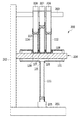
図1は、従来技術によるスライド式切換弁の一例として四方弁100を使用した空気調和機1を示す構成図である。図1において、空気調和機1は、四方弁100と、パイロット弁10と、室内熱交換器20と、膨張弁30と、室外熱交換器40と、圧縮機50とを備える。   FIG. 1 is a configuration diagram showing an air conditioner 1 that uses a four-way valve 100 as an example of a sliding type switching valve according to the prior art. In FIG. 1, the air conditioner 1 includes a four-way valve 100, a pilot valve 10, an indoor heat exchanger 20, an expansion valve 30, an outdoor heat exchanger 40, and a compressor 50.

パイロット弁10は、電磁切換部11と、電磁切換部11に接続される高圧継手管12、低圧継手管14、及び、2つの切換継手管13、15と、電磁切換部11の内部の図示しないパイロットスライド弁を駆動する電磁コイル部16と、電磁コイル部16に通電するリード線17とを備える。   The pilot valve 10 includes an electromagnetic switching unit 11, a high-pressure joint pipe 12 connected to the electromagnetic switching unit 11, a low-pressure joint pipe 14, two switching joint pipes 13 and 15, and an inside of the electromagnetic switching unit 11 (not shown). The electromagnetic coil part 16 which drives a pilot slide valve, and the lead wire 17 which supplies with electricity to the electromagnetic coil part 16 are provided.

パイロット弁10の高圧継手管12は、後述する第1の継手111と接続され、低圧継手管14は、後述する第3の継手113と接続され、切換継手管13は、後述する第1の弁室121に接続され、切換継手管15は、後述する第3の弁室123に接続される。   The high pressure joint pipe 12 of the pilot valve 10 is connected to a first joint 111 described later, the low pressure joint pipe 14 is connected to a third joint 113 described later, and the switching joint pipe 13 is a first valve described later. The switching joint pipe 15 is connected to a chamber 121 and is connected to a third valve chamber 123 described later.

室内熱交換器20、膨張弁30、及び、室外熱交換器40は、この順序で接続され、室内熱交換器20は、後述する第2の継手112と接続され、室外熱交換器40は、後述する第4の継手114と接続される。室内熱交換器20と、室外熱交換器40は、上述の順序ではなく、室内と室外が反対になっていてもよい。圧縮機50の吸入口52は、後述する第3の継手113に接続され、圧縮機50の吐出口51は、後述する第1の継手111に接続される。   The indoor heat exchanger 20, the expansion valve 30, and the outdoor heat exchanger 40 are connected in this order, the indoor heat exchanger 20 is connected to a second joint 112 described later, and the outdoor heat exchanger 40 is It connects with the 4th coupling 114 mentioned later. The indoor heat exchanger 20 and the outdoor heat exchanger 40 are not in the above-described order, and the inside and the outside may be reversed. The suction port 52 of the compressor 50 is connected to a third joint 113 described later, and the discharge port 51 of the compressor 50 is connected to a first joint 111 described later.

図1において、四方弁100は、概略、円筒状の弁本体101、2つのピストン102、103、スライド弁104、弁座108及び4本の継手111、112、113及び114を備えている。円筒状の弁本体101は、長手方向の中心軸O−Oを有し、その両端部は蓋体106、107により閉じられており、内部空間内に2つのピストン102、103、スライド弁104及び弁座108が収容されている。2つのピストン102、103は、円筒状の弁本体101と同心状に配置され、スライド弁104を収容した連結体105により一体的に連結され、円筒状の弁本体101の内部空間を3つの弁室121、122及び123に分割している。   In FIG. 1, a four-way valve 100 includes a generally cylindrical valve body 101, two pistons 102 and 103, a slide valve 104, a valve seat 108 and four joints 111, 112, 113 and 114. The cylindrical valve body 101 has a central axis OO in the longitudinal direction, and both ends thereof are closed by lids 106 and 107, and two pistons 102 and 103, a slide valve 104, and A valve seat 108 is accommodated. The two pistons 102 and 103 are arranged concentrically with the cylindrical valve main body 101 and are integrally connected by a connecting body 105 that houses a slide valve 104, and the internal space of the cylindrical valve main body 101 is divided into three valves. It is divided into chambers 121, 122 and 123.

ここで、第1の弁室121及び第3の弁室123は、それぞれに接続される切換継手管13及び切換継手管15を通じて、パイロット弁10を介していずれか一方の弁室が吸入パイプとしての第3の継手113内に連通するように構成されている。第2の弁室122は、吐出パイプとしての第1の継手111に連結されている。   Here, the first valve chamber 121 and the third valve chamber 123 are connected to the switching joint pipe 13 and the switching joint pipe 15, respectively, and one of the valve chambers serves as a suction pipe via the pilot valve 10. The third joint 113 is configured to communicate with the third joint 113. The second valve chamber 122 is connected to a first joint 111 serving as a discharge pipe.

2つのピストン102及び103とスライド弁104は、左右方向に一体的に移動するように構成されている。スライド弁104は、下方に向って開放する流路124を備え、弁座108の平坦面108a上を左右方向に移動する。弁座108には、3つの開口126、127及び128が設けられ、それぞれ、第2、第3、第4の継手112、113及び114に接続されている。したがって、スライド弁104の流路124は、弁座108の3つの開口126、127及び128のうちの2つを連通できるように形成されている。スライド弁104の流路124は、左右に移動することにより、開口126と127を、または開口127と128を連通させ、それにより冷媒の流路を切り換えている。例えば、図1に示すようにスライド弁104の流路124を介して開口126と127が連通しているとき、連通されない残りの開口128は、第2の弁室122に連通する。   The two pistons 102 and 103 and the slide valve 104 are configured to move integrally in the left-right direction. The slide valve 104 includes a flow path 124 that opens downward, and moves on the flat surface 108a of the valve seat 108 in the left-right direction. The valve seat 108 is provided with three openings 126, 127, and 128, which are connected to the second, third, and fourth joints 112, 113, and 114, respectively. Therefore, the flow path 124 of the slide valve 104 is formed so that two of the three openings 126, 127, and 128 of the valve seat 108 can communicate with each other. The flow path 124 of the slide valve 104 moves left and right to connect the openings 126 and 127 or the openings 127 and 128, thereby switching the refrigerant flow path. For example, as shown in FIG. 1, when the openings 126 and 127 communicate with each other via the flow path 124 of the slide valve 104, the remaining openings 128 that are not communicated communicate with the second valve chamber 122.

4本の継手のうち、第1の継手111は、D継手と呼ばれ、圧縮機50の吐出口51に連結される吐出パイプとしての継手であって、弁座108に対向する位置に設けられたDポート(主弁高圧ポート)と呼ばれる開口125に連結され、第2の弁室122に連通する。第3の継手113は、S継手と呼ばれ、圧縮機50の吸入口52に連結される吸入パイプとしての継手であって、弁座108の真ん中に設けられたSポート(主弁低圧ポート)と呼ばれる開口127に連結される。第2の継手112及び第4の継手114は、E継手及びC継手と呼ばれ、室内熱交換器20、膨張弁30、室外熱交換器40を介してお互いに接続される接続パイプとしての継手であって、それぞれ弁座108の左側及び右側に設けられたEポート及びCポート(主弁切換ポート)と呼ばれる開口126及び開口128に連結される。   Of the four joints, the first joint 111 is called a D joint and is a joint as a discharge pipe connected to the discharge port 51 of the compressor 50, and is provided at a position facing the valve seat 108. It is connected to an opening 125 called a D port (main valve high pressure port) and communicates with the second valve chamber 122. The third joint 113 is called an S joint and is a joint as a suction pipe connected to the suction port 52 of the compressor 50, and an S port (main valve low pressure port) provided in the middle of the valve seat 108. It is connected to the opening 127 called. The second joint 112 and the fourth joint 114 are called an E joint and a C joint, and are joints as connection pipes that are connected to each other via the indoor heat exchanger 20, the expansion valve 30, and the outdoor heat exchanger 40. In addition, they are connected to an opening 126 and an opening 128 called an E port and a C port (main valve switching port) provided on the left and right sides of the valve seat 108, respectively.

パイロット弁10は、電磁コイル部16にリード線17から通電し、あるいは、通電を遮断することにより駆動される。これにより、パイロット弁10の高圧継手管12から切換継手管13又は15を通り第1の弁室121又は第3の弁室123に高圧冷媒が供給され、四方弁100の切換が制御される。四方弁100は、第1の弁室121が低圧側である第3の継手113に連通している場合、圧縮機50→室外熱交換器40→膨張弁30→室内熱交換器20→圧縮機50とする冷房運転のための流路を形成する。逆に、第3の弁室123が低圧側である第3の継手113に連通している場合、四方弁100は、圧縮機50→室内熱交換器20→膨張弁30→室外熱交換器40→圧縮機50とする暖房運転のための流路を形成する。   The pilot valve 10 is driven by energizing the electromagnetic coil section 16 from the lead wire 17 or by cutting off the energization. As a result, the high-pressure refrigerant is supplied from the high-pressure joint pipe 12 of the pilot valve 10 to the first valve chamber 121 or the third valve chamber 123 through the switching joint pipe 13 or 15, and the switching of the four-way valve 100 is controlled. When the first valve chamber 121 is in communication with the third joint 113 on the low pressure side, the four-way valve 100 is connected to the compressor 50 → the outdoor heat exchanger 40 → the expansion valve 30 → the indoor heat exchanger 20 → the compressor. A flow path for cooling operation of 50 is formed. On the other hand, when the third valve chamber 123 communicates with the third joint 113 on the low pressure side, the four-way valve 100 includes the compressor 50 → the indoor heat exchanger 20 → the expansion valve 30 → the outdoor heat exchanger 40. → A flow path for heating operation as the compressor 50 is formed.

特開昭54−43324号公報JP 54-43324 A 中国実案公開第201391635号明細書Specification of China published No. 201391635

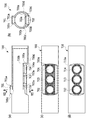
従来技術による四方弁100では、弁本体101と、弁座108と、4本の継手111、112、113、及び、114を接続するためには、例えば、図2に示されるようなろう付け冶具200を用いる。ろう付け冶具200は、水平な架台201、架台201上に垂直に延在する支柱202、架台201に平行であって水平に延在し、3つの押さえ棒を垂直に支持する上腕203、架台201に平行であって水平に延在する弁座受け204および継手管受け205を備えている。   In the four-way valve 100 according to the prior art, in order to connect the valve body 101, the valve seat 108, and the four joints 111, 112, 113, and 114, for example, a brazing jig as shown in FIG. 200 is used. The brazing jig 200 includes a horizontal base 201, a support column 202 that extends vertically on the base 201, an upper arm 203 that is parallel to the base 201 and extends horizontally, and supports three pressing bars vertically, and the base 201. The valve seat receiver 204 and the joint pipe receiver 205 extend in parallel with each other and horizontally.

四方弁100は、図2に示されるように、各部材がろう付け冶具200に仮組みされ、その後、ろう付けされる。各部材の仮組みは、具体的には、弁座108を弁座受け204に載せ、図1に示す状態から180°上下に逆転した状態で、弁本体101を弁座108が載っている弁座受け204に挿入する。次に、第1の継手111の一端を継手管受け205に嵌合するとともに、第1の継手111の他端を弁本体101の開口125に嵌め込み、第1の継手111を組み付ける。続いて、第2、第3、第4の継手112、113および114それぞれの一端を、弁座108に設けられた対応する開口126、127、128にそれぞれ嵌合し、他端に対応する押さえ棒206、207、208を挿入することでろう付け冶具200への仮組みが完了する。その後、ろう付けが行われる。   As shown in FIG. 2, each member of the four-way valve 100 is temporarily assembled in a brazing jig 200 and then brazed. Specifically, the temporary assembly of each member is a valve in which the valve seat 108 is mounted on the valve seat receiver 204 and the valve body 101 is mounted on the valve body 101 in a state where the valve seat is reversed 180 degrees up and down from the state shown in FIG. Insert into seat 204. Next, one end of the first joint 111 is fitted into the joint pipe receiver 205, and the other end of the first joint 111 is fitted into the opening 125 of the valve body 101 to assemble the first joint 111. Subsequently, one end of each of the second, third, and fourth joints 112, 113, and 114 is fitted into the corresponding opening 126, 127, 128 provided in the valve seat 108, and the presser corresponding to the other end The temporary assembly to the brazing jig 200 is completed by inserting the bars 206, 207, and 208. Thereafter, brazing is performed.

このように、従来の四方弁100においては、別々に形成された円筒状の弁本体101、弁座108および4本の継手111乃至114の全てを同時にろう付けするため、ろう付け箇所が多く、したがって、接合面積も大きくなるため難易度が高いろう付けとなる。また、円筒状の弁本体101と弁座108が別体であるため、3本の継手112乃至114が嵌め込まれる、円筒状の弁本体101に設けられた3つの挿入孔および該挿入孔それぞれに対応し、弁座108に形成される開口126、127、128それぞれの加工に精度が要求される。さらに、円筒形状の弁本体101と弁座108が別体であるため、ろう付け時における円筒形状の弁本体101の挿入孔と対応する弁座108の開口126乃至128との位置合わせにも時間を要する。そのため位置合わせを容易にするとともに、別部品である弁座108を保持するためにろう付け治具200は複雑な構造となる。その結果、治具の熱容量も大きくなり、大量の熱量を治具にとられてしまうため、仮組みに時間を要するだけでなくろう付けの時間も長くなっていた。特に弁座108は、体積が大きいだけでなく弁座受け204に直接接しているため温度が上がり難い。一方で、継手は薄肉の銅パイプであり温度が上がり易いため、ろう材は継手側に引かれてしまい弁座108の接合部に行き渡り難い。その結果、弁座108の接合部に隙間ができる、穴が開く等により気密性を保持できないという問題を生じていた。又、十分にろう材が弁本体接合部に行き渡ったとしても、弁本体101と弁座108が別体である為、ろう材がピストン摺動部まで流れてしまうという問題も生じていた。さらに、円筒状の弁本体101に管状の継手をろう付けする場合、ろう材が本体側面に流れ易くなり(ろうダレ)、接合部のろう材不足やろう材を浪費する恐れを生じていた。   As described above, in the conventional four-way valve 100, the cylindrical valve body 101, the valve seat 108 and the four joints 111 to 114 formed separately are brazed at the same time. Therefore, since the joining area becomes large, brazing is difficult. Further, since the cylindrical valve body 101 and the valve seat 108 are separate bodies, three insertion holes provided in the cylindrical valve body 101 into which the three joints 112 to 114 are fitted, and the insertion holes, respectively. Correspondingly, each of the openings 126, 127 and 128 formed in the valve seat 108 is required to be processed with accuracy. Furthermore, since the cylindrical valve body 101 and the valve seat 108 are separate, it takes time to align the insertion holes of the cylindrical valve body 101 and the corresponding openings 126 to 128 of the valve seat 108 during brazing. Cost. Therefore, the brazing jig 200 has a complicated structure in order to facilitate alignment and hold the valve seat 108 which is a separate part. As a result, the heat capacity of the jig is increased, and a large amount of heat is taken by the jig, so that not only the temporary assembly takes time but also the brazing time becomes long. In particular, the valve seat 108 not only has a large volume but also is in direct contact with the valve seat receiver 204, so that the temperature is difficult to rise. On the other hand, since the joint is a thin copper pipe and the temperature is likely to rise, the brazing material is pulled to the joint side and is difficult to reach the joint of the valve seat 108. As a result, there has been a problem that airtightness cannot be maintained due to a gap formed at the joint of the valve seat 108 or a hole being opened. Further, even if the brazing material has sufficiently spread to the valve main body joint portion, since the valve main body 101 and the valve seat 108 are separate, there has been a problem that the brazing material flows to the piston sliding portion. Further, when a tubular joint is brazed to the cylindrical valve body 101, the brazing material easily flows to the side surface of the main body (brazing), and there is a possibility that the brazing material is insufficient at the joint portion or the brazing material is wasted.

この課題を解決する手段として、特許文献1、2に示すような、弁本体と弁座をプレス加工により一体形状とする方法があった。しかしながら、特許文献1、2に示すような従来技術では、弁本体である薄肉パイプをプレス加工して弁座を形成するため、以下のような問題点があった。   As means for solving this problem, there has been a method in which the valve body and the valve seat are integrally formed by press working, as shown in Patent Documents 1 and 2. However, the conventional techniques as shown in Patent Documents 1 and 2 have the following problems because the valve seat is formed by pressing a thin pipe that is a valve body.

まず、特許文献1に示す発明では、薄肉パイプ状の弁本体を加工して弁座を形成するため、継手のろう付け代はパイプの板厚分程度しか確保することができないという問題点がある。この問題点に対しては、特許文献2に示す発明のように、バーリング加工等により、ろう付け部を立ち上げることにより対処することも考えられる。しかしバーリング加工する際は、バーリング穴に対して対面に穴がないと矢が入らないため加工が難しい。仮に加工できたとしても近接する弁ポートを離す必要があり、本体の大型化につながる。さらに、バーリング加工では、段差を設けることが難しく、継手の差し込み深さを一定位置に決定することが困難となる。   First, in the invention shown in Patent Document 1, since a valve body having a thin pipe shape is processed to form a valve seat, there is a problem in that the brazing allowance of the joint can ensure only about the plate thickness of the pipe. . It is conceivable to deal with this problem by raising a brazing part by burring or the like as in the invention shown in Patent Document 2. However, when burring, it is difficult to process because an arrow does not enter unless there is a hole facing the burring hole. Even if it can be processed, it is necessary to separate the adjacent valve ports, leading to an increase in the size of the main body. Furthermore, in burring, it is difficult to provide a step, and it is difficult to determine the joint insertion depth at a fixed position.

また、特許文献1及び2に示す発明では、弁本体である薄肉パイプに弁座を形成するため、近接するピストン摺動面が歪み易く真円に保つことが困難となり、作動不良となる可能性がある。   Further, in the inventions shown in Patent Documents 1 and 2, since the valve seat is formed on the thin pipe that is the valve body, the adjacent piston sliding surface is easily distorted and it is difficult to maintain a perfect circle, which may cause malfunction. There is.

また、図3に示すように、プレス加工により弁本体と弁座を形成した場合には、製造時に行われるふたカシメ工程において、カシメ治具302を使用して、弁本体301の両側に2つのふた106、107をカシメる際に、弁本体301が薄肉のパイプであるため強度不足となり、図3の点線部分303に示す、弁座のシール面301aが歪むおそれがある。その結果、スライド弁104と弁座部でシールすることができなくなり、高温冷媒が低温冷媒側へ漏れ、作動不良やシステム効率が低下するという問題点がある。   Further, as shown in FIG. 3, when the valve body and the valve seat are formed by press working, two crimping jigs 302 are used on both sides of the valve body 301 in the lid crimping process performed at the time of manufacture. When the lids 106 and 107 are caulked, the valve body 301 is a thin pipe, so that the strength is insufficient, and the sealing surface 301a of the valve seat shown by the dotted line portion 303 in FIG. 3 may be distorted. As a result, there is a problem that sealing cannot be performed between the slide valve 104 and the valve seat, and high-temperature refrigerant leaks to the low-temperature refrigerant side, resulting in poor operation and system efficiency.

また、図4に示すように、プレス加工により弁本体と弁座を形成した場合には、薄肉の弁座部に継手が直接ろう付けされているため、空気調和機として組み込む際、システム配管401、402、403が接続されると、例えば、システム配管401、402、403のそれぞれに、図4の矢印で示した方向に外力が加わると図4の点線部分404に示す、弁座のシール面301aが歪むおそれがあり、前記と同様の問題点がある。   Further, as shown in FIG. 4, when the valve body and the valve seat are formed by pressing, the joint is directly brazed to the thin valve seat portion. , 402, 403, for example, when an external force is applied to each of the system piping 401, 402, 403 in the direction indicated by the arrow in FIG. 4, the seal surface of the valve seat shown in the dotted line portion 404 in FIG. 301a may be distorted, and there are the same problems as described above.

従って、本発明の目的は、ろう付けの問題点を解消し、従来技術のプレス加工による弁本体の強度不足による問題点も解消できるスライド式切換弁の弁本体、スライド式切換弁、及び、空気調和機を提供することである。   Accordingly, an object of the present invention is to eliminate the problem of brazing and solve the problem due to insufficient strength of the valve body by press working of the prior art, the valve body of the slide type switching valve, the sliding type switching valve, and the air It is to provide a harmony machine.

上記課題を解決するために、本発明のスライド式切換弁の弁本体は、略円筒形状であって、少なくとも1つの継手が連結される弁座と、上記少なくとも1つの継手とは別の継手がさらに上記弁本体の上記弁座とは別の位置に直接連結される突起部とを備え、上記弁座は、上記弁本体の内部に平坦面を有し、上記弁本体には、上記弁座の上記弁本体の内部の平坦面が上記弁本体の円筒形状の内周面と接する部分の上記円筒形状が内側に窪むことにより形成される熱受渡部がさらに設けられ、上記弁本体と、上記弁座とは、鍛造により一体的に形成されることを特徴とする。 In order to solve the above problems, a valve body of a slide type switching valve according to the present invention has a substantially cylindrical shape, a valve seat to which at least one joint is connected, and a joint different from the at least one joint. And a protrusion connected directly to a position different from the valve seat of the valve body, the valve seat having a flat surface inside the valve body, and the valve body includes the valve seat. A heat transfer part formed by the cylindrical shape of the portion of the valve body in contact with the cylindrical inner peripheral surface of the valve body being recessed inward, the valve body; and The valve seat is integrally formed by forging.

また、上記弁本体には、上記円筒形状の外周部のうち、上記少なくとも1つの継手が連結される部分の周囲に梁が設けられるものとしてもよい。   The valve body may be provided with a beam around a portion of the cylindrical outer peripheral portion to which the at least one joint is connected.

また、上記弁本体には、上記少なくとも1つの継手及び上記別の継手が連結される部分に開口が設けられ、開口内部に段差が形成されるものとしてもよい。   The valve body may be provided with an opening at a portion where the at least one joint and the another joint are connected, and a step is formed inside the opening.

また、上記弁本体には、上記突起部とは別の位置に、パイロット弁が連結される別の突起部をさらに備えるものとしてもよい。   The valve main body may further include another protrusion to which the pilot valve is connected at a position different from the protrusion.

上記課題を解決するために、本発明のスライド式切換弁の弁本体の鍛造品は、スライド式切換弁の弁本体を形成しており、上記鍛造品は、略円筒形状であり、上記円筒形状の一部に弁座に対応する肉厚部と、上記円筒形状の内部空間を分割する仕切り壁と、上記円筒形状の外周部の上記肉厚部以外の位置に少なくとも1つの突起部とを有することを特徴とする。   In order to solve the above problems, the forged product of the valve body of the slide type switching valve of the present invention forms the valve body of the sliding type switching valve, and the forged product has a substantially cylindrical shape, and the cylindrical shape A thick wall portion corresponding to the valve seat, a partition wall that divides the cylindrical internal space, and at least one protrusion at a position other than the thick wall portion of the cylindrical outer peripheral portion. It is characterized by that.

上記課題を解決するために、本発明のスライド式切換弁は、上記弁本体と、上記弁座の上記弁本体の内部の平坦面上を移動し、上記弁本体に直接連結される上記別の継手と上記弁座を介して連結される上記少なくとも1つの継手とを連通させるスライド弁とを備えることを特徴とする。
In order to solve the above-mentioned problem, the slide type switching valve according to the present invention moves on the flat surface inside the valve body of the valve body and the valve body of the valve seat and is connected to the valve body directly. And a slide valve for communicating the joint with the at least one joint coupled via the valve seat.

上記課題を解決するために、本発明の空気調和機は、上記スライド式切換弁を使用することを特徴とする。   In order to solve the above-described problems, an air conditioner according to the present invention uses the above-mentioned slide type switching valve.

本発明のスライド式切換弁の弁本体、スライド式切換弁、及び、空気調和機によれば、弁本体と弁座を鍛造により一体形成することにより、ろう付けの問題点を解消でき、厚肉部及び窪み部を形成できるため、従来技術で懸念される強度不足を解消できる。   According to the valve main body, the slide type switching valve, and the air conditioner of the present invention, the problem of brazing can be eliminated by integrally forming the valve main body and the valve seat by forging. Since a part and a hollow part can be formed, the lack of strength which is a concern in the prior art can be resolved.

また、本発明のスライド式切換弁によれば、弁本体と弁座を鍛造により一体形成することにより、熱受渡部の体積を小さくし、熱ロスを抑えることができるため、空気調和機のシステム効率を向上させることができる。   In addition, according to the slide type switching valve of the present invention, the valve body and the valve seat are integrally formed by forging, thereby reducing the volume of the heat transfer section and suppressing heat loss. Efficiency can be improved.

従来技術によるスライド式切換弁の一例としてパイロット式の冷媒流路切換用四方弁を使用した空気調和機を示す構成図である。It is a block diagram which shows the air conditioner which uses the pilot-type four-way valve for refrigerant | coolant flow path switching as an example of the slide type switching valve by a prior art. 従来技術によるスライド式切換弁の弁本体と弁座と継手をろう付けするために、ろう付け治具へ仮組みしている状態を示す図である。It is a figure which shows the state temporarily assembled to the brazing jig | tool in order to braze the valve main body of the slide type switching valve by a prior art, a valve seat, and a coupling. 従来技術によるプレス加工により形成された四方弁のふたカシメ工程を示す図である。It is a figure which shows the lid crimping process of the four-way valve formed by the press work by a prior art. 従来技術によるプレス加工により形成された四方弁と、システム配管を接続し外力が加わった状態を示す図である。It is a figure which shows the state which connected the four-way valve formed by the press work by a prior art, and system piping and applied external force. 本発明の第1の実施形態のスライド式切換弁である四方弁の弁本体を形成するための鍛造品を示す図であり、図5(a)は、断面図であり、図5(b)は、図5(a)に示すVB−VB断面図であり、図5(c)は、図5(b)に示すVC部分の拡大図である。It is a figure which shows the forged product for forming the valve main body of the four-way valve which is a slide type switching valve of the 1st Embodiment of this invention, Fig.5 (a) is sectional drawing, FIG.5 (b) These are VB-VB sectional views shown in Drawing 5 (a), and Drawing 5 (c) is an enlarged view of the VC section shown in Drawing 5 (b). 図5に示す弁本体の鍛造品を形成するための金型の構成図である。It is a block diagram of the metal mold | die for forming the forged product of the valve main body shown in FIG. 図5に示す弁本体の鍛造品を加工して形成された本発明の第1の実施形態のスライド式切換弁の弁本体を示す図であり、図7(a)は、弁本体の部分断面図であり、図7(b)は、図7(a)に示すVIIB−VIIB断面図であり、図7(c)は、図7(a)に示す弁本体の底面図であり、図7(d)は、図7(c)とは別の弁本体の例を示す底面図である。It is a figure which shows the valve main body of the slide type switching valve of the 1st Embodiment of this invention formed by processing the forged goods of the valve main body shown in FIG. 5, (a) is a partial cross section of a valve main body. 7 (b) is a sectional view taken along the line VIIB-VIIB shown in FIG. 7 (a), and FIG. 7 (c) is a bottom view of the valve body shown in FIG. 7 (a). (D) is a bottom view showing an example of a valve body different from FIG. 7 (c). 本発明の効果を説明する図であって、従来技術による四方弁の構造を示す図であり、図8(a)は、従来技術による四方弁の断面図であり、図8(b)は、図8(a)に示すVIIIB−VIIIB断面図であり、図8(c)は、図8(b)に示すVIIIC部分の拡大図である。It is a figure explaining the effect of the present invention, it is a figure showing the structure of a four-way valve according to the prior art, FIG. 8 (a) is a sectional view of the four-way valve according to the prior art, FIG. 8 (b), It is VIIIB-VIIIB sectional drawing shown to Fig.8 (a), FIG.8 (c) is an enlarged view of the VIIIC part shown to FIG.8 (b). 本発明の効果を説明する図であって、本発明の第1の実施形態のスライド式切換弁である四方弁の構造を示す図であり、図9(a)は、本発明の第1の実施形態のスライド式切換弁である四方弁の断面図であり、図9(b)は、図9(a)に示すIXB−IXB断面図であり、図9(c)は、図9(b)に示すIXC部分の拡大図である。It is a figure explaining the effect of this invention, Comprising: It is a figure which shows the structure of the four-way valve which is a slide type switching valve of the 1st Embodiment of this invention, Fig.9 (a) is the 1st of this invention It is sectional drawing of the four-way valve which is a slide type switching valve of embodiment, FIG.9 (b) is IXB-IXB sectional drawing shown to Fig.9 (a), FIG.9 (c) is FIG.9 (b). It is an enlarged view of the IXC portion shown in FIG. 本発明の第2の実施形態のスライド式切換弁であるパイロット弁を弁本体に直接取り付けた四方弁に用いる弁本体の鍛造品を示す図であり、図10(a)は、正面図であり、図10(b)は、右側面図である。It is a figure which shows the forged product of the valve main body used for the four-way valve which attached the pilot valve which is the slide type switching valve of the 2nd Embodiment of this invention directly to the valve main body, and Fig.10 (a) is a front view. FIG. 10B is a right side view. 本発明の第2の実施形態のスライド式切換弁であるパイロット弁を弁本体に直接取り付けた四方弁を示す図であり、図11(a)は、正面図であり、図11(b)は、右側面図である。It is a figure which shows the four-way valve which attached the pilot valve which is a slide type switching valve of the 2nd Embodiment of this invention directly to the valve main body, Fig.11 (a) is a front view, FIG.11 (b) is FIG. FIG. 図11に示す四方弁の弁本体とパイロット弁との接続部分を示す拡大図である。It is an enlarged view which shows the connection part of the valve main body and pilot valve of the four-way valve shown in FIG. 本発明の効果を説明する図であって、図13(a)は、従来技術のプレス加工により形成された弁本体と電磁切換部との接続部分を示す部分断面図であり、図13(b)は、本発明の第2の実施形態のスライド式切換弁の鍛造により形成された弁本体と電磁切換部との接続部分を示す部分断面図である。FIG. 13 (a) is a partial cross-sectional view illustrating a connection portion between a valve body and an electromagnetic switching portion formed by press processing according to the prior art. ) Is a partial cross-sectional view showing a connection portion between a valve main body and an electromagnetic switching portion formed by forging a sliding switching valve according to a second embodiment of the present invention.

以下、本発明の実施形態を、図面を参照して説明する。   Embodiments of the present invention will be described below with reference to the drawings.

まず、第1の実施形態について説明する。   First, the first embodiment will be described.

尚、以下の説明における上下左右方向の概念は、添付の図面における上下左右に対応しており、各部材の相対的な位置関係を示すものであって、絶対的な位置関係を示すものではない。   Note that the concept of the vertical and horizontal directions in the following description corresponds to the vertical and horizontal directions in the accompanying drawings, and indicates the relative positional relationship of each member, and does not indicate the absolute positional relationship. .

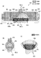
図5は、本発明の第1の実施形態のスライド式切換弁である四方弁の弁本体を形成するための鍛造品500を示す図であり、図5(a)は、断面図であり、図5(b)は、図5(a)に示すVB−VB断面図であり、図5(c)は、図5(b)に示すVC部分の拡大図であり、図6は、図5に示す弁本体の鍛造品500を形成するための金型の構成図である。   FIG. 5 is a view showing a forged product 500 for forming a valve body of a four-way valve that is a sliding type switching valve according to the first embodiment of the present invention, and FIG. 5 (a) is a sectional view. 5B is a VB-VB cross-sectional view shown in FIG. 5A, FIG. 5C is an enlarged view of the VC portion shown in FIG. 5B, and FIG. It is a block diagram of the metal mold | die for forming the forged product 500 of the valve main body shown in FIG.

図5において、弁本体の鍛造品500は、厚肉部500aや窪み部500dを形成できるため、従来技術によるプレス加工により形成された弁本体を使用するスライド式切換弁で懸念される強度不足等を解消できる。   In FIG. 5, the valve body forged product 500 can form the thick part 500a and the hollow part 500d, so that the strength of the slide type switching valve using the valve body formed by press working according to the prior art is insufficient. Can be eliminated.

図5(a)に示す、弁本体の鍛造品500は、概略円筒形状を有しており、円筒内部の中央下部には、後述する弁座700aに対応する肉厚部500aが形成される。また、円筒内部の肉厚部500aの端部には、仕切り壁500bが形成されている。   A forged product 500 of the valve body shown in FIG. 5A has a substantially cylindrical shape, and a thick portion 500a corresponding to a valve seat 700a described later is formed in a central lower portion inside the cylinder. Moreover, the partition wall 500b is formed in the edge part of the thick part 500a inside a cylinder.

例えば、図6に示すように、弁本体の鍛造品500は、円筒形状の外部の形状を形成する一対の第1の鍛造金型601と、円筒形状の内部の形状を左右から形成する一対の第2の鍛造金型602とにより形成される。第1の鍛造金型601は、図6に示すように上下に分割されても、それ以外の方向に分割されても構わない。また、円筒形状の内部形状をした第2の鍛造金型602が、左右から打ち付けられるため、円筒内部に軸線方向に垂直に延在する仕切り壁500bが形成される。仕切り壁500bの位置も上述のような肉厚部500aの端部に限定されない。また、仕切り壁は垂直ではなく、斜め方向に延在していてもよく、内部空間を分割できる構造であればよい。   For example, as shown in FIG. 6, the forged product 500 of the valve body includes a pair of first forging dies 601 that form a cylindrical outer shape and a pair of cylindrical inner shapes that are formed from the left and right. The second forging die 602 is formed. The first forging die 601 may be divided vertically as shown in FIG. 6 or may be divided in other directions. In addition, since the second forging die 602 having a cylindrical internal shape is driven from the left and right, a partition wall 500b extending perpendicularly to the axial direction is formed inside the cylinder. The position of the partition wall 500b is not limited to the end of the thick part 500a as described above. Further, the partition wall is not vertical, but may extend in an oblique direction, as long as the internal space can be divided.

図5(a)に示すように、弁本体の鍛造品500の肉厚部500aに対向する位置であって、図5(a)に示す中央のやや左側の位置には、後述するD継手811が接続される開口701が設けられる円柱形状の突起部500cが設けられる。後述するように、突起部500cが設けられることにより、D継手811が接続される開口部に段差が設けられるとともに、接続部分の強度が保たれる。なお、ここでは、突起部500cは、肉厚部500aに対向し、中央やや左側に設けられるものとしたが、これには限定されない。また、図5(c)に示すように、弁本体の鍛造品500には、肉厚部500aの円筒形状の内部の平坦面が円筒形状の内周面と接する部分の円筒形状の内周側又は外周側の少なくとも一方が内側に窪むことにより形成される窪み部500dが設けられる。後述するように、窪み部500dが設けられることにより、熱受渡部βの体積を小さくすることができ、熱ロスを抑えることができる。   As shown in FIG. 5 (a), at a position facing the thick portion 500a of the forged product 500 of the valve body and slightly on the left side of the center shown in FIG. A columnar projection 500c is provided in which an opening 701 to which is connected is provided. As will be described later, by providing the protrusion 500c, a step is provided in the opening to which the D joint 811 is connected, and the strength of the connection portion is maintained. Here, the protruding portion 500c is provided opposite to the thick portion 500a and provided at the center and slightly on the left side, but is not limited thereto. Further, as shown in FIG. 5C, the forged product 500 of the valve body includes a cylindrical inner peripheral side of a portion where the flat inner surface of the thick part 500a is in contact with the cylindrical inner peripheral surface. Alternatively, a recessed portion 500d formed by recessing at least one of the outer peripheral side inward is provided. As will be described later, by providing the recessed portion 500d, the volume of the heat transfer section β can be reduced, and heat loss can be suppressed.

図7は、図5に示す弁本体の鍛造品500を加工して形成された本発明の第1の実施形態のスライド式切換弁の弁本体700を示す図であり、図7(a)は、弁本体700の部分断面図であり、図7(b)は、図7(a)に示すVIIB−VIIB断面図であり、図7(c)は、図7(a)に示す弁本体700の底面図であり、図7(d)は、図7(c)とは別の弁本体710を示す底面図である。   FIG. 7 is a view showing a valve body 700 of the sliding switching valve according to the first embodiment of the present invention formed by processing the forged product 500 of the valve body shown in FIG. 7B is a partial cross-sectional view of the valve body 700, FIG. 7B is a cross-sectional view of VIIB-VIIB shown in FIG. 7A, and FIG. 7C is a valve main body 700 shown in FIG. 7A. FIG. 7D is a bottom view showing a valve main body 710 different from FIG. 7C.

図7(a)、(b)、(c)に示す本発明のスライド式切換弁の弁本体700は、図5に示す弁本体の鍛造品500を切削加工し、仕切り壁500bを取り除き、突起部500c、及び、肉厚部500aに開口701、702、703、及び、704を設けることにより形成される。ここでは、弁本体700は、切削加工により形成されたが、その他の加工方法で形成されても構わない。   7 (a), 7 (b), and 7 (c), the valve body 700 of the slide type switching valve of the present invention is formed by cutting the valve body forged product 500 shown in FIG. It is formed by providing openings 701, 702, 703, and 704 in the portion 500c and the thick portion 500a. Here, the valve body 700 is formed by cutting, but may be formed by other processing methods.

弁本体700には、弁座700aが設けられる。弁座700aには、後述するESC継手812、813、814が連結される開口702、703、704が形成される。開口702、703、704のそれぞれには、切削加工により継手の位置出し用として使用される段差702a、703a、704aが設けられる。このように、切削加工により段差702a、703a、704aを形成することにより、継手の挿入深さを容易に決定できるとともに、ろう付け代を確保でき、安定したろう付けを行うことができる。   The valve body 700 is provided with a valve seat 700a. In the valve seat 700a, openings 702, 703, and 704 to which ESC joints 812, 813, and 814, which will be described later, are connected are formed. Each of the openings 702, 703, and 704 is provided with steps 702a, 703a, and 704a used for positioning the joint by cutting. Thus, by forming the steps 702a, 703a, and 704a by cutting, the insertion depth of the joint can be easily determined, the brazing allowance can be secured, and stable brazing can be performed.

弁本体700の弁座700aの対向する位置には、円筒形状の突起部500cを加工して形成された継手連結部700cが設けられる。継手連結部700cには、後述するD継手811が連結される開口701が形成される。開口701には、切削加工により継手の位置出しとして使用される段差701aが設けられ、段差702a乃至704aと同様の効果が得られる。   A joint coupling portion 700c formed by machining a cylindrical projection 500c is provided at a position facing the valve seat 700a of the valve body 700. An opening 701 to which a D joint 811 described later is connected is formed in the joint connecting portion 700c. The opening 701 is provided with a step 701a used for positioning the joint by cutting, and the same effect as the steps 702a to 704a can be obtained.

弁本体700の窪み部500dに対応する位置には、弁座700aの弁本体内部の平坦面700bが弁本体700の円筒形状の内周面と接する部分の円筒形状が、内側に窪むことにより形成される窪み部700dが設けられ、それにより熱受渡部βの体積を小さくすることができ、熱ロスを抑えることができる。   At a position corresponding to the recessed portion 500d of the valve body 700, the cylindrical shape of the portion where the flat surface 700b inside the valve body of the valve seat 700a contacts the cylindrical inner peripheral surface of the valve body 700 is recessed inward. The formed hollow portion 700d is provided, whereby the volume of the heat transfer portion β can be reduced, and heat loss can be suppressed.

また、図7(c)に示すように、弁本体700の弁座700aが形成される部分の円筒形状の外周部には、開口702、703、704の周囲に、端面が直線の梁700eが設けられる。梁700eは、ここでは、鍛造加工により形成されるが、円筒形状の弁本体の鍛造品から切削により形成してもよい。弁本体700に梁700eが設けられることにより、例えば、蓋カシメ工程時に弁座部分が歪むことを防止できる等、弁本体700の外力に対する強度を確保することができる。   Further, as shown in FIG. 7C, a beam 700e having a straight end surface is formed around the openings 702, 703, and 704 on the cylindrical outer peripheral portion of the valve body 700 where the valve seat 700a is formed. Provided. Here, the beam 700e is formed by forging, but may be formed by cutting a forged product of a cylindrical valve body. By providing the beam 700e on the valve body 700, it is possible to ensure strength against the external force of the valve body 700, for example, preventing the valve seat portion from being distorted during the lid caulking process.

また、図7(d)に示す弁本体710のように、図7(c)に示す弁本体700の梁700eの形状と異なり、端面が開口712、713、714に合わせて曲線の梁710eが設けられるものとしてもよい。このような形状によっても、例えば、蓋カシメ工程時に弁座部分が歪むことを防止できる等、弁本体710の外力に対する強度を確保することができる。   7D, unlike the shape of the beam 700e of the valve body 700 shown in FIG. 7C, the curved beam 710e has end faces that match the openings 712, 713, and 714. It may be provided. Even with such a shape, for example, the strength against the external force of the valve body 710 can be ensured, for example, the valve seat portion can be prevented from being distorted during the lid crimping process.

図8は、本発明の効果を説明する図であって、従来技術による四方弁800の構造を示す図であり、図8(a)は、従来技術による四方弁800の断面図であり、図8(b)は、図8(a)に示すVIIIB−VIIIB断面図であり、図8(c)は、図8(b)に示すVIIIC部分の拡大図である。   FIG. 8 is a diagram illustrating the effect of the present invention, and is a diagram showing the structure of a four-way valve 800 according to the prior art. FIG. 8A is a cross-sectional view of the four-way valve 800 according to the prior art. 8 (b) is a cross-sectional view taken along the line VIIIB-VIIIB shown in FIG. 8 (a), and FIG. 8 (c) is an enlarged view of the VIIIC portion shown in FIG. 8 (b).

図8(a)において、従来技術による四方弁800は、円筒形状の弁本体801と、弁本体801を3つの弁室である第1の弁室821、第2の弁室822、及び、第3の弁室823に分割する2つのピストン802、803と、下方に向って開放する流路824を備えるスライド弁804と、2つのピストン802、803及びスライド弁804を一体的に連結する連結体805と、弁本体801の両端を閉じる蓋体806、807と、弁本体内部に平坦面808aを有する弁座808と、4本の継手811(D継手)、812、813、814(ESC継手)とを備える。詳細な説明は、図1に示す四方弁100と同様であるため省略する。   8A, a four-way valve 800 according to the prior art includes a cylindrical valve body 801, a first valve chamber 821, a second valve chamber 822, and three valve chambers 801, Two pistons 802 and 803 that are divided into three valve chambers 823, a slide valve 804 having a flow path 824 that opens downward, and a coupling body that integrally connects the two pistons 802 and 803 and the slide valve 804 805, lids 806 and 807 that close both ends of the valve body 801, a valve seat 808 having a flat surface 808a inside the valve body, and four joints 811 (D joint), 812, 813, and 814 (ESC joint) With. The detailed description is the same as that of the four-way valve 100 shown in FIG.

図8(a)に示すように、スライド弁804が弁座808の平坦面808aの右側に移動した状態となっており、高温冷媒は、図8(a)、図8(b)の濃いハッチングに示すように、第1の継手(D継手)811、第1の弁室821、第2の弁室822、及び、第2の継手(E継手)812を満たした状態になっている。反対に、低温冷媒は、図8(a)、図8(b)の薄いハッチングに示すように、第3の継手(S継手)813、流路824、第4の継手(C継手)814、及び、第3の弁室823を満たした状態になっている。   As shown in FIG. 8A, the slide valve 804 is moved to the right side of the flat surface 808a of the valve seat 808, and the high-temperature refrigerant is dark hatched in FIGS. 8A and 8B. As shown, the first joint (D joint) 811, the first valve chamber 821, the second valve chamber 822, and the second joint (E joint) 812 are satisfied. On the other hand, as shown in the thin hatching in FIGS. 8A and 8B, the low-temperature refrigerant is composed of a third joint (S joint) 813, a flow path 824, a fourth joint (C joint) 814, In addition, the third valve chamber 823 is filled.

従来技術による四方弁800は、弁本体801と、弁座808とがろう付けにより接続されているため、図8(a)、図8(c)に示すように、弁本体801から弁座808に伝達する熱受渡部αの体積が大きくなっている。このため、圧縮機50から吐出された高温冷媒の熱受渡部αに吸収される熱量が多く、その熱は低温冷媒側に逃げてしまい、システム効率のロスが発生していた。   In the conventional four-way valve 800, the valve main body 801 and the valve seat 808 are connected by brazing. Therefore, as shown in FIGS. 8A and 8C, the valve main body 801 and the valve seat 808 are connected. The volume of the heat transfer part α that is transmitted to is increased. Therefore, a large amount of heat is absorbed by the heat transfer section α of the high-temperature refrigerant discharged from the compressor 50, and the heat escapes to the low-temperature refrigerant side, resulting in a loss of system efficiency.

図9は、本発明の効果を説明する図であって、本発明の第1の実施形態のスライド式切換弁である四方弁900の構造を示す図であり、図9(a)は、本発明の第1の実施形態のスライド式切換弁である四方弁900の断面図であり、図9(b)は、図9(a)に示すIXB−IXB断面図であり、図9(c)は、図9(b)に示すIXC部分の拡大図である。   FIG. 9 is a diagram for explaining the effect of the present invention, and is a diagram showing the structure of a four-way valve 900 that is a slide type switching valve according to the first embodiment of the present invention. FIG. FIG. 9B is a cross-sectional view of the four-way valve 900 that is the sliding switching valve of the first embodiment of the invention, and FIG. 9B is a cross-sectional view taken along the line IXB-IXB shown in FIG. FIG. 10 is an enlarged view of the IXC portion shown in FIG.

図9に示す四方弁900は、弁本体として、図7に示す鍛造により形成された弁本体700あるいは710を使用しており、それ以外の構成は、図8に示す従来技術による四方弁800の構成と同じである。同様の構成には同じ符号を付し、ここでは説明を省略する。なお、ここでは弁本体700を使用したものとして説明する。   The four-way valve 900 shown in FIG. 9 uses the valve body 700 or 710 formed by forging shown in FIG. 7 as the valve body, and other configurations are the same as those of the conventional four-way valve 800 shown in FIG. Same as the configuration. Similar components are denoted by the same reference numerals, and description thereof is omitted here. Here, description will be made assuming that the valve body 700 is used.

図9(a)に示すように、図8と同様に、スライド弁804が弁座700aの平坦面700bの右側に移動した状態となっており、高温冷媒は、図9(a)、図9(b)の濃いハッチングに示すように、第1の継手(D継手)811、第1の弁室821、第2の弁室822、及び、第2の継手(E継手)812を満たした状態になっている。反対に、低温冷媒は、図9(a)、図9(b)の薄いハッチングに示すように、第3の継手(S継手)813、流路824、第4の継手(C継手)814、及び、第3の弁室823を満たした状態になっている。   As shown in FIG. 9A, as in FIG. 8, the slide valve 804 is moved to the right side of the flat surface 700b of the valve seat 700a, and the high-temperature refrigerant is shown in FIGS. (B) As shown in the dark hatching, the first joint (D joint) 811, the first valve chamber 821, the second valve chamber 822, and the second joint (E joint) 812 are satisfied. It has become. On the other hand, as shown in the thin hatching in FIG. 9A and FIG. 9B, the low-temperature refrigerant is a third joint (S joint) 813, a flow path 824, a fourth joint (C joint) 814, In addition, the third valve chamber 823 is filled.

本発明に係るスライド式切換弁としての四方弁900は、図7に示す弁本体700を使用しており、弁本体700と弁座700aは、鍛造により一体に形成することで、図8(c)に示す従来技術の弁本体とは異なり、窪み部700dを形成でき、図9(a)及び図9(c)に示すような体積が小さい熱受渡部βが形成できる。これにより、従来技術で問題となっていた圧縮機50から吐出された高温冷媒の熱が熱受渡部βから低温側に逃げることを抑制することができ、システム効率のロスを低減できる。なお、図8に示すような、弁本体801と弁座808を別々に形成し、ろう付けにより接続する構造では、熱受渡部αの体積を小さくすることは困難である。   The four-way valve 900 as a slide type switching valve according to the present invention uses the valve body 700 shown in FIG. 7, and the valve body 700 and the valve seat 700a are integrally formed by forging, so that FIG. Unlike the prior art valve main body shown in FIG. 9A, a hollow portion 700d can be formed, and a heat transfer portion β having a small volume as shown in FIGS. 9A and 9C can be formed. Thereby, it can suppress that the heat | fever of the high temperature refrigerant | coolant discharged from the compressor 50 which was a problem in the prior art escapes from the heat delivery part (beta) to the low temperature side, and can reduce the loss of system efficiency. In the structure in which the valve main body 801 and the valve seat 808 are separately formed and connected by brazing as shown in FIG. 8, it is difficult to reduce the volume of the heat transfer section α.

次に、第2の実施形態について説明する。   Next, a second embodiment will be described.

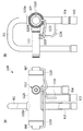
図10は、本発明の第2の実施形態のスライド式切換弁であるパイロット弁を弁本体に直接取り付けた四方弁に用いる弁本体の鍛造品1000を示す図であり、図10(a)は、正面図であり、図10(b)は、右側面図である。   FIG. 10 is a view showing a forged product 1000 of a valve body used in a four-way valve in which a pilot valve which is a sliding type switching valve according to a second embodiment of the present invention is directly attached to the valve body, and FIG. FIG. 10B is a right side view.

図10(a)、図10(b)において、後に切削加工などにより、弁本体1120を形成するための弁本体の鍛造品1000は、鍛造により形成される。鍛造品1000には、図5に示す弁本体の鍛造品500と同様に円筒内部の中央下部には、弁座(図示せず)に対応する肉厚部1000aと、円筒内部の肉厚部1000aの端部に形成される仕切り壁1000bと、円筒形状の外部に設けられ、D継手811が接続される継手連結部1120cに対応する円柱形状の突起部1000cと、窪み部1000dと、梁1000eが設けられる。さらに、鍛造品1000には、後述するパイロット弁1110が接続されるパイロット弁接続部1120fに対応する円柱形状の突起部1000fが鍛造品1000の正面中央右よりに設けられる。なお、パイロット弁接続部1120fに対応する突起部1000fは、後述するように、パイロット弁1110が弁本体1120内部の第2の弁室822に接続する必要があるため、弁本体1120の中央付近であって、継手連結部1120cに対応する突起部1000cと別の位置であれば、どこでも設けることができる。   10A and 10B, a forged product 1000 of the valve body for forming the valve body 1120 later by cutting or the like is formed by forging. In the forged product 1000, a thick portion 1000a corresponding to a valve seat (not shown) and a thick portion 1000a inside the cylinder are provided at the lower center of the inside of the cylinder as in the forged product 500 of the valve body shown in FIG. A partition wall 1000b formed at the end of the cylindrical portion, a cylindrical protrusion 1000c corresponding to a joint connecting portion 1120c to which the D joint 811 is connected, and a hollow portion 1000d, and a beam 1000e. Provided. Further, the forged product 1000 is provided with a cylindrical protrusion 1000f corresponding to a pilot valve connecting portion 1120f to which a pilot valve 1110 described later is connected from the front center right of the forged product 1000. Note that the protrusion 1000f corresponding to the pilot valve connection portion 1120f needs to be connected to the second valve chamber 822 inside the valve body 1120, as will be described later. Thus, it can be provided anywhere as long as it is in a position different from the protrusion 1000c corresponding to the joint connecting portion 1120c.

弁本体の鍛造品1000は、鍛造により形成されるため、部分的に突起部を設けることが可能であり、パイロット弁1110の接続箇所であるパイロット弁接続部1120fに対応する突起部1000fを弁本体に設けることが簡単にできる。プレス加工の場合でもバーリングをたてることにより突起部を設けることは可能であるが、バーリングの立ち上げ部を長く設けられないため、ろう付け代を確保しにくい。また、段差を設けることが難しく、継手の差し込み深さを決定することが困難である。さらに、寸法精度が出しにくいためクリアランスが安定しない。その結果ろう付けが不安定になりやすいという問題がある。また、バーリング加工する際、バーリング穴に対して対面に穴がないと矢が入らないため加工が難しいという位置の制約があり、例えば、図10に示す弁本体の鍛造品1000の突起部1000fのような最適な位置にバーリングをたてることが難しいという問題がある。   Since the forged product 1000 of the valve body is formed by forging, it is possible to provide a projection partly, and the projection part 1000f corresponding to the pilot valve connection part 1120f, which is a connection point of the pilot valve 1110, is provided on the valve body. Can be easily installed. Even in the case of press working, it is possible to provide the protrusions by raising the burring, but it is difficult to secure the brazing allowance because the rising part of the burring cannot be provided long. In addition, it is difficult to provide a step and it is difficult to determine the insertion depth of the joint. Furthermore, since the dimensional accuracy is difficult to obtain, the clearance is not stable. As a result, there is a problem that brazing tends to become unstable. Further, when performing burring, there is a restriction on the position that machining is difficult because an arrow does not enter unless there is a hole facing the burring hole. For example, the protrusion 1000f of the forged product 1000 of the valve body shown in FIG. There is a problem that it is difficult to burring at such an optimal position.

図11は、本発明の第2の実施形態のスライド式切換弁であるパイロット弁を弁本体に直接取り付けた四方弁1100を示す図であり、図11(a)は、正面図であり、図11(b)は、右側面図であり、図12は、図11に示す四方弁1100の弁本体1120とパイロット弁1110との接続部分を示す拡大図である。   FIG. 11 is a view showing a four-way valve 1100 in which a pilot valve, which is a slide type switching valve according to a second embodiment of the present invention, is directly attached to a valve body, and FIG. 11 (a) is a front view. 11 (b) is a right side view, and FIG. 12 is an enlarged view showing a connection portion between the valve main body 1120 and the pilot valve 1110 of the four-way valve 1100 shown in FIG.

図11(a)、図11(b)において、四方弁1100は、図10に示す弁本体の鍛造品1000を加工した弁本体1120を使用し、さらに、弁本体1120のパイロット弁接続部1120fの開口1125に円筒形状のパイロット弁1110の電磁切換部1111が取り付けられることを除き、図9に示す本発明の第1の実施形態のスライド式切換弁である四方弁900と同様の構成である。同様の構成には、同じ符号を付し、説明を省略する。   11 (a) and 11 (b), the four-way valve 1100 uses a valve body 1120 obtained by processing the forged product 1000 of the valve body shown in FIG. 10, and further, the pilot valve connection portion 1120f of the valve body 1120 Except that the electromagnetic switching portion 1111 of the cylindrical pilot valve 1110 is attached to the opening 1125, the configuration is the same as that of the four-way valve 900 that is the sliding type switching valve of the first embodiment of the present invention shown in FIG. Similar components are denoted by the same reference numerals and description thereof is omitted.

弁本体1120は、第1の実施形態と同様に、弁本体の鍛造品1000に切削加工等を行い形成される。弁本体1120は、図7に示す弁本体700と比較して、パイロット弁1110が接続される開口1125が形成されるパイロット弁接続部1120fが形成されること以外は、同様の形状を有する。同様の構成については、詳細な説明を省略する。   The valve body 1120 is formed by performing cutting or the like on the forged product 1000 of the valve body, as in the first embodiment. The valve main body 1120 has the same shape as the valve main body 700 shown in FIG. 7 except that a pilot valve connecting portion 1120f in which an opening 1125 to which the pilot valve 1110 is connected is formed is formed. Detailed description of the same configuration is omitted.

電磁切換部1111には、図12に示す電磁コイル部1116が取り付けられ、パイロット弁1110として、図1に示すパイロット弁10と同様の機能を果たす。このため、電磁切換部1111の内部には、図示しない、プランジャ、吸引子、パイロット弁体等が含まれる。図12に示すように、電磁切換部1111は、弁本体1120に設けられたパイロット弁接続部1120fの開口1125に、ろう付け、あるいは溶接等により接続される。電磁切換部1111には、パイロット弁10と同様に、低圧継手管1114、及び、2つの切換継手管1113、1115が接続される。なお、図1の高圧継手管12に相当する部分は、電磁切換部1111の内部のパイロット弁室が弁本体1120の開口1125の中央に位置する孔1125aを介して弁室822に接続されることにより代用される。なお、孔1125aの孔径は、高圧継手管12の内径以上である。低圧継手管1114は、第3の継手813に接続され、切換継手管1113は、蓋体806を介して、第1の弁室821に接続され、切換継手管1115は、蓋体807を介して、第3の弁室823に接続される。四方弁1100は、以上のような構成により、図1に示す四方弁と同様の機能を果たすことができる。   An electromagnetic coil unit 1116 shown in FIG. 12 is attached to the electromagnetic switching unit 1111 and functions as the pilot valve 1110 in the same manner as the pilot valve 10 shown in FIG. For this reason, the electromagnetic switching unit 1111 includes a plunger, an attractor, a pilot valve body, and the like (not shown). As shown in FIG. 12, the electromagnetic switching portion 1111 is connected to an opening 1125 of a pilot valve connection portion 1120f provided in the valve body 1120 by brazing or welding. Similarly to the pilot valve 10, a low-pressure joint pipe 1114 and two switching joint pipes 1113 and 1115 are connected to the electromagnetic switching unit 1111. 1 is connected to the valve chamber 822 through a hole 1125a located in the center of the opening 1125 of the valve main body 1120 in the portion corresponding to the high-pressure joint pipe 12 in FIG. Is substituted by The hole diameter of the hole 1125a is not less than the inner diameter of the high-pressure joint pipe 12. The low pressure joint pipe 1114 is connected to the third joint 813, the switching joint pipe 1113 is connected to the first valve chamber 821 via the lid 806, and the switching joint pipe 1115 is connected via the lid 807. , Connected to the third valve chamber 823. The four-way valve 1100 can perform the same function as the four-way valve shown in FIG.

四方弁1100に示すように、パイロット弁1110を弁本体1120に直接接続することにより、従来必要とされたパイロット弁1110を弁本体に取り付けていたブラケット(図示せず)や高圧継手管12等が不要になり、部品点数が削減できるという効果がある。また、振動によりブラケットのかしめ部が緩み、パイロット弁1110の電磁切換部1111の保持力が低下することもなくなり、振動に対して強くなるという効果もある。   As shown in the four-way valve 1100, by directly connecting the pilot valve 1110 to the valve main body 1120, a bracket (not shown), a high-pressure joint pipe 12 and the like that have been attached to the valve main body, which have been conventionally required, are provided. There is an effect that it becomes unnecessary and the number of parts can be reduced. In addition, the caulking portion of the bracket is loosened due to vibration, and the holding force of the electromagnetic switching portion 1111 of the pilot valve 1110 is not reduced, and there is an effect that it becomes strong against vibration.

図13は、本発明の効果を説明する図であって、図13(a)は、従来技術のプレス加工により形成された弁本体1300と電磁切換部1111との接続部分を示す部分断面図であり、図13(b)は、本発明の第2の実施形態のスライド式切換弁の鍛造により形成された弁本体1120と電磁切換部1111との接続部分を示す部分断面図である。   FIG. 13 is a diagram for explaining the effect of the present invention. FIG. 13A is a partial cross-sectional view showing a connecting portion between the valve main body 1300 and the electromagnetic switching portion 1111 formed by press working of the prior art. FIG. 13B is a partial cross-sectional view showing a connection portion between the valve main body 1120 and the electromagnetic switching portion 1111 formed by forging the sliding type switching valve according to the second embodiment of the present invention.

図13(a)に示す従来技術のプレス加工により形成された弁本体1300と、鍛造により形成された弁本体1120を比較して、プレス加工の場合、パイプの肉厚に依存してしまうと共に、バーリングでは立ち上げ部を長くとることができない。また、段差を設けることが難しく、電磁切換部1111の差し込み深さを容易に決定することができない。さらに、弁本体自体の変形や、ろう付け部の破損やクラックが懸念されるため、外力に対して弱い。これに対して、鍛造の場合には、ろう付け部付近を任意の肉厚や長さにすることが可能であるため、外力に対して強くすることができる。   Compared to the valve body 1300 formed by the prior art press work shown in FIG. 13A and the valve body 1120 formed by forging, in the case of the press work, it depends on the thickness of the pipe, With burring, the start-up part cannot be long. Further, it is difficult to provide a step, and the insertion depth of the electromagnetic switching unit 1111 cannot be easily determined. Furthermore, since there is a concern about deformation of the valve body itself, breakage or cracking of the brazed portion, it is weak against external force. On the other hand, in the case of forging, it is possible to make the vicinity of the brazed portion have an arbitrary thickness or length, so that it can be strong against external force.

なお、本発明のスライド式切換弁の弁本体は、鍛造により形成したが、鋳造あるいはその他の加工方法より形成することも可能である。   In addition, although the valve main body of the slide type switching valve of the present invention is formed by forging, it can also be formed by casting or other processing methods.

また、本発明のスライド式切換弁は、もちろん、図1に示すような空気調和機に使用でき、パイロット式でも、パイロット式でなくても適用できる。また、本実施形態では、四方弁を例にとり説明したが、その他の本数の継手を接続するスライド式切換弁にも適用可能である。   Further, the slide type switching valve of the present invention can of course be used in an air conditioner as shown in FIG. 1, and can be applied to a pilot type or a pilot type. In the present embodiment, a four-way valve has been described as an example. However, the present embodiment is also applicable to a slide type switching valve that connects other numbers of joints.

以上のように、本発明のスライド式切換弁によれば、鍛造にて弁本体と弁座を一体に形成することによりろう付けの問題点を解消できる。さらに、厚肉部及び窪み部を形成できるため、従来技術で懸念される強度不足を解消でき、かつ、熱受渡部の体積を小さくし、熱ロスを抑えることができるため、空気調和機のシステム効率を向上させることができる。   As described above, according to the slide type switching valve of the present invention, the problem of brazing can be solved by integrally forming the valve body and the valve seat by forging. Furthermore, since the thick part and the dent part can be formed, the lack of strength which is a concern in the prior art can be solved, and the volume of the heat delivery part can be reduced and the heat loss can be suppressed. Efficiency can be improved.

1 空気調和機
10、1110 パイロット弁
11、1111 電磁切換部
12 高圧継手管
13、15、1113、1115 切換継手管
14、1114 低圧継手管
16、1116 電磁コイル部
17 リード線
20 室内熱交換器
30 膨張弁
40 室外熱交換器
50 圧縮機
51 吐出口
52 吸入口
100、800、900、1100 四方弁
101、700、710、801、1120、1300 弁本体
102、103、802、803 ピストン
104、804 スライド弁
105、805 連結体
106、107、806、807 蓋体
108、700a、808 弁座
108a、700b 平坦面
111、811 第1の継手(D継手)
112、812 第2の継手(E継手)
113、813 第3の継手(S継手)
114、814 第4の継手(C継手)
121、821 第1の弁室
122、822 第2の弁室
123、823 第3の弁室
124、824 流路
125、126、127、128、701、702、703、704、712、713、714、1125 開口
500、1000 鍛造品
500a、1000a 肉厚部
500b、1000b 仕切り壁
500c、1000c、1000f 突起部
500d、700d、1000d 窪み部
601 第1の鍛造金型
602 第2の鍛造金型
700c、1120c 継手連結部
700e、710e、1000e 梁
701a、702a、703a、704a 段差
1120f パイロット弁接続部
1125a 孔
α、β 熱受渡部
DESCRIPTION OF SYMBOLS 1 Air conditioner 10, 1110 Pilot valve 11, 1111 Electromagnetic switching part 12 High pressure joint pipe 13, 15, 1113, 1115 Switching joint pipe 14, 1114 Low pressure joint pipe 16, 1116 Electromagnetic coil part 17 Lead wire 20 Indoor heat exchanger 30 Expansion valve 40 Outdoor heat exchanger 50 Compressor 51 Discharge port 52 Suction port 100, 800, 900, 1100 Four-way valve 101, 700, 710, 801, 1120, 1300 Valve body 102, 103, 802, 803 Piston 104, 804 Slide Valve 105, 805 Connection body 106, 107, 806, 807 Lid body 108, 700a, 808 Valve seat 108a, 700b Flat surface 111, 811 First joint (D joint)
112, 812 Second joint (E joint)
113, 813 Third joint (S joint)
114, 814 Fourth joint (C joint)
121, 821 First valve chamber 122, 822 Second valve chamber 123, 823 Third valve chamber 124, 824 Flow path 125, 126, 127, 128, 701, 702, 703, 704, 712, 713, 714 1125 Opening 500, 1000 Forged product 500a, 1000a Thick part 500b, 1000b Partition wall 500c, 1000c, 1000f Projection part 500d, 700d, 1000d Recessed part 601 First forging mold 602 Second forging mold 700c, 1120c Joint joint 700e, 710e, 1000e Beam 701a, 702a, 703a, 704a Step 1120f Pilot valve connection 1125a Hole α, β Heat transfer part

Claims (7)

スライド式切換弁の弁本体であって、
前記弁本体は、略円筒形状であって、
少なくとも1つの継手が連結される弁座と、
前記少なくとも1つの継手とは別の継手がさらに前記弁本体の前記弁座とは別の位置に直接連結される突起部とを備え、
前記弁座は、前記弁本体の内部に平坦面を有し、
前記弁本体には、前記弁座の前記弁本体の内部の平坦面が前記弁本体の円筒形状の内周面と接する部分の前記円筒形状が内側に窪むことにより形成される熱受渡部がさらに設けられ、
前記弁本体と、前記弁座とは、鍛造により一体的に形成されることを特徴とするスライド式切換弁の弁本体。
A valve body of a sliding switching valve,
The valve body has a substantially cylindrical shape,
A valve seat to which at least one joint is coupled;
A joint that is different from the at least one joint further includes a protrusion that is directly connected to a position different from the valve seat of the valve body;
The valve seat has a flat surface inside the valve body,
The valve main body has a heat transfer portion formed by indenting the cylindrical shape of a portion where the flat surface inside the valve main body of the valve seat is in contact with the cylindrical inner peripheral surface of the valve main body. Further provided,
The valve body of the slide type switching valve, wherein the valve body and the valve seat are integrally formed by forging.
前記弁本体には、前記円筒形状の外周部のうち、前記少なくとも1つの継手が連結される部分の周囲に梁が設けられることを特徴とする請求項1に記載のスライド式切換弁の弁本体。 The valve body of the slide type switching valve according to claim 1, wherein the valve body is provided with a beam around a portion of the cylindrical outer peripheral portion to which the at least one joint is connected. . 前記弁本体には、前記少なくとも1つの継手及び前記別の継手が連結される部分に開口が設けられ、開口内部に段差が形成されることを特徴とする請求項1または2に記載のスライド式切換弁の弁本体。 The slide type according to claim 1 or 2 , wherein the valve body is provided with an opening at a portion where the at least one joint and the another joint are connected, and a step is formed inside the opening. Valve body of switching valve. 前記弁本体には、前記突起部とは別の位置に、パイロット弁が連結される別の突起部をさらに備えることを特徴とする請求項1乃至のいずれか1項に記載のスライド式切換弁の弁本体。 The slide type switching according to any one of claims 1 to 3 , wherein the valve main body further includes another projecting portion connected to a pilot valve at a position different from the projecting portion. The valve body of the valve. 請求項1乃至4のいずれか1項に記載のスライド式切換弁の弁本体を形成するための鍛造品であって、
前記鍛造品は、略円筒形状であり、
前記円筒形状の一部に弁座に対応する肉厚部と、
前記円筒形状の内部空間を分割する仕切り壁と、
前記円筒形状の外周部の前記肉厚部以外の位置に少なくとも1つの突起部とを有することを特徴とするスライド式切換弁の弁本体の鍛造品。
A forged product for forming the valve main body of the slide type switching valve according to any one of claims 1 to 4 ,
The forged product has a substantially cylindrical shape,
A thick part corresponding to the valve seat in a part of the cylindrical shape,
A partition wall that divides the cylindrical internal space;
A forged product of a valve body of a slide type switching valve, comprising at least one protrusion at a position other than the thick portion of the cylindrical outer peripheral portion.
請求項1乃至4のいずれか1項に記載の弁本体と、
前記弁座の前記弁本体の内部の平坦面上を移動し、前記弁本体に直接連結される前記別の継手と前記弁座を介して連結される前記少なくとも1つの継手とを連通させるスライド弁とを備えることを特徴とするスライド式切換弁。
The valve body according to any one of claims 1 to 4 ,
A slide valve that moves on a flat surface inside the valve body of the valve seat and communicates the another joint directly connected to the valve body and the at least one joint connected via the valve seat. And a sliding type switching valve.
請求項に記載のスライド式切換弁を使用することを特徴とする空気調和機。 An air conditioner using the sliding switching valve according to claim 6 .
JP2015048834A 2015-03-11 2015-03-11 Sliding switching valve main body, sliding switching valve, and air conditioner Expired - Fee Related JP6239547B2 (en)

Priority Applications (2)

Application Number Priority Date Filing Date Title
JP2015048834A JP6239547B2 (en) 2015-03-11 2015-03-11 Sliding switching valve main body, sliding switching valve, and air conditioner
CN201610141201.2A CN105972283B (en) 2015-03-11 2016-03-11 Valve body, slidingtype switching valve and the air conditioner of slidingtype switching valve

Applications Claiming Priority (1)

Application Number Priority Date Filing Date Title
JP2015048834A JP6239547B2 (en) 2015-03-11 2015-03-11 Sliding switching valve main body, sliding switching valve, and air conditioner

Related Child Applications (2)

Application Number Title Priority Date Filing Date
JP2017211722A Division JP6500072B2 (en) 2017-11-01 2017-11-01 Sliding switching valve main body, sliding switching valve, and air conditioner
JP2017211723A Division JP6500073B2 (en) 2017-11-01 2017-11-01 Sliding switching valve

Publications (2)

Publication Number Publication Date
JP2016169775A JP2016169775A (en) 2016-09-23
JP6239547B2 true JP6239547B2 (en) 2017-11-29

Family

ID=56983378

Family Applications (1)

Application Number Title Priority Date Filing Date
JP2015048834A Expired - Fee Related JP6239547B2 (en) 2015-03-11 2015-03-11 Sliding switching valve main body, sliding switching valve, and air conditioner

Country Status (2)

Country Link
JP (1) JP6239547B2 (en)
CN (1) CN105972283B (en)

Cited By (2)

* Cited by examiner, † Cited by third party
Publication number Priority date Publication date Assignee Title
JP2018017402A (en) * 2017-11-01 2018-02-01 株式会社鷺宮製作所 Slide type switch valve and air conditioner
JP2018025306A (en) * 2017-11-01 2018-02-15 株式会社鷺宮製作所 Valve body of slide type selector valve, slide type selector valve, and air conditioner

Families Citing this family (3)

* Cited by examiner, † Cited by third party
Publication number Priority date Publication date Assignee Title
CN107842637B (en) * 2017-11-03 2019-04-30 淮海工学院 A kind of production method of urgent Pull breaking ualve
CN111473147B (en) * 2020-04-24 2021-02-12 浙江南宏金属科技有限公司 Stainless steel four-way reversing valve main valve for air conditioner and machining method thereof
CN117212277A (en) * 2023-09-20 2023-12-12 新心医疗器械(北京)有限公司 Electromagnetic drive pneumatic control device

Family Cites Families (8)

* Cited by examiner, † Cited by third party
Publication number Priority date Publication date Assignee Title
JPS5443324A (en) * 1977-08-19 1979-04-05 Robertshaw Controls Co Tubular housing apparatus for inversible valve
US4573497A (en) * 1984-08-23 1986-03-04 Ranco Incorporated Refrigerant reversing valve
JPS62122966U (en) * 1986-01-29 1987-08-04
JPH0720475U (en) * 1993-09-14 1995-04-11 株式会社イズミ技研 Four-way valve
JPH1024341A (en) * 1996-07-08 1998-01-27 Toto Ltd Manufacture of faucet metallic tool by forging and faucet metallic tool manufactured thereby
JP4651394B2 (en) * 2005-01-13 2011-03-16 三菱電機株式会社 Four-way valve
CN101614288B (en) * 2008-06-26 2011-07-06 浙江三花制冷集团有限公司 Valve seat, four-way reversing valve main valve using same and four-way reversing valve
EP2730824B1 (en) * 2012-11-12 2020-03-18 Esbe Ab Fluid control valve

Cited By (2)

* Cited by examiner, † Cited by third party
Publication number Priority date Publication date Assignee Title
JP2018017402A (en) * 2017-11-01 2018-02-01 株式会社鷺宮製作所 Slide type switch valve and air conditioner
JP2018025306A (en) * 2017-11-01 2018-02-15 株式会社鷺宮製作所 Valve body of slide type selector valve, slide type selector valve, and air conditioner

Also Published As

Publication number Publication date
JP2016169775A (en) 2016-09-23
CN105972283A (en) 2016-09-28
CN105972283B (en) 2018-06-05

Similar Documents

Publication Publication Date Title
JP6239547B2 (en) Sliding switching valve main body, sliding switching valve, and air conditioner
CN102410672B (en) Parallel-flow heat exchanger and preparation method thereof
JP5670986B2 (en) Assembly method for four-way selector valve
JP6500072B2 (en) Sliding switching valve main body, sliding switching valve, and air conditioner
JP5917615B2 (en) Valve device provided with slide valve, air conditioner, and brazing method of valve device
CN105705902A (en) Device for coupling an evaporator to an expansion valve
JP6500073B2 (en) Sliding switching valve
JP2009041636A (en) Valve element for four-way switching valve
JP2016200312A (en) Heat exchanger and manufacturing method of heat exchanger
JP5663330B2 (en) Four-way selector valve
JP6426644B2 (en) Sliding type switching valve and refrigeration cycle system
JP2014055748A (en) Internal heat exchanger and method for producing the same
JP6832299B2 (en) Sliding switching valve and refrigeration cycle system equipped with it
JP2022514797A (en) Compressor accumulator and compressor with it
JPH0559062U (en) 4-way switching valve
CN114838183B (en) Electromagnetic reversing valve
CN114838184B (en) Installation method of electromagnetic reversing valve
CN216407808U (en) Electromagnetic directional valve
CN115523336A (en) Electromagnetic switching valve
CN115523335A (en) Electromagnetic switching valve
CN115523337A (en) Electromagnetic switching valve
CN217784281U (en) Four-way integrated reversing valve, air conditioner and automobile
JPS61109974A (en) Manufacture of four-way reversing valve
JP6329513B2 (en) Switching valve and refrigeration cycle system
KR101578306B1 (en) Manufacturing method of heat exchanger

Legal Events

Date Code Title Description
A621 Written request for application examination

Free format text: JAPANESE INTERMEDIATE CODE: A621

Effective date: 20160927

A977 Report on retrieval

Free format text: JAPANESE INTERMEDIATE CODE: A971007

Effective date: 20170726

A131 Notification of reasons for refusal

Free format text: JAPANESE INTERMEDIATE CODE: A131

Effective date: 20170808

A521 Written amendment

Free format text: JAPANESE INTERMEDIATE CODE: A523

Effective date: 20170914

TRDD Decision of grant or rejection written
A01 Written decision to grant a patent or to grant a registration (utility model)

Free format text: JAPANESE INTERMEDIATE CODE: A01

Effective date: 20171003

A61 First payment of annual fees (during grant procedure)

Free format text: JAPANESE INTERMEDIATE CODE: A61

Effective date: 20171101

R150 Certificate of patent or registration of utility model

Ref document number: 6239547

Country of ref document: JP

Free format text: JAPANESE INTERMEDIATE CODE: R150

LAPS Cancellation because of no payment of annual fees