JP6238072B2 - Display device and display method thereof - Google Patents
Display device and display method thereof Download PDFInfo
- Publication number
- JP6238072B2 JP6238072B2 JP2014098925A JP2014098925A JP6238072B2 JP 6238072 B2 JP6238072 B2 JP 6238072B2 JP 2014098925 A JP2014098925 A JP 2014098925A JP 2014098925 A JP2014098925 A JP 2014098925A JP 6238072 B2 JP6238072 B2 JP 6238072B2
- Authority
- JP
- Japan
- Prior art keywords
- image
- display
- beam splitter
- mirror
- display device
- Prior art date
- Legal status (The legal status is an assumption and is not a legal conclusion. Google has not performed a legal analysis and makes no representation as to the accuracy of the status listed.)
- Active
Links
- 238000000034 method Methods 0.000 title claims description 15
- 238000009826 distribution Methods 0.000 claims description 6
- 230000010287 polarization Effects 0.000 claims description 6
- 230000003287 optical effect Effects 0.000 description 34
- 238000010586 diagram Methods 0.000 description 12
- 239000000470 constituent Substances 0.000 description 5
- 239000000463 material Substances 0.000 description 5
- 238000004590 computer program Methods 0.000 description 4
- 239000011521 glass Substances 0.000 description 4
- 238000009434 installation Methods 0.000 description 4
- 239000004973 liquid crystal related substance Substances 0.000 description 3
- 238000012545 processing Methods 0.000 description 3
- 230000005540 biological transmission Effects 0.000 description 2
- 238000004891 communication Methods 0.000 description 2
- 238000002310 reflectometry Methods 0.000 description 2
- 239000004065 semiconductor Substances 0.000 description 2
- 238000002834 transmittance Methods 0.000 description 2
- 238000007792 addition Methods 0.000 description 1
- 238000013461 design Methods 0.000 description 1
- 238000012986 modification Methods 0.000 description 1
- 230000004048 modification Effects 0.000 description 1
- 230000000007 visual effect Effects 0.000 description 1
Images


Classifications
-
- G—PHYSICS
- G02—OPTICS
- G02B—OPTICAL ELEMENTS, SYSTEMS OR APPARATUS
- G02B27/00—Optical systems or apparatus not provided for by any of the groups G02B1/00 - G02B26/00, G02B30/00
- G02B27/01—Head-up displays
- G02B27/0101—Head-up displays characterised by optical features
-
- B—PERFORMING OPERATIONS; TRANSPORTING
- B60—VEHICLES IN GENERAL
- B60K—ARRANGEMENT OR MOUNTING OF PROPULSION UNITS OR OF TRANSMISSIONS IN VEHICLES; ARRANGEMENT OR MOUNTING OF PLURAL DIVERSE PRIME-MOVERS IN VEHICLES; AUXILIARY DRIVES FOR VEHICLES; INSTRUMENTATION OR DASHBOARDS FOR VEHICLES; ARRANGEMENTS IN CONNECTION WITH COOLING, AIR INTAKE, GAS EXHAUST OR FUEL SUPPLY OF PROPULSION UNITS IN VEHICLES
- B60K35/00—Arrangement of adaptations of instruments
-
- B60K35/23—
-
- B60K35/29—
-
- B60K35/60—
-
- G—PHYSICS
- G02—OPTICS
- G02B—OPTICAL ELEMENTS, SYSTEMS OR APPARATUS
- G02B27/00—Optical systems or apparatus not provided for by any of the groups G02B1/00 - G02B26/00, G02B30/00
- G02B27/10—Beam splitting or combining systems
- G02B27/14—Beam splitting or combining systems operating by reflection only
- G02B27/141—Beam splitting or combining systems operating by reflection only using dichroic mirrors
-
- G—PHYSICS
- G02—OPTICS
- G02B—OPTICAL ELEMENTS, SYSTEMS OR APPARATUS
- G02B27/00—Optical systems or apparatus not provided for by any of the groups G02B1/00 - G02B26/00, G02B30/00
- G02B27/28—Optical systems or apparatus not provided for by any of the groups G02B1/00 - G02B26/00, G02B30/00 for polarising
- G02B27/286—Optical systems or apparatus not provided for by any of the groups G02B1/00 - G02B26/00, G02B30/00 for polarising for controlling or changing the state of polarisation, e.g. transforming one polarisation state into another
-
- G—PHYSICS
- G02—OPTICS
- G02B—OPTICAL ELEMENTS, SYSTEMS OR APPARATUS
- G02B5/00—Optical elements other than lenses
- G02B5/30—Polarising elements
-
- G—PHYSICS
- G02—OPTICS
- G02B—OPTICAL ELEMENTS, SYSTEMS OR APPARATUS
- G02B5/00—Optical elements other than lenses
- G02B5/30—Polarising elements
- G02B5/3016—Polarising elements involving passive liquid crystal elements
-
- G—PHYSICS
- G02—OPTICS
- G02B—OPTICAL ELEMENTS, SYSTEMS OR APPARATUS
- G02B5/00—Optical elements other than lenses
- G02B5/32—Holograms used as optical elements
-
- G—PHYSICS
- G03—PHOTOGRAPHY; CINEMATOGRAPHY; ANALOGOUS TECHNIQUES USING WAVES OTHER THAN OPTICAL WAVES; ELECTROGRAPHY; HOLOGRAPHY
- G03B—APPARATUS OR ARRANGEMENTS FOR TAKING PHOTOGRAPHS OR FOR PROJECTING OR VIEWING THEM; APPARATUS OR ARRANGEMENTS EMPLOYING ANALOGOUS TECHNIQUES USING WAVES OTHER THAN OPTICAL WAVES; ACCESSORIES THEREFOR
- G03B21/00—Projectors or projection-type viewers; Accessories therefor
- G03B21/14—Details
- G03B21/28—Reflectors in projection beam
-
- G—PHYSICS
- G09—EDUCATION; CRYPTOGRAPHY; DISPLAY; ADVERTISING; SEALS
- G09B—EDUCATIONAL OR DEMONSTRATION APPLIANCES; APPLIANCES FOR TEACHING, OR COMMUNICATING WITH, THE BLIND, DEAF OR MUTE; MODELS; PLANETARIA; GLOBES; MAPS; DIAGRAMS
- G09B9/00—Simulators for teaching or training purposes
- G09B9/02—Simulators for teaching or training purposes for teaching control of vehicles or other craft
- G09B9/08—Simulators for teaching or training purposes for teaching control of vehicles or other craft for teaching control of aircraft, e.g. Link trainer
- G09B9/30—Simulation of view from aircraft
- G09B9/32—Simulation of view from aircraft by projected image
- G09B9/326—Simulation of view from aircraft by projected image the image being transformed by optical means
-
- G—PHYSICS
- G09—EDUCATION; CRYPTOGRAPHY; DISPLAY; ADVERTISING; SEALS
- G09G—ARRANGEMENTS OR CIRCUITS FOR CONTROL OF INDICATING DEVICES USING STATIC MEANS TO PRESENT VARIABLE INFORMATION
- G09G3/00—Control arrangements or circuits, of interest only in connection with visual indicators other than cathode-ray tubes
- G09G3/001—Control arrangements or circuits, of interest only in connection with visual indicators other than cathode-ray tubes using specific devices not provided for in groups G09G3/02 - G09G3/36, e.g. using an intermediate record carrier such as a film slide; Projection systems; Display of non-alphanumerical information, solely or in combination with alphanumerical information, e.g. digital display on projected diapositive as background
- G09G3/002—Control arrangements or circuits, of interest only in connection with visual indicators other than cathode-ray tubes using specific devices not provided for in groups G09G3/02 - G09G3/36, e.g. using an intermediate record carrier such as a film slide; Projection systems; Display of non-alphanumerical information, solely or in combination with alphanumerical information, e.g. digital display on projected diapositive as background to project the image of a two-dimensional display, such as an array of light emitting or modulating elements or a CRT
-
- G—PHYSICS
- G09—EDUCATION; CRYPTOGRAPHY; DISPLAY; ADVERTISING; SEALS
- G09G—ARRANGEMENTS OR CIRCUITS FOR CONTROL OF INDICATING DEVICES USING STATIC MEANS TO PRESENT VARIABLE INFORMATION
- G09G3/00—Control arrangements or circuits, of interest only in connection with visual indicators other than cathode-ray tubes
- G09G3/20—Control arrangements or circuits, of interest only in connection with visual indicators other than cathode-ray tubes for presentation of an assembly of a number of characters, e.g. a page, by composing the assembly by combination of individual elements arranged in a matrix no fixed position being assigned to or needed to be assigned to the individual characters or partial characters
-
- G—PHYSICS
- G09—EDUCATION; CRYPTOGRAPHY; DISPLAY; ADVERTISING; SEALS
- G09G—ARRANGEMENTS OR CIRCUITS FOR CONTROL OF INDICATING DEVICES USING STATIC MEANS TO PRESENT VARIABLE INFORMATION
- G09G5/00—Control arrangements or circuits for visual indicators common to cathode-ray tube indicators and other visual indicators
-
- B60K2360/182—
-
- B60K2360/23—
-
- B60K2360/25—
-
- B60K2360/29—
-
- B60K2360/334—
-
- B60K2360/344—
-
- B60K2360/347—
-
- B60K2360/785—
-
- G—PHYSICS
- G02—OPTICS
- G02B—OPTICAL ELEMENTS, SYSTEMS OR APPARATUS
- G02B27/00—Optical systems or apparatus not provided for by any of the groups G02B1/00 - G02B26/00, G02B30/00
- G02B27/01—Head-up displays
- G02B27/0101—Head-up displays characterised by optical features
- G02B2027/0112—Head-up displays characterised by optical features comprising device for genereting colour display
- G02B2027/0114—Head-up displays characterised by optical features comprising device for genereting colour display comprising dichroic elements
-
- G—PHYSICS
- G02—OPTICS
- G02B—OPTICAL ELEMENTS, SYSTEMS OR APPARATUS
- G02B27/00—Optical systems or apparatus not provided for by any of the groups G02B1/00 - G02B26/00, G02B30/00
- G02B27/01—Head-up displays
- G02B27/0101—Head-up displays characterised by optical features
- G02B2027/0118—Head-up displays characterised by optical features comprising devices for improving the contrast of the display / brillance control visibility
-
- G—PHYSICS
- G02—OPTICS
- G02B—OPTICAL ELEMENTS, SYSTEMS OR APPARATUS
- G02B27/00—Optical systems or apparatus not provided for by any of the groups G02B1/00 - G02B26/00, G02B30/00
- G02B27/01—Head-up displays
- G02B27/0149—Head-up displays characterised by mechanical features
- G02B2027/015—Head-up displays characterised by mechanical features involving arrangement aiming to get less bulky devices
-
- G—PHYSICS
- G02—OPTICS
- G02F—OPTICAL DEVICES OR ARRANGEMENTS FOR THE CONTROL OF LIGHT BY MODIFICATION OF THE OPTICAL PROPERTIES OF THE MEDIA OF THE ELEMENTS INVOLVED THEREIN; NON-LINEAR OPTICS; FREQUENCY-CHANGING OF LIGHT; OPTICAL LOGIC ELEMENTS; OPTICAL ANALOGUE/DIGITAL CONVERTERS
- G02F1/00—Devices or arrangements for the control of the intensity, colour, phase, polarisation or direction of light arriving from an independent light source, e.g. switching, gating or modulating; Non-linear optics
- G02F1/01—Devices or arrangements for the control of the intensity, colour, phase, polarisation or direction of light arriving from an independent light source, e.g. switching, gating or modulating; Non-linear optics for the control of the intensity, phase, polarisation or colour
- G02F1/13—Devices or arrangements for the control of the intensity, colour, phase, polarisation or direction of light arriving from an independent light source, e.g. switching, gating or modulating; Non-linear optics for the control of the intensity, phase, polarisation or colour based on liquid crystals, e.g. single liquid crystal display cells
- G02F1/133—Constructional arrangements; Operation of liquid crystal cells; Circuit arrangements
- G02F1/1333—Constructional arrangements; Manufacturing methods
- G02F1/1335—Structural association of cells with optical devices, e.g. polarisers or reflectors
- G02F1/133528—Polarisers
-
- G—PHYSICS
- G02—OPTICS
- G02F—OPTICAL DEVICES OR ARRANGEMENTS FOR THE CONTROL OF LIGHT BY MODIFICATION OF THE OPTICAL PROPERTIES OF THE MEDIA OF THE ELEMENTS INVOLVED THEREIN; NON-LINEAR OPTICS; FREQUENCY-CHANGING OF LIGHT; OPTICAL LOGIC ELEMENTS; OPTICAL ANALOGUE/DIGITAL CONVERTERS
- G02F1/00—Devices or arrangements for the control of the intensity, colour, phase, polarisation or direction of light arriving from an independent light source, e.g. switching, gating or modulating; Non-linear optics
- G02F1/01—Devices or arrangements for the control of the intensity, colour, phase, polarisation or direction of light arriving from an independent light source, e.g. switching, gating or modulating; Non-linear optics for the control of the intensity, phase, polarisation or colour
- G02F1/13—Devices or arrangements for the control of the intensity, colour, phase, polarisation or direction of light arriving from an independent light source, e.g. switching, gating or modulating; Non-linear optics for the control of the intensity, phase, polarisation or colour based on liquid crystals, e.g. single liquid crystal display cells
- G02F1/133—Constructional arrangements; Operation of liquid crystal cells; Circuit arrangements
- G02F1/1333—Constructional arrangements; Manufacturing methods
- G02F1/1347—Arrangement of liquid crystal layers or cells in which the final condition of one light beam is achieved by the addition of the effects of two or more layers or cells
- G02F1/13471—Arrangement of liquid crystal layers or cells in which the final condition of one light beam is achieved by the addition of the effects of two or more layers or cells in which all the liquid crystal cells or layers remain transparent, e.g. FLC, ECB, DAP, HAN, TN, STN, SBE-LC cells
-
- G—PHYSICS
- G09—EDUCATION; CRYPTOGRAPHY; DISPLAY; ADVERTISING; SEALS
- G09G—ARRANGEMENTS OR CIRCUITS FOR CONTROL OF INDICATING DEVICES USING STATIC MEANS TO PRESENT VARIABLE INFORMATION
- G09G2380/00—Specific applications
- G09G2380/10—Automotive applications
Description
本発明は、表示装置に関し、特に、車両用の表示装置に関するものである。 The present invention relates to a display device, and more particularly to a display device for a vehicle.
車両用の表示装置として、ヘッドアップディスプレイ(HUD)が知られている(例えば特許文献1参照)。ヘッドアップディスプレイでは、例えば、車両の状態を示すオブジェクト(例えば、スピードメータ)や、車両をナビゲートするためのオブジェクトが表示される。 A head-up display (HUD) is known as a display device for a vehicle (see, for example, Patent Document 1). In the head-up display, for example, an object indicating the state of the vehicle (for example, a speedometer) and an object for navigating the vehicle are displayed.
ヘッドアップディスプレイにおいて、ユーザの視認容易性を向上するために表示画像を拡大することが望まれる。しかしながら、一般に、表示画像を拡大する場合には、ヘッドアップディスプレイの光学系の設置スペースも拡大される。 In the head-up display, it is desired to enlarge the display image in order to improve the visibility of the user. However, generally, when the display image is enlarged, the installation space of the optical system of the head-up display is also enlarged.
本発明は、表示画像を拡大し、かつ、光学系の設置スペースの拡大を抑制できる表示装置を提供する。 The present invention provides a display device capable of enlarging a display image and suppressing expansion of an installation space for an optical system.
本発明の一態様に係る表示装置は、第1の画像及び第2の画像を出射する表示部と、前記表示部から出射された前記第1の画像及び前記第2の画像が入射され、入射された前記第1の画像を透過させて、かつ、入射された前記第2の画像を反射することによって表示媒体に投射するビームスプリッタと、前記ビームスプリッタを透過した前記第1の画像が入射され、入射された前記第1の画像を反射することによって前記表示媒体に投射する第1のミラーと、を備える。 A display device according to one embodiment of the present invention includes a display portion that emits a first image and a second image, and the first image and the second image that are emitted from the display portion are incident and incident. A beam splitter that transmits the reflected first image and reflects the incident second image and projects it onto a display medium; and the first image that has passed through the beam splitter is incident And a first mirror that projects the incident first image on the display medium by reflecting the first image.
なお、これらの包括的又は具体的な態様は、システム、方法、集積回路、コンピュータプログラム又はコンピュータ読み取り可能なCD−ROMなどの記録媒体で実現されてもよい。また、これらの包括的又は具体的な態様は、システム、方法、集積回路、コンピュータプログラム及び記録媒体の任意な組み合わせで実現されてもよい。 Note that these comprehensive or specific modes may be realized by a recording medium such as a system, a method, an integrated circuit, a computer program, or a computer-readable CD-ROM. These comprehensive or specific aspects may be realized by any combination of a system, a method, an integrated circuit, a computer program, and a recording medium.
本発明の表示装置は、表示画像を拡大し、かつ、光学系の設置スペースの拡大を抑制できる。 The display device of the present invention can enlarge the display image and suppress the enlargement of the installation space of the optical system.
(本発明の基礎となった知見)
まず、本発明の基礎となった知見について、図8を用いて説明する。
(Knowledge that became the basis of the present invention)
First, the knowledge forming the basis of the present invention will be described with reference to FIG.
図8は、特許文献1に開示されたヘッドアップディスプレイの投射部を示す模式図である。
FIG. 8 is a schematic diagram showing a projection unit of the head-up display disclosed in
図8には、画像(画像を構成する光)を投射する投射部300とともに、投射部300からの画像が投射される表示媒体である風防ガラス101(フロントガラス)が示される。
FIG. 8 shows a windshield 101 (a windshield) that is a display medium on which an image from the
図8に示されるように、投射部300は、第1のミラー301と、第2のミラー302と、表示部303と、を備える。
As shown in FIG. 8, the
図8に示される表示部303は、投射部300から投射される画像を生成する画像生成部である。表示部303は、例えば、液晶パネルなどから構成される。
A
図8に示される第2のミラー302は、投射部300の光学系を構成するミラーであり、表示部303から入射された画像を第1のミラー301に向けて反射する。
A
図8に示される第1のミラー301は、投射部300の光学系を構成するミラーであり、第2のミラー302から入射された画像を風防ガラス101に向けて反射する。
The
ここで、ユーザが上記ヘッドアップディスプレイを用いる場合に、視認する表示画像(虚像)の視認性をよくするために、また、表示画像内の情報量を増加させるために、当該表示画像の寸法を大きくすることが望まれる。 Here, when the user uses the head-up display, in order to improve the visibility of the display image (virtual image) to be viewed, and to increase the amount of information in the display image, the size of the display image is set. It is desirable to make it larger.
ここで、表示画像の水平方向(図8の紙面に垂直な方向)において表示画像の寸法を拡大するためには、図8に示される投射部300の光学系の水平方向における寸法を拡大しなければならない。
Here, in order to enlarge the dimension of the display image in the horizontal direction of the display image (direction perpendicular to the paper surface of FIG. 8), the dimension in the horizontal direction of the optical system of the
また、鉛直方向(図8の上下方向)における表示画像の寸法を拡大する場合には、以下に述べるとおり、水平方向における表示画像の寸法を拡大する場合より一層光学系の寸法を拡大する必要がある。まず、鉛直方向において表示画像の寸法を拡大するために、水平方向の場合と同様に、投射部300の光学系の鉛直方向の寸法を拡大する必要がある。さらに、拡大された第1のミラー301に拡大された画像を入射するために、第2のミラー302を第1のミラー301から遠ざける必要がある。したがって、鉛直方向において表示画像の寸法を拡大するためには、光学系を、鉛直方向だけでなく、車両の前後方向(図8の左右方向)にも拡大する必要がある。そのため、光学系を車両のダッシュボード内の限られた空間に収納するためには、表示画像の鉛直方向における寸法の拡大は、水平方向における寸法の拡大より一層制限される。
Further, when the size of the display image in the vertical direction (vertical direction in FIG. 8) is enlarged, it is necessary to further increase the size of the optical system as compared with the case of enlarging the size of the display image in the horizontal direction as described below. is there. First, in order to enlarge the dimension of the display image in the vertical direction, it is necessary to enlarge the dimension in the vertical direction of the optical system of the
本発明は、上記知見に基づいてなされたものであり、表示画像を拡大し、かつ、光学系の設置スペースの拡大を抑制できる表示装置を提供することを目的とする。 The present invention has been made based on the above knowledge, and an object of the present invention is to provide a display device capable of enlarging a display image and suppressing expansion of an installation space of an optical system.
上記目的を達成するために、本発明の一態様に係る表示装置は、第1の画像及び第2の画像を出射する表示部と、前記表示部から出射された前記第1の画像及び前記第2の画像が入射され、入射された前記第1の画像を透過させて、かつ、入射された前記第2の画像を反射することによって表示媒体に投射するビームスプリッタと、前記ビームスプリッタを透過した前記第1の画像が入射され、入射された前記第1の画像を反射することによって前記表示媒体に投射する第1のミラーと、を備える。 In order to achieve the above object, a display device according to one embodiment of the present invention includes a display portion that emits a first image and a second image, the first image that is emitted from the display portion, and the first image. 2 is incident, transmits the incident first image, and reflects the incident second image, and projects the beam splitter onto the display medium, and transmits the beam splitter. A first mirror that is incident on the first image and that projects the incident first image onto the display medium by reflecting the incident first image.
また、前記第1の画像及び前記第2の画像は、前記表示媒体の異なる領域に投射されてもよい。 Further, the first image and the second image may be projected onto different areas of the display medium.
また、前記表示部から出射された前記第1の画像及び前記第2の画像を前記ビームスプリッタに向けて反射する第2のミラーをさらに備えてもよい。 Moreover, you may further provide the 2nd mirror which reflects the said 1st image and the said 2nd image radiate | emitted from the said display part toward the said beam splitter.
また、前記表示部は、前記第1の画像を出力する第1の表示素子と、前記第2の画像を出力する第2の表示素子と、前記第1の表示素子から出力された前記第1の画像、及び、前記第2の表示素子から出力された前記第2の画像を合波した後、出射する合波器と、を備えてもよい。 The display section includes a first display element that outputs the first image, a second display element that outputs the second image, and the first display element that is output from the first display element. And a combiner that emits after combining the second image output from the second display element and the second image output from the second display element.
また、前記第1のミラーは、集光力を持ってもよい。 The first mirror may have a light collecting power.
また、前記ビームスプリッタは、反射光に対して集光力を持ち、透過光に対して集光力を持たなくてもよい。 Further, the beam splitter may have a condensing power for reflected light and may not have a condensing power for transmitted light.
また、前記第1の画像及び前記第2の画像は、互いに異なるタイミングで前記表示部から出射され、前記ビームスプリッタの反射率は、前記第1の画像を透過し、前記第2の画像を反射するように切り替えられてもよい。 The first image and the second image are emitted from the display unit at different timings, and the reflectivity of the beam splitter transmits the first image and reflects the second image. It may be switched to do.
また、前記第1の画像及び前記第2の画像は、互いに異なる光波長分布を有し、前記ビームスプリッタは波長選択ミラーであってもよい。 The first image and the second image may have different light wavelength distributions, and the beam splitter may be a wavelength selection mirror.
また、前記波長選択ミラーはホログラムであってもよい。 The wavelength selection mirror may be a hologram.
また、前記第1の画像及び前記第2の画像は、互いに異なる偏光方向の光からなり、前記ビームスプリッタは、偏光ビームスプリッタであってもよい。 The first image and the second image may be made of light having different polarization directions, and the beam splitter may be a polarization beam splitter.
また、上記目的を達成するために、本発明の一態様に係る表示方法は、表示部と、第1のミラーと、を備える表示装置の表示方法であって、前記表示装置にビームスプリッタを設け、前記表示部に第1の画像及び第2の画像を出射させ、前記表示部から出射された前記第1の画像及び前記第2の画像を前記ビームスプリッタに入射し、前記ビームスプリッタに前記第1の画像を透過させ、かつ、前記ビームスプリッタに前記第2の画像を反射させることによって表示媒体に投射し、前記ビームスプリッタを透過した前記第1の画像を前記第1のミラーに入射し、入射された前記第1の画像を前記第1のミラーに反射させることによって前記表示媒体に投射する。 In order to achieve the above object, a display method according to one embodiment of the present invention is a display method for a display device including a display unit and a first mirror, and the display device is provided with a beam splitter. The first image and the second image are emitted from the display unit, the first image and the second image emitted from the display unit are incident on the beam splitter, and the first image is incident on the beam splitter. The first image is transmitted to the display medium by reflecting the second image on the beam splitter, and the first image transmitted through the beam splitter is incident on the first mirror; The incident first image is reflected on the display medium by being reflected by the first mirror.
なお、これらの全般的又は具体的な態様は、システム、装置、集積回路、又はコンピュータプログラム又は記録媒体で実現されてもよい。また、これらの全般的又は具体的な態様は、システム、装置、集積回路、コンピュータプログラム及び記録媒体の任意な組み合わせで実現されてもよい。 Note that these general or specific aspects may be realized by a system, an apparatus, an integrated circuit, a computer program, or a recording medium. In addition, these general or specific aspects may be realized by any combination of a system, an apparatus, an integrated circuit, a computer program, and a recording medium.
以下、実施の形態について、図面を参照しながら具体的に説明する。 Hereinafter, embodiments will be specifically described with reference to the drawings.
なお、以下で説明する実施の形態は、いずれも包括的又は具体的な例を示すものである。以下の実施の形態で示される数値、形状、材料、構成要素、構成要素の配置位置及び接続形態、ステップ、ステップの順序などは、一例であり、本発明を限定する主旨ではない。また、以下の実施の形態における構成要素のうち、最上位概念を示す独立請求項に記載されていない構成要素については、任意の構成要素として説明される。 It should be noted that each of the embodiments described below shows a comprehensive or specific example. The numerical values, shapes, materials, constituent elements, arrangement positions and connecting forms of the constituent elements, steps, order of steps, and the like shown in the following embodiments are merely examples, and are not intended to limit the present invention. In addition, among the constituent elements in the following embodiments, constituent elements that are not described in the independent claims indicating the highest concept are described as optional constituent elements.
(実施の形態1)
以下、実施の形態1に係る表示装置について、図1〜4を用いて説明する。
(Embodiment 1)
Hereinafter, the display device according to the first embodiment will be described with reference to FIGS.
[1−1.表示装置の構成]
まず、本実施の形態に係る表示装置の構成について図1及び図2を用いて説明する。
[1-1. Configuration of display device]
First, the structure of the display device according to this embodiment will be described with reference to FIGS.
図1は、本実施の形態に係る表示装置の機能構成を示すブロック図である。 FIG. 1 is a block diagram showing a functional configuration of the display device according to the present embodiment.
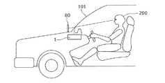
図2は、本実施の形態に係る表示装置の車両内における配置例を示す模式図である。 FIG. 2 is a schematic diagram showing an arrangement example of the display device according to the present embodiment in the vehicle.
図1に示されるように、表示装置1は、投射部10と、制御部20と取得部30とを備える。
As shown in FIG. 1, the
図1に示される表示装置1は、いわゆるヘッドアップディスプレイであり、図2に示されるように車室内に設けられる。表示装置1は、風防ガラス101に画像を投射し、風防ガラス101において反射された画像をユーザ200に視認させる。
The
図1及び図2に示される投射部10は、画像を投射することができる画像投射装置である。投射部10は、内部に光学系を備えた画像投射装置であり、例えば、図2に示されるように車両のダッシュボード内部に設けられる。なお、投射部10の内部の詳細な構成については、後述する。
The
投射部10は、透光性を有する表示媒体である風防ガラス101に向けて光を投射し、風防ガラス101における反射を利用して位置80に画像(虚像)を結像させることができる。
The
図1に示される取得部30は、車両から当該車両に関する情報を取得する。車両に関する情報は、具体的には、車速情報などである。なお、取得部30は、スマートフォンや、車両内に設けられたカーナビゲーション装置など、表示装置1とは異なる装置から情報を取得してもよい。また、取得部30の情報の取得には、有線又は無線のどのような通信ネットワーク(又は、通信インターフェース)が用いられてもよい。
The
図1に示される制御部20は、取得部30が取得した情報に応じて投射部10に投射させる画像を調整する処理部である。制御部20は、例えば、取得部30が取得した情報に基づいて、ナビゲーション用の矢印を含む画像や、スピードメータを含む画像などを投射させる。
The
制御部20は、具体的には、プロセッサである。なお、制御部20は、ハードウェアのみで構成されてもよいし、ハードウェアとソフトウェアとを組み合わせることにより実現されてもよい。制御部20は、例えば、マイコンなどでも実現できる。
Specifically, the
[1−2.投射部の構成]
次に、本実施の形態に係る表示装置1の投射部10の構成について詳細に説明する。
[1-2. Configuration of projection unit]
Next, the configuration of the
図3は、本実施の形態に係る投射部10の内部構成を示す模式図である。
FIG. 3 is a schematic diagram illustrating an internal configuration of the
図3には、画像(画像を構成する光)を投射する投射部10とともに、投射部10からの画像が投射される表示媒体である風防ガラス101が示される。
FIG. 3 shows a
図3に示されるように、投射部10は、第1のミラー11と、第2のミラー12と、表示部13と、ビームスプリッタ14と、を備える。
As shown in FIG. 3, the
図3に示される表示部13は、投射部10から投射される画像を生成する画像生成部である。表示部13は、例えば、液晶パネルなどから構成される。本実施の形態においては、表示部13は、第1のミラー11で反射させるための第1の画像(画像を構成する光)と、ビームスプリッタ14で反射させるための第2の画像(画像を構成する光)とを、交互に出射する。
The
図3に示される第2のミラー12は、投射部10の光学系を構成するミラーであり、表示部13から入射された画像をビームスプリッタ14に向けて反射する。第2のミラー12は、平面ミラーであってもよいし、光学倍率、及び、表示部13から出射される画像を構成する光の発散角、及び、投射部10の他の光学素子の形状等に応じた曲率半径や曲面形状を有してもよい。第2のミラー12の反射面等を構成する材料としては、表示部13から入射される画像を反射できる任意の材料を採用することができる。
The
図3に示されるビームスプリッタ14は、投射部10の光学系を構成する光学素子であり、第2のミラー12から入射された画像のうち、上記第1の画像を透過させ、かつ、上記第2の画像を風防ガラス101に向けて反射する。本実施の形態においては、ビームスプリッタ14は、画像の透過及び反射を切り替えることができる光スイッチを用いる。ここで、光スイッチとしては、例えば、透過及び反射を印加電圧によって切り替えることができるスイッチャブルホログラムなどを用いることができる。また、ビームスプリッタ14の反射率(及び透過率)は、上記第1の画像を透過し、上記第2の画像を反射するようなタイミングで切り替えられる。
The
図3に示される第1のミラー11は、投射部10の光学系を構成するミラーであり、ビームスプリッタ14を透過した画像が入射され、当該入射された画像を風防ガラス101に向けて反射する。第1のミラー11は、平面ミラーであってもよいし、凹面ミラーであってもよい。また、第1のミラー11を凹面ミラーとする場合は、ビームスプリッタ14として、反射光に対して集光力を持ち、透過光に対して集光力を持たない素子を用いてもよい。第1のミラー11の反射面等を構成する材料としては、表示部13から入射される画像を反射できる任意の材料を採用することができる。
The
[1−3.表示装置の表示方法]
次に、以上で述べた表示装置1における表示方法について、図4を用いて説明する。
[1-3. Display device display method]
Next, a display method in the
図4は、表示装置1の動作概要を示すフローチャートである。
FIG. 4 is a flowchart showing an outline of the operation of the
まず、投射部10の光学系が所定の位置にセットされる(S1)。ここで、当該光学系には、第1のミラー11と、第2のミラー12と、ビームスプリッタ14とが含まれる。
First, the optical system of the
次に、制御部20から表示部13に向けて表示すべき画像の情報が出力され、当該画像の情報に基づいて表示部13から第2のミラー12に向けて画像が出射される(S2)。ここで、当該画像の情報には、上述した第1の画像及び第2の画像を生成するための情報が含まれ、表示部13が出射する画像には、第1の画像及び第2の画像が含まれる。また、本実施の形態においては、表示部13は、第1の画像及び第2の画像を、互いに異なるタイミングで交互に出射する。
Next, information on the image to be displayed is output from the
次に、第2のミラー12は、表示部13から入射された画像を、ビームスプリッタ14に向けて反射する(S3)。そして、ビームスプリッタ14に画像が入射される(S4)。
Next, the
ビームスプリッタ14に画像が入射されるとき、第1の画像が入射されるタイミングであれば(S5でYes)、ビームスプリッタ14は、制御部20によって透過率を高められることによって、第1の画像を透過させる(S6)。ビームスプリッタ14を透過した第1の画像は、第1のミラー11に入射され、入射された第1の画像は、第1のミラー11によって反射されることによって風防ガラス101に投射される(S7)。一方、ビームスプリッタ14に第1の画像が入射されるタイミングでなければ(S5でNo)、ビームスプリッタ14は、制御部20によって反射率を高められることによって、第2の画像を風防ガラス101へ向けて反射する。これにより、第2の画像は風防ガラス101に投射される(S8)。
When the image is incident on the
以上のように、本実施の形態においては、表示部13から出射された画像が、第1の画像及び第2の画像に分離されて、それぞれ、第1のミラー11及びビームスプリッタ14から風防ガラス101に投射される。したがって、第1の画像及び第2の画像を風防ガラス101の異なる領域に投射することで、ユーザ200に視認される表示画像の鉛直方向における寸法を拡大することができる。しかも、本実施の形態においては、第1の画像及び第2の画像の光路が一部共通化されているため、光学系の拡大が抑制される。
As described above, in the present embodiment, the image emitted from the
本実施の形態においては、表示部13によって、第1の画像と第2の画像とを、交互に高速に切り替えてもよい。これにより、ユーザ200の眼には、第1の画像と第2の画像とが同時に表示されているかのように視認される。
In the present embodiment, the
なお、本実施の形態においては、第2のミラー12を用いる構成を示したが、第2のミラー12を用いなくてもよい。すなわち、表示部13から出射される画像を直接ビームスプリッタ14に入射してもよい。これにより、光学系を簡素化することができる。
In the present embodiment, the configuration using the
(実施の形態2)
次に、実施の形態2に係る表示装置について説明する。
(Embodiment 2)
Next, a display device according to
上記実施の形態1においては、互いに異なるタイミングで第1の画像及び第2の画像がビームスプリッタに入射される構成として、第1の画像と第2の画像とを分離した。これに対して、本実施の形態においては、互いに異なる波長分布を有する第1の画像と第2の画像とを用いることによって、第1の画像と第2の画像とを分離する。 In the first embodiment, the first image and the second image are separated as a configuration in which the first image and the second image are incident on the beam splitter at different timings. In contrast, in the present embodiment, the first image and the second image are separated by using the first image and the second image having different wavelength distributions.
本実施の形態は、上記実施の形態1と投射部の構成において主に相違するため、以下、投射部について詳述し、その他の構成については説明を省略する。 Since the present embodiment is mainly different from the first embodiment in the configuration of the projection unit, the projection unit will be described in detail below, and description of the other configurations will be omitted.
[2−1.投射部の構成]
本実施の形態に係る投射部の構成について図5及び図6を用いて説明する。
[2-1. Configuration of projection unit]
The configuration of the projection unit according to the present embodiment will be described with reference to FIGS.
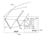
図5は、本実施の形態に係る投射部10aの内部構成を示す模式図である。
FIG. 5 is a schematic diagram showing an internal configuration of the
図5に示されるように、投射部10aは、第1のミラー11と、表示部13aと、ビームスプリッタ14aと、を備える。
As illustrated in FIG. 5, the
図5に示される表示部13aは、投射部10aから投射される画像を生成する画像生成部である。図5に示されるように、表示部13aは、第1の表示素子131a及び第2の表示素子131bと、第1の光源132a及び第2の光源132bと、合波器133とを備える。
The
表示部13aの第1の光源132a及び第2の光源132bは、それぞれ、第1の表示素子131a及び第2の表示素子131bに光を出力する光源である。本実施の形態においては、第1の光源132a及び第2の光源132bは、互いに異なる波長分布を有する。第1の光源132aは、主に、波長B1の青色光、波長G1の緑色光及び波長R1の赤色光を出力する光源である。また、第2の光源132bは、主に、波長B2(≠B1)の青色光、波長G2(≠G1)の緑色光及び波長R2(≠G1)の赤色光を出力する光源である。上記各光源としては、例えば、各波長のレーザ光を出力する半導体レーザ素子、固体レーザ素子などを組み合わせた光源を用いることができる。
The
表示部13aの第1の表示素子131a及び第2の表示素子131bは、例えば、液晶パネルなどから構成される。本実施の形態においては、第1の表示素子131aは、第1のミラー11で反射させるための第1の画像(画像を構成する光)を出力し、第2の表示素子131bは、ビームスプリッタ14aで反射させるための第2の画像(画像を構成する光)を出力する。
The
表示部13aの合波器133は、第1の表示素子131aから入力された第1の画像、及び、第2の表示素子131bから入力された第2の画像を合波して、ビームスプリッタ14aに向けて出射する光学素子である。ここで、合波器133の反射波長特性について図6を用いて説明する。
The
図6は、合波器133の反射波長特性の概要を示す図である。図6に示されるように、合波器133は、第2の光源132b(及び第2の表示素子131b)から出力される光の波長帯域においてを高い反射率を有し、第1の光源132a(及び第1の表示素子131a)から出力される光の波長帯域において低い反射率を有する。これにより、合波器133は、第2の表示素子131bから出射される第2の画像だけを反射する。また、この際、合波器133は、第2の画像の進行方向を90度偏向させる。これにより、合波器133は、第1の画像及び第2の画像を合波して出力することができる。このような特性を有する合波器133は、例えば、ホログラムを用いて実現することができる。
FIG. 6 is a diagram showing an outline of the reflected wavelength characteristic of the
図5に示されるビームスプリッタ14aは、合波器133から出射された第1の画像及び第2の画像のうち、上記第1の画像を透過させ、かつ、上記第2の画像を風防ガラス101に向けて反射する光学素子である。本実施の形態においては、ビームスプリッタ14aは、上記の合波器133と同様の反射波長特性(図6)を有する光学素子によって構成される。したがって、ビームスプリッタ14aとして、例えば、合波器133と同一の光学素子を用いてもよい。
The
図5に示される第1のミラー11は、上記実施の形態1の投射部10において用いられるものと同様であるため、説明を省略する。
Since the
[2−2.表示装置の表示方法]
次に、以上で述べた本実施の形態に係る表示装置における表示方法について、図7を用いて説明する。
[2-2. Display device display method]
Next, a display method in the display device according to this embodiment described above will be described with reference to FIG.
図7は、本実施の形態の表示装置の動作概要を示すフローチャートである。 FIG. 7 is a flowchart showing an outline of the operation of the display device of the present embodiment.
まず、投射部10aの光学系が所定の位置にセットされる(S11)。ここで、当該光学系には、第1のミラー11と、ビームスプリッタ14aとが含まれる。
First, the optical system of the
次に、制御部20から表示部13aに向けて表示すべき画像の情報が出力される。そして、その情報に基づいて、第1の光源132a及び第2の光源132b、並びに、第1の表示素子131a及び第2の表示素子131bが駆動され、第1の表示素子131a及び第2の表示素子131bから、それぞれ、第1の画像及び第2の画像が出力される(S12)。
Next, information on an image to be displayed is output from the
次に、第1の表示素子131aから出力された第1の画像及び第2の表示素子131bから出力された第2の画像が合波器133に入力され(S13)、合波器133によって合波された後(S14)、ビームスプリッタ14aへ向けて出射される(S15)。そして、ビームスプリッタ14aに第1の画像及び第2の画像が入射される(S16)。
Next, the first image output from the
ビームスプリッタ14aは、入射された画像のうち、第1の画像を透過させ、かつ、第2の画像を反射させることによって風防ガラス101に投射する(S17)。
The
ビームスプリッタ14aを透過した第1の画像は、第1のミラー11に入射され、第1のミラー11によって反射されることによって風防ガラス101に投射される(S18)。
The first image transmitted through the
以上のように、本実施の形態においては、表示部13aから出射された第1の画像及び第2の画像が、ビームスプリッタ14aによって分離されて、それぞれ、第1のミラー11及びビームスプリッタ14aから風防ガラス101に投射される。したがって、第1の画像及び第2の画像の風防ガラス101への投射領域を互いに異なる領域に設定することで、ユーザ200に視認される表示画像の鉛直方向における寸法を拡大することができる。しかも、本実施の形態においては、第1の画像及び第2の画像の光路が一部共通化されているため、光学系の拡大が抑制される。
As described above, in the present embodiment, the first image and the second image emitted from the
さらに、本実施の形態においては、第1の画像及び第2の画像を同時に表示することができる。 Furthermore, in the present embodiment, the first image and the second image can be displayed simultaneously.
また、本実施の形態においては、第1の画像及び第2の画像とも、カラー画像となるように主に三つの波長帯域の光で構成したが、各画像の有する波長分布はこれに限られない。例えば、各画像を互いに異なる一つの波長帯域の光で構成してもよい。 In the present embodiment, the first image and the second image are mainly composed of light of three wavelength bands so as to be color images. However, the wavelength distribution of each image is limited to this. Absent. For example, each image may be composed of light of one different wavelength band.
また、本実施の形態においては、上記実施の形態1で用いられた第2のミラーを用いない構成を示したが、本実施の形態においても第2のミラーを表示部13aとビームスプリッタ14aとの間に設けてもよい。これにより、光学系の設計の自由度が向上する。
Further, in the present embodiment, a configuration in which the second mirror used in the first embodiment is not used is shown. However, in the present embodiment as well, the second mirror is connected to the
(その他の実施の形態)
以上のように、本発明の例示として、実施の形態1及び実施の形態2を説明した。しかしながら、本発明は、これに限定されず、適宜、変更、置き換え、付加、省略などを行った実施の形態にも適用可能である。また、上記各実施の形態で説明した各構成要素を組み合わせて、新たな実施の形態とすることも可能である。
(Other embodiments)
As described above,
例えば、上記各実施の形態においては、第1の画像及び第2の画像を投射する透光性を有する表示媒体として風防ガラス101を用いる構成を示したが、表示媒体としては、これに限られない。例えば、一つ又は複数のコンバイナを用いてもよい。
For example, in each of the above-described embodiments, the configuration in which the
また、上記各実施の形態において、第1の画像及び第2の画像を隣接させて表示することも、分離して表示することも可能である。例えば、風防ガラス101の下端部付近に第1の画像を、上端部付近に第2の画像を、それぞれ投射してもよい。これによれば、ユーザ200の前方の視界を妨げることを抑制することができる。
In each of the above embodiments, the first image and the second image can be displayed adjacent to each other or can be displayed separately. For example, the first image may be projected near the lower end of the
また、上記実施の形態2においては、第1の画像及び第2の画像が互いに異なる波長分布の光からなる構成を示したが、第1の画像及び第2の画像が、互いに異なる偏光方向の光からなる構成を用いることも可能である。この場合、合波器及びビームスプリッタとしては、偏光ビームスプリッタを用いることができる。 In the second embodiment, the first image and the second image are composed of light having different wavelength distributions. However, the first image and the second image have different polarization directions. It is also possible to use a configuration made of light. In this case, a polarization beam splitter can be used as the multiplexer and the beam splitter.
また、本発明の表示装置において、第1の画像及び第2の画像として、それぞれ、二次元画像及び三次元画像のいずれを用いてもよい。 In the display device of the present invention, either a two-dimensional image or a three-dimensional image may be used as the first image and the second image, respectively.
また、上記各実施の形態に係る表示装置は、車両以外の輸送用機器(例えば、飛行機、船舶など)に設けられてもよい。 In addition, the display device according to each of the above embodiments may be provided in a transportation device other than a vehicle (for example, an airplane, a ship, or the like).
また、上記実施の形態において、各構成要素は、専用のハードウェアで構成されるか、各構成要素に適したソフトウェアプログラムを実行することによって実現されてもよい。各構成要素は、CPU又はプロセッサなどのプログラム実行部が、ハードディスク又は半導体メモリなどの記録媒体に記録されたソフトウェアプログラムを読み出して実行することによって実現されてもよい。 In the above-described embodiment, each component may be configured by dedicated hardware or may be realized by executing a software program suitable for each component. Each component may be realized by a program execution unit such as a CPU or a processor reading and executing a software program recorded on a recording medium such as a hard disk or a semiconductor memory.
以上、一つ又は複数の態様に係る表示装置(表示方法)について、実施の形態1及び実施の形態2に基づいて説明したが、本発明は、これらの実施の形態に限定されるものではない。本発明の趣旨を逸脱しない限り、当業者が思いつく各種変形を上記各実施の形態に施したものや、異なる実施の形態における構成要素を組み合わせて構築される形態も、一つ又は複数の態様の範囲内に含まれてもよい。 As described above, the display device (display method) according to one or a plurality of aspects has been described based on the first embodiment and the second embodiment, but the present invention is not limited to these embodiments. . Unless it deviates from the gist of the present invention, various modifications conceived by those skilled in the art have been made in the above embodiments, and forms constructed by combining components in different embodiments are also in one or more aspects. It may be included within the range.
例えば、上記各実施の形態において、特定の処理部が実行する処理を別の処理部が実行してもよい。また、複数の処理の順序が変更されてもよいし、複数の処理が並行して実行されてもよい。 For example, in each of the above embodiments, a process executed by a specific processing unit may be executed by another processing unit. Further, the order of the plurality of processes may be changed, and the plurality of processes may be executed in parallel.
本発明は、車両用のヘッドアップディスプレイとして有用である。 The present invention is useful as a head-up display for a vehicle.
1 表示装置
10、10a、300 投射部
11、301 第1のミラー
12、302 第2のミラー
13、13a、303 表示部
14、14a ビームスプリッタ
20 制御部
30 取得部
80 位置
101 風防ガラス
131a 第1の表示素子
131b 第2の表示素子
132a 第1の光源
132b 第2の光源
133 合波器
200 ユーザ
DESCRIPTION OF
Claims (10)
前記表示部から出射された前記第1の画像及び前記第2の画像が入射され、入射された前記第1の画像を透過させて、かつ、入射された前記第2の画像を反射することによって表示媒体に投射するビームスプリッタと、
前記ビームスプリッタを透過した前記第1の画像が入射され、入射された前記第1の画像を反射することによって前記表示媒体に投射する第1のミラーと、
前記表示部から出射された前記第1の画像及び前記第2の画像を前記ビームスプリッタに向けて反射する第2のミラーと、を備える
表示装置。 A display unit for emitting the first image and the second image;
By entering the first image and the second image emitted from the display unit, transmitting the incident first image, and reflecting the incident second image A beam splitter that projects onto a display medium;
A first mirror that is incident on the first image transmitted through the beam splitter and that projects the incident first image onto the display medium by reflecting the first image;
And a second mirror that reflects the first image and the second image emitted from the display unit toward the beam splitter .
請求項1に記載の表示装置。 The display device according to claim 1, wherein the first image and the second image are projected onto different areas of the display medium.
前記第1の画像を出力する第1の表示素子と、
前記第2の画像を出力する第2の表示素子と、
前記第1の表示素子から出力された前記第1の画像、及び、前記第2の表示素子から出力された前記第2の画像を合波した後、出射する合波器と、を備える
請求項1又は2に記載の表示装置。 The display unit
A first display element for outputting the first image;
A second display element for outputting the second image;
A combiner that outputs the first image output from the first display element and the second image output from the second display element, and then outputs the combined image. The display device according to 1 or 2 .
請求項1〜3のいずれか1項に記載の表示装置。 Said first mirror, a display device according to any one of claims 1 to 3 having a Atsumarihikariryoku.
請求項4に記載の表示装置。 The display device according to claim 4 , wherein the beam splitter has a light collecting power for reflected light and does not have a light collecting power for transmitted light.
前記ビームスプリッタの反射率は、前記第1の画像を透過し、前記第2の画像を反射するように切り替えられる
請求項1〜5のいずれか1項に記載の表示装置。 The first image and the second image are emitted from the display unit at different timings,
Reflectance of the beam splitter, the first image transmitted through the display device according to any one of the second image 1 to claim switched to reflect 5.
前記ビームスプリッタは波長選択ミラーである
請求項1〜5のいずれか1項に記載の表示装置。 The first image and the second image have different light wavelength distributions,
The beam splitter display device according to any one of claims 1 to 5, which is a wavelength selective mirror.
請求項7に記載の表示装置。 The display device according to claim 7 , wherein the wavelength selection mirror is a hologram.
前記ビームスプリッタは、偏光ビームスプリッタである
請求項1〜5のいずれか1項に記載の表示装置。 The first image and the second image are made of light having different polarization directions,
Said beam splitter, a display device according to any one of claims 1 to 5 which is a polarization beam splitter.
第1のミラーと、第2のミラーと、を備える表示装置の表示方法であって、
前記表示装置にビームスプリッタを設け、
前記表示部に第1の画像及び第2の画像を出射させ、
前記表示部から出射された前記第1の画像及び前記第2の画像を前記第2のミラーによって前記ビームスプリッタに向けて反射し、
前記表示部から出射された前記第1の画像及び前記第2の画像を前記ビームスプリッタに入射し、
前記ビームスプリッタに前記第1の画像を透過させ、かつ、前記ビームスプリッタに前記第2の画像を反射させることによって表示媒体に投射し、
前記ビームスプリッタを透過した前記第1の画像を前記第1のミラーに入射し、入射された前記第1の画像を前記第1のミラーに反射させることによって前記表示媒体に投射する
表示方法。 A display unit;
A display method of a display device comprising a first mirror and a second mirror ,
A beam splitter is provided in the display device,
Causing the display unit to emit a first image and a second image;
The first image and the second image emitted from the display unit are reflected by the second mirror toward the beam splitter,
The first image and the second image emitted from the display unit are incident on the beam splitter;
Projecting the first image to the beam splitter and projecting the second image to the display medium by reflecting the second image to the beam splitter;
A display method in which the first image transmitted through the beam splitter is incident on the first mirror, and the incident first image is reflected on the first mirror to be projected onto the display medium.
Priority Applications (4)
| Application Number | Priority Date | Filing Date | Title |
|---|---|---|---|
| JP2014098925A JP6238072B2 (en) | 2014-05-12 | 2014-05-12 | Display device and display method thereof |
| EP15792724.5A EP3144716B1 (en) | 2014-05-12 | 2015-05-08 | Display device, and display method therefor |
| PCT/JP2015/002334 WO2015174048A1 (en) | 2014-05-12 | 2015-05-08 | Display device, and display method therefor |
| US15/308,357 US9927610B2 (en) | 2014-05-12 | 2015-05-08 | Display device, and display method therefor |
Applications Claiming Priority (1)
| Application Number | Priority Date | Filing Date | Title |
|---|---|---|---|
| JP2014098925A JP6238072B2 (en) | 2014-05-12 | 2014-05-12 | Display device and display method thereof |
Publications (2)
| Publication Number | Publication Date |
|---|---|
| JP2015215515A JP2015215515A (en) | 2015-12-03 |
| JP6238072B2 true JP6238072B2 (en) | 2017-11-29 |
Family
ID=54479599
Family Applications (1)
| Application Number | Title | Priority Date | Filing Date |
|---|---|---|---|
| JP2014098925A Active JP6238072B2 (en) | 2014-05-12 | 2014-05-12 | Display device and display method thereof |
Country Status (4)
| Country | Link |
|---|---|
| US (1) | US9927610B2 (en) |
| EP (1) | EP3144716B1 (en) |
| JP (1) | JP6238072B2 (en) |
| WO (1) | WO2015174048A1 (en) |
Families Citing this family (13)
| Publication number | Priority date | Publication date | Assignee | Title |
|---|---|---|---|---|
| CN105824123A (en) * | 2016-05-13 | 2016-08-03 | 深圳中科呼图信息技术有限公司 | Reality augmentation head-mounted device |
| KR101912499B1 (en) * | 2016-05-23 | 2018-12-28 | 엘지전자 주식회사 | Head Up Display for Vehicle |
| KR101928139B1 (en) * | 2016-06-16 | 2018-12-11 | 한양대학교 산학협력단 | Head-Up Display Device |
| FR3054327B1 (en) * | 2016-07-22 | 2021-01-01 | Valeo Comfort & Driving Assistance | HEAD-UP DISPLAY |
| KR101899981B1 (en) * | 2016-12-02 | 2018-09-19 | 엘지전자 주식회사 | Head Up Display for Vehicle |
| CN108656952B (en) * | 2017-04-01 | 2021-02-09 | 宁波舜宇车载光学技术有限公司 | Vehicle-mounted information display device, vehicle-mounted information display method and transportation tool |
| EP3608703A4 (en) * | 2017-04-06 | 2020-12-23 | LG Electronics Inc. -1- | Head up display apparatus for vehicle |
| FR3076913B1 (en) * | 2018-01-17 | 2021-04-09 | Valeo Comfort & Driving Assistance | HEAD-UP DISPLAY FOR MOTOR VEHICLES AND DRIVING ASSISTANCE SYSTEM INCLUDING SUCH DISPLAY |
| TWM567693U (en) * | 2018-01-18 | 2018-10-01 | 禾龍有限公司 | Tool capable of quickly and safely replacing and securing positioned blade and shank structure thereof |
| US11320901B2 (en) | 2018-05-31 | 2022-05-03 | Boe Technology Group Co., Ltd. | Head-up display system and display method, vehicle, head-up display device, and computer-readable storage medium |
| DE102020103824A1 (en) | 2020-02-13 | 2021-08-19 | Bayerische Motoren Werke Aktiengesellschaft | Projection unit for a field of view display device in a vehicle |
| CN114063290A (en) * | 2020-08-07 | 2022-02-18 | 东莞创奕电子科技有限公司 | Head-up display system for vehicle |
| US20220055479A1 (en) * | 2020-08-24 | 2022-02-24 | Conserve & Associates , Inc. | Vehicular head-up display system with virtual images in different distances |
Family Cites Families (12)
| Publication number | Priority date | Publication date | Assignee | Title |
|---|---|---|---|---|
| US4987410A (en) * | 1988-01-25 | 1991-01-22 | Kaiser Aerospace & Electronics Corporation | Multiple image forming apparatus |
| IL88931A (en) * | 1988-01-25 | 1992-05-25 | Kaiser Aerospace & Electronics | Multiple image-forming apparatus |
| JP3651808B2 (en) * | 1993-12-08 | 2005-05-25 | 大日本印刷株式会社 | Method for producing color Lippmann hologram |
| JP4731938B2 (en) * | 2004-05-13 | 2011-07-27 | 株式会社リコー | Image display device / projection optical system |
| JP2005338689A (en) * | 2004-05-31 | 2005-12-08 | Nippon Seiki Co Ltd | Reflecting mirror and reflecting mirror device equipped with the reflecting mirror |
| TWI311232B (en) * | 2006-10-05 | 2009-06-21 | Delta Electronics Inc | Light processing structure for a digital light processing projection device |
| WO2010051979A1 (en) | 2008-11-05 | 2010-05-14 | Johnson Controls Gmbh | Vehicle display system or projection display for a motor vehicle, and calibration method |
| US20100231868A1 (en) * | 2009-03-13 | 2010-09-16 | Alvis Technologies Inc. | Display device |
| JP2010276689A (en) * | 2009-05-26 | 2010-12-09 | Nippon Seiki Co Ltd | Head-up display device |
| JP2012163705A (en) | 2011-02-04 | 2012-08-30 | Denso Corp | Head-up display device |
| CN103728821B (en) * | 2012-10-12 | 2015-10-28 | 扬明光学股份有限公司 | Projection arrangement |
| JPWO2015159523A1 (en) * | 2014-04-14 | 2017-04-13 | パナソニックIpマネジメント株式会社 | Head-up display and mobile body equipped with head-up display |
-
2014
- 2014-05-12 JP JP2014098925A patent/JP6238072B2/en active Active
-
2015
- 2015-05-08 EP EP15792724.5A patent/EP3144716B1/en active Active
- 2015-05-08 WO PCT/JP2015/002334 patent/WO2015174048A1/en active Application Filing
- 2015-05-08 US US15/308,357 patent/US9927610B2/en active Active
Also Published As
| Publication number | Publication date |
|---|---|
| JP2015215515A (en) | 2015-12-03 |
| EP3144716A1 (en) | 2017-03-22 |
| WO2015174048A1 (en) | 2015-11-19 |
| EP3144716B1 (en) | 2020-02-26 |
| EP3144716A4 (en) | 2017-09-27 |
| US20170059863A1 (en) | 2017-03-02 |
| US9927610B2 (en) | 2018-03-27 |
Similar Documents
| Publication | Publication Date | Title |
|---|---|---|
| JP6238072B2 (en) | Display device and display method thereof | |
| JP6238151B1 (en) | Head-up display device and vehicle | |
| JP6603883B2 (en) | Head-up display and mobile body equipped with head-up display | |
| JP6473895B2 (en) | Head-up display and mobile body equipped with head-up display | |
| JP6260345B2 (en) | Intermediate image forming unit and image display apparatus using the same | |
| JP6382305B2 (en) | Head-up display device | |
| WO2015159523A1 (en) | Heads-up display and moving body equipped with heads-up display | |
| JP6597196B2 (en) | Virtual image display measures | |
| JP6601431B2 (en) | Head-up display device | |
| US11092804B2 (en) | Virtual image display device | |
| KR20190072649A (en) | Virtual image display device | |
| CN113661432B (en) | Head-up display device | |
| JP6593461B2 (en) | Virtual image display device | |
| JP2021154998A (en) | Display device | |
| WO2020195404A1 (en) | Video display system, video display method, program, and moving body | |
| JP7111070B2 (en) | head-up display device | |
| JP7111071B2 (en) | head-up display device | |
| JP6593393B2 (en) | Virtual image display device | |
| JP6593463B2 (en) | Virtual image display device | |
| JP2015219389A (en) | Virtual image display device and image forming element | |
| US9910277B2 (en) | Head-up display | |
| JP2016218350A (en) | Head-up display device | |
| JP2018040921A (en) | Display device |
Legal Events
| Date | Code | Title | Description |
|---|---|---|---|
| A621 | Written request for application examination |
Free format text: JAPANESE INTERMEDIATE CODE: A621 Effective date: 20161221 |
|
| A131 | Notification of reasons for refusal |
Free format text: JAPANESE INTERMEDIATE CODE: A131 Effective date: 20170808 |
|
| A521 | Request for written amendment filed |
Free format text: JAPANESE INTERMEDIATE CODE: A523 Effective date: 20171005 |
|
| TRDD | Decision of grant or rejection written | ||
| A01 | Written decision to grant a patent or to grant a registration (utility model) |
Free format text: JAPANESE INTERMEDIATE CODE: A01 Effective date: 20171010 |
|
| A61 | First payment of annual fees (during grant procedure) |
Free format text: JAPANESE INTERMEDIATE CODE: A61 Effective date: 20171018 |
|
| R151 | Written notification of patent or utility model registration |
Ref document number: 6238072 Country of ref document: JP Free format text: JAPANESE INTERMEDIATE CODE: R151 |
|
| S111 | Request for change of ownership or part of ownership |
Free format text: JAPANESE INTERMEDIATE CODE: R313113 |
|
| S531 | Written request for registration of change of domicile |
Free format text: JAPANESE INTERMEDIATE CODE: R313531 |
|
| SZ03 | Written request for cancellation of trust registration |
Free format text: JAPANESE INTERMEDIATE CODE: R313Z03 |