JP6237904B2 - Ice making equipment - Google Patents
Ice making equipment Download PDFInfo
- Publication number
- JP6237904B2 JP6237904B2 JP2016535953A JP2016535953A JP6237904B2 JP 6237904 B2 JP6237904 B2 JP 6237904B2 JP 2016535953 A JP2016535953 A JP 2016535953A JP 2016535953 A JP2016535953 A JP 2016535953A JP 6237904 B2 JP6237904 B2 JP 6237904B2
- Authority
- JP
- Japan
- Prior art keywords
- ice making
- ice
- cylinder
- chamber
- water
- Prior art date
- Legal status (The legal status is an assumption and is not a legal conclusion. Google has not performed a legal analysis and makes no representation as to the accuracy of the status listed.)
- Active
Links
- XLYOFNOQVPJJNP-UHFFFAOYSA-N water Substances O XLYOFNOQVPJJNP-UHFFFAOYSA-N 0.000 claims description 91
- 230000002093 peripheral effect Effects 0.000 claims description 25
- 238000005057 refrigeration Methods 0.000 claims description 11
- 230000007246 mechanism Effects 0.000 claims description 9
- 238000001816 cooling Methods 0.000 claims description 5
- 239000005457 ice water Substances 0.000 claims 1
- 239000011810 insulating material Substances 0.000 description 12
- 239000003507 refrigerant Substances 0.000 description 11
- 238000005187 foaming Methods 0.000 description 9
- 230000000694 effects Effects 0.000 description 7
- 239000007788 liquid Substances 0.000 description 6
- 230000008878 coupling Effects 0.000 description 5
- 238000010168 coupling process Methods 0.000 description 5
- 238000005859 coupling reaction Methods 0.000 description 5
- 239000002184 metal Substances 0.000 description 5
- 239000002984 plastic foam Substances 0.000 description 5
- 239000011550 stock solution Substances 0.000 description 5
- 238000001125 extrusion Methods 0.000 description 4
- 238000007710 freezing Methods 0.000 description 4
- 230000008014 freezing Effects 0.000 description 4
- 238000003756 stirring Methods 0.000 description 4
- 238000006243 chemical reaction Methods 0.000 description 3
- 238000001704 evaporation Methods 0.000 description 3
- 230000008020 evaporation Effects 0.000 description 3
- 230000001141 propulsive effect Effects 0.000 description 3
- 230000015572 biosynthetic process Effects 0.000 description 2
- 230000006835 compression Effects 0.000 description 2
- 238000007906 compression Methods 0.000 description 2
- 238000001514 detection method Methods 0.000 description 2
- 238000003780 insertion Methods 0.000 description 2
- 230000037431 insertion Effects 0.000 description 2
- 238000000034 method Methods 0.000 description 2
- 230000008569 process Effects 0.000 description 2
- 229910001220 stainless steel Inorganic materials 0.000 description 2
- 239000010935 stainless steel Substances 0.000 description 2
- 238000013459 approach Methods 0.000 description 1
- 238000005452 bending Methods 0.000 description 1
- 230000009172 bursting Effects 0.000 description 1
- 230000008859 change Effects 0.000 description 1
- 239000003638 chemical reducing agent Substances 0.000 description 1
- 239000011162 core material Substances 0.000 description 1
- 230000007613 environmental effect Effects 0.000 description 1
- 238000010097 foam moulding Methods 0.000 description 1
- 238000010438 heat treatment Methods 0.000 description 1
- 238000009434 installation Methods 0.000 description 1
- 238000009413 insulation Methods 0.000 description 1
- 239000012212 insulator Substances 0.000 description 1
- 239000000463 material Substances 0.000 description 1
- 235000013372 meat Nutrition 0.000 description 1
- 230000004048 modification Effects 0.000 description 1
- 238000012986 modification Methods 0.000 description 1
- 238000012856 packing Methods 0.000 description 1
- 238000005476 soldering Methods 0.000 description 1
- 239000007787 solid Substances 0.000 description 1
- 239000008399 tap water Substances 0.000 description 1
- 235000020679 tap water Nutrition 0.000 description 1
- 238000004804 winding Methods 0.000 description 1
Images


Classifications
-
- F—MECHANICAL ENGINEERING; LIGHTING; HEATING; WEAPONS; BLASTING
- F25—REFRIGERATION OR COOLING; COMBINED HEATING AND REFRIGERATION SYSTEMS; HEAT PUMP SYSTEMS; MANUFACTURE OR STORAGE OF ICE; LIQUEFACTION SOLIDIFICATION OF GASES
- F25C—PRODUCING, WORKING OR HANDLING ICE
- F25C1/00—Producing ice
- F25C1/22—Construction of moulds; Filling devices for moulds
-
- F—MECHANICAL ENGINEERING; LIGHTING; HEATING; WEAPONS; BLASTING
- F25—REFRIGERATION OR COOLING; COMBINED HEATING AND REFRIGERATION SYSTEMS; HEAT PUMP SYSTEMS; MANUFACTURE OR STORAGE OF ICE; LIQUEFACTION SOLIDIFICATION OF GASES
- F25C—PRODUCING, WORKING OR HANDLING ICE
- F25C5/00—Working or handling ice
- F25C5/14—Apparatus for shaping or finishing ice pieces, e.g. ice presses
- F25C5/142—Apparatus for shaping or finishing ice pieces, e.g. ice presses extrusion of ice crystals
Landscapes
- Engineering & Computer Science (AREA)
- Physics & Mathematics (AREA)
- Mechanical Engineering (AREA)
- Thermal Sciences (AREA)
- General Engineering & Computer Science (AREA)
- Chemical & Material Sciences (AREA)
- Crystallography & Structural Chemistry (AREA)
- Production, Working, Storing, Or Distribution Of Ice (AREA)
Description
この発明は、圧縮機と凝縮器と膨張機構と蒸発器とからなる冷凍サイクルを有する製氷装置に関する。 The present invention relates to an ice making device having a refrigeration cycle including a compressor, a condenser, an expansion mechanism, and an evaporator.
この種の圧縮機と凝縮器と膨張機構と蒸発器とからなる冷凍サイクルを有する製氷装置として、オーガ式製氷機が知られている(例えば、特許文献1)。このオーガ式製氷機は、供給された水から氷片を製氷する断熱構造の製氷部を備えている。 An auger type ice making machine is known as an ice making device having a refrigeration cycle including a compressor, a condenser, an expansion mechanism, and an evaporator of this type (for example, Patent Document 1). This auger type ice making machine includes an ice making part having a heat insulating structure for making ice pieces from supplied water.
製氷部は、円筒状の製氷筒の外周面に冷凍サイクルを構成するパイプ状の蒸発器が巻回されるとともにその周囲を断熱材で包囲されることにより断熱構造として形成されている。この製氷部は、製氷筒の底部に供給された水を冷凍サイクルの運転により製氷筒内壁面に着氷させる。その一方、製氷部は、製氷筒内に配設され、かつ減速機を介して連結された駆動モータにより回転するオーガ(スクリュー状の回転式切削刃)により、製氷筒内壁面に着氷した薄氷をフレーク状に切削して押し上げるとともにオーガの上方に設けられた氷圧縮用の押出しヘッドにより圧縮して固形化したうえで押出しヘッドの先端部で切断してチップ状の氷片を形成するように構成されている。 The ice making unit is formed as a heat insulating structure by winding a pipe-shaped evaporator constituting a refrigeration cycle around an outer peripheral surface of a cylindrical ice making cylinder and surrounding the periphery with a heat insulating material. The ice making unit causes the water supplied to the bottom of the ice making cylinder to be iced on the inner wall surface of the ice making cylinder by the operation of the refrigeration cycle. On the other hand, the ice making unit is disposed in the ice making cylinder and is thin ice that has landed on the inner wall surface of the ice making cylinder by an auger (screw-like rotary cutting blade) that is rotated by a drive motor connected via a speed reducer. In addition, it is cut into flakes and pushed up, and is compressed and solidified by an ice compression extrusion head provided above the auger, and then cut at the tip of the extrusion head to form chip-like ice pieces. It is configured.
この種のオーガ式製氷機においては、小型で製氷能力が高い点で優れている。しかしながら、オーガ式製氷機は、駆動モータの駆動力により製氷筒内壁面に着氷した薄氷をフレーク状に切削して押し上げるとともにオーガの上方に設けられた氷圧縮用の押出しヘッドにより圧縮して固形化するように構成されていることから次のような問題があった。 This type of auger type ice making machine is excellent in that it is small and has high ice making capacity. However, the auger type ice making machine cuts and pushes up the thin ice that has landed on the inner wall surface of the ice making cylinder into flakes by the driving force of the drive motor and compresses it by an ice compression extrusion head provided above the auger. There are the following problems because it is configured to be configured.
すなわち、オーガを駆動する駆動モータを必要とし、また押出しヘッドに氷が詰まると駆動モータがロックすることから駆動モータがロックすることがないように種々の対策を施さねばならないという問題があった。 That is, there is a problem that a drive motor for driving the auger is required, and that various measures must be taken so that the drive motor is not locked because the drive motor is locked when the extrusion head is clogged with ice.
本発明は上記実情に鑑みてなされたものであり、駆動源を必要とせずに固形化した氷を一方向に押出したうえでチップ状の氷片を形成することが可能な製氷装置を提供することを目的とする。 The present invention has been made in view of the above circumstances, and provides an ice making apparatus capable of forming chip-shaped ice pieces after extruding solid ice in one direction without requiring a drive source. For the purpose.
発明者らは上記課題を解決するため種々検討した結果、水が氷点下以下の温度で個体に変化する過程において体積が膨張する点に着目し、その体積膨張による圧力を、氷を一方向に押し出す推進力として利用することによって駆動源レスによりチップ状の氷片を形成する発明を得るに至ったものである。 As a result of various studies to solve the above problems, the inventors focused on the point that the volume expands in the process of water changing into an individual at a temperature below the freezing point, and pushes the pressure due to the volume expansion in one direction. By using it as a propulsive force, an invention has been obtained in which chip-shaped ice pieces are formed without a drive source.
上記目的を達成するために、本発明に係る製氷装置は、圧縮機と凝縮器と膨張機構と蒸発器からなる冷凍サイクルを有する製氷装置である。上下方向に直線的に延在する穴の上端に吐出口を有するとともに下部に製氷水の導入口を有する製氷室が形成された製氷筒体と、前記導入口を介して製氷室内に供給された製氷水を凍らせるように前記製氷筒体を冷却する蒸発器及び前記製氷筒体における製氷室の上方域に位置して当該製氷室の軸線を横切る氷片形成部を有するアイスブレーカーとを備えている。前記製氷筒体における製氷室は、下部側から上部側に向かうに従って断面積が漸増するテーパー状部分を有してなり、前記蒸発器による冷却により製氷水が氷に変化するときの体積膨張による圧力を、前記氷を押し上げる推進力として前記製氷室内を上方に進行する柱状の氷塊を形成し、製氷の進行により製氷室の吐出口から押し出された柱状の氷塊の進行方向をアイスブレーカーの氷片形成部に当接させて柱状の氷塊が破壊応力を超えて折れる態様で方向転換させて氷片を形成することを特徴とする。 In order to achieve the above object, an ice making device according to the present invention is an ice making device having a refrigeration cycle including a compressor, a condenser, an expansion mechanism, and an evaporator. An ice making cylinder having an ice making chamber having a discharge port at the upper end of a hole extending linearly in the vertical direction and having an ice making water inlet at the lower portion, and the ice making chamber was supplied to the ice making chamber through the inlet. An evaporator that cools the ice-making cylinder so as to freeze the ice-making water, and an ice breaker that is located in an upper area of the ice-making chamber in the ice-making cylinder and has an ice piece forming section that crosses the axis of the ice making chamber Yes. The ice making chamber in the ice making cylinder has a tapered portion whose cross-sectional area gradually increases from the lower side toward the upper side, and pressure due to volume expansion when the ice making water changes to ice by cooling by the evaporator As a driving force that pushes up the ice, a columnar ice mass that travels upward in the ice making chamber is formed, and the traveling direction of the columnar ice mass that is pushed out from the discharge port of the ice making chamber by the progress of ice making is formed as an ice piece of an ice breaker The ice pieces are formed by changing the direction in such a manner that the columnar ice blocks are bent in excess of the breaking stress by being brought into contact with the portion.
また本発明は、上記製氷装置において、前記製氷室のテーパー状部分は、該テーパー状部分の下端の断面積に対する該下端以外の断面積の比が1より大きく1.09以下となる態様で勾配が定められていることを特徴とする。 Further, in the ice making device according to the present invention, the tapered portion of the ice making chamber may have a gradient in which the ratio of the cross-sectional area other than the lower end to the cross-sectional area of the lower end of the tapered portion is greater than 1 and not greater than 1.09. Is defined.
また本発明は、上記製氷装置において、前記製氷室は、製氷水を導入する導入口に臨む下部域よりも上方の部位を製氷領域とし、当該製氷領域が前記テーパー状部分として形成されてなることを特徴とする。 Further, the present invention is the above ice making device, wherein the ice making chamber is configured such that a portion above the lower region facing the inlet for introducing ice making water is an ice making region, and the ice making region is formed as the tapered portion. It is characterized by.
また本発明は、上記製氷装置において、前記製氷室の下部域と、その下部域よりも上方の製氷領域との境界箇所に下部域の断面積が製氷領域の断面積よりも小さくなる下部段差が形成されていることを特徴とする。 Further, the present invention is the above ice making device, wherein the lower step in which the cross-sectional area of the lower area is smaller than the cross-sectional area of the ice making area at the boundary between the lower area of the ice making chamber and the ice making area above the lower area. It is formed.
また本発明は、上記製氷装置において、前記製氷室は、円柱体からなる製氷筒体の周縁に沿って相互に所定の間隔をおいて複数形成されてなることを特徴とする。 Also, the present invention is characterized in that, in the ice making device, a plurality of the ice making chambers are formed at predetermined intervals along the periphery of an ice making cylinder made of a cylindrical body.
また本発明は、上記製氷装置において、前記製氷筒体の下端には複数の製氷室の下部に設けたそれぞれの導入口に連通する窪みが形成され、その窪みの中心部に下方に延在する逆円錐状の突起を有することを特徴とする。 Further, according to the present invention, in the ice making device, a depression communicating with each inlet provided in a lower portion of the plurality of ice making chambers is formed at a lower end of the ice making cylinder, and extends downward in a central portion of the depression. It has an inverted conical protrusion.
また本発明は、上記製氷装置において、前記蒸発器は、製氷筒体の外周面に巻回されたパイプ状の蒸発器であることを特徴とする。 Moreover, the present invention is characterized in that, in the ice making device, the evaporator is a pipe-shaped evaporator wound around an outer peripheral surface of an ice making cylinder.
また本発明は、上記製氷装置において、前記製氷水を定量的に加圧して前記製氷室に供給する供給手段を備えたことを特徴とする。 Further, the present invention is characterized in that in the ice making device, the ice making water is quantitatively pressurized and supplied to the ice making chamber.
また本発明は、上記製氷装置において、前記製氷室の上部域と、その上部域よりも下方の製氷領域との境界箇所に上部域の断面積が製氷領域の断面積よりも大きくなる上部段差が形成されていることを特徴とする。 Further, the present invention is the above ice making device, wherein the upper step has an upper step where the cross-sectional area of the upper area is larger than the cross-sectional area of the ice making area at the boundary between the upper area of the ice making chamber and the ice making area below the upper area. It is formed.
本発明によれば、製氷水が氷になるときの体積膨張による圧力で氷を所定方向に進行させる推進力として駆動源レスによりチップ状の氷片を形成することができ、オーガ式製氷機のように、製氷筒内壁面に着氷した薄氷をフレーク状に切削して押し上げるオーガを駆動する駆動モータを必要とせずにチップ状の氷片を形成することが可能となるという効果を奏する。 According to the present invention, a chip-like ice piece can be formed without a driving source as a driving force for propelling ice in a predetermined direction by pressure due to volume expansion when ice making water becomes ice. Thus, there is an effect that it is possible to form chip-shaped ice pieces without the need for a drive motor for driving an auger that cuts and pushes up thin ice that has landed on the inner wall surface of the ice making cylinder into flakes.
また本発明によれば、製氷室のテーパー状部分の勾配を所定の範囲内にしているので、製氷水が氷になるときの体積膨張を製氷室で製氷された氷を押し上げる推進力として有効利用できるという効果を奏する。 Further, according to the present invention, since the slope of the tapered portion of the ice making chamber is within a predetermined range, the volume expansion when the ice making water becomes ice is effectively used as a driving force for pushing up the ice made in the ice making chamber. There is an effect that can be done.
また本発明によれば、製氷室の製氷領域がテーパー状部分として形成されているので、製氷室の下部域に製氷水が流動する部位を有することから製氷室全体(特に、製氷水が供給される下部域)が氷結して製氷水が供給されなくなるおそれをなくすことが可能になるという効果を奏する。 According to the present invention, since the ice making region of the ice making chamber is formed as a tapered portion, the entire ice making chamber (particularly, ice making water is supplied) because the ice making water has a portion in the lower region of the ice making chamber. It is possible to eliminate the possibility that the lower area) freezes and ice making water is not supplied.
また本発明によれば、製氷室の下部域と、その下部域よりも上方の製氷領域との境界箇所に、下部域の断面積が製氷領域の断面積よりも小さくなることで下部段差が形成されているので、製氷室で製氷された氷が製氷室の下部域に進行することを防止することができるとともに製氷水が氷になるときの体積膨張の圧力を受ける段差面からの反力を氷を押し上げる推進力とすることができるという効果を奏する。 Further, according to the present invention, a lower step is formed at the boundary portion between the lower area of the ice making chamber and the ice making area above the lower area by making the cross-sectional area of the lower area smaller than the cross-sectional area of the ice making area. Therefore, it is possible to prevent the ice made in the ice making chamber from proceeding to the lower area of the ice making chamber and to reduce the reaction force from the step surface that receives the pressure of volume expansion when the ice making water becomes ice. There is an effect that it can be a driving force that pushes up ice.
また本発明によれば、製氷室は、製氷筒体の周縁に沿って相互に所定の間隔をおいて複数形成されてなるので、氷片の作製能力を向上させることができるという効果を奏する。 Further, according to the present invention, a plurality of ice making chambers are formed at predetermined intervals along the periphery of the ice making cylinder, so that it is possible to improve the ability to produce ice pieces.
また本発明によれば、製氷筒体の下端には複数の製氷室の下部に設けたそれぞれの導入口に連通する窪みの中心部に逆円錐状の突起が下方に向けて延在しているので、製氷水から発生する空気泡が滞留するのを防止することができるという効果を奏する。 Further, according to the present invention, an inverted conical protrusion extends downward from the lower end of the ice making cylinder at the center of the recess communicating with the respective inlets provided in the lower part of the plurality of ice making chambers. As a result, it is possible to prevent the air bubbles generated from the ice making water from staying.
また本発明置によれば、蒸発器が製氷筒体の外周面に巻回されたパイプ状の形態を成すので、製氷筒体の外周面全体に蒸発器を密着させることができ、製氷筒体を効率よく冷却することが可能となるという効果を奏する。 Further, according to the present invention, since the evaporator is in the form of a pipe wound around the outer peripheral surface of the ice making cylinder, the evaporator can be brought into close contact with the entire outer peripheral surface of the ice making cylinder. There is an effect that it is possible to cool the battery efficiently.
また本発明によれば、供給手段が製氷水を定量的に加圧して製氷室に供給するので、製氷室に対して安定的に製氷水を供給することができるという効果を奏する。 Further, according to the present invention, since the supplying means quantitatively pressurizes the ice making water and supplies it to the ice making chamber, there is an effect that the ice making water can be stably supplied to the ice making chamber.
また本発明によれば、製氷室の上部域と、その上部域よりも下方の製氷領域との境界箇所に、上部域の断面積が製氷領域の断面積よりも大きくなることで上部段差が形成されているので、テーパー状部分で形成された氷が上方に向けて移動する際に、該氷に対する製氷室の内壁による抵抗を低減させることができるという効果を奏する。 Further, according to the present invention, an upper step is formed at the boundary portion between the upper area of the ice making chamber and the ice making area below the upper area by making the cross-sectional area of the upper area larger than the cross-sectional area of the ice making area. Therefore, when the ice formed by the tapered portion moves upward, the resistance of the ice by the inner wall of the ice making chamber can be reduced.
以下、本発明の実施の形態に係る製氷装置を図面に基づいて詳細に説明する。 Hereinafter, an ice making device according to an embodiment of the present invention will be described in detail with reference to the drawings.
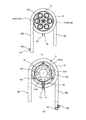
図1に示すように、この実施の形態に係る製氷装置1は、製氷筒体に収容した製氷水を凍らせて氷片を形成する断熱構造の製氷部10と、製氷部10により形成された氷片を簀の子上に貯留する断熱構造の貯氷部20とからなる。
As shown in FIG. 1, an
貯氷部20は、有底円筒状の内筒21と外筒22との間に断熱心材として硬質プラスチックフォームの原液を注入して発泡成形した断熱材23により断熱筐体として形成され、上端開口が断熱構造の蓋体30により閉塞されている。
The
この貯氷部20の底部における中心部には、製氷部10が貫通する開口が設けられ、この開口を介して製氷部10の上端部が貯氷部20の内部に臨むように構成されている。尚、貯氷部20の断熱材23は、後述する製氷部10を貯氷部20の底部を貫通させたうえで硬質プラスチックフォームの原液を注入して発泡成形することによって形成されるものである。また、製氷部10と貯氷部20の結合部には適宜Oリングなどのパッキングが装着されている。
An opening through which the
製氷部10は、図1の(b)に示すように、上端部が貯氷部20の内部に臨む製氷筒体11と、この製氷筒体11の外周面に巻回されたパイプ状の蒸発器12と、製氷筒体11の上端部に固着されたアイスブレーカー13と、製氷筒体11の下端部に固着されたジョイント14と、製氷筒体11の外周面に巻回された蒸発器12の周囲を囲繞する断熱材(発泡型により発泡成形)15とを備え、断熱材15により断熱構造体として形成されている。
As shown in FIG. 1B, the
製氷筒体11は、図3及び図4にも示すように、金属製(例えば、ステンレス製)の円柱体であって、リボルバー型拳銃の回転式弾倉のような形状を有する。すなわち、製氷筒体11は、円柱体の周縁に沿って複数の製氷室111,111・・・が相互に所定の間隔をおいて形成されてなるものであり、この例では60度の間隔をおいて6個の製氷室111,111・・・が設けられている。
As shown in FIGS. 3 and 4, the
それぞれの製氷室111は、横断面円形であって製氷筒体11に上下方向に延在する穴として形成され、その上端に製氷室111と同様横断面円形の吐出口111aを有している。また、それぞれの製氷室111は、下端に製氷筒体11よりも一回り小さい円形の窪み112の周囲を形成する周壁113の肉により横断面円形の一部が閉塞された半円状の導入口111bを有している。
Each
そして、製氷室111は、図5及び図6の断面図に示すように、少なくともパイプ状の蒸発器12が巻回された製氷領域IMKが、下部側から上部側に向かうに従って断面積が漸増するテーパー状部分として形成されている。
As shown in the sectional views of FIGS. 5 and 6, the
この場合、テーパーの勾配は、水が氷に変化するときの体積膨張(1.09倍)に合わせて定められている。より詳細には、製氷室11のテーパー状部分(製氷領域IMK)は、該テーパー状部分の下端の断面積に対する該下端以外の断面積の比が1より大きく1.09以下となる態様でテーパーの勾配が定められている。
In this case, the taper gradient is determined in accordance with the volume expansion (1.09 times) when water changes to ice. More specifically, the tapered portion (ice-making region IMK) of the
また、製氷領域IMKの下端とその下部域との境界箇所には製氷領域IMKの下端の断面積がその下部域の断面積に対して大きくなることで下部段差111c(図6参照)が設けられている。
Further, a
更に、製氷領域IMKの上端とその上方域との境界箇所にはその上方域の断面積が製氷領域IMKの上端の断面積に対して大きくなることで上部段差111d(図6参照)が設けられている。
Furthermore, an
また、製氷筒体11の上端における中心部には、ねじ穴114(図3参照)が形成されている。このねじ穴114は、製氷筒体11の中心に位置し、6個の製氷室111のそれぞれの中心軸がねじ穴114の中心軸から同一半径上に位置している。
Further, a screw hole 114 (see FIG. 3) is formed at the center of the upper end of the
また更に、製氷筒体11の下端の窪み112の中心部には逆円錐状の突起115が形成されている。この窪み112の周囲を形成する周壁113には、温度センサーS1が装着される穴(不図示)が形成されるとともにジョイント14をねじ止めするねじ穴116が形成されている。
Furthermore, an inverted
パイプ状の蒸発器12は、製氷筒体11の中間部位、すなわち、製氷体11に形成された製氷室111における製氷水が流動する下部域よりも上方の製氷領域IMK(図5参照)に対応する部位の外周面に3〜4ターン巻回されてなる。蒸発器12は、入口パイプ121に液冷媒、すなわち、冷凍サイクルを構成する圧縮機の運転により圧縮された高温高圧のガス冷媒を凝縮器により冷却して高温高圧の液冷媒とするととともに膨張機構により一定の圧力とされた液冷媒が供給され、かつこの液冷媒が製氷筒体11の外周面に巻回された蒸発器12を通過する際に製氷筒体11から熱を奪って蒸発した後のガス冷媒が蒸発器12の出口パイプ122を介して圧縮機に戻されるように構成されている。
The pipe-shaped
冷凍サイクルは、製氷筒体11における蒸発器12が巻回された部位(つまり、製氷室111の製氷範囲IMK)を所定の温度(例えば、零下10度)となるように冷却した後、製氷筒体11が所定の温度を維持するように運転制御される。
In the refrigeration cycle, a portion of the
尚、出口パイプ122にはガス冷媒の温度を検出する温度センサーS2が断面S字状の取付金具123を介して取付けられている。この温度センサーS2は、蒸発器12の出口温度を検出して圧縮機の運転効率を高める周知のものである。
A temperature sensor S2 for detecting the temperature of the gas refrigerant is attached to the
アイスブレーカー13は金属製のもので、図5及び図6に示すように、ねじ部131と氷片形成部132とからなる。ねじ部131は、製氷筒体11の上端に形成されたねじ穴114に対応する雄ねじが形成されてなり、このねじ部131をねじ穴114に螺合させることによりアイスブレーカー13が製氷筒体11に固着される。
The
氷片形成部132は、ねじ部131よりも一回り大きく、かつ製氷筒体11に設けられた6個の製氷室111の穴と重なり合うことのない大きさであって、円筒部132aと傾斜面部132bとからなる。円筒部は、製氷筒体11の上端から所定寸法だけ上方に延在するものである。傾斜面部132bは、円筒部132aから製氷筒体11に設けられた6個の製氷室111の穴の軸線をそれぞれ横切るように放射状に拡がった傾斜面を有する六面体のものである。
The ice
ここで、アイスブレーカー13を製氷筒体11に固着する際、傾斜面部132bにおける六面体のそれぞれの傾斜面が製氷筒体11に設けられた6個の製氷室111の穴にそれぞれ対峙するように位置決めされる。また、アイスブレーカー13の氷片形成部132には、上下方向に穿孔されるともに底部に横穴が形成された水抜き穴133が形成されている。
Here, when the
ジョイント14は、金属製のもので、図5に示すように、製氷水が供給される漏斗状の製氷水導入部141と、製氷水導入部141の上部に連接された円筒状の結合部142と、製氷水導入部141の上端から外方に延在する鍔部143とからなる。
As shown in FIG. 5, the joint 14 is made of metal, and as shown in FIG. 5, a funnel-shaped ice-making
円筒状の結合部142は、製氷筒体11の下端に形成した窪み112に嵌合する大きさに形成されるとともに外周面にOリングPの保持溝が形成されている。鍔部143は、製氷筒体11の径よりも一回り大きな径を有し、製氷筒体11の下端の周壁113に設けた温度センサーS1が装着される穴(不図示)及びねじ穴116に対応してねじの挿通穴143aが設けられている。
The
製氷水導入部141は、円錐状の底部に製氷水導入管141aが形成されてなり、この製氷水導入管141aに製氷水の供給パイプ、例えば、製氷水としての水道水を貯留する貯留タンク(シスターン)からの供給パイプが接続される。
The ice making
ここで、この製氷装置1は、製氷装置1自身では水位調節機構を有していない一方、良質の氷片を連続して製氷するには製氷筒体11(製氷室111)内の水位を製氷筒体11に巻回された蒸発器12の高さ位置の適切な水位に保つ必要がある。この場合、適切な水位とは製氷筒体11の製氷室111における製氷領域IMK(図5、図6参照)の上限の水位である。
Here, the
そこで、水位調節機構を有するシスターンを製氷装置1と横並びに設置して製氷筒体11(製氷室111)内の水位をシスターンの水位と同一となるようにすれば、製氷筒体11(製氷室111)内の水位を製氷筒体11に巻回された蒸発器12の高さ位置の適切な水位に保つことができる。尚、ジョイント14は金属製に限るものではない。
Therefore, if a cistern having a water level adjusting mechanism is installed side by side with the
断熱材15は、製氷筒体11に対して蒸発器12、アイスブレーカー13及びジョイント14を組付けて形成したアセンブリー部品を発泡型の内部に収容した状態で、発泡型に硬質プラスチックフォームの原液を注入して発泡成形することによりアセンブリー部品の周囲を囲繞して製氷部10を断熱構造体とするものである。
The
尚、製氷筒体11の下部の外周面に巻回された板状のヒーター16(図3及び図4参照)は、ジョイント14における製氷水導入部141に供給された製氷水が凍結するのを防止するものである。
The plate-like heater 16 (see FIGS. 3 and 4) wound around the outer peripheral surface of the lower part of the
製氷装置1の運転により貯氷部20が満杯となって製氷装置1の運転を停止した際、製氷筒体11の製氷室111内の氷によりジョイント14における製氷水導入部141内に滞留した製氷水が凍結してしまうおそれがある。
When the
そこで、製氷筒体11の下端に形成された周壁113に装着された温度センサーS1からの検出出力に基づいてヒーター16に通電し、ジョイント14における製氷水導入部141内に滞留した製氷水が凍結することがないようにされている。
Therefore, the
ヒーター16は絶縁体により被覆されており、その両端には端子T1,T2が固着されている。また、ヒーター16は弾性を有するばね材により馬蹄形状に形成するのが良く、この場合には製氷筒体11の外周面にヒーター16を密着させることができる。
The
製氷部10の組立てについて以下に説明する。すなわち、製氷部10の組立ては、製氷筒体11の上端に形成したねじ穴114にアイスブレーカー13のねじ部131を螺合させて製氷筒体11にアイスブレーカー13を固着する。
The assembly of the
この場合、アイスブレーカー13の傾斜面部132bにおける六面体のそれぞれの傾斜面が製氷筒体11に設けられた6個の製氷室111の穴にそれぞれ対峙するように位置決めして固着する。
In this case, the hexahedron inclined surfaces of the
次いで、製氷筒体11の下端に形成した窪み112にジョイント14の円筒状の結合部142を嵌め込んでジョイント14を取付けるのであるが、この場合、製氷筒体11を倒置した状態で網目状の水フィルタ17(図4参照)を窪み112の底部に設置したうえで、当該窪み112にジョイント14の円筒状の結合部142を嵌め込む。これにより水フィルタ17は結合部142と窪み112の底部との間に挟持される。
Next, the joint 14 is attached by fitting the
その後、ジョイント14の鍔部143に設けた挿通穴143aを介して製氷筒体11の周壁113に設けたねじ穴116にねじを螺合させて製氷筒体11にジョイント14を固着する。そして、端子T1,T2付きのヒーター16を製氷筒体11の外周面に装着する。この場合、ヒーター16が弾性を有する馬蹄形状に形成されている場合には、ヒーター16の両端が離隔するように広げて製氷筒体11の外周面に装着したうえでヒーター16から手を離すと、ヒーター16の両端が接近してヒーター16が製氷筒体11の外周に密着する。
Thereafter, a screw is screwed into a
次いで、製氷筒体11の外周面にパイプ状の蒸発器12を巻回する。この場合、蒸発器12は、製氷筒体11に巻回される蒸発管路と入口パイプ121及び出口パイプ122に分割され、蒸発管路を製氷筒体11に巻回した後、その両端に入口パイプ121及び出口パイプ122をそれぞれ接続する。
Next, a pipe-shaped
尚、蒸発管路と入口パイプ121及び出口パイプ122とに分割することなく、一本の長いパイプを螺旋状に3〜4ターンに巻いたうえで螺旋状の接線方向に延在するパイプを鉛直方向に折り曲げて入口パイプ121及び出口パイプ122を形成することもでき、また、パイプ状の蒸発器12を直接製氷筒体11に巻き付けるのではなく、予め所定形状(3〜4ターンの螺旋状部に入口パイプ,出口パイプを接続したもの)に形成しておき、この蒸発器12を製氷筒体11に半田接合して取り付けることもできる。
In addition, without dividing the evaporation pipe and the
上述したように、製氷筒体11に対してヒーター16、蒸発器12、アイスブレーカー13及びジョイント14を取り付けて形成したアセンブリー部品を発泡型の内部に収納して断熱材15を発泡成形する。この場合、発泡型からは製氷筒体11の上部(頭部)、蒸発器12の入口パイプ121、出口パイプ122、ヒーター16の端子T1,T2及び温度センサーS1のコネクタ部が露出するように、アセンブリー部品を発泡型の内部に収容した状態で発泡型に硬質プラスチックフォームの原液を注入して発泡成形することによりアセンブリー部品の周囲を断熱材15で囲繞した製氷部10が作製される。尚、断熱材15は、上部(頭部)15aが胴部15bに対して一回り小さく形成されてなるものである。
As described above, the assembly part formed by attaching the
このように作製された製氷部10を、貯氷部20を構成する有底円筒状の内筒21と外筒22のそれぞれの底部に組み付ける。この場合、有底円筒状の内筒21の底部の開口は貯氷部10における製氷筒体11の上部(頭部)が貫通可能な大きさに形成され、有底円筒状の外筒22の底部の開口は貯氷部10における断熱材15の頭部15aが貫通可能な大きさに形成されている。
The
従って、製氷部10を貯氷部20の底部に組み付けた際、製氷部10における断熱材15の胴部15bの段差部が貯氷部20の外筒22の底部に形成した開口の周縁に当接して位置決めされる。この状態で、貯氷部20の内筒21と外筒22との間に硬質プラスチックフォームの原液を注入して発泡成形することによって、貯氷部20が断熱構造体として形成されるとともに製氷部10と貯氷部20とが強固に結合された製氷装置1が作製される。
Therefore, when the
ここで、製氷部10を貯氷部20の底部に組み付ける際、製氷部10における製氷筒体11の上部側外周部にOリングP1(図1の(b)参照)が装着されるものであり、これにより貯氷部20の内筒21の開口と製氷部10における製氷筒体11の頭部との間がシールされる。
Here, when assembling the
尚、製氷部10の貯氷部20への組み付けは、前述した例に限らず、製氷部10と貯氷部20とをそれぞれ断熱構造体として別個に作製したうえで製氷部10を貯氷部20底部に設けた開口に嵌合させて組み付けることもできるものである。
The assembly of the
さて、製氷装置1を運転する際、不図示のシスターンからジョイント14を介して製氷筒体11の製氷室111に製氷水が供給される。すなわち、シスターンからジョイント14の製氷水導入管141aを介して製氷筒体11の下端の窪み112に供給された製氷水は、製氷室111の下端に形成された半円状の導入口111bを通ってそれぞれの製氷室111内に流入する。
Now, when the
この場合、製氷筒体11の下端に設けた窪み112内には製氷水が貯留されるが、その中心部には逆円錐状の突起115が形成されており、窪み112内は製氷水により満たされるので、気泡が生じることがない。
In this case, ice making water is stored in the
そして、製氷室111内に貯留された製氷水の水位は、少なくともパイプ状の蒸発器12が巻回された製氷領域IMK(図5参照)の上限位置となる。つまり、この製氷装置1自体は水位調節機能を備えておらず、製氷水を所定水位の範囲で貯留する水位調節機構を有するシスターンを、製氷装置1と横並びに設置して製氷室111内の水位をシスターンの水位と同一となるように構成されているので、製氷室111内に貯留される製氷水の水位が製氷領域IMK(図5参照)の上限位置となるようにシスターンの設置位置が定められている。これにより、シスターンから製氷室111内に供給された製氷水は、製氷領域IMK(図5参照)における上限位置まで貯留される。
The water level of the ice making water stored in the
かかる状態で冷凍サイクルの圧縮機を運転して高温高圧の液冷媒を供給し、蒸発器12に液冷媒を供給すると、この液冷媒が製氷筒体11の外周面に巻回された蒸発器12を通過する過程において製氷筒体11から熱を奪って蒸発してガス冷媒となる際に製氷筒体11を冷却する。
In this state, when the compressor of the refrigeration cycle is operated to supply the high-temperature and high-pressure liquid refrigerant and the liquid refrigerant is supplied to the
この場合、蒸発器12による冷却は、製氷筒体11が所定の温度(例えば、零下10度)となるように定められており、製氷室111に貯留された製氷水のうち、製氷領域IMK(図5参照)の製氷水の温度が摂氏0度以下に冷却されると製氷室111の内壁から中心に向かって徐々に凍って氷となる。
In this case, the cooling by the
このように製氷水が氷になるときの体積膨張により製氷室111の内壁は圧力を受けるが、製氷室111を形成する製氷筒体11が金属製(例えば、ステンレス製)であることから変形することはなく、逆に、製氷室111の内壁からの反作用により氷に圧力が加わる。
Thus, although the inner wall of the
ここで、製氷室111の製氷領域IMKにおいては下部側から上部側に向かうに従って断面積が漸増するテーパー状に形成されているので、氷に加わった圧力の一部は氷を上向きに押し上げる推進力となる。
Here, in the ice making region IMK of the
また、製氷領域IMKの下端とその下部域との境界箇所には製氷領域IMKの下端の断面積がその下部域の断面積に対して大きくなる下部段差111cが設けられているので、製氷領域IMKの下端で形成された氷が下部段差111cの水平面に引っ掛かり、当該当下部段差111cからの反作用で氷を上向きに押し上げる推進力となる。
In addition, since the
このように製氷室111における製氷領域IMKで製氷された氷には、その製氷が進行するにつれて上向きに押し上げられる推進力が作用して製氷室111内を上方に押し上げられる。
In this way, the ice made in the ice making region IMK in the
上方に押し上げられた氷の後にはシスターンから製氷室111の下部域を通って供給された製氷水が侵入して製氷室111の製氷領域IMKにおいては連続して製氷が進行するので、製氷室111の製氷領域IMKにおいて製氷された氷は連続して上方に押し上げられ、あたかも氷柱が逆方向に成長するかのごとき態様で製氷室111の上方に向けて円柱状の氷塊が上方へ進行してゆく。
After the ice pushed upward, ice making water supplied from the cistern through the lower area of the
尚、製氷室111における製氷領域IMKは、製氷領域IMKに供給する製氷水が通る(流動する)下部域を残しているので、製氷室111への製氷水の供給通路が氷結して製氷水が供給されなくなることはない。
The ice making area IMK in the
製氷室111の製氷領域IMKから製氷室111内を上方へ進行していく氷塊は、製氷室111の製氷領域IMKの上端とその上方域との境界箇所にはその上方域の断面積が製氷領域IMKの上端の断面積に対して大きくなる上部段差111dが設けられている。
The ice mass that progresses upward from the ice making region IMK of the
つまり、製氷領域IMKの断面積に対してその上方域の断面積が大きく形成されているので、製氷室111内を上方へ進行する氷塊は製氷室111の内壁による抵抗を受けることがない。
That is, since the cross-sectional area of the upper region is formed larger than the cross-sectional area of the ice making region IMK, the ice mass that travels upward in the
また、製氷室111での連続した製氷により製氷室111内を上方へ進行する円柱状の氷塊の上端が製氷室111の吐出口111aから出てからアイスブレーカー13における傾斜面部132bに到達するまでの行程においてはその氷塊の進行を妨げるものがないので、円柱状の氷塊は、アイスブレーカー13における円筒部132aに沿って上方(鉛直方向)へ進行する。
Further, the upper end of the columnar ice block that progresses upward in the
そして、上方(鉛直方向)へ進行する氷塊の上端がアイスブレーカー13の傾斜面部132bに接触すると鉛直方向に延在する氷塊の進行方向が方向転換される。この場合、製氷室111内の氷塊は製氷室111の内壁に保持されて鉛直姿勢が維持される一方、製氷室111の吐出口111aから出た氷塊の周縁を保持する部材がないことから鉛直姿勢を維持することができなくなる。
And if the upper end of the ice block which progresses upward (vertical direction) contacts the
このため、上方(鉛直方向)へ進行する氷塊の上端がアイスブレーカー13の傾斜面部132bに接触すると鉛直方向に延在する氷塊の進行方向が方向転換されると、製氷室111の吐出口111aから出た氷塊は製氷室111の縁部を支点として屈曲して破壊応力を超えると折れて氷片となる。
For this reason, when the upper end of the ice mass traveling upward (vertical direction) comes into contact with the
このようにして形成された氷片は、貯氷部20内に落下して貯氷される。貯氷部20に氷片が貯留されて満杯となると、冷凍サイクルの圧縮機の運転を停止して製氷装置1は待機状態となる。尚、図示は省略したが、貯氷部20内には貯留された氷片を攪拌して大きな氷塊となるのを抑制する攪拌手段が設けられているものである。
The ice pieces formed in this manner fall into the
かかる待機状態において製氷室111の製氷領域IMKには氷が残っており、かつ製氷室111における製氷領域IMKの下部域の製氷水が流動せずに滞留していることから氷結するおそれがある。
In this standby state, ice remains in the ice making area IMK of the
そこで、製氷筒体11の下端に設けた温度センサーS1により製氷筒体11の下部の冷却温度を監視し、当該温度センサーS1の出力に基づいて製氷室111の下部域に滞留した製氷水が氷結する以前にヒーター16に通電する。
Accordingly, the temperature sensor S1 provided at the lower end of the
これにより製氷室111の下部域に滞留した製氷水が氷結して製氷装置1により製氷を再開する際に製氷室111に製氷水が供給されなくことを防止することができる。
As a result, it is possible to prevent the ice making water staying in the lower area of the
また、この種の製氷装置1が設置される環境温度(仕様)は、約1℃〜40℃の範囲に定められているが、冬季の夜間(特に、寒冷地)には室内であっても0℃以下になることがあり、シスターンから製氷装置1までの供給管路について破裂防止対策を施したとしても製氷筒体11における製氷室111の下部域に滞留した製氷水が氷結するおそがあり、この場合には外気温度を検出する温度センサー(不図示)の検出出力に基づいてヒーター16に通電するようにすることもできる。
In addition, the environmental temperature (specification) in which this type of
また、ヒーター16への通電により製氷水を加熱することによって製氷水の温度を高めることができ、これによって高温の水がより低温の水よりも短時間で凍る現象、すなわち、ムペンバ効果を得ることができる。
Further, the temperature of the ice-making water can be increased by heating the ice-making water by energizing the
実施の形態では、製氷室111は、断面形状が円形のものについて説明したが、断面形状が四角などの多角形とすることができるものであり、実施の形態の形状に限定されるものではない。
In the embodiment, the
また、実施の形態では、貯氷部20が蓋体30を備えたものについて説明したが、蓋体30を持たない密閉構造とするとともに貯氷部20の側壁に氷片投出口(不図示)を設け、かつ氷片投出口を開閉する氷搬出扉と、この氷搬出扉を開閉制御するソレノイドと、このソレノイドに駆動指令を与える開閉ボタンとを設け、開閉ボタンの操作によりソレノイドを駆動して氷搬出扉を開閉して氷を搬出するように構成することもできる。この場合、氷搬出扉を開放する際、貯氷部20に設けた攪拌手段を同時に作動させて貯氷部20に貯氷された氷片を攪拌すると氷片投出口からの氷の搬出を確実なものとすることができる。
Moreover, although the
更に、実施の形態では、製氷筒体11の外周面にヒーター16を装着したものについて説明したが、このヒーター16に代えて蒸発器12を凝縮器として利用、つまり、蒸発器12を通過する冷媒を逆流させることによって凝縮器として機能させることによりヒーター16を削除することもできるものである。
Furthermore, in the embodiment, the
上述したように、この実施の形態に係る製氷装置1においては、圧縮機と凝縮器と膨張機構と蒸発器12とからなる冷凍サイクルを有するものであって、上下方向に直線的に延在する穴の上端に吐出口111aを有するとともに下部に製氷水の導入口111bを有する製氷室111が形成された製氷筒体11と、導入口111bを介して製氷室111内に供給された製氷水を凍らせるように製氷筒体11を冷却する蒸発器12と、製氷筒体11における製氷室111の上方域に位置して当該製氷室111の軸線を横切る氷片形成部132を有するアイスブレーカー13とを備えている。そして、製氷筒体11における製氷室111は、下部側から上部側に向かうに従って断面積が漸増するテーパー状部分(製氷領域IMK)を有してなり、蒸発器12による冷却により製氷水が氷に変化するときの体積膨張による圧力で氷を押し上げる推進力として製氷室111内を上方に進行する柱状の氷塊を形成し、製氷の進行により製氷室111の吐出口111aから押し出された柱状の氷塊の進行方向をアイスブレーカー13の氷片形成部132に当接させて柱状の氷塊が破壊応力を超えて折れる態様で方向転換させて氷片を形成するものである。これにより、製氷水が氷になるときの体積膨張による圧力で氷を所定方向に進行させる推進力として駆動源レスによりチップ状の氷片を形成することができ、オーガ式製氷機のように、製氷筒内壁面に着氷した薄氷をフレーク状に切削して押し上げるオーガを駆動する駆動モータを必要とせずにチップ状の氷片を形成することが可能となるという効果を奏する。
As described above, the
以上、本発明の実施の形態について説明したが、本発明はこれに限定されるものではなく、種々の変更を行うことができる。 As mentioned above, although embodiment of this invention was described, this invention is not limited to this, A various change can be performed.
上述した実施の形態では、製氷室111に対する製氷水の供給をシスターンから行っていたが、本発明においては、図7に示すように、製氷筒体11の下部に、例えばインジェクタ等に代表される定量ポンプにより構成される供給手段40を設けてもよい。この供給手段40は、製氷水を定量的に加圧して製氷室111に供給するものである。このような供給手段40を通じて製氷水を供給することにより、製氷室111に対して安定的に製氷水を供給することができる。また製氷装置の全体の小型化を図ることができる。
In the embodiment described above, the ice making water is supplied to the
1…製氷装置、10…製氷部、11…製氷筒体、12…蒸発器、13…アイスブレーカー、14…ジョイント、15…断熱材、16…ヒーター、20…貯氷部、111…製氷室、111a…吐出口、111b…導入口、112…窪み、115…突起、131…ねじ部、132…氷片形成部、132a…円筒部、132b…傾斜面部。
DESCRIPTION OF
Claims (9)
上下方向に直線的に延在する穴の上端に吐出口を有するとともに下部に製氷水の導入口を有する製氷室が形成された製氷筒体と、
前記導入口を介して製氷室内に供給された製氷水を凍らせるように前記製氷筒体を冷却する蒸発器及び前記製氷筒体における製氷室の上方域に位置して当該製氷室の軸線を横切る氷片形成部を有するアイスブレーカーと
を備え、
前記製氷筒体における製氷室は、下部側から上部側に向かうに従って断面積が漸増するテーパー状部分を有してなり、前記蒸発器による冷却により製氷水が氷に変化するときの体積膨張による圧力を、前記氷を押し上げる推進力として前記製氷室内を上方に進行する柱状の氷塊を形成し、製氷の進行により製氷室の吐出口から押し出された柱状の氷塊の進行方向をアイスブレーカーの氷片形成部に当接させて柱状の氷塊が破壊応力を超えて折れる態様で方向転換させて氷片を形成することを特徴とする製氷装置。An ice making device having a refrigeration cycle comprising a compressor, a condenser, an expansion mechanism, and an evaporator,
An ice making cylinder in which an ice making chamber having a discharge port at the upper end of a hole extending linearly in the vertical direction and having an inlet for making ice water at the bottom is formed;
An evaporator that cools the ice-making cylinder so as to freeze ice-making water supplied to the ice-making chamber through the inlet, and an upper area of the ice-making chamber in the ice-making cylinder that crosses the axis of the ice making chamber An ice breaker having an ice piece forming part,
The ice making chamber in the ice making cylinder has a tapered portion whose cross-sectional area gradually increases from the lower side toward the upper side, and pressure due to volume expansion when the ice making water changes to ice by cooling by the evaporator As a driving force that pushes up the ice, a columnar ice mass that travels upward in the ice making chamber is formed, and the traveling direction of the columnar ice mass that is pushed out from the discharge port of the ice making chamber by the progress of ice making is formed as an ice piece of an ice breaker The ice making device is characterized in that the ice pieces are formed by changing the direction in such a manner that the columnar ice blocks are bent in excess of the breaking stress by abutting the portion.
Applications Claiming Priority (3)
| Application Number | Priority Date | Filing Date | Title |
|---|---|---|---|
| JP2014150960 | 2014-07-24 | ||
| JP2014150960 | 2014-07-24 | ||
| PCT/JP2015/070852 WO2016013584A1 (en) | 2014-07-24 | 2015-07-22 | Ice-making device |
Related Child Applications (1)
| Application Number | Title | Priority Date | Filing Date |
|---|---|---|---|
| JP2017209961A Division JP6504229B2 (en) | 2014-07-24 | 2017-10-31 | Ice maker |
Publications (2)
| Publication Number | Publication Date |
|---|---|
| JPWO2016013584A1 JPWO2016013584A1 (en) | 2017-04-27 |
| JP6237904B2 true JP6237904B2 (en) | 2017-11-29 |
Family
ID=55163108
Family Applications (2)
| Application Number | Title | Priority Date | Filing Date |
|---|---|---|---|
| JP2016535953A Active JP6237904B2 (en) | 2014-07-24 | 2015-07-22 | Ice making equipment |
| JP2017209961A Active JP6504229B2 (en) | 2014-07-24 | 2017-10-31 | Ice maker |
Family Applications After (1)
| Application Number | Title | Priority Date | Filing Date |
|---|---|---|---|
| JP2017209961A Active JP6504229B2 (en) | 2014-07-24 | 2017-10-31 | Ice maker |
Country Status (3)
| Country | Link |
|---|---|
| JP (2) | JP6237904B2 (en) |
| CN (1) | CN106461303B (en) |
| WO (1) | WO2016013584A1 (en) |
Cited By (1)
| Publication number | Priority date | Publication date | Assignee | Title |
|---|---|---|---|---|
| KR20190096531A (en) * | 2018-02-09 | 2019-08-20 | 이현옥 | Improved compressing structure of auger type ice maker |
Families Citing this family (4)
| Publication number | Priority date | Publication date | Assignee | Title |
|---|---|---|---|---|
| KR101868427B1 (en) * | 2016-12-13 | 2018-06-18 | 최현선 | Apparatus for Manufacturing Ice Syrup |
| CN111141076B (en) * | 2019-12-19 | 2022-04-19 | 佛山市南海区平洲技能五金机械厂 | Ice making barrel, seawater ice making machine, seawater ice making system and ice making method |
| KR102233469B1 (en) * | 2020-10-26 | 2021-03-29 | 이진구 | Evaporator for ice-making and ice-making device with the same |
| CN112696850A (en) * | 2021-01-05 | 2021-04-23 | 昆明天策节能科技有限公司 | Totally enclosed ice making system |
Family Cites Families (12)
| Publication number | Priority date | Publication date | Assignee | Title |
|---|---|---|---|---|
| US2747379A (en) * | 1952-04-09 | 1956-05-29 | Flakice Corp | Laminae freezer |
| DE921872C (en) * | 1953-03-14 | 1954-12-30 | Ziemann A G A | Method and device for making ice |
| DE929255C (en) * | 1953-05-22 | 1955-06-23 | Ziemann A G A | Method and device for producing ice bars |
| US3908395A (en) * | 1973-02-09 | 1975-09-30 | Hobbs Alan J | Device for dispensing ice |
| JPS6128993Y2 (en) * | 1981-03-13 | 1986-08-27 | ||
| JPS58142176A (en) * | 1982-02-18 | 1983-08-23 | 石川島播磨重工業株式会社 | Device for manufacturing ice grain |
| JP2559208Y2 (en) * | 1991-09-09 | 1998-01-14 | ホシザキ電機株式会社 | Ice making structure of automatic ice machine for block ice |
| JP3654523B2 (en) * | 2002-03-08 | 2005-06-02 | アイスマン株式会社 | Ice making machine and ice making method |
| JP2005037079A (en) * | 2003-07-16 | 2005-02-10 | Hoshizaki Electric Co Ltd | Pump motor for ice-making machine |
| ITMI20060250A1 (en) * | 2006-02-10 | 2007-08-11 | Frimont Spa | ICE MAKING MACHINE |
| JP2010276285A (en) * | 2009-05-28 | 2010-12-09 | Hoshizaki Electric Co Ltd | Ice making machine |
| EP2549209B1 (en) * | 2011-07-20 | 2019-01-02 | Brema Group S.p.A. | Extruded ice making machine |
-
2015
- 2015-07-22 WO PCT/JP2015/070852 patent/WO2016013584A1/en active Application Filing
- 2015-07-22 CN CN201580028780.3A patent/CN106461303B/en active Active
- 2015-07-22 JP JP2016535953A patent/JP6237904B2/en active Active
-
2017
- 2017-10-31 JP JP2017209961A patent/JP6504229B2/en active Active
Cited By (2)
| Publication number | Priority date | Publication date | Assignee | Title |
|---|---|---|---|---|
| KR20190096531A (en) * | 2018-02-09 | 2019-08-20 | 이현옥 | Improved compressing structure of auger type ice maker |
| KR102155224B1 (en) * | 2018-02-09 | 2020-09-11 | 이현옥 | Improved compressing structure of auger type ice maker |
Also Published As
| Publication number | Publication date |
|---|---|
| JPWO2016013584A1 (en) | 2017-04-27 |
| CN106461303B (en) | 2019-05-07 |
| JP6504229B2 (en) | 2019-04-24 |
| WO2016013584A1 (en) | 2016-01-28 |
| CN106461303A (en) | 2017-02-22 |
| JP2018031581A (en) | 2018-03-01 |
Similar Documents
| Publication | Publication Date | Title |
|---|---|---|
| JP2018031581A (en) | Ice maker | |
| US11976877B2 (en) | Method for controlling water purifier | |
| US20080156000A1 (en) | Ice maker and method for making ice | |
| KR101916878B1 (en) | Cold Water Generating Tank And Water Cooler Having the Same | |
| US20180283758A1 (en) | Method and apparatus for making nugget ice in a refrigerator | |
| EP2787310B1 (en) | Beverage cooling device and beverage supply system using cooling device | |
| KR100938642B1 (en) | Evaporater in icing apparatus and method for manufacturing the same | |
| KR100772214B1 (en) | Manufacturing apparatus and method for transparent ice | |
| KR101026909B1 (en) | Ice making apparatus | |
| US20190360736A1 (en) | Ice making assemblies and methods for making clear ice | |
| WO2021047463A1 (en) | Evaporator assembly for ice-making apparatus | |
| KR101916879B1 (en) | Cold Water Generating Tank And Water Cooler Having the Same | |
| WO2024208352A1 (en) | Ice making module and electrical device | |
| KR20100110663A (en) | Apparatus for purifying water | |
| KR20140021947A (en) | Ice maker equipped with guide tube for refrigerant | |
| US2921443A (en) | Method of and machine for manufacturing ice cubes and crushed ice | |
| JPS6050247B2 (en) | Refrigeration equipment | |
| EP1906120A1 (en) | Household appliance for the supplying of cooled water or other beverage and relative operation method | |
| KR200475742Y1 (en) | Water Purifier and Hot/Cold Water Supplier in Capable of Making Various Shaped Ice | |
| CN209978450U (en) | Composite screw type ice making device | |
| KR102649978B1 (en) | Method for controlling water purifying apparatus | |
| KR101483028B1 (en) | Ice maker controlling method of refrigerator | |
| US6470701B2 (en) | Ice maker and method of making ice | |
| WO2022077347A1 (en) | Flow rate control method for an ice making assembly | |
| CN219735711U (en) | Refrigerator with a refrigerator body |
Legal Events
| Date | Code | Title | Description |
|---|---|---|---|
| A621 | Written request for application examination |
Free format text: JAPANESE INTERMEDIATE CODE: A621 Effective date: 20161208 |
|
| TRDD | Decision of grant or rejection written | ||
| A01 | Written decision to grant a patent or to grant a registration (utility model) |
Free format text: JAPANESE INTERMEDIATE CODE: A01 Effective date: 20171003 |
|
| A61 | First payment of annual fees (during grant procedure) |
Free format text: JAPANESE INTERMEDIATE CODE: A61 Effective date: 20171016 |
|
| R150 | Certificate of patent or registration of utility model |
Ref document number: 6237904 Country of ref document: JP Free format text: JAPANESE INTERMEDIATE CODE: R150 |
|
| R250 | Receipt of annual fees |
Free format text: JAPANESE INTERMEDIATE CODE: R250 |
|
| R250 | Receipt of annual fees |
Free format text: JAPANESE INTERMEDIATE CODE: R250 |
|
| R250 | Receipt of annual fees |
Free format text: JAPANESE INTERMEDIATE CODE: R250 |
|
| R250 | Receipt of annual fees |
Free format text: JAPANESE INTERMEDIATE CODE: R250 |