JP6237582B2 - Gas-liquid separator and fuel cell system - Google Patents
Gas-liquid separator and fuel cell system Download PDFInfo
- Publication number
- JP6237582B2 JP6237582B2 JP2014231294A JP2014231294A JP6237582B2 JP 6237582 B2 JP6237582 B2 JP 6237582B2 JP 2014231294 A JP2014231294 A JP 2014231294A JP 2014231294 A JP2014231294 A JP 2014231294A JP 6237582 B2 JP6237582 B2 JP 6237582B2
- Authority
- JP
- Japan
- Prior art keywords
- gas
- liquid separator
- cover member
- wall
- wall portion
- Prior art date
- Legal status (The legal status is an assumption and is not a legal conclusion. Google has not performed a legal analysis and makes no representation as to the accuracy of the status listed.)
- Active
Links
Images


Classifications
-
- H—ELECTRICITY
- H01—ELECTRIC ELEMENTS
- H01M—PROCESSES OR MEANS, e.g. BATTERIES, FOR THE DIRECT CONVERSION OF CHEMICAL ENERGY INTO ELECTRICAL ENERGY
- H01M8/00—Fuel cells; Manufacture thereof
- H01M8/04—Auxiliary arrangements, e.g. for control of pressure or for circulation of fluids
- H01M8/04082—Arrangements for control of reactant parameters, e.g. pressure or concentration
- H01M8/04089—Arrangements for control of reactant parameters, e.g. pressure or concentration of gaseous reactants
- H01M8/04119—Arrangements for control of reactant parameters, e.g. pressure or concentration of gaseous reactants with simultaneous supply or evacuation of electrolyte; Humidifying or dehumidifying
- H01M8/04156—Arrangements for control of reactant parameters, e.g. pressure or concentration of gaseous reactants with simultaneous supply or evacuation of electrolyte; Humidifying or dehumidifying with product water removal
- H01M8/04164—Arrangements for control of reactant parameters, e.g. pressure or concentration of gaseous reactants with simultaneous supply or evacuation of electrolyte; Humidifying or dehumidifying with product water removal by condensers, gas-liquid separators or filters
-
- H—ELECTRICITY
- H01—ELECTRIC ELEMENTS
- H01M—PROCESSES OR MEANS, e.g. BATTERIES, FOR THE DIRECT CONVERSION OF CHEMICAL ENERGY INTO ELECTRICAL ENERGY
- H01M8/00—Fuel cells; Manufacture thereof
- H01M8/24—Grouping of fuel cells, e.g. stacking of fuel cells
- H01M8/2465—Details of groupings of fuel cells
-
- B—PERFORMING OPERATIONS; TRANSPORTING
- B01—PHYSICAL OR CHEMICAL PROCESSES OR APPARATUS IN GENERAL
- B01D—SEPARATION
- B01D45/00—Separating dispersed particles from gases or vapours by gravity, inertia, or centrifugal forces
- B01D45/04—Separating dispersed particles from gases or vapours by gravity, inertia, or centrifugal forces by utilising inertia
- B01D45/08—Separating dispersed particles from gases or vapours by gravity, inertia, or centrifugal forces by utilising inertia by impingement against baffle separators
-
- H—ELECTRICITY
- H01—ELECTRIC ELEMENTS
- H01M—PROCESSES OR MEANS, e.g. BATTERIES, FOR THE DIRECT CONVERSION OF CHEMICAL ENERGY INTO ELECTRICAL ENERGY
- H01M2250/00—Fuel cells for particular applications; Specific features of fuel cell system
- H01M2250/20—Fuel cells in motive systems, e.g. vehicle, ship, plane
-
- Y—GENERAL TAGGING OF NEW TECHNOLOGICAL DEVELOPMENTS; GENERAL TAGGING OF CROSS-SECTIONAL TECHNOLOGIES SPANNING OVER SEVERAL SECTIONS OF THE IPC; TECHNICAL SUBJECTS COVERED BY FORMER USPC CROSS-REFERENCE ART COLLECTIONS [XRACs] AND DIGESTS
- Y02—TECHNOLOGIES OR APPLICATIONS FOR MITIGATION OR ADAPTATION AGAINST CLIMATE CHANGE
- Y02E—REDUCTION OF GREENHOUSE GAS [GHG] EMISSIONS, RELATED TO ENERGY GENERATION, TRANSMISSION OR DISTRIBUTION
- Y02E60/00—Enabling technologies; Technologies with a potential or indirect contribution to GHG emissions mitigation
- Y02E60/30—Hydrogen technology
- Y02E60/50—Fuel cells
-
- Y—GENERAL TAGGING OF NEW TECHNOLOGICAL DEVELOPMENTS; GENERAL TAGGING OF CROSS-SECTIONAL TECHNOLOGIES SPANNING OVER SEVERAL SECTIONS OF THE IPC; TECHNICAL SUBJECTS COVERED BY FORMER USPC CROSS-REFERENCE ART COLLECTIONS [XRACs] AND DIGESTS
- Y02—TECHNOLOGIES OR APPLICATIONS FOR MITIGATION OR ADAPTATION AGAINST CLIMATE CHANGE
- Y02T—CLIMATE CHANGE MITIGATION TECHNOLOGIES RELATED TO TRANSPORTATION
- Y02T90/00—Enabling technologies or technologies with a potential or indirect contribution to GHG emissions mitigation
- Y02T90/40—Application of hydrogen technology to transportation, e.g. using fuel cells
Description
本発明は、燃料電池から排出されたオフガスに含まれる水を分離して排出する気液分離器に関する。 The present invention relates to a gas-liquid separator that separates and discharges water contained in off-gas discharged from a fuel cell.
固体高分子型燃料電池等の燃料電池に用いられる電解質膜は、高湿潤状態において高い発電性能を発揮できるため、燃料電池に供給する反応ガスが加湿されることがある。また、反応ガスの利用率の向上と燃料電池内における水の滞留の抑制を目的として、燃料電池から排出されるオフガスから水を分離し、得られた反応ガスを再び燃料電池に供給する循環型の反応ガス供給機構が用いられることがある。このような反応ガス供給機構では、オフガスから水を分離するために気液分離器が用いられる。例えば、特許文献1の燃料電池システムでは、筒状の気液分離部と気液分離部の鉛直下方に位置する貯留部とを備え、気液分離部に流入したアノードオフガスから水を分離して貯留部に一時的に溜めると共に、水を分離後のオフガスを排出する気液分離器が用いられている。この気液分離器では、気液分離部を厚さ方向に貫通するオフガスの入口管と出口管とが用いられる。 Since an electrolyte membrane used in a fuel cell such as a polymer electrolyte fuel cell can exhibit high power generation performance in a highly humid state, a reaction gas supplied to the fuel cell may be humidified. In addition, for the purpose of improving the utilization rate of the reaction gas and suppressing the retention of water in the fuel cell, the circulation type that separates water from the off-gas discharged from the fuel cell and supplies the obtained reaction gas to the fuel cell again. The reaction gas supply mechanism may be used. In such a reaction gas supply mechanism, a gas-liquid separator is used to separate water from off-gas. For example, the fuel cell system of Patent Document 1 includes a cylindrical gas-liquid separation unit and a storage unit positioned vertically below the gas-liquid separation unit, and separates water from the anode offgas flowing into the gas-liquid separation unit. A gas-liquid separator that temporarily accumulates in a reservoir and discharges off-gas after separating water is used. In this gas-liquid separator, an off-gas inlet pipe and an outlet pipe penetrating the gas-liquid separator in the thickness direction are used.
しかしながら、特許文献1の燃料電池システムが車両等に搭載され、かかる車両が坂を走行する場合などにおいて気液分離器の姿勢が傾くと、貯留部に溜まった水がオフガスの出口管(排出口)に浸入するおそれがあった。このように、気液分離器におけるオフガスの排出口に水が浸入すると、オフガスに水が再度含まれ、かかるオフガスが循環されるために、オフガスからの水の分離効率が低下するという問題があった。このため、気液分離器におけるオフガスの排出口に、分離された水が浸入することを抑制可能な技術が望まれていた。 However, when the fuel cell system of Patent Document 1 is mounted on a vehicle or the like, and the vehicle is traveling on a slope, the water and liquid separators are inclined and the water accumulated in the storage portion is discharged from an off-gas outlet pipe (discharge port). ). As described above, when water enters the off-gas outlet of the gas-liquid separator, water is again included in the off-gas, and the off-gas is circulated, so that the efficiency of separating water from the off-gas is reduced. It was. For this reason, the technique which can suppress that the isolate | separated water permeates into the discharge port of the off gas in a gas-liquid separator was desired.
本発明は、上述の課題の少なくとも一部を解決するためになされたものであり、以下の形態として実現することが可能である。
本発明の一形態によれば、積層された複数の単セルを有するセルスタックと、前記セルスタックに対して前記複数の単セルの積層方向の外側に配置されているエンドプレートと、を有する燃料電池から排出されたオフガスに含まれる水を分離して排出する気液分離器が提供される。この気液分離器は、前記エンドプレートに形成され、前記エンドプレートにおける前記積層方向の端面のうちの前記セルスタックとは反対側の端面に開口し、前記気液分離器の一部を構成する気液分離器形成部と;前記気液分離器形成部の開口を覆って配置され、前記気液分離器の一部を構成するカバー部材と;を備え;前記気液分離器形成部は;前記オフガスの排出口が形成されており、前記オフガスの流路として機能すると共に前記オフガスから分離された水が溜まる貯留部の一部を形成する第1の内壁部であって、前記開口に接続して前記エンドプレートの厚さ方向に凹状に形成されている第1の内壁部と;前記気液分離器形成部から前記カバー部材に向かう第1の方向に沿って前記第1の内壁部から突出して前記排出口を囲む囲み部と;を有し;前記囲み部における前記第1の方向の端面は、前記気液分離器形成部全体における前記第1の方向の端面から前記第1の方向とは反対方向にオフセットされており;前記カバー部材は;前記カバー部材における前記気液分離器形成部と対向する面に形成された開口に接続して前記カバー部材の厚さ方向に凹状に形成されている第2の内壁部であって、前記第1の内壁部と前記積層方向に対向して配置されて、前記第1の内壁部と共に前記貯留部を形成する第2の内壁部と;前記貯留部に溜まった水を排出する排水流路であって、自身の端部に前記第2の内壁部の底面の近傍に配置されて前記貯留部の内側に露呈している排水口が形成された排水流路を、形成する排水流路形成部と;前記カバー部材の前記第2の内壁部に形成された斜面と;を有し;前記カバー部材の前記第2の内壁部は、前記排水口と繋がり;前記斜面は、前記第1の方向とは反対方向に沿って次第に下方に傾斜する。
本発明の他の形態によれば、積層された複数の単セルを有するセルスタックと、前記セルスタックに対して前記複数の単セルの積層方向の外側に配置されているエンドプレートと、を有する燃料電池から排出されたオフガスに含まれる水を分離して排出する気液分離器が提供される。この気液分離器は、前記エンドプレートに形成され、前記エンドプレートにおける前記積層方向の端面のうちの前記セルスタックとは反対側の端面に開口し、前記気液分離器の一部を構成する気液分離器形成部と;前記気液分離器形成部の開口を覆って配置され、前記気液分離器の一部を構成するカバー部材と;を備え;前記気液分離器形成部は;前記オフガスの排出口が形成され、前記オフガスの流路として機能すると共に前記オフガスから分離された水が溜まる貯留部の一部を形成する第1の内壁部であって、前記開口に接続して前記エンドプレートの厚さ方向に凹状に形成されている第1の内壁部と;前記気液分離器形成部から前記カバー部材に向かう第1の方向に沿って前記第1の内壁部から突出して前記排出口を囲む囲み部と;を有し;前記囲み部の外表面のうち、前記気液分離器が載置された状態において鉛直下方に位置する外表面は、前記貯留部の底面と略平行であり;前記カバー部材は;前記カバー部材における前記気液分離器形成部と対向する面に形成された開口に接続して前記カバー部材の厚さ方向に凹状に形成されている第2の内壁部であって、前記第1の内壁部と前記積層方向に対向して配置されて、前記第1の内壁部と共に前記貯留部を形成する第2の内壁部と;前記貯留部に溜まった水を排出する排水流路であって、自身の端部に前記第2の内壁部の底面の近傍に配置されて前記貯留部の内側に露呈している排水口が形成された排水流路を、形成する排水流路形成部と;前記カバー部材の前記第2の内壁部に形成された斜面と;を有し;前記カバー部材の前記第2の内壁部は、前記排水口と繋がり;前記斜面は、前記カバー部材から前記第1の方向とは反対方向に沿って次第に下方に傾斜する。
SUMMARY An advantage of some aspects of the invention is to solve at least a part of the problems described above, and the invention can be implemented as the following forms.
According to one aspect of the present invention, a fuel having a cell stack having a plurality of stacked single cells, and an end plate disposed outside the cell stack in the stacking direction of the plurality of single cells. There is provided a gas-liquid separator that separates and discharges water contained in off-gas discharged from a battery. The gas-liquid separator is formed on the end plate, and is open to an end surface of the end plate opposite to the cell stack in the stacking direction, and constitutes a part of the gas-liquid separator. A gas-liquid separator forming part; and a cover member that covers an opening of the gas-liquid separator forming part and constitutes a part of the gas-liquid separator; the gas-liquid separator forming part; The off-gas discharge port is formed, and serves as a flow path for the off-gas, and is a first inner wall portion that forms a part of a storage portion in which water separated from the off-gas accumulates, and is connected to the opening A first inner wall portion that is formed in a concave shape in the thickness direction of the end plate; and from the first inner wall portion along a first direction from the gas-liquid separator forming portion toward the cover member. An enclosure that protrudes and surrounds the outlet An end face in the first direction in the enclosure is offset from an end face in the first direction in the entire gas-liquid separator forming part in a direction opposite to the first direction; The cover member is a second inner wall portion formed in a concave shape in the thickness direction of the cover member by connecting to an opening formed on a surface of the cover member facing the gas-liquid separator forming portion. A second inner wall portion that is disposed opposite to the first inner wall portion in the stacking direction and forms the storage portion together with the first inner wall portion; and discharges water accumulated in the storage portion. Drainage that forms a drainage channel that is disposed in the vicinity of the bottom surface of the second inner wall portion at the end of the drainage channel and that has a drainage port exposed inside the storage portion. A flow path forming portion; formed on the second inner wall portion of the cover member Slope and; have; the second inner wall portion of said cover member, said drain outlet and connected; wherein the beveled surface, wherein the first direction is gradually inclined downward along the opposite direction.
According to another aspect of the present invention, it has a cell stack having a plurality of unit cells stacked, and an end plate disposed outside the cell stack in the stacking direction of the plurality of single cells. A gas-liquid separator that separates and discharges water contained in off-gas discharged from a fuel cell is provided. The gas-liquid separator is formed on the end plate, and is open to an end surface of the end plate opposite to the cell stack in the stacking direction, and constitutes a part of the gas-liquid separator. A gas-liquid separator forming part; and a cover member that covers an opening of the gas-liquid separator forming part and constitutes a part of the gas-liquid separator; the gas-liquid separator forming part; A first inner wall portion that forms a part of a storage portion in which a discharge port for the off gas is formed, functions as a flow path for the off gas, and stores water separated from the off gas, and is connected to the opening. A first inner wall portion formed in a concave shape in the thickness direction of the end plate; and protruding from the first inner wall portion along a first direction from the gas-liquid separator forming portion toward the cover member. An enclosing portion surrounding the discharge port; Of the outer surface of the enclosure, the outer surface located vertically below the gas-liquid separator is placed is substantially parallel to the bottom surface of the reservoir; the cover member is the cover A second inner wall portion connected to an opening formed on a surface of the member facing the gas-liquid separator forming portion and formed in a concave shape in the thickness direction of the cover member, wherein the first inner wall A second inner wall portion that is disposed in opposition to the laminating direction and forms the storage portion together with the first inner wall portion; and a drainage channel that discharges water accumulated in the storage portion, A drainage channel forming part for forming a drainage channel disposed at the end of the drain wall and disposed near the bottom surface of the second inner wall part and exposed to the inside of the storage part; A slope formed on the second inner wall of the cover member; and the cover Said second inner wall portion of the water outlet and connected; wherein the beveled surface is gradually inclined downward along the direction opposite to the first direction from the cover member.
(1)本発明の一形態によれば、積層された複数の単セルを有するセルスタックと、前記セルスタックに対して前記複数の単セルの積層方向の外側に配置されているエンドプレートと、を有する燃料電池から排出されたオフガスに含まれる水を分離して排出する気液分離器が提供される。この気液分離器は、前記エンドプレートに形成され、前記エンドプレートにおける前記積層方向の端面のうちの前記セルスタックとは反対側の端面に開口し、前記気液分離器の一部を構成する気液分離器形成部と;前記気液分離器形成部の開口を覆って配置され、前記気液分離器の一部を構成するカバー部材と;を備え、前記気液分離器形成部は、前記オフガスの排出口が形成されており、前記オフガスの流路として機能すると共に前記オフガスから分離された水が溜まる貯留部の一部を形成する第1の内壁部であって、前記開口に接続して前記エンドプレートの厚さ方向に凹状に形成されている第1の内壁部と;前記気液分離器形成部から前記カバー部材に向かう第1の方向に沿って前記第1の内壁部から突出して前記排出口を囲む囲み部と;を有し、前記囲み部における前記第1の方向の端面は、前記気液分離器形成部全体における前記第1の方向の端面から前記第1の方向とは反対方向にオフセットされている、気液分離器。この形態の気液分離器によれば、囲み部における第1の方向の端部は、気液分離器形成部全体における第1の方向の端面から第1の方向とは反対方向にオフセットされているので、カバー部材の底面から囲み部の第1の方向の端部までの距離を比較的長くできる。このため、カバー部材の底面に溜まった水が排出口に浸入することを抑制できる。したがって、気液分離器における水の分離効率の低下を抑制できる。 (1) According to one aspect of the present invention, a cell stack having a plurality of stacked single cells, an end plate disposed outside the cell stack in the stacking direction of the plurality of single cells, There is provided a gas-liquid separator that separates and discharges water contained in off-gas discharged from a fuel cell. The gas-liquid separator is formed on the end plate, and is open to an end surface of the end plate opposite to the cell stack in the stacking direction, and constitutes a part of the gas-liquid separator. A gas-liquid separator forming part; and a cover member that covers an opening of the gas-liquid separator forming part and constitutes a part of the gas-liquid separator; The off-gas discharge port is formed, and serves as a flow path for the off-gas, and is a first inner wall portion that forms a part of a storage portion in which water separated from the off-gas accumulates, and is connected to the opening first inner wall portion and which is formed in a concave shape in the thickness direction of the end plate and, said gas-liquid separator formed part or al along said first direction toward the cover member and the first inner wall portion A surrounding portion that protrudes from and surrounds the outlet And the end surface in the first direction in the enclosure is offset from the end surface in the first direction in the entire gas-liquid separator forming unit in a direction opposite to the first direction, Gas-liquid separator. According to the gas-liquid separator of this aspect, the end portion in the first direction in the surrounding portion is offset from the end surface in the first direction in the entire gas-liquid separator forming portion in the direction opposite to the first direction. Therefore, the distance from the bottom surface of the cover member to the end portion of the surrounding portion in the first direction can be made relatively long. For this reason, it can suppress that the water collected on the bottom face of the cover member permeates into the discharge port. Therefore, it is possible to suppress a decrease in water separation efficiency in the gas-liquid separator.
(2)本発明の他の形態によれば、積層された複数の単セルを有するセルスタックと、前記セルスタックに対して前記複数の単セルの積層方向の外側に配置されているエンドプレートと、を有する燃料電池から排出されたオフガスに含まれる水を分離して排出する気液分離器が提供される。この気液分離器は、前記エンドプレートに形成され、前記エンドプレートにおける前記積層方向の端面のうちの前記セルスタックとは反対側の端面に開口し、前記気液分離器の一部を構成する気液分離器形成部と;前記気液分離器形成部の開口を覆って配置され、前記気液分離器の一部を構成するカバー部材と;を備え、前記気液分離器形成部は、前記オフガスの排出口が形成され、前記オフガスの流路として機能すると共に前記オフガスから分離された水が溜まる貯留部の一部を形成する第1の内壁部であって、前記開口に接続して前記エンドプレートの厚さ方向に凹状に形成されている第1の内壁部と;前記気液分離器形成部から前記カバー部材に向かう第1の方向に沿って前記第1の内壁部から突出して前記排出口を囲む囲み部と;を有し、前記囲み部の外表面のうち、前記気液分離器が載置された状態において鉛直下方に位置する外表面は、前記貯留部の底面と略平行である。この形態の気液分離器によれば、例えば、気液分離器が燃料電池自動車等の移動体に搭載され、かかる移動体の走行状態に起因して気液分離器の姿勢が傾いた場合に、貯留部に溜まった水の液面と、囲み部における鉛直下方に位置する外表面とを互いに略平行とすることができる。このため、溜まった水の液面と囲み部との間の距離を比較的大きくできるので、溜まった水がオフガスの排出口に浸入することを抑制できる。したがって、気液分離器における水の分離効率の低下を抑制できる。 (2) According to another aspect of the present invention, a cell stack having a plurality of stacked unit cells, and an end plate disposed outside the cell stack in the stacking direction of the plurality of unit cells. , A gas-liquid separator that separates and discharges water contained in the off-gas discharged from the fuel cell. The gas-liquid separator is formed on the end plate, and is open to an end surface of the end plate opposite to the cell stack in the stacking direction, and constitutes a part of the gas-liquid separator. A gas-liquid separator forming part; and a cover member that covers an opening of the gas-liquid separator forming part and constitutes a part of the gas-liquid separator; A first inner wall portion that forms a part of a storage portion in which a discharge port for the off gas is formed, functions as a flow path for the off gas, and stores water separated from the off gas, and is connected to the opening. first inner wall portion and which is formed in a concave shape in the thickness direction of the end plate; protruding from the gas-liquid separator formed part or al wherein along a first direction toward the cover member first inner wall portion And surrounding the discharge port; And, among the outer surface of the surrounding portion, the outer surface of the gas-liquid separator is positioned vertically downward in the mounted state is substantially parallel to the bottom surface of the reservoir. According to the gas-liquid separator of this embodiment, for example, when the gas-liquid separator is mounted on a moving body such as a fuel cell vehicle and the posture of the gas-liquid separator is inclined due to the traveling state of the moving body. The liquid level of the water stored in the storage part and the outer surface located vertically below the enclosure part can be made substantially parallel to each other. For this reason, since the distance between the level of the accumulated water and the surrounding portion can be made relatively large, it is possible to suppress the accumulated water from entering the off-gas discharge port. Therefore, it is possible to suppress a decrease in water separation efficiency in the gas-liquid separator.
(3)上記形態の気液分離器において、前記第1の内壁部には、前記気液分離器への前記オフガスの流入口が形成されており、前記カバー部材は、前記カバー部材における前記気液分離器形成部と対向する面に形成された開口に接続して前記カバー部材の厚さ方向に凹状に形成されている第2の内壁部であって、前記第1の内壁部と前記積層方向に対向して配置されて、前記第1の内壁部と共に前記貯留部を形成する第2の内壁部と;前記貯留部に溜まった水を排出する排水流路を形成する排水流路形成部と、を有してもよい。この形態の気液分離器によれば、流入口形成部と排出口形成部とをいずれも気液分離器形成部が有し、また、カバー部材の第2の内壁部はカバー部材の厚さ方向に凹状に形成されているので、貯留部の内部におけるオフガスの流れを略U字状の流れとすることができる。このため、流路の延べ長さを大きくでき、オフガスから水を分離する機会をより多くできる。 (3) In the gas-liquid separator according to the above aspect, the first inner wall portion is formed with an inlet for the off-gas to the gas-liquid separator, and the cover member is the gas in the cover member. A second inner wall portion connected to an opening formed on a surface facing the liquid separator forming portion and formed in a concave shape in the thickness direction of the cover member, the first inner wall portion and the laminated layer A second inner wall portion disposed opposite to the direction and forming the storage portion together with the first inner wall portion; and a drain flow passage forming portion for forming a drain passage for discharging water accumulated in the storage portion You may have. According to the gas-liquid separator of this embodiment, the gas-liquid separator forming part has both the inlet forming part and the outlet forming part, and the second inner wall part of the cover member is the thickness of the cover member. Since it is formed in a concave shape in the direction, the flow of off-gas inside the reservoir can be a substantially U-shaped flow. For this reason, the total length of a flow path can be enlarged and the opportunity which isolate | separates water from offgas can be increased more.
本発明は、種々の形態で実現することも可能である。例えば、燃料電池システムや、燃料電池用のエンドプレートや、気液分離器用のカバー部材や、燃料電池から排出されたオフガスに含まれる水を分離して排出する方法等の形態で実現することができる。 The present invention can be realized in various forms. For example, it can be realized in the form of a fuel cell system, a fuel cell end plate, a gas-liquid separator cover member, a method of separating and discharging water contained in off-gas discharged from the fuel cell, and the like. it can.
A.実施形態:
A1.システム構成:
図1は、本発明の一実施形態としての気液分離器を適用した燃料電池システムの概略構成を示すブロック図である。本実施形態において、燃料電池システム5は、駆動用電源を供給するためのシステムとして、燃料電池自動車に搭載されて使用される。なお、燃料電池自動車に代えて、電気自動車等の駆動用電源を必要とする他の任意の移動体に搭載されて使用されてもよい。燃料電池システム5は、燃料電池7と、気液分離器10と、水素タンク20と、エアコンプレッサ30と、循環ポンプ40と、遮断弁51と、インジェクタ52と、排気排水弁53と、三方弁54と、圧力調整弁55と、燃料ガス供給路61と、燃料ガス循環路62と、燃料ガス排出路63と、酸化剤ガス供給路71と、酸化剤ガス排出路72と、バイパス流路73とを備える。なお、図1では、燃料電池7を介して冷却媒体を循環させるための構成は、説明の便宜上省略されている。
A. Embodiment:
A1. System configuration:
FIG. 1 is a block diagram showing a schematic configuration of a fuel cell system to which a gas-liquid separator as an embodiment of the present invention is applied. In this embodiment, the
燃料電池7は、複数の単セルが積層方向SDに積層された構造を有するセルスタック90と、セルスタック90の積層方向SDの両端面に接する一対のターミナルプレート82,83と、ターミナルプレート82に対して積層方向SDの外側に配置されている第1のエンドプレート80と、ターミナルプレート83に対して積層方向SDの外側に配置されている第2のエンドプレート81とを備える。セルスタック90を構成する各単セルは、固体高分子電解質膜を挟んで設けられるアノード側触媒電極層に供給される燃料ガス(水素)と、カソード側触媒電極層に供給される酸化剤ガス(空気に含まれる酸素)との電気化学反応により電力を発生する。触媒電極層は、触媒、例えば、白金(Pt)を担持したカーボン粒子や電解質を含んで構成される。各電極側の触媒電極層の外側には、多孔質体により形成されたガス拡散層が配置されている。多孔質体としては、例えば、カーボンペーパーやカーボンクロス等のカーボン多孔質体や、金属メッシュや発泡金属等の金属多孔質体が用いられる。燃料電池7の内部には、燃料ガス、酸化剤ガス、および冷却媒体を流通させるためのマニホールドが積層方向SDに沿って形成されている。2つのターミナルプレート82,83は、燃料電池7における総合電極として機能する板状の部材である。第1のエンドプレート80は、厚さ方向が積層方向SDと一致する略板状の外観形状を有する。第1のエンドプレート80は、第2のエンドプレート81と共にセルスタック90および一対のターミナルプレート82を挟持する機能と、セルスタック90内のマニホールドに、燃料ガス、酸化剤ガス、および冷却媒体を供給し、また、これらの媒体を排出するための流路を提供する機能と、気液分離器10の一部を構成する機能とを有する。第2のエンドプレート81は、第1のエンドプレート80と同様に、厚さ方向が積層方向SDと一致する略板状の外観形状を有する。第2のエンドプレート81は、第1のエンドプレート80と共にセルスタック90および一対のターミナルプレート82を挟持する機能を有する。但し、第1のエンドプレート80とは異なり、燃料ガス、酸化剤ガス、および冷却媒体の供給および排出のための流路を提供する機能、および気液分離器10の一部を構成する機能は有していない。
The
気液分離器10は、セルスタック90内の燃料ガス排出用マニホールドと接続され、かかるマニホールドから排出されるオフガスに含まれる水を分離して排出すると共に、水が分離された後のガス(燃料ガス)を排出する。気液分離器10は、気液分離器形成部12とカバー部材11とにより構成されている。気液分離器形成部12は、第1のエンドプレート80の内部に形成されており、第1のエンドプレート80における積層方向SDの外側の端面(以下、「カバー対向面」と呼ぶ)において開口し、第1のエンドプレート80の厚さ方向、より具体的には、積層方向SDに沿って第1のエンドプレート80からターミナルプレート82に向かう方向に凹状の外観形状を有する。カバー部材11は、第1のエンドプレート80のカバー対向面に接し、気液分離器形成部12の開口を覆うように配置されている。カバー部材11は、気液分離器形成部12に対向する面において開口し、厚さ方向、より具体的には、積層方向SDに沿って気液分離器形成部12からカバー部材11に向かう方向に凹状の外観形状を有する。なお、気液分離器10の詳細構成については、後述する。
The gas-
水素タンク20は、高圧水素を貯蔵しており、燃料電池7に対して燃料ガスとしての水素ガスを供給する。エアコンプレッサ30は、燃料電池7に対して酸化剤ガスとしての空気を供給する。循環ポンプ40は、燃料ガス循環路62に配置されており、気液分離器10から排出された燃料ガス(水が分離された後の燃料ガス)を燃料ガス供給路61に送る。遮断弁51は、水素タンク20における燃料ガスの排出口近傍に配置され、水素タンク20からの水素ガスの供給の実行と停止とを切り替える。インジェクタ52は、燃料ガス供給路61に配置され、燃料電池7への水素ガスの供給量(流量)および圧力を調整する。排気排水弁53は、燃料ガス排出路63に配置されており、気液分離器10からの水およびオフガスの排出の実行と停止とを切り替える。なお、排気排水弁53の開閉は図示しない制御部によって制御される。例えば、排気排水弁53は、運転条件(燃料電池自動車の車速およびアクセルペダルの踏み込み量など)に応じて、予め定められた間隔で定期的に開閉される。三方弁54は、酸化剤ガス供給路71に配置されており、エアコンプレッサ30から供給される空気の全体量のうち、酸化剤ガス供給路71に供給する量と、バイパス流路73に供給する量とを調整する。圧力調整弁55は、酸化剤ガス排出路72に配置されており、燃料電池7におけるカソード排出側の圧力(いわゆる背圧)を調整する。
The
燃料電池システム5における燃料ガスの流通形態について説明する。水素タンク20から供給される水素ガスは燃料ガス供給路61を介して燃料電池7に供給される。燃料電池7から排出されるオフガス(アノード側オフガス)は、気液分離器10に供給され、オフガスに含まれる水の少なくとも一部が分離される。水が分離された後のオフガス(すなわち、燃料ガス)は燃料ガス循環路62および循環ポンプ40を介して燃料ガス供給路61に戻され、再び燃料電池7に供給される。なお、気液分離器10からは、オフガスから分離された水に加えて、気液分離器10に供給されるオフガスのうちの一部のオフガスが排気排水弁53を介して燃料ガス排出路63に排出される。燃料ガス排出路63は酸化剤ガス排出路72と接続されており、燃料ガス排出路63に排出された水およびアノード側オフガスは、燃料電池7から排出される水およびカソード側オフガスと共に酸化剤ガス排出路72を介して大気へと排出される。燃料ガス排出路63は、大気開放されている酸化剤ガス排出路72と連通しているのに対して、気液分離器10の内部には、大気圧よりも高い背圧が加えられているため、排気排水弁53を挟んで気圧差が存在する。したがって、排気排水弁53が開けられた場合に、上述の圧力差によって、気液分離器10から燃料ガス排出路63へとオフガスが排出される。
A fuel gas distribution mode in the
燃料電池システム5における酸化剤ガスの流通形態について説明する。エアコンプレッサ30から供給される空気(圧縮空気)は、酸化剤ガス供給路71を介して燃料電池7に供給される。このとき、三方弁54の開度を調整することにより燃料電池7への供給量を調整できる。燃料電池7から排出されるオフガス(カソード側オフガス)および水は、圧力調整弁55を介して酸化剤ガス排出路72に排出される。酸化剤ガス排出路72は、上述のように燃料ガス排出路63と接続されており、また、バイパス流路73とも接続されている。したがって、燃料電池7から排出されたカソード側オフガスは、燃料ガス排出路63を通って排出されるアノード側オフガスおよび水と、バイパス流路73を通って排出される空気と共に、大気へと排出される。
A flow form of the oxidant gas in the
なお、上述した排気排水弁53と同様に、エアコンプレッサ30、循環ポンプ40、およびその他の各弁の動作は、図示しない制御部により制御される。この制御部は、例えば、制御用プログラムが記憶されているROM(Read Only Member)と、かかるROMを読み出して実行するCPU(Central Processing Unit)と、CPUのワークエリアとして利用されるRAM(Random Access Memory)とを有する。
Similar to the
A2.気液分離器の構成:
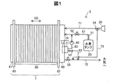
図2は、気液分離器10の外観構成を示す平面図である。図3は、気液分離器10の構成を示す断面図である。図2では、気液分離器10を第1のエンドプレート80からターミナルプレート82およびセルスタック90に向かう方向に見た場合の平面図を表す。上述のように、気液分離器10の一部は第1のエンドプレート80に形成されているので、図2,3では、第1のエンドプレート80の一部も描かれている。なお、図2では、気液分離器10に接続されている弁装置500も表されている。図3は、図2に示すA−A断面を表している。以降の図面では、特に断らない限り、燃料電池システム5が搭載された燃料電池自動車が水平面に配置されている状態における燃料電池システム5(気液分離器10)の各構成要素を表す。また、以降の図面では、X軸およびY軸は水平面と平行であり、Z軸は鉛直方向と平行である。また、+Z方向は鉛直上方を示し、−Z方向は鉛直下方を示す。また、+X方向は燃料電池自動車のフロント方向を示し、−X方向は燃料電池自動車のリア方向を示す。なお、本実施形態では、積層方向SDは、Y軸と平行である。
A2. Gas-liquid separator configuration:
FIG. 2 is a plan view showing an external configuration of the gas-
図2に示すように、カバー部材11は、第1のエンドプレート80のカバー対向面S80にボルトにより取り付けられている。カバー部材11の+X方向の端部には、弁装置500が接続されている。弁装置500は、排気排水弁53および排気排水弁53を開閉駆動するための駆動部を有している。なお、カバー部材11と弁装置500との接続部分の詳細については、後述する。カバー部材11の平面視形状は、X軸方向が長手方向となる略矩形であり、Y軸方向と平行な方向が厚み方向に相当する。
As shown in FIG. 2, the
図3に示すように、第1のエンドプレート80の内部に気液分離器形成部12が形成されている。気液分離器形成部12は、第1内壁部202を有し、第1のエンドプレート80の厚さ方向(Y軸方向)に延びるガス供給路210が形成されている。第1内壁部202は、カバー対向面S80に形成された開口と接続し、第1のエンドプレート80の厚さ方向(Y軸方向)に凹状に形成されている。第1内壁部202は、後述するカバー部材11の第2内壁部160と共に貯留部13を形成する。貯留部13は、Z軸方向につぶれた略球状の外観形状を有し、アノード側オフガスの流路として機能すると共にアノード側オフガスから分離された水を一時的に溜める機能を有する。ガス供給路210の−Y方向の端は、第1のエンドプレート80におけるターミナルプレート82側の端面に達している。また、ガス供給路210の+Y方向の端は、貯留部13の内部空間と連通している。ガス供給路210は、ターミナルプレート82を介してセルスタック90から排出されるアノード側オフガスを貯留部13に導く。
As shown in FIG. 3, the gas-liquid
カバー部材11において、第1のエンドプレート80のカバー対向面S80と対向する面(以下、「形成部対向面」と呼ぶ)S11には、開口が形成されている。カバー部材11は、かかる開口と接続してカバー部材11の厚さ方向(Y軸方向)に凹状に形成されている第2内壁部160を備える。カバー部材11の形成部対向面S11に形成されている開口の形状および大きさは、気液分離器形成部12のカバー対向面S80に形成された開口の形状および大きさと同じである。そして、これら2つの開口同士が対向するように、カバー部材11が配置されることにより、第1内壁部202と第2内壁部160とは接続され、上述の貯留部13が形成される。カバー部材11は、貯留部13内に突出部110を備える。突出部110は、第2内壁部160の底面から上方に突出している。突出部110の−Y方向の端面は、カバー部材11における形成部対向面S11よりも+Y方向にオフセットされている。このため、突出部110の−Y方向の端面に対して−Y方向に隣接する部分には隙間190が形成されている。なお、突出部110および隙間190の詳細については後述する。また、カバー部材11は、第2内壁部160(貯留部13)の底面の一部に斜面S101を有する。かかる斜面S101は、カバー部材11から気液分離器形成部12に向かう方向(−Y方向)に沿って次第に下方に傾斜している。
In the
図4は、気液分離器形成部12の構成を示す平面図である。図5は、気液分離器形成部12の構成を示す斜視図である。図4では、図2に示す状態からカバー部材11を取り外して、気液分離器形成部12が露呈した状態が表されている。
FIG. 4 is a plan view showing the configuration of the gas-liquid
気液分離器形成部12は、上述の第1内壁部202に加えて、ガス供給路形成部211と、囲み部221とを備えている。ガス供給路形成部211は、気液分離器形成部12における−X方向の端部に配置されており、ガス供給路210を形成する。具体的には、ガス供給路形成部211は、Y軸方向(積層方向SD)と平行に延びる断面が円形の内壁を有し、かかる内壁によってガス供給路210を形成する。なお、ガス供給路形成部211の+Y方向の端は、貯留部13へのガス流入口に相当する。図5において破線の矢印に示すように、ガス流入口から流入したオフガスは、カバー部材11に向かう。
The gas-liquid
囲み部221は、第1内壁部202の−Y方向の端部から+Y方向に突出してオフガス排出口220を囲んでいる。囲み部221は、略台形の断面形状を有し、また、Y軸と平行に延びるパイプ状の外観形状を有する。囲み部221は、第1壁部222と、第2壁部223と、第3壁部224とを有する。第1壁部222は、第1内壁部202の天井部分から下方に向かって突出し、Y−Z平面と略平行に配置されている。第2壁部223は、第1壁部222に対して+X方向に離れた位置において、第1壁部222と平行に配置されている。第3壁部224は、第1壁部222の下端と、第2壁部223の下端部とを接続する。ここで、第2壁部223の鉛直方向(Z軸方向)の長さは、第1壁部222の鉛直方向の長さよりも長い。したがって、第3壁部224は、+X方向に向かうにつれて次第に下方に向かうように傾斜している。上述の3つの壁部222〜224と、第1内壁部202の天井部分とにより、排出流路225が形成されている。排出流路225は、貯留部13からオフガス排出口220に向かうオフガスの流れを−Y方向に規制する。オフガス排出口220は、図4,5に示すように、排出流路225における−Y方向の突き当たり部分と、第2壁部223の内側部分との境界部分に形成されている。
The surrounding
図6は、図4に示す気液分離器形成部12のC−C断面を示す断面図である。図6に示すように、囲み部221の+Y方向の端面S221は、気液分離器形成部12全体としての+Y方向の端面であるカバー対向面S80よりも、−Y方向に距離d1だけオフセットされている。換言すると、囲み部221の端面S221は、カバー対向面S80からカバー部材11側へと突出していない。このように、囲み部221の+Y方向の端面S221を、カバー対向面S80よりも−Y方向にオフセットさせることにより、カバー部材11側に溜まった水が排出流路225内に浸入することを抑制している。
6 is a cross-sectional view showing a CC cross section of the gas-liquid
図4,5に示すように、第1内壁部202のうちの底面(−Z方向に配置されている面)は、第1の面S23と、第2の面S24とを有する。これら2つの面S23,S24は、いずれもカバー部材11の底面(第2内壁部160のうちの底面)と接する。第1の面S23は、第2の面S24の−X方向に位置して第2の面S24と接続している。第1の面S23は、囲み部221の鉛直下方に位置する。第1の面S23は、+X方向に沿って次第に下方に傾斜している。これに対して、第2の面S24は、+X方向に沿って次第に上方に傾斜している。したがって、図4に示すように、第1の面S23および第2の面S24の−Y方向の断面形状は、略V字型となっている。そして、第1の面S23と第2の面S24との接続部分(線状の部分)は、気液分離器10が載置された状態において気液分離器形成部12における最下点p21を含む。ここで、本実施形態においては、第1の面S23と囲み部221の第3壁部224とを略平行となるように構成している。なお、「略平行」とは、第1の面S23を延長させて得られる面と、第3壁部224を延長させて得られる面との間の角度が、0度以上且つ20度以下の範囲であることを意味する。なお、かかる範囲の上限は、20度に限らず90度よりも小さい任意の値としてもよい。このように、第1の面S23と囲み部221の第3壁部224とを略平行とする理由について、図7を用いて説明する。
As shown in FIGS. 4 and 5, the bottom surface (the surface disposed in the −Z direction) of the first
図7は、気液分離器10内(貯留部13内)に溜まった水と、囲み部221との位置関係を示す説明図である。図7(A)は、燃料電池自動車が水平面を走行している際の気液分離器形成部12の内部の状態を示し、図7(B)は、燃料電池自動車が上り坂を走行している際の気液分離器形成部12の内部の状態を示している。
FIG. 7 is an explanatory diagram showing the positional relationship between the water stored in the gas-liquid separator 10 (in the storage unit 13) and the surrounding
図7(A)に示すように、気液分離器形成部12の底部には、オフガスから分離された水W1が溜まっている。このとき、液面WS1の位置は、囲み部221の下端(第2壁部223と第3壁部224との交差部分)よりも低い。
As shown in FIG. 7A, water W1 separated from off-gas is collected at the bottom of the gas-liquid
このように水が溜まった状態で、燃料電池自動車が上り坂を走行すると、気液分離器形成部12の+X方向の端部が−X方向の端部よりも鉛直上方に位置するように、気液分離器10が配置されることになる。このとき、第1の面S23は、図7(A)の状態に比べて水平に近い状態となり、気液分離器形成部12の底部の水W1の大部分は、第1の面S23上に位置することとなる。ここで、第1の面S23は第3壁部224と略平行であるため、水W1の液面WS2は、第3壁部224と略平行となる。このため、第3壁部224と液面WS2との間の隙間G1のZ方向の長さは、いずれの位置においてもほぼ等しい。したがって、液面WS2が第3壁部224に接し、水W1が排出流路225からオフガス排出口220に吸い込まれることが抑制される。
When the fuel cell vehicle travels uphill with water accumulated in this way, the end in the + X direction of the gas-liquid
図8は、カバー部材11の構成を示す平面図である。図9は、カバー部材11の構成を示す斜視図である。図8,9では、第1のエンドプレート80に装着する前のカバー部材11を表している。
FIG. 8 is a plan view showing the configuration of the
カバー部材11は、上述した第2内壁部160、突出部110、および斜面S101に加えて、排水流路形成部120を備える。突出部110は、カバー部材11の第2内壁部160におけるガス流入口に対向する位置と、排水流路形成部120に形成された排水口121との間に配置されている。突出部110は、厚肉部111と薄肉部112とを備え、これらが一体化された構造を有する。厚肉部111は、薄肉部112に比べてZ軸方向の長さが大きく、第2内壁部160の底面と接している。上述したように、厚肉部111の−Y方向の端面S110は、カバー部材11全体としての−Y方向の端面である形成部対向面S11よりも+Y方向に距離d2だけオフセットされている。薄肉部112は、薄板状の外観形状を有し、厚肉部111に対して+X方向に位置する。薄肉部112の+Z方向の面は、厚肉部111の+Z方向の端面と一体化して1つの面(天井面)を形成している。薄肉部112の下端(−Z方向の端面)は、第2内壁部160の底面に接していない。したがって、薄肉部112は、厚肉部111に支持されている。厚肉部111および薄肉部112の天井面は、第2内壁部160に接していない。したがって、突出部110と第2内壁部160の天井面との間には空隙が形成されている。
The
第2内壁部160のうちの底面は、第3の面S13と、第4の面S14とを有する。第3の面S13は、上述の気液分離器形成部12の第1の面S23と接して1つの面を形成する。同様に、第4の面S14は、上述の気液分離器形成部12の第2の面S24と接して1つの面を形成する。したがって、第3の面S13および第4の面S14の+Y方向の断面形状は、第1の面S23および第2の面S24の−Y方向の断面形状と同様に、略V字型となっている。そして、第3の面S13および第4の面S14との接続部分(線状の部分)は、気液分離器10が載置された状態においてカバー部材11における最下点p11を含む。この最下点p11は、上述の気液分離器形成部12の最下点p21とY軸方向に対応する。上述の突出部110は、第3の面S13に接して配置されている。
The bottom surface of the second
斜面S101は、突出部110の−X方向に配置され、突出部110の下端に接している。斜面S101は、気液分離器形成部12に形成されているガス流入口に対向している。上述のように、斜面S101は、カバー部材11から気液分離器形成部12に向かう方向(−Y方向)に沿って次第に下方に傾斜している。換言すると、気液分離器形成部12からカバー部材11に向かう方向(+Y方向)に沿って次第に上方に傾斜している。斜面S101の下端、すなわち、−Y方向の端は、図3に示す隙間190の底面と接している。
The slope S101 is disposed in the −X direction of the
排水流路形成部120は、第2内壁部160のうちの底面に接して配置されている。排水流路形成部120の内部には、+X方向に延びる図示しない排水流路が形成されている。排水流路形成部120の−X方向の端部には、排水口121が形成されている。排水口121は、第2内壁部160の底面の近傍に位置して、貯留部13の内部に露呈している。なお、上述の排水流路の詳細構成については、後述する。貯留部13内に溜まった水は、排水口121から排水流路に排出される。
The drainage
貯留部13におけるオフガスの流れについて、図8を用いて説明する。ガス流入口から貯留部13に流入したオフガスのうちの大部分のオフガスは、斜面S101に当たって斜面S101に沿って上昇し、第2内壁部160における+Y方向の壁S102と、+Z方向の壁(天井面)S103と突出部110の上面とに囲まれた領域を、略+X方向に向かう。突出部110が存在するため、斜面S101に沿って上昇したオフガスが貯留部13の底面に向かう(−Z方向に向かう)ことが抑制される。突出部110の上面を通過したオフガスのうちの大部分のオフガスは、気液分離器形成部12に向かい、排出流路225を通ってオフガス排出口220から排出される。突出部110の上面を通過したオフガスのうちの残りのオフガスは、排水口121から水と共に排水流路に排出される。気液分離器形成部12のガス流入口から貯留部13に流入したオフガスのうちの極僅かのオフガスは、斜面S101に沿って下降して、図3に示す隙間190を+X方向に向かい、オフガス排出口220または排水口121から排出される。
The flow of off-gas in the
上述のように、気液分離器10内に供給されたオフガスは、貯留部13の壁面や突出部110の天井面にぶつかることにより向きを変えながら貯留部13内を流動して、気液分離器10から排出される。このとき、オフガスに含まれる水分は、オフガスが貯留部13の壁面や突出部110の上面に衝突した際にふるい落とされ、各壁面を下方に流れる。例えば、斜面S101における液体の水は、斜面S101に沿って下方に流れる。ここで、斜面S101の下端は隙間190の下端と接続しているため、また、隙間190の鉛直下方に位置する第3の面S13は+X方向に沿って下方に傾斜しているため、斜面S101を下降した水は、隙間190を通って+X方向に移動して排水口121に向かうこととなる。また、第2内壁部160のうち、斜面S101とは異なる壁においてふるい落とされた水は、各壁を下方に流れて貯留部13の底部に溜まり、排水口121から排水流路へと排出される。
As described above, the off-gas supplied into the gas-
ここで、排水口121はカバー部材11に形成されているのに対して、貯留部13のオフガス排出口220は気液分離器形成部12に形成されている。加えて、排水口121は貯留部13の底部に配置されているのに対して、オフガス排出口220は貯留部13の天井部近傍に配置されている。本実施形態では、このような構造とすることにより、排水口121とオフガス排出口220との間の距離を比較的長くして、排水口121近傍に溜まった水がオフガス排出口220に流入することを抑制する。また、突出部110を設けることにより、貯留部13に流入したオフガスが直線的に貯留部13の底部に向かうことを抑制する。このようにして、貯留部13の底部に溜まった水の水面にオフガスが直接ぶつかり、水が飛び散ってオフガス排出口220に流入することを抑制する。
Here, the
また、貯留部13におけるガス流入口とオフガス排出口220とをいずれも気液分離器形成部12側に設けると共に、これらガス流入口およびオフガス排出口220と対向するカバー部材11の第2内壁部160を+Y方向に凹状に形成することにより、貯留部13内におけるオフガスの流れを略U字状の流れとなるように制御している。上述の略U字状の流れとは、具体的には、オフガスが、ガス流入口からカバー部材11に向かい、貯留部13の壁をぶつかりながら略+X方向に移動し、カバー部材11から気液分離器形成部12に向かって移動してオフガス排出口220から排出される流れを意味する。本実施形態では、上述のように貯留部13内におけるオフガスの流れを略U字状の流れとすることにより、貯留部13内におけるオフガスの流路の延べ長さを比較的大きくしてオフガスから水を分離する機会をより多くしている。
Further, the gas inlet and the off-
図10は、気液分離器10内(貯留部13内)における溜まった水の配置を示す説明図である。図10(A)は、燃料電池自動車が水平面を走行している際のカバー部材11の内部の状態を示し、図10(B)は、燃料電池自動車が上り坂を走行している際のカバー部材11の内部の状態を示している。
FIG. 10 is an explanatory diagram showing the arrangement of accumulated water in the gas-liquid separator 10 (in the storage unit 13). 10A shows the internal state of the
図10(A)に示すように、カバー部材11の底部には、オフガスから分離された水W2が溜まっている。このとき、水W2の液面WS3は、排水口121の近傍に位置している。このため、水W2は排水口121から排出され易い。
As shown in FIG. 10A, water W2 separated from off-gas is collected at the bottom of the
ここで、本実施形態では、突出部110の+X方向の端面S111と、最下点p11との間の長さL1を短く設定している。具体的には、貯留部13(第2内壁部160)における+X方向の端面S161と最下点p11との間の長さL2に比べて、長さL1を短く設定している。このため、図10(B)に示すように、燃料電池自動車が上り坂を走行して水W2が突出部110側に移動した場合に、水W2の液面WS4の高さ(鉛直方向に沿った位置)を、長さL1がより長い構成に比べて、より上方に位置させることができる。それゆえ、長さL1がより長い構成に比べて、液面WS4を排水口121から比較的近い位置に配置させることができ、水W2が排水口121から排出されないことを抑制できる。
Here, in the present embodiment, the length L1 between the end surface S111 in the + X direction of the
図11は、気液分離器10と弁装置500との接続部分の構成を示す説明図である。図11(A)は、図3におけるB−B断面を示し、図11(B)は、図11(A)における領域Ar1を拡大して示し、図11(C)は、図11(B)における領域Ar2を拡大して示す。なお、図11(A)では、弁装置500の+X方向の一部の詳細構造については省略している。
FIG. 11 is an explanatory diagram showing a configuration of a connection portion between the gas-
図11(A)に示すように、排水流路形成部120の内部には、X軸方向に延びる排水流路122が形成されている。排水流路122の−X方向の端部は排水口121として形成されている。図11(B)に示すように、排水流路122の鉛直下方の面は、3つの面(第1底面151、第2底面152、および第3底面153)を有する。第1底面151、第2底面152、および第3底面153は、この順序で、排水口121から+X方向に並んでいる。第1底面151の鉛直方向の位置は、第2底面152の鉛直方向の位置よりも高い。また、第2底面152の鉛直方向の位置は、第3底面153の鉛直方向の位置よりも高い。したがって、図11(B)に示すように、排水流路122の底面の鉛直方向の位置は、+X方向に沿って階段状に下っている。
As shown in FIG. 11A, a
弁装置500は、−X方向に延びるパイプ状の接続部510を有する。接続部510の内部には、連通流路511が設けられている。気液分離器10に弁装置500が装着された状態において、接続部510は、排水流路122に挿入されている。連通流路511は、接続部510の内部をX軸方向に沿って貫通する貫通孔として形成されている。連通流路511の両端は開放され、−X方向の開放端は排水流路122と連通し、+X方向の開放端は弁装置500の内部に位置している。連通流路511の+X方向の開放端は、排気排水弁53により閉塞され得る。図11(B),(C)に示すように、接続部510の−X方向の端部は、第1底面151と第2底面152とを接続するZ軸方向に沿った壁面S151に対して、距離d4だけ+X方向にずれた位置に配置されている。これは、弁装置500または気液分離器10の製造ばらつきに起因して、接続部510の−X方向の端部が壁面S151にぶつかり、弁装置500が正常に気液分離器10に装着されないことを抑制するためである。
The
ここで、図11(B),(C)に示すように、連通流路511の鉛直下方の面(底面)512の鉛直方向に沿った位置と、第1底面151の鉛直方向に沿った位置とは、ほぼ等しい。したがって、貯留部13の底部に溜まった水が排出される際に排水流路122内に留まることを抑制でき、水の排出をスムーズに行なうことができる。排水流路122内に水が留まったまま燃料電池システム5の運転が停止し、燃料電池システム5の配置環境が非常に低温の環境となった場合、排水流路122内に留まっている水は過冷却水となり得る。この状態で燃料電池システム5が起動した場合、過冷却水が排気排水弁53に向かって移動して排気排水弁53において凍結するおそれがある。このように排気排水弁53において水が凍結すると、排気排水弁53が開かずに排水が行なわれなくなるおそれがある。加えて、排水流路122内に水が留まっている場合、かかる水が不連続に排気排水弁53から排出されて耳障りな音が発生するおそれがある。しかしながら、本実施形態の燃料電池システム5では、上述のように、排水流路122に水が滞留することを抑制できるので、排気排水弁53において水が凍結して開弁されないこと、および、耳障りな音が発生することを、抑制できる。
Here, as shown in FIGS. 11B and 11C, the position along the vertical direction of the vertically lower surface (bottom surface) 512 of the
なお、本実施形態において、上述した第1のエンドプレート80は、請求項におけるエンドプレートに相当する。また、囲み部221は請求項における排出口形成部に、斜面S101は請求項における斜面に、排気排水弁53は請求項における弁に、それぞれ相当する。
In the present embodiment, the
以上説明した本実施形態の燃料電池システム5に用いられる気液分離器10は、第1のエンドプレート80の一部として形成されている気液分離器形成部12と、第1のエンドプレート80に装着されるカバー部材11とにより構成されているので、第1のエンドプレート80とは別に気液分離器を用意する構成に比べて、第1のエンドプレート80と気液分離器10との合計の設置スペースの大型化を抑制できる。このため、燃料電池システム5の大型化を抑制できる。加えて、2つの部材を重ねることにより気液分離器10を構成するので、突出部110および第1の面S23や第2の面S24等の気液分離器10内部の構造を比較的容易に製造することができる。
The gas-
また、貯留部13におけるガス流入口とオフガス排出口220とをいずれも気液分離器形成部12側に設けると共に、これらガス流入口およびオフガス排出口220と対向するカバー部材11の第2内壁部160を+Y方向に凹状に形成しているため、貯留部13内におけるオフガスの流れを略U字状の流れとなるように制御できる。このため、貯留部13内におけるオフガスの流路の延べ長さを比較的大きくできる。したがって、オフガスから水を分離する機会をより多くできる。
Further, the gas inlet and the off-
また、排水口121をカバー部材11に形成してオフガス排出口220を気液分離器形成部12に形成すると共に、排水口121を貯留部13の底部に配置してオフガス排出口220を貯留部13の天井部近傍に配置している。このため、排水口121とオフガス排出口220との間の距離を比較的長くでき、排水口121近傍に溜まった水がオフガス排出口220に流入することを抑制できる。このため、オフガスからの水の分離効率を向上できる。
In addition, the
また、気液分離器10には、カバー部材11に突出部110を設けているので、ガス流入口からカバー部材11に向かって供給されたオフガスが、直線的に貯留部13の底部に向かうことが抑制される。このため、貯留部13の底部に溜まった水の液面にオフガスが直接ぶつかり、水が飛び散ってオフガス排出口220に流入することを抑制できる。加えて、突出部110を設けることにより、貯留部13に溜まった水が貯留部13内を流動するオフガスにより巻き上げられてガス流入口に向かう(戻る)ことを抑制できる。
Further, since the gas-
また、突出部110(厚肉部111)の端面S110を、カバー部材11全体としての−Y方向の端面である形成部対向面S11よりも+Y方向に距離d2だけオフセットさせることによって隙間190を形成し、且つ、かかる隙間190の底面と、ガス流入口と対向する斜面S101の下端とを接続している。このため、斜面S101を流れ落ちる液体の水を、隙間190を介して排水口121に向かわせることができる。加えて、隙間190の底面(第3の面S13)を、+X方向に沿って下方に傾斜して形成しているので、隙間190において水が排水口121に向かうことを促進できる。
Further, the
また、突出部110の端面S111と最下点p11との間の長さL1を、第2内壁部160における+X方向の端面S161と最下点p11との間の長さL2に比べて短く設定しているため、長さL1をより長くした構成に比べて、燃料電池自動車が上り坂を走行する場合(気液分離器10がX軸方向に傾斜する場合)に、貯留部13の底部に溜まった水の液面を排水口121に近づけることができる。このため、貯留部13に溜まった水の排出を促進できる。
Further, the length L1 between the end surface S111 of the projecting
また、排水流路122における第1底面151の鉛直方向の位置を、接続部510の連通流路511の底面512の鉛直方向の位置とほぼ同じにしているので、貯留部13の底部に溜まった水が排出される際に排水流路122内に留まることを抑制でき、水の排出をスムーズに行なうことができる。このため、排水流路122に留まっている水に起因して排気排水弁53が開弁されないこと、および耳障りな音が発生することを、抑制できる。
In addition, since the vertical position of the first
また、囲み部221の+Y方向の端面S221を、気液分離器形成部12全体としての+Y方向の端面であるカバー対向面S80よりも、−Y方向に距離d1だけオフセットさせているので、カバー部材11側に溜まった水が排出流路225内に浸入することを抑制できる。加えて、貯留部13の底面(第1の面S23および第3の面S13)と囲み部221の第3壁部224とを、互いに略平行に形成しているので、燃料電池自動車が上り坂を走行する場合に、貯留部13に溜まった水の液面と囲み部221との間の距離を比較的大きくできる。このため、水が排出流路225からオフガス排出口220に吸い込まれることを抑制できる。
Further, since the end surface S221 in the + Y direction of the surrounding
B.変形例:
B1.変形例1:
上記実施形態において、排水流路122の第1底面151の鉛直方向に沿った位置と、連通流路511の底面512の鉛直方向に沿った位置とは、略同一であったが、本発明はこれに限定されない。図12は、変形例における気液分離器10と弁装置との接続部分を拡大して示す説明図である。図12(A)は、かかる接続部分の変形例における第1の態様を示し、図12(B)は、かかる接続部分の変形例における第2の態様を示す。
B. Variations:
B1. Modification 1:
In the above embodiment, the position along the vertical direction of the first
図12(A)の態様では、排水流路122の第1底面151の鉛直方向に沿った位置は、連通流路511の底面512aの鉛直方向に沿った位置よりも上方である。このような態様においても、貯留部13の底部に溜まった水が排出される際に排水流路122内に留まることを抑制できる。
12A, the position along the vertical direction of the first
図12(B)の態様では、連通流路511の底面512bは、−X方向の端部が最も鉛直上方に位置し、+X方向に沿って下方に傾斜している。ここで、底面512bの−X方向の端部の鉛直方向に沿った位置は、排水流路122の第1底面151の鉛直方向に沿った位置とほぼ等しい。したがって、第1底面151の鉛直方向に沿った位置は、底面512bのいずれの部分における鉛直方向に沿った位置と同じ又はより上方である。
In the aspect of FIG. 12B, the
以上の変形例および上記実施形態から理解できるように、排水流路122の第1底面151の鉛直方向に沿った位置が、連通流路511の底面512bの鉛直方向に沿った位置と同じ又はより上方である気液分離器に、本発明を適用できる。
As can be understood from the above modification and the above embodiment, the position along the vertical direction of the first
B2.変形例2:
上記実施形態では、囲み部221の+Y方向の端面S221が気液分離器形成部12全体としての+Y方向の端面であるカバー対向面S80よりも−Y方向に距離d1だけオフセットされている点と、貯留部13の底面(第1の面S23および第3の面S13)と囲み部221の第3壁部224とを互いに略平行に形成している点とがいずれも実現されていたが、これら2点のうち、いずれか1点のみを実現してもよい。かかる構成においても、オフガスから分離された水が排出流路225からオフガス排出口220に吸い込まれることを抑制できる。
B2. Modification 2:
In the above embodiment, the end surface S221 in the + Y direction of the surrounding
B3.変形例3:
上記実施形態における気液分離器10の構成は、あくまでも一例であり、種々変更可能である。例えば、気液分離器10へのオフガスの流入口およびオフガス排出口220は、いずれも気液分離器形成部12に形成されていたが、これらのうちの少なくとも一方を、カバー部材11に形成してもよい。また、排水流路形成部120は、カバー部材11(第2内壁部160)の底部に形成されていたが、気液分離器形成部12(第1内壁部202)の底部に形成されてもよい。また、気液分離器10において突出部110を省略してもよい。かかる構成においても、気液分離器10の一部を第1のエンドプレート80内に形成するので、燃料電池システムの大型化を抑制できる。また、隙間190の底面に傾斜を設けなくともよい。少なくとも隙間190が形成されていることにより、斜面S101を下って斜面S101の下端に達した水が、排水口121に向かうことが妨げられない。また、図10に示す長さL1を、長さL2と同じまたはより長くしてもよい。また、囲み部221の下方の壁である第3壁部224は、第1の面S23と略平行であったが、第1の面S23と略平行でなくともよい。この構成においても、囲み部221の+Y方向の端面S221を、カバー対向面S80よりも−Y方向にオフセットさせることにより、カバー部材11側に溜まった水が排出流路225内に流入することを抑制できる。上記実施形態において、気液分離器形成部12は、第1のエンドプレート80に形成されていたが、第1のエンドプレート80に代えて、第2のエンドプレート81に形成されてもよい。この構成においては、水素ガスの供給系および排出系を、第2のエンドプレート81側に設けると共に、第2のエンドプレート81およびターミナルプレート83に、アノード側反応ガスの流通用のマニホールドと連通するための貫通孔を設けてもよい。
B3. Modification 3:
The structure of the gas-
本発明は、上述の実施形態および変形例に限られるものではなく、その趣旨を逸脱しない範囲において種々の構成で実現することができる。例えば、発明の概要の欄に記載した各形態中の技術的特徴に対応する実施形態、変形例中の技術的特徴は、上述の課題の一部又は全部を解決するために、あるいは、上述の効果の一部又は全部を達成するために、適宜、差し替えや、組み合わせを行うことが可能である。また、その技術的特徴が本明細書中に必須なものとして説明されていなければ、適宜、削除することが可能である。 The present invention is not limited to the above-described embodiments and modifications, and can be realized with various configurations without departing from the spirit of the present invention. For example, the technical features in the embodiments and the modifications corresponding to the technical features in each embodiment described in the summary section of the invention are to solve some or all of the above-described problems, or In order to achieve part or all of the effects, replacement or combination can be performed as appropriate. Further, if the technical feature is not described as essential in the present specification, it can be deleted as appropriate.
5…燃料電池システム
7…燃料電池
10…気液分離器
11…カバー部材
12…気液分離器形成部
13…貯留部
20…水素タンク
30…エアコンプレッサ
40…循環ポンプ
51…遮断弁
52…インジェクタ
53…排気排水弁
54…三方弁
55…圧力調整弁
61…燃料ガス供給路
62…燃料ガス循環路
63…燃料ガス排出路
71…酸化剤ガス供給路
72…酸化剤ガス排出路
73…バイパス流路
80…第1のエンドプレート
81…第2のエンドプレート
82…ターミナルプレート
83…ターミナルプレート
90…セルスタック
110…突出部
111…厚肉部
112…薄肉部
120…排水流路形成部
121…排水口
122…排水流路
151…第1底面
152…第2底面
153…第3底面
160…第2内壁部
190…隙間
202…第1内壁部
210…ガス供給路
211…ガス供給路形成部
220…オフガス排出口
221…囲み部
222…第1壁部
223…第2壁部
224…第3壁部
225…排出流路
500…弁装置
510…接続部
511…連通流路
512…底面
512a…底面
512b…底面
S13…第3の面
Ar1…領域
Ar2…領域
G1…隙間
S11…形成部対向面
S14…第4の面
S23…第1の面
S24…第2の面
S80…カバー対向面
S101…斜面
S102…壁
S103…壁(天井面)
S110…端面
S111…端面
S151…壁面
S161…端面
S221…端面
SD…積層方向
W1…水
W2…水
WS1…液面
WS2…液面
WS3…液面
WS4…液面
d1…距離
d2…距離
d4…距離
p11…最下点
p21…最下点
DESCRIPTION OF
S103: Wall (ceiling surface)
S110 ... End surface S111 ... End surface S151 ... Wall surface S161 ... End surface S221 ... End surface SD ... Lamination direction W1 ... Water W2 ... Water WS1 ... Liquid surface WS2 ... Liquid surface WS3 ... Liquid surface WS4 ... Liquid surface d1 ... Distance d2 ... Distance d4 ... Distance p11 ... Bottom point p21 ... Bottom point
Claims (5)
前記エンドプレートに形成され、前記エンドプレートにおける前記積層方向の端面のうちの前記セルスタックとは反対側の端面に開口し、前記気液分離器の一部を構成する気液分離器形成部と、
前記気液分離器形成部の開口を覆って配置され、前記気液分離器の一部を構成するカバー部材と、
を備え、
前記気液分離器形成部は、
前記オフガスの排出口が形成されており、前記オフガスの流路として機能すると共に前記オフガスから分離された水が溜まる貯留部の一部を形成する第1の内壁部であって、前記開口に接続して前記エンドプレートの厚さ方向に凹状に形成されている第1の内壁部と、
前記気液分離器形成部から前記カバー部材に向かう第1の方向に沿って前記第1の内壁部から突出して前記排出口を囲む囲み部と、
を有し、
前記囲み部における前記第1の方向の端面は、前記気液分離器形成部全体における前記第1の方向の端面から前記第1の方向とは反対方向にオフセットされており、
前記カバー部材は、
前記カバー部材における前記気液分離器形成部と対向する面に形成された開口に接続して前記カバー部材の厚さ方向に凹状に形成されている第2の内壁部であって、前記第1の内壁部と前記積層方向に対向して配置されて、前記第1の内壁部と共に前記貯留部を形成する第2の内壁部と、
前記貯留部に溜まった水を排出する排水流路であって、自身の端部に前記第2の内壁部の底面の近傍に配置されて前記貯留部の内側に露呈している排水口が形成された排水流路を、形成する排水流路形成部と、
前記カバー部材の前記第2の内壁部に形成された斜面と、
を有し、
前記カバー部材の前記第2の内壁部は、前記排水口と繋がり、
前記斜面は、前記第1の方向とは反対方向に沿って次第に下方に傾斜する、
気液分離器。 Included in off-gas discharged from a fuel cell having a cell stack having a plurality of stacked single cells and an end plate disposed outside the cell stack in the stacking direction of the plurality of single cells. A gas-liquid separator that separates and discharges water,
A gas-liquid separator forming portion that is formed on the end plate, opens to an end surface of the end plate in the stacking direction opposite to the cell stack, and forms a part of the gas-liquid separator; ,
A cover member that is arranged to cover the opening of the gas-liquid separator forming part and constitutes a part of the gas-liquid separator;
With
The gas-liquid separator forming unit is
The off-gas discharge port is formed, and serves as a flow path for the off-gas, and is a first inner wall portion that forms a part of a storage portion in which water separated from the off-gas accumulates, and is connected to the opening A first inner wall formed in a concave shape in the thickness direction of the end plate;
A surrounding portion that protrudes from the first inner wall portion along the first direction from the gas-liquid separator forming portion toward the cover member and surrounds the discharge port;
Have
The end surface in the first direction of the surrounding portion is offset in the direction opposite to the first direction from the end surface of the first direction in the entire gas-liquid separator forming unit ,
The cover member is
A second inner wall connected to an opening formed on a surface of the cover member facing the gas-liquid separator forming portion and formed in a concave shape in the thickness direction of the cover member; A second inner wall portion that is disposed opposite the inner wall portion in the stacking direction and forms the storage portion together with the first inner wall portion,
A drainage channel for discharging water accumulated in the reservoir, wherein a drainage port is formed at the end of the drainage channel in the vicinity of the bottom surface of the second inner wall and exposed to the inside of the reservoir. A drainage channel forming part for forming the drainage channel,
A slope formed on the second inner wall of the cover member;
Have
The second inner wall portion of the cover member is connected to the drain port,
The inclined surface is gradually inclined downward along a direction opposite to the first direction.
Gas-liquid separator.
前記エンドプレートに形成され、前記エンドプレートにおける前記積層方向の端面のうちの前記セルスタックとは反対側の端面に開口し、前記気液分離器の一部を構成する気液分離器形成部と、
前記気液分離器形成部の開口を覆って配置され、前記気液分離器の一部を構成するカバー部材と、
を備え、
前記気液分離器形成部は、
前記オフガスの排出口が形成され、前記オフガスの流路として機能すると共に前記オフガスから分離された水が溜まる貯留部の一部を形成する第1の内壁部であって、前記開口に接続して前記エンドプレートの厚さ方向に凹状に形成されている第1の内壁部と、
前記気液分離器形成部から前記カバー部材に向かう第1の方向に沿って前記第1の内壁部から突出して前記排出口を囲む囲み部と、
を有し、
前記囲み部の外表面のうち、前記気液分離器が載置された状態において鉛直下方に位置する外表面は、前記貯留部の底面と略平行であり、
前記カバー部材は、
前記カバー部材における前記気液分離器形成部と対向する面に形成された開口に接続して前記カバー部材の厚さ方向に凹状に形成されている第2の内壁部であって、前記第1の内壁部と前記積層方向に対向して配置されて、前記第1の内壁部と共に前記貯留部を形成する第2の内壁部と、
前記貯留部に溜まった水を排出する排水流路であって、自身の端部に前記第2の内壁部の底面の近傍に配置されて前記貯留部の内側に露呈している排水口が形成された排水流路を、形成する排水流路形成部と、
前記カバー部材の前記第2の内壁部に形成された斜面と、
を有し、
前記カバー部材の前記第2の内壁部は、前記排水口と繋がり、
前記斜面は、前記第1の方向とは反対方向に沿って次第に下方に傾斜する、
気液分離器。 Included in off-gas discharged from a fuel cell having a cell stack having a plurality of stacked single cells and an end plate disposed outside the cell stack in the stacking direction of the plurality of single cells. A gas-liquid separator that separates and discharges water,
A gas-liquid separator forming portion that is formed on the end plate, opens to an end surface of the end plate in the stacking direction opposite to the cell stack, and forms a part of the gas-liquid separator; ,
A cover member that is arranged to cover the opening of the gas-liquid separator forming part and constitutes a part of the gas-liquid separator;
With
The gas-liquid separator forming unit is
A first inner wall portion that forms a part of a storage portion in which a discharge port for the off gas is formed, functions as a flow path for the off gas, and stores water separated from the off gas, and is connected to the opening. A first inner wall formed in a concave shape in the thickness direction of the end plate;
A surrounding portion that protrudes from the first inner wall portion along the first direction from the gas-liquid separator forming portion toward the cover member and surrounds the discharge port;
Have
Of the outer surface of the surrounding portion, the outer surface of the gas-liquid separator is positioned vertically downward in the mounted state, the Ri bottom surface der substantially parallel of the reservoir,
The cover member is
A second inner wall connected to an opening formed on a surface of the cover member facing the gas-liquid separator forming portion and formed in a concave shape in the thickness direction of the cover member; A second inner wall portion that is disposed opposite the inner wall portion in the stacking direction and forms the storage portion together with the first inner wall portion,
A drainage channel for discharging water accumulated in the reservoir, wherein a drainage port is formed at the end of the drainage channel in the vicinity of the bottom surface of the second inner wall and exposed to the inside of the reservoir. A drainage channel forming part for forming the drainage channel,
A slope formed on the second inner wall of the cover member;
Have
The second inner wall portion of the cover member is connected to the drain port,
The inclined surface is gradually inclined downward along a direction opposite to the first direction.
Gas-liquid separator.
前記第1の内壁部には、前記気液分離器への前記オフガスの流入口が形成されている、気液分離器。 The gas-liquid separator according to claim 1 or 2,
Wherein the first inner wall portion, the inlet of the off-gas to the gas-liquid separator is formed, the gas-liquid separator.
積層された複数の単セルを有するセルスタックと、前記セルスタックに対して前記複数の単セルの積層方向の外側に配置されているエンドプレートと、を有する燃料電池と、
前記燃料電池から排出されたオフガスに含まれる水を分離して排出する気液分離器と、
を備え、
前記気液分離器は、
前記エンドプレートに形成され、前記エンドプレートにおける前記積層方向の端面のうちの前記セルスタックとは反対側の端面に開口し、前記気液分離器の一部を構成する気液分離器形成部と、
前記気液分離器形成部の開口を覆って配置され、前記気液分離器の一部を構成するカバー部材と、
を有し、
前記気液分離器形成部は、
前記オフガスの排出口が形成されており、前記オフガスの流路として機能すると共に前記オフガスから分離された水が溜まる貯留部の一部を形成する第1の内壁部であって、前記開口に接続して前記エンドプレートの厚さ方向に凹状に形成されている第1の内壁部と、
前記気液分離器形成部から前記カバー部材に向かう第1の方向に沿って前記第1の内壁部から突出して前記排出口を囲む囲み部と、
を有し、
前記囲み部における前記第1の方向の端面は、前記気液分離器形成部全体における前記第1の方向の端面から前記第1の方向とは反対方向にオフセットされており、
前記カバー部材は、
前記カバー部材における前記気液分離器形成部と対向する面に形成された開口に接続して前記カバー部材の厚さ方向に凹状に形成されている第2の内壁部であって、前記第1の内壁部と前記積層方向に対向して配置されて、前記第1の内壁部と共に前記貯留部を形成する第2の内壁部と、
前記貯留部に溜まった水を排出する排水流路であって、自身の端部に前記第2の内壁部の底面の近傍に配置されて前記貯留部の内側に露呈している排水口が形成された排水流路を、形成する排水流路形成部と、
前記カバー部材の前記第2の内壁部に形成された斜面と、
を有し、
前記カバー部材の前記第2の内壁部は、前記排水口と繋がり、
前記斜面は、前記第1の方向とは反対方向に沿って次第に下方に傾斜する、
燃料電池システム。 A fuel cell system,
A fuel cell comprising: a cell stack having a plurality of stacked single cells; and an end plate disposed outside the cell stack in the stacking direction of the plurality of single cells;
A gas-liquid separator that separates and discharges water contained in the off-gas discharged from the fuel cell;
With
The gas-liquid separator is
A gas-liquid separator forming portion that is formed on the end plate, opens to an end surface of the end plate in the stacking direction opposite to the cell stack, and forms a part of the gas-liquid separator; ,
A cover member that is arranged to cover the opening of the gas-liquid separator forming part and constitutes a part of the gas-liquid separator;
Have
The gas-liquid separator forming unit is
The off-gas discharge port is formed, and serves as a flow path for the off-gas, and is a first inner wall portion that forms a part of a storage portion in which water separated from the off-gas accumulates, and is connected to the opening A first inner wall formed in a concave shape in the thickness direction of the end plate;
A surrounding portion that protrudes from the first inner wall portion along the first direction from the gas-liquid separator forming portion toward the cover member and surrounds the discharge port;
Have
The end surface in the first direction of the surrounding portion is offset in the direction opposite to the first direction from the end surface of the first direction in the entire gas-liquid separator forming unit ,
The cover member is
A second inner wall connected to an opening formed on a surface of the cover member facing the gas-liquid separator forming portion and formed in a concave shape in the thickness direction of the cover member; A second inner wall portion that is disposed opposite the inner wall portion in the stacking direction and forms the storage portion together with the first inner wall portion,
A drainage channel for discharging water accumulated in the reservoir, wherein a drainage port is formed at the end of the drainage channel in the vicinity of the bottom surface of the second inner wall and exposed to the inside of the reservoir. A drainage channel forming part for forming the drainage channel,
A slope formed on the second inner wall of the cover member;
Have
The second inner wall portion of the cover member is connected to the drain port,
The inclined surface is gradually inclined downward along a direction opposite to the first direction.
Fuel cell system.
積層された複数の単セルを有するセルスタックと、前記セルスタックに対して前記複数の単セルの積層方向の外側に配置されているエンドプレートと、を有する燃料電池と、
前記燃料電池から排出されたオフガスに含まれる水を分離して排出する気液分離器と、
を備え、
前記気液分離器は、
前記エンドプレートに形成され、前記エンドプレートにおける前記積層方向の端面のうちの前記セルスタックとは反対側の端面に開口し、前記気液分離器の一部を構成する気液分離器形成部と、
前記気液分離器形成部の開口を覆って配置され、前記気液分離器の一部を構成するカバー部材と、
を有し、
前記気液分離器形成部は、
前記オフガスの排出口が形成されており、前記オフガスの流路として機能すると共に前記オフガスから分離された水が溜まる貯留部の一部を形成する第1の内壁部であって、前記開口に接続して前記エンドプレートの厚さ方向に凹状に形成されている第1の内壁部と、
前記気液分離器形成部から前記カバー部材に向かう第1の方向に沿って前記第1の内壁部から突出して前記排出口を囲む囲み部と、
を有し、
前記囲み部の外表面のうち、前記気液分離器が載置された状態において鉛直下方に位置する外表面は、前記貯留部の底面と略平行であり、
前記カバー部材は、
前記カバー部材における前記気液分離器形成部と対向する面に形成された開口に接続して前記カバー部材の厚さ方向に凹状に形成されている第2の内壁部であって、前記第1の内壁部と前記積層方向に対向して配置されて、前記第1の内壁部と共に前記貯留部を形成する第2の内壁部と、
前記貯留部に溜まった水を排出する排水流路であって、自身の端部に前記第2の内壁部の底面の近傍に配置されて前記貯留部の内側に露呈している排水口が形成された排水流路を、形成する排水流路形成部と、
前記カバー部材の前記第2の内壁部に形成された斜面と、
を有し、
前記カバー部材の前記第2の内壁部は、前記排水口と繋がり、
前記斜面は、前記第1の方向とは反対方向に沿って次第に下方に傾斜する、
燃料電池システム。 A fuel cell system,
A fuel cell comprising: a cell stack having a plurality of stacked single cells; and an end plate disposed outside the cell stack in the stacking direction of the plurality of single cells;
A gas-liquid separator that separates and discharges water contained in the off-gas discharged from the fuel cell;
With
The gas-liquid separator is
A gas-liquid separator forming portion that is formed on the end plate, opens to an end surface of the end plate in the stacking direction opposite to the cell stack, and forms a part of the gas-liquid separator; ,
A cover member that is arranged to cover the opening of the gas-liquid separator forming part and constitutes a part of the gas-liquid separator;
Have
The gas-liquid separator forming unit is
The off-gas discharge port is formed, and serves as a flow path for the off-gas, and is a first inner wall portion that forms a part of a storage portion in which water separated from the off-gas accumulates, and is connected to the opening A first inner wall formed in a concave shape in the thickness direction of the end plate;
A surrounding portion that protrudes from the first inner wall portion along the first direction from the gas-liquid separator forming portion toward the cover member and surrounds the discharge port;
Have
Of the outer surface of the surrounding portion, the outer surface of the gas-liquid separator is positioned vertically downward in the mounted state, the Ri bottom surface der substantially parallel of the reservoir,
The cover member is
A second inner wall connected to an opening formed on a surface of the cover member facing the gas-liquid separator forming portion and formed in a concave shape in the thickness direction of the cover member; A second inner wall portion that is disposed opposite the inner wall portion in the stacking direction and forms the storage portion together with the first inner wall portion,
A drainage channel for discharging water accumulated in the reservoir, wherein a drainage port is formed at the end of the drainage channel in the vicinity of the bottom surface of the second inner wall and exposed to the inside of the reservoir. A drainage channel forming part for forming the drainage channel,
A slope formed on the second inner wall of the cover member;
Have
The second inner wall portion of the cover member is connected to the drain port,
The inclined surface is gradually inclined downward along a direction opposite to the first direction.
Fuel cell system.
Priority Applications (6)
| Application Number | Priority Date | Filing Date | Title |
|---|---|---|---|
| JP2014231294A JP6237582B2 (en) | 2014-11-14 | 2014-11-14 | Gas-liquid separator and fuel cell system |
| DE102015117741.2A DE102015117741B9 (en) | 2014-11-14 | 2015-10-19 | Gas-liquid separator and fuel cell system |
| CA2909869A CA2909869C (en) | 2014-11-14 | 2015-10-22 | Gas liquid separator and fuel cell system |
| KR1020150155008A KR101848980B1 (en) | 2014-11-14 | 2015-11-05 | Gas liquid separator and fuel cell system |
| US14/934,632 US10044052B2 (en) | 2014-11-14 | 2015-11-06 | Gas liquid separator and fuel cell system |
| CN201510770103.0A CN105609825B (en) | 2014-11-14 | 2015-11-12 | Gas-liquid separator and fuel cell system |
Applications Claiming Priority (1)
| Application Number | Priority Date | Filing Date | Title |
|---|---|---|---|
| JP2014231294A JP6237582B2 (en) | 2014-11-14 | 2014-11-14 | Gas-liquid separator and fuel cell system |
Publications (3)
| Publication Number | Publication Date |
|---|---|
| JP2016096012A JP2016096012A (en) | 2016-05-26 |
| JP2016096012A5 JP2016096012A5 (en) | 2016-07-07 |
| JP6237582B2 true JP6237582B2 (en) | 2017-11-29 |
Family
ID=55855671
Family Applications (1)
| Application Number | Title | Priority Date | Filing Date |
|---|---|---|---|
| JP2014231294A Active JP6237582B2 (en) | 2014-11-14 | 2014-11-14 | Gas-liquid separator and fuel cell system |
Country Status (6)
| Country | Link |
|---|---|
| US (1) | US10044052B2 (en) |
| JP (1) | JP6237582B2 (en) |
| KR (1) | KR101848980B1 (en) |
| CN (1) | CN105609825B (en) |
| CA (1) | CA2909869C (en) |
| DE (1) | DE102015117741B9 (en) |
Families Citing this family (15)
| Publication number | Priority date | Publication date | Assignee | Title |
|---|---|---|---|---|
| WO2015085295A2 (en) * | 2013-12-07 | 2015-06-11 | Novomer, Inc. | Nanofiltration membranes and methods of use |
| JP6295921B2 (en) * | 2014-10-31 | 2018-03-20 | トヨタ紡織株式会社 | Fuel cell gas-liquid separator |
| JP6168032B2 (en) * | 2014-11-14 | 2017-07-26 | トヨタ自動車株式会社 | Fuel cell system |
| JP6187433B2 (en) | 2014-11-14 | 2017-08-30 | トヨタ自動車株式会社 | Gas-liquid separator and fuel cell system |
| DE102017107479A1 (en) * | 2017-04-07 | 2018-10-11 | Proton Motor Fuel Cell Gmbh | Fuel cell system with media management panel |
| JP7063724B2 (en) * | 2018-05-25 | 2022-05-09 | トヨタ自動車株式会社 | Exhaust drainage unit for fuel cell system |
| JP7024651B2 (en) * | 2018-07-27 | 2022-02-24 | トヨタ自動車株式会社 | Fuel cell system and fuel cell system control method |
| JP7287082B2 (en) * | 2019-04-15 | 2023-06-06 | 株式会社アイシン | gas-liquid separator |
| CN110350227B (en) * | 2019-08-11 | 2024-02-06 | 河南豫氢动力有限公司 | Fuel cell end plate with hydrogen-water separation function |
| JP7267880B2 (en) * | 2019-09-06 | 2023-05-02 | 株式会社Soken | fuel cell system |
| CN112993329B (en) * | 2019-12-12 | 2022-03-15 | 中国科学院大连化学物理研究所 | Method for recycling reclaimed water in high-temperature tail gas of fuel cell |
| JP2022062750A (en) * | 2020-10-09 | 2022-04-21 | トヨタ自動車株式会社 | Fuel cell system |
| CN112516689B (en) * | 2020-11-10 | 2022-05-17 | 一汽解放汽车有限公司 | Water-gas separation device and fuel cell system |
| CN113193212B (en) * | 2021-04-09 | 2022-06-03 | 电子科技大学 | Fuel cell anode drainage and impurity removal integrated device and control method thereof |
| CN115036538B (en) * | 2022-06-20 | 2023-05-23 | 武汉众宇动力系统科技有限公司 | Gas-liquid separator for hydrogen fuel cell and gas-liquid separation method |
Family Cites Families (16)
| Publication number | Priority date | Publication date | Assignee | Title |
|---|---|---|---|---|
| KR100685068B1 (en) * | 2001-09-27 | 2007-02-22 | 지멘스 악티엔게젤샤프트 | Fuel cell block |
| JP2005116354A (en) * | 2003-10-08 | 2005-04-28 | Nissan Motor Co Ltd | Separator device and fuel system device of fuel cell |
| JP4395046B2 (en) | 2004-10-22 | 2010-01-06 | 本田技研工業株式会社 | Gas-liquid separator for in-vehicle fuel cell |
| JP2008066087A (en) * | 2006-09-06 | 2008-03-21 | Toyota Motor Corp | Fuel cell system |
| JP2008097972A (en) * | 2006-10-11 | 2008-04-24 | Toyota Motor Corp | Fuel cell system, and gas-liquid separator |
| JP5245393B2 (en) * | 2007-12-25 | 2013-07-24 | トヨタ紡織株式会社 | Gas-liquid separator for fuel cell system |
| US20100009223A1 (en) * | 2008-06-23 | 2010-01-14 | Nuvera Fuel Cells, Inc. | Fuel cell stack with integrated process endplates |
| JP5430318B2 (en) | 2009-09-24 | 2014-02-26 | 本田技研工業株式会社 | Fuel cell stack |
| JP5306842B2 (en) * | 2009-02-03 | 2013-10-02 | トヨタ自動車株式会社 | Integrated device of gas-liquid separator and diluter |
| JP5136522B2 (en) | 2009-07-07 | 2013-02-06 | 日産自動車株式会社 | Gas-liquid separator for vehicles |
| ES2391242T3 (en) | 2009-07-30 | 2012-11-22 | Siemens Aktiengesellschaft | Cascade fuel cell device with several stages |
| JP5045726B2 (en) * | 2009-10-19 | 2012-10-10 | トヨタ自動車株式会社 | Fuel cell system |
| JP2014231294A (en) | 2013-05-29 | 2014-12-11 | 小島プレス工業株式会社 | Pedestrian protection device for vehicle |
| JP6103236B2 (en) * | 2013-10-17 | 2017-03-29 | トヨタ紡織株式会社 | Gas-liquid separator |
| JP6295920B2 (en) * | 2014-10-31 | 2018-03-20 | トヨタ紡織株式会社 | Fuel cell end plate |
| JP6187433B2 (en) | 2014-11-14 | 2017-08-30 | トヨタ自動車株式会社 | Gas-liquid separator and fuel cell system |
-
2014
- 2014-11-14 JP JP2014231294A patent/JP6237582B2/en active Active
-
2015
- 2015-10-19 DE DE102015117741.2A patent/DE102015117741B9/en active Active
- 2015-10-22 CA CA2909869A patent/CA2909869C/en active Active
- 2015-11-05 KR KR1020150155008A patent/KR101848980B1/en active IP Right Grant
- 2015-11-06 US US14/934,632 patent/US10044052B2/en active Active
- 2015-11-12 CN CN201510770103.0A patent/CN105609825B/en active Active
Also Published As
| Publication number | Publication date |
|---|---|
| CA2909869C (en) | 2017-10-31 |
| DE102015117741B4 (en) | 2019-04-18 |
| CN105609825A (en) | 2016-05-25 |
| JP2016096012A (en) | 2016-05-26 |
| DE102015117741B9 (en) | 2019-08-01 |
| KR101848980B1 (en) | 2018-04-13 |
| CN105609825B (en) | 2018-01-02 |
| KR20160058007A (en) | 2016-05-24 |
| DE102015117741A1 (en) | 2016-05-19 |
| US20160141693A1 (en) | 2016-05-19 |
| US10044052B2 (en) | 2018-08-07 |
| CA2909869A1 (en) | 2016-05-14 |
Similar Documents
| Publication | Publication Date | Title |
|---|---|---|
| JP6237582B2 (en) | Gas-liquid separator and fuel cell system | |
| JP5591074B2 (en) | Fuel cell system | |
| JP6164198B2 (en) | Fuel cell | |
| KR101981865B1 (en) | Fuel cell vehicle | |
| JP6839620B2 (en) | Gas-liquid separator | |
| KR101808970B1 (en) | Separator and fuel cell | |
| US20100183944A1 (en) | Fuel cell, fuel cell-equipped vehicle, and membrane electrode unit | |
| JP6187433B2 (en) | Gas-liquid separator and fuel cell system | |
| JP2018114816A (en) | Fuel cell vehicle | |
| JP2006221947A (en) | Apparatus for separating vapor and liquid | |
| JP2021185577A (en) | Vapor liquid separator for fuel cell | |
| JP5128909B2 (en) | Polymer electrolyte fuel cell | |
| JP7115229B2 (en) | FUEL CELL, FUEL CELL MOUNTING DEVICE, AND FUEL CELL MANUFACTURING METHOD | |
| JP2012099382A (en) | Separator for fuel cell, fuel cell | |
| JP7120961B2 (en) | Gas-liquid separator | |
| JP5437089B2 (en) | Fuel cell system | |
| JPWO2015133200A1 (en) | Fluid control valve | |
| JP2015060732A (en) | Fuel cell | |
| JP2008293847A (en) | Fuel cell system | |
| JP5189898B2 (en) | Diluter | |
| JP2019160656A (en) | Fuel cell system | |
| JP2006120439A (en) | On-vehicle fuel cell system |
Legal Events
| Date | Code | Title | Description |
|---|---|---|---|
| A621 | Written request for application examination |
Free format text: JAPANESE INTERMEDIATE CODE: A621 Effective date: 20160309 |
|
| A521 | Request for written amendment filed |
Free format text: JAPANESE INTERMEDIATE CODE: A523 Effective date: 20160415 |
|
| A977 | Report on retrieval |
Free format text: JAPANESE INTERMEDIATE CODE: A971007 Effective date: 20170223 |
|
| A131 | Notification of reasons for refusal |
Free format text: JAPANESE INTERMEDIATE CODE: A131 Effective date: 20170228 |
|
| A521 | Request for written amendment filed |
Free format text: JAPANESE INTERMEDIATE CODE: A523 Effective date: 20170425 |
|
| TRDD | Decision of grant or rejection written | ||
| A01 | Written decision to grant a patent or to grant a registration (utility model) |
Free format text: JAPANESE INTERMEDIATE CODE: A01 Effective date: 20171003 |
|
| A61 | First payment of annual fees (during grant procedure) |
Free format text: JAPANESE INTERMEDIATE CODE: A61 Effective date: 20171016 |
|
| R151 | Written notification of patent or utility model registration |
Ref document number: 6237582 Country of ref document: JP Free format text: JAPANESE INTERMEDIATE CODE: R151 |