JP6236521B2 - Pipe fitting - Google Patents
Pipe fitting Download PDFInfo
- Publication number
- JP6236521B2 JP6236521B2 JP2016507399A JP2016507399A JP6236521B2 JP 6236521 B2 JP6236521 B2 JP 6236521B2 JP 2016507399 A JP2016507399 A JP 2016507399A JP 2016507399 A JP2016507399 A JP 2016507399A JP 6236521 B2 JP6236521 B2 JP 6236521B2
- Authority
- JP
- Japan
- Prior art keywords
- valve
- male member
- male
- female
- female member
- Prior art date
- Legal status (The legal status is an assumption and is not a legal conclusion. Google has not performed a legal analysis and makes no representation as to the accuracy of the status listed.)
- Active
Links
- 239000012530 fluid Substances 0.000 claims description 20
- 230000002093 peripheral effect Effects 0.000 claims description 7
- 239000011347 resin Substances 0.000 claims description 6
- 229920005989 resin Polymers 0.000 claims description 6
- 230000002265 prevention Effects 0.000 claims description 4
- 238000000034 method Methods 0.000 claims description 2
- 239000000463 material Substances 0.000 description 4
- 238000010586 diagram Methods 0.000 description 3
- 238000007789 sealing Methods 0.000 description 3
- 239000013013 elastic material Substances 0.000 description 2
- 238000003780 insertion Methods 0.000 description 2
- 230000037431 insertion Effects 0.000 description 2
- 230000004048 modification Effects 0.000 description 2
- 238000012986 modification Methods 0.000 description 2
- 238000000465 moulding Methods 0.000 description 2
- 230000008878 coupling Effects 0.000 description 1
- 238000010168 coupling process Methods 0.000 description 1
- 238000005859 coupling reaction Methods 0.000 description 1
- 238000001746 injection moulding Methods 0.000 description 1
- 239000002184 metal Substances 0.000 description 1
- 239000000203 mixture Substances 0.000 description 1
- 238000004663 powder metallurgy Methods 0.000 description 1
- 238000003825 pressing Methods 0.000 description 1
- 239000003566 sealing material Substances 0.000 description 1
- 239000000126 substance Substances 0.000 description 1
- 238000003466 welding Methods 0.000 description 1
Images


Classifications
-
- F—MECHANICAL ENGINEERING; LIGHTING; HEATING; WEAPONS; BLASTING
- F16—ENGINEERING ELEMENTS AND UNITS; GENERAL MEASURES FOR PRODUCING AND MAINTAINING EFFECTIVE FUNCTIONING OF MACHINES OR INSTALLATIONS; THERMAL INSULATION IN GENERAL
- F16L—PIPES; JOINTS OR FITTINGS FOR PIPES; SUPPORTS FOR PIPES, CABLES OR PROTECTIVE TUBING; MEANS FOR THERMAL INSULATION IN GENERAL
- F16L37/00—Couplings of the quick-acting type
- F16L37/28—Couplings of the quick-acting type with fluid cut-off means
- F16L37/30—Couplings of the quick-acting type with fluid cut-off means with fluid cut-off means in each of two pipe-end fittings
- F16L37/32—Couplings of the quick-acting type with fluid cut-off means with fluid cut-off means in each of two pipe-end fittings at least one of two lift valves being opened automatically when the coupling is applied
- F16L37/34—Couplings of the quick-acting type with fluid cut-off means with fluid cut-off means in each of two pipe-end fittings at least one of two lift valves being opened automatically when the coupling is applied at least one of the lift valves being of the sleeve type, i.e. a sleeve is telescoped over an inner cylindrical wall
Landscapes
- Engineering & Computer Science (AREA)
- General Engineering & Computer Science (AREA)
- Mechanical Engineering (AREA)
- Quick-Acting Or Multi-Walled Pipe Joints (AREA)
Description
本発明の実施形態は、管継手に関するものである。 Embodiments of the present invention relate to a pipe joint.
雄型及び雌型の継手部材の一対を接続して、配管を接続する管継手において、筒状の継手部材の内部に流路の開閉を行うためのバルブ有し、前記雄型、雌型の継手部材を着脱する際に内部の流体が漏れない機構のものがある。例えば、両継手部材共に、バルブにゴム等の材質の弾性体であるシール材を有し、接続及び脱離時も流体の漏れがない機構である。 A pipe joint that connects a pair of male and female joint members and connects pipes has a valve for opening and closing a flow path inside the tubular joint member. There is a mechanism that prevents internal fluid from leaking when the joint member is attached or detached. For example, both joint members have a seal material, which is an elastic body made of rubber or the like, in the valve, so that no fluid leaks even when connected and disconnected.
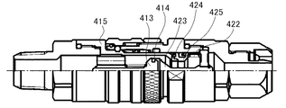
図4は、従来のバルブを有する管継手の構成を示す図である。図4Aは、雄型の継手部材(雄型部材)の断面図である。図4Bは、雌型の継手部材(雌型部材)の断面図である。図4Cは、バルブ450とバルブストップ411の斜視図である。図4Dは、雌型部材と雄型部材を結合した状態を示した図である。
FIG. 4 is a diagram showing a configuration of a pipe joint having a conventional valve. FIG. 4A is a cross-sectional view of a male joint member (male member). FIG. 4B is a cross-sectional view of a female joint member (female member). FIG. 4C is a perspective view of the
図4A,図4Cにおいて、雄型部材410は、雄型部材本体415、アダプタ416、アダプタOリング417、バルブストップ411、バルブスプリング412、バルブ450を有する。バルブ450はバルブ本体413とバルブシール414とを有する。バルブシール414は、材質がゴム等の弾性体であって、筒状のバルブ本体413に取り付けられる。バルブ450は、バルブストップ411に取り付けられたバルブスプリング412で押さえられた状態で、雄型部材本体415に挿入され、アダプタOリング417を装着したアダプタ416で固定される。そして、図4Cに示すように筒状のバルブストップ411は、流体移動用の複数の孔418と、バルブ450の移動の際のガイドとなる孔419を有する。
4A and 4C, the
一方、図4Bに示す雌型の継手部材である雌型部材420は、バルブストップ421、バルブスプリング422、バルブ460、バルブシール閉塞部材(以下、ピントルと称する)423、スナップリング426を有する。バルブ460は、バルブ本体425、バルブシール424、Vシール429を有し、Vシール429は材質がゴム等の弾性体で、バルブ本体425に取り付けられる。バルブ460は、バルブストップ421に取り付けられたバルブスプリング422で押さえられた状態で、ピントル423に当接している。ピントル423は、スナップリング426によりバルブストップ421に固定される。バルブストップ421は、雌型部材本体427とアダプタ428で固定される。
4B includes a
図4Dは、雌型部材420と雄型部材410を結合した状態を示した図である。雌型部材420のピントル423と雄型部材410のバルブシール414、雄型部材410のバルブスプリング412の弾性力で当接し、Vシール425と共に流路内の流体の漏れを防止する。雄型部材本体415の先端部と雌型部材420のバルブシール424は、バルブスプリング422の弾性力で当接し、流路内の流体の漏れを防止する。雌型部材420と雄型部材410を分離する際も、雌型部材420と雄型部材410が完全に離れるまで、前記3つのシール部材で流体の漏れを防止する。
FIG. 4D is a view showing a state in which the
前記雌型部材420と雄型部材410の着脱時の雄型部材側のバルブ450の移動は、バルブストップ411の孔419をガイドにして行っているため、孔419の長さが短いとバルブ450が傾斜して雄型部材本体415に弾接し、漏れが発生する可能性がある。漏れ防止のためにバルブストップ411が長くする必要があるため、圧力損失が大きくなる。
The movement of the
雄型及び雌型の継手部材の一対を接続して、配管を接続する管継手において、バルブ形状を変更する事で圧力損失が小さい管継手を提供する事である。 In a pipe joint that connects a pair of male and female joint members and connects pipes, a pipe joint having a small pressure loss is provided by changing the valve shape.
実施形態の管継手は、筒状着脱部を含む筒状の雄型部材の前記筒状着脱部を雌型部材に挿入して嵌合した様態で、前記筒状着脱部内に内部流体の流路が形成される管継手であって、前記雄型部材および雌型部材は、単体時にばねの弾性により内部流体の漏洩防止状態を保持するバルブを具備し、前記雄型部材の筒状着脱部を前記雌型部材の孔に挿入し嵌合が完了する過程において、前記雄型部材の前記バルブと前記雌型部材とが互いに当接することにより前記雄型部材の前記バルブと前記雌型部材との間での内部流体の漏洩が防止されると共に、雌型部材の前記バルブと前記雄型部材とが互いに当接することにより前記雌型部材の前記バルブと前記雄型部材との間での内部流体の漏洩が防止され、前記雄型部材の前記バルブは、前記雄型部材の内周面にガイドされて前記雄型部材の軸方向に沿って移動可能な3枚以上のフィンを有するバルブ本体と、前記雌型部材側における前記バルブ本体の端部に設けられたバルブシールとを含み、前記3枚以上のフィンは、前記雄型部材の軸方向に沿って配置されるとともに、略全長に亘って前記雄型部材の内周面に摺接可能な状態で前記雄型部材の内周面に摺接してガイドされ、かつ、略全長に亘って前記雄型部材の径方向中心部で放射状に相互に連結され、前記雌型部材とは反対側における前記3枚以上のフィンの端部よりも前記反対側に、前記雄型部材用の前記ばねが配置され、前記バルブシールは、単体時の前記雄型部材において、前記筒状着脱部の先端部内面に当接することにより前記バルブシールと前記筒状着脱部の先端部内面との間での内部流体の漏洩を防止することを特徴とする。 The pipe joint according to the embodiment is configured such that the cylindrical detachable portion of the cylindrical male member including the cylindrical detachable portion is inserted and fitted into the female member, and the flow path of the internal fluid in the cylindrical detachable portion. a pipe joint but formed, the male member and the female member is provided with a valve for holding the leakage prevention state of the internal fluid due to the elasticity of the I if during a single cylindrical attachment and detachment of the male member The valve of the male member and the female member are brought into contact with each other when the valve of the male member and the female member are in contact with each other in the process of inserting the portion into the hole of the female member and completing the fitting. The internal fluid is prevented from leaking between the valve and the male member, and the valve of the female member and the male member are brought into contact with each other. leakage of internal fluid is prevented, the valve of the male member, the male member A valve body having three or more fins which are guided by an inner peripheral surface and movable along the axial direction of the male member; and a valve seal provided at an end of the valve body on the female member side; wherein the said three or more fins, the are arranged along the axial direction of the male member Rutotomoni, the male member in slidable contact state over substantially the entire length to the inner peripheral surface of the male member The three or more fins that are guided in sliding contact with the inner peripheral surface of the member and are radially connected to each other at the radial center of the male member over substantially the entire length thereof. The spring for the male member is disposed on the opposite side of the end of the male member, and the valve seal is in contact with the inner surface of the distal end portion of the cylindrical attachment / detachment portion in the male member as a single unit. The valve seal and the inner surface of the distal end of the cylindrical attachment / detachment portion; Characterized in that to prevent internal leakage of fluid between.
実施形態の管継手によれば、バルブ形状を変更し、バルブストップを無くす事で圧力損失が小さくなる。そして、油圧等の回路中では作動圧力を小さくできる。また、流体輸送の回路では同圧力で流量が大きくなる。更に、継手の材質の一部を樹脂にする事で継手重量が小さくなる。しかも、単体時の雄型部材において、筒状着脱部の先端部を内部流体の漏洩防止状態に保つことができる。 According to the pipe joint of the embodiment, the pressure loss is reduced by changing the valve shape and eliminating the valve stop. In the circuit such as hydraulic pressure, the operating pressure can be reduced. In the fluid transport circuit, the flow rate increases at the same pressure. Furthermore, the joint weight is reduced by using a part of the joint material as a resin. Moreover, in the single male member, the tip of the cylindrical attachment / detachment portion can be kept in a state of preventing leakage of internal fluid.
以下、図面を参照して本発明の実施形態について説明する。
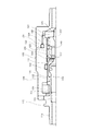
図1は、実施形態の管継手の構成を示す図である。図1Aは、雄型の継手部材(以下、雄型部材と称する)の一部断面図である。図1Bは、雌型の継手部材(以下、雌型部材と称する)の一部断面図である。図1Cは、雄型部材110の有する着脱部品114の先端の段310にバルブシール113が当接する部分の拡大図である。Hereinafter, embodiments of the present invention will be described with reference to the drawings.
Drawing 1 is a figure showing the composition of the pipe joint of an embodiment. FIG. 1A is a partial cross-sectional view of a male joint member (hereinafter referred to as a male member). FIG. 1B is a partial cross-sectional view of a female joint member (hereinafter referred to as a female member). FIG. 1C is an enlarged view of a portion where the
図1A,図1Cにおいて、雄型部材110は、配管取付部品115、着脱部品114、バルブスプリング111、バルブ220、シール材116、段部311などを有している。雄側のバルブ220は、ゴムなどの弾性体であるバルブシール113とバルブ本体112を有している。バルブ220は、配管取付部品115に、バルブスプリング111を圧縮させた状態で内部に装着し、着脱部品114を取り付けている。配管取付部品115と着脱部品114は、配管取付部品のねじ118と着脱部品のねじ119にて取り付けられている。着脱部品114の雌型部材側の端部には、バルブ本体112及びバルブシール113の外径より内径が小さい開口部117を有し、雄型部材先端の段310を有する。そして、バルブ220のバルブシール113は、バルブスプリング111の弾性力により雄型部材先端の段310に漏洩防止状態で当接する。
1A and 1C, the
図1Bは、雌型の雌型部材120の断面図である。雌型部材120は、着脱部品129、配管取付部品128、シール用Oリング132、操作部材(以下、リテーナと称する)130、131、シール用Oリング133、バルブシール閉塞部材(以下、ピントルと称する)127、バルブストップ121、スナップリング123、バルブスプリング122、バルブ140、内部に図示しない雄型部材110の挿入孔を有する。
FIG. 1B is a cross-sectional view of a female
雌側のバルブ140は、バルブ本体124、Vシール125、バルブシール126を有する。バルブ140は、バルブストップ421に取り付けられたバルブスプリング422で押さえられた状態で、ピントル423に当接している。ピントル423は、スナップリング426によりバルブストップ421に固定される。バルブストップ421は、雌型部材本体427とアダプタ428で固定される。バルブ140は、バルブスプリング122の弾性力によりピントル127の裏側に漏洩防止状態で当接する。バルブ本体124と着脱部品129は、Vシール125により漏洩防止状態となる。
The
図2は、雄型部材110のバルブ220の形状を示す図で、筒状のバルブ本体112にバルブシール113を取り付けた状態の図である。図2Aは前記バルブ本体112の斜視図、図2Bはバルブシール113と反対側の軸方向から見た図(バルブシール113側を正面とした場合の背面図)であり、図2Cは軸に対して垂直方向から見た図(平面図)である。
FIG. 2 is a view showing the shape of the
雄側のバルブ220は、バルブ本体112を樹脂材質で一体成形し、バルブ移動時のガイドである少なくとも3枚以上の複数のフィン211を有する事で、移動時にバルブ220の傾斜が発生しにくい。複数のフィン211は、バルブ220の軸上で等角度にあるのが望ましい。図2では、90度ずつ4等分したプラス形状が長手方向に形成された立方体を示したが、これに限定されるものではない。例えば、3等分乃至6等分で構成したフィンであっても良い。バルブ本体112を樹脂成形することで、フィン211の形状が比較的自由な形状とすることができ、圧力損失も小さくなる。
The
図3は、実施形態の雌型部材120と雄型部材110を結合した時の接続図である。
雌型部材120の挿入孔に向けて、雄型部材110の筒状着脱部(図1Aの右端から雄型部材中央部の溝311の左端まで)を挿入するとき、雄側のバルブ220の複数のフィン211が雄型部材110の内周面をガイドにして、スムーズに移動することができる。そして、雄型部材110の先端部が雌型部材120のバルブシール126の位置まで当接すると、同時に雄側のバルブ220のバルブシール113が雌型部材120のピントル127に当接する。さらに、雄型部材110が図3の右側に移動すると、雄型部材110側は、バルブ220がピントル127に押されて、バルブスプリング111が縮み、気密性を保持していたバルブシール113が雄型部材先端の段310から離れて、雄型部材120内に流路が形成される。FIG. 3 is a connection diagram when the
When the cylindrical attachment / detachment portion (from the right end of FIG. 1A to the left end of the
一方、雌型部材120側は、雌側のバルブ140が雄型部材110に押されて、バルブスプリング122が縮み、気密性を保持していたバルブシール126がピントル127から離れて、雌型部材120内にも流路が形成される。
On the other hand, on the
このように本実施形態によれば、雌型部材120のピントル127と雄型部材110のバルブシール113は、雄型部材110のバルブスプリング111の弾性力により漏洩防止状態で当接し、流路内の流体の漏れを防止する。雄型部材本体114の先端部と雌型部材120のバルブシール126は、バルブスプリング122の弾性力により漏洩防止状態で当接し、Vシール125及びシール用Oリング132と共に流路内の流体の漏れを防止する。
As described above, according to the present embodiment, the
雄型部材110と雌型部材120の結合時には、雄型部材110の先端部が雌型部材120のバルブシール126の位置まで当接してバルブスプリング122が縮むと共に、雄型部材110の雄型部材本体114とピントル127に当接してバルブスプリング111が縮むことにより、雄型部材110と雌型部材120間の流路が形成されることになる。そして、その結合を解除すると、雄型部材110と雌型部材120は元の漏洩防止状態に戻る。
When the
なお、雄型部材110と雌型部材120の固定は、樹脂製の部品であるリテーナ130,131(樹脂製操作部材)を雄型部材110の中央部の溝311に嵌合し、リテーナに形成されたばねで押し付けることにより行われる。
実施形態の管継手の形状によれば、バルブストップ411を使用する必要がある従来の形状と比較すると流路面積が大きく、圧力損失が小さくすることができる。The
According to the shape of the pipe joint of the embodiment, the flow path area is large and the pressure loss can be reduced as compared with the conventional shape in which the valve stop 411 needs to be used.
(変形例)
本実施形態のバルブを、図1Aに示す雄型部材の構成でも使用可能である。また、バルブ本体112の材質は、射出成形粉末冶金などで一体成形可能な金属でも良い。さらに、フィン211と別部品に分けて成型し、接着、溶着等で1つの部品にしてもよい。(Modification)
The valve of this embodiment can also be used in the configuration of the male member shown in FIG. 1A. The material of the
本発明のいくつかの実施形態を説明したが、これらの実施形態は、例として提示したものであり、発明の範囲を限定することは意図していない。これら新規な実施形態は、その他の様々な形態で実施されることが可能であり、発明の要旨を逸脱しない範囲で、種々の省略、置き換え、変更を行うことができる。これら実施形態やその変形は、発明の範囲や要旨に含まれるとともに、特許請求の範囲に記載された発明とその均等の範囲に含まれる。 Although several embodiments of the present invention have been described, these embodiments are presented by way of example and are not intended to limit the scope of the invention. These novel embodiments can be implemented in various other forms, and various omissions, replacements, and changes can be made without departing from the scope of the invention. These embodiments and modifications thereof are included in the scope and gist of the invention, and are included in the invention described in the claims and the equivalents thereof.
110 雄型部材
111 バルブスプリング
112 バルブ本体
113 バルブシール
117 開口部
120 雌型部材
121 バルブストップ
122 バルブスプリング
124 バルブ本体
125 Vシール
126 バルブシール
127 バルブシール閉塞部材(ピントル)
128 配管取付部品
130、131 操作部材(リテーナ)
135 バルブ
140 バルブ
211 フィン
220 バルブ
310 雄型部材先端の段
311 雄型部材中央部の溝110
128
135
Claims (3)
前記雄型部材および雌型部材は、単体時にばねの弾性により内部流体の漏洩防止状態を保持するバルブを具備し、
前記雄型部材の筒状着脱部を前記雌型部材の孔に挿入し嵌合が完了する過程において、前記雄型部材の前記バルブと前記雌型部材とが互いに当接することにより前記雄型部材の前記バルブと前記雌型部材との間での内部流体の漏洩が防止されると共に、雌型部材の前記バルブと前記雄型部材とが互いに当接することにより前記雌型部材の前記バルブと前記雄型部材との間での内部流体の漏洩が防止され、
前記雄型部材の前記バルブは、
前記雄型部材の内周面にガイドされて前記雄型部材の軸方向に沿って移動可能な3枚以上のフィンを有するバルブ本体と、
前記雌型部材側における前記バルブ本体の端部に設けられたバルブシールとを含み、
前記3枚以上のフィンは、
前記雄型部材の軸方向に沿って配置されるとともに、略全長に亘って前記雄型部材の内周面に摺接可能な状態で前記雄型部材の内周面に摺接してガイドされ、かつ、略全長に亘って前記雄型部材の径方向中心部で放射状に相互に連結され、
前記雌型部材とは反対側における前記3枚以上のフィンの端部よりも前記反対側に、前記雄型部材用の前記ばねが配置され、
前記バルブシールは、単体時の前記雄型部材において、前記筒状着脱部の先端部内面に当接することにより前記バルブシールと前記筒状着脱部の先端部内面との間での内部流体の漏洩を防止する
ことを特徴とする管継手。 A pipe joint in which a flow path of an internal fluid is formed in the cylindrical attachment / detachment portion in a state in which the cylindrical attachment / detachment portion of a cylindrical male member including the cylindrical attachment / detachment portion is inserted and fitted into a female member. There,
The male member and the female member is provided with a valve for holding the leakage prevention state of the internal fluid due to the elasticity of the I if during alone,
In the process of inserting the cylindrical attachment / detachment portion of the male member into the hole of the female member and completing the fitting, the valve of the male member and the female member come into contact with each other, whereby the male member The internal fluid is prevented from leaking between the valve and the female member of the female member, and the valve of the female member and the male member are brought into contact with each other, whereby the valve of the female member and the female member are brought into contact with each other. leakage of internal fluid between the male member is prevented,
The valve of the male member is
A valve body having three or more fins that are guided by the inner peripheral surface of the male member and are movable along the axial direction of the male member;
A valve seal provided at an end of the valve body on the female member side,
The three or more fins are
Wherein are arranged along the axial direction of the male member Rutotomoni, it is guided in sliding contact with the inner peripheral surface of the male member on the inner peripheral surface of the male member over substantially the entire length slidable contact state, And it is mutually connected radially at the radial center of the male member over substantially the entire length ,
The spring for the male member is disposed on the opposite side of the end of the three or more fins on the opposite side to the female member,
In the male member as a single unit, the valve seal is in contact with the inner surface of the distal end portion of the cylindrical attachment / detachment portion, thereby leaking internal fluid between the valve seal and the inner surface of the distal end portion of the tubular attachment / detachment portion. pipe fitting, characterized in that to prevent.
Applications Claiming Priority (3)
| Application Number | Priority Date | Filing Date | Title |
|---|---|---|---|
| JP2014049800 | 2014-03-13 | ||
| JP2014049800 | 2014-03-13 | ||
| PCT/JP2015/053470 WO2015137027A1 (en) | 2014-03-13 | 2015-02-09 | Pipe joint |
Publications (2)
| Publication Number | Publication Date |
|---|---|
| JPWO2015137027A1 JPWO2015137027A1 (en) | 2017-04-06 |
| JP6236521B2 true JP6236521B2 (en) | 2017-11-22 |
Family
ID=54071479
Family Applications (1)
| Application Number | Title | Priority Date | Filing Date |
|---|---|---|---|
| JP2016507399A Active JP6236521B2 (en) | 2014-03-13 | 2015-02-09 | Pipe fitting |
Country Status (2)
| Country | Link |
|---|---|
| JP (1) | JP6236521B2 (en) |
| WO (1) | WO2015137027A1 (en) |
Families Citing this family (1)
| Publication number | Priority date | Publication date | Assignee | Title |
|---|---|---|---|---|
| TWI820634B (en) | 2022-03-14 | 2023-11-01 | 伍隆國際有限公司 | Fluid joint structure |
Family Cites Families (8)
| Publication number | Priority date | Publication date | Assignee | Title |
|---|---|---|---|---|
| US3035857A (en) * | 1957-10-03 | 1962-05-22 | Floyd M Williamson | Couplings for fluid pressure lines |
| JPS6449791U (en) * | 1987-09-22 | 1989-03-28 | ||
| US4819908A (en) * | 1988-04-12 | 1989-04-11 | Edwards Industries, Inc. | Quick connect fluid coupling |
| JP4245202B2 (en) * | 1998-01-09 | 2009-03-25 | イハラサイエンス株式会社 | Coupler with valve |
| JP3449213B2 (en) * | 1998-03-11 | 2003-09-22 | 株式会社タツノ・メカトロニクス | Safety pipe joint |
| JP2005315420A (en) * | 2004-03-31 | 2005-11-10 | Nabtesco Corp | Joint |
| JP4378647B2 (en) * | 2006-09-20 | 2009-12-09 | Smc株式会社 | Pipe fitting |
| JP2009144785A (en) * | 2007-12-12 | 2009-07-02 | Sanyo Kasei:Kk | Pipe fitting for faucet |
-
2015
- 2015-02-09 JP JP2016507399A patent/JP6236521B2/en active Active
- 2015-02-09 WO PCT/JP2015/053470 patent/WO2015137027A1/en active Application Filing
Also Published As
| Publication number | Publication date |
|---|---|
| JPWO2015137027A1 (en) | 2017-04-06 |
| WO2015137027A1 (en) | 2015-09-17 |
Similar Documents
| Publication | Publication Date | Title |
|---|---|---|
| JP5394460B2 (en) | Fluid coupling | |
| US6681803B2 (en) | Socket and plug attachment mechanism for tube joint | |
| JP6936627B2 (en) | A quick coupling element with a discharge member and a coupling member containing such an element | |
| WO2018138997A1 (en) | Pipe joint | |
| US20070246107A1 (en) | Coupling member of pipe coupling | |
| US8813782B2 (en) | Hydraulic fitting for pipes | |
| JP6484256B2 (en) | Slide valve, female joint member provided with the slide valve, and pipe joint comprising the female joint member and the male joint member | |
| US9772058B2 (en) | Sealed-coupling device without a retention area | |
| JP2006183844A5 (en) | ||
| EP2453156B1 (en) | Pipe joint | |
| JP6236521B2 (en) | Pipe fitting | |
| JP2004257521A (en) | Valve | |
| KR102712264B1 (en) | Pipe Coupling Member | |
| JP5791906B2 (en) | Fluid connector | |
| JP2011075055A (en) | Female joint member for pipe joint | |
| JP2005315420A (en) | Joint | |
| JP6535455B2 (en) | Pipe joint and method of manufacturing pipe joint | |
| JP2019027562A (en) | Pipe joint | |
| JP5116153B2 (en) | Bellows type accumulator | |
| JP2021036163A (en) | Coupling device | |
| JP5579147B2 (en) | Fitting member for pipe fitting | |
| JP4792372B2 (en) | Plug in gas supply connector | |
| JP5967271B2 (en) | Fitting and fitting mounting structure | |
| JP2013231472A (en) | Pipe joint | |
| JP5735024B2 (en) | Pipe fitting |
Legal Events
| Date | Code | Title | Description |
|---|---|---|---|
| A621 | Written request for application examination |
Free format text: JAPANESE INTERMEDIATE CODE: A621 Effective date: 20160406 |
|
| AA64 | Notification of invalidation of claim of internal priority (with term) |
Free format text: JAPANESE INTERMEDIATE CODE: A241764 Effective date: 20160614 |
|
| A521 | Request for written amendment filed |
Free format text: JAPANESE INTERMEDIATE CODE: A523 Effective date: 20160711 |
|
| A131 | Notification of reasons for refusal |
Free format text: JAPANESE INTERMEDIATE CODE: A131 Effective date: 20161115 |
|
| A521 | Request for written amendment filed |
Free format text: JAPANESE INTERMEDIATE CODE: A523 Effective date: 20170106 |
|
| A131 | Notification of reasons for refusal |
Free format text: JAPANESE INTERMEDIATE CODE: A131 Effective date: 20170502 |
|
| A521 | Request for written amendment filed |
Free format text: JAPANESE INTERMEDIATE CODE: A523 Effective date: 20170628 |
|
| TRDD | Decision of grant or rejection written | ||
| A01 | Written decision to grant a patent or to grant a registration (utility model) |
Free format text: JAPANESE INTERMEDIATE CODE: A01 Effective date: 20171010 |
|
| A61 | First payment of annual fees (during grant procedure) |
Free format text: JAPANESE INTERMEDIATE CODE: A61 Effective date: 20171030 |
|
| R150 | Certificate of patent or registration of utility model |
Ref document number: 6236521 Country of ref document: JP Free format text: JAPANESE INTERMEDIATE CODE: R150 |