JP6235801B2 - Stall management system - Google Patents
Stall management system Download PDFInfo
- Publication number
- JP6235801B2 JP6235801B2 JP2013121203A JP2013121203A JP6235801B2 JP 6235801 B2 JP6235801 B2 JP 6235801B2 JP 2013121203 A JP2013121203 A JP 2013121203A JP 2013121203 A JP2013121203 A JP 2013121203A JP 6235801 B2 JP6235801 B2 JP 6235801B2
- Authority
- JP
- Japan
- Prior art keywords
- aircraft
- attack
- alert
- angle
- lift coefficient
- Prior art date
- Legal status (The legal status is an assumption and is not a legal conclusion. Google has not performed a legal analysis and makes no representation as to the accuracy of the status listed.)
- Active
Links
- 238000000034 method Methods 0.000 claims description 53
- 238000010586 diagram Methods 0.000 description 26
- 238000012545 processing Methods 0.000 description 20
- 238000004891 communication Methods 0.000 description 19
- 230000008569 process Effects 0.000 description 18
- RZVHIXYEVGDQDX-UHFFFAOYSA-N 9,10-anthraquinone Chemical compound C1=CC=C2C(=O)C3=CC=CC=C3C(=O)C2=C1 RZVHIXYEVGDQDX-UHFFFAOYSA-N 0.000 description 16
- 230000002085 persistent effect Effects 0.000 description 11
- 230000006870 function Effects 0.000 description 9
- 230000008859 change Effects 0.000 description 7
- 230000004044 response Effects 0.000 description 7
- 230000000007 visual effect Effects 0.000 description 7
- 239000003381 stabilizer Substances 0.000 description 6
- 230000003068 static effect Effects 0.000 description 6
- 230000007613 environmental effect Effects 0.000 description 5
- 238000005259 measurement Methods 0.000 description 5
- 238000012937 correction Methods 0.000 description 4
- 230000007423 decrease Effects 0.000 description 4
- 230000010006 flight Effects 0.000 description 4
- 230000033001 locomotion Effects 0.000 description 4
- 230000004048 modification Effects 0.000 description 4
- 238000012986 modification Methods 0.000 description 4
- 238000003491 array Methods 0.000 description 3
- 230000004397 blinking Effects 0.000 description 3
- 230000003287 optical effect Effects 0.000 description 3
- 230000009471 action Effects 0.000 description 2
- 230000033228 biological regulation Effects 0.000 description 2
- 238000004590 computer program Methods 0.000 description 2
- 230000005540 biological transmission Effects 0.000 description 1
- 238000004364 calculation method Methods 0.000 description 1
- 239000000835 fiber Substances 0.000 description 1
- 239000000446 fuel Substances 0.000 description 1
- 239000002828 fuel tank Substances 0.000 description 1
- 230000005484 gravity Effects 0.000 description 1
- 230000007246 mechanism Effects 0.000 description 1
- 230000000737 periodic effect Effects 0.000 description 1
- 230000000644 propagated effect Effects 0.000 description 1
- 230000002441 reversible effect Effects 0.000 description 1
- 239000004065 semiconductor Substances 0.000 description 1
- 210000003813 thumb Anatomy 0.000 description 1
- 238000012546 transfer Methods 0.000 description 1
- 230000001755 vocal effect Effects 0.000 description 1
Images


Classifications
-
- B—PERFORMING OPERATIONS; TRANSPORTING
- B64—AIRCRAFT; AVIATION; COSMONAUTICS
- B64D—EQUIPMENT FOR FITTING IN OR TO AIRCRAFT; FLIGHT SUITS; PARACHUTES; ARRANGEMENT OR MOUNTING OF POWER PLANTS OR PROPULSION TRANSMISSIONS IN AIRCRAFT
- B64D43/00—Arrangements or adaptations of instruments
- B64D43/02—Arrangements or adaptations of instruments for indicating aircraft speed or stalling conditions
-
- B—PERFORMING OPERATIONS; TRANSPORTING
- B64—AIRCRAFT; AVIATION; COSMONAUTICS
- B64C—AEROPLANES; HELICOPTERS
- B64C13/00—Control systems or transmitting systems for actuating flying-control surfaces, lift-increasing flaps, air brakes, or spoilers
-
- G—PHYSICS
- G05—CONTROLLING; REGULATING
- G05D—SYSTEMS FOR CONTROLLING OR REGULATING NON-ELECTRIC VARIABLES
- G05D1/00—Control of position, course, altitude or attitude of land, water, air or space vehicles, e.g. using automatic pilots
-
- G—PHYSICS
- G05—CONTROLLING; REGULATING
- G05D—SYSTEMS FOR CONTROLLING OR REGULATING NON-ELECTRIC VARIABLES
- G05D1/00—Control of position, course, altitude or attitude of land, water, air or space vehicles, e.g. using automatic pilots
- G05D1/08—Control of attitude, i.e. control of roll, pitch, or yaw
- G05D1/0808—Control of attitude, i.e. control of roll, pitch, or yaw specially adapted for aircraft
- G05D1/0816—Control of attitude, i.e. control of roll, pitch, or yaw specially adapted for aircraft to ensure stability
- G05D1/0825—Control of attitude, i.e. control of roll, pitch, or yaw specially adapted for aircraft to ensure stability using mathematical models
Landscapes
- Engineering & Computer Science (AREA)
- Aviation & Aerospace Engineering (AREA)
- General Physics & Mathematics (AREA)
- Physics & Mathematics (AREA)
- Automation & Control Theory (AREA)
- Remote Sensing (AREA)
- Radar, Positioning & Navigation (AREA)
- Algebra (AREA)
- Mathematical Analysis (AREA)
- Mathematical Optimization (AREA)
- Mathematical Physics (AREA)
- Pure & Applied Mathematics (AREA)
- Traffic Control Systems (AREA)
- Alarm Systems (AREA)
- Emergency Alarm Devices (AREA)
Description
本発明は概して航空機に関し、具体的には航空機の飛行の管理に関する。またさらに具体的には、本発明は、飛行中に航空機が現状において潜在的に失速する可能性がある条件を識別する方法及び装置に関するものである。 The present invention relates generally to aircraft, and more particularly to managing flight of an aircraft. Even more specifically, the present invention relates to a method and apparatus for identifying conditions that may potentially stall an aircraft during flight.
飛行中の航空機の状態は、任意の数の係数によって決まる。これらの係数には、例えば非限定的に、航空機の速度、航空機の大きさ、航空機の形状、航空機の翼の形状、航空機の迎え角、及びその他の種類の係数が含まれる。ある場合には、航空機の操縦機能は、飛行中の航空機の状態の変化に応じて変わる。 The state of the aircraft in flight depends on an arbitrary number of factors. These factors include, for example, without limitation, aircraft speed, aircraft size, aircraft shape, aircraft wing shape, aircraft angle of attack, and other types of factors. In some cases, aircraft maneuvering functions change in response to changes in the state of the aircraft during flight.
例えば、航空機の迎え角が増加して、飛行中に航空機に生じる揚力量が減少すると、航空機は失速する。本明細書で使用する「揚力」とは、飛行中に航空機の上で空気が流れる時に生じる力である。この力は、航空機の重量に直接対抗し、航空機を空中に維持する。 For example, if the angle of attack of the aircraft increases and the amount of lift generated on the aircraft during flight decreases, the aircraft stalls. As used herein, “lift” is the force generated when air flows over an aircraft during flight. This force directly counters the weight of the aircraft and keeps the aircraft in the air.
航空機に生じる揚力が減少するこの特定の迎え角は、航空機の異なる種類によって変化する。航空機が潜在的に失速する可能性のある迎え角は、例えば非限定的に、航空機の翼のプロファイル、翼の平面図、翼のアスペクト比、及び他の係数などの係数に基づいている。さらに、航空機が潜在的に失速する可能性のある迎え角は、航空機の特定の速度に対応する。この速度は「失速速度」と呼ばれる。 This particular angle of attack at which the lift generated on the aircraft decreases varies with different types of aircraft. The angle of attack at which an aircraft can potentially stall is based on factors such as, but not limited to, aircraft wing profile, wing plan view, wing aspect ratio, and other factors. In addition, the angle of attack at which the aircraft can potentially stall corresponds to the specific speed of the aircraft. This speed is called the “stall speed”.
幾つかの現在利用可能な民間航空機では、航空機の速度が若干の選択量だけ失速速度よりも速い警戒速度を下回ったときに、警報が発信される警報システムが使用されている。この警報速度はまた、「最低速度」とも呼ばれる。具体的には、航空機の速度が警報速度よりも遅い時に、警報が発信され、航空機のオペレータは航空機の失速を防止する、又は少なくとも航空機の失速の可能性を低減するような処置を取る。 Some currently available commercial aircraft use alarm systems that issue an alarm when the aircraft speed falls below a warning speed that is faster than the stall speed by some selected amount. This alarm speed is also referred to as the “minimum speed”. Specifically, when the speed of the aircraft is slower than the warning speed, an alarm is issued and the aircraft operator takes action to prevent or at least reduce the possibility of aircraft stall.
航空機の失速速度により、航空機の操縦機能が決定する。例えば、失速速度により、航空機の離陸及び着陸に必要な最低距離が決定する。これらの距離はそれぞれ、航空機の離陸距離及び着陸距離と呼ばれる。航空機の離陸距離及び着陸距離は、航空機が失速せずに離陸中及び着陸中に飛行できる最も遅い速度によって決定される。航空機の離陸速度及び着陸速度は、航空機の警報速度以上である必要がある。 The aircraft's stall speed determines the aircraft's maneuvering function. For example, the stall speed determines the minimum distance required for aircraft takeoff and landing. These distances are called aircraft take-off distance and landing distance, respectively. The take-off and landing distance of an aircraft is determined by the slowest speed at which the aircraft can fly during take-off and landing without stalling. The takeoff speed and landing speed of the aircraft need to be higher than the warning speed of the aircraft.
この結果、航空機の失速速度は、異なる空港での航空機の操縦機能に影響を与える。具体的には、空港において航空機が離陸する滑走路の長さは、少なくとも離陸距離の長さである必要がある。同様に、空港において航空機が着陸する滑走路の長さは、少なくとも着陸速度の長さである必要がある。航空機の離陸距離及び着陸距離はそれぞれ、離陸中及び着陸中の警報速度が低下することにより、短縮される。 As a result, aircraft stall speed affects aircraft maneuverability at different airports. Specifically, the length of the runway from which the aircraft takes off at the airport needs to be at least the length of the take-off distance. Similarly, the length of the runway on which the aircraft lands at the airport needs to be at least the length of the landing speed. The takeoff distance and landing distance of the aircraft are shortened by reducing the alarm speed during takeoff and landing, respectively.
加えて、航空機の失速速度は、異なる荷重倍数に対し、上昇バンク角において機動する航空機の能力に影響を及ぼす。例えば、航空機の旋回半径は、航空機の速度、及び航空機が警報速度を維持している間、及び/または警報速度を上回る間に航空機が飛行できる最大バンク角によって決定する。具体的には、航空機の選択荷重倍数に対して航空機が飛行できる最低機動速度は、選択荷重倍数において警報速度を超えることが要求されるということである。 In addition, aircraft stall speed affects the ability of an aircraft to operate at elevated bank angles for different load multiples. For example, the turning radius of an aircraft is determined by the speed of the aircraft and the maximum bank angle that the aircraft can fly while the aircraft maintains an alarm speed and / or exceeds the alarm speed. Specifically, the minimum maneuvering speed at which the aircraft can fly relative to the selected load multiple of the aircraft is required to exceed the warning speed at the selected load multiple.
航空機の離陸距離及び着陸距離は、連邦航空局によって規定される法規等の様々な法規によって設定される。ある現在使用される警報システムは、警報速度に対して保守的である。例えば、この種の警報システムでは、航空機の操作上の安全性を高めるために、より高い警報速度で警報が発信される。しかしながら、このように高い警報速度によって、ある空港において航空機が操縦不能になる場合がある。したがって、少なくとも上述の問題点の幾つか、並びに起こりうるその他の問題点を考慮に入れた方法及び装置を有することが望ましい。 The take-off distance and landing distance of an aircraft are set according to various regulations such as regulations prescribed by the Federal Aviation Administration. Some currently used alarm systems are conservative with respect to alarm speed. For example, in this type of alarm system, an alarm is transmitted at a higher alarm speed in order to increase operational safety of the aircraft. However, such high alarm speeds may cause the aircraft to become unmanageable at certain airports. Therefore, it would be desirable to have a method and apparatus that takes into account at least some of the issues discussed above, as well as other possible issues.
別の実施形態では、飛行中に航空機を管理する方法が開示されており、この方法は、航空機の事前に識別された警報速度を使用して、航空機の警報迎え角を識別することと、航空機の警報迎え角を使用して、航空機の警報揚力係数を識別することと、航空機の警報揚力係数及び航空機の現在の揚力係数を使用して、航空機の警報速度(246)を識別することとを含む。 In another embodiment, a method for managing an aircraft in flight is disclosed, the method using an aircraft pre-identified alert speed to identify an aircraft alert angle of attack; Using the warning angle of attack of the aircraft to identify the warning lift coefficient of the aircraft and using the warning lift coefficient of the aircraft and the current lift coefficient of the aircraft to identify the warning speed of the aircraft (246) Including.
上記方法は、警報迎え角、警報揚力係数、及び警報速度のうちの少なくとも一つを使用して、航空機の潜在的な失速状態を示す警報を発信するために使用する一組の閾値を識別することを含む。 The method uses at least one of an alert angle of attack, an alert lift coefficient, and an alert speed to identify a set of thresholds used to emit an alert that indicates a potential stall condition of the aircraft. Including that.
上記方法において、航空機の潜在的な失速状態を示す警報を発信するために使用する一組の閾値を識別するステップは、警報迎え角を使用した迎え角閾値、警報揚力係数を使用した揚力係数閾値、及び警報速度を使用した速度閾値のうちの少なくとも一つを識別することを含む。 In the above method, the step of identifying a set of threshold values used to issue an alarm indicating a potential stall condition of the aircraft includes: an attack angle threshold using an alert angle of attack; a lift coefficient threshold using an alarm lift coefficient And identifying at least one of the speed thresholds using the alarm speed.
上記方法は、航空機の迎え角のうちの少なくとも一つが迎え角閾値を上回る時、航空機の現在の揚力係数が揚力係数閾値を上回る時、また航空機の速度が速度閾値を下回る時に警報を発信し、この警報を航空機のスティックシェイカーへ送ることを含む。 The method issues an alarm when at least one of the aircraft attack angles is above the attack angle threshold, when the aircraft current lift coefficient is above the lift coefficient threshold, and when the aircraft speed is below the speed threshold, Including sending this alert to an aircraft stick shaker.
上記方法において、航空機の事前に識別された警報速度を使用して航空機の警報迎え角を識別するステップは、フラップのデテント位置と表を使用して初期の警報迎え角を識別することと、航空機の事前に識別された警報速度を使用してマッハ補償バイアスを識別することと、初期の警報迎え角とマッハ補償バイアスを使用して航空機の警報迎え角を識別することとを含む。 In the above method, identifying the aircraft alert angle of attack using the aircraft's pre-identified alert speed comprises identifying the initial alert angle of attack using the flap detent position and table; Identifying the Mach compensation bias using a pre-identified alert speed and identifying the aircraft alert attack angle using the initial alert attack angle and the Mach compensation bias.
上記方法において、初期の警報迎え角とマッハ補償バイアスを使用して航空機の警報迎え角を識別するステップは、初期の警報迎え角、マッハ補償バイアス、及び現在の翼荷重バイアスと、速度ブレーキ補償バイアスと、迎え角バイアスのうちの少なくとも一つを使用して航空機の警報迎え角を識別することを含む。 In the above method, identifying the aircraft warning angle of attack using the initial warning angle of attack and the Mach compensation bias includes initial warning angle of attack, Mach compensation bias, current wing load bias, and speed brake compensation bias. And using at least one of the angle-of-attack bias to identify the warning angle of attack of the aircraft.
上記方法において、航空機の警報迎え角を使用して航空機の警報揚力係数を識別するステップは、航空機の警報迎え角、フラップのデテント位置、及び表を使用して航空機の警報揚力係数を識別することを含む。 In the above method, the step of identifying the aircraft alert lift coefficient using the aircraft alert angle of attack identifies the aircraft alert lift coefficient using the aircraft alert angle of attack, the flap detent position, and the table. including.
上記方法において、航空機の警報揚力係数と、航空機の現在の揚力係数を使用して航空機の警報速度を識別するステップは、修正迎え角、フラップのデテント位置、及び表を使用して航空機の現在の揚力係数を識別することと、現在の揚力係数を警報揚力係数で割って、揚力因数を求めることと、揚力因数の平方根を識別して速度因数を求めることと、航空機の速度因数と現在の速度を使用して警報速度を識別することとを含み、警報速度とは、航空機の警報マッハであり、現在の速度は航空機の現在のマッハである。 In the above method, identifying the aircraft alert speed using the aircraft alert lift coefficient and the aircraft current lift coefficient comprises using the modified angle of attack, the flap detent position, and the table Identify the lift coefficient, divide the current lift coefficient by the warning lift coefficient to determine the lift factor, identify the square root of the lift factor to determine the speed factor, the aircraft speed factor and the current speed To identify the alert speed, where the alert speed is the aircraft alert Mach and the current speed is the aircraft current Mach.
上記方法において、航空機の警報迎え角を使用して航空機の警報揚力係数を識別するステップは、航空機の警報迎え角を使用して航空機の警報揚力係数を識別することを含み、警報揚力係数は、航空機の現在の失速揚力係数よりも実質的に選択された割合だけ小さい。 In the above method, identifying the aircraft alert lift coefficient using the aircraft alert angle of attack includes identifying the aircraft alert lift coefficient using the aircraft alert angle of attack, wherein the alert lift coefficient is: It is substantially less than a selected percentage of the aircraft's current stall lift coefficient.
上記方法において、航空機の事前に識別された警報速度を使用して航空機の警報迎え角を識別し、航空機の警報迎え角を使用して航空機の警報揚力係数を識別し、航空機の警報揚力係数と航空機の現在の揚力係数を使用して航空機の警報速度を識別するステップは、航空機の機動飛行のために行われる。 In the above method, the aircraft's pre-identified alert speed is used to identify the aircraft's alert angle of attack, the aircraft's alert angle of attack is used to identify the aircraft's alert lift coefficient, and the aircraft's alert lift coefficient and The step of identifying the alert speed of the aircraft using the aircraft's current lift coefficient is performed for the aircraft's maneuver flight.
別の実施形態では、飛行中の航空機の潜在的な失速状態を示す方法が開示されており、この方法は、航空機の警報揚力係数を識別し、航空機の現在の状態の任意の数の変化に応じて警報揚力係数を調節することと、警報揚力係数を使用して航空機が潜在的な失速状態に陥ったことを示す警報を発信するのに使用される一組の閾値を識別することとを含む。 In another embodiment, a method for indicating a potential stall condition of an aircraft in flight is disclosed, the method identifying an aircraft warning lift coefficient and detecting any number of changes in the current state of the aircraft. Adjusting the alert lift coefficient accordingly, and using the alert lift coefficient to identify a set of thresholds used to issue an alert indicating that the aircraft has entered a potential stall condition. Including.
警報の発信を含む上記方法において、この警報は、触覚警報、視覚警報、聴覚警報、及びメッセージのうちの少なくとも一つを含む。 In the above method including sending an alert, the alert includes at least one of a tactile alert, a visual alert, an audible alert, and a message.
さらに別の実施形態では、失速管理システムが開示されており、このシステムは、航空機の事前に識別された警報速度を使用して航空機の警報迎え角を識別し、航空機の警報迎え角を使用して航空機の警報揚力係数を識別し、航空機の警報揚力係数と、航空機の現在の揚力係数を使用して航空機の警報速度を識別するように構成された閾値生成器を備える。 In yet another embodiment, a stall management system is disclosed that uses an aircraft pre-identified alert speed to identify an aircraft alert angle of attack and uses the aircraft alert angle of attack. A threshold generator configured to identify the aircraft alert lift coefficient and to identify the aircraft alert speed using the aircraft alert lift coefficient and the aircraft current lift coefficient.
上記失速管理システムにおいて、閾値生成器は、警報迎え角、警報揚力係数、及び警報速度のうちの少なくとも一つを使用して航空機の潜在的な失速状態を示す警報を発信するのに使用される一組の閾値を識別するように構成されている。 In the stall management system, the threshold generator is used to issue an alert indicating a potential stall condition of the aircraft using at least one of an alert angle of attack, an alert lift coefficient, and an alert speed. It is configured to identify a set of threshold values.
上記失速管理システムにおいて、閾値生成器は、警報迎え角を使用した迎え角閾値、警報揚力係数を使用した揚力係数閾値、及び警報速度を使用した速度閾値のうちの少なくとも一つを識別することによって、航空機の潜在的な失速状態を示す警報を発信するのに使用される一組の閾値を識別するように構成されている。 In the stall management system, the threshold generator identifies at least one of an attack angle threshold using an alert angle of attack, a lift coefficient threshold using an alarm lift coefficient, and a speed threshold using an alarm speed. , Configured to identify a set of threshold values used to emit an alert indicating a potential stall condition of the aircraft.
上記失速管理システムはさらに、閾値生成器から一組の閾値を受け取り、航空機の迎え角が迎え角閾値を上回る、航空機の現在の揚力係数が揚力係数閾値を上回る、航空機の速度が速度閾値を下回ることのうちの少なくとも一つが起きた時に、警報を発信し、この警報を航空機のスティックシェイカーに送るように構成された警報発信器を含む。 The stall management system further receives a set of thresholds from the threshold generator, the aircraft angle of attack is above the angle of attack threshold, the aircraft's current lift coefficient is above the lift coefficient threshold, and the speed of the aircraft is below the speed threshold It includes an alarm transmitter configured to emit an alarm and send the alarm to an aircraft stick shaker when at least one of the events occurs.
上記失速管理システムにおいて、閾値生成器は、フラップのデテント位置と任意の数の表のうちの一つの表を使用して初期の警報迎え角を識別することによって警報迎え角を識別し、航空機の事前に識別された警報速度を使用してマッハ補償バイアスを識別し、初期の警報迎え角とマッハ補償バイアスを使用して航空機の警報迎え角を識別するように構成されている。 In the stall management system, the threshold generator identifies the warning angle of attack by identifying the initial warning angle of attack using one of the flap detent positions and any number of tables, and A pre-identified alert speed is used to identify the Mach compensation bias, and the initial alert angle of attack and the Mach compensation bias are used to identify the aircraft alert angle of attack.
上記失速管理システムにおいて、閾値生成器は、初期の警報迎え角、マッハ補償バイアス、及び現在の翼荷重バイアス、速度ブレーキ補償バイアス、及び迎え角バイアスのうちの少なくとも一つを使用して航空機の警報迎え角を識別することによって、航空機の警報迎え角を識別するように構成されている。 In the stall management system, the threshold generator uses an initial warning angle of attack, Mach compensation bias, and at least one of the current wing load bias, speed brake compensation bias, and angle of attack bias to alert the aircraft. The aircraft is configured to identify the warning angle of attack of the aircraft by identifying the angle of attack.
上記失速管理システムにおいて、閾値生成器は、航空機の警報迎え角、フラップのデテント位置、及び表を使用して航空機の警報揚力係数を識別するように構成されている。 In the stall management system, the threshold generator is configured to identify an aircraft alert lift coefficient using an aircraft alert angle of attack, a flap detent position, and a table.
上記失速管理システムにおいて、閾値生成器はさらに、航空機の機動飛行のために、航空機の事前に識別された警報速度を使用して航空機の警報迎え角を識別し、航空機の警報迎え角を使用して航空機の警報揚力係数を識別し、航空機の警報揚力係数と航空機の現在の揚力係数を使用して航空機の警報速度を識別するステップを行うように構成されている。 In the stall management system, the threshold generator further identifies the aircraft alert angle of attack using the aircraft's pre-identified alert speed and uses the aircraft alert angle of attack for maneuvering of the aircraft. Identifying an aircraft alert lift coefficient and identifying the aircraft alert speed using the aircraft alert lift coefficient and the aircraft current lift coefficient.
特徴、及び機能は、本発明の様々な実施形態で独立に実現することが可能であるか、以下の説明及び図面を参照してさらなる詳細が理解されうる、さらに別の実施形態で組み合わせることが可能である。 The features and functions may be implemented independently in various embodiments of the present invention or may be combined in yet other embodiments, which may be further understood with reference to the following description and drawings. Is possible.
例示的な実施形態の特徴と考えられる新規の機能は、添付の特許請求の範囲に明記される。しかしながら、実施形態と、好ましい使用モードと、さらにはその目的と利点は、添付図面を参照して本発明の一実施形態の以下の詳細な説明を読むことにより最もよく理解されるであろう。 The novel features believed characteristic of the exemplary embodiments are set forth in the appended claims. However, the embodiments, preferred modes of use, as well as their objects and advantages, will be best understood by reading the following detailed description of one embodiment of the invention with reference to the accompanying drawings.
実施形態は、一又は複数の検討事項を認識し、且つ考慮している。例えば、実施形態は、いくつかの現在利用可能な警報システムにおいて、警報を発信するのに使用される警報速度が、航空機に生じる揚力が飛行中に実質的に一定のまま保たれるという仮定に基づくものであることを認識し、考慮している。つまり、航空機の警報速度を識別するために、固定の警報揚力係数が使用される。この固定の警報揚力係数は、航空機の予測される失速揚力係数よりもある選択量だけ小さい。しかしながら、実施形態は、航空機の実際の揚力係数が、航空機の状態が飛行中に変化した時に変化することを認識し、考慮している。さらに、航空機の失速速度は、航空機の揚力係数が変化したときに変化する。 Embodiments recognize and take into account one or more considerations. For example, in some currently available alarm systems, the alert speed used to issue the alarm assumes that the lift generated on the aircraft remains substantially constant during the flight. Recognize and consider that it is based. That is, a fixed warning lift coefficient is used to identify the warning speed of the aircraft. This fixed warning lift coefficient is a selected amount less than the aircraft's predicted stall lift coefficient. However, embodiments recognize and take into account that the actual lift coefficient of the aircraft changes when the aircraft's condition changes during flight. In addition, the stall speed of the aircraft changes when the lift coefficient of the aircraft changes.
例えば、選択された迎え角の揚力係数は、航空機のマッハ数が増加すると小さくなる。本明細書で使用する航空機のマッハ数とは、空中を飛ぶ航空機の速度を局所音速で割ったものである。航空機のマッハ数は、航空機周囲の空気の状態に基づいて変化する。これらの状態は例えば、気温及び/又は気圧を含む。 For example, the lift coefficient of the selected angle of attack decreases as the aircraft's Mach number increases. As used herein, the Mach number of an aircraft is the speed of an aircraft flying in the air divided by the local sound velocity. An aircraft's Mach number varies based on the air conditions around the aircraft. These conditions include, for example, temperature and / or pressure.
実施形態は、いくつかの現在利用可能な警報システムによって使用される固定の警報揚力係数が、離陸及び着陸に必要な速度よりも高い警報速度に対応することを認識し、考慮している。さらに、実施形態は、飛行中のある場合において、固定の警報揚力係数を使用して識別された警報速度が、航空機の失速速度よりも低いことを認識し、考慮している。この結果、航空機がその航空機の失速速度に到達する前に警報が発信されない。この警報がないと、航空機のオペレータは、任務を遂行するのに必要な機動飛行を行っている間に気づかずに、航空機を失速させてしまう可能性がある。 Embodiments recognize and take into account that the fixed warning lift coefficient used by some currently available warning systems corresponds to higher warning speeds than are required for takeoff and landing. Furthermore, embodiments recognize and take into account that, in some cases during flight, the alert speed identified using a fixed alert lift coefficient is lower than the stall speed of the aircraft. As a result, no alert is issued before the aircraft reaches its stall speed. Without this warning, the aircraft operator may stall the aircraft without noticing while performing the maneuver required to perform the mission.
加えて、異なる実施形態は、いくつかの現在利用される警報システムが、航空機の迎え角に基づいて警報を発信することを認識し、考慮している。例えば、これらの警報システムは、航空機の迎え角が警報迎え角よりも大きい時に警報を発信する。実施形態は、これらの現在使用される警報システムによって使用される警報迎え角では、航空機の失速揚力係数及び/又は航空機の状態の変化が考慮されていないことを認識し、考慮している。 In addition, the different embodiments recognize and take into account that some currently utilized alarm systems emit alarms based on the angle of attack of the aircraft. For example, these alarm systems issue an alarm when the angle of attack of the aircraft is greater than the alarm angle of attack. The embodiments recognize and take into account that the warning angle of attack used by these currently used warning systems does not take into account changes in aircraft stall lift coefficient and / or aircraft conditions.
したがって、実施形態は、所望の精度で航空機の警報速度を識別する方法及び装置を提供する。具体的には、異なる実施形態は、航空機の状態の変化に応じて変化する航空機の警報揚力係数に基づいて航空機の警報速度を識別するように構成された失速管理システムを提供する。一実施形態では、航空機の飛行を管理する方法が提供される。航空機の警報迎え角は、航空機のフィードバック警報速度を使用して識別される。警報揚力係数は、警報迎え角を使用して識別される。航空機の警報速度は、警報揚力係数及び航空機の修正揚力係数を使用して計算される。警報速度は、警報迎え角を識別する時にフィードバック警報速度として使用される。 Accordingly, embodiments provide a method and apparatus for identifying an aircraft alert speed with a desired accuracy. In particular, the different embodiments provide a stall management system configured to identify an aircraft alert speed based on an aircraft alert lift coefficient that varies in response to changes in aircraft conditions. In one embodiment, a method for managing flight of an aircraft is provided. The aircraft alert angle of attack is identified using the aircraft feedback alert speed. The alert lift coefficient is identified using the alert angle of attack. The aircraft alert speed is calculated using the alert lift coefficient and the modified lift coefficient of the aircraft. The alert speed is used as a feedback alert speed when identifying the alert angle of attack.
ここで図面を参照する。具体的に図1を参照すると、図1には一実施形態による航空機が示されている。この実施例では、航空機100は、機体106に取り付けられた翼102、及び翼104を有する。航空機100は、翼102に取り付けられたエンジン108と、翼104に取り付けられたエンジン110を含む。機体106は尾部112を有する。水平安定板114、水平安定板116、及び垂直安定板118は機体106の尾部112に取り付けられる。
Reference is now made to the drawings. Referring specifically to FIG. 1, FIG. 1 shows an aircraft according to one embodiment. In this illustrative example,
航空機100は、一実施形態において失速管理システムが実装可能な航空機の一例である。失速管理システムは、航空機の状態の変化に応じて変化する航空機の警報速度を識別するために使用される。具体的には、失速管理システムは、飛行中の航空機の状態の変化に基づいて変化する揚力係数を使用する。この結果、この失速管理システムは、飛行中の航空機の状態の変化を考慮に入れた警報速度を識別し、常に航空機の失速速度を超える速度を保つことができる。
さらに、可変の警報揚力係数を使用する場合、固定の警報揚力係数を使用して識別される警報速度よりも保守的でない警報速度が識別される。つまり、可変の警報揚力係数を使用して識別される警報速度は、固定の警報揚力係数を使用して識別される警報速度よりも低い。この結果、航空機の操縦機能が向上する。具体的には、オペレータが、警報を受け取る前により多くの航空機の機動飛行を行うことができる。加えて、航空機が必要とする離陸距離及び着陸距離が短縮されるため、航空機はより多くの数の空港において操作可能となる。 Further, when using a variable alert lift coefficient, alert speeds that are less conservative than those identified using a fixed alert lift coefficient are identified. That is, the alarm speed identified using a variable alarm lift coefficient is lower than the alarm speed identified using a fixed alarm lift coefficient. As a result, the aircraft maneuvering function is improved. Specifically, the operator can fly more aircraft before receiving an alarm. In addition, the aircraft can be operated at a greater number of airports because the take-off and landing distances required by the aircraft are reduced.
ここで図2を参照する。図2は、一実施形態による航空機環境における航空機のブロック図である。この実施例では、航空機環境200は航空機202を含む。図1の航空機100は、図2にブロック図の形式で示した航空機202の一実装例である。
Reference is now made to FIG. FIG. 2 is a block diagram of an aircraft in an aircraft environment according to one embodiment. In this illustrative example,
図示したように、航空機202は空中205を飛行中に揚力204を発生させる。揚力204は、航空機202の飛行中に任意の数の因数206の影響を受ける。本明細書で使用している「任意の数のアイテム」は、一又は複数のアイテムを意味する。たとえば、任意の数の因数206は、一又は複数の揚力因数である。任意の数の因数206は、任意の数の航空機因数208、任意の数の動的係数210、及び任意の数の環境因数212のうちの少なくとも一つを含む。
As shown, the
本明細書において、列挙されたアイテムと共に使用される「〜のうちの少なくとも1つ」という表現は、列挙されたアイテムの一又は複数の様々な組み合わせが使用可能であり、且つ列挙された各アイテムのうちの一つだけあればよいということを意味する。例えば、「アイテムA、アイテムB、及びアイテムCのうちの少なくとも1つ」は、例えば、限定しないが、「アイテムA」、又は「アイテムAとアイテムB」を含む。この例は、「アイテムAとアイテムBとアイテムC」、又は「アイテムBとアイテムC」も含む。他の例として、「〜のうちの少なくとも1つ」は、例えば、限定しないが、「2個のアイテムAと1個のアイテムBと10個のアイテムC」、「4個のアイテムBと7個のアイテムC」、並びに他の適切な組み合わせを含む。 As used herein, the expression “at least one of” used with the listed items can be used in various combinations of one or more of the listed items, and each listed item. Means that only one of For example, “at least one of item A, item B, and item C” includes, for example, without limitation, “item A” or “item A and item B”. This example also includes “item A and item B and item C” or “item B and item C”. As another example, “at least one of” is, for example, without limitation, “two items A, one item B, and ten items C”, “four items B and 7”. Item C ”as well as other suitable combinations.
任意の数の航空機因数208は、航空機202の大きさ及び/又は形状に関連する一又は複数の因数を含む。任意の数の動的因数210は、空中205を飛ぶ航空機202の動きに関連する一又は複数の因数を含む。さらに、任意の数の環境因数212は、空気205に関連する一又は複数の因数を含む。
Any number of
これらの実施例では、航空機202は、センサシステム214と失速管理システム216を備える。センサシステム214は任意の数の因数206を監視するように構成されており、失速管理システム216は、任意の数の因数206に基づいて、航空機202の飛行中に望ましくない状況が起こりうることを航空機202のオペレータ217に警告するように構成されている。
In these illustrative examples,
図示のように、センサシステム214は任意の数のセンサ218を備える。任意の数のセンサ218は、例えば非限定的に、迎え角インジケータ、位置センサ、温度センサ、運動センサ、及び他の好適な種類のセンサのうちの少なくとも一つを備える。
As shown, the
任意の数のセンサ218は、任意の数の因数206の少なくとも一部のデータ220を生成するように構成されている。データ220は、例えば非限定的に、任意の数の因数206の値を含む。ある場合には、データ220の少なくとも一部が継続的にほぼリアルタイムで生成される。他の実施例では、データ220の一部は特定の時間間隔で生成される。
Any number of
失速管理システム216は、センサシステム214からデータ220を受け取るように構成されている。失速管理システム216は、データ220を使用して航空機202の飛行の限界を識別し、これにより飛行中に航空機202が失速する可能性を低減するように構成されている。
これらの実施例では、失速管理システム216は、ハードウェア、ソフトウェア、又はその二つの組み合わせを使用して実施することができる。たとえば、失速管理システム216は、コンピュータシステム222で実行される。コンピュータシステム222は、一又は複数のコンピュータを備える。複数のコンピュータが存在する場合には、これらのコンピュータは例えばネットワークなどの通信媒体を使用して相互に通信することができる。
In these illustrative examples,
図示したように、失速管理システム216は、閾値生成器224及び警報発信器226を備える。これらの実施例では、閾値生成器224は、センサシステム214から受け取ったデータ220を使用して一組の閾値228を生成するように構成される。本明細書で使用する「一組の」アイテムは、一又は複数のアイテムを意味する。例えば、「一組の閾値228」は、1つ又は複数の警報閾値を含む。警報発信器226は、一組の閾値228のうちの一又は複数の閾値が交差した時に、警報230を発信する。
As illustrated, the
これらの実施例では、一組の閾値228は、迎え角閾値231、揚力係数閾値232、及び速度閾値234のうちの少なくとも一つを含む。迎え角閾値231とは、航空機202の臨界迎え角よりもある選択量だけ小さい迎え角である。臨界迎え角とは、飛行中の航空機202の現状において航空機202が失速する迎え角である。
In these illustrative examples, the set of threshold values 228 includes at least one of an attack
揚力係数閾値232とは、航空機202の失速揚力係数よりもある選択量だけ小さい揚力係数である。失速揚力係数とは、飛行中の航空機202の現状において航空機202が失速する揚力係数である。
さらに、速度閾値234とは、航空機202の失速速度よりも速い速度である。失速速度とは、航空機202の現状において航空機202が失速する速度である。速度閾値234は、任意の数の異なる方法で表される。例えば、速度閾値234は、ノット、時速マイル、マッハ数、又はその他何らかの種類の速度表示によって表される。
Further, the
一組の閾値228は、任意の数の異なる方法で生成される。一実施例では、閾値生成器224はデータ220を使用して、迎え角236と翼の形状238を識別する。本明細書で使用する迎え角236とは、航空機202の翼の翼弦線と、航空機202と空気205との間の相対運動を表すベクトルとの間の角度である。本明細書で使用する翼の翼弦線とは、翼の後縁と、翼形状238の断面の前縁の曲線の中央との間の仮想の直線である。
The set of threshold values 228 is generated in any number of different ways. In one embodiment,
これらの実施例では、翼形状238は「エーロフォイル」又は「翼形態」とも呼ばれる。翼形状238は、航空機202の翼の形状、及び翼に取り付けられた全てのフラップ、スラット、及び/又は他の操縦面の形状を含む。
In these examples, the
閾値生成器224は、迎え角236と翼形状238を使用して、航空機202の揚力係数240を識別する。揚力係数240とは、航空機202の現在の揚力係数である。さらに、閾値生成器224は翼形状238と警報迎え角242と使用して、警報揚力係数244を識別する。警報迎え角242は、フィードバック248を使用して閾値生成器224によって識別される。
ある実施例では、警報揚力係数244は、警報揚力係数244が常に、航空機202の現在の失速揚力係数よりも実質的に選択割合だけ小さくなるように識別される。ある場合には、この選択割合は約5%、10%、又はその他何らかの選択割合である。このように、航空機202の失速揚力係数が航空機202の状態の変化に基づいて変化する時、揚力係数閾値232も変化する。
In certain embodiments, the
この実施例では、警報揚力係数244と揚力係数240を使用して、警報速度246が識別される。警報速度246は、次の警報迎え角242を識別するためのフィードバック248として使用される。次の警報迎え角242とは、現時点よりも後の時点の航空機202の迎え角である。この結果、警報迎え角242を識別するのに使用されるフィードバック248は、この実施例では事前に識別された警報速度246である。この方法において、警報迎え角242と警報揚力係数244は、飛行中の航空機202の現在の状態の任意の数の変化に基づいて調節される。これらの変化には、任意の数の因数206のうちの一又は複数の変化が含まれる。
In this example,
ある実施例では、警報速度246は、航空機202の特定の機動飛行に対して識別される。例えば、警報速度246は、航空機202が約0度よりも大きいバンク角で飛行する航空機202の旋回機動飛行に対して識別される。この警報速度は、実質的に水平飛行中の航空機202の警報速度とは異なる場合がある。
In certain embodiments, the
閾値生成器224は、任意の数のデータ構造250及び/又はモデル252を使用して、揚力係数240、警報迎え角242、警報揚力係数244、警報速度246、及び/又は他の種類のパラメータを識別する。任意の数のデータ構造250は、例えば非限定的に、任意の数の表251の形態である。当然ながら、他の実施例では、任意の数のデータ構造250のうちの一つのデータ構造は、データベース、表、フラットファイル、リンクリスト、スプレッドシート、モデル、連想メモリ、又はその他何らかの好適な種類のデータ構造のうちの少なくとも一つを含む。モデル252は、例えば非限定的に、任意の数の数式、アルゴリズム、及び/又はこれらのパラメータの値を計算するプロセスを含む。
The
閾値生成器224は、警報迎え角242、警報揚力係数244、及び警報速度246のうちの少なくとも1つをそれぞれ、迎え角閾値231、揚力係数閾値232、及び速度閾値234として使用して、一組の閾値228を形成する。閾値生成器224は、一組の閾値228を警報発信器226へ送る。
The
実装形態によっては、閾値生成器224は、周期的事象及び/又は非周期的事象の発生に応じて、航空機202の飛行中に連続的に一組の閾値228を発生させる。さらに、一組の閾値228は、任意の数の因数206に対する飛行中の航空機202の状態の変化を考慮に入れている。加えて、一組の閾値228は、航空機202によって行われる例えば旋回等の操縦を考慮に入れている。このように、一組の閾値228は、飛行中の航空機202に対して動的に識別される。
In some implementations,
警報発信器226は、一組の閾値228の迎え角閾値231、揚力係数閾値232、及び速度閾値234のうちの少なくとも1つを使用して、警報230を形成する。これらの実施例では、警報230は、視覚警報、聴覚警報、触覚警報、及びその他何らかの種類の警報のうちの少なくとも1つの形態である。警報230は、潜在的な失速状態256を示す。具体的には、警報230は、航空機202が潜在的な失速状態256に陥ったことを示すものである。航空機202が潜在的な失速状態256に陥ると、航空機202は失速に近い状態である。例えば、航空機202が潜在的な失速状態256にある時に、航空機202は、航空機202の臨界迎え角、失速揚力係数、及び/又は失速速度のうちの少なくとも1つに近づいている。
警報230は、航空機202のオペレータ217に検出されるような方法で発信される。航空機202のオペレータ217は、航空機202が失速することを防止する、又は航空機202が失速する可能性を低減するために任意の数の機動飛行を行う。
この方法において、実施形態は、航空機202の飛行を管理するシステムを提供する。具体的には、失速管理システム216により、潜在的な失速状態256を示すいくつかの現在利用可能な失速管理システムと比べてより正確な警報230を航空機202のオペレータ217に提示することが可能になる。さらに、失速管理システム216により、航空機202が飛行できる速度範囲が広がる、航空機202によって実施される機動飛行の数が増える、又は航空機202が飛行できる速度範囲の拡大、及び航空機202によって実施される機動飛行の数の増加の両方が実現される。速度範囲及び機動飛行のうちの少なくとも一つのこの拡大又は増加は、航空機202の現在の状態に基づいて警報230を発信するための一組の閾値228をアップデートすることによって可能になる。
In this manner, embodiments provide a system for managing the flight of
次に図3を参照する。図3は、一実施形態による、航空機202に生じる揚力204に影響を与える任意の数の因数206を示すブロック図である。図示したように、任意の数の因数206には、任意の数の航空機因数208、任意の数の動的因数210、及び任意の数の環境因数212が含まれる。
Reference is now made to FIG. FIG. 3 is a block diagram illustrating an arbitrary number of
これらの実施例では、任意の数の航空機因数208には、重量302、迎え角304、翼の形状306、バンク角308、標準の荷重倍数310、及び任意の数の外部ストア312のうちの少なくとも一つが含まれる。最初に、重量302は離陸時における図2の航空機202の総重量である。重量302は、航空機202の飛行が進むにつれて変化する。例えば、重量302は、飛行中の燃料の消費によって変化する。
In these illustrative examples, any number of
迎え角304は、航空機202の翼の翼弦線間の角度であり、ベクトルは図2の航空機202と空気205との間の相対運動を表す。迎え角304についてのデータ220は、航空機202の一又は複数の迎え角ベーンから測定された一又は複数の測定値を含む。図2の閾値生成器224はこれらの測定値を使用して、図2の迎え角236を計算する。例えば、閾値生成器224は、航空機202のこれらの迎え角ベーンから重心までの距離に基づいて、一又は複数の迎え角ベーンによって示された測定値に対する修正を行う。この方法において、図2の迎え角236は、修正迎え角である。
The angle of
これらの実施例では、航空機202の翼の形状306は、例えば非限定的に、航空機202の一又は複数の翼に取り付けられた操縦面314の位置に基づくものである。これらの翼に取り付けられた操縦面には、例えばフラップ、スラット、及び/又はその他好適な種類の操縦面が含まれる。ある実施例では、航空機202の翼の形状306は、フラップの位置315及びスラットの位置316のうちの少なくとも一つに基づくものである。フラップの位置315は、航空機202上の翼のフラップの位置である。スラットの位置316は、航空機202上のスラットの位置である。
In these illustrative examples, the
バンク角308とは、航空機202の経路に対して、航空機202の胴体を貫く縦軸周囲で傾斜する航空機202の角度である。標準の荷重倍数310とは、航空機202の垂直荷重であり、gの単位で測定される。任意の数の外部ストア312とは、揚力204の変化の原因となる、翼、胴体、又は航空機202の他の何らかの部分に取り付けられた一又は複数の構成要素である。これらの構成要素には、例えば非限定的に、外部燃料タンク、補助タンク、パイロン、及びその他何らかの種類の構成要素のうちの少なくとも一つが含まれる。
The
図示したように、任意の数の動的因数210には速度318が含まれる。速度318は、例えばマッハ数320、真対気速度322、及び較正対気速度324のうちの少なくとも一つとして表される。当然ながら、他の実施例では、速度318は、指示対気速度、等価対気速度、又は他の何らかの速度測定値として表すことができる。
As shown, any number of
任意の数の環境因数212には、気温326、静圧328、及びラム気圧330のうちの少なくとも一つが含まれる。気温326とは、航空機202の外の空気205の温度である。静圧328とは、航空機202のピトー静圧管又はフラッシュ静圧管等のデバイスのポート内で測定される圧力である。ラム気圧330とは、航空機202のピトー静圧管の中に流れ込む空気205によって生じる圧力である。
The arbitrary number of
図3に示す因数は、航空機202によって生じる揚力204に影響を与える任意の数の因数206のうちのいくつかの種類の因数の例に過ぎない。これらの実施例は、揚力204に影響を与える因数及び/又は図2の失速管理システム216によって考慮される因数を限定する、又は特定するものではない。
The factors shown in FIG. 3 are only examples of some types of factors out of any number of
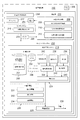
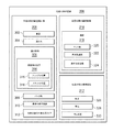
次に図4を参照する。図4は、一実施形態による、飛行制御システムに実装される失速管理システム216のブロック図である。失速管理システム216は、この実施例では飛行制御システム400内に実装される。図示したように、飛行制御システム400の少なくとも一部は、コンピュータシステム222に実装される。
Reference is now made to FIG. FIG. 4 is a block diagram of a
図示したように、飛行制御システム400には、失速管理システム216、任意の数のシステムコントローラ402、任意の数の飛行制御デバイス403、及びオートパイロット404が含まれる。任意の数のシステムコントローラ402は、ハードウェア、ソフトウェア、又はその二つの組み合わせを使用して実装される。一実施形態では、任意の数のシステムコントローラ402には、エンジンコントローラ406及び操縦面コントローラ408が含まれる。
As shown,
エンジンコントローラ406は、航空機202の任意の数のエンジン410を制御するように構成される。任意の数のエンジン410には、航空機202の移動に要する推力を供給するように構成される一又は複数のエンジンが含まれる。エンジンコントローラ406により、任意の数のエンジン410の動作が制御される。例えば、エンジンコントローラ406により、任意の数のエンジン410によって発生する推力の量が制御される。
操縦面コントローラ408は、航空機202の任意の数の操縦面412を制御するように構成される。任意の数の操縦面412には、航空機202の飛行を制御するように位置づけできる一又は複数の可動面が含まれる。操縦面コントローラ408は、任意の数の操縦面412の位置と構成を制御するように構成される。
これらの実施例では、任意の数の操縦面412と任意の数のエンジン410は、飛行制御システムの一部としてはみなされない。しかしながら、他の実施例では、飛行制御システム400には、任意の数の操縦面412と任意の数のエンジン410が含まれる。
In these examples, any number of
任意の数の飛行制御デバイス403には、航空機202の飛行を制御するために、図2のオペレータ217等のパイロットによって使用される一又は複数の物理的制御部が含まれる。操縦桿413は任意の数の飛行制御デバイス403のうちの一つの例である。オペレータ217は、操縦桿413を操作することによって航空機202を制御する。この実施例では、任意の数の飛行制御デバイス403は、エンジンコントローラ406及び操縦面コントローラ408と連通して、航空機202の飛行を制御する。
The number of
オートパイロット404は、航空機202の飛行を制御するように構成されるシステムである。例えば、オートパイロット404は、エンジンコントローラ406及び操縦面コントローラ408と連通して、航空機202の飛行を制御する。オートパイロット404は、パイロットの入力、飛行計画、又はこれら幾つかの組み合わせに基づいて、航空機202の飛行を制御する。
この実施例では、警報230は、任意の数の異なる形態で警報発信器226によって発信される。例えば、警報230は、触覚警報414、視覚警報416、聴覚警報418、及びメッセージ420のうちの少なくとも一つを含む。触覚警報414は、例えば非限定的に、スティックシェイカー422に送られるコマンドである。スティックシェイカー422は、操縦桿413に取り付けられたデバイスであり、操縦桿413を揺さぶる又は振動させるように構成されている。具体的には、スティックシェイカー422により、触覚警報414の受信に応じて、操縦桿413が揺さぶられる。
In this example,
視覚警報416及び/又は聴覚警報418は、航空機202の飛行計器システム424に送られる。飛行計器システム424は、ディスプレイシステム426及び音声システム428のうちの少なくとも一つを含む。ディスプレイシステム426は、任意の数のディスプレイデバイス、モニター、タッチスクリーン、ゲージ、ライト、及び/又は他の種類の可視的表示デバイスを含む。音声システム428は、任意の数のスピーカ、マイクロホン、及び/又は他の種類のオーディオデバイスを含む。
視覚警報416は、例えば、色の点滅、ボールド体、フォントの変更、動画、点滅数字、点滅ライト、又は他の何らかの好適な種類のインジケータのうちの少なくとも一つを含む。聴覚警報418は、例えば非限定的に、発信音、口頭メッセージ、又は他の何らかの好適な種類の可聴式の警報を含む。
メッセージ420はオートパイロット404に送られる。メッセージ420は、要求、コマンド、又は他の何らかの好適な種類のメッセージのうちの少なくとも一つを含む。メッセージ420の受信に応じて、オートパイロット404は、航空機202の失速を防ぐために、オペレータ217からの入力を必要とせずに、任意の数のシステムコントローラ402及び/又は任意の数の飛行制御デバイス403を制御するために自動的に処置を取るように構成される。
例えば、オートパイロット404はコマンドを任意の数の操縦面412へ送って、一又は複数の操縦面の構成を制御する。一実施例として、オートパイロット404は任意の数の操縦面412の昇降舵430とスラット432のうちの少なくとも一つを制御して、航空機202の失速を防止する。さらに具体的には、オートパイロット404は昇降舵430の偏向を増して、航空機202の迎え角を減少させる。加えて、オートパイロット404はコマンドを操縦面コントローラ408に送って、航空機202の翼の前縁のスラット432を延長する。
For example, the
図2に示す航空機環境200の航空機202、図3の任意の数の因数206、及び図4の飛行制御システム400は、例示的な実施形態を実施可能な方式を物理的又はアーキテクチャ的に限定するものではない。図示した構成要素に加えて又は代えて、他の構成要素を使用することができる。幾つかの構成要素は任意選択になることもある。またブロックは、幾つかの機能的な構成要素を示すために提示されている。実施形態において実行される場合、一又は複数のこれらのブロックは結合、分割、又は異なるブロックに結合及び分割される。
The
例えば、警報発信器226及び閾値生成器224を組み合わせてもよい。いくつかの実施例では、失速管理システム216はモデル252のみを使用し、任意の数のデータ構造250は使用しない。他の実施例では、閾値生成器224は警報迎え角242、警報揚力係数244、及び/又は警報速度246を修正して、迎え角閾値231、揚力係数閾値232、及び/又は速度閾値234をそれぞれ識別する。
For example, the
次に図5を参照する。図5は、一実施形態による警報速度を識別するのに使用される論理を示す図である。この実施例では、論理500は、例えば図2の警報速度246等の警報速度を識別するように構成される。この実施例では、論理500は図2の失速管理システム216の閾値生成器224において実装される。
Reference is now made to FIG. FIG. 5 is a diagram illustrating the logic used to identify the alert speed according to one embodiment. In this illustrative example,
図示したように、論理500は、フィルター502、表ルックアップユニット504、表ルックアップユニット506、加算器508、除算器510、平方根ユニット512、乗算器514、及びフィルター516を含む。この実施例では、フィルター502は、入力として修正迎え角520を受信する。修正迎え角520は、図2の迎え角236の一実装形態の例である。修正迎え角520は、例えば非限定的に、航空機のピッチ速度に対して修正されたベーンの角度インジケータから取られた現在の迎え角の測定値である。
As shown,
この例示的な実施例では、フィルター502はローパスフィルターの形態をとる。具体的には、フィルター502は一次ローパスフィルターである。例えば、フィルター502は、修正迎え角520によって乗算される例えば1/(0.5S+1)等のラプラス変換を使用して実行される。
In this exemplary embodiment,
フィルター502は、フィルタード迎え角522を出力として生成し、フィルタード迎え角522を入力として表ルックアップユニット504に送る。表ルックアップユニット504はまた、フラップのデテント位置524も入力して受信する。フラップのデテント位置524は、図2の翼の形状238のインジケータの一実装形態の例である。図示したように、フラップのデテント位置524は、航空機の翼に取り付けられたフラップの構成、したがって航空機の翼の形状を制御する飛行制御デバイスの現在位置である。表ルックアップユニット504は、フィルタード迎え角522、フラップのデテント位置524、及び表を使用して、初期揚力係数526を識別する。この表は、例えば非限定的に、図2の任意の数の表251の一つである。ある実施例では、表ルックアップユニット504はまた、マッハ542も入力として使用する。
The
初期揚力係数526は、デルタ揚力係数528と共に入力として加算器508へ送られる。加算器508は、初期揚力係数526とデルタ揚力係数528を加算して、揚力係数530を生成する。揚力係数530は、図2の揚力係数240の一実装形態の一例である。この実施例では、デルタ揚力係数528は、航空機の飛行管理システムによって識別される初期揚力係数526への修正である。加算器508は揚力係数530を除算器510へ送る。
The
さらに、フラップのデテント位置524もまた、警報迎え角532とともに表ルックアップユニット506へ入力として送られる。ある実施例において、警報マッハ544は、表ルックアップユニット506への入力である。警報迎え角532は、図2の警報迎え角242の一実装形態の例である。警報迎え角532の生成を、下記の図6においてさらに詳しく説明する。
In addition, the
この実施例では、表ルックアップユニット506は表ルックアップユニット504によって使用される同じ表を使用して、フラップのデテント位置524と警報迎え角532に基づいて、警報揚力係数534を識別する。警報揚力係数534は、図2の警報揚力係数244の一実装形態の一例である。
In this embodiment,
警報揚力係数534は、入力として除算器510へ送られる。除算器510は、警報揚力係数534で揚力係数530を除算することによって、揚力因数536を生成するように構成されている。揚力因数536は、入力として平方根ユニット512に送られる。平方根ユニット512は揚力因数536の平方根を使って速度因数538を生成する。この実施例において、速度因数538は入力としてフィルタードマッハ540とともに乗算器514へ送られる。乗算器514はフィルタードマッハ540を速度因数538で乗算し、警報マッハ544を生成する。この実施例では、警報マッハ544は、図2の警報速度246の一実装形態の例である。
図示したように、フィルタードマッハ540は、フィルター516によって生成される。この実施例では、フィルター516はローパスフィルターの形態をとる。具体的には、フィルター516は、一次ローパスフィルターである。フィルター516は、マッハ542をフィルタリングして、フィルタードマッハ540を生成するように構成されている。これらの実施例では、マッハ542は、航空機及び圧力以外の気温にしたがって較正された航空機の現在の速度を表すものである。具体的には、マッハ542は航空機の現在のマッハである。
As shown, filtered
この実施例では、警報迎え角532、警報揚力係数534、及び警報マッハ544のうちの少なくとも一つを閾値として使用して警報を発信する。例えば、警報迎え角532を迎え角閾値、例えば図2の迎え角閾値231として使用することにより、航空機の迎え角が警報迎え角532よりも大きくなった時にすぐに警報が発信される。ある場合には、警報マッハ544を速度閾値、例えば図2の速度閾値234として使用することにより、航空機の速度が警報マッハ544を下回った時にすぐに警報が発信される。
In this embodiment, the warning is transmitted using at least one of the warning angle of
ここで、図6を参照する。図6は、一実施形態による警報迎え角を識別する論理の図を示すものである。この実施例では、論理600は、図5から警報迎え角532を識別するように構成されている。論理600は、図2の閾値生成器224において実装される。
Reference is now made to FIG. FIG. 6 illustrates a logic diagram for identifying the alert angle of attack according to one embodiment. In this illustrative example,
図示したように、論理600は、表ルックアップユニット602と、加算器604とを備える。表ルックアップユニット602は、入力としてのフラップのデテント位置524と、表を受信し、初期の警報迎え角610を識別する。この表は、例えば非限定的に、図2の任意の数の表251のうちの一つである。初期警報迎え角610は、入力としてマッハ補償バイアス612、現在の翼荷重バイアス614、速度ブレーキ補償バイアス616、及び任意の数の他の迎え角バイアス618と共に、加算器604へ送られる。
As shown, the
現在の翼荷重バイアス614とは、航空機の翼に取り付けられた現在の外部ストアを考慮に入れた修正である。マッハ補償バイアス612は、航空機の事前に識別された警報マッハを考慮した修正である。マッハ補償バイアス612の生成は、下記の図7にさらに詳しく説明する。
Current
速度ブレーキ補償バイアス616とは、航空機の速度ブレーキの修正である。任意の数の他の迎え角バイアス618は、非限定的に、航空機のフラット及びスラットの位置、航空機によって発生する推力、及び/又は他の種類の因数を含む任意の数の因数に基づく修正である。
Speed
加算器604は、初期の警報迎え角610から、マッハ補償バイアス612を減算し、現在の翼の荷重バイアス614を減算し、速度ブレーキ補償バイアス616を減算し、任意の数の他の迎え角バイアス618を減算して、警報迎え角532を生成するように構成されている。この方法において、警報迎え角532は、修正された警報迎え角である。
ここで図7を参照する。図7は、一実施形態によるマッハ補償バイアスを識別するために使用される論理の図である。この実施例では、論理700は、図6のマッハ補償バイアス612を識別するように構成されている。論理700は、図2の閾値生成器224において実行される。
Reference is now made to FIG. FIG. 7 is a diagram of logic used to identify a Mach compensation bias according to one embodiment. In this illustrative example,
図示したように、論理700は、表ルックアップユニット702、表ルックアップユニット704、表ルックアップユニット706、加算器708、乗算器710、選択上限ユニット712、及び決定ユニット714を含む。表ルックアップユニット702は、警報マッハ544を入力として受信するように構成されている。表ルックアップユニット702は警報マッハ544と表を使用して、フラップアップマッハバイアス716を識別する。この表は、例えば非限定的に、図2の任意の数の表251のうちの一つである。
As shown,
表ルックアップユニット704及び表ルックアップユニット706はいずれも、フラップのデテント位置524を入力として受信するように構成されている。表ルックアップユニット704はフラップのデテント位置524と表を使用して、インターセプトバイアス718を識別する。この表は、例えば非限定的に、図2の任意の数の表251のうちの一つである。表ルックアップユニット706はフラップのデテント位置524と表を使用して、スロープバイアス720を識別する。この表も、例えば非限定的に、図2の任意の数の表251のうちの一つである。インターセプトバイアス718及びスロープバイアス720は、下の位置にある航空機のフラップに対応するバイアスにおいて使用される値である。
Both
スロープバイアス720と警報マッハ544は、入力として乗算器710へ送られる。乗算器710は、スロープバイアス720を警報マッハ544で乗算して、積722を生成する。積722とインターセプトバイアス718は、入力として加算器708へ送られる。加算器708は、インターセプトバイアス718と積722を足して、総計を出す。総計724は、入力として選択上限ユニット712に送られる。選択上限ユニット712は、総計724のうちのより大きい値とゼロ値726を選択して、この値を上限値727として出力するように構成されている。
選択上限ユニット712は、上限値727を決定ユニット714へ送る。決定ユニット714もまた、フラップアップマッハバイアス716を受信する。決定ユニット714はフラップアップの指示728を使用して、フラップアップマッハバイアス716又は上限値727をマッハ補償バイアス612として出力するか否かを決定する。マッハ補償バイアス612は決定ユニット714から出力され、図6の加算器604へ送られる。
The selection
この方法においては、図5の警報マッハ544は、マッハ補償バイアス612、したがって警報迎え角532の識別においてフィードバックとして使用される。つまり、図5の事前に識別された警報マッハ544は、図7の次のマッハ補償バイアス612、したがって図6の次の警報迎え角532の識別においてフィードバックとして使用される。
In this manner, the
図8を参照する。図8は、一実施形態による旋回操縦中の最低操縦速度を識別する論理の図である。この実施例では、論理800は、航空機が機動飛行を行っている時、具体的には旋回操縦している時の最低操縦速度を識別するように構成されている。論理800は、図2の閾値生成器224において実行される。
Please refer to FIG. FIG. 8 is a logic diagram that identifies the minimum maneuver speed during a turn maneuver according to one embodiment. In this example,
この実施例において図示するように、論理800は、表ルックアップユニット801、除算器802、除算器804、乗算器806、平方根ユニット808、乗算器810、加算器812、加算器814、乗算器816、及び選択上限ユニット818を備える。表ルックアップユニット801は、フラップのデテント位置524と操縦警報迎え角820を入力として受信するように構成されている。操縦警報迎え角820は、図2の警報迎え角242の一実装形態の一例であるが、操縦に対する警報迎え角である。
As illustrated in this example,
表ルックアップ801は、フラップのデテント位置524、操縦警報迎え角820、及び表を使用して、操縦警報揚力係数822を識別する。この表は、例えば非限定的に、図2の任意の数の表251のうちの一つである。操縦警報揚力係数822は、図2の警報揚力係数244の一実装形態の一例であるが、操縦に対する警報揚力係数である。操縦警報揚力係数822は、除算器802への入力である。
The
加えて、除算器804は、選択荷重824と荷重倍数826を入力として受信するように構成されている。選択荷重824は、航空機の最低操縦機能を表す荷重である。例えば、選択荷重824は、この実施例において約1.3gであり、約40度の最低操縦機能を表す。選択荷重824を上回る荷重倍数は、最低操縦速度よりも速く飛ぶことによって得られる。荷重倍数826は、航空機の重量に対する航空機の揚力の比率である。ある場合には、荷重倍数826の計算において他の因数も考慮される。除算器804は、選択荷重824を荷重倍数826で除算することによって、操縦因数828を生成する。
In addition, the
図5の揚力係数530と操縦因数828は、入力として乗算器806へ送られる。乗算器806は、揚力係数530を操縦因数828で乗算して、調節揚力係数830を生成する。調節揚力係数830は、入力として除算器802に送られる。
The
除算器802は、調節揚力係数830を操縦警報揚力係数822で除算して、操縦揚力因数832を生成する。図示したように、平方根ユニット808は、操縦揚力因数832を受信して、操縦揚力因数832の平方根を操縦速度因数834として出力するように構成されている。乗算器810は操縦速度因数834を受信して、マッハ542で乗算し、最低操縦警報マッハ836を生成する。最低操縦マッハ836は、図2の警報速度246の一実装形態の一例であるが、選択荷重824の操縦に対するものである。
この実施例で示すように、最低操縦警報マッハ836は、操縦警報迎え角820の識別においてフィードバックとして使用される。操縦警報迎え角820は、加算器812から出力される。加算器812は、図6の初期の警報迎え角610、マイナスの操縦マッハ補償バイアス838、図6の現在の翼荷重バイアス614、図6のマイナスの迎え角バイアス620をすべて合計して、操縦警報迎え角820を生成するように構成されている。操縦マッハ補償バイアス838は、最低操縦警報マッハ836を使用して生成される。
As shown in this example, the minimum
具体的には、乗算器816は、図7のスロープバイアス720を最低操縦警報マッハ836で乗算して、積840を生成するように構成されている。加算器814は、図7のインターセプトバイアス718と積840を合計して、総計842を生成するように構成されている。選択上限ユニット818は、総計842の上限値とゼロ値844を選択して、この上限値を操縦マッハ補償バイアス838として出力するように構成されている。
Specifically, the
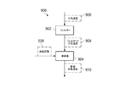
次に図9を参照する。図9は、一実施形態による警報速度を識別する論理の図である。この実施例では、論理900は、航空機の警報速度をノットで識別するように構成されている。論理900は、図2の閾値生成器224において実行される。
Reference is now made to FIG. FIG. 9 is a logic diagram that identifies the alert speed according to one embodiment. In this example,
図示のように、論理900は、フィルター902及び乗算器904を含む。フィルター902は、入力として対気速度906を受信するように構成されている。この実施例では、対気速度906は、航空機の真対気速度をノットで表したものである。フィルター902は、例えばローパスフィルターである。具体的には、フィルター902は、一次ローパスフィルターである。
As shown,
フィルター902は、対気速度906を使用してフィルタード対気速度908を生成する。フィルタード対気速度908は、図5の速度因数538とともに入力として乗算器904へ送られる。乗算器904は、速度因数538とフィルタード対気速度908を乗算して、警報対気速度910を生成する。ある場合には、警報対気速度910は、例えば図2の速度閾値234等の速度閾値として使用して、警報を発信する。
他の実施例では、航空機の機動飛行を行っている時に、フィルタード対気速度908を図8の操縦速度因数834で乗算して、操縦警報対気速度を生成する。この操縦警報対気速度はまた、警報を発信するための速度閾値としても使用される。
In another embodiment, when the aircraft is in flight, the filtered
ここで、図10を参照する。図10は、一実施形態による警報を発信する論理を示す図である。論理1000は、警報が発信される一方法の一例である。論理1000は、図2の警報発信器226において実行される。
Reference is now made to FIG. FIG. 10 is a diagram illustrating logic for issuing an alarm according to one embodiment.
図示のように、論理1000は加算器1002及び比較ユニット1004とを含む。加算器1002は、図5のフィルタード迎え角522と、図5の警報迎え角532を入力として受信する。この方法において、図2の警報発信器226は、警報迎え角532を図2の迎え角閾値231として受信する。
As shown,
加算器1002は、フィルタード迎え角522と、マイナスの警報迎え角532を合計して、総計1006を生成する。比較ユニット1004は、総計1006をゼロと比較するように構成されている。総計1006がゼロよりも大きい場合、警報1008が発信される。警報1008は、図2の警報230の一実装形態の一例である。警報230は、例えば非限定的に、図4のスティックシェイカー422等の航空機のスティックシェーカーに送られるコマンドである。
The
図5に示す論理500、図6に示す論理600、図7に示す論理700、図8に示す論理800、図9に示す論理900及び図10に示す論理1000は、例示的な実施形態を実施可能な方式を物理的又はアーキテクチャ的に限定するものではない。図示した構成要素に加えて又は代えて、他の構成要素を使用することができる。幾つかの構成要素は任意選択になることもある。
The
また、ブロックは、幾つかの論理構成要素を示すために提示されている。実施形態において実行される場合、一又は複数のこれらのブロックは結合、分割、又は異なるブロックに結合及び分割される。さらに、図5〜10の一又は複数の論理を互いに組み合わせることができる。 Blocks are also presented to show some logical components. When implemented in an embodiment, one or more of these blocks are combined, divided, or combined and divided into different blocks. Further, one or more of the logic of FIGS. 5-10 can be combined with each other.
ここで、図11を参照する。図11は、一実施形態による揚力係数を識別するための表を示す図である。この実施例では、表1100は、図2の任意の数の表251のうちの一つの表の実装形態の一例である。具体的には、表1100は、図5の表ルックアップユニット504、図5の表ルックアップユニット506、及び図8の表ルックアップユニット801によって使用される表の実装形態の一例である。
Reference is now made to FIG. FIG. 11 is a diagram illustrating a table for identifying lift coefficients according to one embodiment. In this example, table 1100 is an example of one table implementation of any number of tables 251 in FIG. Specifically, table 1100 is an example of a table implementation used by
これらの実施例では、列1102は迎え角(単位:度)に対応し、行1104はフラップのデテント位置に対応する。表ルックアップユニットは迎え角及びフラップのデテント位置の形態の入力を使用して、表1100の中から揚力係数1106のうちの特定の揚力係数を識別する。いくつかの実施例では、表ルックアップユニットのへの入力が列1102の値及び/又は行1104の値に含まれていない場合、表ルックアップユニットは補間を利用して正確な揚力係数を識別する。
In these examples,
表1100の図は、表が表ルックアップユニットに対して実装される方法に対し限定するものではない。この実施例では、4つの列及び行のみが図示されている。しかしながら、他の実施例では、他の任意の数の列及び行が表1100に含まれる。 The diagram of table 1100 is not limited to the manner in which the table is implemented for the table lookup unit. In this example, only four columns and rows are shown. However, in other embodiments, table 1100 includes any other number of columns and rows.
ここで、一実施形態による揚力係数対マッハ数のグラフを示す図12を参照する。この実施例では、グラフ1200は、垂直軸1202と水平軸1204を備える。垂直軸1202は、揚力係数値を表す。水平軸1204は、マッハ数値を表す。
Reference is now made to FIG. 12, which shows a graph of lift coefficient versus Mach number according to one embodiment. In this example,
線1206は、マッハ数に対する航空機の失速揚力係数に対応している。図示したように、航空機の失速揚力係数は、航空機のマッハ数が変化すると変化する。
線1208は、航空機が潜在的な失速状態に陥った時に、警報を発信するために使用される幾つかの現在利用可能な警報システムによって発信される警報揚力係数に対応している。図示したように、使用される警報揚力係数は、飛行中に固定されたままであり、マッハ数が変化しても変化しない。この種の警報揚力係数が使用された時に、警報は、約0.38を上回るマッハ数に対して、航空機が失速揚力係数に到達した後までは発信されない。つまり、警報は、航空機がすでに失速した後でないと発信されない。
線1210は、図2の失速管理システム216によって生成された警報揚力係数に対応している。具体的には、線1210は警報揚力係数244に対応している。図示したように、警報揚力係数244は、失速揚力係数が変化した時に変化する。具体的には、警報揚力係数は常に、失速揚力係数よりも約10%低く保たれるように構成される。
航空機のマッハ数が変化した時に変化するように構成された警報揚力係数を使用することで、航空機が失速する前にはいつも警報が発信される。この方法において、オペレータは、航空機の失速を防止する、又は航空機の失速の可能性を低減するために任意の数の機動飛行を行うための十分な時間を取ることができる。 By using an alert lift coefficient that is configured to change when the aircraft's Mach number changes, an alert is always issued before the aircraft stalls. In this manner, the operator can take sufficient time to perform any number of maneuvered flights to prevent aircraft stall or reduce the possibility of aircraft stall.
次に図13を参照する。図13は、一実施形態による航空機の飛行を管理するプロセスをフロー図で示したものである。図13に示すプロセスは、図2の失速管理システム216を使用する航空機202に実装される。
Reference is now made to FIG. FIG. 13 is a flow diagram of a process for managing aircraft flight according to one embodiment. The process shown in FIG. 13 is implemented on an
このプロセスは、航空機の事前に識別された警報速度を使用して、航空機の警報迎え角を識別することによって開始される(工程1300)。工程1300では、警報迎え角は、初期の警報迎え角と複数のバイアスを使用して識別される。これらのバイアスには、例えば非限定的に、迎え角バイアス、マッハ補償バイアス、現在の翼荷重バイアス、及び速度ブレーキ補償バイアスのうちの少なくとも一つが含まれる。ある実施例では、初期の警報迎え角は、フラップのデテント位置及び表を使用して識別される。
The process begins by identifying the aircraft alert angle of attack using the aircraft's pre-identified alert speed (step 1300). In
このプロセスでは次に、警報迎え角を使用して航空機の警報揚力係数を識別する(工程1302)。工程1302において、警報揚力係数は、フラップのデテント位置及び表を使用して識別される。
The process then identifies the warning lift coefficient of the aircraft using the warning angle of attack (step 1302). In
その後、このプロセスでは、航空機の警報揚力係数と、現在の揚力係数を使用して、航空機の警報速度を識別する(工程1304)。この警報速度は、例えば警報マッハである。つまり、警報速度はマッハ数として表される。さらに、警報速度は、次の警報迎え角を識別するためのフィードバックとして使用される。 The process then identifies the alert speed of the aircraft using the aircraft alert lift coefficient and the current lift coefficient (step 1304). This alarm speed is, for example, an alarm Mach. That is, the alarm speed is expressed as a Mach number. In addition, the alert speed is used as feedback to identify the next alert angle of attack.
このプロセスでは次に、警報迎え角、警報揚力係数、及び警報速度のうちの少なくとも一つを使用して、航空機の潜在的な失速状態を示す警報を発信するのに使用される一組の閾値が識別される(工程1306)。この一組の閾値には、例えば、迎え角閾値、揚力係数閾値、及び/又は速度閾値が含まれる。ある場合には、迎え角閾値、揚力係数閾値、及び速度閾値はそれぞれ、警報迎え角、警報揚力係数、及び警報速度である。 The process then uses a warning angle of attack, a warning lift coefficient, and a warning speed to set a set of thresholds used to issue a warning that indicates a potential stall condition of the aircraft. Are identified (step 1306). This set of thresholds includes, for example, an attack angle threshold, a lift coefficient threshold, and / or a speed threshold. In some cases, the angle of attack threshold, the lift coefficient threshold, and the speed threshold are an alert angle of attack, an alert lift coefficient, and an alert speed, respectively.
次に、このプロセスでは、一組の閾値のうちの少なくとも一つの閾値が交差した時に警報が発信され(工程1308)、その後プロセスは終了する。工程1308では、警報は、例えば航空機の迎え角が迎え角閾値よりも大きい、航空機の現在の揚力係数が警報揚力係数よりも大きい、また航空機の速度が速度閾値を下回ることのうちの少なくとも一つが起きた時に、発信される。
The process then issues an alarm when at least one threshold of the set of thresholds crosses (step 1308), after which the process ends. In
図13では、警報迎え角を識別するフィードバックとして警報速度を使用することによって、警報迎え角を使用して識別された警報揚力係数を、航空機の現在の状態の任意の数の変化に応じて調節することができる。つまり、警報迎え角、警報揚力係数、及び警報速度は、航空機の現在の状態の変化にしたがって調節可能である。この方法においては、航空機が潜在的な失速状態に陥ったという警報が、航空機が実際に失速する前に発信される。 In FIG. 13, by using the alert speed as feedback identifying the alert angle of attack, the alert lift coefficient identified using the alert angle of attack is adjusted in response to any number of changes in the current state of the aircraft. can do. That is, the warning angle of attack, warning lift coefficient, and warning speed can be adjusted according to changes in the current state of the aircraft. In this method, an alert that the aircraft has entered a potential stall condition is sent out before the aircraft actually stalls.
図示した種々の実施形態でのフロー図、論理及びブロック図は、例示的な実施形態で実装可能な装置及び方法の構造、機能、及び工程を示している。その際、フロー図、論理又はブロック図の各ブロックは、工程又はステップのモジュール、セグメント、機能及び/又は部分を表わしている。例えば、ブロックの一又は複数は、ハードウェア内のプログラムコードとして、又はプログラムコードとハードウェアの組合せとして実施可能である。ハードウェアにおいて実施されるとき、ハードウェアは、例えば、フロー図又はブロック図の一又は複数の工程を実施するように製造又は構成された集積回路の形態をとることができる。 The flow diagrams, logic, and block diagrams in the various illustrated embodiments illustrate the structure, functionality, and process of devices and methods that can be implemented in exemplary embodiments. Here, each block of the flow diagram, logic, or block diagram represents a module, segment, function, and / or portion of a process or step. For example, one or more of the blocks can be implemented as program code in hardware or as a combination of program code and hardware. When implemented in hardware, the hardware can take the form of, for example, an integrated circuit that is manufactured or configured to perform one or more steps in a flowchart or block diagram.
例示的な一実施形態の幾つかの代替的な実装態様では、ブロックに記載された1つ又は複数の機能は、図中に記載の順序を逸脱して現れることがある。例えば、場合によっては、連続して示されている二つのブロックがほぼ同時に実行されること、又は時には含まれる機能によってはブロックが逆順に実施されることもありうる。また、フロー図、論理又はブロック図に示されているブロックに加えて他のブロックが追加されてもよい。 In some alternative implementations of an exemplary embodiment, one or more functions described in a block may appear out of the order described in the figures. For example, in some cases, two blocks shown in succession may be executed at approximately the same time, or sometimes the blocks may be executed in reverse order depending on the functions involved. In addition to the blocks shown in the flow diagram, logic, or block diagram, other blocks may be added.
次に図14を注目する。図14は、一実施形態によるデータ処理システムを示す図である。この例示的な実施例では、データ処理システム1400を使用して、図2のコンピュータシステム222に一又は複数のコンピュータを実装することができる。この実施例では、データ処理システム1400は通信フレームワーク1402を含み、これによりプロセッサユニット1404、メモリ1406、固定記憶域1408、通信ユニット1410、入出力(I/O)ユニット1412、及びディスプレイ1414の間の通信が行われる。
Attention is now directed to FIG. FIG. 14 is a diagram illustrating a data processing system according to an embodiment. In this illustrative example,
プロセッサユニット1404は、メモリ1406に読み込まれうるソフトウェアに対する命令を実行するように働く。プロセッサユニット1404は、特定の実行形態に応じて、任意の数のプロセッサ、マルチプロセッサコア、又は他の形式のプロセッサであってもよい。さらに、プロセッサ装置1404は、単一チップ上でメインプロセッサが二次プロセッサと共存する異種プロセッサシステムを任意の個数だけ使用して実装することもできる。別の例示された実施例では、プロセッサユニット1404は同一形式の複数のプロセッサを含む対称型マルチプロセッサシステムであってもよい。
The
メモリ1406及び固定記憶域1408は、記憶デバイス1416の例である。記憶デバイスは、例えば、限定しないが、データ、機能的な形態のプログラムコード、及び/又は他の適切な情報などの情報を、一時的に及び/又は永続的に保存することができる任意の個数のハードウェアである。記憶デバイス1416は、これらの実施例ではコンピュータで読取可能な記憶デバイスと呼ばれることもある。これらの実施例では、メモリ1406は例えば、ランダムアクセスメモリ又は他の何らかの適切な揮発性又は不揮発性の記憶デバイスであってもよい。固定記憶域1408は具体的な実装に応じて様々な形態をとりうる。
例えば、限定しないが、固定記憶域1408は一又は複数の構成要素又はデバイスを含みうる。例えば、固定記憶域1408は、ハードドライブ、フラッシュメモリ、書換え型光ディスク、書換え可能磁気テープ、又はそれらの何らかの組み合わせである。固定記憶域1408によって使用される媒体は着脱式であってもよい。例えば、着脱式ハードドライブは固定記憶域1408に使用することができる。
For example, without limitation,
通信ユニット1410はこれらの例では、他のデータ処理システム又はデバイスとの通信を行う。このような実施例では、通信ユニット1410はネットワークインターフェースカードである。通信ユニット1410は、物理的及び無線の通信リンクのいずれか一方又は両方を使用することによって、通信を提供することができる。
In these examples,
入出力ユニット1412は、データ処理システム1400に接続される他の装置とのデータの入出力を可能にする。例えば、入出力ユニット1412は、キーボード、マウス、及び/又は他のなんらかの適切な入力デバイスを介してユーザ入力への接続を提供することができる。さらに、入出力ユニット1412は出力をプリンタに送ることができる。ディスプレイ1414はユーザに情報を表示するメカニズムを提供する。
The input /
オペレーティングシステム、アプリケーション、及び/又はプログラムに対する命令は、通信フレームワーク1402を介してプロセッサユニット1404と通信する記憶デバイス1416内に位置付けされる。このような実施例では、命令は固定記憶域1408上において機能的な形態になっている。これらの命令は、プロセッサユニット1404によって実行するため、メモリ1406に読み込まれうる。異なる実施形態のプロセスは、メモリ1406などのメモリに配置可能なコンピュータによって実行される命令を使用して、プロセッサユニット1404によって実行することができる。
Instructions for the operating system, applications, and / or programs are located in the
これらの命令は、プログラムコード、コンピュータで使用可能なプログラムコード、又はコンピュータで読取可能なプログラムコードと呼ばれ、プロセッサユニット1404内のプロセッサによって読取及び実行することができる。異なる実施形態のプログラムコードは、メモリ1406又は固定記憶域1408など、異なる物理的な又はコンピュータ可読記憶媒体上に具現化しうる。
These instructions are referred to as program code, computer usable program code, or computer readable program code that may be read and executed by a processor in
プログラムコード1418は、選択的に着脱可能でコンピュータで読取可能な媒体1420上に機能的な形態で配置され、プロセッサユニット1404での実行用のデータ処理システム1400に読込み又は転送することができる。プログラムコード1418及びコンピュータ可読媒体1420は、これらの実施例ではコンピュータプログラム製品1422を形成する。1つの実施例では、コンピュータで読取可能な媒体1420は、コンピュータで読取可能な記憶媒体1424又はコンピュータで読取可能な信号媒体1426であってもよい。
コンピュータ可読記憶媒体1424は、例えば非限定的に、固定記憶域1408の一部であるハードドライブなどのように、記憶デバイス上に転送するための固定記憶域1408の一部であるドライブ又は他のデバイスに挿入又は配置される光ディスク又は磁気ディスクなどを含みうる。また、コンピュータ可読記憶媒体1424は、データ処理システム1400に接続されているハードドライブ、サムドライブ、又はフラッシュメモリなどの固定記憶域の形態をとることができる。場合によっては、コンピュータ可読記憶媒体1424は、データ処理システム1400から着脱式でなくてもよい。
The computer-
これらの実施例では、コンピュータで読取可能な記憶媒体1424は、プログラムコード1418を伝搬又は転送する媒体よりはむしろプログラムコード1418を保存するために使用される物理的な又は有形の記憶デバイスである。コンピュータで読取可能な記憶媒体1424は、コンピュータで読取可能な有形の記憶デバイス又はコンピュータで読取可能な物理的な記憶デバイスと呼ばれることもある。すなわち、コンピュータで読取可能な記憶媒体1424は、人が触れることのできる媒体である。
In these illustrative examples, computer-
代替的には、プログラムコード1418は、コンピュータ可読信号媒体1426を使用してデータ処理システム1400に転送することができる。コンピュータで読取可能な信号媒体1426は、例えば非限定的に、プログラムコード1418を含む伝播されたデータ信号であってもよい。例えば、コンピュータで読取可能な信号媒体1426は、電磁信号、光信号、及び/又は他の任意の好適な形式の信号である。これらの信号は、無線通信リンク、光ファイバケーブル、同軸ケーブル、有線、及び/又は他の任意の好適な形式の通信リンクなどの通信リンクによって伝送される。すなわち、通信リンク及び/又は接続は、実施例によると物理的なもの又は無線によるものでありうる。
Alternatively,
幾つかの例示的な実施形態では、プログラムコード1418は、コンピュータで読取可能な信号媒体1426により、ネットワークを介して別のデバイス又はデータ処理システムから固定記憶域1408にダウンロードされて、データ処理システム1400内で使用される。例えば、サーバーデータ処理システムのコンピュータ可読記憶媒体に保存されたプログラムコードは、ネットワークを介してサーバーからデータ処理システム1400にダウンロードすることができる。プログラムコード1418を提供するデータ処理システムは、サーバコンピュータ、クライアントコンピュータ、又はプログラムコード1418を記憶及び転送可能な別の装置とすることができる。
In some exemplary embodiments,
データ処理システム1400に例示されている種々の構成要素は、種々の実施形態が実行可能である方法をアーキテクチャ的に制限するものではない。異なる例示的実施形態は、データ処理システム1400に対して図解されている構成要素に対して追加的又は代替的な構成要素を含むデータ処理システム内に実装しうる。図14に示した他の構成要素は、例示的な実施例と異なることがある。種々の実施形態は、プログラムコードを実行できる任意のハードウェア装置又はシステムを用いて実施することができる。一実施例として、データ処理システムは、無機構成要素と一体化した有機構成要素を含むことができる、及び/又は全体的に人間を除く有機構成要素が含まれえる。例えば、記憶デバイスは、有機半導体で構成されている。
The various components illustrated in
別の例示的な実施例では、プロセッサユニット1404は、特定の用途のために製造又は構成された回路を有するハードウェアユニットの形態をとってもよい。この種のハードウェアは、工程を実行するように構成された記憶デバイスからメモリにプログラムコードをローディングする必要なく、工程を実施することができる。
In another illustrative example,
例えば、プロセッサユニット1404がハードウェアユニットの形態をとる場合、プロセッサユニット1404は回路システム、特定用途向け集積回路(ASIC)、プログラム可能論理デバイス、又は任意の数の工程を実施するために構成された他の適切な形式のハードウェアであってもよい。プログラム可能論理デバイスにより、デバイスは任意の数の工程を実施するように構成されている。デバイスは、後で再構成することができるか、又は任意の数の工程を実行するように恒久的に構成することができる。プログラマブル論理デバイスの例には、例えば非限定的に、プログラマブル論理アレイ、フィールドプログラマブル論理アレイ、フィールドプログラマブルゲートアレイ、及び他の適切なハードウェアデバイスが含まれる。この形式の実装により、異なる実施形態のプロセスはハードウェアユニットに実装されるため、プログラムコード1418は除外されうる。
For example, if the
さらに別の例示的な実施例では、プロセッサユニット1404は、コンピュータ及びハードウェアユニットの中に見られるプロセッサの組み合わせを使用して実装可能である。プロセッサユニット1404は、プログラムコード1418を実行するように構成されている任意の数のハードウェアユニット及び任意の数のプロセッサを有していてもよい。ここに描かれている実施例では、プロセスの一部は任意の数のハードウェアユニットで実行することが可能であるが、一方、他のプロセスは任意の数のプロセッサで実行可能である。
In yet another exemplary embodiment,
別の実施例では、バスシステムは、通信フレームワーク1402を実施するために使用することができ、システムバス又は入出力バスといった一又は複数のバスから構成することができる。言うまでもなく、バスシステムは、バスシステムに取り付けられた種々の構成要素又はデバイスの間でのデータ伝送を行う任意の適切な種類のアーキテクチャを使用して実施することができる。
In another embodiment, the bus system can be used to implement the
加えて、通信ユニットは、データの送信、データの受信、又はデータの送受信を行う任意の数のデバイスを含むことがある。通信ユニットは、例えば、モデム又はネットワークアダプタ、2つのネットワークアダプタ、又はこれらの組み合わせとしてもよい。さらに、メモリは、例えば非限定的に、通信フレームワーク1402内に存在することがあるインターフェース及びメモリコントローラハブに見られるような、メモリ1406又はキャッシュであってもよい。
In addition, a communication unit may include any number of devices that transmit data, receive data, or transmit and receive data. The communication unit may be, for example, a modem or network adapter, two network adapters, or a combination thereof. Further, the memory may be a
このように、一又は複数の実施形態により、航空機を操縦可能な速度のより正確な識別が実施できる。異なる実施形態は、飛行の異なる段階における航空機の揚力の変化を考慮に入れている。具体的には、この実施形態は、航空機の様々な状態が変化する時に航空機の揚力が変化することを認識し、考慮している。これらの異なる状態を考慮することによって、現在使用されているシステムに比べて、航空機がより短い滑走路を有する空港において操作可能になる。 As such, one or more embodiments can provide more accurate identification of the speed at which an aircraft can be maneuvered. Different embodiments take into account changes in aircraft lift at different stages of flight. Specifically, this embodiment recognizes and takes into account that the lift of an aircraft changes as the various states of the aircraft change. Considering these different conditions allows the aircraft to operate at airports with shorter runways compared to currently used systems.
種々の実施形態の説明は、例示及び説明を目的として提供されているものであり、網羅的な説明であること、又は開示された形態に実施形態を限定することを意図していない。当業者には、多数の修正例及び変形例が明らかであろう。さらに、種々の実施形態は、他の実施形態に照らして別の利点を提供することができる。選択された一又は複数の実施形態は、実施形態の原理、実際の用途を最もよく説明するため、及び他の当業者に対し、様々な実施形態の開示内容と、考慮される特定の用途に適した様々な修正との理解を促すために選択及び記述されている。 The description of the various embodiments is provided for purposes of illustration and description, and is not intended to be exhaustive or limited to the embodiments disclosed. Many modifications and variations will be apparent to practitioners skilled in this art. Further, the various embodiments can provide other advantages in view of other embodiments. The selected embodiment (s) are intended to best explain the principles of the embodiments, practical applications, and to others skilled in the art in terms of the disclosure of the various embodiments and the specific applications considered. Selected and described to facilitate understanding of various suitable modifications.
100 航空機
102 翼
104 翼
106 機体
108 エンジン
110 エンジン
112 尾部
114 水平安定板
116 水平安定板
118 垂直安定板
200 航空機環境
202 航空機
204 揚力
205 大気
206 任意の数の因数
208 任意の数の航空機因数
210 任意の数の動的因数
212 任意の数の環境因数
214 センサシステム
216 失速管理システム
217 オペレータ
218 任意の数のセンサ
220 データ
222 コンピュータシステム
224 閾値生成器
226 警報発信器
228 一組の閾値
230 警報
231 迎え角閾値
232 揚力係数
234 速度閾値
236 迎え角
238 翼の形状
240 揚力係数
242 警報迎え角
244 警報揚力係数
246 警報速度
248 フィードバック
250 任意の数のデータ構造
251 任意の数の表
252 モデル
256 潜在的な失速状態
302 重量
304 迎え角
306 翼の形状
308 バンク角
310 標準の荷重倍数
312 任意の数の外部荷重ストア
314 操縦面の位置
315 フラップの位置
316 スラットの位置
318 速度
320 マッハ数
322 真対気速度
324 較正対気速度
326 気温
328 静圧
330 ラム気圧
400 飛行制御システム
402 任意の数のシステムコントローラ
403 任意の数の飛行制御デバイス
404 オートパイロット
406 エンジンコントローラ
408 操縦面コントローラ
410 任意の数のエンジン
412 任意の数の操縦面
413 操縦桿
414 触覚警報
416 視覚警報
418 聴覚警報
420 メッセージ
422 スティックシェイカー
424 飛行計器システム
426 ディスプレイシステム
428 オーディオシステム
430 昇降舵
432 スラット
500 警報速度を識別するのに使用される論理
502 フィルター
504 表のルックアップユニット
506 表のルックアップユニット
508 加算器
510 除算器
512 平方根ユニット
514 乗算器
516 フィルター
520 修正迎え角
522 フィルタード迎え角
524 フラップのデテント位置
526 初期の揚力係数
528 デルタ揚力係数
530 揚力係数
532 警報迎え角
534 警報揚力係数
536 揚力因数
538 速度因数
540 フィルタードマッハ
542 マッハ
544 警報マッハ
600 警報迎え角を識別する論理
602 表のルックアップユニット
604 加算器
610 初期の警報迎え角
612 マッハ補償バイアス
614 現在の翼荷重バイアス
616 速度ブレーキ補償バイアス
618 任意の数の他の迎え角バイアス
620 迎え角バイアス
700 マッハ補償バイアスを識別するために使用される論理
702 表のルックアップユニット
704 表のルックアップユニット
706 表のルックアップユニット
708 加算器
710 乗算器
712 選択上限ユニット
714 決定ユニット
716 フラップアップマッハバイアス
718 インターセプトバイアス
720 スロープバイアス
722 積
724 総計
727 上限値
728 フラップアップの指示
800 旋回操縦中の最低操縦速度を識別する論理
801 表ルックアップユニット
802 除算器
804 除算器
806 乗算器
808 平方根ユニット
810 乗算器
812 加算器
814 加算器
816 乗算器
818 選択上限ユニット
820 操縦警報迎え角
822 操縦警報揚力係数
824 選択荷重(〜1.3G)
826 荷重倍数
828 操縦要因
830 調節揚力係数
832 操縦揚力係数
834 操縦速度係数
836 最低操縦警報マッハ
838 操縦マッハ補償バイアス
840 積
900 警報速度を識別する論理
902 フィルター
904 乗算器
906 対気速度
908 フィルタード対気速度
910 警報対気速度
1000 警報を発信する論理
1002 加算器
1004 比較ユニット
1006 総計
1008 警報
1100 揚力係数を識別するための表
1102 迎え角(度)
1104 フラップのデテント位置(度)
1106 揚力係数
1200 揚力係数対マッハ数のグラフ
1202 揚力係数(CL)
1204 マッハ数
1206 グラフの線
1208 グラフの線
1400 データ処理システム
1404 プロセッサユニット
1406 メモリ
1408 固定記憶域
1410 通信ユニット
1412 入力/出力ユニット
1414 表示装置
1416 記憶デバイス
1418 プログラムコード
1420 コンピュータによって読み取り可能な媒体
1422 コンピュータプログラム製品
1424 コンピュータによって読み取り可能な記憶媒体
1426 コンピュータによって読み取り可能な信号媒体
100 Aircraft 102 Wings 104 Wings 106 Airframe 108 Engine 110 Engine 112 Tail 114 Horizontal Stabilizer 116 Horizontal Stabilizer 118 Vertical Stabilizer 200 Aircraft Environment 202 Aircraft 204 Lift 205 Atmosphere 206 Arbitrary Number Factor 208 Arbitrary Number Aircraft Factor 210 Arbitrary Number of dynamic factors 212 Arbitrary number of environmental factors 214 Sensor system 216 Stall management system 217 Operator 218 Arbitrary number of sensors 220 Data 222 Computer system 224 Threshold generator 226 Alarm transmitter 228 Set of thresholds 230 Alarm 231 Angular threshold 232 Lift coefficient 234 Speed threshold 236 Angle of attack 238 Wing shape 240 Lift coefficient 242 Warning angle of attack 244 Alarm lift coefficient 246 Alarm speed 248 Feedback 250 Any number of data Structure 251 Arbitrary number of tables 252 Model 256 Potential stall condition 302 Weight 304 Angle of attack 306 Wing shape 308 Bank angle 310 Standard load multiple 312 Arbitrary number of external load stores 314 Control surface position 315 Flap position 316 Slat position 318 Speed 320 Mach number 322 True air speed 324 Calibration air speed 326 Air temperature 328 Static pressure 330 Ram air pressure 400 Flight control system 402 Any number of system controllers 403 Any number of flight control devices 404 Autopilot 406 Engine Controller 408 Control surface controller 410 Any number of engines 412 Any number of control surfaces 413 Control stick 414 Tactile alarm 416 Visual alarm 418 Hearing alarm 420 Message 422 Stick shaker 424 Flight Table system 426 display system 428 audio system 430 elevator 432 slat 500 logic used to identify alarm speed 502 filter 504 table lookup unit 506 table lookup unit 508 adder 510 divider 512 square root unit 514 multiplication Device 516 Filter 520 Modified angle of attack 522 Filtered angle of attack 524 Detent position of flap 526 Initial lift coefficient 528 Delta lift coefficient 530 Lift coefficient 532 Warning angle of attack 534 Warning lift coefficient 536 Lift factor 538 Speed factor 540 Filtered Mach 542 Mach Alarm Mach 600 Logic identifying alarm angle of attack 602 Table lookup unit 604 Adder 610 Initial alarm angle of attack 612 Mach compensation bar Ias 614 Current wing load bias 616 Speed brake compensation bias 618 Any number of other angle of attack bias 620 Angle of attack bias 700 Logic used to identify Mach compensation bias 702 Table lookup unit 704 Table lookup Unit 706 Table Lookup Unit 708 Adder 710 Multiplier 712 Selection Upper Limit Unit 714 Determination Unit 716 Flap Up Mach Bias 718 Intercept Bias 720 Slope Bias 722 Product 724 Total 727 Upper Limit 728 Flaps Up Instruction 800 Minimum Maneuver During Turn Maneuver Logic to identify speed 801 Table lookup unit 802 Divider 804 Divider 806 Multiplier 808 Square root unit 810 Multiplier 812 Adder 814 Adder 16 multiplier 818 selected upper unit 820 maneuver alert angle of attack 822 maneuver alert lift coefficient 824 selected load (~1.3G)
826 Load multiple 828
1104 Flap detent position (degrees)
1106
1204
Claims (8)
前記航空機(202)の事前に識別された警報速度(248)を使用して、前記航空機(202)の警報迎え角(242)を識別することと、
前記航空機(202)の前記警報迎え角(242)を使用して、前記航空機(202)の警報揚力係数(244)を識別することと、
前記航空機(202)の前記警報揚力係数(244)と、前記航空機(202)の現在の揚力係数(240)を使用して、前記航空機(202)の警報速度(246)を識別することと、
前記警報迎え角(242)、前記警報揚力係数(244)、及び前記警報速度(246)のうちの少なくとも一つを使用して、前記航空機(202)の潜在的な失速状態(256)を示す警報(230)を発信するのに使用される一組の閾値(228)を識別することと
を含む方法。 A method for managing an aircraft (202) in flight, comprising:
Identifying a warning angle of attack (242) of the aircraft (202) using a pre-identified warning speed (248) of the aircraft (202);
Identifying the warning lift coefficient (244) of the aircraft (202) using the warning angle of attack (242) of the aircraft (202);
Identifying the alert speed (246) of the aircraft (202) using the alert lift coefficient (244) of the aircraft (202) and the current lift coefficient (240) of the aircraft (202) ;
At least one of the alert angle of attack (242), the alert lift coefficient (244), and the alert speed (246) is used to indicate a potential stall condition (256) of the aircraft (202). Identifying a set of thresholds (228) used to raise an alarm (230) .
前記警報迎え角(242)を使用して迎え角閾値(231)、前記警報揚力係数(244)を使用して揚力係数閾値(232)、及び前記警報速度(246)を使用して速度閾値(234)のうちの少なくとも一つを識別することを含む、請求項1に記載の方法。 Identifying a set of thresholds (228) used to emit an alarm (230) indicating a potential stall condition (256) of the aircraft (202);
Using the warning angle of attack (242), the threshold angle of attack (231), using the warning lift coefficient (24 4 ), the lift coefficient threshold (232), and using the warning speed (246), the speed threshold at least one comprises identifying a method according to claim 1 of (234).
前記航空機(202)のスティックシェイカー(422)へ前記警報(230)を送ること
をさらに含む、請求項2に記載の方法。 When at least one of the angle of attack (236) of the aircraft (202) is greater than the angle of attack threshold (231), the current lift coefficient (240) of the aircraft (202) is the lift coefficient threshold (232). ) And when the aircraft speed falls below the speed threshold (234), the alarm (230) is emitted;
The method of claim 2 , further comprising sending the alert (230) to a stick shaker (422) of the aircraft (202).
前記航空機(202)の事前に識別された警報速度(248)を使用して、前記航空機(202)の警報迎え角(242)を識別することと、
前記航空機(202)の前記警報迎え角(242)を使用して、前記航空機(202)の警報揚力係数(244)を識別することと、
前記航空機(202)の前記警報揚力係数(244)と、前記航空機(202)の現在の揚力係数(240)を使用して、前記航空機(202)の警報速度(246)を識別することと
を含み、
前記航空機(202)の事前に識別された警報速度(248)を使用して、前記航空機(202)の警報迎え角(242)を識別するステップが、
フラップのデテント位置(524)と表(602)を使用して、初期の警報迎え角(610)を識別することと、
前記航空機(202)の前記事前に識別された警報速度(248)を使用してマッハ補償バイアス(612)を識別することと、
前記初期の警報迎え角(610)と前記マッハ補償バイアス(612)とを使用して、前記航空機(202)の前記警報迎え角(242)を識別することと
を含む、方法。 A method for managing an aircraft (202) in flight, comprising:
Identifying a warning angle of attack (242) of the aircraft (202) using a pre-identified warning speed (248) of the aircraft (202);
Identifying the warning lift coefficient (244) of the aircraft (202) using the warning angle of attack (242) of the aircraft (202);
Identifying the alert speed (246) of the aircraft (202) using the alert lift coefficient (244) of the aircraft (202) and the current lift coefficient (240) of the aircraft (202); seen including,
Identifying the alert angle of attack (242) of the aircraft (202) using the pre-identified alert speed (248) of the aircraft (202);
Using the flap detent position (524) and the table (602) to identify the initial warning angle of attack (610);
Identifying a Mach compensation bias (612) using the pre-identified alert speed (248) of the aircraft (202);
Identifying the warning angle of attack (242) of the aircraft (202) using the initial warning angle of attack (610) and the Mach compensation bias (612);
Including a method.
前記初期の警報迎え角(610)と、前記マッハ補償バイアス(612)と、現在の翼荷重バイアス(614)、速度ブレーキ補償バイアス(616)、及び迎え角バイアス(618)のうちの少なくとも一つとを使用して、前記航空機(202)の前記警報迎え角(242)を識別すること
を含む、請求項4に記載の方法。 Identifying the warning angle of attack (242) of the aircraft (202) using the initial warning angle of attack (610) and the Mach compensation bias (612);
At least one of the initial warning angle of attack (610), the Mach compensation bias (612), a current blade load bias (614), a speed brake compensation bias (616), and an angle of attack bias (618); The method of claim 4 , comprising identifying the alert angle of attack (242) of the aircraft (202) using.
前記航空機(202)の事前に識別された警報速度(248)を使用して、前記航空機(202)の警報迎え角(242)を識別することと、
前記航空機(202)の前記警報迎え角(242)を使用して、前記航空機(202)の警報揚力係数(244)を識別することと、
前記航空機(202)の前記警報揚力係数(244)と、前記航空機(202)の現在の揚力係数(240)を使用して、前記航空機(202)の警報速度(246)を識別することと
を含み、
前記航空機(202)の前記警報迎え角(242)を使用して、前記航空機(202)の前記警報揚力係数(244)を識別するステップが、
前記航空機(202)の前記警報迎え角(242)、フラップのデテント位置(524)、及び表(506)を使用して、前記航空機(202)の前記警報揚力係数(244)を識別することと
を含む、方法。 A method for managing an aircraft (202) in flight, comprising:
Identifying a warning angle of attack (242) of the aircraft (202) using a pre-identified warning speed (248) of the aircraft (202);
Identifying the warning lift coefficient (244) of the aircraft (202) using the warning angle of attack (242) of the aircraft (202);
Identifying the alert speed (246) of the aircraft (202) using the alert lift coefficient (244) of the aircraft (202) and the current lift coefficient (240) of the aircraft (202); seen including,
Identifying the alert lift coefficient (244) of the aircraft (202) using the alert angle of attack (242) of the aircraft (202);
Identifying the warning lift coefficient (244) of the aircraft (202) using the warning angle of attack (242), flap detent position (524), and table (506) of the aircraft (202);
Including a method.
前記航空機(202)の事前に識別された警報速度(248)を使用して、前記航空機(202)の警報迎え角(242)を識別することと、
前記航空機(202)の前記警報迎え角(242)を使用して、前記航空機(202)の警報揚力係数(244)を識別することと、
前記航空機(202)の前記警報揚力係数(244)と、前記航空機(202)の現在の揚力係数(240)を使用して、前記航空機(202)の警報速度(246)を識別することと
を含み、
前記航空機(202)の前記警報揚力係数(244)と、前記航空機(202)の前記現在の揚力係数(240)を使用して前記航空機(202)の前記警報速度(246)を識別するステップが、
修正迎え角(520)、フラップのデテント位置(524)、及び表(504)を使用して、前記航空機(202)の前記現在の揚力係数(240)を識別することと、
前記現在の揚力係数(240)を前記警報揚力係数(244)で除算することによって、揚力因数(536)を生成することと、
前記揚力因数(536)の平方根(512)を識別して、速度因数(538)を生成することと、
前記速度因数(538)と前記航空機(202)の現在の速度を使用して、前記警報速度(246)を識別することとを含み、
前記警報速度(246)が、前記航空機(202)の警報マッハ(544)であり、前記現在の速度が前記航空機(202)の現在のマッハである、方法。 A method for managing an aircraft (202) in flight, comprising:
Identifying a warning angle of attack (242) of the aircraft (202) using a pre-identified warning speed (248) of the aircraft (202);
Identifying the warning lift coefficient (244) of the aircraft (202) using the warning angle of attack (242) of the aircraft (202);
Identifying the alert speed (246) of the aircraft (202) using the alert lift coefficient (244) of the aircraft (202) and the current lift coefficient (240) of the aircraft (202); seen including,
Identifying the alert speed (246) of the aircraft (202) using the alert lift coefficient (244) of the aircraft (202) and the current lift coefficient (240) of the aircraft (202); ,
Identifying the current lift coefficient (240) of the aircraft (202) using a modified angle of attack (520), a flap detent position (524), and a table (504);
Generating a lift factor (536) by dividing the current lift coefficient (240) by the warning lift coefficient (244);
Identifying the square root (512) of the lift factor (536) to generate a velocity factor (538);
Identifying the alert speed (246) using the speed factor (538) and the current speed of the aircraft (202);
The method wherein the alert speed (246) is an alert Mach (544) of the aircraft (202) and the current speed is a current Mach of the aircraft (202) .
前記航空機(202)の事前に識別された警報速度(248)を使用して、前記航空機(202)の警報迎え角(242)を識別することと、
前記航空機(202)の前記警報迎え角(242)を使用して、前記航空機(202)の警報揚力係数(244)を識別することと、
前記航空機(202)の前記警報揚力係数(244)と、前記航空機(202)の現在の揚力係数(240)を使用して、前記航空機(202)の警報速度(246)を識別することと
を含み、
前記航空機(202)の前記警報迎え角(242)を使用して、前記航空機(202)の前記警報揚力係数(244)を識別するステップが、
前記航空機(202)の前記警報迎え角(242)を使用して、前記航空機(202)の前記警報揚力係数(244)を識別することを含み、前記警報揚力係数(244)が、前記航空機の現在の失速揚力係数よりも実質的に選択割合だけ小さい、方法。 A method for managing an aircraft (202) in flight, comprising:
Identifying a warning angle of attack (242) of the aircraft (202) using a pre-identified warning speed (248) of the aircraft (202);
Identifying the warning lift coefficient (244) of the aircraft (202) using the warning angle of attack (242) of the aircraft (202);
Identifying the alert speed (246) of the aircraft (202) using the alert lift coefficient (244) of the aircraft (202) and the current lift coefficient (240) of the aircraft (202); seen including,
Identifying the alert lift coefficient (244) of the aircraft (202) using the alert angle of attack (242) of the aircraft (202);
Identifying the warning lift coefficient (244) of the aircraft (202) using the warning angle of attack (242) of the aircraft (202), wherein the warning lift coefficient (244) A method that is substantially a select percentage smaller than the current stall lift coefficient .
Applications Claiming Priority (2)
| Application Number | Priority Date | Filing Date | Title |
|---|---|---|---|
| US13/526,198 US8653990B2 (en) | 2012-06-18 | 2012-06-18 | Stall management system |
| US13/526,198 | 2012-06-18 |
Publications (2)
| Publication Number | Publication Date |
|---|---|
| JP2014000951A JP2014000951A (en) | 2014-01-09 |
| JP6235801B2 true JP6235801B2 (en) | 2017-11-22 |
Family
ID=48699544
Family Applications (1)
| Application Number | Title | Priority Date | Filing Date |
|---|---|---|---|
| JP2013121203A Active JP6235801B2 (en) | 2012-06-18 | 2013-06-07 | Stall management system |
Country Status (7)
| Country | Link |
|---|---|
| US (1) | US8653990B2 (en) |
| EP (1) | EP2676883B1 (en) |
| JP (1) | JP6235801B2 (en) |
| CN (1) | CN103514360B (en) |
| CA (1) | CA2809951C (en) |
| ES (1) | ES2698249T3 (en) |
| RU (1) | RU2601061C2 (en) |
Families Citing this family (18)
| Publication number | Priority date | Publication date | Assignee | Title |
|---|---|---|---|---|
| JP6114075B2 (en) * | 2013-03-07 | 2017-04-12 | 三菱航空機株式会社 | Aircraft warning system and aircraft |
| US9366546B2 (en) | 2014-02-24 | 2016-06-14 | Lockheed Martin Corporation | Projected synthetic vision |
| US9522742B2 (en) * | 2014-03-18 | 2016-12-20 | The Boeing Company | Short landing warning |
| US9563276B2 (en) | 2014-03-26 | 2017-02-07 | Lockheed Martin Corporation | Tactile and peripheral vision combined modality hover drift cueing |
| US10227140B2 (en) * | 2014-07-11 | 2019-03-12 | Cmc Electronics Inc | System and method for detecting and alerting the user of an aircraft of an impendent adverse condition |
| US9821903B2 (en) | 2014-07-14 | 2017-11-21 | The Boeing Company | Closed loop control of aircraft control surfaces |
| WO2016191320A1 (en) * | 2015-05-22 | 2016-12-01 | Tiger Century Aircraft, Inc. | Aircraft energy state awareness display systems and methods |
| US9845146B2 (en) * | 2015-10-23 | 2017-12-19 | The Boeing Company | Zoom climb prevention system for enhanced performance |
| CN106347636B (en) * | 2016-08-30 | 2019-03-01 | 中国航空工业集团公司西安飞行自动控制研究所 | A kind of push rod stall protection control method |
| FR3057370B1 (en) * | 2016-10-11 | 2019-08-23 | Airbus Operations | METHOD AND SYSTEM FOR CONTROLLING FLIGHT OF AN AIRCRAFT |
| US10228692B2 (en) | 2017-03-27 | 2019-03-12 | Gulfstream Aerospace Corporation | Aircraft flight envelope protection and recovery autopilot |
| CN107651171A (en) * | 2017-09-30 | 2018-02-02 | 江西洪都航空工业集团有限责任公司 | Aircraft tailspin state auxiliary driving device |
| CN107622180B (en) * | 2017-09-30 | 2021-01-05 | 江西洪都航空工业集团有限责任公司 | Alarm speed calculation method for low speed of airplane |
| CN108045589B (en) * | 2017-12-01 | 2018-12-11 | 中国直升机设计研究所 | A kind of helicopter VNE alarm method |
| US10759544B2 (en) * | 2018-02-06 | 2020-09-01 | The Boeing Company | Methods and systems for controlling thrust produced by a plurality of engines on an aircraft for assisting with certain flight conditions |
| CN111959799B (en) * | 2020-07-24 | 2023-10-20 | 中国航空工业集团公司西安飞行自动控制研究所 | Stall protection method for civil branch line airliner |
| RU2759370C1 (en) * | 2020-12-15 | 2021-11-12 | Сергей Николаевич Низов | Sideslip prevention system |
| CN114056587B (en) * | 2021-11-16 | 2024-06-14 | 中国商用飞机有限责任公司 | Stall warning method, stall warning device, storage medium and aircraft |
Family Cites Families (22)
| Publication number | Priority date | Publication date | Assignee | Title |
|---|---|---|---|---|
| US3522729A (en) * | 1968-01-22 | 1970-08-04 | Sperry Rand Corp | Airspeed command system |
| US4235104A (en) * | 1979-03-19 | 1980-11-25 | The Board Of Trustees Of Western Michigan University | Normalized coefficient of lift indicator |
| US4347572A (en) * | 1979-11-02 | 1982-08-31 | The Boeing Company | Method and apparatus for an aircraft climb-out guidance system |
| US4590475A (en) * | 1983-10-24 | 1986-05-20 | The United States Of America As Represented By The Secretary Of The Army | Stall avoidance system for aircraft |
| US4908619A (en) * | 1984-11-13 | 1990-03-13 | The Boeing Company | Aircraft stall warning system |
| US4910513A (en) * | 1985-11-20 | 1990-03-20 | The Boeing Company | Apparatus and methods for generating a stall warning margin on an aircraft attitude indicator display |
| JPH02501562A (en) * | 1988-04-11 | 1990-05-31 | サンドストランド・データ・コントロール・インコーポレーテッド | Wind/shear recovery guide device with stall protection |
| US5119091A (en) * | 1990-10-01 | 1992-06-02 | Honeywell Incorporated | Method and apparatus for adjusting windshear warning threshold |
| US5225829A (en) * | 1991-05-09 | 1993-07-06 | Sundstrand Corporation | Independent low airspeed alert |
| US5803408A (en) * | 1995-05-15 | 1998-09-08 | The Boeing Company | Autopilot/flight director stall protection system |
| US5722620A (en) * | 1995-05-15 | 1998-03-03 | The Boeing Company | Aircraft pitch-axis stability and command augmentation |
| US5823479A (en) * | 1996-05-20 | 1998-10-20 | The Boeing Company | Landing attitude modifier for airplane |
| RU2114456C1 (en) * | 1996-11-12 | 1998-06-27 | Илья Израильевич Лернер | Method and device for avoiding critical operation modes of operator-object system |
| FR2852689B1 (en) * | 2003-03-20 | 2005-06-10 | Airbus France | METHOD AND INDICATOR FOR DISPLAYING ILLUSTRATING MARGIN INFORMATION ON AN AIRCRAFT |
| RU2235043C1 (en) * | 2003-11-12 | 2004-08-27 | Оао "Миэа" | Aircraft control system |
| FR2901537B1 (en) * | 2006-05-29 | 2008-07-04 | Airbus France Sas | METHOD AND DEVICE FOR CONTROLLING AN AIRCRAFT OPTIMIZING THE CONTROL OF AILERONS IN HYPERSUSTENT CONFIGURATION |
| EP1962256B2 (en) * | 2007-02-23 | 2012-06-20 | The Boeing Company | Continuous descent approaches for maximum predictability |
| FR2918207B1 (en) | 2007-06-29 | 2010-06-04 | Airbus | METHOD AND DEVICE FOR MANAGING A TRIGGERING OF A WARNING MESSAGE IN AN AIRCRAFT |
| US8165733B2 (en) * | 2007-09-04 | 2012-04-24 | Embraer S.A. | Stall, buffeting, low speed and high attitude protection system |
| RU79193U1 (en) * | 2008-09-05 | 2008-12-20 | Федеральное Государственное Унитарное Приедприятие Научно-Исследовательский Институт Авиационного оборудования | SYSTEM OF AUTOMATIC ATTRACTION OF THE AIRPLANE WITH THE MAXIMUM ACCESSIBLE ANGLE OF ATTACK |
| WO2011078847A1 (en) * | 2009-12-21 | 2011-06-30 | The Boeing Company | Calculation and display of warning speed for thrust asymmetry control |
| FR2955687B1 (en) | 2010-01-26 | 2017-12-08 | Airbus Operations Sas | SYSTEM AND METHOD FOR MANAGING ALARM SOUND MESSAGES IN AN AIRCRAFT |
-
2012
- 2012-06-18 US US13/526,198 patent/US8653990B2/en active Active
-
2013
- 2013-03-18 CA CA2809951A patent/CA2809951C/en active Active
- 2013-06-07 JP JP2013121203A patent/JP6235801B2/en active Active
- 2013-06-13 EP EP13171888.4A patent/EP2676883B1/en active Active
- 2013-06-13 ES ES13171888T patent/ES2698249T3/en active Active
- 2013-06-17 RU RU2013127517/11A patent/RU2601061C2/en active
- 2013-06-18 CN CN201310240213.7A patent/CN103514360B/en active Active
Also Published As
| Publication number | Publication date |
|---|---|
| CN103514360A (en) | 2014-01-15 |
| RU2601061C2 (en) | 2016-10-27 |
| CA2809951C (en) | 2016-12-06 |
| US8653990B2 (en) | 2014-02-18 |
| US20130335243A1 (en) | 2013-12-19 |
| ES2698249T3 (en) | 2019-02-01 |
| CN103514360B (en) | 2018-02-09 |
| EP2676883A3 (en) | 2017-04-05 |
| EP2676883B1 (en) | 2018-08-15 |
| CA2809951A1 (en) | 2013-12-18 |
| RU2013127517A (en) | 2014-12-27 |
| EP2676883A2 (en) | 2013-12-25 |
| JP2014000951A (en) | 2014-01-09 |
Similar Documents
| Publication | Publication Date | Title |
|---|---|---|
| JP6235801B2 (en) | Stall management system | |
| JP6436641B2 (en) | Aircraft motion monitoring system | |
| CA2940044C (en) | Flight path optimization using nonlinear programming | |
| EP3620769B1 (en) | Measuring weight and balance and optimizing center of gravity | |
| JP6537772B2 (en) | Aircraft surveillance system | |
| BR102018068115A2 (en) | SAFE ROLLING SYSTEM | |
| RU2683718C2 (en) | Method for determining guidance law for obstacle avoidance by aircraft, electronic system and aircraft | |
| CN103562682A (en) | Primary flight display pitch- and power-based unreliable airspeed symbology | |
| BR102017002018B1 (en) | Method to avoid contact of an aircraft's tail with the ground | |
| EP3521175B1 (en) | Methods and systems for controlling thrust produced by a plurality of engines on an aircraft for assisting with certain flight conditions | |
| EP3168143A1 (en) | Method and apparatus for protecting aircraft maximum lift capability | |
| US20160041561A1 (en) | Aircraft Flying Aid | |
| EP2506108B1 (en) | Flight trajectory compensation system for airspeed variations | |
| JP7408603B2 (en) | System and method for determining the real-time effect of icing on aircraft surfaces on in-flight angle of attack | |
| WO2021157034A1 (en) | Aircraft hazard prediction device and aircraft hazard prediction system | |
| CN109383781A (en) | System and method for rotor craft close to hovering | |
| EP3945395A1 (en) | Aircraft wake sensing | |
| EP3708489B1 (en) | Operational flight envelope management system | |
| Deters et al. | Icing encounter flight simulator | |
| EP4190698A1 (en) | Control unit and indicator for an aircraft capable of hovering or for a flight simulation system of said aircraft, and relative method for assisting the performance of a maneuvre |
Legal Events
| Date | Code | Title | Description |
|---|---|---|---|
| A621 | Written request for application examination |
Free format text: JAPANESE INTERMEDIATE CODE: A621 Effective date: 20160408 |
|
| A977 | Report on retrieval |
Free format text: JAPANESE INTERMEDIATE CODE: A971007 Effective date: 20170223 |
|
| A131 | Notification of reasons for refusal |
Free format text: JAPANESE INTERMEDIATE CODE: A131 Effective date: 20170307 |
|
| A521 | Request for written amendment filed |
Free format text: JAPANESE INTERMEDIATE CODE: A523 Effective date: 20170529 |
|
| TRDD | Decision of grant or rejection written | ||
| A01 | Written decision to grant a patent or to grant a registration (utility model) |
Free format text: JAPANESE INTERMEDIATE CODE: A01 Effective date: 20171017 |
|
| A61 | First payment of annual fees (during grant procedure) |
Free format text: JAPANESE INTERMEDIATE CODE: A61 Effective date: 20171027 |
|
| R150 | Certificate of patent or registration of utility model |
Ref document number: 6235801 Country of ref document: JP Free format text: JAPANESE INTERMEDIATE CODE: R150 |
|
| R250 | Receipt of annual fees |
Free format text: JAPANESE INTERMEDIATE CODE: R250 |
|
| R250 | Receipt of annual fees |
Free format text: JAPANESE INTERMEDIATE CODE: R250 |
|
| R250 | Receipt of annual fees |
Free format text: JAPANESE INTERMEDIATE CODE: R250 |
|
| R250 | Receipt of annual fees |
Free format text: JAPANESE INTERMEDIATE CODE: R250 |