JP6235501B2 - Biological signal measurement clothing - Google Patents
Biological signal measurement clothing Download PDFInfo
- Publication number
- JP6235501B2 JP6235501B2 JP2015010932A JP2015010932A JP6235501B2 JP 6235501 B2 JP6235501 B2 JP 6235501B2 JP 2015010932 A JP2015010932 A JP 2015010932A JP 2015010932 A JP2015010932 A JP 2015010932A JP 6235501 B2 JP6235501 B2 JP 6235501B2
- Authority
- JP
- Japan
- Prior art keywords
- connector
- wirings
- biological
- garment
- wiring
- Prior art date
- Legal status (The legal status is an assumption and is not a legal conclusion. Google has not performed a legal analysis and makes no representation as to the accuracy of the status listed.)
- Active
Links
Images


Description
本発明は、被測定者の人体等からなる生体に装着して、生体から検知した生体信号の計測を行う生体信号計測用衣服に関する。 The present invention relates to a biological signal measuring garment that is worn on a living body including a human body of a measurement subject and measures a biological signal detected from the living body.
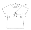
近年、スポーツ、健康管理、医療などの分野において、人の生体情報を取得するための手段として、被測定者の人体等からなる生体に装着して、生体から検知した生体信号の計測を行う生体信号計測用衣服が普及しつつある。図6は、従来の生体信号計測用衣服の構成例である(非特許文献1)。図7は、従来の生体信号計測用衣服の変形例である(非特許文献1)。図8は、従来の生体信号計測用衣服の他の構成例である(非特許文献2)。 In recent years, in fields such as sports, health management, and medical care, as a means for acquiring human biological information, a biological body that is attached to a living body including a human body of a measurement subject and measures a biological signal detected from the living body Signal measurement clothing is becoming popular. FIG. 6 is a configuration example of a conventional biological signal measurement garment (Non-Patent Document 1). FIG. 7 shows a modification of the conventional clothing for measuring biosignals (Non-Patent Document 1). FIG. 8 shows another configuration example of a conventional biological signal measuring garment (Non-Patent Document 2).
図6〜図8に示すように、従来の生体信号計測用衣服50には、生体から生体信号を検出する生体電極51と、ウェアラブル機器(図示せず)を取り付けるためのコネクタ52と、これら生体電極51とコネクタ52とを電気的に接続するための信号配線53が配置されている。
ウェアラブル機器は、スマートフォンなどの小型の携帯端末装置からなり、生体電極51により検知した心電、心拍、筋電、呼吸波等の微弱な生体信号を電気信号に変換し、無線によって送信するものが知られている。
As shown in FIGS. 6 to 8, a conventional biological
The wearable device is composed of a small portable terminal device such as a smartphone, and converts a weak biological signal such as an electrocardiogram, a heartbeat, a myoelectricity, and a respiratory wave detected by the
しかしながら、非特許文献1に記載の生体信号計測用衣服50では、図6や図7に示したように、ウェアラブル機器を取り付けるコネクタ52が衣服の左肩あるいはその近傍に配置されているため、このような配置の場合には、肩の表面や近傍に物体が存在する状況、例えばヴァイオリンの演奏時において、ウェアラブル機器がヴァイオリン筐体を置く妨げになり、また、アーチェリーにおいては、引いた弦が戻る際に左肩近傍を通過するため、ウェアラブル機器に衝突してしまうという問題点があった。
However, in the biological
また、非特許文献2に記載の生体信号計測用衣服50では、図8に示したように、ウェアラブル機器を取り付けるコネクタ52が衣服の中央、すなわち胴体の胸部に配置されているため、このような配置の場合には、胸部が外部と接触する状況、例えばサッカーにおいて、ボールを胸でトラップしようとした際に、ボールと機器が衝突してしまうという問題点があった。
Further, in the biological
これらの課題の対処法としては、用途に応じてウェアラブル機器の取り付け位置の異なる生体信号計測用衣服を作製すればよい。しかし、利用者個々人に応じて用途は多種多様であり、用意すべき生体信号計測用衣服は膨大な種類となってしまい、多様な種類の生体信号計測用衣服を取り揃えておくための費用が増大することになる。このため、結局は、生体信号計測用衣服の製造コストが増大する原因となるという問題点がある。 As a method for dealing with these problems, it is only necessary to produce a garment for measuring biosignals in which the mounting position of the wearable device differs depending on the application. However, there are a wide variety of uses depending on the individual user, and there are a huge variety of biological signal measurement clothes to be prepared, which increases the cost of collecting various types of biological signal measurement clothes. Will do. For this reason, after all, there is a problem in that the manufacturing cost of the garment for measuring biological signals increases.
本発明の目的は、製造コストを増大させることなく、複数の異なる位置にウェアラブル機器を取り付けられる生体信号計測用衣服を提供することにある。 An object of the present invention is to provide a biological signal measuring garment in which a wearable device can be attached to a plurality of different positions without increasing the manufacturing cost.
このような目的を達成するために、本発明にかかる生体信号計測用衣服は、複数の接続端子を有し、被計測体となる生体から生体信号を検出する生体電極と、複数のコネクタレセプタクルを有するコネクタと、複数本の配線からなり、互いに対応する前記接続端子と前記コネクタレセプタクルとを、これら配線で電気的に個別に接続する信号配線とを備え、前記各配線は、前記生体電極および前記コネクタが配置される配置エリアにわたって蛇行し、かつ、互いにほぼ平行するよう配置されているものである。 In order to achieve such an object, a biological signal measuring garment according to the present invention has a plurality of connection terminals, a biological electrode for detecting a biological signal from a living body to be measured, and a plurality of connector receptacles. A connector having a plurality of wires, and the corresponding connection terminals and the signal receptacles that electrically connect the connector receptacles to each other by these wires, and each wire includes the biological electrode and the wire It is meandering over the arrangement area where the connector is arranged and arranged so as to be substantially parallel to each other.
また、本発明にかかる他の生体信号計測用衣服は、複数の接続端子を有し、被計測体となる生体から生体信号を検出する生体電極と、複数のコネクタレセプタクルを有するコネクタと、複数本の配線からなり、互いに対応する前記接続端子と前記コネクタレセプタクルとを、これら配線で電気的に個別に接続する信号配線とを備え、前記各配線は、前記生体電極および前記コネクタが配置される配置エリアにわたり、互いに噛み合うように櫛形に配置されているものである。 Also, other biological signal measuring garment according to the present invention, a connection terminal of the multiple, the bioelectrode for detecting a biosignal from a living body to be measured object, a connector having a plurality of connector receptacle, a plurality Signal wiring for electrically connecting the connection terminals and the connector receptacles corresponding to each other electrically with these wirings, and each of the wirings is provided with the biological electrode and the connector. They are arranged in a comb shape so as to mesh with each other over the arrangement area.
また、本発明にかかる上記生体信号計測用衣服の一構成例は、前記信号配線が、3本以上の前記配線からなり、これら配線のうち、2つの配線が、前記生体電極および前記コネクタが配置される配置エリアの全域にわたり、互いに噛み合うように櫛形に配置されており、余の配線が、前記2つの配線の間に蛇行するよう配置されているものである。 Also, in one configuration example of the biological signal measurement garment according to the present invention, the signal wiring includes three or more wirings, and two of the wirings are arranged by the biological electrode and the connector. The entire arrangement area is arranged in a comb shape so as to mesh with each other, and the remaining wiring is arranged to meander between the two wirings.
また、本発明にかかる上記生体信号計測用衣服の一構成例は、前記コネクタが、ウェアラブル機器の取り付け候補となる複数位置に配置されているものである。 Moreover, one structural example of the said biological signal measurement clothes concerning this invention is arrange | positioned at the several position used as the attachment candidate of a wearable apparatus.
また、本発明にかかる上記生体信号計測用衣服の一構成例は、前記信号配線が、導電性を有するインク配線からなるものである。 Also, in one configuration example of the biological signal measurement garment according to the present invention, the signal wiring is made of conductive ink wiring.
また、本発明にかかる上記生体信号計測用衣服の一構成例は、前記コネクタおよび/または前記信号配線が、導電性を有する面ファスナーからなるものである。 Moreover, one structural example of the said biological signal measurement clothes concerning this invention consists of a hook-and-loop fastener in which the said connector and / or the said signal wiring have electroconductivity.
本発明によれば、生体信号計測用衣服において信号配線の配置を統一化できるため、コネクタの配置位置のみの変更で、様々な位置にウェアラブル機器を取り付けることができる。このため、生体信号計測用衣服に要請される多種多様な用途に容易に対応することができ、多様な種類の生体信号計測用衣服を取り揃えておくための費用を大幅に削減することが可能となる。また、コネクタの配置位置によらず、生体信号計測用衣服における信号配線の位置を固定化できるため、信号配線の仕様および作製工程を統一化することができる。このため、生体信号計測用衣服の製造コストを大幅に削減することが可能となる。
したがって、製造コストを増大させることなく、複数の異なる位置にウェアラブル機器を取り付けることが可能な生体信号計測用衣服を提供することができ、スポーツ、健康管理、医療などの幅広い分野において、人の生体情報を取得するための手段として、極めて有用である。
According to the present invention, since the arrangement of signal wiring can be unified in the garment for measuring biological signals, the wearable device can be attached to various positions by changing only the arrangement position of the connector. For this reason, it is possible to easily cope with a wide variety of uses required for biological signal measurement clothes, and it is possible to greatly reduce the cost for collecting various types of biological signal measurement clothes. Become. In addition, since the position of the signal wiring in the biological signal measurement garment can be fixed regardless of the position of the connector, the specification of the signal wiring and the manufacturing process can be unified. For this reason, it becomes possible to reduce significantly the manufacturing cost of the biological signal measurement clothes.
Therefore, it is possible to provide a biological signal measurement garment capable of attaching a wearable device to a plurality of different positions without increasing manufacturing costs, and in a wide range of fields such as sports, health care, and medical care, It is extremely useful as a means for acquiring information.
次に、本発明の実施の形態について図面を参照して説明する。
[第1の実施の形態]
まず、図1および図2を参照して、本発明の第1の実施の形態にかかる生体信号計測用衣服について説明する。図1は、第1の実施の形態にかかる生体信号計測用衣服の構成例である。図2は、第1の実施の形態にかかる生体信号計測用衣服の変形例である。
Next, embodiments of the present invention will be described with reference to the drawings.
[First Embodiment]
First, with reference to FIG. 1 and FIG. 2, the biological signal measurement clothes according to the first embodiment of the present invention will be described. FIG. 1 is a configuration example of a biological signal measurement garment according to the first embodiment. FIG. 2 is a modification of the biological signal measurement garment according to the first embodiment.
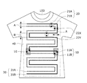
この生体信号計測用衣服100は、被計測体となる生体から生体信号を検出する生体電極10に設けられている複数の接続端子11と、ウェアラブル機器(図示せず)を取り付けるコネクタ20に設けられている複数のコネクタレセプタクル21とを、それぞれの接続端子11およびコネクタレセプタクル21の信号種別ごとに、独立した個別の個別配線(配線)31で電気的に接続する信号配線30を備えている。
The
本実施の形態にかかる生体信号計測用衣服100は、信号配線30の各個別配線31を、生体電極10およびコネクタ20が配置される配置エリア40の全域にわたって蛇行し、かつ、互いに平行するよう配置したものである。なお、蛇行の方向については、横方向に限定されるものではなく、縦方向や斜め方向など、他の方向であってもよい。
In the biological
また、生体電極10については、例えば非特許文献1,2に記載されている「hiteo」などの公知の機能素材を用いて、生体信号計測用衣服100の生地に形成すればよい。また、信号配線30については、例えば縫製可能な公知の導電性糸を用いて、生体信号計測用衣服100の生地に縫製すればよい。また、配置エリア40については、生体のうち生体信号の計測位置に応じて、適宜設定すればよい。
The
本実施の形態では、図1および図2に示すように、接続端子11およびコネクタレセプタクル21は、1つの生体電極10およびコネクタ20あたり2個もしくは3個の場合を例とする。その理由は次のようになる。例えば、1か所の誘導位置によって心臓の拍動に伴う心筋の活動電位(心電)を計測する場合、ウェアラブル機器が差動入力電圧をもって心電を検出する際にはプラスとマイナスの2つの電極があればよく、接続端子11およびコネクタレセプタクル21もこれらの電極と同じ数があればよい。
In the present embodiment, as shown in FIGS. 1 and 2, two or three connection terminals 11 and connector receptacles 21 are used as one
一方、差動入力ではなく、グラウンド(接地電位)を設けて基準電位との差により心電を検出する場合は、プラスとマイナスに加えてグラウンドの計3つの検出電極があればよく、接続端子11およびコネクタレセプタクル21もこれと同数あればよいためである。1誘導であってもウェアラブル機器が4つ以上のコネクタプラグを具備する場合はあり得るが、4番目からのコネクタプラグは単なる固定具として働くなど、電気回路的機能的に必須ではない働きをすると推測され、個別配線31との接続を必要としないからである。 On the other hand, in the case where an electrocardiogram is detected based on the difference from the reference potential by providing a ground (ground potential) instead of a differential input, it is sufficient to have a total of three detection electrodes in addition to plus and minus. 11 and the connector receptacles 21 need only be the same number. Even in the case of one lead, the wearable device may have four or more connector plugs, but the connector plugs from the fourth act as a mere fixture, etc. This is because it is assumed that connection with the individual wiring 31 is not required.
図1の構成例において、生体電極10は、配置エリア40のうち、身体の正中線を境に左右1つずつ胴部の生体と接するように配置されている。生体電極10とコネクタ20とを接続する個別配線31は2本あり、各個別配線31A,31Bに対して、それぞれ対応する、各コネクタ20のコネクタレセプタクル21A,21B、および各生体電極10の接続端子11A,11Bが、個別に接続されている。
In the configuration example of FIG. 1, the
また、各個別配線31A,31Bは互いに交差せず、特定の間隔Aと間隔Bを隔てて、配置エリア40の全域にわたり蛇行しながら平行して配置されている。異なる個別配線31A,31B間の間隔Aはウェアラブル機器のコネクタプラグの間隔と同じであり、例えば4.6cmとする。一方、同一個別配線31A,31B間の間隔Bはウェアラブル機器のコネクタプラグが取り付けられない間隔とし、4.6cmより短いか長い距離とする。
Further, the
例えば、間隔Bは5.6cmとする。コネクタレセプタクル21については、ウェアラブル機器が備える2つのコネクタプラグ間の距離と同じ距離を隔てて、1組のコネクタレセプタクル21が個別配線31上に配置する。
これにより、コネクタ20は、個別配線31A,31Bの両方が存在する位置22Xに配置可能となり、個別配線31A,31Bのいずれかが存在しない位置、例えば個別配線31Bが存在しない位置22Yに配置しても、誤配線を回避できる。
For example, the interval B is 5.6 cm. As for the connector receptacle 21, one set of connector receptacles 21 is arranged on the individual wiring 31 with the same distance as the distance between two connector plugs included in the wearable device.
Accordingly, the
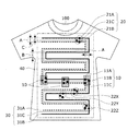
図2の変形例では、生体電極10が3つ配置されており、身体の正中線を境に左右1つずつ胴部の生体と接するように配置され2つに加え、正中線近傍に1つ配置されている。生体電極10とコネクタ20とを接続する個別配線31は3本あり、各個別配線31A,31B,31Cに対して、それぞれ対応する、各コネクタ20のコネクタレセプタクル21A,21B,21C、および各生体電極10の接続端子11A,11B,11Cが、個別に接続されている。
In the modification of FIG. 2, three
また、各個別配線31A,31B,31Cは互いに交差せず、特定の間隔A、間隔B、間隔Cを隔てて、配置エリア40の全域にわたり蛇行しながら平行して配置されている。間隔Aおよび間隔Bは図1と同じであり、個別配線31B,31C間の間隔Cはウェアラブル機器のコネクタプラグの三角形の形状に合うように設計される。例えば間隔Cは4.3cmとする。
これにより、コネクタ20は、個別配線31A,31B,31Cのすべてが存在する位置22X,22Zに配置可能となり、個別配線31A,31B,31Cのいずれかが存在しない位置、例えば個別配線31B,31Cが存在しない位置22Yに配置しても、誤配線は回避される。
The
As a result, the
[第1の実施の形態の効果]
このように、本実施の形態は、生体電極10とコネクタ20とを接続する信号配線30の各個別配線31を、生体電極10およびコネクタ20が配置される配置エリア40の全域にわたり、蛇行かつ平行するよう形成したものである。
これにより、コネクタ20が配置エリア40のうち左肩以外に置かれる場合においても、その配置場所を通過する個別配線31にそれぞれのコネクタレセプタクル21を接続できる。
[Effect of the first embodiment]
As described above, in the present embodiment, the individual wirings 31 of the
As a result, even when the
したがって、生体信号計測用衣服100において信号配線30の配置を統一化できるため、コネクタ20の配置位置のみの変更で、様々な位置にウェアラブル機器を取り付けることができる。このため、生体信号計測用衣服100に要請される多種多様な用途に容易に対応することができ、多様な種類の生体信号計測用衣服100を取り揃えておくための費用を大幅に削減することが可能となる。
Therefore, since the arrangement of the
また、コネクタ20の配置位置によらず、生体信号計測用衣服100における信号配線30の位置を固定化できるため、信号配線30の仕様および作製工程を統一化することができる。このため、生体信号計測用衣服100の製造コストを大幅に削減することが可能となる。
したがって、本発明によれば、製造コストを増大させることなく、複数の異なる位置にウェアラブル機器を取り付けることが可能な生体信号計測用衣服を提供することができ、スポーツ、健康管理、医療などの幅広い分野において、人の生体情報を取得するための手段として、極めて有用である。
Moreover, since the position of the
Therefore, according to the present invention, it is possible to provide a garment for measuring a biosignal capable of attaching a wearable device to a plurality of different positions without increasing manufacturing costs, and a wide range of sports, health care, medical care, and the like. In the field, it is extremely useful as a means for acquiring human biological information.
[第2の実施の形態]
次に、図3を参照して、本発明の第2の実施の形態にかかる生体信号計測用衣服100について説明する。図3は、第2の実施の形態にかかる生体信号計測用衣服の構成例である。
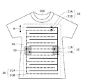
第2の実施の形態は、第1の実施の形態の変形例であり、信号配線30の個別配線31を、前述の蛇行配置に代えて、生体電極10およびコネクタ20が配置される配置エリア40の全域にわたり、互いに噛み合うように櫛形に配置したことを特徴とする。
[Second Embodiment]
Next, a biological
The second embodiment is a modification of the first embodiment, in which the individual wiring 31 of the
図3において、生体電極10とコネクタ20とを接続する個別配線31は2本あり、各個別配線31A,31Bに対して、それぞれ対応する、各コネクタ20のコネクタレセプタクル21A,21B、および各生体電極10の接続端子11A,11Bが、個別に接続されている。
In FIG. 3, there are two individual wires 31 for connecting the
この際、信号配線30の各個別配線31(31A,31B)は、交差することなく互いに噛み合うように、それぞれ櫛形に配置されている。なお、櫛形の方向については、横方向に限定されるものではなく、縦方向や斜め方向など、他の方向であってもよい。
これにより、第1の実施の形態にかかる間隔Bが不要になり、同じ面積内において間隔Aで構成される平行線の繰り返し回数が増えるため、より細かく取り付け位置を選択することができる。
At this time, the individual wirings 31 (31A, 31B) of the
Thereby, the interval B according to the first embodiment is not necessary, and the number of repetitions of the parallel lines formed by the interval A within the same area is increased, so that the attachment position can be selected more finely.
これら個別配線31(31A,31B)は、互いに特定の間隔A(cm)を隔てて配置されている。間隔Aはウェアラブル機器のコネクタプラグの間隔と同じであり、例えば4.6cmとする。
本実施の形態によれば、コネクタ20は、個別配線31A,31Bの両方が存在する位置に配置可能となり、個別配線31A,31Bのいずれかが存在しない位置には配置しても、誤配線は回避される。
These individual wirings 31 (31A, 31B) are arranged at a specific distance A (cm) from each other. The distance A is the same as the distance between the connector plugs of the wearable device, for example, 4.6 cm.
According to the present embodiment, the
[第3の実施の形態]
次に、図4を参照して、本発明の第3の実施の形態にかかる生体信号計測用衣服100について説明する。図4は、第3の実施の形態にかかる生体信号計測用衣服の構成例である。
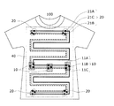
第3の実施の形態は、第1および第2の実施の形態の変形例であり、信号配線30が3本以上の個別配線31からなり、これら個別配線31のうち、2つの個別配線31A,31Bが、生体電極10およびコネクタ20が配置される配置エリア40の全域にわたり、互いに噛み合うように櫛形に配置されており、余の個別配線31Cが、2つの個別配線31A,31Bの間に蛇行するよう配置したことを特徴とする。
[Third Embodiment]
Next, a biological
The third embodiment is a modification of the first and second embodiments, and the
図4において、接続端子11A,11Bおよびコネクタレセプタクル21A,21Bと接続される個別配線31A,31Bは櫛形を成し、接続端子11Cおよびコネクタレセプタクル21Cと接続される個別配線31Cは蛇行し、かつ、個別配線31A,31Bと平行するよう配置されている。なお、蛇行および櫛形の方向については、横方向に限定されるものではなく、縦方向や斜め方向など、他の方向であってもよい。
In FIG. 4, the
また、個別配線31A,31B間の間隔Aおよび個別配線31B,31C間の間隔Cは第2に実施の形態と同様とする。
本実施の形態によれば、第1の実施の間隔Bが存在しないため、3個のコネクタレセプタクル21を持つコネクタ20を用いる場合においても、第2の実施の形態と同様の効果が実現できる。
The interval A between the
According to the present embodiment, since the interval B of the first embodiment does not exist, even when the
[第4の実施の形態]
次に、図5を参照して、本発明の第4の実施の形態にかかる生体信号計測用衣服100について説明する。図5は、第4の実施の形態にかかる生体信号計測用衣服の構成例である。
第4の実施の形態は、第1〜第3の実施の形態の変形例であり、コネクタ20を、ウェアラブル機器の取り付け候補となる複数位置したことを特徴とする。
[Fourth Embodiment]
Next, a biological
The fourth embodiment is a modification of the first to third embodiments, and is characterized in that a plurality of
図5において、両腕に近い肩部、両脚に近い脇腹部、および胴体の中央に近いみぞおち部からなる、ウェアラブル機器の取り付け候補の位置に、合計5つのコネクタ20が配置されており、各個別配線31A,31B,31Cに対して、それぞれ対応する、各コネクタ20のコネクタレセプタクル21A,21B,21C、および各生体電極10の接続端子11A,11B,11Cが、個別に接続されている。
本実施の形態によれば、予め設定したウェアラブル機器の取り付け候補の位置にコネクタ20が配置されているため、利用者は用途に応じて最適なコネクタ20を選択し、使用することが可能となる。
In FIG. 5, a total of five
According to the present embodiment, since the
[第5の実施の形態]
次に、本発明の第5の実施の形態にかかる生体信号計測用衣服100について説明する。第5の実施の形態にかかる生体信号計測用衣服100は、信号配線30として、導電性を持つインク配線を用いたことを特徴とする。衣服に印刷できる導電性材料の例は、非特許文献3に記載されている。
本実施の形態によれば、信号配線30を形成する場合に生じる導電性糸の衣服への裁縫が不要になり、配線作製工程を容易化できるため、生体信号計測用衣服の製造コストを廉価にすることができる。
[Fifth Embodiment]
Next, a biological
According to the present embodiment, it is not necessary to sew the conductive yarn generated when forming the
[第6の実施の形態]
次に、本発明の第6の実施の形態にかかる生体信号計測用衣服100について説明する。第6の実施の形態にかかる生体信号計測用衣服100は、コネクタ20および/または信号配線30として、導電性を有する面ファスナーを用いることを特徴とする。導電性の面ファスナーとしては、非特許文献4に記載されている。
本実施の形態によれば、コネクタ20のコネクタレセプタクル21が、面ファスナーに置き換わるため、利用者はコネクタ20の位置に限定されず、面ファスナーが配置されている任意の位置にウェアラブル機器を取り付けることができる。
[Sixth Embodiment]
Next, a biological
According to the present embodiment, since the connector receptacle 21 of the
[実施の形態の拡張]
以上、実施形態を参照して本発明を説明したが、本発明は上記実施形態に限定されるものではない。本発明の構成や詳細には、本発明のスコープ内で当業者が理解しうる様々な変更をすることができる。また、各実施形態については、矛盾しない範囲で任意に組み合わせて実施することができる。
[Extended embodiment]
The present invention has been described above with reference to the embodiments, but the present invention is not limited to the above embodiments. Various changes that can be understood by those skilled in the art can be made to the configuration and details of the present invention within the scope of the present invention. In addition, each embodiment can be implemented in any combination within a consistent range.
100…生体信号計測用衣服、10…生体電極、11,11A,11B,11C…接続端子、20…コネクタ、21,21A,21B,21C…コネクタレセプタクル、22X,22Y,22Z…位置、30…信号配線、31,31A,31B,31C…個別配線、40…配置エリア。
DESCRIPTION OF
Claims (6)
複数のコネクタレセプタクルを有するコネクタと、
複数本の配線からなり、互いに対応する前記接続端子と前記コネクタレセプタクルとを、これら配線で電気的に個別に接続する信号配線とを備え、
前記各配線は、前記生体電極および前記コネクタが配置される配置エリアにわたって蛇行し、かつ、互いにほぼ平行するよう配置されている
ことを特徴とする生体信号計測用衣服。 A biological electrode that has a plurality of connection terminals and detects a biological signal from a biological body to be measured;
A connector having a plurality of connector receptacles;
A plurality of wirings, each of the connection terminals corresponding to each other and the connector receptacle are provided with signal wirings that are electrically connected individually by these wirings,
Each of the wirings meanders over an arrangement area where the bioelectrode and the connector are arranged, and is arranged so as to be substantially parallel to each other.
複数のコネクタレセプタクルを有するコネクタと、
複数本の配線からなり、互いに対応する前記接続端子と前記コネクタレセプタクルとを、これら配線で電気的に個別に接続する信号配線とを備え、
前記各配線は、前記生体電極および前記コネクタが配置される配置エリアにわたり、互いに噛み合うように櫛形に配置されている
ことを特徴とする生体信号計測用衣服。 It has a multiple connection terminals, and the biological electrodes for detecting a biosignal from a living body to be measured object,
A connector having a plurality of connector receptacles;
A plurality of wirings, each of the connection terminals corresponding to each other and the connector receptacle are provided with signal wirings that are electrically connected individually by these wirings,
Each said wiring is arrange | positioned at the comb shape so that it may mutually mesh | engage over the arrangement | positioning area where the said bioelectrode and the said connector are arrange | positioned. The clothes for biosignal measurement characterized by the above-mentioned.
前記信号配線は、3本以上の前記配線からなり、これら配線のうち、2つの配線が、前記生体電極および前記コネクタが配置される配置エリアの全域にわたり、互いに噛み合うように櫛形に配置されており、余の配線が、前記2つの配線の間に蛇行するよう配置されている
ことを特徴とする生体信号計測用衣服。 The biological signal measurement garment according to claim 2,
The signal wiring is composed of three or more wirings, and of these wirings, two wirings are arranged in a comb shape so as to mesh with each other over the entire arrangement area where the biological electrode and the connector are arranged. The surplus wiring is arranged so as to meander between the two wirings.
前記コネクタは、ウェアラブル機器の取り付け候補となる複数位置に配置されていることを特徴とする生体信号計測用衣服。 In the biological signal measurement garment according to any one of claims 1 to 3,
The biological signal measuring garment, wherein the connector is arranged at a plurality of positions that are candidates for attachment of a wearable device.
前記信号配線は、導電性を有するインク配線からなることを特徴とする生体信号計測用衣服。 In the garment for measuring biological signals according to any one of claims 1 to 4,
The clothing for measuring biosignals, wherein the signal wiring is made of conductive ink wiring.
前記コネクタおよび/または前記信号配線は、導電性を有する面ファスナーからなることを特徴とする生体信号計測用衣服。 In the garment for measuring biological signals according to any one of claims 1 to 4,
The biological signal measuring garment, wherein the connector and / or the signal wiring is made of a conductive surface fastener.
Priority Applications (1)
| Application Number | Priority Date | Filing Date | Title |
|---|---|---|---|
| JP2015010932A JP6235501B2 (en) | 2015-01-23 | 2015-01-23 | Biological signal measurement clothing |
Applications Claiming Priority (1)
| Application Number | Priority Date | Filing Date | Title |
|---|---|---|---|
| JP2015010932A JP6235501B2 (en) | 2015-01-23 | 2015-01-23 | Biological signal measurement clothing |
Publications (3)
| Publication Number | Publication Date |
|---|---|
| JP2016136456A JP2016136456A (en) | 2016-07-28 |
| JP2016136456A5 JP2016136456A5 (en) | 2017-11-09 |
| JP6235501B2 true JP6235501B2 (en) | 2017-11-22 |
Family
ID=56512697
Family Applications (1)
| Application Number | Title | Priority Date | Filing Date |
|---|---|---|---|
| JP2015010932A Active JP6235501B2 (en) | 2015-01-23 | 2015-01-23 | Biological signal measurement clothing |
Country Status (1)
| Country | Link |
|---|---|
| JP (1) | JP6235501B2 (en) |
Families Citing this family (2)
| Publication number | Priority date | Publication date | Assignee | Title |
|---|---|---|---|---|
| JP6876360B2 (en) * | 2017-04-03 | 2021-05-26 | 株式会社テクサー | Electrodes for biological signal measuring devices and biological signal measuring devices equipped with them |
| JP7352839B2 (en) | 2018-07-13 | 2023-09-29 | 東洋紡株式会社 | Clothes-type electronic equipment and its manufacturing method |
Family Cites Families (4)
| Publication number | Priority date | Publication date | Assignee | Title |
|---|---|---|---|---|
| JP2000148290A (en) * | 1998-11-06 | 2000-05-26 | Internatl Business Mach Corp <Ibm> | Information processing system |
| WO2009041496A1 (en) * | 2007-09-25 | 2009-04-02 | Dainippon Sumitomo Pharma Co., Ltd. | Electrode sheet and process for producing electrode sheet |
| JP2011056034A (en) * | 2009-09-10 | 2011-03-24 | Boson Technology Co Ltd | Sportswear for measuring physiological situation |
| EP2696752B1 (en) * | 2011-04-12 | 2019-12-04 | Smart Solutions Technologies, S.L. | Fabric for acquiring physiological signals |
-
2015
- 2015-01-23 JP JP2015010932A patent/JP6235501B2/en active Active
Also Published As
| Publication number | Publication date |
|---|---|
| JP2016136456A (en) | 2016-07-28 |
Similar Documents
| Publication | Publication Date | Title |
|---|---|---|
| CN108024721B (en) | Flexible fabric strap connector for garment with sensors and electronics | |
| JP5926776B2 (en) | ELECTRODE DEVICE FOR MEASURING IMPEDUS IN THE HUMAN BODY, AND DEVICE FOR MEASURING AND TREATING TREATMENT USING IT | |
| Linz et al. | Contactless EMG sensors embroidered onto textile | |
| JP6749698B2 (en) | Connector board, sensor system and wearable sensor system | |
| US20180043151A1 (en) | Biological electrode and biological electrode-equipped wearing tool | |
| US10530083B2 (en) | Printed circuit board biosensing garment connector | |
| EP2803315A1 (en) | Heart activity sensor structure | |
| WO2013152094A1 (en) | Disposable low-profile conformable biomedical sensor | |
| WO2012046237A3 (en) | Device for use in electro-biological signal measurement in the presence of a magnetic field | |
| CN205512398U (en) | Human biological electricity monitoring brassiere | |
| EP3549515A1 (en) | Electrode belt device for measuring bio-signal | |
| JP7267418B2 (en) | Multi-sensor resistance textile ECG system | |
| JP6235501B2 (en) | Biological signal measurement clothing | |
| JP2016158912A (en) | Clothing, biometric signal measurement device, and biometric signal detection member | |
| RU2678542C1 (en) | Planar magnetic resonance safe cable for biopotential measurements | |
| CN110198669A (en) | For measuring the fabric device of the bioelectrical activity of subject | |
| US11642062B2 (en) | Production of electrical contact with skin | |
| KR20130141288A (en) | Clothes comprising a band sensor | |
| JP2016136456A5 (en) | ||
| CN204991202U (en) | Flexible electrically conductive cable | |
| CN205514589U (en) | Close -fitting underwear is used in guardianship of intelligence electrocardio | |
| EP3231357B1 (en) | Emi protection for physiological measurements | |
| US20210219895A1 (en) | Wearable muscle activity sensor and electrode | |
| Catarino et al. | Integration of biosignal monitoring in sports clothing | |
| KR20200067816A (en) | Smart Clothes |
Legal Events
| Date | Code | Title | Description |
|---|---|---|---|
| A621 | Written request for application examination |
Free format text: JAPANESE INTERMEDIATE CODE: A621 Effective date: 20170111 |
|
| A977 | Report on retrieval |
Free format text: JAPANESE INTERMEDIATE CODE: A971007 Effective date: 20170921 |
|
| A521 | Written amendment |
Free format text: JAPANESE INTERMEDIATE CODE: A523 Effective date: 20170929 |
|
| TRDD | Decision of grant or rejection written | ||
| A01 | Written decision to grant a patent or to grant a registration (utility model) |
Free format text: JAPANESE INTERMEDIATE CODE: A01 Effective date: 20171024 |
|
| A61 | First payment of annual fees (during grant procedure) |
Free format text: JAPANESE INTERMEDIATE CODE: A61 Effective date: 20171026 |
|
| R150 | Certificate of patent or registration of utility model |
Ref document number: 6235501 Country of ref document: JP Free format text: JAPANESE INTERMEDIATE CODE: R150 |