JP6234414B2 - Electronic brake support system for use when a service brake system fails or deteriorates - Google Patents
Electronic brake support system for use when a service brake system fails or deteriorates Download PDFInfo
- Publication number
- JP6234414B2 JP6234414B2 JP2015186320A JP2015186320A JP6234414B2 JP 6234414 B2 JP6234414 B2 JP 6234414B2 JP 2015186320 A JP2015186320 A JP 2015186320A JP 2015186320 A JP2015186320 A JP 2015186320A JP 6234414 B2 JP6234414 B2 JP 6234414B2
- Authority
- JP
- Japan
- Prior art keywords
- brake
- vehicle
- service brake
- parking brake
- service
- Prior art date
- Legal status (The legal status is an assumption and is not a legal conclusion. Google has not performed a legal analysis and makes no representation as to the accuracy of the status listed.)
- Active
Links
- 238000000034 method Methods 0.000 claims description 15
- 238000012545 processing Methods 0.000 claims description 5
- 230000006866 deterioration Effects 0.000 claims description 4
- 230000003247 decreasing effect Effects 0.000 claims description 3
- 230000003213 activating effect Effects 0.000 claims 1
- 238000012544 monitoring process Methods 0.000 claims 1
- 230000002265 prevention Effects 0.000 description 3
- 238000003491 array Methods 0.000 description 2
- 230000015556 catabolic process Effects 0.000 description 2
- 238000006731 degradation reaction Methods 0.000 description 2
- 238000010586 diagram Methods 0.000 description 2
- 238000011156 evaluation Methods 0.000 description 2
- 239000010720 hydraulic oil Substances 0.000 description 2
- 230000005540 biological transmission Effects 0.000 description 1
- 239000002131 composite material Substances 0.000 description 1
- 238000007796 conventional method Methods 0.000 description 1
- 238000001514 detection method Methods 0.000 description 1
- 238000004519 manufacturing process Methods 0.000 description 1
- 238000012986 modification Methods 0.000 description 1
- 230000004048 modification Effects 0.000 description 1
- 238000004806 packaging method and process Methods 0.000 description 1
Images

Classifications
-
- B—PERFORMING OPERATIONS; TRANSPORTING
- B60—VEHICLES IN GENERAL
- B60T—VEHICLE BRAKE CONTROL SYSTEMS OR PARTS THEREOF; BRAKE CONTROL SYSTEMS OR PARTS THEREOF, IN GENERAL; ARRANGEMENT OF BRAKING ELEMENTS ON VEHICLES IN GENERAL; PORTABLE DEVICES FOR PREVENTING UNWANTED MOVEMENT OF VEHICLES; VEHICLE MODIFICATIONS TO FACILITATE COOLING OF BRAKES
- B60T17/00—Component parts, details, or accessories of power brake systems not covered by groups B60T8/00, B60T13/00 or B60T15/00, or presenting other characteristic features
- B60T17/18—Safety devices; Monitoring
- B60T17/22—Devices for monitoring or checking brake systems; Signal devices
-
- B—PERFORMING OPERATIONS; TRANSPORTING
- B60—VEHICLES IN GENERAL
- B60T—VEHICLE BRAKE CONTROL SYSTEMS OR PARTS THEREOF; BRAKE CONTROL SYSTEMS OR PARTS THEREOF, IN GENERAL; ARRANGEMENT OF BRAKING ELEMENTS ON VEHICLES IN GENERAL; PORTABLE DEVICES FOR PREVENTING UNWANTED MOVEMENT OF VEHICLES; VEHICLE MODIFICATIONS TO FACILITATE COOLING OF BRAKES
- B60T7/00—Brake-action initiating means
- B60T7/12—Brake-action initiating means for automatic initiation; for initiation not subject to will of driver or passenger
-
- B—PERFORMING OPERATIONS; TRANSPORTING
- B60—VEHICLES IN GENERAL
- B60T—VEHICLE BRAKE CONTROL SYSTEMS OR PARTS THEREOF; BRAKE CONTROL SYSTEMS OR PARTS THEREOF, IN GENERAL; ARRANGEMENT OF BRAKING ELEMENTS ON VEHICLES IN GENERAL; PORTABLE DEVICES FOR PREVENTING UNWANTED MOVEMENT OF VEHICLES; VEHICLE MODIFICATIONS TO FACILITATE COOLING OF BRAKES
- B60T8/00—Arrangements for adjusting wheel-braking force to meet varying vehicular or ground-surface conditions, e.g. limiting or varying distribution of braking force
- B60T8/17—Using electrical or electronic regulation means to control braking
- B60T8/172—Determining control parameters used in the regulation, e.g. by calculations involving measured or detected parameters
-
- B—PERFORMING OPERATIONS; TRANSPORTING
- B60—VEHICLES IN GENERAL
- B60T—VEHICLE BRAKE CONTROL SYSTEMS OR PARTS THEREOF; BRAKE CONTROL SYSTEMS OR PARTS THEREOF, IN GENERAL; ARRANGEMENT OF BRAKING ELEMENTS ON VEHICLES IN GENERAL; PORTABLE DEVICES FOR PREVENTING UNWANTED MOVEMENT OF VEHICLES; VEHICLE MODIFICATIONS TO FACILITATE COOLING OF BRAKES
- B60T8/00—Arrangements for adjusting wheel-braking force to meet varying vehicular or ground-surface conditions, e.g. limiting or varying distribution of braking force
- B60T8/32—Arrangements for adjusting wheel-braking force to meet varying vehicular or ground-surface conditions, e.g. limiting or varying distribution of braking force responsive to a speed condition, e.g. acceleration or deceleration
- B60T8/88—Arrangements for adjusting wheel-braking force to meet varying vehicular or ground-surface conditions, e.g. limiting or varying distribution of braking force responsive to a speed condition, e.g. acceleration or deceleration with failure responsive means, i.e. means for detecting and indicating faulty operation of the speed responsive control means
Description
本発明は、常用ブレーキを備えた車両に関し、具体的には、常用ブレーキシステムが故障または劣化した場合に制動トルクを供給するのに使用できる電子パーキングブレーキ支援システムに関する。 The present invention relates to a vehicle equipped with a service brake, and more particularly to an electronic parking brake support system that can be used to supply braking torque when a service brake system fails or deteriorates.
常用ブレーキは劣化および故障する。このような劣化や故障が生じた車両は、相手先商標製品製造業者(OEM)により、または、たとえば米国(US)政府、欧州諸共同体委員会(ECE)等の法的主体により制定された最低所要性能を満たさなければならない。米国連邦自動車安全基準(FMVSS)135は、幾つかの車両最低所要性能の概要を定めており、この最低所要性能には、たとえば以下のものが含まれる:
・低温時有効性(ブレーキライニングの有効性低下)
・アンチロック機能故障(アンチロックブレーキシステム(ABS)における油圧ポンプまたはタイヤ内圧アウトレットバルブの故障、油圧制御ユニットの故障)
・油圧回路故障(1次側、2次側、またはその両方)
・軸出力ユニットまたは軸出力アシストユニットの機能不能(真空度が低いかまたは無い)
・高温性能(ブレーキライニングの有効性低下)
常用ブレーキシステムは、車両最低所要性能を満たすのに適した制動トルクを供給するように構成することができる。その例として、ペダル比を大きくすること、ライニングの摩擦を大きくすること、ブースタ直径を大きくすること、ロータを大きくすること、マスタシリンダ内径を小さくすること等が含まれる。車両最低所要性能を満たすためにブレーキトルクを増大させる制動トルク支援機能は他にも存在する。その例として、ブレーキブースタの真空を上昇させる電動真空ポンプ(EVP)や、ABS/横滑り防止制御ポンプが含まれる。上記の可能な解決手段には、重量、封止パッケージ、耐久性、コストおよび他の常用ブレーキ性能と、望ましくない主観的なブレーキ感覚特性についての妥協とが、必然的に関わってくる場合がある。
Service brakes deteriorate and fail. Vehicles with such deterioration or failure are the minimum established by the original equipment manufacturer (OEM) or by legal entities such as the United States (US) government, European Community Commission (ECE), etc. The required performance must be met. The Federal Motor Vehicle Safety Standard (FMVSS) 135 outlines several minimum vehicle performance requirements, including, for example, the following:
・ Effectiveness at low temperatures (decrease in effectiveness of brake lining)
・ Anti-lock function failure (failure of hydraulic pump or tire internal pressure outlet valve in anti-lock brake system (ABS), failure of hydraulic control unit)
・ Hydraulic circuit failure (primary side, secondary side, or both)
・ The function of the shaft output unit or shaft output assist unit is disabled (the degree of vacuum is low or not)
・ High temperature performance (decrease in effectiveness of brake lining)
The service brake system can be configured to provide a braking torque suitable to meet the minimum vehicle performance requirements. Examples include increasing the pedal ratio, increasing the lining friction, increasing the booster diameter, increasing the rotor, decreasing the master cylinder inner diameter, and the like. There are other braking torque support functions that increase the brake torque to meet the minimum required vehicle performance. Examples include an electric vacuum pump (EVP) that raises the vacuum of the brake booster and an ABS / side-slip prevention control pump. The possible solutions described above may necessarily involve weight, sealed packaging, durability, cost and other service brake performance, and compromise on undesirable subjective brake feel characteristics. .
よって、常用ブレーキが劣化または故障した場合に最低所要性能を満たすための制動トルクを供給するシステムであって、既存のブレーキシステム構成要素を使用し、重量を増加させることがなく、また、常用ブレーキ性能と主観的なブレーキ感覚特性との間で妥協しないシステムを実現する必要がある。 Therefore, it is a system that supplies braking torque to meet the minimum required performance when the service brake deteriorates or breaks down, uses existing brake system components, does not increase weight, and service brake There is a need to realize a system that does not compromise between performance and subjective brake feel characteristics.
本発明の課題は、上記にて挙げた要求を満たすことである。 The object of the present invention is to satisfy the requirements listed above.
本発明の基本的構成によれば、前記課題は、電動パーキングブレーキを含む車両用の電子パーキングブレーキ支援システムであって、当該電動パーキングブレーキは、当該車両のホイールに対して設けられた少なくとも1つのブレーキ部材を有する電子パーキングブレーキ支援システムにより解決される。前記システムはさらに、前記車両の常用ブレーキを制御するために構成および配置された常用ブレーキシステムも含む。前記常用ブレーキシステムは、当該常用ブレーキシステムの故障状態または劣化状態の発生を判定するように構成および配置された少なくとも1つの回路を含み、当該回路は、検出した当該状態に応じて、前記少なくとも1つのブレーキ部材を作動させるように前記電動パーキングブレーキに指示する要求信号を当該電動パーキングブレーキへ送信するように構成されている。 According to the basic configuration of the present invention, the subject is an electronic parking brake support system for a vehicle including an electric parking brake, wherein the electric parking brake is provided for at least one of the wheels of the vehicle. This is solved by an electronic parking brake support system having a brake member. The system further includes a service brake system constructed and arranged to control the service brake of the vehicle. The service brake system includes at least one circuit configured and arranged to determine the occurrence of a failure state or a degradation state of the service brake system, the circuit depending on the detected state, the at least one circuit. A request signal for instructing the electric parking brake to operate one brake member is transmitted to the electric parking brake.
本願にて開示する実施形態はさらに、車両の常用ブレーキシステムが適正に動作していない場合に電動パーキングブレーキを使用する方法も対象としている。前記方法は、前記常用ブレーキシステムが劣化または故障したか否かを判定し、当該常用ブレーキシステムが劣化または故障している場合には、前記車両に制動トルクを加えるように前記電動パーキングブレーキを作動させる。 The embodiments disclosed herein are further directed to a method of using an electric parking brake when the vehicle's service brake system is not operating properly. The method determines whether the service brake system has deteriorated or failed and, if the service brake system has deteriorated or failed, activates the electric parking brake to apply braking torque to the vehicle. Let
添付の図面を参照して、以下の詳細な説明および添付の特許請求の範囲を参酌すれば、本発明の他の対象、特徴および特性、ならびに、構造の重要な要素の動作方法および機能、部品の組合せならびに製造の経済性がより明らかである。以下の詳細な説明、特許請求の範囲および図面はすべて、本願明細書の一部を成す。 Other objects, features and characteristics of the present invention, as well as methods and functions of operation of key elements of the structure, components, in view of the following detailed description and appended claims with reference to the accompanying drawings The economics of the combination as well as the manufacture are more apparent. The following detailed description, claims, and drawings are all part of the specification.
添付図面を参照して、以下の有利な実施形態の詳細な説明を読めば、本発明をより良好に理解できる。図面中、同様の符号が指す部品は、同様の部品である。 BRIEF DESCRIPTION OF THE DRAWINGS The invention can be better understood by reading the following detailed description of advantageous embodiments with reference to the accompanying drawings. In the drawings, parts denoted by the same reference numerals are the same parts.
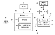
図1を参照すると、一実施形態の車両用の電子パーキングブレーキ支援システムのブロック図を示しており、当該電子パーキングブレーキ支援システムには全体として符号10を付している。当該システム10は常用ブレーキシステムを含んでおり、これには全体として符号11を付している。この常用ブレーキシステム11は、たとえば従来のアンチロックブレーキシステム(ABS)/横滑り防止制御ユニット等の電子制御ユニット(ECU)12を含む。前記システム10はさらに、従来の電動パーキングブレーキ(EPB)も含んでいる。この電動パーキングブレーキには全体として符号14を付しており、これは、前記常用ブレーキシステム11に関連付けられている。
Referring to FIG. 1, a block diagram of an electronic parking brake support system for a vehicle according to an embodiment is shown, and the electronic parking brake support system is denoted by
常用ブレーキシステム11は、従来の油圧式ブレーキシステムであるのが好適であるが、たとえばブレーキバイワイヤ型のブレーキシステム等の、任意のブレーキシステムとすることも可能である。前記制御ユニット12は、アクチュエータ26によって作動される常用ブレーキ27または少なくとも1つのホイールブレーキに対して設けられており、当該アクチュエータ26は制御装置12によって制御または調整される。図1に示す実施例では、1つのホイールブレーキ27が、これに属するアクチュエータ26と、当該ホイールブレーキ27に属する制御装置12とを備えているのが示されている。しかし、車両の各ホイールごとに、または他のホイールに対し、ホイールブレーキ27と、これに属するアクチュエータ26とを設けることができる。制御ユニット12は、(1つまたは複数の)アクチュエータ26の駆動をさせるため、当該(1つまたは複数の)アクチュエータ26に接続されている。センサ24からの車両入力情報と、たとえば運転者制動要求、スリップ制御システム(ABS:アンチロックシステム、TCS:トラクション制御システム)または運転支援システム(ESC:電子横滑り防止制御)の要求等の、制御ユニット12に存在する要求とに基づき、所望の制御モードについての決定が、制御ユニット12のプロセッサ25によってなされ、(1つまたは複数の)ホイールブレーキ27を制御するために(1つまたは複数の)アクチュエータ26へ従来の手法で伝送される。この従来の手法はたとえば、米国特許第8606477号明細書に記載されたものであり、同刊行物の記載内容は、引用により本願明細書の記載内容に含まれるものとする。
The
自動車用のEPB14は、有利には各ホイールごとに、アクチュエータ26とパーキングブレーキ部材27とを備えている。このパーキングブレーキ部材27はたとえば、当該ホイールの制動を引き起こすためのキャリパ等である。前記アクチュエータ26には、制御線路30を介してコントローラ28が接続されている。EPB14のある用途では、車両の運転者によるスイッチ32の駆動により、アクチュエータ26に関連付けられたブレーキ部材(たとえばキャリパ)27の非作動状態からの作動を当該アクチュエータ26にさせるための信号34が、コントローラ28へ送信される。他の用途では、スイッチ41の駆動により、アクチュエータ26に関連づけられたブレーキ部材27の作動または非作動化を当該アクチュエータ26にさせるための信号43が、コントローラ12へ送信される。EPB14は、個別のモータオンキャリパ方式を用いることができ、または、EPB14を複合ケーブルプラー型方式とすることができる。モータオンキャリパ方式、または、個別制御を行うことができる如何なる方式も有利であるのは、トラクションをより良好に最適化して車両安定性を制御できる独立した変更を行えるからである。
The EPB 14 for automobiles preferably includes an
1つの実施形態では、制御ユニット12は少なくとも1つのブレーキ状態評価回路を有する。このブレーキ状態評価回路はたとえば、常用ブレーキシステム11に関して故障状態または劣化状態が生じているか否かを判定する故障または劣化検出回路38等であり、これはたとえば、タイヤ内圧アウトレットバルブ故障等のアンチロック機能故障、アンチロックブレーキシステム(ABS)の油圧ポンプの故障、油圧制御ユニットの故障、油圧回路(1次側、2次側、または双方)の故障、軸出力ユニットの故障、軸出力アシストユニットの故障(真空が低いかまたは存在しない)、または、ブレーキライニングの性能(高温性能または低温性能)の低下の検出等を行う。これらのブレーキ状態は、センサ24によって監視し、処理回路25の論理回路によって評価することができ、前記回路38は、処理回路25によって評価されたこの情報を使用する。上述の状態のうちいずれかが回路38によって特定されると、当該回路38は、EPB14のブレーキ部材27の作動をアクチュエータ26にさせるための電子的要求信号40を、当該EPB14へ送信し、これにより、常用ブレーキシステム11の劣化または故障時には、車両に制動トルクが加えられ、当該制動トルクが最低所要性能を満たすように変化される。よって、このような状況においてEPB14を用いることにより、実現可能なトラクションが最適化され、車両安定性が維持される。また、ブレーキ部材(キャリパ)27が油圧式で操作される場合、制御ユニット12は、油圧路42を介して供給源からブレーキ部材27への作動油の供給を制御することができる。この作動油の供給の制御は一般的には、前記要求信号40の送信と同時に行われる。
In one embodiment, the
図2は、一実施形態の方法を実施するためのアルゴリズムを示すフローチャートである。ステップ44において、センサ24からの入力を使用し、かつ、前記制御ユニット12の回路38を用いて、車両状態を監視する。ステップ46は、回路38を用いて、常用ブレーキシステム11の故障または劣化が生じたか否か、または生じる過程であるか否かを判定する。そうでない場合には、ステップ48において、EPB14の作動を行わない。常用ブレーキシステム11の故障または劣化が判定された場合、ステップ50において、EPB14を作動させるための前記要求信号40をアクチュエータ26へ送信し、ステップ52において、当該EPB14はブレーキ部材27を介して制動トルクを加えて変化させる。制動トルクの変化は、たとえば車両減速、マスタシリンダ圧、ブースタ真空、車輪スリップ等の車両入力(センサ24により得られる)に基づくことができるが、これに限定されない。
FIG. 2 is a flowchart illustrating an algorithm for performing the method of one embodiment. In
システム10が使用するハードウェアは、すべて既存のものであり、重量が増加することはない。また、体積が増加する必要もない。上記システム10は、常用ブレーキ性能と、主観的なブレーキ感覚特性との間で妥協することもない。システム10はまた、たとえばABS/横滑り制御のポンプ支援等の他の追加的な制動トルク支援機能の代替的または補助的な手段の一部とすることもできる。
All hardware used by the
図1では、常用ブレーキはEPBのパーキングブレーキ部材27を含むことができ、または、常用ブレーキはEPBのパーキングブレーキ部材27に関連付けられているが、常用ブレーキをパーキングブレーキ部材27とは別個とすることも可能である。その際には、パーキングブレーキ部材27および常用ブレーキの双方を制御ユニット12によって制御することができる。
In FIG. 1, the service brake can include an EPB
ここで説明した動作は、実行可能コードとして、コンピュータ可読または機械可読の不揮発性の有形記憶媒体(たとえばフロッピーディスク、ハードディスク、ROM、EEPROM、不揮発性RAM、CD‐ROM等)上に実装することができ、当該動作は、1つまたは複数の集積回路を用いて具現化された処理回路によるコードの実行によって実施される。ここで説明した動作はまた、実行のために1つまたは複数の不揮発性の有形媒体(たとえば、プログラマブルロジックアレイまたはデバイス、フィールドプログラマブルゲートアレイ、プログラマブルアレイロジック、特殊用途集積回路等)に符号化された実行可能ロジックとして実装することも可能である。 The operations described herein may be implemented as executable code on a computer-readable or machine-readable non-volatile tangible storage medium (eg, floppy disk, hard disk, ROM, EEPROM, non-volatile RAM, CD-ROM, etc.). The operation can be performed by execution of code by a processing circuit embodied using one or more integrated circuits. The operations described herein are also encoded into one or more non-volatile tangible media (eg, programmable logic arrays or devices, field programmable gate arrays, programmable array logic, special purpose integrated circuits, etc.) for execution. It can also be implemented as executable logic.
上記の有利な実施形態は、本発明の基本的構造および基本的機能を詳しく説明するために、また、当該有利な実施形態を用いた方法を詳しく説明するために図示および記載したものであり、その基本的構造や基本的機能を逸脱することなく、当該実施形態を変更することが可能である。よって本発明は、以下の特許請求の範囲に含まれるすべての変更態様を含む。 The advantageous embodiments described above are shown and described in order to explain in detail the basic structure and basic function of the invention and in detail how to use the advantageous embodiments, The embodiment can be changed without departing from the basic structure and basic function. Accordingly, the invention includes all modifications that are within the scope of the following claims.
10 電子パーキングブレーキ支援システム
11 常用ブレーキシステム
14 電動パーキングブレーキ
40 要求信号
42 油圧路
43 ブレーキ部材27の作動または非作動化をアクチュエータ26にさせるための信号
DESCRIPTION OF
Claims (14)
前記車両のホイールに対して設けられた少なくとも1つのブレーキ部材を有する電動パーキングブレーキと、
前記車両の常用ブレーキを制御するために構成および配置された常用ブレーキシステムと
を有し、
前記常用ブレーキシステムは、当該常用ブレーキシステムの最低所要性能以下の劣化の状態の発生を判定するように構成および配置された少なくとも1つの回路を含み、
前記回路は、検出した前記状態に応じて、最低所要性能を満たすために、前記少なくとも1つのブレーキ部材を作動させ、前記車両に対しブレーキトルクを与えるように前記電動パーキングブレーキに指示する要求信号を当該電動パーキングブレーキへ送信するように構成されており、
前記電子パーキングブレーキからの前記ブレーキトルクは、トラクションを最適化し、かつ、車両の安定性を制御するために、前記車両の減速、マスタシリンダ圧またはブースタ真空のうちの少なくとも1つを含む車両入力に基づき調整される
ことを特徴とする電子パーキングブレーキ支援システム。 An electronic parking brake support system for a vehicle,
An electric parking brake having at least one brake member provided for a wheel of the vehicle;
A service brake system constructed and arranged to control a service brake of the vehicle;
The service brake system includes at least one circuit configured and arranged to determine the occurrence of a state of deterioration below the minimum required performance of the service brake system;
The circuit generates a request signal for instructing the electric parking brake to operate the at least one brake member and to apply brake torque to the vehicle in order to satisfy the minimum required performance in accordance with the detected state. Configured to transmit to the electric parking brake ,
The brake torque from the electronic parking brake is applied to vehicle input including at least one of vehicle deceleration, master cylinder pressure or booster vacuum to optimize traction and control vehicle stability. An electronic parking brake support system that is adjusted based on the above .
前記車両の状態を監視するためのセンサと、
制御ユニットと
を含み、
前記制御ユニットは、
前記センサにより取得された情報を評価するように構成および配置された処理回路と、
前記少なくとも1つの回路と
を含み、
前記少なくとも1つの回路は、前記要求信号を送信するため、評価された前記情報を使用する、
請求項1記載の電子パーキングブレーキ支援システム。 The service brake system is
A sensor for monitoring the state of the vehicle;
Including a control unit,
The control unit is
A processing circuit configured and arranged to evaluate information acquired by the sensor;
Including at least one circuit;
The at least one circuit uses the evaluated information to transmit the request signal;
The electronic parking brake support system according to claim 1.
前記少なくとも1つの回路は、前記ABSの機能が故障しているか否かを判定するように構成および配置されている、
請求項2記載の電子パーキングブレーキ支援システム。 The service brake system includes an anti-lock brake system (ABS);
The at least one circuit is configured and arranged to determine whether a function of the ABS is faulty;
The electronic parking brake support system according to claim 2.
前記電動パーキングブレーキは、前記ブレーキ部材を作動させるように構成および配置されたアクチュエータを備え、
前記要求信号は前記アクチュエータによって受け取られ、
前記ブレーキ部材はキャリパである、
請求項2記載の電子パーキングブレーキ支援システム。 The service brake is associated with the at least one brake member;
The electric parking brake comprises an actuator configured and arranged to actuate the brake member;
The request signal is received by the actuator;
The brake member is a caliper;
The electronic parking brake support system according to claim 2.
請求項2記載の電子パーキングブレーキ支援システム。 The at least one circuit is configured to determine whether the effectiveness of the brake lining of the service brake has decreased;
The electronic parking brake support system according to claim 2.
請求項2記載の電子パーキングブレーキ支援システム。 The at least one circuit is configured and arranged to determine whether a low vacuum condition exists for the service brake system;
The electronic parking brake support system according to claim 2.
請求項2記載の電子パーキングブレーキ支援システム。 The at least one circuit is configured and arranged to determine whether a circuit of the service brake system has failed;
The electronic parking brake support system according to claim 2.
前記常用ブレーキシステムが最低所要性能以下に劣化したか否かを判定するステップと、
前記常用ブレーキシステムが劣化または故障している場合、最低所要性能を満たすために前記車両に制動トルクを加えるように前記電動パーキングブレーキを作動させるステップと、
トラクションを最適化し、車両の安定性を制御するために、前記車両の減速、マスタシリンダ圧またはブースタ真空のうちの少なくとも1つを含む車両入力に基づき、前記ブレーキトルクを調整するステップと
を有することを特徴とする方法。 A method of using an electric parking brake when the vehicle's service brake system is not operating properly,
Determining whether the service brake system has degraded below a minimum required performance ;
Activating the electric parking brake to apply a braking torque to the vehicle to satisfy the minimum required performance when the service brake system is degraded or malfunctioned;
Adjusting the brake torque based on vehicle input including at least one of deceleration of the vehicle, master cylinder pressure or booster vacuum to optimize traction and control vehicle stability. A method characterized by.
前記判定するステップは、前記ABSの機能が故障したか否かを判定する、
請求項8記載の方法。 The service brake system is an anti-block brake system (ABS),
The step of determining determines whether or not the function of the ABS has failed;
The method of claim 8.
請求項8記載の方法。 The step of determining determines whether the effectiveness of the brake lining of the service brake has decreased,
The method of claim 8.
請求項8記載の方法。 The step of determining determines whether a low vacuum condition exists for the service brake system;
The method of claim 8.
請求項8記載の方法。 The step of determining determines whether a circuit of the service brake system has failed;
The method of claim 8.
請求項8記載の方法。 The step of determining uses a processing circuit and a sensor of the service brake system;
The method of claim 8.
前記常用ブレーキシステムの制御ユニットから当該電動パーキングブレーキへ要求信号を送信するステップ
を有し、
前記電動パーキングブレーキは、ブレーキ部材に対して設けられたアクチュエータを含み、
前記アクチュエータは前記要求信号を受け取る、
請求項8記載の方法。 The step of operating the electric parking brake includes
Transmitting a request signal from the control unit of the service brake system to the electric parking brake;
The electric parking brake includes an actuator provided for a brake member,
The actuator receives the request signal;
The method of claim 8.
Applications Claiming Priority (2)
| Application Number | Priority Date | Filing Date | Title |
|---|---|---|---|
| US14/495,939 US10220824B2 (en) | 2014-09-25 | 2014-09-25 | Electronic brake support system for use when service brake system has failed or is degraded |
| US14/495,939 | 2014-09-25 |
Publications (2)
| Publication Number | Publication Date |
|---|---|
| JP2016068940A JP2016068940A (en) | 2016-05-09 |
| JP6234414B2 true JP6234414B2 (en) | 2017-11-22 |
Family
ID=54260611
Family Applications (1)
| Application Number | Title | Priority Date | Filing Date |
|---|---|---|---|
| JP2015186320A Active JP6234414B2 (en) | 2014-09-25 | 2015-09-24 | Electronic brake support system for use when a service brake system fails or deteriorates |
Country Status (3)
| Country | Link |
|---|---|
| US (1) | US10220824B2 (en) |
| EP (1) | EP3000674B1 (en) |
| JP (1) | JP6234414B2 (en) |
Families Citing this family (19)
| Publication number | Priority date | Publication date | Assignee | Title |
|---|---|---|---|---|
| DE102015214117A1 (en) | 2015-07-27 | 2017-02-02 | Robert Bosch Gmbh | Method for braking a vehicle |
| US10137878B2 (en) | 2015-10-14 | 2018-11-27 | Akebono Brake Industry Co., Ltd. | Method for controlling a parking brake system |
| CN106218626B (en) * | 2016-07-29 | 2019-09-20 | 北京车和家信息技术有限公司 | The method of electronic brake system, vehicle and electronic brake |
| DE102016218948A1 (en) * | 2016-09-30 | 2018-04-05 | Robert Bosch Gmbh | Method and device for operating a motor vehicle, motor vehicle |
| US10239531B2 (en) * | 2017-01-10 | 2019-03-26 | GM Global Technology Operations LLC | Fault-tolerant automotive braking system |
| WO2018219789A1 (en) * | 2017-05-31 | 2018-12-06 | Robert Bosch Gmbh | Supplemental deceleration using electronic parking brake in fully integrated braking systems |
| US10457263B2 (en) * | 2017-07-24 | 2019-10-29 | Bendix Commercial Vehicle Systems, Llc | Brake adjustment detection using WSS based thermal measurement |
| JP6939273B2 (en) | 2017-08-31 | 2021-09-22 | 株式会社アドヴィックス | Brake control device |
| CN108407792A (en) * | 2018-03-28 | 2018-08-17 | 浙江大行科技有限公司 | Automobile brake rotary-vane vaccum pump detection device |
| US11014546B2 (en) * | 2018-03-29 | 2021-05-25 | Veoneer-Nissin Brake Systems Japan Co., Ltd. | Brake system and method for responding to external boost requests during predetermined loss or degraded boost assist conditions |
| JP6891852B2 (en) * | 2018-04-26 | 2021-06-18 | トヨタ自動車株式会社 | Vehicle braking control device |
| CN109334653A (en) * | 2018-11-12 | 2019-02-15 | 天津清智科技有限公司 | A kind of pilotless automobile chassis braking system backup method |
| JP7419798B2 (en) * | 2019-12-25 | 2024-01-23 | 株式会社アドヴィックス | vehicle braking system |
| IT202000003674A1 (en) * | 2020-02-21 | 2021-08-21 | Cnh Ind Italia Spa | Hydrostatic vehicle and braking method |
| CN111376887B (en) * | 2020-03-30 | 2021-05-18 | 北京经纬恒润科技股份有限公司 | Parking brake control system and method |
| FR3112521B1 (en) * | 2020-07-15 | 2022-06-17 | Foundation Brakes France | Emergency braking control method |
| CN114248746B (en) * | 2020-09-25 | 2023-04-11 | 芜湖伯特利电子控制系统有限公司 | Control method for redundant control of motor vehicle braking |
| US11815885B2 (en) | 2021-02-10 | 2023-11-14 | Rockwell Automation Technologies, Inc. | System and method for safe retention of loads with stored potential energy |
| CN115158279B (en) * | 2022-09-07 | 2022-12-06 | 万向钱潮股份公司 | Electronic parking auxiliary control method and redundancy control system |
Family Cites Families (14)
| Publication number | Priority date | Publication date | Assignee | Title |
|---|---|---|---|---|
| US7107103B2 (en) | 1997-02-26 | 2006-09-12 | Alfred E. Mann Foundation For Scientific Research | Full-body charger for battery-powered patient implantable device |
| US6702405B1 (en) * | 1998-03-31 | 2004-03-09 | Continental Teves Ag & Co., Ohg | Electric parking brake |
| GB2349676B (en) * | 1999-05-05 | 2003-04-23 | Lucas Ind Plc | Improved back-up braking in vehicle braking systems |
| US20040140710A1 (en) * | 2003-01-17 | 2004-07-22 | Delphi Technologies Inc. | Apparatus and method for controlling an electric park brake |
| DE102007001708A1 (en) | 2007-01-11 | 2008-07-17 | Wabco Gmbh | Method and device for operating a motor vehicle brake device |
| US20080238189A1 (en) * | 2007-03-27 | 2008-10-02 | Kuo Ching-Chuang G | System and method for vacuum booster assist |
| DE102007059684A1 (en) | 2007-12-12 | 2009-06-25 | Lucas Automotive Gmbh | Electronic system for operating an electromechanical parking brake |
| GB0802212D0 (en) | 2008-02-06 | 2008-03-12 | Meritor Heavy Vehicle Braking | A brake system and method |
| DE102010038306A1 (en) | 2010-06-15 | 2011-12-15 | Continental Teves Ag & Co. Ohg | Method and device for controlling an electrically actuated brake and electronic brake system |
| JP2013071521A (en) | 2011-09-27 | 2013-04-22 | Advics Co Ltd | Parking brake control apparatus |
| US8706358B2 (en) | 2011-10-21 | 2014-04-22 | Honda Motor Co., Ltd. | Method of controlling braking in a vehicle |
| US8820856B2 (en) | 2012-08-24 | 2014-09-02 | Matthew E. Rogers | Apparatus for setting park brakes of a heavy vehicle during a failure of a service brakes holding function of the vehicle |
| US9381899B2 (en) | 2012-10-18 | 2016-07-05 | Bendix Commercial Vehicle Systems, Llc | Apparatus and method for isolating an intact portion of a service braking circuit from a failed service brake wheel end |
| DE102013218401A1 (en) * | 2013-09-13 | 2015-03-19 | Robert Bosch Gmbh | Driver assistance system with increased reliability and availability |
-
2014
- 2014-09-25 US US14/495,939 patent/US10220824B2/en active Active
-
2015
- 2015-09-24 JP JP2015186320A patent/JP6234414B2/en active Active
- 2015-09-25 EP EP15186840.3A patent/EP3000674B1/en active Active
Also Published As
| Publication number | Publication date |
|---|---|
| EP3000674B1 (en) | 2019-05-01 |
| US10220824B2 (en) | 2019-03-05 |
| US20160090071A1 (en) | 2016-03-31 |
| EP3000674A1 (en) | 2016-03-30 |
| JP2016068940A (en) | 2016-05-09 |
Similar Documents
| Publication | Publication Date | Title |
|---|---|---|
| JP6234414B2 (en) | Electronic brake support system for use when a service brake system fails or deteriorates | |
| US11052891B2 (en) | Brake system and method for operating a brake system | |
| US9776607B2 (en) | Fault-tolerant redundant by-wire brake system | |
| WO2015072446A1 (en) | Vehicle control device and vehicle control system | |
| WO2016158485A1 (en) | Brake control device and control method | |
| US20150066326A1 (en) | Brake System, Brake Apparatus, and Method for Controlling Brake System | |
| KR101964536B1 (en) | Method for operating a brake system, and brake system with which the method is carried out | |
| JP7056301B2 (en) | Braking control device | |
| KR20120037478A (en) | Motor vehicle braking system having a hydraulically actuated operating braking system and an electromechanically actuated braking system | |
| US9539993B2 (en) | By-wire fallback braking mode for brake-by-wire systems in vehicles | |
| JP6151287B2 (en) | Braking device for vehicle | |
| JP6149847B2 (en) | Vehicle braking device | |
| JP2015029392A (en) | Brake control device | |
| JP2018504315A (en) | Method for adjusting the brake pressure of a motor vehicle by actuation of a pressure control valve, brake device for carrying out this method and motor vehicle | |
| JP2017171215A (en) | Brake system | |
| US20190193703A1 (en) | Method for boosting the braking force in an electronically slip-controllable vehicle brake system having electromechanical brake boosting | |
| JP6184373B2 (en) | Vehicle braking system | |
| JP6466240B2 (en) | Braking device for vehicle | |
| JP6082949B2 (en) | Vehicle braking device | |
| JP6594002B2 (en) | Brake device for vehicle | |
| CN109249916B (en) | Control device and method for operating a hydraulic brake system of a vehicle | |
| JP2011073517A (en) | Brake device | |
| EP2998174B1 (en) | Electronic brake system (ebs) utilizing integrated or non-integrated electronic trailer brake during ebs functions | |
| JP2005343200A (en) | Abnormality determination device of brake device for vehicle and brake device for vehicle | |
| JP6166689B2 (en) | Braking device for vehicle |
Legal Events
| Date | Code | Title | Description |
|---|---|---|---|
| A977 | Report on retrieval |
Free format text: JAPANESE INTERMEDIATE CODE: A971007 Effective date: 20161013 |
|
| A131 | Notification of reasons for refusal |
Free format text: JAPANESE INTERMEDIATE CODE: A131 Effective date: 20161024 |
|
| A601 | Written request for extension of time |
Free format text: JAPANESE INTERMEDIATE CODE: A601 Effective date: 20170120 |
|
| A601 | Written request for extension of time |
Free format text: JAPANESE INTERMEDIATE CODE: A601 Effective date: 20170323 |
|
| A521 | Request for written amendment filed |
Free format text: JAPANESE INTERMEDIATE CODE: A523 Effective date: 20170417 |
|
| TRDD | Decision of grant or rejection written | ||
| A01 | Written decision to grant a patent or to grant a registration (utility model) |
Free format text: JAPANESE INTERMEDIATE CODE: A01 Effective date: 20170925 |
|
| A61 | First payment of annual fees (during grant procedure) |
Free format text: JAPANESE INTERMEDIATE CODE: A61 Effective date: 20171024 |
|
| R150 | Certificate of patent or registration of utility model |
Ref document number: 6234414 Country of ref document: JP Free format text: JAPANESE INTERMEDIATE CODE: R150 |
|
| R250 | Receipt of annual fees |
Free format text: JAPANESE INTERMEDIATE CODE: R250 |
|
| R250 | Receipt of annual fees |
Free format text: JAPANESE INTERMEDIATE CODE: R250 |
|
| R250 | Receipt of annual fees |
Free format text: JAPANESE INTERMEDIATE CODE: R250 |
|
| R250 | Receipt of annual fees |
Free format text: JAPANESE INTERMEDIATE CODE: R250 |