JP6234236B2 - Communication device - Google Patents
Communication device Download PDFInfo
- Publication number
- JP6234236B2 JP6234236B2 JP2014005330A JP2014005330A JP6234236B2 JP 6234236 B2 JP6234236 B2 JP 6234236B2 JP 2014005330 A JP2014005330 A JP 2014005330A JP 2014005330 A JP2014005330 A JP 2014005330A JP 6234236 B2 JP6234236 B2 JP 6234236B2
- Authority
- JP
- Japan
- Prior art keywords
- transmission
- data
- unit
- control unit
- band suppression
- Prior art date
- Legal status (The legal status is an assumption and is not a legal conclusion. Google has not performed a legal analysis and makes no representation as to the accuracy of the status listed.)
- Active
Links
Images


Classifications
-
- H—ELECTRICITY
- H04—ELECTRIC COMMUNICATION TECHNIQUE
- H04L—TRANSMISSION OF DIGITAL INFORMATION, e.g. TELEGRAPHIC COMMUNICATION
- H04L47/00—Traffic control in data switching networks
- H04L47/10—Flow control; Congestion control
- H04L47/27—Evaluation or update of window size, e.g. using information derived from acknowledged [ACK] packets
-
- H—ELECTRICITY
- H04—ELECTRIC COMMUNICATION TECHNIQUE
- H04L—TRANSMISSION OF DIGITAL INFORMATION, e.g. TELEGRAPHIC COMMUNICATION
- H04L12/00—Data switching networks
- H04L12/64—Hybrid switching systems
- H04L12/6418—Hybrid transport
-
- H—ELECTRICITY
- H04—ELECTRIC COMMUNICATION TECHNIQUE
- H04L—TRANSMISSION OF DIGITAL INFORMATION, e.g. TELEGRAPHIC COMMUNICATION
- H04L47/00—Traffic control in data switching networks
- H04L47/70—Admission control; Resource allocation
- H04L47/82—Miscellaneous aspects
-
- H—ELECTRICITY
- H04—ELECTRIC COMMUNICATION TECHNIQUE
- H04L—TRANSMISSION OF DIGITAL INFORMATION, e.g. TELEGRAPHIC COMMUNICATION
- H04L47/00—Traffic control in data switching networks
- H04L47/10—Flow control; Congestion control
- H04L47/11—Identifying congestion
-
- H—ELECTRICITY
- H04—ELECTRIC COMMUNICATION TECHNIQUE
- H04L—TRANSMISSION OF DIGITAL INFORMATION, e.g. TELEGRAPHIC COMMUNICATION
- H04L47/00—Traffic control in data switching networks
- H04L47/10—Flow control; Congestion control
- H04L47/36—Flow control; Congestion control by determining packet size, e.g. maximum transfer unit [MTU]
Description
本発明は、通信帯域の制御に関する。 The present invention relates to control of a communication band.
インターネット回線の高速化により、クラウドコンピューティングが普及している。クラウドコンピューティングは、インターネットを経由して、大量のデータをデータセンタとユーザとの間でやり取りする。例えばデータセンタが外国に設置してあるケースでは、長距離のネットワーク上でデータをやり取りすることとなる。長距離のネットワークは、Wide Area Networks(WAN)と呼ばれる。 Cloud computing has become widespread due to the speeding up of Internet lines. In cloud computing, a large amount of data is exchanged between a data center and a user via the Internet. For example, in the case where the data center is installed in a foreign country, data is exchanged over a long-distance network. Long distance networks are called Wide Area Networks (WAN).
インターネットでは、TCP(Transmission Control Protocol)通信が広く用いられている。TCP通信は、受信計算機が受信したデータに対する確認応答(ACK)を送信計算機へ返信することを特徴とする。また、TCP通信では、受信計算機が送信計算機へ、ACKと一緒に受信ウィンドウサイズ(RWIN)と呼ばれる数値を通知する。 In the Internet, TCP (Transmission Control Protocol) communication is widely used. The TCP communication is characterized in that an acknowledgment (ACK) for data received by the receiving computer is returned to the transmitting computer. In TCP communication, the reception computer notifies the transmission computer of a numerical value called reception window size (RWIN) together with ACK.
送信計算機は、インフライトデータサイズ(inflight)と呼ばれる送信済みかつACKを受信していないデータのサイズが、RWINを超えない範囲でデータを送信する。そのため、データが送信されてから応答が返されるまでの時間であるRound Trip Time(RTT)時間中に、inflightが最大でRWINに制限される。このため、送信帯域が最大でRWIN/RTTに制限されてしまう。 The transmission computer transmits data in a range in which the size of data that has been transmitted and has not received ACK, which is called inflight data size (inflight), does not exceed RWIN. Therefore, inflight is limited to RWIN at the maximum during the Round Trip Time (RTT) time, which is the time from when data is transmitted until a response is returned. For this reason, the transmission band is limited to RWIN / RTT at the maximum.
本技術分野の背景技術として、特開2012−95190号公報(特許文献1)がある。「受信側通信装置との間の経路が広帯域及び高遅延環境であるか否かを判定し、広帯域及び高遅延環境であると判定された場合に、前記送信ウィンドウサイズが前記受信ウィンドウサイズを超えない第1のウィンドウサイズとされる第1の状態を、前記送信ウィンドウサイズが前記受信ウィンドウサイズを超える第2のウィンドウサイズとされる第2の状態へ切り替え、前記第2の状態で前記受信ウィンドウサイズを超えた送信量の前記パケットを送信する」ことが開示されている。 As background art of this technical field, there is JP 2012-95190 A (Patent Document 1). “Determining whether the path to the receiving communication device is a broadband and high-delay environment, and when it is determined that the path is a broadband and high-delay environment, the transmission window size exceeds the reception window size. The first state that is not the first window size is switched to the second state that is the second window size in which the transmission window size exceeds the reception window size, and the reception window in the second state It is disclosed that “the packet having a transmission amount exceeding the size is transmitted”.
特許文献1の方式は、広帯域及び高遅延環境であると判定された場合に、バースト的に輻輳ウィンドウサイズがRWINに達したとき、送信帯域がRWINを超えるように帯域制御を行う可能性がある。送信帯域がRWINを超えると、パケット廃棄が発生しなければスループットを高まるが、受信計算機のバッファ溢れによりパケット廃棄が発生するとスループットが落ちる。
In the method of
本願発明の一態様は、ネットワークに接続される送信装置であって、前記ネットワークを介して受信装置にデータを送信する送信部と、前記受信装置から前記ネットワークを介して受信確認及び受信ウィンドウサイズの情報を含む確認応答データを受信する受信部と、前記送信部から送信されるデータに関する帯域を制御する送信帯域制御部と、前記送信されるデータのうち前記受信装置から確認応答を受信していないデータのデータサイズが、前記受信ウィンドウサイズから決まる上限値以下になるように、前記送信帯域制御部により制御されている帯域を抑制する、送信帯域抑制部と、前記データサイズと前記受信ウィンドウサイズとに基づいて前記送信帯域抑制部の有効/無効を切り替える、切替制御部と、を含む。 One aspect of the present invention is a transmission device connected to a network, the transmission unit transmitting data to the reception device via the network, and the reception confirmation and reception window size from the reception device via the network. A reception unit that receives confirmation response data including information, a transmission band control unit that controls a band related to data transmitted from the transmission unit, and a confirmation response is not received from the reception device among the transmitted data A transmission band suppressing unit that suppresses a band controlled by the transmission band control unit so that a data size of data is equal to or less than an upper limit value determined from the reception window size, and the data size and the reception window size. And a switching control unit that switches between valid / invalid of the transmission band suppressing unit based on.
本発明の一態様によれば、データ送信におけるスループットを高めることができる。 According to one embodiment of the present invention, throughput in data transmission can be increased.
以下、添付図面を参照して本発明の実施形態を説明する。本実施形態は本発明を実現するための一例に過ぎず、本発明の技術的範囲を限定するものではないことに注意すべきである。各図において共通の構成については同一の参照符号が付されている。 Embodiments of the present invention will be described below with reference to the accompanying drawings. It should be noted that this embodiment is merely an example for realizing the present invention, and does not limit the technical scope of the present invention. In each figure, the same reference numerals are given to common configurations.
実施例1は、基本的な一例を記載する。図1は、本実施例の通信装置100を含むネットワークシステムの構成図を示す。通信装置100はLAN110とWAN120を接続する通信回線上に設置される。LAN130とLAN140はWAN120を介して通信装置100に接続される。
Example 1 describes a basic example. FIG. 1 shows a configuration diagram of a network system including a
複数の計算機111、112はLAN110を介して通信装置100に接続される。複数の計算機131、132、133はLAN130に接続される。計算機141はLAN140に接続される。また、WAN120は、LANと比べると長い拠点間を結ぶネットワークや、拠点間での通信の遅延が大きいネットワークを含む。
The plurality of
以下においては、OSI参照モデルのトランスポート層にあたる伝送制御プロトコルであるTransmission Control Protocol(TCP)に基づく通信を例として説明する。本実施例で説明する通信制御は、TCP通信に好適であるが、他の通信方式にも適用することができ、データの送信装置及び受信装置は計算機でなくてもよい。 Hereinafter, communication based on Transmission Control Protocol (TCP), which is a transmission control protocol corresponding to the transport layer of the OSI reference model, will be described as an example. The communication control described in the present embodiment is suitable for TCP communication, but can be applied to other communication methods, and the data transmission device and reception device may not be a computer.
通信装置100は、例えばLAN110に接続された計算機111がWAN120を経由して計算機131にTCP通信によってデータを送信するとき、通信装置100の備える独自TCP機能によってデータ送信の帯域制御を行う。独自TCPによる送信帯域制御は、受信計算機が送信計算機へ通知するRWIN以上に、受信計算機がデータを受信可能な場合、RWINに制限されない送信帯域制御を行うことによってデータ送信を高速化する。
For example, when the
以下、独自TCP機能による送信帯域制御に関する例を詳細に説明する。なお、計算機、通信装置及びネットワークの数は、図示の数に限定されず任意である。計算機は、サーバ、プロキシ装置、情報処理装置、端末、携帯型情報処理端末、スマートフォンやタブレット等を含む。計算機間の通信は、クライアントサーバ間のデータ転送や、情報処理装置間のファイル転送、リモートアクセスの画面転送等を含む。ネットワークは帯域保証されるネットワークでも帯域保証されないネットワークでもよい。 Hereinafter, an example relating to transmission bandwidth control by the unique TCP function will be described in detail. Note that the number of computers, communication devices, and networks is not limited to the number shown in the figure and is arbitrary. The computer includes a server, a proxy device, an information processing device, a terminal, a portable information processing terminal, a smartphone, a tablet, and the like. Communication between computers includes data transfer between client servers, file transfer between information processing apparatuses, screen transfer for remote access, and the like. The network may be a network whose bandwidth is guaranteed or a network whose bandwidth is not guaranteed.
図2は、本実施例の通信装置100のハードウェア構成例を示す。通信装置100は、主記憶230、二次記憶240、処理装置220、ネットワークインターフェース(NIF)250、NIF260、及びそれらを相互接続しデータを転送するシステムバス210を含む。
FIG. 2 shows a hardware configuration example of the
主記憶230は、プログラム及びデータを一時的に記憶しデータの読み書きを行う。二次記憶240は、プログラム及びデータを長期的に保存し必要に応じて主記憶230へロードする。処理装置220は、主記憶230上のプログラムを実行し主記憶230上のデータを処理し結果を主記憶230へ書き込む。
The
主記憶230は、標準TCP機能231、独自TCP機能232、プロキシ機能233などのプログラムを記憶する。標準TCP機能231は、プロキシ機能233から受け取ったデータをNIF250からLAN110へと送信し、LAN110からNIF250を経由して受信したデータをプロキシ機能233へ渡す。
The
独自TCP機能232は、プロキシ機能233から受け取ったデータをNIF260からWAN120へと送信し、WAN120からNIF260を経由して受信したデータをプロキシ機能233へ渡す。プロキシ機能233は、標準TCP機能231から受け取ったデータを独自TCP機能232へ渡し、独自TCP機能232から受け取ったデータを標準TCP機能231へ渡す。
The
例えば、計算機111が、計算機131へデータが送信するとする。計算機111から通信装置100までの経路であるLAN110上では、計算機111が標準TCPによって送信帯域を制御する。通信装置100から計算機131への経路であるWAN120及びLAN130上では、通信装置100が独自TCPによって送信帯域を制御する。計算機131が通知するRWINが小さい場合でも、計算機131がより多くのデータを受信可能である場合、通信装置100の独自TCPによる送信帯域制御によって、広い通信帯域が得られる。
For example, it is assumed that the
図2は、処理装置220、主記憶230、二次記憶240、NIF250、NIF260がひとつのシステムバス210を介して接続されている例を示す。複数のシステムバスを介して接続されていたり、システムバスを介さずに直接接続されていたりしてもよい。図示した数とは異なる数の、処理装置、主記憶、二次記憶、NIFが実装されていてもよい。
FIG. 2 shows an example in which the
図2は、標準TCP機能231、独自TCP機能232、プロキシ機能233が全てソフトウェアにより構成されている例を示す。これら機能の一部又は全ては、処理装置220、NIF250、及びNIF260のうちの一つ又は複数要素に実装されてもよい。NIF250、260は、一つの物理的なNIFに実装された論理的なNIFでもよい。
FIG. 2 shows an example in which the
図3には通信装置100が送受信するパケットのフォーマット図を表す。パケットは、MACヘッダ910、IPヘッダ920、TCPヘッダ930、TCPオプションヘッダ940、ペイロード960を含む。
FIG. 3 shows a format diagram of a packet transmitted and received by the
MACヘッダ910は、宛先MACアドレスを表すDMAC911と、送信元MACアドレスを表すSMAC912と、MACフレームタイプを表すType913を含む。IPヘッダ920は、MACヘッダ910を除くパケット長を表すIP length921と、プロトコル番号を表すprotocol922と、送信元IPアドレスを表すSIP923と、宛先IPアドレスを表すDIP924を含む。
The
TCPヘッダ930は、送信元ポート番号を表すsrc.port931と、宛先ポート番号を表すdst.port932と、送信シーケンス番号を表すSEQ933と、受信シーケンス番号を表すACK934と、TCPフラグ番号を表すflag935と、TCPのヘッダ長を表すtcp hlen936と、RWINを送信計算機へ通知するwin_size937を含む。
The
TCPオプションヘッダ940は、オプション種別を表すoption kind941と、オプション長を表すoption length942と、受信できたかデータ箇所の位置を送信計算機に通知するために用いられるleft_edge_1〜4(943、945、947、949)、right_edge_1〜4(944、946、948、950)を含む。
The
例えば、MSS(Maximum Segment Size)オプションは、TCP通信を開始するときに自装置の受信可能なMSSのサイズを対向装置に通知するために用いられる。SACK(Selective ACKnowledgement)オプションは、TCP通信を開始するときに、自装置がSACKオプションに対応可能であることを対向装置に通知するために用いられる。SACKオプションは、さらに、通信中に廃棄が検出されたときに部分的に受信できた箇所を対向装置に通知するために用いられる。 For example, the MSS (Maximum Segment Size) option is used to notify the opposite device of the size of the MSS that can be received by the own device when TCP communication is started. A SACK (Selective Acknowledgment) option is used to notify the opposite device that the device is compatible with the SACK option when starting TCP communication. The SACK option is further used to notify the opposite device of a location that can be partially received when a discard is detected during communication.
タイムスタンプオプションは、通信中の自装置の受信時刻を対向装置に通知するために用いられる。ウィンドウスケールオプションは、win_size937で通知する値を左シフトするビット数を対向装置に通知することで、対向装置に通知可能なRWINの最大値を大きくするために用いられる。このように、TCPオプションは、通信開始時及び通信中に自装置の対応可能な機能や情報を対向装置に伝えるために用いられる。
The time stamp option is used to notify the opposite device of the reception time of its own device during communication. The window scale option is used to increase the maximum value of RWIN that can be notified to the opposite device by notifying the opposite device of the number of bits to which the value notified by
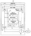
図4は本実施例の通信装置100の機能ブロック構成例の詳細を示す。通信装置100は、標準TCP機能231、独自TCP機能232、プロキシ機能233、NIF250、NIF260を含む。
FIG. 4 shows details of a functional block configuration example of the
プロキシ機能233は、標準TCP機能231のバッファ301、302と独自TCP機能232のバッファ311、312と間で、データを転送する。プロキシ機能233は、通信装置100を通過するTCP通信において、標準TCP機能231と独自TCP機能232とを用いる。
The
具体的には、プロキシ機能233は、LAN110とNIF250との通信において標準TCP機能231を用いる。WAN120とNIF260との間の通信において独自TCP機能232を用いる。これにより、LAN110上で標準TCPによって帯域が制御されているTCP通信を、WAN120では独自TCPによって帯域が制御されるように、帯域制御モードを変換する。
Specifically, the
標準TCP機能231は、受信バッファ301、送信バッファ302、受信部303、送信部304、標準TCP送信帯域制御部305を含む。受信バッファ301は、受信部303が受信したデータの順序の整合性等を確認しプロキシ機能233へ渡す。送信バッファ302は、プロキシ機能233から送信されるデータを一時的にバッファリングするとともにパケット廃棄が起こったときに再送するために保持し、必要なデータを送信部304へ渡す。
The
受信部303は、LAN110からNIF250に届いたデータを受信する。送信部304は、標準TCP送信帯域制御部305に従ってNIF250よりLAN110にデータを送信する。標準TCP送信帯域制御部305は、IETF RFC793に記載のアルゴリズムによって送信部304がデータを送信する帯域を制御する。
The receiving
独自TCP機能232は、受信バッファ311、送信バッファ312、受信部313、送信部314、独自TCP制御部315を含む。受信バッファ311は、受信部313が受信したデータの順序等の整合性を確認しプロキシ機能233へ渡す。送信バッファ312は、プロキシ機能233から送信されるデータを一時的にバッファリングするとともにパケット廃棄が起こったときに再送するために保持し、必要なデータを送信部314へ渡す。
The
受信部313は、WAN120からNIF260に届いたデータを受信する。送信部314は、独自TCP制御部315に従ってNIF260よりWAN120にデータを送信する。独自TCP制御部315は、送信部314がデータを送信する帯域を制御する。
The receiving
独自TCP制御部315は、独自TCP送信帯域制御部321、廃棄率計算部322、送信帯域抑制制御部323、状態テーブル324を含む。状態テーブル324は、独自TCP機能を実行するのに必要な値を格納する。独自TCP送信帯域制御部321は、受信部313から受け取ったデータ及び廃棄率計算部322から受け取った廃棄率をもとに、送信部314がデータを送信する速度を計算する。
The unique
廃棄率計算部322は、受信部313から受け取ったデータをもとに送信部314から送信されたパケットの廃棄率を計算する。送信帯域抑制制御部323は、受信部313から受け取ったデータ及び廃棄率計算部322から受け取った廃棄率をもとに、送信部314から送信されるデータの帯域を制御する。
The discard
送信帯域抑制制御部323の送信帯域抑制機能が有効な場合、当該機能は、inflightが受信部313から受け取ったRWINのδ倍より大きくならないように、帯域を制御する。inflightは、送信部314から送信されるデータのうち受信部313からACKパケットを受け取っていないデータのサイズである。δの値については後述する。
When the transmission band suppression function of the transmission band
図5は本実施例の通信装置100に含まれる独自TCP制御部315の動作概要を示すフローチャートである。通信装置100は、送信帯域抑制機能を有効にすることで受信計算機のバッファ溢れを防ぐ。さらに、送信帯域抑制機能を無効にすることで、受信計算機が通知するRWINに送信帯域が制限されることを防ぐ。
FIG. 5 is a flowchart showing an outline of the operation of the unique
通信装置100は、通信中に送信帯域抑制機能の有効/無効を切り替えることでデータ送信を高速化する。送信帯域抑制機能を無効にしなくてもRWINに送信帯域が制限されない場合は、受信計算機のバッファ溢れを防ぐことによって通信帯域の低下を抑えるため、送信帯域抑制機能を有効にする。
The
受信計算機のバッファが溢れておらず、送信帯域がRWINによって制限されているときは、さらに送信帯域を広げるために送信帯域抑制機能を無効にする。この切替えを動的に行うことによって、受信計算機及びネットワークの状況に応じたデータ通信の高速化を実現する。 When the buffer of the reception computer is not overflowed and the transmission band is limited by RWIN, the transmission band suppression function is disabled to further expand the transmission band. By performing this switching dynamically, high-speed data communication according to the status of the receiving computer and the network is realized.
図5を参照して、通信装置100の動作の概要を説明する。詳細については後述する。通信装置100の起動時(S100)、独自TCP制御部315は、送信帯域抑制機能を有効化した状態で開始する(S101)。受信計算機のオペレーティングシステムはRWINを動的に変化させることがあるため、送信帯域抑制機能を無効にしなくても、RWINが拡大することで送信帯域を拡大する可能性があるからである。送信帯域抑制機能を維持することで、受信計算機のバッファ溢れをより確実に防げる。
With reference to FIG. 5, an outline of the operation of the
独自TCP制御部315は、送信帯域がRWINで制限されているかどうか判定し続ける。RWINが送信帯域を制限していると判定すると(S102)、独自TCP制御部315は、送信帯域抑制機能を無効化することで、送信帯域をRWINに制限されないようにする(S103)。
The unique
送信帯域抑制機能の無効化(S103)後、独自TCP制御部315は、送信帯域抑制機能の無効化が適切かどうか判定し続ける(S104)。ステップS104で送信帯域抑制機能を無効にすることが不適切だと判定する条件は次の通りである。
After invalidating the transmission band suppression function (S103), the unique
(1)独自TCP制御部315は、送信帯域抑制機能を無効にしているときにネットワークの輻輳を検出した場合、送信帯域抑制機能を無効にすることは不適切だと判定する。これにより、RWINに送信帯域を制限されている他の標準TCP通信との通信帯域の公平性を保つ。
(1) The unique
(2)独自TCP制御部315は、受信計算機のバッファ溢れを検出した場合、送信帯域抑制機能を無効にすることは不適切だと判定する。送信帯域抑制機能を有効にすることで、受信計算機のバッファ溢れを防ぐことができる。
(2) When the unique
(3)独自TCP制御部315は、送信帯域抑制機能を有効にしても無効にしても長い時間でみた送信帯域が大きく変わらない場合、送信帯域抑制機能は有効にすることが適切であり、無効にすることは不適切だと判定する。送信帯域抑制機能を有効とすることで、受信計算機のバッファ溢れを未然に防ぐことができる。
(3) The original
以上の判定基準により送信帯域抑制機能の無効化が不適切だと判定された場合(S104:No)、独自TCP制御部315は、送信帯域抑制機能を有効化する(S101)。送信帯域抑制機能を無効化することが不適切であると判定する条件として3つの条件をあげたが、独自TCP制御部315は、全ての条件をそれぞれ用いてもよいし、一部の条件のみを用いてもよい。また、他の条件を使用してもよい。
When it is determined that the invalidation of the transmission band suppression function is inappropriate according to the above determination criteria (S104: No), the unique
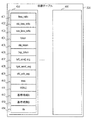
図6は状態テーブル324の例を示す。状態テーブル324は、例えばTCPコネクションごとの状態を記録するためのn個のエントリ400を有する。各エントリ400が含む情報の例は以下の通りである。
FIG. 6 shows an example of the status table 324. The state table 324 has
loss_ratio401は、廃棄率計算部322が計算した最新の廃棄率である。old_loss_ratio402は、廃棄率loss_ratio401が更新される際に廃棄率loss_ratio401の値が格納される旧廃棄率である。ave_loss_ratio403は、廃棄率loss_ratio401のM回分の移動平均値を示す平均廃棄率である。Mの値については後述する。
The
token404は、現在のトークンバケット内のトークンを示す。old_token405は、トークンバケット内のトークンが更新される前のトークンtoken404の値を示す旧トークンである。tmp_token406は、トークンtoken404の値を旧トークンold token405に移すときに一時的に記憶しておく一時トークンである。
token 404 indicates the token in the current token bucket.
left_send_seg407は、送信バッファ312内において、送信済みかつACK受信済みデータへのポインタを示す左端ポインタである。right_send_seg408は、送信バッファ312内において、送信済みかつACKを受信していないデータへのポインタを示す右端ポインタである。old_ack_seg409は、トークンtoken404が更新される直前のACKパケットのACK番号を記憶する旧ACK番号である。mss410は、通信中のTCPセッションにおける最大のペイロードサイズを示す最大セグメントサイズである。
RWND411は、受信部313から受け取った最新のACKパケットに含まれるRWINを示す。基準時刻A412は、次回のトークン更新時刻の基準となる時刻を記憶する。基準時刻は、例えば、トークンバケットの更新時刻である。基準時刻B413は、inflightがRWINのα倍以上となった最近の時刻を記憶する。αの値については後述する。rts414は、再送要求されたパケット数を保存するカウンタである。
図7は、独自TCP送信帯域制御部321の機能ブロック構成例を示す。本実施例における独自TCP送信帯域制御部321は、トークンバケットアルゴリズムを使用する。トークンバケットアルゴリズムは、トークンバケットにトークンを蓄積する。トークンバケット内のトークンが送信パケット長以上である場合、トークンバケットアルゴリズムは、当該パケットを送信する。
FIG. 7 shows a functional block configuration example of the unique TCP transmission
トークンバケットアルゴリズムは、パケットを送信すると、パケット長分のトークンをトークンバケットから減らす。独自TCP送信帯域制御部321は、タイマ501、トークンバケット503、トークンを計算するトークン更新部502を含み、本実施例のトークンバケットアルゴリズムを実現する。独自TCP送信帯域制御部321により、送信帯域抑制機能が無効状態である場合でも、適切に帯域制御を行うことができる。
When a packet is transmitted, the token bucket algorithm reduces tokens for the packet length from the token bucket. The unique TCP transmission
図8は独自TCP送信帯域制御部321の動作例を示すフローチャートである。本実施例のトークンバケットアルゴリズムは、インターバル経過毎に、廃棄率に応じてトークンバケット内のトークンを増減する。これにより廃棄率を低減する。独自TCP送信帯域制御部321は、下記帯域制御と異なるアルゴリズムで送信帯域を制御してもよい。
FIG. 8 is a flowchart showing an operation example of the unique TCP transmission
独自TCP送信帯域制御部321は、処理開始(S200)の後、タイマ501にて、現在時刻を監視する(S201)。具体的には、独自TCP送信帯域制御部321は、現在時刻と基準時刻A412との差が、所定のインターバル以上かどうか判定する。インターバルとして、計測されたRTTを用いてもよい。
The unique TCP transmission
現在時刻と基準時刻A412との差がインターバル以上である場合(S201:Yes)、独自TCP送信帯域制御部321は、廃棄率loss_ratio401に廃棄率計算部322から取得した廃棄率を格納する(S202)。また、独自TCP送信帯域制御部321は、一時トークンtmp_token406に、トークンtoken404の値を退避させる(S203)。
When the difference between the current time and the
次に、独自TCP送信帯域制御部321は、左端ポインタleft_send_seg407の値が変化しているかをチェックする(S204)。その値が変化していない場合(S204:Yes)、独自TCP送信帯域制御部321は、送信バッファ312に未送信データがあるかどうかチェックする(S205)。
Next, the unique TCP transmission
未送信データがない場合(S205:No)、独自TCP送信帯域制御部321は、ステップS201に戻る。未送信データがある場合(S205:Yes)、独自TCP送信帯域制御部321は、トークンtoken404の値を基準時刻A412以降のACK受信量(現在のACK番号−old_ack_seg409)に設定する(S207)。
If there is no untransmitted data (S205: No), the unique TCP transmission
ステップS204において、left_send_seg407の値が進んでいた場合(S204:No)、独自TCP送信帯域制御部321は、旧廃棄率old_loss_ratio402のK倍が廃棄率loss_ratio401以上か判定する(S206)。Kは、所定の定数又は変数である。Kは、1以上又は1未満の値であり、一例において1である。
If the value of
旧廃棄率old_loss_ratio402のK倍が廃棄率loss_ratio401より小さい場合(S206:No)、独自TCP送信帯域制御部321は、トークンtoken404を、旧トークンold token405よりも小さくなるよう、カウンタrts414に基づいて減少させる。例えば、token404を、(old token405−rts414)に変化させる(S208)。
When K times the old discard
旧廃棄率old_loss_ratio402のK倍が廃棄率loss_ratio401以上である場合(S206:Yes)、独自TCP送信帯域制御部321は、token404を所定量だけ増加させる(S209)。増加量は定数又は変数である。
When K times the old discard
ステップS207、S208、S209の後、独自TCP送信帯域制御部321は、廃棄率loss_ratio401を旧廃棄率old_loss_ratio402に、一時トークンtmp_token406を旧トークンold token405に、現在のACK番号を旧ACK番号old_ack_seg409に代入する(S210)。さらに、独自TCP送信帯域制御部321は、基準時刻A412を更新する(S211)。独自TCP送信帯域制御部321は、基準時刻A412を例えば現在時刻に更新する。更新後時刻は、他の時刻でもよい。独自TCP送信帯域制御部321は、更新したtoken404の値に、トークンバケットを更新する(S212)。なお、独自TCP送信帯域制御部321は、上記方法と異なる方法で送信帯域を制御してもよい。
After steps S207, S208, and S209, the unique TCP transmission
図9は廃棄率計算部322の機能ブロック構成例を示す。以下に説明する構成及び方法は廃棄率計算の一例であって、他の構成及び方法により廃棄率を計算してもよい。廃棄率計算部322は、パケットカウント部710、計算部720を含む。パケットカウント部710は、カウンタsnd711、カウンタack.real712、記憶部730を含む。カウンタsnd711は、送信部314より送信されたパケット数をカウントする。カウンタack.real712は、ACK又はSACKされたパケット数をカウントする。記憶部730は、前回のSACKブロックを記憶する。
FIG. 9 shows a functional block configuration example of the discard
記憶部730において、SLE1 731は、SACKオプションフィールドの第一ブロック始端(SACK Left Edge:SLE)を表す。SRE1 735は、終端(SACK Right Edge: SRE)を表す。SLE2 732、SLE3 733、SLE4 734は、それぞれ、第二、第三、第四ブロックの始端を表す。SRE2 736、SRE3 737、SRE4 738は、それぞれ、第二、第三、第四ブロックの終端を表す。
In the
図10は廃棄率計算部322の動作例を示すフローチャートである。処理開始(S300)の後、パケットカウント部710は、ACKパケットを受信(S301)するたびに、ACK番号が進んだかどうかを判定する(S302)。ACK番号が進んでいない場合(S302:No)、パケットカウント部710は、記憶部730からひとつ前に受信したSACKの値(SLE1−4、SRE1−4)を読み出す(S303)。
FIG. 10 is a flowchart illustrating an operation example of the discard
パケットカウント部710は、SACKの値に変化があるか判定する(S304)。具体的には、パケットカウント部710は、SACKブロックのうち終端の番号が小さくなるか、終端の番号が大きくなるか、あるいは2つ以上のブロックが繋がっていないかを判定する。
The
ACK番号又はSACKの値に変化がみられた場合(S302:Yes、S304:Yes)、パケットカウント部710は、変化分のセグメント数を計算して最大セグメントサイズmss410で割り、新規に受信計算機に受信されたパケット数を計算する(S305)。パケットカウント部710は、この値をカウンタack.real712に加算する(S306)。パケットカウント部710は、SACKブロックの値を記憶部730に格納して(S307)、先頭に戻る。計算部720は、廃棄率loss ratio401を、(1−ack.real712/snd711)により算出する。
When there is a change in the ACK number or the SACK value (S302: Yes, S304: Yes), the
図11は送信帯域抑制制御部323の機能ブロック構成例を示す。送信帯域抑制制御部323は、平均廃棄率計算部901、ステートマシン902、送信帯域抑制機能切替部903、送信帯域抑制部904、カウンタcnt905を含む。ステートマシン902及び送信帯域抑制機能切替部903は、切替制御部の一例を構成する。
FIG. 11 shows a functional block configuration example of the transmission band
平均廃棄率計算部901は、廃棄率計算部322がインターバルごとに計算した廃棄率loss_ratio401のM回に渡る移動平均ave_loss_ratio403を計算する。ステートマシン902は、受信部313及び廃棄率計算部322から受けとった情報をもとに動作する。Mは固定値でもよく、可変値でもよい。例えば、平均廃棄率計算部901は、MをRTTと反比例に変化させてもよい。
The average discard
送信帯域抑制機能切替部903は、平均廃棄率計算部901が計算した平均廃棄率ave_loss_ratio403及びステートマシン902の状態をもとに、送信帯域抑制機能の有効とするか無効とするかを判定する。本例において、送信帯域抑制機能の無効/有効は、送信帯域抑制部904をバイパスするか否かにより制御されるが、他の方法を使用してもよい。
The transmission band suppression
送信帯域抑制機能が無効である場合、送信帯域抑制部904は、独自TCP送信帯域制御部321が計算した制御帯域を送信部314に制御帯域として伝達する。独自TCP送信帯域制御部321が計算した制御帯域は、本例におけるトークンバケット503のトークン量に相当する。送信帯域抑制機能が有効である場合、送信帯域抑制部904は、独自TCP送信帯域制御部321が計算した制御帯域と、inflightがRWINのδ倍と等しくなる帯域のうち、小さい方の帯域を送信部314に制御帯域として伝達する。
When the transmission band suppression function is invalid, the transmission band suppression unit 904 transmits the control band calculated by the unique TCP transmission
カウンタcnt905は、ステートマシン902の制御に利用される。δは、例えば、1以下の、固定値又は可変値である。例えば、送信帯域抑制部904は、δを廃棄率loss_ratio401に反比例に変化させてもよい。
The
図12はステートマシン902の状態遷移図である。ステートマシン902は、矢印の始点から終点に遷移し得る。ステートマシン902は、4つの状態をとる。状態1003において、送信帯域抑制機能切替部903は、送信帯域抑制機能を無効にすることが許可されている。
FIG. 12 is a state transition diagram of the
状態1000において、RWINが送信帯域を制限していないと判定されているか、又は送信帯域抑制機能を無効にすることが不適切だと判定されていて、送信帯域抑制機能が有効にされている。状態1001において、RWINが送信帯域を制限していると判定されており、送信帯域抑制機能が有効にされている。状態1002において、RWINが変化しているときに、送信帯域抑制機能が一時的に有効にされている。 In state 1000, it is determined that RWIN does not limit the transmission band, or it is determined that it is inappropriate to disable the transmission band suppression function, and the transmission band suppression function is enabled. In state 1001, it is determined that RWIN limits the transmission band, and the transmission band suppression function is enabled. In the state 1002, when the RWIN is changing, the transmission band suppression function is temporarily enabled.
図13はステートマシン902の動作を示すフローチャートである。これを用いてステートマシン902の状態遷移について説明する。通信装置100の起動(S400)後、ステートマシン902は状態1000から開始する(S401)。
FIG. 13 is a flowchart showing the operation of the
ステートマシン902は、廃棄率計算部322が計算した廃棄率の変化率が閾値以上であるか判定する(S402)。具体的には、ステートマシン902は、廃棄率loss_ratio401が、前回の廃棄率old_loss_ratio402のγ倍以上であるか判定する。
The
廃棄率の変化率が閾値以上である場合(S402:Yes)、ステートマシン902は、ネットワークが輻輳してパケット廃棄が発生したか、受信計算機のバッファが溢れてパケット廃棄が発生したために廃棄率が上昇したと判定する。図5を参照して説明したように、ネットワークの輻輳又はバッファ溢れが検出された場合、送信帯域抑制機能を無効にすることは不適切である(判定条件(1)及び(2))。従って、ステートマシン902は、状態1000に遷移し(S406)、ステップS402に戻る。
When the change rate of the discard rate is equal to or greater than the threshold (S402: Yes), the
廃棄率計算部322が計算した廃棄率loss_ratio401が前回の廃棄率old_loss_ratio402のγ倍よりも小さい場合(S402:No)、ステートマシン902は、RWINが送信帯域を制限しているか判定する(S403)。具体的には、ステートマシン902は、inflightとRWINのα倍とを比較する。
When the discard
inflightがRWINのα倍よりも小さい場合、ステートマシン902は、RWINが送信帯域を制限していないと判定し(S403:No)、カウンタcnt905に1を加える(S404)。カウンタcnt905が閾値N以上である場合(S405:Yes)、ステートマシン902は状態1000に遷移し(S406)、ステップS402に戻る。カウンタcnt905が閾値Nよりも小さい場合(S405:No)、ステートマシン902は、ステップS402に戻る。
When inflight is smaller than α times RWIN, the
inflightがRWINのα倍以上である場合、ステートマシン902は、RWINが送信帯域を制限していると判定し(S403:Yes)、ステートマシン902は、カウンタcnt905に0を代入する(S407)。送信帯域抑制機能が有効になった後、規定条件が満たされた場合に送信帯域抑制機能を無効にするため、αは、0より大きく、δ以下の値である。
When inflight is greater than or equal to α times RWIN, the
現在の状態が状態1003である場合(S408:Yes)、ステートマシン902は、RWINの増減が閾値以上であるか判定する(S409)。具体的には、ステートマシン902は、前回のRWINから現在のRWINへの増加量又は減少量(以下増減量と呼ぶ)が、前回のRWINのZ%以上であるか判定する。
When the current state is the state 1003 (S408: Yes), the
RWINの増減量がZ%以上である場合(S409:Yes)、ステートマシン902は、状態1002に遷移し(S410)、ステップS402に戻る。増減量がZ%未満である場合(S409:No)、ステートマシン902は、ステップS402に戻る。なお、ステートマシン902は、RWINの増加量又は減少量の一方の変化量のみを参照してもよく、増加量と減少量で異なる閾値を使用してもよい。
When the increase / decrease amount of RWIN is equal to or greater than Z% (S409: Yes), the
現在の状態が状態1003でない場合(S408:No)、ステートマシン902は、現在の状態が状態1000か判定する(S411)。現在の状態が状態1000であれば(S411:Yes)、ステートマシン902は、状態1001に遷移し、現在時刻を基準時刻Bに記録し(S412)、1102に戻る。
When the current state is not the state 1003 (S408: No), the
現在の状態が状態1000でない場合(S411:No)、ステートマシン902は、現在の状態が、状態1002であるか判定する(S413)。現在の状態が、状態1002であれば(S413:Yes)、ステートマシン902は、前回のRWINから現在のRWINへの増減量が、前回のRWINのZ%以上であるか判定する(S414)。
When the current state is not the state 1000 (S411: No), the
RWINの増減量がZ%以上である場合(S414:Yes)、ステートマシン902は、ステップS402に戻る。増減量がZ%未満である場合(S414:No)、ステートマシン902は、状態1003に遷移し(S416)、ステップS402に戻る。
When the increase / decrease amount of RWIN is equal to or greater than Z% (S414: Yes), the
現在の状態が状態1002でなければ(S413:No)、ステートマシン902は、基準時刻B413から時間βが経過しているか判定する(S415)。経過していれば(S415:Yes)、ステートマシン902は、状態1003に遷移し(S416)、ステップS402に戻る。経過していなければ(S415:No)、ステートマシン902は、ステップS402に戻る。
If the current state is not the state 1002 (S413: No), the
図5を参照して説明したように、送信帯域抑制機能を有効にしても無効にしても長い時間でみた送信帯域が大きく変わらない場合、送信帯域抑制機能は有効にすることが適切である(条件(3))。RWINによる送信帯域抑制期間が短い場合、送信帯域抑制機能を有効とすることで、受信計算機のバッファ溢れを未然に防ぐことが有効である。基準時刻B413から時間βが経過していることが状態1003に遷移することの条件に含まれることで、RWINによる送信帯域抑制期間が短い場合に、送信帯域抑制機能が無効になることを避ける。 As described with reference to FIG. 5, it is appropriate to enable the transmission band suppression function when the transmission band in the long time does not change greatly even if the transmission band suppression function is enabled or disabled ( Condition (3)). When the transmission band suppression period by RWIN is short, it is effective to prevent the buffer overflow of the reception computer by enabling the transmission band suppression function. The fact that the time β has elapsed from the reference time B413 is included in the condition for transition to the state 1003, thereby avoiding invalidating the transmission band suppression function when the transmission band suppression period by RWIN is short.
上記α、β、γ、N、Zは固定値でもよいし、変化してもよい。例えば、これらの値は、RTTや廃棄率に応じて変化してもよい。 Α, β, γ, N, and Z may be fixed values or may vary. For example, these values may change according to the RTT and the discard rate.
ステートマシン902は、RWINの変化についての判定(S409、S414)を、受信計算機のオペレーティングシステムがRWINを変更中か否か判定するために行う。RWINが増加している場合、受信計算機のバッファサイズが拡大中の可能性がある。その場合、送信帯域がRWINに制限されなくなる可能性があるため、送信帯域抑制機能切替部903は、RWINが一定になるまで送信帯域抑制機能を一時的に有効にする。また、RWINが減少している場合、バッファ溢れの可能性が増加するため、送信帯域抑制機能を一時的に有効にする。
The
ステートマシン902は、基準時刻B413から時間βが経過しているかの判定(S415)を、RWINが継続的に送信帯域を制限している状態であるか、一時的にinflightがRWINのα倍を超えた状態であるかを判定するために行う。基準時刻B413から時間βが経過した場合、ステートマシン902は、RWINが送信帯域を制限している状態であると判定する。一時的な状態による誤判定の可能性を低減する。
The
ステップS405においてカウンタcnt905が閾値Nよりも大きい場合に、ステートマシン902は、状態1000に遷移する(S406)。これは、inflightが一時的にRWINのα倍よりも下回った場合に状態1000に遷移せず、継続的に下回った場合に状態1000に遷移するためである。一時的な状態による誤判定の可能性を低減する。
When the counter cnt905 is larger than the threshold value N in step S405, the
図14は、送信帯域抑制機能切替部903の動作例を示すフローチャートである。処理開始後(S500)、送信帯域抑制機能切替部903は、ステートマシン902が状態1003かどうか判定する(S501)。ステートマシン902が状態1003でない場合(S501:No)、送信帯域抑制機能切替部903は、送信帯域抑制機能を有効にする(S504)。その後、送信帯域抑制機能切替部903は、ステートマシン902の状態を判定するステップS501に戻る。
FIG. 14 is a flowchart illustrating an operation example of the transmission band suppression
ステートマシン902が状態1003である場合(S501:Yes)、ave_loss_ratio403がx%以上であれば(S502:Yes)、送信帯域抑制機能切替部903は、送信帯域抑制機能を有効にする(1204)。その後、送信帯域抑制機能切替部903は、ステートマシン902の状態を判定するステップS501に戻る。
When the
ave_loss_ratio403がx%未満であれば(S502:No)、送信帯域抑制機能切替部903は、送信帯域抑制機能を無効にする(S503)。xは固定の値でもよいし、RTTや廃棄率に応じて動的に変化してもよい。
If the
図13及び図14に示す送信帯域抑制機能の制御において、いくつかのステップを省略してもよい。例えば、廃棄率の変化率、RWINDの変化量、基準時刻Bからの経過時間、平均廃棄率等についての判定を省略してもよい。 Some steps may be omitted in the control of the transmission band suppression function shown in FIGS. 13 and 14. For example, the determination of the change rate of the discard rate, the change amount of RWIND, the elapsed time from the reference time B, the average discard rate, and the like may be omitted.
図15は送信帯域抑制機能有効時及び送信帯域抑制機能無効時における通信シーケンスの比較図である。ここでは、受信計算機620は、常に送信計算機600にRWIN=4380を通知し、また送信計算機600は、常にペイロードサイズが1460のパケットを送信する場合を例として説明する。
FIG. 15 is a comparison diagram of communication sequences when the transmission band suppression function is valid and when the transmission band suppression function is invalid. Here, a case will be described as an example where the
送信帯域抑制機能有効時において、送信計算機600は、ACKを受信する前にパケットを3つまで送信することができる(パケット601〜603)。受信計算機620は3つのパケット601〜603を受信後、対応するACKパケット621〜623を送信計算機600へ返す。送信計算機600はACKパケット621〜623を受信後、再び送信を開始する(604〜606)。このように、送信計算機600は、送信帯域抑制機能有効時、RTT中に最大でRWINまでしかデータを送信することができない。
When the transmission band suppression function is valid, the
送信帯域抑制機能無効時において、送信計算機600は、パケット641〜643を送信し、inflightがRWINに到達してもさらにパケットを送信することができる(パケット644〜647)。その結果、送信計算機600は、RTT中にRWIN以上のデータを送信することができる。これにより、RWINの大きさに依らず、受信計算機の受信バッファやNICのバッファが受信可能な限り送信帯域を大きくすることができる。
When the transmission bandwidth suppression function is disabled, the
なお、図15は、MSSが1460、受信計算機が送信計算機へ通知するRWINが常に4380である例を示しているが、MSS及びRWINは任意の値でよく、それらの値が通信中に値が変化してもよい。 FIG. 15 shows an example in which the MSS is 1460 and the RWIN notified by the receiving computer to the transmitting computer is always 4380. However, the MSS and RWIN may be arbitrary values, and these values may be changed during communication. It may change.
本実施例によれば、送信帯域を高めることが可能なときに受信ウィンドウサイズを超えて送信し、受信ウィンドウサイズを超えて送信すると送信帯域を落とす可能性があるときに受信ウィンドウサイズを超えずに送信することができ、スループットを高めることができる。なお、上記例は、TCP通信における送信帯域制御の例であるが、本発明の送信帯域制御を他の通信プロトコルに適用することができる。 According to the present embodiment, when the transmission bandwidth can be increased, transmission is performed exceeding the reception window size, and when transmission is performed exceeding the reception window size, the transmission window may be reduced without exceeding the reception window size. To increase the throughput. Although the above example is an example of transmission band control in TCP communication, the transmission band control of the present invention can be applied to other communication protocols.
実施例1は、独自TCP機能がプロキシ装置として実装される例を示した。本実施例は、独自TCP機能がオペレーティングシステムのTCP機能として送信計算機に組み込まれる例を説明する。特に断りのない限り、実施例1と同様の構成のものには同じ符号を付し、説明を省略する。 In the first embodiment, the unique TCP function is implemented as a proxy device. In this embodiment, an example in which a unique TCP function is incorporated in a transmission computer as a TCP function of an operating system will be described. Unless otherwise specified, the same components as those in the first embodiment are denoted by the same reference numerals, and description thereof is omitted.
図16は、実施例2における送信計算機800を含むネットワークシステムの構成例を示す。送信計算機800は、LAN110に接続される。実施例1との違いは、経路上に標準TCPと独自TCPの機能を有する通信装置100を設置するのではなく、送信計算機800が独自TCPによって、計算機112、131、132、133、141へデータの送信を開始する点である。
FIG. 16 shows a configuration example of a network system including the
図17は、実施例2における送信計算機800のハードウェア構成図の例を示す。図18は、実施例2における送信計算機800の機能ブロック構成例を示す。アプリケーション801は、独自TCP機能232とデータの受渡しを行い、独自TCP機能232がNIF260を通してLAN110とデータのやり取りを行う。
FIG. 17 illustrates an example of a hardware configuration diagram of the
ここでは、独自TCP機能が送信計算機のオペレーティングシステムに組み込まれる例を挙げたが、ユーザランドのアプリケーションとして独自TCP機能を実装し、同じ又は他のアプリケーションから独自TCP機能を利用する形で、送信計算機に独自TCP機能を組み込んでもよい。 In this example, the unique TCP function is incorporated into the operating system of the transmission computer. However, the unique TCP function is implemented as a userland application, and the unique TCP function is used from the same or another application. May incorporate a unique TCP function.
本実施例は、独自TCP機能が組み込まれるプロキシ装置が仮想通信装置として実装される例を示す。特に断りのない限り、実施例1と同様の構成のものには同じ符号を付し、説明を省略する。 This embodiment shows an example in which a proxy device in which a unique TCP function is incorporated is implemented as a virtual communication device. Unless otherwise specified, the same components as those in the first embodiment are denoted by the same reference numerals, and description thereof is omitted.
図19は、実施例3における仮想通信装置810〜813を含むネットワークシステムの構成図を示す。仮想化基盤830は、サーバ850〜852がソフトウェアリソース(仮想計算機、仮想ネットワーク等)を共有する形で稼働する。仮想通信装置810〜813、仮想計算機831〜833、及び仮想ネットワーク805は、仮想化基盤830上で稼働する。サーバ850〜852を含め、以下の説明において仮想との明示がない構成要素は、実構成要素である。
FIG. 19 is a configuration diagram of a network system including
サーバ850〜852は、LAN110に接続される。仮想計算機831〜833及び仮想通信装置810〜813は仮想ネットワーク805に接続される。仮想通信装置810〜813は、直接又は仮想ネットワーク805を経由してLAN110にも接続される。仮想ネットワーク805は、接続される計算機や通信装置を1つのネットワークとして接続してもよいし、VLAN等の機能を用いて、論理的に複数のネットワークとし、接続される計算機や通信装置を区切ってもよい。
ここで、仮想通信装置810は標準TCP通信を独自TCP通信へ変換するプロキシ装置である。仮想通信装置811〜813は、仮想通信装置810と同一の機能を持つプロキシ装置でもよいし、ファイヤウォールやロードバランサなどの他の機能を持つ通信装置でもよい。
Here, the
例えば仮想計算機831が計算機131へとTCP通信によってデータを送信するとき、仮想計算機831から送信するデータは、標準TCPによって帯域制御されて仮想ネットワーク805を経由して仮想通信装置810に届き、仮想通信装置810からは独自TCPによって帯域制御されて計算機131へと送信される。
For example, when the
図19においては3台のサーバ850〜852が仮想化基盤830のソフトウェアリソースを共有している場合を例として図示しているが、任意の台数のサーバで仮想化基盤830を共有してもよいし、1台のサーバで仮想化基盤830を稼働させてもよい。
In FIG. 19, the case where three
図20は実施例3における仮想通信装置810を含むサーバ850のハードウェア構成図の例を示す。主記憶230は、仮想化基盤機能861、仮想計算機機能862〜864、仮想通信装置機能865〜868、及び仮想ネットワーク機能869を実現するプログラムを格納している。処理装置220がこれらプログラムに従って動作することで、仮想化基盤830、仮想計算機833、仮想ネットワーク805、及び仮想通信装置810が実現される。他のサーバ851、852も同様の構成を有していてよい。
FIG. 20 illustrates an example of a hardware configuration diagram of the
図21はサーバ850の機能ブロック図の例である。仮想通信装置810と実施例1の通信装置100の違いは、NIFとして仮想NIF871及び仮想NIF872の仮想NIFを備える点、仮想NIF871が仮想ネットワーク機能869に接続される点である。仮想NIF871、872は、仮想通信装置機能865内のプログラムモジュールである。
FIG. 21 is an example of a functional block diagram of the
図21は、仮想NIF871が仮想ネットワーク機能869に接続される例を示す、仮想NIF871は、仮想計算機機能862〜864に直接接続されてもよい。図21は、仮想NIF872がNIF260と直接接続される例を示すが、仮想ネットワーク機能869を経由して接続してもよい。
FIG. 21 shows an example in which the
なお、本発明は上記した実施例に限定されるものではなく、様々な変形例が含まれる。例えば、上記した実施例は本発明を分かりやすく説明するために詳細に説明したものであり、必ずしも説明したすべての構成を備えるものに限定されるものではない。また、ある実施例の構成の一部を他の実施例の構成に置き換えることが可能であり、また、ある実施例の構成に他の実施例の構成を加えることも可能である。また、各実施例の構成の一部について、他の構成の追加・削除・置換をすることが可能である。 また、上記の各構成・機能・処理部等は、それらの一部又は全部を、例えば集積回路で設計する等によりハードウェアで実現してもよい。また、上記の各構成、機能等は、プロセッサがそれぞれの機能を実現するプログラムを解釈し、実行することによりソフトウェアで実現してもよい。各機能を実現するプログラム、テーブル、ファイル等の情報は、メモリや、ハードディスク、SSD(Solid State Drive)等の記録装置、または、ICカード、SDカード等の記録媒体に置くことができる。 In addition, this invention is not limited to an above-described Example, Various modifications are included. For example, the above-described embodiments have been described in detail for easy understanding of the present invention, and are not necessarily limited to those having all the configurations described. Further, a part of the configuration of one embodiment can be replaced with the configuration of another embodiment, and the configuration of another embodiment can be added to the configuration of one embodiment. Further, it is possible to add, delete, and replace other configurations for a part of the configuration of each embodiment. Each of the above-described configurations, functions, processing units, and the like may be realized by hardware by designing a part or all of them, for example, with an integrated circuit. Each of the above-described configurations, functions, and the like may be realized by software by interpreting and executing a program that realizes each function by the processor. Information such as programs, tables, and files for realizing each function can be stored in a memory, a hard disk, a recording device such as an SSD (Solid State Drive), or a recording medium such as an IC card or an SD card.
100 通信装置
313 受信部
314 送信部
321 独自TCP送信帯域制御部
322 廃棄率計算部
323 送信帯域抑制制御部
903 送信帯域抑制機能切替部
904 送信帯域抑制部
100
Claims (14)
前記ネットワークを介して受信装置にデータを送信する送信部と、
前記受信装置から前記ネットワークを介して受信確認及び受信ウィンドウサイズの情報を含む確認応答データを受信する受信部と、
前記送信部から送信されるデータに関する帯域を制御する送信帯域制御部と、
前記送信部から送信済みのデータのうち前記受信装置から確認応答を受信していないデータのデータサイズが、前記受信ウィンドウサイズから決まる上限値以下になるように、前記送信帯域制御部により制御されている帯域を抑制する、送信帯域抑制部と、
前記データサイズが前記受信ウィンドウサイズより小さいときに前記送信帯域抑制部を有効とし、前記データサイズが前記受信ウィンドウサイズ以上のときに前記送信帯域抑制部を無効とする、切替制御部と、を含み、
前記切替制御部は、前記送信帯域抑制部を無効とした後、パケット廃棄率の変化率が閾値以上である場合、前記送信帯域抑制部を有効とする、送信装置。 A transmission device connected to a network,
A transmission unit for transmitting data to the reception device via the network;
A receiving unit for receiving acknowledgment data including information on reception confirmation and reception window size from the receiving device via the network;
A transmission band control unit that controls a band related to data transmitted from the transmission unit;
Controlled by the transmission bandwidth control unit so that the data size of the data that has not been received from the receiving device among the data that has already been transmitted from the transmission unit is less than or equal to the upper limit value determined by the reception window size. A transmission band suppression unit that suppresses a band that is
A switching control unit that enables the transmission band suppression unit when the data size is smaller than the reception window size, and disables the transmission band suppression unit when the data size is equal to or larger than the reception window size. See
The switching apparatus, wherein the switching control unit validates the transmission band suppression unit when the rate of change of the packet discard rate is equal to or greater than a threshold value after invalidating the transmission band suppression unit .
前記切替制御部は、前記データサイズが、前記上限値以下の閾値以上であるか否かに基づいて、前記送信帯域抑制部を有効から無効に切り替えるか否か判定する、送信装置。 The transmission device according to claim 1,
The transmission device, wherein the switching control unit determines whether to switch the transmission band suppression unit from valid to invalid based on whether the data size is equal to or larger than a threshold value equal to or less than the upper limit value.
前記切替制御部は、前記データサイズが前記閾値以上である状態が所定時間継続しているか否かに基づいて、前記送信帯域抑制部を有効から無効に切り替えるか否か判定する、送信装置。 The transmission device according to claim 2,
The transmission device, wherein the switching control unit determines whether to switch the transmission band suppression unit from valid to invalid based on whether or not the state where the data size is equal to or larger than the threshold value continues for a predetermined time.
前記切替制御部は、前記受信ウィンドウサイズの変化が閾値より小さいか否かに基づいて、前記送信帯域抑制部を有効から無効に切り替えるか否か判定する、送信装置。 The transmission device according to claim 1,
The transmission device, wherein the switching control unit determines whether to switch the transmission band suppression unit from valid to invalid based on whether or not the change in the reception window size is smaller than a threshold value.
前記切替制御部は、前記送信部から送信されたデータの廃棄率の変化が閾値より小さいか否かに基づいて、前記送信帯域抑制部を有効から無効に切り替えるか否か判定する、送信装置。 The transmission device according to claim 1,
The transmission apparatus, wherein the switching control unit determines whether to switch the transmission band suppression unit from valid to invalid based on whether or not a change in a discard rate of data transmitted from the transmission unit is smaller than a threshold value.
前記切替制御部は、前記送信部から送信されたデータの平均廃棄率が閾値より小さいか否かに基づいて、前記送信帯域抑制部を有効から無効に切り替えるか否か判定する、送信装置。 The transmission device according to claim 1,
The transmission device, wherein the switching control unit determines whether to switch the transmission band suppression unit from valid to invalid based on whether an average discard rate of data transmitted from the transmission unit is smaller than a threshold value.
前記切替制御部は、前記データサイズが前記閾値より小さいか否かに基づいて、前記送信帯域抑制部を無効から有効に切り替えるか否か判定する、送信装置。 The transmission device according to claim 2,
The transmission device, wherein the switching control unit determines whether to switch the transmission band suppression unit from invalid to valid based on whether the data size is smaller than the threshold value.
前記切替制御部は、前記データサイズが前記閾値より小さい状態が所定時間継続している場合に、前記送信帯域抑制部を無効から有効に切り替えるか否か判定する、送信装置。 The transmission device according to claim 7, wherein
The transmission control unit determines whether or not to switch the transmission band suppression unit from invalid to valid when the state where the data size is smaller than the threshold value continues for a predetermined time.
前記切替制御部は、前記受信ウィンドウサイズの変化が閾値以上である場合に、前記送信帯域抑制部を無効から有効に切り替える、送信装置。 The transmission device according to claim 1,
The transmission control device, wherein the switching control unit switches the transmission band suppression unit from invalid to valid when a change in the reception window size is equal to or greater than a threshold value.
前記切替制御部は、前記送信部から送信されたデータの廃棄率の変化が閾値以上である場合に、前記送信帯域抑制部を無効から有効に切り替える、送信装置。 The transmission device according to claim 1,
The transmission control unit, wherein the switching control unit switches the transmission band suppression unit from invalid to valid when a change in the discard rate of the data transmitted from the transmission unit is equal to or greater than a threshold value.
前記切替制御部は、前記送信部から送信されたデータの平均廃棄率が閾値以上である場合に、前記送信帯域抑制部を無効から有効に切り替える、送信装置。 The transmission device according to claim 1,
The transmission device, wherein the switching control unit switches the transmission band suppression unit from invalid to valid when an average discard rate of data transmitted from the transmission unit is greater than or equal to a threshold value.
前記送信帯域制御部は、前記送信部から送信されたデータの廃棄率から決定されるトークンに応じて前記帯域を制御する、送信装置。 The transmission device according to claim 1,
The transmission band control unit controls the band according to a token determined from a discard rate of data transmitted from the transmission unit.
前記ネットワークを介して受信装置にデータを送信し、
前記受信装置から前記ネットワークを介して受信確認及び受信ウィンドウサイズの情報を含む確認応答データを受信し、
前記送信装置から送信されるデータに関する帯域を制御し、
前記送信されるデータのうち前記受信装置から確認応答を受信していないデータのデータサイズが、前記受信ウィンドウサイズから決まる上限値以下になるように、前記制御されている帯域を抑制し、
前記データサイズが前記受信ウィンドウサイズより小さいときに前記帯域の抑制を有に、前記データサイズが前記受信ウィンドウサイズ以上のときに前記帯域の抑制を無に切り替え、
前記帯域の抑制を無に切り替えた後、パケット廃棄率の変化率が閾値以上である場合、前記帯域の抑制を有に切り替える、送信装置の制御方法。 A method of controlling a transmission device connected to a network,
Sending data to the receiving device via the network,
Receiving acknowledgment data including information of reception confirmation and reception window size from the receiving device via the network;
Controlling the bandwidth related to the data transmitted from the transmission device;
Suppressing the controlled bandwidth so that the data size of data that has not received an acknowledgment from the receiving device among the transmitted data is less than or equal to the upper limit value determined from the reception window size,
When the data size is smaller than the reception window size, the band suppression is enabled, and when the data size is equal to or larger than the reception window size, the band suppression is switched to no .
After switching the inhibition of the band-free, when the packet loss ratio of the rate of change is equal to or greater than the threshold, Ru switch to have the suppression of the band, the control method of the transmitting device.
前記インタフェースから受信装置にデータを送信し、
前記インタフェースを介して、前記受信装置から受信確認及び受信ウィンドウサイズの情報を含む確認応答データを受信し、
前記インタフェースから送信されるデータに関する帯域を制御し、
前記送信されるデータのうち前記受信装置から確認応答を受信していないデータのデータサイズが、前記受信ウィンドウサイズから決まる上限値以下になるように、前記制御されている帯域を抑制し、
前記データサイズが前記受信ウィンドウサイズより小さいときに前記帯域の抑制を有に、前記データサイズが前記受信ウィンドウサイズ以上のときに前記帯域の抑制を無に切り替え、
前記帯域の抑制を無に切り替えた後、パケット廃棄率の変化率が閾値以上である場合、前記帯域の抑制を有に切り替える、処理を前記処理装置に実行させる、プログラム。 In a transmission device including an interface, a processing device, and a main memory, a program for causing the processing device to execute control processing of the transmission device,
Sending data from the interface to the receiving device;
Via the interface, receiving confirmation response data including information on reception confirmation and reception window size from the receiving device;
Control bandwidth for data transmitted from the interface;
Suppressing the controlled bandwidth so that the data size of data that has not received an acknowledgment from the receiving device among the transmitted data is less than or equal to the upper limit value determined from the reception window size,
When the data size is smaller than the reception window size, the band suppression is enabled, and when the data size is equal to or larger than the reception window size, the band suppression is switched to no .
After switching the inhibition of the band-free, when the packet loss ratio of the rate of change is equal to or greater than the threshold, Ru switch to have the suppression of the band, to perform the processing to the processing device, a program.
Priority Applications (3)
| Application Number | Priority Date | Filing Date | Title |
|---|---|---|---|
| JP2014005330A JP6234236B2 (en) | 2014-01-15 | 2014-01-15 | Communication device |
| US15/106,183 US9882820B2 (en) | 2014-01-15 | 2014-12-10 | Communication apparatus |
| PCT/JP2014/082690 WO2015107806A1 (en) | 2014-01-15 | 2014-12-10 | Communication apparatus |
Applications Claiming Priority (1)
| Application Number | Priority Date | Filing Date | Title |
|---|---|---|---|
| JP2014005330A JP6234236B2 (en) | 2014-01-15 | 2014-01-15 | Communication device |
Publications (3)
| Publication Number | Publication Date |
|---|---|
| JP2015133669A JP2015133669A (en) | 2015-07-23 |
| JP2015133669A5 JP2015133669A5 (en) | 2016-11-10 |
| JP6234236B2 true JP6234236B2 (en) | 2017-11-22 |
Family
ID=53542710
Family Applications (1)
| Application Number | Title | Priority Date | Filing Date |
|---|---|---|---|
| JP2014005330A Active JP6234236B2 (en) | 2014-01-15 | 2014-01-15 | Communication device |
Country Status (3)
| Country | Link |
|---|---|
| US (1) | US9882820B2 (en) |
| JP (1) | JP6234236B2 (en) |
| WO (1) | WO2015107806A1 (en) |
Families Citing this family (3)
| Publication number | Priority date | Publication date | Assignee | Title |
|---|---|---|---|---|
| US10447543B2 (en) * | 2009-06-11 | 2019-10-15 | Talari Networks Incorporated | Adaptive private network (APN) bandwith enhancements |
| US9069727B2 (en) | 2011-08-12 | 2015-06-30 | Talari Networks Incorporated | Adaptive private network with geographically redundant network control nodes |
| DE112017006939T5 (en) * | 2017-01-27 | 2019-10-10 | Mitsubishi Electric Corporation | RELAY AND PACKET TRANSFER PROCESS |
Family Cites Families (10)
| Publication number | Priority date | Publication date | Assignee | Title |
|---|---|---|---|---|
| JPH09247209A (en) * | 1996-03-12 | 1997-09-19 | Chokosoku Network Computer Gijutsu Kenkyusho:Kk | Flow control system of transport layer protocol for resource reservation channel |
| US20070025250A1 (en) | 2003-08-20 | 2007-02-01 | Nec Corporation | Session relay device and relay method |
| US7564792B2 (en) * | 2003-11-05 | 2009-07-21 | Juniper Networks, Inc. | Transparent optimization for transmission control protocol flow control |
| US7760633B2 (en) * | 2005-11-30 | 2010-07-20 | Cisco Technology, Inc. | Transmission control protocol (TCP) congestion control using transmission delay components |
| JP2007243447A (en) * | 2006-03-07 | 2007-09-20 | Nippon Telegr & Teleph Corp <Ntt> | Packet transmission control apparatus |
| US8125904B2 (en) * | 2006-05-30 | 2012-02-28 | Broadcom Corporation | Method and system for adaptive queue and buffer control based on monitoring and active congestion avoidance in a packet network switch |
| TW200816719A (en) * | 2006-08-23 | 2008-04-01 | Matsushita Electric Ind Co Ltd | Communication equipment |
| JP2009224834A (en) | 2008-03-13 | 2009-10-01 | Nec Commun Syst Ltd | Communication apparatus, communication system, window size adjusting method and program |
| JP5625748B2 (en) * | 2010-10-28 | 2014-11-19 | ソニー株式会社 | COMMUNICATION DEVICE, COMMUNICATION SYSTEM, PROGRAM, AND COMMUNICATION METHOD |
| EP2819353A4 (en) | 2012-02-24 | 2015-05-20 | Hitachi Ltd | Communication device |
-
2014
- 2014-01-15 JP JP2014005330A patent/JP6234236B2/en active Active
- 2014-12-10 WO PCT/JP2014/082690 patent/WO2015107806A1/en active Application Filing
- 2014-12-10 US US15/106,183 patent/US9882820B2/en active Active
Also Published As
| Publication number | Publication date |
|---|---|
| US20170041240A1 (en) | 2017-02-09 |
| WO2015107806A1 (en) | 2015-07-23 |
| US9882820B2 (en) | 2018-01-30 |
| JP2015133669A (en) | 2015-07-23 |
Similar Documents
| Publication | Publication Date | Title |
|---|---|---|
| CN108881056B (en) | Congestion control method, network equipment and network interface controller thereof | |
| CN110661723B (en) | Data transmission method, computing device, network device and data transmission system | |
| EP3166267A1 (en) | Method and apparatus for diverting flow | |
| JP5651805B2 (en) | Communication device | |
| WO2014141006A1 (en) | Scalable flow and congestion control in a network | |
| CN109218222B (en) | Method, device and system for realizing speed regulation of sending end | |
| US11258717B2 (en) | Method for sending service packet, network device, and system | |
| EP3525406A1 (en) | Method and apparatus for determining tcp congestion window | |
| JP6234236B2 (en) | Communication device | |
| JP5832335B2 (en) | Communication apparatus and communication system | |
| CN111224888A (en) | Method for sending message and message forwarding equipment | |
| WO2019244966A1 (en) | Communication device, communication method, and program | |
| US20160149817A1 (en) | Analysis device | |
| JP2008118281A (en) | Communication device | |
| CN113595920B (en) | Network congestion control method and device | |
| US20160277943A1 (en) | Network system, control method of network system, communication device, and program | |
| CN115396372B (en) | Data stream rate control method, intelligent network card, cloud device and storage medium | |
| JP6279970B2 (en) | Processor, communication apparatus, communication system, communication method, and computer program | |
| TWI649991B (en) | Data communication device, data communication control method and program | |
| WO2024088353A1 (en) | Method for controlling rates of data streams, and intelligent network card, cloud device and storage medium | |
| JP6568571B2 (en) | Data transfer device, data transfer method, and communication device | |
| WO2023091056A1 (en) | Congestion control monitoring | |
| JP2011254296A (en) | Information processing apparatus and information processing method | |
| WO2014141437A1 (en) | Communication node apparatus, band control method, and computer readable storage medium | |
| JP2015204466A (en) | Data transfer device, data transfer method, and communication device |
Legal Events
| Date | Code | Title | Description |
|---|---|---|---|
| A521 | Written amendment |
Free format text: JAPANESE INTERMEDIATE CODE: A523 Effective date: 20160921 |
|
| A621 | Written request for application examination |
Free format text: JAPANESE INTERMEDIATE CODE: A621 Effective date: 20160921 |
|
| A131 | Notification of reasons for refusal |
Free format text: JAPANESE INTERMEDIATE CODE: A131 Effective date: 20170718 |
|
| A521 | Written amendment |
Free format text: JAPANESE INTERMEDIATE CODE: A523 Effective date: 20170914 |
|
| TRDD | Decision of grant or rejection written | ||
| A01 | Written decision to grant a patent or to grant a registration (utility model) |
Free format text: JAPANESE INTERMEDIATE CODE: A01 Effective date: 20171017 |
|
| A61 | First payment of annual fees (during grant procedure) |
Free format text: JAPANESE INTERMEDIATE CODE: A61 Effective date: 20171024 |
|
| R150 | Certificate of patent or registration of utility model |
Ref document number: 6234236 Country of ref document: JP Free format text: JAPANESE INTERMEDIATE CODE: R150 |