JP6234094B2 - Focus detection apparatus and imaging apparatus - Google Patents
Focus detection apparatus and imaging apparatus Download PDFInfo
- Publication number
- JP6234094B2 JP6234094B2 JP2013147146A JP2013147146A JP6234094B2 JP 6234094 B2 JP6234094 B2 JP 6234094B2 JP 2013147146 A JP2013147146 A JP 2013147146A JP 2013147146 A JP2013147146 A JP 2013147146A JP 6234094 B2 JP6234094 B2 JP 6234094B2
- Authority
- JP
- Japan
- Prior art keywords
- pixel
- calculation
- focus detection
- pixels
- image
- Prior art date
- Legal status (The legal status is an assumption and is not a legal conclusion. Google has not performed a legal analysis and makes no representation as to the accuracy of the status listed.)
- Expired - Fee Related
Links
Images


Description
本発明は、位相差検出方式により被写体のデフォーカス量などを検出する焦点検出を行う焦点検出装置、撮像装置などに関する。 The present invention relates to a focus detection apparatus, an imaging apparatus, and the like that perform focus detection that detects a defocus amount of a subject by a phase difference detection method.
従来、AF(自動焦点調節)機能を提供するカメラの焦点検出装置として、いわゆる位相差検出方式の焦点検出装置が知られている。このような焦点検出装置では、撮影レンズの異なる射出瞳領域を通過した被写体からの光束を、一対の焦点検出センサ上に結像させる。そして、一対の画素信号列を相対的にシフトさせながら相関演算を行い、一対の画素信号列の相対的な位相差を検出し、該位相差に基づいて撮影レンズのデフォーカス量を求めている。 Conventionally, a so-called phase difference detection type focus detection apparatus is known as a focus detection apparatus for a camera that provides an AF (automatic focus adjustment) function. In such a focus detection apparatus, a light beam from a subject that has passed through different exit pupil regions of the photographing lens is imaged on a pair of focus detection sensors. Then, the correlation calculation is performed while relatively shifting the pair of pixel signal sequences, the relative phase difference between the pair of pixel signal sequences is detected, and the defocus amount of the photographing lens is obtained based on the phase difference. .
また、特許文献1には像信号を生成する焦点検出センサの画素中における異常画素を検出し、異常画素を除外した画素による信号波形に対して相関演算を行う焦点検出装置が提案されている。
しかしながら、上述の特許文献1に開示された従来技術では、異常画素が検出された場合、必ず異常画素を取り除いて、その他の画素からの像信号の位相差を検出する演算を行っている。しかし、異常画素からの信号を取り除いて演算を行うと、超高輝度時に発生する飽和などの異常画素が数多く生じた場合、焦点検出の精度が悪化してしまう恐れがある。例えば、被写体の輝度レベルが非常に明るい場合、除外対象画素が増加し、演算画素数が減少してしまう。少ない演算画素数からは、十分なコントラストが得られないため、位相差を検出する際の相関量も減少することになる。したがって、画素に発生するノイズ成分の影響を受けやすく、焦点検出の精度が悪化してしまうことがある。
However, in the conventional technique disclosed in
そこで、本発明の目的は、超高輝度被写体の撮影において飽和などによる異常画素が数多く発生した場合等でも、焦点検出精度の悪化を軽減できる焦点検出装置、これを用いた撮像装置等を提供することである。 Therefore, an object of the present invention is to provide a focus detection device that can reduce deterioration of focus detection accuracy even when a large number of abnormal pixels occur due to saturation or the like in photographing a super-bright subject, an imaging device using the focus detection device, and the like. That is.
上記目的を達成するために、本発明の焦点検出装置は、撮影光学系の一対の瞳領域を通過した光束により形成される一対の被写体の像信号を受光し、出力する複数の画素を含む受光手段と、前記受光手段から出力される像信号で形成される一対の画素信号列に含まれる異常信号を発生する異常画素を検出する異常画素検出手段と、前記異常画素検出手段により検出された異常画素による信号を含んだ一対の画素信号列の位相差を検出する第一演算手段と、異常画素による信号を除外した一対の画素信号列の位相差を検出する第二演算手段と、前記第一演算手段と前記第二演算手段からの結果のいずれか一方を選択する判定手段と、を備え、前記判定手段により選択された結果を基に焦点状態を検出することを特徴とする。 In order to achieve the above object, a focus detection apparatus according to the present invention includes a plurality of pixels that receive and output an image signal of a pair of subjects formed by a light beam that has passed through a pair of pupil regions of a photographing optical system. Means, an abnormal pixel detecting means for detecting an abnormal pixel that generates an abnormal signal included in a pair of pixel signal sequences formed by the image signal output from the light receiving means, and an abnormality detected by the abnormal pixel detecting means A first computing means for detecting a phase difference between a pair of pixel signal sequences including a signal from a pixel; a second computing means for detecting a phase difference between a pair of pixel signal sequences excluding a signal from an abnormal pixel; And a determination unit that selects one of the results from the second calculation unit, and the focus state is detected based on the result selected by the determination unit.
本発明によれば、一対の像信号を受光した時に超高輝度光源などの被写体による異常画素が発生した場合等においても、比較的精度の高い焦点検出を行うことができる。 According to the present invention, it is possible to perform focus detection with relatively high accuracy even when an abnormal pixel is generated by a subject such as an ultra-high brightness light source when a pair of image signals are received.
本発明では、受光手段からの像信号による一対の画素信号列中の異常信号を発生する画素を検出し、異常画素信号を含んだ一対の画素信号列の位相差を検出する第一演算と、異常画素信号を除外した一対の画素信号列の位相差を検出する第二演算を実行する。そして、異常画素が発生した場合においても、比較的精度の高い焦点検出を行うことができるように、第一演算と第二演算の結果のいずれか一方を所定の判定基準に基づいて選択し、選択された結果を基に焦点状態を検出する。 In the present invention, a first calculation for detecting a pixel that generates an abnormal signal in a pair of pixel signal sequences based on an image signal from the light receiving means, and detecting a phase difference between the pair of pixel signal sequences including the abnormal pixel signal; A second operation for detecting a phase difference between a pair of pixel signal sequences excluding abnormal pixel signals is executed. And even when an abnormal pixel occurs, select one of the results of the first calculation and the second calculation based on a predetermined criterion so that relatively accurate focus detection can be performed, The focus state is detected based on the selected result.
以下に、本発明の好ましい実施の形態を、添付の図面に基づいて詳細に説明する。図1は、本発明の実施形態にかかわる焦点検出装置を備えた撮像装置である。
(実施例1)
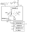
図1において、本実施例における撮像装置は、レンズ交換式の一眼レフカメラ(以下、単に「カメラ」と称する)100である。カメラ100は、カメラ本体30と、カメラ本体30に脱着可能に構成された撮影レンズユニット20とで構成される。撮影レンズユニット20とカメラ本体30は、図中央の縦方向の点線で示したマウントを介して接続される。撮影レンズユニット20は、撮影レンズ21と、絞り22と、レンズ側MPU(マイクロプロセッシングユニット)1と、レンズ駆動ユニット2と、絞り駆動ユニット3と、繰り返し位置検出ユニット4と、光学情報テーブル5とを備える。
Hereinafter, preferred embodiments of the present invention will be described in detail with reference to the accompanying drawings. FIG. 1 is an image pickup apparatus including a focus detection apparatus according to an embodiment of the present invention.
Example 1
In FIG. 1, the imaging apparatus according to the present embodiment is a lens interchangeable single-lens reflex camera (hereinafter simply referred to as “camera”) 100. The
レンズ側MPU1は、撮影レンズユニット20の動作に関する全ての演算及び制御を行う。レンズ駆動ユニット2は、レンズ側MPU1による制御に応じて撮影レンズ21を駆動する駆動部である。絞り駆動ユニット3は、レンズ側MPU1による制御に応じて絞り22を駆動する駆動部である。繰り返し位置検出ユニット4は、レンズ鏡筒の繰り返し位置を検出する検出部である。光学情報テーブル5は、自動焦点調節に必要な光学情報であり、不図示のメモリなどに記憶されている。
The
カメラ本体30は、カメラ側MPU6と、焦点検出ユニット7と、シャッター駆動ユニット8と、ダイヤルユニット10と、測光ユニット11、メモリ23とを備える。また、カメラ本体30は、メインミラー12と、サブミラー13と、ピント板14と、ペンタミラー15と、ファインダー16と、撮像素子(イメージセンサ)101と、スイッチSW1_18とスイッチSW2_19とを備える。カメラ側MPU6は、カメラ本体30の動作に関する全ての演算及び制御を行う。また、カメラ側MPU6は、マウントの信号線を介してレンズ側MPU1に接続され、レンズ側MPU1からレンズ位置情報を取得したり、レンズ駆動及び交換レンズごとに固有の光学情報を取得したりする。
The
また、カメラ側MPU6には、カメラ本体30の動作を制御するためのプログラムが格納されたROM(不図示)、変数を記憶するRAM(不図示)、各種パラメータを記憶するEEPROM(電気的消去、書き込み可能メモリ)(不図示)が内蔵されている。ROMに格納されたプログラムにより、後述の焦点検出処理が実行される。また、17はLCD等の表示器で、カメラの撮影モードに関する情報、撮影前のプレビュー画像と撮影後の確認用画像等を表示する。
The camera-
焦点検出ユニット7は、後述する焦点検出センサを備え、焦点検出処理を行うと共に、位相差検出方式により焦点検出を行う。焦点検出ユニット7は、焦点検出センサからの信号読み出し完了をカメラ側MPU6に通知する。シャッター駆動ユニット8は、不図示シャッターを駆動するための駆動部である。ダイヤルユニット10は、カメラ100の諸設定を変更するための操作部であり、例えば、連続撮影速度(連写速度)やシャッター速度、絞り値、撮影モード等の切り替えなどを行うことができる。測光ユニット11は、測光センサを備え、不図示のレリーズボタンへの半押し操作に応じて、ペンタミラー15からの光束に基づき測光センサ(不図示)を介して測光処理を行う。これらはいずれもカメラ側MPU6に接続されている。測光センサは、フォトダイオード等の光電変換素子及びその信号処理回路等からなり、被写体の輝度レベルに関する信号出力を行い、その出力信号はカメラ側MPU6に入力される。
The
メインミラー12は、撮影レンズユニット20を介して入射された光束のほとんどを上方へ折り返し、ピント板14上に被写体像を結像させる機能を有する。ピント板14上の被写体像はペンタミラー15により正立正像に変換反射されてファインダー16へ導かれる。これにより、光学ファインダーとして機能する。ペンタミラー15を透過した一部の光は、測光ユニット11へ導かれる。また、メインミラー12は、入射された光束の一部を透過させ、透過した光がサブミラー13を介して焦点検出ユニット7へと導かれる。そして、カメラ100が撮影状態になると、メインミラー12及びサブミラー13が退避して、撮影レンズユニット20を介して入射される被写体からの光束がイメージセンサ101に結像される。スイッチSW1_18は、レリーズボタンの第1ストローク操作(半押し)によりONするスイッチである。スイッチSW2_19は、レリーズボタンの第2ストローク操作(全押し)によりONするスイッチである。
The
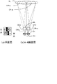
次に、焦点検出ユニット7の構成について図2を用いて説明する。図2は、図1の焦点検出ユニット7の概略構成を示す。撮影レンズユニット20からの入射光の一部は、メインミラー12を透過し、後方のサブミラー13で下方へ曲げられ、焦点検出ユニット7へ導かれる。焦点検出ユニット7は、視野マスク102、赤外線カットフィルタ103、フィールドレンズ104、絞り105、二次結像レンズ106、焦点検出センサ107、複数の反射ミラー108a〜108cで構成される。焦点検出用の焦点検出センサ107は、フォトダイオード等の光電変換素子で構成された一対のラインセンサ及びその信号処理回路等からなる。そして、被写体までの距離或いはデフォーカス量に関する画素信号(像信号)出力を行い、その像信号はカメラ側MPU6に入力される。本明細書では、一対のラインセンサからの像信号をA像、B像とする。カメラ側MPU6は、焦点検出処理に関わるブロックとして、異常画素検出部(異常画素検出手段)111、相関演算部(演算手段)112、演算切替判定部(判定手段)113を有する。
Next, the configuration of the
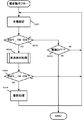
次に、図1のカメラ100における基本動作を、図3のフローチャートを用いて説明する。図1のカメラ100の電源がONされると、メモリ内容や実行プログラムの初期化状態を検出すると共に、撮影準備動作を実行し、図3のフローチャートが開始する。ステップS201では、カメラ側MPU6は、ユーザーが各種ボタン(不図示)を操作してカメラの各種設定を行ったことを認識する。ステップS202では、カメラ側MPU6は、スイッチSW1_18がONされたか否かの判定を行う。スイッチSW1_18がONされた場合はステップS204に移行する。一方、ONされていない場合はステップS203に移行し、電源のON/OFF判定を行う。電源OFFの場合は一連の撮影動作を終了する。電源がONの場合は、ステップS201の動作へ戻る。
Next, the basic operation of the
ステップS204では、カメラ側MPU6は、スイッチSW1_18がONされたことに対応して、後述する焦点検出処理を行う。ステップS205では、カメラ側MPU6は、スイッチSW2_19がONされたか否かの判断を行い、スイッチSW2_19がONされたと判断すればステップS206の撮影処理を行う。一方、カメラ側MPU6は、スイッチSW2_19がONされていないと判断すればステップS201へ戻る。
In step S204, the
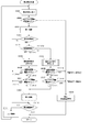
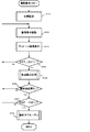
図4は、本実施例における図3のステップS204の焦点検出処理を示すフローチャートである。ステップS301では、カメラ側MPU6は、焦点検出センサに対して、信号蓄積指示を出力する。指示に基づき、焦点検出センサは信号蓄積動作を開始する。そして、蓄積動作が終了すると焦点検出センサは、一対のラインセンサで得た像信号をそれぞれA像、B像としてカメラ側MPU6に出力する。ステップS301で出力したA像、B像の一例を図5に示す。この例では、A像とB像は−2bit〜−3bitの位相差がある。ここでは、A像がB像に対して右に存在する場合を負の位相差と定義する。図5のA像、B像の信号レベルは、共に飽和レベルを超えていない。A像、B像について、仮に飽和レベルを超えている画素が存在している場合、飽和レベルを超えた画素信号は飽和レベルにクリップされて出力される。
FIG. 4 is a flowchart showing the focus detection process in step S204 of FIG. 3 in the present embodiment. In step S301, the camera-
次にステップS302では、カメラ側MPU6は、ステップS301で焦点検出センサから出力された像信号から得たコントラスト情報が所定量以下であるか否かの判定を行う。コントラスト情報が所定量以下の場合は、ステップS303に移行し、焦点検出を行わずに、焦点検出が不可能であることをユーザーに警告する。一方、コントラスト情報が所定量より大きい場合、ステップS304の第一演算に移行する。ここでのコントラスト情報とは、カメラ側MPU6が、像信号の演算画素範囲において、画素信号列の互いに隣接した画素の画素信号の差分を二乗した値の総和である。コントラスト情報が小さい場合、位相差を検出する際、後述する相関量も小さくなる。したがって、画素に発生するノイズ成分の影響を受けやすく焦点検出の精度が悪化する。以上の理由から、コントラスト情報が小さく焦点検出の信頼性が十分ではない場合は、焦点検出を行わない。
Next, in step S302, the camera-
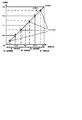
次にステップS304では、カメラ側MPU6は、A像、B像を基に図2の相関演算部112にて第一演算を行う。第一演算について詳細に説明する。第一演算におけるA像、B像のシフト波形と相関量の演算方法について、図6を用いて説明する。焦点検出センサから取得した像信号を所定画素分(bit)シフトさせた波形をシフト波形と定義する。図6(a)はセンサから取得した像信号そのものであり、シフト量0のシフト波形である。図6(b)はシフト量−1bitのシフト波形、図6(c)はシフト量−2bitのシフト波形を示している。ここでは、B像を固定して、A像を左右にシフトすることでシフト量を制御する。下記の相関演算式(1)を用いて、シフト量kbitでの相関量C(k)を演算する。
Next, in step S304, the

この例では、最大シフト量は±4bitとし、9つのシフト波形をRAMに保存する。また、演算範囲は、最大シフト量を考慮し、出力されたA像、B像の総画素数25のうちの最初と最後の4bit分を演算から除外した範囲を演算範囲として設定する。そこで、各シフト波形のA像、B像の差分面積(図6(a)〜(c)の斜線部の面積)を相関量Cとし、シフト波形の相関量Cが最も小さくなるシフト量がA像、B像の位相差に対応する。 In this example, the maximum shift amount is ± 4 bits, and nine shift waveforms are stored in the RAM. The calculation range is set as a calculation range in consideration of the maximum shift amount and a range in which the first 4 bits and the last 4 bits of the total number 25 of the output A and B images are excluded from the calculation. Accordingly, the difference area between the A image and B image of each shift waveform (the area of the shaded portion in FIGS. 6A to 6C) is the correlation amount C, and the shift amount with the smallest correlation amount C of the shift waveform is A. This corresponds to the phase difference between the image and the B image.
このように、図6(a)の2つの画素信号を相対的に±4bitの範囲でシフトさせた時の相関量Cを図7に示す。シフト量k=−2bitの時の相関量が最も小さい値となっているが、極小値は点線で示すようにk=−2bit〜−3bitにある。そこで、シフト量k=−2とその近傍の相関量情報から補間演算することで、位相差検出の分解能を上げる。ここでは、シフト量k=−1bit〜−4bitの4つの相関量Cを用いることで、破線のように直線補間している。直線補間に用いる4つのシフト量は、以下の通り決定する。まず、最も小さい相関量を示すシフト量kを決定し、その近傍をシフト量k−2、k−1、k+1とする。また、相関量が最小なものが2つある場合は、シフト量が大きい方をシフト量kとして採用する。このように、第一演算手段は、一対の画素信号列を相対的に一画素ずつシフトさせ、複数のシフト位置における相関量から補間演算することで、像信号の一対の画素信号列の位相差を一画素より小さい単位で検出可能である。後述の第二演算手段でも、演算原理は同じである。 FIG. 7 shows the correlation amount C when the two pixel signals in FIG. 6A are thus shifted within a relative range of ± 4 bits. Although the correlation amount is the smallest value when the shift amount k = -2 bits, the minimum value is in k = -2 bits to -3 bits as indicated by the dotted line. Therefore, the phase difference detection resolution is increased by performing an interpolation calculation from the shift amount k = −2 and the correlation amount information in the vicinity thereof. Here, linear interpolation is performed as shown by a broken line by using four correlation amounts C of shift amounts k = −1 bit to −4 bits. The four shift amounts used for linear interpolation are determined as follows. First, the shift amount k indicating the smallest correlation amount is determined, and the vicinity thereof is set as shift amounts k−2, k−1, and k + 1. When there are two items having the smallest correlation amount, the larger shift amount is adopted as the shift amount k. In this way, the first calculation means shifts the pair of pixel signal sequences relatively one pixel at a time, and performs an interpolation calculation from the correlation amounts at a plurality of shift positions, whereby the phase difference between the pair of pixel signal sequences of the image signal. Can be detected in units smaller than one pixel. The calculation principle is the same in the second calculation means described later.
次にステップS305では、カメラ側MPU6は、異常信号を検出する手段を備えた図2の異常画素検出部111により、ステップS301で取得した一対の像信号であるA像、B像の画素信号列中における異常画素(飽和画素、欠陥画素)を検出する。ここでは飽和画素を異常画素として検出する。飽和画素が存在しない場合は、ステップS310の合焦判定に移行する。一方、飽和画素が存在する場合はステップS306に移行する。ステップ306では、ステップ304の第一演算の補間演算で使用した4つのシフト波形と、ステップ305で検出した飽和画素の情報から、飽和画素を除外した波形を生成する。ここでは、4つのシフト波形から飽和した画素信号とその近傍の画素信号が除外された波形を生成する。飽和画素を除外した波形の生成方法の詳細は後述する。
Next, in step S305, the camera-
ステップS307〜S308では、図2の演算切替判定部113にて、ステップS304の第一演算の結果と、後述する飽和画素と飽和画素の近傍の画素を除外して演算する第二演算の結果の信頼性判定を行う。信頼性判定は、画素数とコントラストの2つの項目とする。 In steps S307 to S308, the calculation switching determination unit 113 in FIG. 2 calculates the result of the first calculation in step S304 and the result of the second calculation calculated by excluding a saturated pixel and pixels near the saturated pixel, which will be described later. Perform reliability judgment. The reliability determination is made up of two items, the number of pixels and the contrast.
ステップS307では、飽和画素を除外した波形生成の処理を施した4つの除外波形において、演算範囲内の画素数が所定数以下であるか否かの判定を行う。演算画素数が所定数以下である場合は、飽和画素とその近傍の画素を含めて演算する第一演算の方がより精度が高いと判定し、ステップS310の合焦判定に移行する。一方、演算画素数が所定数より多い場合、ステップS308のコントラスト情報による判定へ移行する。 In step S307, it is determined whether or not the number of pixels in the calculation range is equal to or less than a predetermined number in the four excluded waveforms subjected to the waveform generation process excluding the saturated pixels. When the number of calculation pixels is equal to or less than the predetermined number, it is determined that the first calculation including the saturated pixel and the neighboring pixels is more accurate, and the process proceeds to the focus determination in step S310. On the other hand, when the number of operation pixels is larger than the predetermined number, the process proceeds to the determination based on the contrast information in step S308.
ここで、上記ステップS307について図9を用いて詳細に説明する。図9は除外波形生成の処理を施した4つの除外波形のうちの1つを示している。横軸は画素位置、縦軸は像信号のレベルを示している。図9で示している除外範囲は、除外対象画素の位置を示しており、図5に示した波形と比べて、中央部の信号が飽和レベルを超えているものとする。演算画素範囲は4〜8画素目と14〜21画素目となっている。 Here, step S307 will be described in detail with reference to FIG. FIG. 9 shows one of the four excluded waveforms that have been subjected to the processing of generating the excluded waveform. The horizontal axis indicates the pixel position, and the vertical axis indicates the level of the image signal. The exclusion range illustrated in FIG. 9 indicates the position of the pixel to be excluded, and it is assumed that the central signal exceeds the saturation level as compared to the waveform illustrated in FIG. The calculation pixel ranges are the 4th to 8th pixels and the 14th to 21st pixels.
演算画素数が少ない像信号の場合、相関量も小さくなる。そのため、被写体の明暗から得られる画素信号に対してノイズの割合が大きくなり、信頼性が低いと判定できる。したがって、除外対象画素が多くなることで演算画素数が所定数以下になってしまう場合は、第一演算の結果に基づいて焦点検出を行う。第一演算の結果を用いる理由は、次の通りである。まず、ステップS302の判定により、十分なコントラストが得られており、飽和の影響を受けにくい。更に、演算画素数が少ない波形から求める焦点検出の結果より、飽和画素近傍の除外対象になっている正常な画素信号を用いて演算する場合の方が、より精度の高い焦点検出が可能であるためである。 In the case of an image signal with a small number of calculation pixels, the correlation amount is also small. Therefore, the ratio of noise increases with respect to the pixel signal obtained from the brightness of the subject, and it can be determined that the reliability is low. Therefore, when the number of pixels to be excluded becomes less than a predetermined number due to an increase in the number of pixels to be excluded, focus detection is performed based on the result of the first calculation. The reason for using the result of the first calculation is as follows. First, sufficient contrast is obtained by the determination in step S302, and is not easily affected by saturation. Furthermore, more accurate focus detection is possible when the calculation is performed using normal pixel signals to be excluded in the vicinity of the saturated pixel than the result of focus detection obtained from a waveform with a small number of calculation pixels. Because.
次にステップS308では、ステップS306で生成した除外波形のコントラスト情報が所定値以下であるか否かの判定を行う。コントラスト情報が所定値以下である場合は、第一演算がより精度が高いと判定し、ステップS310の合焦判定に移行する。一方、コントラストが所定値より大きい場合は、第二演算が第一演算より精度が高いと判定し、ステップS309の第二演算へ移行する。 Next, in step S308, it is determined whether or not the contrast information of the excluded waveform generated in step S306 is equal to or less than a predetermined value. If the contrast information is less than or equal to the predetermined value, it is determined that the first calculation is more accurate, and the process proceeds to the focus determination in step S310. On the other hand, if the contrast is greater than the predetermined value, it is determined that the second calculation is more accurate than the first calculation, and the process proceeds to the second calculation in step S309.
ここで、上記ステップS308について前述した図9を用いて詳細に説明する。コントラスト情報は演算画素範囲における隣接画素間の差分を二乗した値の総和とし、次の式(2)に示す。CNTは、コントラスト情報のことを示している。 Here, step S308 will be described in detail with reference to FIG. Contrast information is the sum of values obtained by squaring differences between adjacent pixels in the calculation pixel range, and is expressed by the following equation (2). CNT indicates contrast information.
ここで、kはA(i)、A(i+1)のいずれかの画素が除外対象の画素である場合は0とし、A(i)、A(i+1)の画素がともに演算画素範囲の画素である場合は1として、演算画素範囲の画素からコントラスト情報を求める。図9では、9〜13画素目までは除外対象画素であり、この間の画素信号によるコントラスト情報は、式(2)のCNTには加算されない。また、コントラスト情報は、A像、B像それぞれに対して式(2)を用いて求め、A像、B像の小さい方のコントラスト情報をとることとする。式(2)より求めたコントラスト情報と演算切替判定部113に記憶されている所定の判定値との大小関係の比較を4つの除外波形に対して行い、判定を行う。コントラスト情報とAF精度についても、ステップS307の演算画素数と同様の関係にあり、コントラスト情報が小さい像信号から求めた相関量はノイズを受けやすくなる。したがって、除外処理を行った波形から求めたコントラスト情報が所定量以下の場合、第一演算の結果に基づいて焦点検出を行う。 Here, k is 0 when any pixel of A (i) and A (i + 1) is a pixel to be excluded, and both the pixels of A (i) and A (i + 1) are pixels in the calculation pixel range. If there is one, the contrast information is obtained from the pixels in the calculation pixel range. In FIG. 9, the 9th to 13th pixels are pixels to be excluded, and the contrast information based on the pixel signal during this period is not added to the CNT in Expression (2). The contrast information is obtained for each of the A image and the B image using Equation (2), and the contrast information of the smaller one of the A image and the B image is taken. The comparison is performed on the four excluded waveforms by comparing the magnitude relationship between the contrast information obtained from the equation (2) and the predetermined determination value stored in the calculation switching determination unit 113. Contrast information and AF accuracy are also in the same relationship as the number of calculated pixels in step S307, and the correlation amount obtained from an image signal with small contrast information is susceptible to noise. Therefore, when the contrast information obtained from the waveform subjected to the exclusion process is less than or equal to a predetermined amount, focus detection is performed based on the result of the first calculation.
以上のステップS307、ステップS308の2つの信頼性項目について規定の所定値を超えた場合は、飽和画素とその近傍画素を除外した第二演算がより精度が高いと判定し、ステップS309の第二演算に移行する。 If the prescribed value is exceeded for the two reliability items in steps S307 and S308, it is determined that the second calculation excluding the saturated pixel and its neighboring pixels is more accurate, and the second calculation in step S309 is performed. Move on to computation.
次にステップS309では、ステップS306の飽和画素を除外する波形生成で生成した4つのシフト波形から、ステップS304の第一演算と同様に上記式(1)を用いて相関量Cを求める。それぞれの相関量から極小値となるシフト量を求め、第二演算結果とする。相関量C(F−1)とC(F)をつないだ直線と、相関量C(F+1)とC(F+2)をつないだ直線の交点を相関量の極小値とし、位相差を算出する。 Next, in step S309, the correlation amount C is obtained from the four shift waveforms generated by the waveform generation excluding the saturated pixels in step S306 using the above equation (1) in the same manner as the first calculation in step S304. A shift amount that is a minimum value is obtained from each correlation amount, and is used as the second calculation result. The phase difference is calculated by setting the intersection of the straight line connecting the correlation amounts C (F-1) and C (F) and the straight line connecting the correlation amounts C (F + 1) and C (F + 2) as the minimum value of the correlation amount.
ステップS310では、ステップS304もしくはステップS309で算出された位相差が所定の範囲内であるか否かの判定を行う。レンズの駆動量を示すデフォーカス量に変換するため、算出された位相差に係数を乗じてデフォーカス量を求める。求めたデフォーカス量が所望の範囲内、例えば1/4Fδ以内(F:レンズの絞り値、δ:定数:20μm、したがってF2.0のレンズの開放絞りでは10μm)であるならば合焦と判断し、一連の焦点検出処理を終了する。一方、1/4Fδより大であるならば、ステップS311のレンズ駆動に移行する。ステップS311では、ステップS304もしくはS309で算出された位相差の情報に基づき、レンズ駆動量を算出してレンズ側MPU1に送信する。レンズ側MPU1は、送信されたレンズ駆動量を基にレンズ駆動制御を行い、ステップS301に戻り、合焦状態になるまで前述の動作が繰り返される。
In step S310, it is determined whether or not the phase difference calculated in step S304 or step S309 is within a predetermined range. In order to convert to a defocus amount indicating the lens drive amount, the defocus amount is obtained by multiplying the calculated phase difference by a coefficient. If the calculated defocus amount is within a desired range, for example, within 1/4 Fδ (F: lens aperture value, δ: constant: 20 μm, and therefore 10 μm for the open aperture of F2.0 lens), it is determined to be in focus. Then, a series of focus detection processing ends. On the other hand, if it is greater than 1 / 4Fδ, the process proceeds to lens driving in step S311. In step S311, a lens driving amount is calculated based on the phase difference information calculated in step S304 or S309, and is transmitted to the lens side MPU1. The lens-
ここで飽和画素を除外する波形生成方法について、図8のフローチャートを用いて詳細に説明する。ステップS401では、第一演算から検出した位相差Pを基に第二演算で使用するシフト量の範囲を決定する。まず、最初に処理を行うシフト波形のシフト量k=F−1に設定する。Fは、検出した位相差Pよりも小さい整数に丸めた値とする。図7を例にすると、位相差P=−2bit〜−3bitであり、F=−3となる。ステップS402では、第一演算で取得したシフト量(k)のシフト波形をRAMから読み出す。 Here, a waveform generation method for excluding saturated pixels will be described in detail with reference to the flowchart of FIG. In step S401, a shift amount range used in the second calculation is determined based on the phase difference P detected from the first calculation. First, the shift amount k = F−1 of the shift waveform to be processed first is set. F is a value rounded to an integer smaller than the detected phase difference P. Taking FIG. 7 as an example, the phase difference P = −2 bits to −3 bits and F = −3. In step S402, the shift waveform of the shift amount (k) acquired by the first calculation is read from the RAM.
ステップS403で、ステップS402で読み出したシフト波形から1画素ずつA像、B像のいずれかが飽和画素であるか判断し、飽和画素の位置を検知する。画素信号と予めRAMに記憶してある飽和レベルの値とを比較することで飽和の判定を行う。ステップS404では、ステップS403で飽和画素と判定された画素の位置をRAMに記憶する。ステップS405では、kがF+2か否かの判定を行い、F+2であればステップS407へ移行する。つまり、ここでは4つのシフト量のシフト波形について飽和画素の検知処理を行った場合に次のステップS407へ移行する。一方、F+2よりも小さければ、飽和画素を検知すべきシフト波形が残っているので、ステップS406で、シフト量k=k+1を設定し、次のシフト量のシフト波形について検知処理を行う。 In step S403, it is determined whether one of the A image and the B image is a saturated pixel from the shift waveform read in step S402, and the position of the saturated pixel is detected. Saturation is determined by comparing the pixel signal with a saturation level value stored in advance in the RAM. In step S404, the position of the pixel determined as the saturated pixel in step S403 is stored in the RAM. In step S405, it is determined whether or not k is F + 2. If F + 2, the process proceeds to step S407. That is, here, when the saturated pixel detection process is performed for the shift waveforms of the four shift amounts, the process proceeds to the next step S407. On the other hand, if it is smaller than F + 2, the shift waveform for detecting the saturated pixel remains, so in step S406, the shift amount k = k + 1 is set, and the detection processing is performed for the shift waveform of the next shift amount.
ステップS407では、ステップS404で夫々のシフト波形における飽和画素位置が記憶されているため、ステップS404で飽和画素位置として記憶された画素位置をRAMから読み出す。そして、4つのシフト波形のいずれか一か所でも飽和画素位置として記憶された画素位置を除外対象の画素位置とする。 In step S407, since the saturated pixel position in each shift waveform is stored in step S404, the pixel position stored as the saturated pixel position in step S404 is read from the RAM. Then, a pixel position stored as a saturated pixel position at any one of the four shift waveforms is set as a pixel position to be excluded.
ここで上記ステップS407について、図10と図11を用いて詳細に説明する。図10は第二演算で用いる4つのシフト波形を示している。横軸は画素位置、縦軸は像信号のレベルを示している。図10におけるシフト波形は、図4のステップS304の第一演算の結果でRAMに記憶したF−1、F、F+1、F+2のシフト量、ここではF=−3のためシフト量k=−4、−3、−2、−1のシフト波形である。図10(a)はシフト量k=−1のシフト波形であり、画素位置9〜12でA像、B像のいずれかに飽和画素が存在し、カメラ側MPU6は飽和画素位置として画素位置9、10、11、12の4画素をRAMに記憶する。図10(b)はシフト量k=−2のシフト波形であり、図10(a)と同様の判定により画素位置9、10、11の3画素をRAMに記憶する。図10(c)はシフト量k=−3のシフト波形であり、上記と同様の判定により画素位置9、10、11の3画素をRAMに記憶する。図10(d)ではシフト量k=−4のシフト波形であり、上記と同様の判定により画素位置8、9、10、11の4画素をRAMに記憶する。
Here, step S407 will be described in detail with reference to FIGS. FIG. 10 shows four shift waveforms used in the second calculation. The horizontal axis indicates the pixel position, and the vertical axis indicates the level of the image signal. The shift waveform in FIG. 10 is the shift amount of F-1, F, F + 1, F + 2 stored in the RAM as a result of the first calculation in step S304 in FIG. , −3, −2, and −1. FIG. 10A shows a shift waveform with a shift amount k = −1, a saturated pixel exists in either the A image or the B image at pixel positions 9 to 12, and the
図10(a)〜(d)のシフト波形における飽和画素位置を図11の表にまとめて示した。飽和画素および除外画素に対応した画素位置は“×”で表している。このようにシフト波形によってA像、B像のいずれかが飽和している画素の数が異なる。相関量は、相関演算式(1)で示したように、各画素の対になっている像信号の差分を総和した値である。飽和画素のみ、または、飽和画素とこれと対になる画素のみを除外すると、シフト波形毎に演算画素数が異なり、総和する画素数が異なるために、位相差を示すそれぞれの相関量の基準が異なってしまい、正しい演算結果を求めることが出来ない。 The saturated pixel positions in the shift waveforms of FIGS. 10A to 10D are collectively shown in the table of FIG. Pixel positions corresponding to saturated pixels and excluded pixels are represented by “x”. Thus, the number of pixels in which either the A image or the B image is saturated differs depending on the shift waveform. The correlation amount is a value obtained by summing up the differences between the image signals paired with each pixel, as shown in the correlation calculation expression (1). If only saturated pixels or only saturated pixels and their paired pixels are excluded, the number of operation pixels differs for each shift waveform, and the total number of pixels differs. It is different, and the correct calculation result cannot be obtained.
そこで、図10(a)〜(d)のいずれかのシフト波形で、任意の画素位置(i)を飽和画素位置として記憶している場合、他のシフト波形においても画素位置(i)は除外画素とする。この場合、除外画素は正常画素であってもよい。つまり、第二演算に用いる4つのシフト波形において、8、9、10、11、12の5画素が除外画素位置となる。したがって、図10(a)のシフト波形では画素位置9、10、11、12が飽和画素であるが、正常画素である画素の位置8についても飽和画素と同様に扱う。このため、いずれかのシフト波形で飽和画素とした画素を4つのシフト波形から取り除いている。よって、4つのシフト波形の相関量Cを式(1)より演算すると、演算範囲および演算画素数が等しくなり、除外を行った波形から演算する際、高精度な位相差を検出することが出来る。
Therefore, when any pixel position (i) is stored as a saturated pixel position in any one of the shift waveforms in FIGS. 10A to 10D, the pixel position (i) is excluded from other shift waveforms. Let it be a pixel. In this case, the excluded pixel may be a normal pixel. That is, in the four shift waveforms used for the second calculation, five pixels of 8, 9, 10, 11, and 12 are excluded pixel positions. Accordingly, in the shift waveform of FIG. 10A, the pixel positions 9, 10, 11, and 12 are saturated pixels, but the
ステップS408では、4つのシフト波形において、ステップS407で除外対象画素とした画素の信号を0とすることで、飽和画素とその近傍画素を除外した除外波形を生成することになる。 In step S408, in the four shift waveforms, the signal of the pixel that was excluded in step S407 is set to 0, thereby generating an excluded waveform that excludes the saturated pixel and its neighboring pixels.
上記実施例1によれば、像信号に飽和画素の信号が存在した場合、飽和画素とその近傍画素の信号を除外して相関演算することで、飽和によって生じるAF誤差を低減することが出来る。しかし、被写体状況によっては、飽和画素とその近傍画素を除外することで、演算画素数やコントラスト情報の信頼度を失ってしまう。そこで、除外処理した波形に対して、演算画素数とコントラスト情報を基に信頼性判定(S307、S308)して、その判定結果に基づき相関演算を選択することで、高精度な焦点検出を行うことが出来る。 According to the first embodiment, when a saturated pixel signal is present in the image signal, the AF error caused by the saturation can be reduced by performing the correlation calculation by excluding the saturated pixel signal and the neighboring pixel signal. However, depending on the subject situation, the reliability of the number of calculation pixels and contrast information is lost by excluding the saturated pixel and its neighboring pixels. Thus, reliability determination is performed on the excluded waveform based on the number of calculation pixels and contrast information (S307, S308), and correlation calculation is selected based on the determination result, thereby performing high-precision focus detection. I can do it.
(実施例2)
上記実施例1では、除外処理した後の波形から信頼性を判定することで第1と第2演算を切替えている。実施例2では、演算切替判定のために第1演算の結果を使う焦点検出装置ないし方法について説明する。以下、図12を参照して、実施例2について詳細に説明する。上記実施例1と同様の部分については、同一の符号を用いてその説明を省略する。また、実施例2におけるカメラ100の構成(図1)と撮影動作(図3)については、上記実施例1と同様であり、それらの説明を省略する。
(Example 2)
In the first embodiment, the first and second operations are switched by determining the reliability from the waveform after the exclusion process. In the second embodiment, a focus detection apparatus or method that uses the result of the first calculation for calculation switching determination will be described. Hereinafter, Example 2 will be described in detail with reference to FIG. About the part similar to the said Example 1, the description is abbreviate | omitted using the same code | symbol. Further, the configuration (FIG. 1) and the photographing operation (FIG. 3) of the
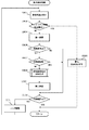
図12は、本実施例における焦点検出処理を示すフローチャートである。図12のフローチャートでは、ステップS507以外のステップは、実施例1で説明した図4のフローチャートと同じステップ番号であり、それらの説明を省略する。図12のステップS507では、ステップS304において飽和画素とその近傍画素を含めて演算した第一演算の結果(A像、B像の位相差)が整数値近傍であるか否かの判定を行う。第一演算の結果が整数値近傍である場合は、飽和によるAF誤差が許容できる値と判定し、ステップS311に移行する。一方、第一演算の結果が整数値近傍ではない場合、飽和画素とこれの近傍画素を除外した第二演算を行うために、ステップS306の飽和画素を除外した波形生成に移行する。 FIG. 12 is a flowchart showing the focus detection process in the present embodiment. In the flowchart of FIG. 12, steps other than step S507 are the same step numbers as those of the flowchart of FIG. 4 described in the first embodiment, and the description thereof is omitted. In step S507 of FIG. 12, it is determined whether or not the result of the first calculation (including the phase difference between the A and B images) including the saturated pixel and its neighboring pixels in step S304 is in the vicinity of the integer value. If the result of the first calculation is close to the integer value, it is determined that the AF error due to saturation is acceptable, and the process proceeds to step S311. On the other hand, when the result of the first calculation is not in the vicinity of the integer value, in order to perform the second calculation excluding the saturated pixels and the neighboring pixels, the process proceeds to waveform generation excluding the saturated pixels in step S306.
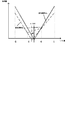
ここで、ステップS304の第一演算結果(位相差)による判定の閾値について図13により説明する。図13は、第一演算結果のAF誤差を示す図である。横軸は第一演算結果、縦軸は実際のA像、B像の位相差を示している。誤差がない場合は、第一演算結果とA像、B像の位相差の関係は傾き1の直線になる。しかし実際には、飽和画素の影響により破線の領域内でAF誤差が生じてしまう。飽和により発生するAF誤差の特徴としては、位相差が整数である1bit、2bitではAF誤差が生じず、正しい演算結果を得ることが出来る。一方、0.5bit単位の位相差に近づくにつれて、AF誤差が大きくなる。ここでの判定値として、AF誤差の範囲を焦点検出の合焦範囲である1/4Fδとする。AF誤差をデフォーカス量換算して、1/4Fδ以内であればそのまま第一演算結果を選択する。一方、AF誤差が1/4Fδより大きければ前述した第二演算結果を用いる。 Here, the determination threshold value based on the first calculation result (phase difference) in step S304 will be described with reference to FIG. FIG. 13 is a diagram illustrating the AF error of the first calculation result. The horizontal axis represents the first calculation result, and the vertical axis represents the actual phase difference between the A and B images. When there is no error, the relationship between the first calculation result and the phase difference between the A and B images is a straight line with a slope of 1. However, in practice, an AF error occurs in the area of the broken line due to the influence of the saturated pixel. As a feature of AF error generated by saturation, AF error does not occur in 1 bit and 2 bit in which the phase difference is an integer, and a correct calculation result can be obtained. On the other hand, as the phase difference approaches 0.5 bits, the AF error increases. As the determination value here, the AF error range is set to 1/4 Fδ which is the focus detection focus range. When the AF error is converted into a defocus amount and within 1 / 4Fδ, the first calculation result is selected as it is. On the other hand, if the AF error is larger than 1 / 4Fδ, the second calculation result described above is used.
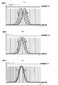
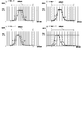
位相差によってAF誤差の大きさが変化する原理について、図13〜図19を用いて説明する。図14は、A像、B像の位相差が−0.5bitである像信号において、相関演算する際に生成する4つのシフト波形を示している。横軸は画素位置、縦軸は像信号のレベルを示している。図14は、波形のシフト量がそれぞれ(a):シフト量k=1、(b):シフト量k=0、(c):シフト量k=−1、(d):シフト量k=−2の4つのシフト波形を示している。それぞれの波形において、●はA像の画素信号、○はB像の画素信号、▲はA像、B像が重なっている画素信号を示している。図14のシフト波形は、A像、B像共に飽和レベルを超えていない波形である。それぞれのシフト波形に対して式(1)より相関量を求める。 The principle that the magnitude of the AF error changes depending on the phase difference will be described with reference to FIGS. FIG. 14 shows four shift waveforms generated when correlation calculation is performed on an image signal in which the phase difference between the A image and the B image is −0.5 bit. The horizontal axis indicates the pixel position, and the vertical axis indicates the level of the image signal. In FIG. 14, the waveform shift amounts are (a): shift amount k = 1, (b): shift amount k = 0, (c): shift amount k = −1, and (d): shift amount k = −. 2 shows four shift waveforms. In each waveform, ● represents a pixel signal of the A image, ○ represents a pixel signal of the B image, and ▲ represents a pixel signal where the A image and the B image overlap. The shift waveform in FIG. 14 is a waveform in which both the A image and the B image do not exceed the saturation level. For each shift waveform, the correlation amount is obtained from equation (1).
図15では、図14の像信号はそのままで飽和レベルを低くすることにより、A像、B像の一部の画素信号が飽和レベルを超えた場合を想定する。もちろん、飽和レベルはそのままで、信号レベルを上げても同様の現象が起きる。飽和レベルを超える信号量を持つ画素は全て飽和画素とし、飽和レベルより高い信号量を持っている飽和画素の信号量は、飽和レベルにクリップされてしまう。そのため、飽和がない本来の信号量よりも減少する。 In FIG. 15, it is assumed that a part of the pixel signals of the A image and the B image exceeds the saturation level by lowering the saturation level while keeping the image signal of FIG. 14 as it is. Of course, the same phenomenon occurs even if the signal level is raised without changing the saturation level. All pixels having a signal amount exceeding the saturation level are assumed to be saturated pixels, and the signal amount of a saturated pixel having a signal amount higher than the saturation level is clipped to the saturation level. For this reason, the signal amount is reduced from the original signal amount without saturation.
図16は、飽和画素なしの相関量と、飽和画素ありの相関量を示した図である。図16において、シフト量−2のシフト波形の相関量を式(1)より算出した値をC(−2)とし、C(−2)とC(−1)をつないだ直線と、C(0)とC(1)をつないだ直線との交点を極小値として、位相差を算出する。図16より、飽和画素なしのシフト波形から算出した位相差に対して、飽和画素ありのシフト波形から算出した位相差はズレていることが分かる。このズレはAF誤差である。 FIG. 16 is a diagram illustrating a correlation amount without saturated pixels and a correlation amount with saturated pixels. In FIG. 16, a value obtained by calculating the correlation amount of the shift waveform of the shift amount −2 from the equation (1) is C (−2), a straight line connecting C (−2) and C (−1), and C ( The phase difference is calculated with the intersection between the straight line connecting 0) and C (1) as the minimum value. It can be seen from FIG. 16 that the phase difference calculated from the shift waveform with saturated pixels is shifted from the phase difference calculated from the shift waveform without saturated pixels. This deviation is an AF error.
このAF誤差の原因として、図14(a)と図15(a)の10画素目と12画素目に注目すると、飽和によるクリップがない図14(a)と比べて、飽和によるクリップがある図15(a)はA像、B像の信号量の差が減少していることがある。A像、B像の信号量の差は相関量になるので、飽和がないときに比べて、飽和ありの像信号の相関量は少なくなる。図16より、シフト量k=0の場合は、k=−2、−1、1の場合と比較して、飽和によって相関量が減少している量が少ない。これは、シフト量0bitのシフト波形である図14(b、図15(b)に注目して分かるように、10画素目と11画素目は飽和により飽和レベルにクリップされるが、相関量に及ぼす影響は他のシフト波形と比較すると少ないことに起因する。このように、シフト波形毎に、飽和の影響による相関量の減少量が異なるため、それぞれのシフト波形から補間演算することで位相差を求めると正しい結果が得られず、AF誤差が生じてしまう。補間演算する際、整数bitから最も離れている0.5bit付近に極小値がある場合に、最も相関量の変動の影響を受けやすくなる。このように、位相差の小数部が0.5bitである像信号を演算した場合、AF誤差が最も大きくなる。 As a cause of this AF error, when attention is paid to the 10th pixel and the 12th pixel in FIGS. 14 (a) and 15 (a), there is a clip due to saturation compared to FIG. 14 (a) where there is no clip due to saturation. In 15 (a), the difference in signal amount between the A and B images may be reduced. Since the difference between the signal amounts of the A image and the B image is a correlation amount, the correlation amount of the image signal with saturation is smaller than when there is no saturation. As shown in FIG. 16, when the shift amount k = 0, the amount of decrease in the correlation amount due to saturation is smaller than when k = −2, −1, and 1. As can be seen from FIGS. 14B and 15B, which are shift waveforms with a shift amount of 0 bits, the 10th and 11th pixels are clipped to saturation level due to saturation, but the correlation amount The effect of this effect is small compared to other shift waveforms, and the amount of decrease in correlation due to the influence of saturation differs for each shift waveform in this way. If a minimum value is found in the vicinity of 0.5 bit, which is farthest from the integer bit, interpolation results are most affected by the fluctuation of the correlation amount. As described above, when an image signal having a fractional phase difference of 0.5 bits is calculated, the AF error becomes the largest.
一方で、位相差が整数bitの場合について図17、18、19を用いて説明する。図17では、A像、B像の位相差が−1bitである像信号の4つのシフト波形を示しており、位相差以外の振幅、像信号は図14と同様の波形である。飽和レベルは、図17と同様に飽和画素が生じないような、像信号の最大値よりも大きい値とする。図18は、図17の像信号はそのままで飽和レベルを低くすることにより、A像、B像の一部の画素信号が飽和レベルを超えた場合を想定している。 On the other hand, the case where the phase difference is an integer bit will be described with reference to FIGS. FIG. 17 shows four shift waveforms of an image signal in which the phase difference between the A image and the B image is −1 bit. The amplitude and image signal other than the phase difference have the same waveforms as those in FIG. As in FIG. 17, the saturation level is set to a value larger than the maximum value of the image signal so that no saturated pixel is generated. FIG. 18 assumes a case where a part of pixel signals of the A and B images exceeds the saturation level by lowering the saturation level while keeping the image signal of FIG. 17 as it is.
図19には、図17と図18のシフト波形から求めた相関量を示す。図19においても、図16と同様にして相関量の極小値を求め、位相差を算出する。A像、B像の位相差が整数である像信号の相関量を示している図19では、飽和画素の有無に関わらず同じ位相差を示し、AF誤差は生じていない。この理由は、図18(b)に着目すると分かるように、A像、B像の位相差が整数であるため、飽和画素に関わらずA像とB像が重なるからである。A像、B像の像信号が完全に同じとすると、A像、B像が重なったシフト波形の相関量は0となる。相関量は負の値をとらないため、極小値は像が一致したシフト量になる。したがって、上述したように、像信号が一致するシフト量は飽和画素とは関係がないため、飽和画素の存在に関わらず、正しい位相差を算出することが出来る。 FIG. 19 shows the correlation amount obtained from the shift waveforms in FIGS. 17 and 18. Also in FIG. 19, the minimum value of the correlation amount is obtained in the same manner as in FIG. 16, and the phase difference is calculated. In FIG. 19, which shows the correlation amount of image signals in which the phase difference between the A and B images is an integer, the same phase difference is shown regardless of the presence or absence of saturated pixels, and no AF error occurs. This is because, as can be seen from FIG. 18B, the phase difference between the A image and the B image is an integer, so the A image and the B image overlap regardless of the saturation pixel. If the image signals of the A and B images are completely the same, the correlation amount of the shift waveform in which the A and B images overlap is zero. Since the correlation amount does not take a negative value, the minimum value is a shift amount in which images match. Therefore, as described above, the shift amount with which the image signals match is not related to the saturated pixel, so that a correct phase difference can be calculated regardless of the presence of the saturated pixel.
また、実際の演算では、シフト波形毎の相関量から直線補間を行う。図18(a)、(c)が示すように、像信号が一致している図18(b)の波形に対し、左右にシフトした(a)と(c)の波形は、A像とB像が入れ替わっただけである。そのため、(a)と(c)のシフト波形における相関量は同じ値である。したがって、図19において、上述したように極小値を算出すると飽和画素の有無に関わらずシフト量k=−1で極値を持つ。以上の原理により、A像、B像の位相差が整数値の場合は、AF誤差は生じず、位相差が整数の間で小数部が0.5bitである値に近づくにつれて、第一演算結果のAF誤差は大きくなる。 In actual calculation, linear interpolation is performed from the correlation amount for each shift waveform. As shown in FIGS. 18 (a) and 18 (c), the waveforms of (a) and (c) shifted to the left and right with respect to the waveform of FIG. The statue was just replaced. Therefore, the correlation amounts in the shift waveforms of (a) and (c) are the same value. Therefore, in FIG. 19, when the minimum value is calculated as described above, it has an extreme value with the shift amount k = −1 regardless of the presence or absence of saturated pixels. Based on the above principle, when the phase difference between the A and B images is an integer value, no AF error occurs, and the first calculation result as the phase difference approaches a value between the integers and the fractional part is 0.5 bits. The AF error of increases.
上記実施例1によれば、像信号に飽和画素が存在した場合、第一演算結果から飽和画素除外波形を生成し、生成した波形を基に第二演算を行っている。つまり、第二演算を行う場合は、相関演算を二回行う必要がある。そこで、実施例2では、第一演算結果より、位相差が整数値近傍である場合は、AF誤差が少ないと判定し(S507)、第二演算を行わず、第一演算結果から焦点検出を行う。このことで、焦点検出処理にかかる時間を短縮し、かつ高精度で焦点検出を行うことが出来る。 According to the first embodiment, when a saturated pixel exists in the image signal, a saturated pixel excluded waveform is generated from the first calculation result, and the second calculation is performed based on the generated waveform. That is, when performing the second calculation, the correlation calculation needs to be performed twice. Therefore, in the second embodiment, when the phase difference is close to the integer value from the first calculation result, it is determined that the AF error is small (S507), and the second calculation is not performed, and the focus detection is performed from the first calculation result. Do. As a result, the time required for the focus detection process can be shortened and the focus detection can be performed with high accuracy.
(実施例3)
実施例3は、実施例1の考え方と実施例2の考え方を組み合わせた演算切替の判定方法を採用する。実施例3におけるカメラ100の構成(図1)と撮影動作(図3)については、上記実施例1と同様なので、それらの説明は省略する。図20は、本実施例における焦点検出処理を示すフローチャートである。なお、図20のフローチャートでは、演算切替判定部のステップS601〜S607以外のステップについては、図4のフローチャートと同じステップ番号であり、それらの説明を省略する。
(Example 3)
The third embodiment employs a calculation switching determination method that combines the concept of the first embodiment and the concept of the second embodiment. Since the configuration (FIG. 1) and the shooting operation (FIG. 3) of the
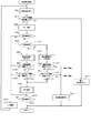
図20のステップS601では、先に算出した第一演算(飽和画素を含む像信号による位相差演算)の結果が整数値近傍であるか否かの判定を行う。ここでの判定は前述の実施例2で説明したのと同様であり、第一演算の結果が整数値近傍でAF誤差が1/4Fδ以内である場合は、ステップS602に移行する。一方、第一演算の結果が整数値近傍ではなくAF誤差が1/4Fδより大きい場合は、ステップS605に移行する。ステップS602では、実施例1のステップS306と同様の飽和画素を除外した波形生成を行う。飽和画素除外の波形生成は、第一演算の補間演算で使用した4つのシフト波形と、ステップS305で検出した飽和画素情報から、飽和画素を除外した波形を生成する。ここでは、4つのシフト波形から飽和画素とその近傍画素が除外される。 In step S601 in FIG. 20, it is determined whether or not the result of the first calculation (phase difference calculation based on an image signal including a saturated pixel) calculated before is an integer value. The determination here is the same as that described in the second embodiment. If the result of the first calculation is near the integer value and the AF error is within 1 / 4Fδ, the process proceeds to step S602. On the other hand, if the result of the first calculation is not near the integer value and the AF error is greater than 1 / 4Fδ, the process proceeds to step S605. In step S602, the same waveform generation as that in step S306 of the first embodiment is performed except for the saturated pixels. Saturated pixel exclusion waveform generation generates a waveform excluding saturated pixels from the four shift waveforms used in the first interpolation operation and the saturated pixel information detected in step S305. Here, the saturated pixel and its neighboring pixels are excluded from the four shift waveforms.
ステップS603では、ステップS602で生成した除外波形の演算画素数が閾値1(第一閾値)以下であるか否かの判定を行う。演算画素数が閾値1より多い場合は、演算画素数による判定においては第二演算が有効であると判定し、ステップS604のコントラストによる判定に移行する。一方、演算画素数が閾値1以下の場合は、第二演算が有効ではないと判定し、第一演算の結果を用いるステップS310の合焦判定に移行する。なお、ここでの閾値1の決定方法については後述する。
In step S603, it is determined whether or not the number of calculation pixels of the excluded waveform generated in step S602 is equal to or less than threshold value 1 (first threshold value). When the number of calculation pixels is larger than the
ステップS604では、除外波形のコントラスト情報が閾値2(第2閾値)以下であるか否かの判定を行う。コントラスト情報は実施例1で述べた通り、式(2)より求める。コントラスト情報が閾値2より大きい場合は、第二演算が有効であると判定し、ステップS309の第二演算に移行する。一方、コントラスト情報が閾値2以下の場合は、第二演算が有効ではないと判定し、第一演算の結果を用いるステップS310の合焦判定に移行する。
In step S604, it is determined whether or not the contrast information of the excluded waveform is equal to or less than threshold value 2 (second threshold value). As described in the first embodiment, the contrast information is obtained from the equation (2). If the contrast information is greater than the
ここで、ステップS603とS604の閾値の決定方法について説明する。ステップS601の位相差の判定により、第一演算結果のAF誤差は、図13より、1/4Fδ以内である。そこで、さらに精度の高い演算を行うため、第二演算では、AF誤差が1/8Fδ以内になるような、演算画素数とコントラスト情報の閾値を設定し、判定を行う。演算画素数とコントラスト情報が共に判定閾値より大きく、第二演算結果のAF誤差が1/8Fδ以内であると判断された場合は、第二演算を選択する。一方、演算画素数とコントラスト情報のいずれかが判定閾値以下で、第二演算でのAF誤差が1/8Fδより大きくなる場合は、第一演算を選択する。ここにおいて、判定手段は、第一演算手段で検出した位相差が整数値近傍である場合、演算画素数とコントラスト情報の判定項目のうち、少なくとも1つの閾値を変更することができる。これにより、AF誤差の1/8Fδ以内という目標を変更することができる。 Here, the threshold value determination method in steps S603 and S604 will be described. From the determination of the phase difference in step S601, the AF error of the first calculation result is within 1 / 4Fδ from FIG. Therefore, in order to perform calculation with higher accuracy, in the second calculation, determination is performed by setting the number of calculation pixels and a threshold value of contrast information so that the AF error is within 1/8 Fδ. If both the number of calculation pixels and the contrast information are larger than the determination threshold and it is determined that the AF error of the second calculation result is within 1/8 Fδ, the second calculation is selected. On the other hand, if either the number of calculated pixels or the contrast information is equal to or smaller than the determination threshold value and the AF error in the second calculation is greater than 1 / 8Fδ, the first calculation is selected. Here, when the phase difference detected by the first calculation unit is in the vicinity of the integer value, the determination unit can change at least one threshold among the determination items of the number of calculation pixels and the contrast information. Thereby, the target within 1/8 Fδ of the AF error can be changed.
次に、ステップS601で、第一演算の結果が整数値近傍ではなくAF誤差が1/4Fδより大きいと判定された場合について説明する。ステップS605では、ステップS602と同様に飽和画素とその近傍画素を除外する飽和画素除外の波形生成を行う。ステップS606では、ステップS605で生成された除外波形の演算画素数が閾値3(第3閾値)以下であるか否かの判定を行う。演算画素数が閾値3より多い場合は、演算画素数による判定においては第二演算が有効であると判定し、ステップS607のコントラストによる判定に移行する。一方、演算画素数が閾値3以下の場合は、第二演算が有効ではないと判定し、ステップS303に移行する。ステップS303では、焦点検出を行わず、焦点検出が不可能であることをユーザーに警告する。なお、ここでの閾値の決定方法についても後述する。
Next, a case will be described in which it is determined in step S601 that the result of the first calculation is not near the integer value and the AF error is greater than 1 / 4Fδ. In step S605, similarly to step S602, a saturated pixel excluded waveform is generated to exclude the saturated pixel and its neighboring pixels. In step S606, it is determined whether or not the number of calculation pixels of the excluded waveform generated in step S605 is equal to or less than threshold value 3 (third threshold value). When the number of calculation pixels is larger than the
ステップS607では、除外波形のコントラスト情報が閾値4(第4閾値)以下であるか否かの判定を行う。コントラスト情報が閾値4より大きい場合は、第二演算が有効であるとして、ステップS309の第二演算に移行する。一方、コントラスト情報が閾値4以下の場合は、第二演算が有効ではないと判定され、ステップS303に移行する。ステップS303では、焦点検出を行わずに焦点検出が不可能であることをユーザーに警告する。
In step S607, it is determined whether or not the contrast information of the excluded waveform is equal to or less than threshold value 4 (fourth threshold value). If the contrast information is greater than the
ここで、ステップS606とS607の閾値の決定方法について説明する。ステップS601の位相差の判定のより、第一演算結果のAF誤差は、図13より、1/4Fδより大きい。そこで、第二演算ではAF誤差が1/4Fδ以内になるように演算画素数とコントラスト情報の閾値を設定し、判定を行う。演算画素数とコントラスト情報が共に判定閾値を超えて、第二演算結果のAF誤差が1/4Fδ以内であると判断された場合は、第二演算を選択する。一方で、演算画素数とコントラスト情報のいずれかが判定閾値以下で、第二演算でのAF誤差が1/4Fδより大きくなると判断された場合、焦点検出は行わない。 Here, the threshold value determination method in steps S606 and S607 will be described. From the determination of the phase difference in step S601, the AF error of the first calculation result is larger than 1 / 4Fδ from FIG. Therefore, in the second calculation, the number of calculation pixels and the threshold value of contrast information are set so that the AF error is within 1 / 4Fδ, and determination is performed. When both the number of calculation pixels and the contrast information exceed the determination threshold and it is determined that the AF error of the second calculation result is within 1 / 4Fδ, the second calculation is selected. On the other hand, when it is determined that either the number of calculated pixels or the contrast information is equal to or less than the determination threshold and the AF error in the second calculation is greater than 1 / 4Fδ, focus detection is not performed.
上記実施例3によれば、像信号に飽和画素が存在した場合、第一演算結果の位相差によって第一演算のAF誤差を判定する(S601)。判定された第一演算のAF誤差が1/4Fδ以内である場合、信頼性判定の閾値1、2により、第二演算で、さらに高い精度の高い演算が可能であるかを判定している(S603、S604)。一方、判定された第一演算のAF誤差が1/4Fδより大きく焦点検出が行えない場合、信頼性判定の閾値3、4により、第二演算で、AF誤差1/4Fδ以内の精度で演算が可能であるか否かの判定を行う(S606、S607)。この判定により、第二演算による焦点検出が可能あるか否かを判定することが出来る。以上の判定により、様々な被写体状況に対応して、最適な演算を選択し、高精度な焦点検出を行うことが出来る。
According to the third embodiment, when a saturated pixel exists in the image signal, the AF error of the first calculation is determined based on the phase difference of the first calculation result (S601). If the determined AF error of the first calculation is within 1 / 4Fδ, it is determined whether higher-precision calculation can be performed in the second calculation based on the
(実施例4)
実施例4では、撮像素子に焦点検出用画素が離散的に配置された撮像装置における焦点検出処理について説明する。上記実施例1では、メインミラー12がダウン位置に配置され、サブミラー13により光束が焦点検出ユニット7へ入射するような構成であり、イメージセンサ101への光束に対して、所謂2次光学系による位相差検出方式の焦点検出を行っていた。しかし、これに限らず、イメージセンサ101の一部画素を焦点検出用に転用し、その焦点検出用画素にて、撮像面で瞳分割するマスクを配置することで、撮像面における位相差検出方式の焦点検出を行ってもよい。すなわち、実施例4では、受光手段は、画素の光電変換素子が二次元に配置された撮像素子であり、撮像素子の少なくとも一部を焦点検出用画素とし、焦点検出用画素からの像信号を基に位相差を検出することで焦点状態を検出する。
Example 4
In Example 4, focus detection processing in an imaging apparatus in which focus detection pixels are discretely arranged on an imaging element will be described. In the first embodiment, the
焦点検出用画素は、例えば、複数の光電変換部を備え、撮影レンズの瞳上の異なる領域を通過した光束が、それぞれ、異なる光電変換部に導かれるように構成される。各焦点検出用画素に含まれる光電変換部で得た画像信号により、異なる瞳領域を通過した光束により生成される光像(A像とB像)を取得する。そして、上記相関演算式を用いて、このA像とB像の相対的な位相差を算出する。他方、撮像用画素は、例えば、画素内に1つの光電変換部を有する画素である。こうした場合、各焦点検出用画素で取得した信号を用いて焦点検出を行い、撮影用画素で取得した信号を用いて画像を生成できる。また、撮像用画素で取得した信号を用いて、近接する焦点検出用画素の画像用信号を生成してもよい。このような構成とすることで、撮像素子に占める焦点検出用画素の割合を減らすことができ、焦点検出と同時に、高画質な画像を撮像することができる。 The focus detection pixel includes, for example, a plurality of photoelectric conversion units, and is configured such that light beams that have passed through different regions on the pupil of the photographing lens are guided to different photoelectric conversion units, respectively. Optical images (A image and B image) generated by the light fluxes that have passed through different pupil regions are acquired by the image signal obtained by the photoelectric conversion unit included in each focus detection pixel. Then, the relative phase difference between the A image and the B image is calculated using the correlation calculation formula. On the other hand, the imaging pixel is, for example, a pixel having one photoelectric conversion unit in the pixel. In such a case, it is possible to perform focus detection using a signal acquired from each focus detection pixel and generate an image using a signal acquired from the imaging pixel. In addition, an image signal of a focus detection pixel that is close may be generated using a signal acquired by the imaging pixel. With such a configuration, the ratio of focus detection pixels in the image sensor can be reduced, and a high-quality image can be captured simultaneously with focus detection.
図21から図23は、撮像用画素と焦点検出用画素の構造を説明する図である。実施例4においては、2行×2列の4画素のうち、対角2画素にG(緑色)の分光感度を有する画素を配置し、他の2画素にR(赤色)とB(青色)の分光感度を有する画素を各1個配置した、ベイヤー配列が採用されている。そして、ベイヤー配列の間に、後述する構造の焦点検出用画素が所定の規則にて分散配置される。図21に撮像用画素の配置と構造を示す。同図(a)は2行×2列の撮像用画素の平面図である。ベイヤー配列では対角方向にG画素が、他の2画素にRとBの画素が配置される。この2行×2列の構造が繰り返し配置される。同図(a)における断面A−Aを同図(b)に示す。MLは各画素の最前面に配置されたオンチップマイクロレンズ、CFRはRのカラーフィルタ、CFGはGのカラーフィルタである。PDはC−MOSセンサの光電変換部を模式的に示し、CLはC−MOSセンサ内の各種信号を伝達する信号線を形成するための配線層である。TLは撮影光学系を模式的に示し、EPは射出瞳を示す。撮像用画素のオンチップマイクロレンズMLと光電変換部PDは、撮影光学系TLを通過した光束を可能な限り有効に取り込むように構成されている。換言すると、撮影光学系TLの射出瞳EPと光電変換部PDは、マイクロレンズMLにより共役関係にあり、かつ光電変換部の有効面積は大面積に設計される。同図(b)ではR画素の入射光束について説明したが、G画素及びB画素も同一の構造となっている。従って、撮像用のRGB各画素に対応した射出瞳EPは大径となり、被写体からの光束を効率良く取り込んで画像信号のS/Nを向上させている。 FIG. 21 to FIG. 23 are diagrams for explaining the structures of the imaging pixels and the focus detection pixels. In the fourth embodiment, out of 4 pixels of 2 rows × 2 columns, pixels having G (green) spectral sensitivity are arranged in the diagonal 2 pixels, and R (red) and B (blue) are arranged in the other 2 pixels. A Bayer arrangement in which one pixel each having a spectral sensitivity of 1 is arranged is employed. In addition, focus detection pixels having a structure to be described later are distributed and arranged in a predetermined rule between the Bayer arrays. FIG. 21 shows the arrangement and structure of the imaging pixels. FIG. 2A is a plan view of 2 × 2 imaging pixels. In the Bayer array, G pixels are arranged diagonally, and R and B pixels are arranged in the other two pixels. This 2-row × 2-column structure is repeatedly arranged. A cross section AA in FIG. 4A is shown in FIG. ML denotes an on-chip microlens arranged in front of each pixel, the CF R color filters R, is CF G is a color filter of G. PD schematically shows a photoelectric conversion unit of the C-MOS sensor, and CL is a wiring layer for forming signal lines for transmitting various signals in the C-MOS sensor. TL schematically represents the photographing optical system, and EP represents the exit pupil. The on-chip microlens ML and the photoelectric conversion unit PD of the imaging pixel are configured to capture the light beam that has passed through the photographing optical system TL as effectively as possible. In other words, the exit pupil EP of the photographing optical system TL and the photoelectric conversion unit PD are conjugated with each other by the microlens ML, and the effective area of the photoelectric conversion unit is designed to be large. In FIG. 5B, the incident light beam of the R pixel has been described, but the G pixel and the B pixel have the same structure. Accordingly, the exit pupil EP corresponding to each pixel for imaging RGB has a large diameter, and the S / N of the image signal is improved by efficiently capturing the light flux from the subject.
図22は、撮影光学系の水平方向(横方向)に瞳分割を行なうための焦点検出用画素の配置と構造を示す。ここで水平方向あるいは横方向の定義は、撮影光学系の光軸が水平となるようにカメラを構えたとき、該光軸に直交し、かつ水平方向に伸びる直線に沿った方向を指す。同図(a)は、焦点検出用画素を含む2行×2列の画素の平面図である。記録もしくは観賞のための画像信号を得る場合、G画素で輝度情報の主成分を取得する。そして人間の画像認識特性は輝度情報に敏感であるため、G画素が欠損すると画質劣化が認知されやすい。一方で、RもしくはB画素は、色情報(色差情報)を取得する画素であるが、人間の視覚特性は色情報には鈍感であるため、色情報を取得する画素は多少の欠損が生じても画質劣化は認識され難い。そこで本実施例では、2行×2列の画素のうち、G画素は撮像用画素として残し、RとBの画素を焦点検出用画素に置き換える。これを同図(a)においてSHA及びSHBで示す。同図(a)における断面A−Aを同図(b)に示す。マイクロレンズMLと、光電変換部PDは図21(b)に示した撮像用画素と同一構造である。本実施例においては、焦点検出用画素の信号は画像創生には用いないため、色分離用カラーフィルタの代わりに透明膜CFWが配置される。また、撮像素子で瞳分割を行なうため、配線層CLの開口部はマイクロレンズMLの中心線に対して一方向に偏倚している。具体的には、画素SHA及の開口部OPHAは右側に偏倚しているため、撮影光学系TLの左側の射出瞳EPHAを通過した光束を受光する。同様に、画素SHBの開口部OPHBは左側に偏倚しているため、撮影光学系TLの右側の射出瞳EPHBを通過した光束を受光する。よって、画素SHAを水平方向に規則的に配列し、これらの画素群で取得した被写体像をA像とする。また、画素SHBも水平方向に規則的に配列し、これらの画素群で取得した被写体像をB像とし、A像とB像の位相差を検出することで、デフォーカス量が検出できる。上記画素SHA及びSHBでは、撮影画面の横方向に輝度分布を有した被写体、例えば縦線に対しては焦点検出可能であるが、縦方向に輝度分布を有する横線は焦点検出不能である。そこで本実施例では、後者についても焦点検出できるよう、撮影光学系の垂直方向(縦方向)にも瞳分割を行なう画素も備えている。 FIG. 22 shows the arrangement and structure of focus detection pixels for performing pupil division in the horizontal direction (lateral direction) of the photographing optical system. Here, the definition of the horizontal direction or the horizontal direction indicates a direction along a straight line that is orthogonal to the optical axis and extends in the horizontal direction when the camera is held so that the optical axis of the photographing optical system is horizontal. FIG. 5A is a plan view of 2 × 2 pixels including focus detection pixels. When obtaining an image signal for recording or viewing, the main component of luminance information is acquired with G pixels. Since human image recognition characteristics are sensitive to luminance information, image quality degradation is easily recognized when G pixels are lost. On the other hand, the R or B pixel is a pixel that acquires color information (color difference information). However, since human visual characteristics are insensitive to color information, the pixel that acquires color information has some defects. However, image quality degradation is difficult to recognize. Therefore, in this embodiment, among the pixels of 2 rows × 2 columns, the G pixel is left as an imaging pixel, and the R and B pixels are replaced with focus detection pixels. This is indicated by S HA and S HB in FIG. A cross section AA in FIG. 4A is shown in FIG. The microlens ML and the photoelectric conversion unit PD have the same structure as the imaging pixel shown in FIG. In the present embodiment, since the signal from the focus detection pixel is not used for image creation, transparent film CF W instead of a color separation color filter is disposed. Moreover, since pupil division is performed by the image sensor, the opening of the wiring layer CL is biased in one direction with respect to the center line of the microlens ML. Specifically, since the opening OP HA of the pixel S HA and the opening OP HA are biased to the right side, the light beam that has passed through the left exit pupil EP HA of the photographing optical system TL is received. Similarly, since the opening OP HB of the pixel S HB is biased to the left side, the light beam that has passed through the right exit pupil EP HB of the imaging optical system TL is received. Therefore, the pixels SHA are regularly arranged in the horizontal direction, and the subject image acquired by these pixel groups is defined as an A image. Further, the pixels SH B are also regularly arranged in the horizontal direction, the subject image acquired by these pixel groups is set as a B image, and the defocus amount can be detected by detecting the phase difference between the A image and the B image. In the pixels S HA and S HB , focus detection is possible for an object having a luminance distribution in the horizontal direction of the photographing screen, for example, a vertical line, but focus detection is not possible for a horizontal line having a luminance distribution in the vertical direction. . Therefore, in the present embodiment, pixels that perform pupil division are also provided in the vertical direction (longitudinal direction) of the photographing optical system so that the focus can be detected for the latter.
図23と図24は、上記図21と図22で説明した撮像用画素と焦点検出用画素の配置規則を説明する図である。図23は撮像用画素の間に焦点検出用画素を離散的に配置する場合の、最小単位の配置規則を説明するための図である。同図において、10行×10列=100画素を1つのブロックとする。そして一番左上のブロックBLK(1,1)において、一番左下のR画素とB画素を、水平方向に瞳分割を行なう1組の焦点検出用画素SHA及びSHBで置き換える。その右隣りのブロックBLK(1,2)においては、同じく一番左下のR画素とB画素を、垂直方向に瞳分割を行なう1組の焦点検出用画素SVC及びSVDで置き換える。また、最初のブロックBLK(1,1)の下に隣接したブロックBLK(2,1)の画素配列は、ブロックBLK(1,2)と同一とする。そして、その右隣りのブロックBLK(2,2)画素配列は、先頭のブロックBLK(1,1)と同一とする。この配置規則を普遍的に表現すると、ブロックBLK(i,j)において、i+jが偶数なら水平瞳分割用の焦点検出用画素を配置し、i+jが奇数なら垂直瞳分割用の焦点検出用画素を配置することになる。そして、図23の2×2=4ブロック、すなわち20行×20列=400画素の領域を、ブロックの上位の配列単位として、クラスタとする。 FIG. 23 and FIG. 24 are diagrams for explaining the arrangement rules of the imaging pixels and focus detection pixels described in FIG. 21 and FIG. FIG. 23 is a diagram for explaining a minimum unit arrangement rule when focus detection pixels are discretely arranged between imaging pixels. In the figure, 10 rows × 10 columns = 100 pixels are defined as one block. In the upper left block BLK (1, 1), the lower left R pixel and B pixel are replaced with a set of focus detection pixels S HA and S HB that perform pupil division in the horizontal direction. In the block BLK (1, 2) on the right side, the lower left R pixel and B pixel are similarly replaced with a set of focus detection pixels S VC and S VD that perform pupil division in the vertical direction. The pixel arrangement of the block BLK (2, 1) adjacent below the first block BLK (1, 1) is the same as that of the block BLK (1, 2). The pixel arrangement of the block BLK (2, 2) on the right side is the same as that of the leading block BLK (1, 1). Expressing this arrangement rule universally, in block BLK (i, j), if i + j is an even number, horizontal pupil division focus detection pixels are arranged, and if i + j is an odd number, vertical pupil division focus detection pixels are arranged. Will be placed. Then, a 2 × 2 = 4 block of FIG. 23, that is, an area of 20 rows × 20 columns = 400 pixels is defined as a cluster as an upper array unit of the block.
こうして、クラスタを単位とした配置を行い、クラスタが集まって単位としたフィールドを単位とした配置を行う。図24は、撮影光学系によって形成された被写体像の、横ずれ方向の焦点検出を行なう場合の画素グループ化方法を説明する図である。横ずれ方向の焦点検出とは、撮影光学系の射出瞳を横方向に分割するための焦点検出用画素を用いて、位相差演算を行なうことを指す。図24に示す画素配列は、ブロックが集まったクラスタの配置を示す。焦点検出の際には、横方向に1ブロック、縦方向に10ブロックの合計10ブロックを1つのグループとし、これをセクションとする。そして、本実施例では、横方向に並んだ30セクションで、1つの焦点検出領域を構成する。すなわち、100行×300列=3万画素の領域が1つの焦点検出領域となる。この1つの焦点検出領域をAFエリアと定義する。ここで、1つのセクション内においては、横方向における一方の瞳分割を行なう画素SHAが5個、他方の瞳分割を行なう画素SHBも5個含まれている。そこで本実施例においては、5個のSHAの出力を加算して、位相差演算用の一方の画像信号(A像)の1AF画素とする。同様に、5個のSHBの出力を加算して、位相差演算用の他方の画像信号(B像)の1AF画素とする。撮影光学系によって形成された被写体像の、縦ずれ方向の焦点検出を行なう場合の画素グループ化方法も原理は同じである。 In this way, arrangement is performed in units of clusters, and arrangement is performed in units of fields in which clusters are gathered as units. FIG. 24 is a diagram for explaining a pixel grouping method in the case of performing focus detection in the lateral shift direction of the subject image formed by the photographing optical system. The focus detection in the lateral shift direction refers to performing a phase difference calculation using focus detection pixels for dividing the exit pupil of the photographing optical system in the horizontal direction. The pixel array shown in FIG. 24 shows the arrangement of clusters in which blocks are gathered. At the time of focus detection, a total of 10 blocks of 1 block in the horizontal direction and 10 blocks in the vertical direction are grouped into one group. In this embodiment, one focus detection area is configured by 30 sections arranged in the horizontal direction. That is, an area of 100 rows × 300 columns = 30,000 pixels is one focus detection area. This one focus detection area is defined as an AF area. Here, in one section, five pixels S HA that perform one pupil division in the horizontal direction and five pixels S HB that perform the other pupil division are included. Therefore, in this embodiment, the outputs of the five SHAs are added to form one AF pixel of one image signal (A image) for phase difference calculation. Similarly, the outputs of the five SHBs are added to form 1AF pixel of the other image signal (B image) for phase difference calculation. The principle of the pixel grouping method in the case of performing focus detection in the direction of longitudinal shift of the subject image formed by the photographing optical system is the same.
図25から図27は、本実施例に関わる撮影動作及び焦点検出処理を説明するためのフローチャートである。図25は本実施例のカメラの撮影動作フローである。撮影者がカメラの電源スイッチをオン操作すると、ステップS701においては目標露光値を適正露光値に設定する。また、その他に、メモリ内容や実行プログラムの初期化を行なうと共に、撮影準備動作を実行する。ステップS702では撮像素子の撮像動作を開始する。ここではステップS701、あるいは後述するステップS705で設定された目標露光値になるように露光時間を制御し、プレビュー用の低画素動画像を出力する。ステップS703では読み出した動画をカメラ背面に設けられた表示器17に表示し、撮影者はこのプレビュー画像を目視して撮影時の構図決定を行なう。ステップS704では、SW1_18がオン操作されたか否かを判別し、オン操作されていなければステップS702に戻る。そして、撮像素子駆動からステップS703のプレビュー画像表示を繰り返し実行する。ステップS704でSW1_18がオン操作されるとステップS705に移行し、焦点検出処理を実行する。ステップS705で行う焦点検出処理は、図27のフローチャートを用いて説明する。
FIGS. 25 to 27 are flowcharts for explaining the photographing operation and the focus detection process according to the present embodiment. FIG. 25 is a flowchart of the photographing operation of the camera of this embodiment. When the photographer turns on the power switch of the camera, the target exposure value is set to an appropriate exposure value in step S701. In addition, the memory contents and the execution program are initialized and the shooting preparation operation is executed. In step S702, the imaging operation of the image sensor is started. Here, the exposure time is controlled so that the target exposure value set in step S701 or step S705 described later is obtained, and a low-pixel moving image for preview is output. In step S703, the read moving image is displayed on the
図27は、本発実施例における焦点検出処理を示すフローチャートである。ステップS901では、MPU6は101のC−MOSセンサに対して、信号蓄積指示を出力する。指示に基づき、C−MOSセンサは信号蓄積動作を開始する。そして、蓄積動作が終了すると焦点検出用画素を読み出す。次にステップS902では、ステップS901で焦点検出用画素から出力された像信号から得たコントラスト情報が所定量以下であるか否かの判定を行う。コントラスト情報が所定量以下の場合は、ステップS916に移行し、焦点検出を行わず、焦点検出が不可能であることをユーザーに警告する。一方、コントラスト情報が所定量より大きい場合、ステップS903の第一演算に移行する。ここで、コントラスト情報とは、実施例1と同様に、像信号の演算画素範囲において、AF画素の隣接したAF画素の画素信号の差分を二乗した値の総和である。コントラスト情報が小さい場合、位相差を検出する際、相関量も小さくなる。したがって、画素に発生するノイズ成分の影響を受けやすく焦点検出の精度が悪化する。以上の理由からコントラスト情報が小さく焦点検出の信頼性が十分ではない場合は、焦点検出を行わない。次にステップS903では、MPU6はA像、B像を基に、実施例1と同様の第一演算を行う。C−MOSセンサのAF画素から取得した像信号のシフトさせた波形をシフト波形とする。相関演算式(1)を用いて、それぞれのシフト波形から相関量C(k)を演算し、像信号の位相差を算出する。
FIG. 27 is a flowchart showing focus detection processing in the present embodiment. In step S901, the
次にステップS904では、MPU6は、ステップS901で取得した一対の像信号における異常画素(飽和画素、欠陥画素)を検出する。ここでは異常画素として飽和画素を検出する。実施例4において、AF画素は複数の焦点検出用画素の出力を加算する構成になっている。ここで定義する飽和画素は、AF画素単位に含まれる焦点検出用画素(SCTV・SCTH)に1つでも飽和画素が含まれていた場合、そのAF画素は飽和画素として扱う。次に、検出した情報を基に飽和画素が存在するか否かの判定を行う。飽和画素が存在しない場合は、ステップS913の合焦判定に移行する。一方、飽和画素が存在する場合はステップS905のA像、B像の位相差による判定に移行する。ステップS905での位相差による判定は実施例2、3でも説明した通りであり、先に算出した第一演算の結果が整数値近傍であるか否かの判定を行う。ここでの判定は第一演算の結果が整数値近傍でAF誤差が1/4Fδ以内である場合は、ステップS906に移行する。一方、第一演算の結果が整数値近傍ではなくAF誤差が1/4Fδより大きい場合は、ステップS909に移行する。ステップS906では、実施例1のステップS306と同様の飽和画素除外の波形生成を行う。飽和画素除外の波形生成は、第一演算の補間演算で使用した4つのシフト波形と、ステップS904で検出した飽和画素情報から、飽和画素の除外波形を生成する。ここでは、4つのシフト波形から飽和した画素信号とその近傍画素の信号が除外される。
Next, in step S904, the
ステップS907では、除外波形の演算画素数が閾値1以下であるか否かの判定を行う。演算画素数が閾値1より多い場合は、演算画素数による判定においては、実施例1で説明した第二演算が有効であると判定し、ステップS908のコントラストによる判定に移行する。一方、演算画素数が閾値1以下の場合は、第二演算が有効ではないと判定し、第一演算の結果を用いてステップS913の合焦判定に移行する。ステップS908では、除外波形のコントラスト情報が閾値2以下であるか否かの判定を行う。コントラスト情報は実施例1で述べた通り、上記式(2)より求める。コントラスト情報が閾値2より大きい場合は、第二演算が有効であると判定し、ステップS912の第二演算に移行する。一方、コントラスト情報が閾値2以下の場合は、第二演算が有効ではないと判定し、第一演算の結果を用いてステップS913の合焦判定に移行する。ここで、ステップS907とS908の閾値の決定方法については実施例3のステップS603、S604と同じものとする。ステップS909では、ステップS906と同様に飽和画素とその近傍画素を除外する飽和画素除外の波形生成を行う。
In step S907, it is determined whether or not the number of calculation pixels of the excluded waveform is equal to or less than the
ステップS910では、除外波形の演算画素数が閾値3以下であるか否かの判定を行う。演算画素数が閾値3より多い場合は、演算画素数による判定においては第二演算が有効であると判定し、ステップS911のコントラストによる判定に移行する。一方、演算画素数が閾値3以下の場合は、第二演算が有効ではないと判定し、ステップS915に移行する。ステップS915では、焦点検出を行わず、図25のステップS702で撮像素子の駆動に関わる目標露光値を1EV分アンダーに変更する。ステップS911では、除外波形のコントラスト情報が閾値4以下であるか否かの判定を行う。コントラスト情報が閾値4より大きい場合は、第二演算が有効であるとして、ステップS912の第二演算に移行する。一方、コントラスト情報が閾値4以下の場合は、第二演算が有効ではないと判定され、ステップS915に移行する。ステップS908もしくはS911で、コントラスト情報がそれぞれで決められた閾値以上であると判定された場合、ステップS912で飽和画素とその近傍画素を除外した除外波形から演算する第二演算を行う。ステップS913では、ステップS903もしくはステップS912で算出された位相差が所定の範囲内であるか否かの判定を行う。ステップS914では、位相差の情報に基づき、レンズ駆動量を算出し、レンズ駆動制御を行い、ステップS901に戻り、合焦状態になるまで前述の動作が繰り返される。ここで、ステップS910とS911の閾値の決定方法は実施例3のステップS606、S607と同じものとする。ステップS915では、目標露光値を1EV分アンダーに設定する。そのため次回の焦点検出処理の際、焦点検出用画素の飽和量を改善できる。
In step S910, it is determined whether or not the number of calculation pixels of the excluded waveform is equal to or less than the
図25の撮影動作フローの説明に戻る。ステップS706では、目標露光値の変更を行ったか否かの判定を行う。目標露光値の変更が行われていない場合は、ステップS707のSW2_19の判定に移行する。一方、目標露光値の変更が行われている場合は、変更された目標露光値に基づいて撮像素子を駆動させる。ステップS707では、SW2_19がオン操作されたか否かを判別し、オン操作されていなければステップS702の撮像素子駆動へ戻る。一方、ステップS708でSW2_19がオン操作されるとステップS708に移行し、撮影サブルーチンを実行する。 Returning to the description of the shooting operation flow of FIG. In step S706, it is determined whether or not the target exposure value has been changed. If the target exposure value has not been changed, the process proceeds to the determination of SW2_19 in step S707. On the other hand, when the target exposure value is changed, the image sensor is driven based on the changed target exposure value. In step S707, it is determined whether or not the SW2_19 is turned on. If the SW2_19 is not turned on, the process returns to the image sensor driving in step S702. On the other hand, when SW2_19 is turned on in step S708, the process proceeds to step S708, and an imaging subroutine is executed.
図26は撮影サブルーチンのフロー図である。撮影開始スイッチが操作されると、ステップS801では適正露光値であるか否かの判定を行う。メインフローのステップS705で目標露光値が変更され、ステップS701で設定した適正露光値とは異なる露光値でプレビュー画像に出力されていた場合、ステップS802の露光値変更に移行する。一方、適正露光値で出力されている場合はステップS803の絞り・シャッター駆動へ移行する。ステップS802では、焦点検出を行うために変更された目標露光値を、適正露光値に変更し、ステップS803の動作に備える。ステップS803では光量調節絞りを駆動し、露光時間を規定するメカニカルシャッタの開口制御を行なう。ステップS804では、高画素静止画撮影のための画像読み出し、すなわち全画素の読み出しを行なう。ステップS805では読み出した画像信号の欠損画素補間を行なう。すなわち、焦点検出用画素の出力は撮像のためのRGBカラー情報を有しておらず、画像を得る上では欠陥画素に相当するため、周囲の撮像用画素の情報から補間により画像信号を創生する。ステップS806では、画像のγ補正、エッジ強調等の画像処理を行い、ステップS807において、フラッシュメモリ23に撮影画像を記録する。ステップS808では、表示器17に撮影済み画像を表示し、図25の撮影動作フローにリターンする。図25の撮影動作フローに戻り、一連の撮影動作を終了する。
FIG. 26 is a flowchart of the photographing subroutine. When the shooting start switch is operated, it is determined in step S801 whether the exposure value is appropriate. If the target exposure value is changed in step S705 of the main flow and the preview image is output with an exposure value different from the appropriate exposure value set in step S701, the process proceeds to exposure value change in step S802. On the other hand, if it is output with a proper exposure value, the process proceeds to aperture / shutter drive in step S803. In step S802, the target exposure value changed to perform focus detection is changed to an appropriate exposure value to prepare for the operation in step S803. In step S803, the light quantity adjusting diaphragm is driven to perform opening control of the mechanical shutter that defines the exposure time. In step S804, image reading for high-pixel still image shooting, that is, reading of all pixels is performed. In step S805, defective pixel interpolation of the read image signal is performed. That is, the output of the focus detection pixel does not have RGB color information for imaging, and corresponds to a defective pixel in obtaining an image. Therefore, an image signal is created by interpolation from information on surrounding imaging pixels. To do. In step S806, image processing such as γ correction and edge enhancement of the image is performed, and in step S807, the captured image is recorded in the
以上説明したように、ライブビュー撮影の時、撮像面全体から露光値を決定するため、焦点検出範囲の一部に明るい被写体が存在した場合、焦点検出用画素が飽和してしまい、焦点検出の精度が悪化してしまう。一方、焦点検出範囲に飽和画素が発生しないように目標露光値を暗くしてしまうと、プレビュー画面が暗くなってしまい、撮影者は構図を定める際の障害になってしまう。そこで、飽和画素が発生しても可能な限り露光値を変更せず、実施例3と同様、位相差、演算画素数、コントラスト情報から最適な演算を選択して焦点検出処理を行う(S903〜S915)。 As described above, since the exposure value is determined from the entire imaging surface at the time of live view shooting, if a bright subject exists in a part of the focus detection range, the focus detection pixels are saturated, and focus detection is performed. Accuracy will deteriorate. On the other hand, if the target exposure value is darkened so that saturated pixels do not occur in the focus detection range, the preview screen becomes dark, and the photographer becomes an obstacle in determining the composition. Therefore, even if a saturated pixel occurs, the exposure value is not changed as much as possible, and the focus detection process is performed by selecting an optimal calculation from the phase difference, the number of calculation pixels, and the contrast information as in the third embodiment (S903-S3). S915).
(他の実施形態)
本発明の目的は、以下の実施形態によって達成することもできる。即ち、前述した実施例の機能(カメラ側MPUなどの制御手段などの機能)を実現するソフトウェアのプログラムコードを格納した記憶媒体を、焦点検出装置に供給する。そして、そのカメラコントローラのコンピュータ(またはCPU、MPUなど)が記憶媒体に格納されたプログラムコードを読み出し上記機能を実行する。この場合、記憶媒体から読み出されたプログラムコード自体が上記実施例の機能を実現することになり、被写体に対する異なる視点にて取得した視差画像信号に基づき焦点検出を行うためのプログラム、これを格納した記憶媒体は本発明を構成することになる。詳細には、少なくとも1対の複数画素からなるセンサを用いて位相差検出方式の焦点検出を行う焦点検出方法は次のステップを有する。撮影光学系の一対の瞳領域を通過した光束により形成される一対の被写体の像信号を受光し、出力する出力ステップ。前記出力ステップで出力される像信号で形成される一対の画素信号列に含まれる異常信号を発生する異常画素を検出する異常画素検出ステップ。前記異常画素検出ステップで検出された異常画素による信号を含んだ一対の画素信号列の位相差を検出する第一演算ステップ。異常画素による信号を除外した一対の画素信号列の位相差を検出する第二演算ステップ。前記第一演算ステップと前記第二演算ステップの結果のいずれか一方を所定の判定基準に基づいて選択する判定ステップ。前記判定ステップにより選択された結果を基に焦点状態を検出する焦点検出ステップ。
(Other embodiments)
The object of the present invention can also be achieved by the following embodiments. That is, a storage medium storing software program codes for realizing the functions of the above-described embodiments (functions of control means such as the camera side MPU) is supplied to the focus detection apparatus. Then, the computer (or CPU, MPU, etc.) of the camera controller reads the program code stored in the storage medium and executes the above function. In this case, the program code itself read from the storage medium realizes the functions of the above-described embodiment, and stores a program for performing focus detection based on parallax image signals acquired from different viewpoints with respect to the subject. This storage medium constitutes the present invention. Specifically, a focus detection method that performs focus detection by a phase difference detection method using a sensor composed of at least one pair of a plurality of pixels includes the following steps. An output step of receiving and outputting an image signal of a pair of subjects formed by a light beam that has passed through a pair of pupil regions of the photographing optical system. An abnormal pixel detection step of detecting an abnormal pixel that generates an abnormal signal included in a pair of pixel signal sequences formed by the image signal output in the output step. First Starring Sanz step for detecting a phase difference between a pair of pixel signal sequence including the signal according to the detected abnormal pixel by said abnormal pixel detecting step. A second calculation step of detecting a phase difference between a pair of pixel signal sequences excluding signals due to abnormal pixels. A determination step of selecting one of the results of the first calculation step and the second calculation step based on a predetermined determination criterion. A focus detection step of detecting a focus state based on the result selected in the determination step;
上述した本発明による焦点検出装置及び方法は、焦点検出装置を必要とするデジタルカメラなどの撮像装置等に用いることができる。本発明の好ましい実施形態について説明したが、本発明はこれらの実施形態に限定されず、その要旨の範囲内で種々の変形及び変更が可能である。 The above-described focus detection apparatus and method according to the present invention can be used for an imaging apparatus such as a digital camera that requires a focus detection apparatus. Although preferable embodiment of this invention was described, this invention is not limited to these embodiment, A various deformation | transformation and change are possible within the range of the summary.
1・・レンズ側MPU、6・・カメラ側MPU、7・・焦点検出ユニット(焦点検出装置)、20・・撮影レンズユニット、30・・カメラ本体、100・・カメラ(撮像装置)、101・・撮像素子(受光手段)、107・・焦点検出センサ(受光手段)、111・・異常画素検出部(異常画素検出手段)、112・・相関演算部(第一演算手段、第二演算手段)、113・・演算切替判定部(判定手段) 1 ·· Lens side MPU, 6 ·· Camera side MPU, 7 ·· Focus detection unit (focus detection device), 20 ·· Lensing lens unit, 30 ·· Camera body, 100 ·· Camera (imaging device), 101 · · Image sensor (light receiving means) 107 · · Focus detection sensor (light receiving means) 111 · · Abnormal pixel detection unit (abnormal pixel detection unit) 112 · · Correlation calculation unit (first calculation unit, second calculation unit) , 113 .. Operation switching determination unit (determination means)
Claims (12)
前記受光手段から出力される像信号で形成される一対の画素信号列に含まれる異常信号を発生する異常画素を検出する異常画素検出手段と、
前記異常画素検出手段により検出された異常画素による信号を含んだ一対の画素信号列の位相差を検出する第一演算手段と、
異常画素による信号を除外した一対の画素信号列の位相差を検出する第二演算手段と、
前記第一演算手段と前記第二演算手段からの結果のいずれか一方を選択する判定手段と、
を備え、
前記判定手段により選択された結果を基に焦点状態を検出することを特徴とする焦点検出装置。 A light receiving means including a plurality of pixels that receive and output an image signal of a pair of subjects formed by a light beam that has passed through a pair of pupil regions of the photographing optical system;
An abnormal pixel detecting means for detecting an abnormal pixel that generates an abnormal signal included in a pair of pixel signal sequences formed by an image signal output from the light receiving means;
First calculation means for detecting a phase difference between a pair of pixel signal sequences including a signal from an abnormal pixel detected by the abnormal pixel detection means;
Second computing means for detecting a phase difference between a pair of pixel signal sequences excluding signals due to abnormal pixels;
A determination means for selecting one of the results from the first calculation means and the second calculation means;
With
A focus detection apparatus for detecting a focus state based on a result selected by the determination means.
前記受光手段から出力される前記一対の画素信号列から得られる情報から、前記第一演算手段および前記第二演算手段からの結果のうち、いずれか一方を選択することを特徴とする請求項1または2に記載の焦点検出装置。 The determination means includes
2. One of the results from the first calculation means and the second calculation means is selected from information obtained from the pair of pixel signal sequences output from the light receiving means. Or the focus detection apparatus of 2.
前記一対の画素信号列から前記除外対象画素の信号を除外した範囲を演算画素範囲とし、該演算画素範囲に含まれる画素の数が所定の閾値以下の場合、前記第一演算手段からの結果を選択することを特徴とする請求項3に記載の焦点検出装置。 The determination means includes
A range obtained by excluding the signal of the exclusion target pixel from the pair of pixel signal sequences is a calculation pixel range, and when the number of pixels included in the calculation pixel range is equal to or less than a predetermined threshold, the result from the first calculation unit is The focus detection apparatus according to claim 3, wherein the focus detection apparatus is selected.
前記一対の画素信号列から前記除外対象画素の信号を除外した範囲を演算画素範囲とし、該演算画素範囲のコントラスト情報が所定の閾値以下の場合、前記第一演算手段からの結果を選択することを特徴とする請求項3または4に記載の焦点検出装置。 The determination means includes
A range obtained by excluding the signal of the exclusion target pixel from the pair of pixel signal sequences is set as a calculation pixel range, and when the contrast information of the calculation pixel range is equal to or less than a predetermined threshold, the result from the first calculation means is selected. The focus detection device according to claim 3, wherein
前記一対の画素信号列を相対的に一画素ずつシフトさせ、複数のシフト位置における相関量から補間演算することで、前記像信号の一対の画素信号列の位相差を一画素より小さい単位で検出可能であり、
前記判定手段は、
前記第一演算手段で検出した位相差が整数値近傍である場合、前記第一演算手段からの結果を選択することを特徴とする請求項3から5の何れか1項に記載の焦点検出装置。 The first calculation means and the second calculation means are:
The phase difference between the pair of pixel signal sequences of the image signal is detected in units smaller than one pixel by relatively shifting the pair of pixel signal sequences one pixel at a time and performing interpolation calculation from the correlation amounts at a plurality of shift positions. Is possible,
The determination means includes
6. The focus detection device according to claim 3, wherein when the phase difference detected by the first calculation means is in the vicinity of an integer value, the result from the first calculation means is selected. .
前記第一演算手段で検出した位相差が整数値近傍である場合、演算画素数とコントラスト情報の判定項目のうち、少なくとも1つの閾値を変更することを特徴とする請求項6に記載の焦点検出装置。 The determination means includes
7. The focus detection according to claim 6, wherein when the phase difference detected by the first calculation means is in the vicinity of an integer value, at least one threshold is changed among the determination items of the number of calculation pixels and contrast information. apparatus.
前記撮像素子の少なくとも一部を焦点検出用画素とし、
前記焦点検出用画素からの像信号を基に前記位相差を検出することで焦点状態を検出することを特徴とする請求項1から7の何れか1項に記載の焦点検出装置。 The light receiving means is an image sensor in which photoelectric conversion elements are two-dimensionally arranged,
At least a part of the image sensor is a focus detection pixel,
8. The focus detection apparatus according to claim 1, wherein the focus state is detected by detecting the phase difference based on an image signal from the focus detection pixel. 9.
前記異常画素検出手段により異常画素が検出された場合、演算画素数とコントラスト情報のいずれかの判定結果により、前記撮像素子における目標露光値を変更することを特徴とする請求項8に記載の焦点検出装置。 The determination means includes
9. The focus according to claim 8, wherein when an abnormal pixel is detected by the abnormal pixel detection unit, a target exposure value in the image sensor is changed according to a determination result of either the number of calculated pixels or contrast information. Detection device.
請求項1から9の何れか1項に記載の焦点検出装置を有することを特徴とする撮像装置。 An imaging device for imaging a subject,
An imaging apparatus comprising the focus detection apparatus according to claim 1.
撮影光学系の一対の瞳領域を通過した光束により形成される一対の被写体の像信号を受光し、出力する出力ステップと、
前記出力ステップで出力される像信号で形成される一対の画素信号列に含まれる異常信号を発生する異常画素を検出する異常画素検出ステップと、
前記異常画素検出ステップで検出された異常画素による信号を含んだ一対の画素信号列の位相差を検出する第一演算ステップと、
異常画素による信号を除外した一対の画素信号列の位相差を検出する第二演算ステップと、
前記第一演算ステップと前記第二演算ステップの結果のいずれか一方を選択する判定ステップと、
前記判定ステップにより選択された結果を基に焦点状態を検出する焦点検出ステップと、
を有することを特徴とする焦点検出方法。 A focus detection method for performing focus detection by a phase difference detection method using a sensor composed of at least a pair of pixels,
An output step of receiving and outputting an image signal of a pair of subjects formed by a light beam that has passed through a pair of pupil regions of the photographing optical system;
An abnormal pixel detecting step for detecting an abnormal pixel that generates an abnormal signal included in a pair of pixel signal sequences formed by the image signal output in the output step;
A first Starring Sanz step for detecting a phase difference between a pair of pixel signal sequence including the signal according to the detected abnormal pixel by said abnormal pixel detecting step,
A second calculation step of detecting a phase difference between a pair of pixel signal sequences excluding signals due to abnormal pixels;
A determination step of selecting one of the results of the first calculation step and the second calculation step;
A focus detection step of detecting a focus state based on the result selected in the determination step;
A focus detection method characterized by comprising:
請求項11に記載の焦点検出方法をコンピュータに実行させることを特徴とするプログラム。 A program for performing focus detection based on parallax image signals acquired from different viewpoints with respect to a subject,
A program for causing a computer to execute the focus detection method according to claim 11.
Priority Applications (1)
| Application Number | Priority Date | Filing Date | Title |
|---|---|---|---|
| JP2013147146A JP6234094B2 (en) | 2013-07-14 | 2013-07-14 | Focus detection apparatus and imaging apparatus |
Applications Claiming Priority (1)
| Application Number | Priority Date | Filing Date | Title |
|---|---|---|---|
| JP2013147146A JP6234094B2 (en) | 2013-07-14 | 2013-07-14 | Focus detection apparatus and imaging apparatus |
Publications (2)
| Publication Number | Publication Date |
|---|---|
| JP2015018194A JP2015018194A (en) | 2015-01-29 |
| JP6234094B2 true JP6234094B2 (en) | 2017-11-22 |
Family
ID=52439215
Family Applications (1)
| Application Number | Title | Priority Date | Filing Date |
|---|---|---|---|
| JP2013147146A Expired - Fee Related JP6234094B2 (en) | 2013-07-14 | 2013-07-14 | Focus detection apparatus and imaging apparatus |
Country Status (1)
| Country | Link |
|---|---|
| JP (1) | JP6234094B2 (en) |
Families Citing this family (2)
| Publication number | Priority date | Publication date | Assignee | Title |
|---|---|---|---|---|
| JP6740019B2 (en) * | 2016-06-13 | 2020-08-12 | キヤノン株式会社 | Imaging device and control method thereof |
| JP7023701B2 (en) | 2017-12-18 | 2022-02-22 | キヤノン株式会社 | Imaging equipment and programs |
Family Cites Families (1)
| Publication number | Priority date | Publication date | Assignee | Title |
|---|---|---|---|---|
| JP2012105023A (en) * | 2010-11-09 | 2012-05-31 | Canon Inc | Image processing apparatus, image pickup device, and image processing method |
-
2013
- 2013-07-14 JP JP2013147146A patent/JP6234094B2/en not_active Expired - Fee Related
Also Published As
| Publication number | Publication date |
|---|---|
| JP2015018194A (en) | 2015-01-29 |
Similar Documents
| Publication | Publication Date | Title |
|---|---|---|
| US8730374B2 (en) | Focus detection apparatus | |
| JP5388544B2 (en) | Imaging apparatus and focus control method thereof | |
| JP5183715B2 (en) | Image processing apparatus and image processing method | |
| JP6405243B2 (en) | Focus detection apparatus and control method thereof | |
| JP5676988B2 (en) | Focus adjustment device | |
| JP2007317951A (en) | Optical sensing element and photographing device | |
| US9247122B2 (en) | Focus adjustment apparatus and control method therefor | |
| JP5130178B2 (en) | Focal length detection apparatus, imaging apparatus, imaging method, and camera | |
| US9060119B2 (en) | Image capturing apparatus and control method for image capturing apparatus | |
| JP6489817B2 (en) | Imaging apparatus and control method thereof | |
| US9602716B2 (en) | Focus-detection device, method for controlling the same, and image capture apparatus | |
| JP2013113857A (en) | Imaging device, and control method therefor | |
| JP6234094B2 (en) | Focus detection apparatus and imaging apparatus | |
| US11924542B2 (en) | Accuracy estimation apparatus, image capturing apparatus, accuracy estimation method, control method, and storage medium | |
| JP6131721B2 (en) | Focus detection device and focus adjustment device | |
| JP6774207B2 (en) | Image sensor and image sensor | |
| JP2006322970A (en) | Focus detector | |
| JP2012108281A (en) | Focus detector and imaging apparatus | |
| JP5018932B2 (en) | Imaging device | |
| JP2017032874A (en) | Focus detection device and method, and imaging apparatus | |
| JP2016099432A (en) | Focus detection device, and method, program and storage medium | |
| JP2011176457A (en) | Electronic camera | |
| JP6460145B2 (en) | Imaging device | |
| JP2009031562A (en) | Light receiving element, light receiver, focus detecting device, camera | |
| JP6613065B2 (en) | FOCUS DETECTION DEVICE, ITS CONTROL METHOD, AND IMAGING DEVICE |
Legal Events
| Date | Code | Title | Description |
|---|---|---|---|
| A621 | Written request for application examination |
Free format text: JAPANESE INTERMEDIATE CODE: A621 Effective date: 20160713 |
|
| A977 | Report on retrieval |
Free format text: JAPANESE INTERMEDIATE CODE: A971007 Effective date: 20170309 |
|
| A131 | Notification of reasons for refusal |
Free format text: JAPANESE INTERMEDIATE CODE: A131 Effective date: 20170314 |
|
| A521 | Request for written amendment filed |
Free format text: JAPANESE INTERMEDIATE CODE: A523 Effective date: 20170407 |
|
| TRDD | Decision of grant or rejection written | ||
| A01 | Written decision to grant a patent or to grant a registration (utility model) |
Free format text: JAPANESE INTERMEDIATE CODE: A01 Effective date: 20170926 |
|
| A61 | First payment of annual fees (during grant procedure) |
Free format text: JAPANESE INTERMEDIATE CODE: A61 Effective date: 20171024 |
|
| R151 | Written notification of patent or utility model registration |
Ref document number: 6234094 Country of ref document: JP Free format text: JAPANESE INTERMEDIATE CODE: R151 |
|
| RD13 | Notification of appointment of power of sub attorney |
Free format text: JAPANESE INTERMEDIATE CODE: R3D13 |
|
| LAPS | Cancellation because of no payment of annual fees |