JP6233781B2 - Cooling system - Google Patents

Cooling system Download PDF

Info

Publication number
JP6233781B2
JP6233781B2 JP2014023798A JP2014023798A JP6233781B2 JP 6233781 B2 JP6233781 B2 JP 6233781B2 JP 2014023798 A JP2014023798 A JP 2014023798A JP 2014023798 A JP2014023798 A JP 2014023798A JP 6233781 B2 JP6233781 B2 JP 6233781B2
Authority
JP
Japan
Prior art keywords
battery
holder
inflow
flow path
electrode terminal
Prior art date
Legal status (The legal status is an assumption and is not a legal conclusion. Google has not performed a legal analysis and makes no representation as to the accuracy of the status listed.)
Active
Application number
JP2014023798A
Other languages
Japanese (ja)
Other versions
JP2015138773A (en
JP2015138773A5 (en
Inventor
伸季 睦月
伸季 睦月
Current Assignee (The listed assignees may be inaccurate. Google has not performed a legal analysis and makes no representation or warranty as to the accuracy of the list.)
Mutsuki Electric KK
Original Assignee
Mutsuki Electric KK
Priority date (The priority date is an assumption and is not a legal conclusion. Google has not performed a legal analysis and makes no representation as to the accuracy of the date listed.)
Filing date
Publication date
Application filed by Mutsuki Electric KK filed Critical Mutsuki Electric KK
Priority to JP2014023798A priority Critical patent/JP6233781B2/en
Publication of JP2015138773A publication Critical patent/JP2015138773A/en
Publication of JP2015138773A5 publication Critical patent/JP2015138773A5/ja
Application granted granted Critical
Publication of JP6233781B2 publication Critical patent/JP6233781B2/en
Active legal-status Critical Current
Anticipated expiration legal-status Critical

Links

Images

Classifications

    • YGENERAL TAGGING OF NEW TECHNOLOGICAL DEVELOPMENTS; GENERAL TAGGING OF CROSS-SECTIONAL TECHNOLOGIES SPANNING OVER SEVERAL SECTIONS OF THE IPC; TECHNICAL SUBJECTS COVERED BY FORMER USPC CROSS-REFERENCE ART COLLECTIONS [XRACs] AND DIGESTS
    • Y02TECHNOLOGIES OR APPLICATIONS FOR MITIGATION OR ADAPTATION AGAINST CLIMATE CHANGE
    • Y02EREDUCTION OF GREENHOUSE GAS [GHG] EMISSIONS, RELATED TO ENERGY GENERATION, TRANSMISSION OR DISTRIBUTION
    • Y02E60/00Enabling technologies; Technologies with a potential or indirect contribution to GHG emissions mitigation
    • Y02E60/10Energy storage using batteries

Description

本発明は、冷却液の流路を有する電池ケースに複数個の電池を収容して、各電池を冷却する冷却装置に関する。The present invention relates to a cooling device in which a plurality of batteries are accommodated in a battery case having a coolant flow path and each battery is cooled.

リチウムイオン電池などの二次電池を電気自動車などの車両に使用できるようにするために、単電池を複数個接続して大きな電流容量を得るようにした電池パックまたは組電池においては、発熱量が大きいので、電池の温度上昇を抑制するために冷却液にて電池を冷却する冷却装置が使用されており、この冷却装置としては、例えば、特許文献1に開示されているように、複数個の長円筒形のリチウムイオン二次電池を箱状の組電池ケースに収納して外部に正極および負極の電極端子を突出させた組電池において、組電池ケース内に直接冷却液を通してリチウムイオン二次電池の冷却を行うことにより、温度上昇を効率よく抑制することができる冷却装置が提案されている。In order to make it possible to use a secondary battery such as a lithium ion battery in a vehicle such as an electric vehicle, a battery pack or an assembled battery in which a plurality of single cells are connected to obtain a large current capacity has a heat generation amount. Since it is large, a cooling device that cools the battery with a cooling liquid is used to suppress the temperature rise of the battery. As this cooling device, for example, as disclosed in Patent Document 1, a plurality of cooling devices are used. In an assembled battery in which a long cylindrical lithium ion secondary battery is housed in a box-shaped assembled battery case and the positive and negative electrode terminals protrude outside, the lithium ion secondary battery is directly passed through the assembled battery case. There has been proposed a cooling device capable of efficiently suppressing the temperature rise by performing the above cooling.

しかし、特許文献1にて提案された組電池の冷却装置では組電池ケース内で、冷却液が直接電池に接触されているので、前記電極端子の温度上昇に対して冷却効率はよいが、冷却液による電極端子の腐食を防止させる処置を講ずる必要がある。However, in the assembled battery cooling device proposed in Patent Document 1, the cooling liquid is in direct contact with the battery in the assembled battery case, so that the cooling efficiency is good against the temperature rise of the electrode terminal. It is necessary to take measures to prevent the electrode terminals from being corroded by the liquid.

一方、電池ケースに複数個の電池を収容して、その電池ケースの外周に冷却液の流路を形成することにより冷却液が直接電池に接触されないようにして各電池を冷却する冷却装置として、例えば、特許文献2に開示されている。すなわち、円筒形蓄電池を例とする電池を収容する円筒形の開口部(電池収容室)に電池の外表面が密着して接触する隔壁を形成して、この隔壁に液体の冷媒(冷却液)を流す冷却溝を形成して電池を冷却する冷却装置が提案されている。On the other hand, as a cooling device that houses a plurality of batteries in a battery case and cools each battery so that the coolant does not come into direct contact with the battery by forming a coolant flow path on the outer periphery of the battery case, For example, it is disclosed in Patent Document 2. That is, a partition wall in which the outer surface of the battery is brought into close contact with and in contact with a cylindrical opening (battery housing chamber) that houses a battery such as a cylindrical storage battery is formed, and a liquid refrigerant (cooling liquid) is formed in the partition wall. There has been proposed a cooling device for cooling the battery by forming a cooling groove for flowing the battery.

しかし、特許文献2にて提案された冷却装置では、電極端子が配慮されておらず、また、電池に密着させ、電池に面する隔壁の厚みを薄くして熱伝達性を向上させ効率よい冷却をさせるようにしているが、冷却液を循環させて隔壁を冷却させるに際し、冷却液が滞留することなく円滑に流れるようにすることが配慮されていない。However, in the cooling device proposed in Patent Document 2, the electrode terminals are not taken into consideration, and the cooling is performed efficiently by closely contacting the battery and reducing the thickness of the partition wall facing the battery to improve heat transfer. However, when cooling the partition wall by circulating the coolant, it is not considered that the coolant flows smoothly without staying.

特開2001−60466号公報JP 2001-60466 A 特表2005−534143号公報JP 2005-534143 A

本発明は、上記の問題点を解消するために、冷却液の流路を有する電池ケースに複数個の電池を収容して、各電池を冷却する冷却装置において、電池ケースの外周において冷却液が滞留することなく円滑に流れるようにして、各電池の電極端子がと冷却液と接触せずに各電池を効率よく冷却することができる冷却装置を提供することを目的とする。In order to solve the above-described problems, the present invention provides a cooling device in which a plurality of batteries are accommodated in a battery case having a coolant flow path, and each battery is cooled. An object of the present invention is to provide a cooling device that can smoothly flow without stagnation and efficiently cool each battery without the electrode terminals of each battery coming into contact with the coolant.

本発明の請求項1に記載の冷却装置は、冷却液の流路を有し、正極および負極の電極端子を設けた電池ケースに複数個の電池を収容して、各電池を冷却する冷却装置において、前記電池ケース内に複数個の筒状の電池収容室を設け、各電池収容室の外周に螺旋状の流路を形成して、前記電池収容室の外周に冷却液を流して各電池を冷却する冷却装置であって、前記電池ケースは下端が開口した筒状の上側ホルダと上端が開口した筒状の下側ホル ダとの密着接合により形成されてできており、前記上側ホルダまたは前記下側ホルダには前記電極端子から離れた部位に冷却液を前記流路に流入させる流入口および冷却液を前記流路から流出させる流出口を有することを特徴とする。請求項2に記載の冷却装置は、請求項1に記載の冷却装置において、前記上側ホルダおよび下側ホルダは合成樹脂材でできており、前記上側ホルダに金属材でできた複数個の筒状の電池収容室を一体に形成したことを特徴とする。請求項3に記載の冷却装置は、請求項1または2に記載の冷却装置において、前記上側ホルダには冷却液を流入させる流入部を有し、前記下側ホルダには前記冷却液を流出させる流出部を有することを特徴とする。請求項4に記載の冷却装置は、請求項1または2に記載の冷却装置において、前記上側ホルダには冷却液を流入させる流入部と前記冷却液を流出させる流出部とを有することを特徴とする。The cooling device according to claim 1 of the present invention is a cooling system in which a plurality of batteries are accommodated in a battery case having a coolant flow path and provided with positive and negative electrode terminals, and each battery is cooled. In the apparatus, a plurality of cylindrical battery storage chambers are provided in the battery case, a spiral flow path is formed on the outer periphery of each battery storage chamber, and a coolant is supplied to the outer periphery of the battery storage chamber. a cooling system for cooling the battery, the battery case is made of is formed by contact bonding of a cylindrical lower Hol da its lower end the upper holder and the upper end of the open tubular open, the upper holder Alternatively, the lower holder has an inlet for allowing the coolant to flow into the flow path and a flow outlet for allowing the coolant to flow out of the flow path at a site away from the electrode terminal . The cooling device according to claim 2 is the cooling device according to claim 1, wherein the upper holder and the lower holder are made of a synthetic resin material, and the upper holder has a plurality of cylindrical shapes made of a metal material. The battery housing chamber is integrally formed. The cooling device according to claim 3 is the cooling device according to claim 1 or 2, wherein the upper holder has an inflow portion for allowing a coolant to flow in, and the lower holder is caused to allow the coolant to flow out. It has an outflow part. The cooling device according to claim 4 is the cooling device according to claim 1 or 2, characterized in that the upper holder has an inflow portion for allowing a coolant to flow in and an outflow portion for allowing the coolant to flow out. To do.

本発明の冷却装置は、冷却液の流路を有し、正極および負極の電極端子を設けた電池ケースに複数個の電池を収容して、各電池を冷却する冷却装置において、前記電池ケース内に複数個の筒状の電池収容室を設け、各電池収容室の外周に螺旋状の流路を形成して、前記電池収容室の外周に冷却液を流して各電池を冷却する冷却装置であって、前記電池ケースは下端が開口した筒状の上側ホルダと上端が開口した筒状の下側ホルダとの密着接合により形成されてできており、前記上側ホルダまたは前記下側ホルダには前記電極端子から離れた部位に冷却液を前記流路に流入させる流入口および冷却液を前記流路から流出させる流出口を有して、前記電池収容室の外周に冷却液を流して各電池を冷却するので、各電池の電極端子が冷却液と接触させないようにすることができ、電池ケースの外周詳しくは各電池収容室の外周において冷却液が滞留することなく円滑に流れるようにして各電池を効率よく冷却することができるなどの効果がある。Cooling device of the present invention has a flow path of the cooling liquid, and accommodates a plurality of batteries in a battery case provided with electrode terminals of the positive electrode and the negative electrode, in a cooling device for cooling the batteries, the battery case A cooling device in which a plurality of cylindrical battery housing chambers are provided, a spiral flow path is formed on the outer periphery of each battery housing chamber, and a cooling liquid is allowed to flow on the outer periphery of the battery housing chamber to cool each battery. The battery case is formed by tightly joining a cylindrical upper holder having a lower end opened and a cylindrical lower holder having an upper end opened, and the upper holder or the lower holder includes and possess an outlet for outflow of the inlet and the cooling fluid for flowing the cooling fluid in the flow path at a site distant from the electrode terminal from the flow path, each battery by flowing a cooling fluid to the outer periphery of the battery housing chamber So that the electrode terminals of each battery are in contact with the coolant. Can prevent not, such an effect can detail the outer circumference of the battery case is efficiently cool each battery was smoothly flow so without coolant stagnates at the outer periphery of the battery housing chamber .

本発明の実施形態1で、冷却装置の側面部位の断面図である。In Embodiment 1 of this invention, it is sectional drawing of the side part of a cooling device. 本発明の実施形態1で、冷却装置の正面部位の断面図である。In Embodiment 1 of this invention, it is sectional drawing of the front site | part of a cooling device. 本発明の実施形態1で、冷却装置の正面図である。In Embodiment 1 of this invention, it is a front view of a cooling device. 本発明の実施形態1で、冷却装置の平面図である。In Embodiment 1 of this invention, it is a top view of a cooling device. 本発明の実施形態1で、冷却装置の底面図である。In Embodiment 1 of this invention, it is a bottom view of a cooling device. 本発明の実施形態1で、冷却装置の側面図である。In Embodiment 1 of this invention, it is a side view of a cooling device. 本発明の実施形態1で、冷却装置の展開した断面図である。It is sectional drawing which expand | deployed the cooling device in Embodiment 1 of this invention. 本発明の実施形態1で、冷却装置の上側ホルダの底面図である。In Embodiment 1 of this invention, it is a bottom view of the upper holder of a cooling device. 本発明の実施形態1で、冷却装置の下側ホルダの平面図である。In Embodiment 1 of this invention, it is a top view of the lower holder of a cooling device. 本発明の実施形態1で、冷却装置の流入部の部分断面図である。In Embodiment 1 of this invention, it is a fragmentary sectional view of the inflow part of a cooling device. 本発明の実施形態2で、冷却装置の側面部位の断面図である。In Embodiment 2 of this invention, it is sectional drawing of the side part of a cooling device. 本発明の実施形態2で、冷却装置の正面部位の断面図である。In Embodiment 2 of this invention, it is sectional drawing of the front site | part of a cooling device. 本発明の実施形態2で、冷却装置の側面図である。In Embodiment 2 of this invention, it is a side view of a cooling device. 本発明の実施形態2で、冷却装置の正面図である。In Embodiment 2 of this invention, it is a front view of a cooling device. 本発明の実施形態2で、冷却装置の平面図である。In Embodiment 2 of this invention, it is a top view of a cooling device. 本発明の実施形態2で、冷却装置の上側ホルダの側面部位の断面図である。In Embodiment 2 of this invention, it is sectional drawing of the side part of the upper holder of a cooling device. 本発明の実施形態3で、冷却装置の正面図である。In Embodiment 3 of this invention, it is a front view of a cooling device. 本発明の実施形態3で、冷却装置の側面図である。In Embodiment 3 of this invention, it is a side view of a cooling device. 本発明の実施形態3で、冷却装置の平面図である。In Embodiment 3 of this invention, it is a top view of a cooling device. 本発明の実施形態3で、冷却装置の側面部位の断面図である。In Embodiment 3 of this invention, it is sectional drawing of the side part of a cooling device. 本発明の実施形態3で、冷却装置の正面部位の断面図である。In Embodiment 3 of this invention, it is sectional drawing of the front site | part of a cooling device.

以下、本発明の実施形態について図面を参照して説明する。Embodiments of the present invention will be described below with reference to the drawings.

(実施形態1)
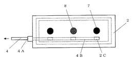
図1から図10は、本発明の実施形態1を示し、電池ケースは箱状で、上側ホルダ1と下側ホルダ2とが接合されてできており、上側ホルダ1には冷却液を流入させる流入部3を有し、下側ホルダ2には流路6から冷却液を流出させる流出部4を有し、電池ケースに収容される電池100は円筒形を例示する筒形のリチウムイオン電池などの二次電池で、正極の電極端子100Aおよび負極の電極端子100Bがそれぞれ上端および下端に設けられている。この場合、電極端子100Aおよび電極端子100Bはそれぞれ正極および負極を例示しているが、アルミニウム材の筒形のリチウムイオン電池においては、負極の電極端子100Aおよび正極の電極端子100Bであり、7および7Aはそれぞれ負極端子および負極端子接続部で、8、8Aおよび8Bはそれぞれ正極端子、正極端子接続部および電池接触負極板である。
(Embodiment 1)
FIG. 1 to FIG. 10 show Embodiment 1 of the present invention, in which a battery case is box-shaped and is formed by joining an upper holder 1 and a lower holder 2, and a coolant is allowed to flow into the upper holder 1. The inflow part 3 is provided, the lower holder 2 has the outflow part 4 for allowing the coolant to flow out from the flow path 6, and the battery 100 accommodated in the battery case is a cylindrical lithium ion battery, etc. In the secondary battery, a positive electrode terminal 100A and a negative electrode terminal 100B are provided at the upper end and the lower end, respectively. In this case, the electrode terminal 100A and the electrode terminal 100B illustrate the positive electrode and the negative electrode, respectively. However, in the cylindrical lithium ion battery made of aluminum, the electrode terminal 100A and the positive electrode terminal 100B are the negative electrode terminal 100A and the positive electrode terminal 100B. 7A is a negative electrode terminal and a negative electrode terminal connection part, respectively, 8, 8A and 8B are a positive electrode terminal, a positive electrode terminal connection part, and a battery contact negative electrode plate, respectively.

図1、図2および図4において、上側ホルダ1は、下端が開口した箱状で、上端壁1Aと筒状の周壁1Bとで空間部を形成し、この空間部には上端壁1Aの内面に複数個(図では3個)の筒状でその下端が開口した環状壁1Cが一直線状に形成されている。これら上端壁1A、周壁1Bおよび環状壁1Cは合成樹脂材で一体に形成されている。その合成樹脂材としては、ポリフェニレンサルファイド系樹脂、ポリエチレン系樹脂、ポリプロピレン系樹脂、ポリスチレン系樹脂、ポリカーボネート系樹脂、ポリ塩化ビニル系樹脂、ポリエチレンテレフタレート系樹脂、ポリブチレンテレフタレート系樹脂、ポリエチレンナフタレート系樹脂、ポリブチレンナフタレート系樹脂、フッ素系樹脂、ポリエーテルエーテルケトン系樹脂などの熱可塑性樹脂およびフェノール系樹脂やエポキシ系樹脂などの熱硬化性樹脂が例示できる。1, 2 and 4, the upper holder 1 has a box shape with an open lower end, and an upper end wall 1 </ b> A and a cylindrical peripheral wall 1 </ b> B form a space, and this space has an inner surface of the upper end wall 1 </ b> A. In addition, a plurality (three in the figure) of cylindrical walls 1 </ b> C having an open lower end are formed in a straight line. The upper end wall 1A, the peripheral wall 1B, and the annular wall 1C are integrally formed of a synthetic resin material. The synthetic resin material includes polyphenylene sulfide resin, polyethylene resin, polypropylene resin, polystyrene resin, polycarbonate resin, polyvinyl chloride resin, polyethylene terephthalate resin, polybutylene terephthalate resin, polyethylene naphthalate resin. Examples thereof include thermoplastic resins such as polybutylene naphthalate resins, fluorine resins, and polyether ether ketone resins, and thermosetting resins such as phenol resins and epoxy resins.

各筒状の環状壁1Cの内部には上下端が開口した筒状の電池収容室5が上端壁1Aと一体に形成されている。この電池収容室5の素材は、熱伝導性がよい素材で、例えばアルミニウム、銅、鉄などの金属材または前記金属材表面にニッケル膜形成などの表面処理をした金属材またはステンレスなどの金属材であり、合成樹脂材であれば、他の部位よりも薄肉とすることが好ましい。また、形状は、電池100を収容する大きさで、図においては、リチウムイオン電池などの二次電池で円筒形の電池を例示しているので、円筒状である。各電池収容室5と環状壁1Cとの間は流路形成空間部1Eとなり、上端壁1Aの後述する流入ガイド孔1Dから下端方向に螺旋状に延びる流路6が形成されている。流路6を螺旋状に形成する方法としては、フッ素系樹脂などの合成樹脂材やアルミニウムやステンレスなどの金属材を螺旋状に形成した螺旋状成形品をもちいて、図7に示すように電池収容室5の外周の流路形成空間部1Eに装着する方法を例示する。なお、この螺旋状の流路6の形成法においては、螺旋状成形品の装着ではなく、電池収容室5の外周に一体成形などで予め固着しておけば、螺旋状成形品の装着作業は不要となる。また、各電池収容室5の内部の上端面のほぼ中央の部位にはアルミニウムや銅などの金属材でできた正極端子接続部7Aまたは負極端子接続部8Aが形成されており、負極端子接続部8Aについては、電池収容室5の上端面の内面に電池接触負極板8Bが形成されているが、この電池接触負極板8Bは、上側ホルダ1の上端壁1Aの内面に形成してもよい。Inside each cylindrical annular wall 1C, a cylindrical battery housing chamber 5 having upper and lower ends opened is formed integrally with the upper end wall 1A. The material of the battery housing chamber 5 is a material having good thermal conductivity, such as a metal material such as aluminum, copper, or iron, or a metal material such as a nickel material formed on the surface of the metal material or a metal material such as stainless steel. If it is a synthetic resin material, it is preferable to make it thinner than other parts. Further, the shape is a size that accommodates the battery 100, and in the figure, a secondary battery such as a lithium ion battery is illustrated as a cylindrical battery, and thus the shape is cylindrical. Between each battery storage chamber 5 and the annular wall 1C is a flow path forming space portion 1E, and a flow path 6 that spirally extends in a lower end direction from an inflow guide hole 1D (described later) of the upper end wall 1A is formed. As a method of forming the channel 6 in a spiral shape, a synthetic resin material such as a fluorine-based resin or a spiral molded product in which a metal material such as aluminum or stainless steel is spirally formed is used, as shown in FIG. The method of mounting | wearing with the flow-path formation space part 1E of the outer periphery of the storage chamber 5 is illustrated. In this method of forming the spiral flow path 6, if the spiral molded product is not fixed to the outer periphery of the battery storage chamber 5, but is fixed in advance by integral molding or the like, the mounting operation of the spiral molded product is not necessary. It becomes unnecessary. Further, a positive terminal connecting portion 7A or a negative terminal connecting portion 8A made of a metal material such as aluminum or copper is formed at a substantially central portion of the upper end surface inside each battery housing chamber 5, and the negative terminal connecting portion is formed. As for 8A, the battery contact negative electrode plate 8B is formed on the inner surface of the upper end surface of the battery housing chamber 5. However, this battery contact negative electrode plate 8B may be formed on the inner surface of the upper end wall 1A of the upper holder 1.

また、上端壁1Aには、冷却液を流路6に流入させる流入部3が形成されている。この流入部3は、流入口3Aと流入路3Bとからなり、流入口3Aは流入路3Bに連通して上端壁1Aで周壁1Bの外方向に突出して形成されており、流入路3Bは、合成樹脂材の上端壁1Aに埋設するように一体に成形可能な金属材でできた中空管で、複数個の流入孔3Cが形成されて各流路6に冷却液を流入させるように形成されている。この流入孔3Cの部位には、図10に示すように、流入路3Bの内壁面が部分的に突出されるように流入路3Bを局所的に狭窄する絞り部3Dが形成されることにより、冷却液を各流路6に導いて流入しやすくしている。In addition, an inflow portion 3 for allowing the coolant to flow into the flow path 6 is formed in the upper end wall 1A. The inflow portion 3 includes an inflow port 3A and an inflow channel 3B. The inflow port 3A communicates with the inflow channel 3B and is formed to protrude outward from the peripheral wall 1B at the upper end wall 1A. A hollow tube made of a metal material that can be integrally molded so as to be embedded in the upper end wall 1A of a synthetic resin material. A plurality of inflow holes 3C are formed so that a coolant flows into each flow path 6. Has been. As shown in FIG. 10, the inflow hole 3 </ b> C is formed with a throttle portion 3 </ b> D that locally narrows the inflow path 3 </ b> B so that the inner wall surface of the inflow path 3 </ b> B is partially projected. The cooling liquid is guided to each flow path 6 so as to easily flow in.

さらに、上端壁1Aにおいて各電池収容室5の上端面側のほぼ中央の部位に形成された正極端子接続部7Aおよび負極端子接続部8Aのそれぞれに接続された電池100の電極端子である正極端子7および負極端子8が図4に示すように、並設されている。この場合、負極端子8については、電池接触負極板8Bを介して負極端子接続部8Aに接続されている。また、上端壁1Aで中央の部位から離れた部位、すなわち、正極端子7および負極端子8から離れた部位には、流入路3Bの流入孔3Cと連通した流入ガイド孔1Dが形成されている。従って、冷却液は、電池収容室5の外周に流入されており、電池収容室5の内部には流入されないので、電池100の電極端子が冷却液と接触しないようにすることができる。Furthermore, the positive electrode terminal which is an electrode terminal of the battery 100 connected to each of the positive electrode terminal connecting portion 7A and the negative electrode terminal connecting portion 8A formed at the substantially central portion on the upper end surface side of each battery accommodating chamber 5 in the upper end wall 1A. 7 and the negative electrode terminal 8 are juxtaposed as shown in FIG. In this case, the negative electrode terminal 8 is connected to the negative electrode terminal connection portion 8A via the battery contact negative electrode plate 8B. Further, an inflow guide hole 1D communicating with the inflow hole 3C of the inflow passage 3B is formed in a portion away from the central portion of the upper end wall 1A, that is, a portion away from the positive electrode terminal 7 and the negative electrode terminal 8. Therefore, the coolant flows into the outer periphery of the battery housing chamber 5 and does not flow into the battery housing chamber 5, so that the electrode terminals of the battery 100 can be prevented from coming into contact with the coolant.

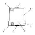
一方、図1、図2および図5において、下側ホルダ2は、上端が開口した箱状で、上側ホルダ1に接合して、上側ホルダ1の下端の開口を閉塞させるように、下端壁2Aと筒状の周壁2Bとで空間部を有し、これら下端壁2Aおよび周壁2Bは合成樹脂材でできており、その素材は上側ホルダ1の上端壁1A、周壁1Bおよび環状壁1Cと同じ素材が例示できる。下端壁2Aのほぼ中央の部位には、正極端子接続部7Aおよび負極端子接続部8Aに接続された電池100の電極端子である正極端子7および負極端子8が図5に示すように設けられており、正極端子7および負極端子8はそれぞれ上端壁1Aの正極端子7および負極端子8と正極および負極の対になるように並設されている。この場合、負極端子8については、下端壁2Aの上面(上側ホルダ1の電池収容室5に対面する面)に形成された電池接触負極板8Bを介して負極端子接続部8Aに接続されている。また、下端壁2Aには、中央の部位から離れた部位、すなわち、これら正極端子7および負極端子8から離れた部位には、複数個の流出ガイド孔2Cが形成されている。On the other hand, in FIG. 1, FIG. 2 and FIG. 5, the lower holder 2 has a box shape with the upper end opened, and is joined to the upper holder 1 so as to close the lower end opening of the upper holder 1. And the cylindrical peripheral wall 2B have a space, the lower end wall 2A and the peripheral wall 2B are made of a synthetic resin material, and the material thereof is the same material as the upper end wall 1A, the peripheral wall 1B and the annular wall 1C of the upper holder 1 Can be illustrated. As shown in FIG. 5, a positive electrode terminal 7 and a negative electrode terminal 8 which are electrode terminals of the battery 100 connected to the positive electrode terminal connection portion 7A and the negative electrode terminal connection portion 8A are provided at a substantially central portion of the lower end wall 2A. The positive electrode terminal 7 and the negative electrode terminal 8 are arranged in parallel so as to be a pair of the positive electrode terminal 7 and the negative electrode terminal 8 of the upper end wall 1A and the positive electrode and the negative electrode, respectively. In this case, the negative electrode terminal 8 is connected to the negative electrode terminal connection portion 8A via the battery contact negative electrode plate 8B formed on the upper surface of the lower end wall 2A (the surface facing the battery storage chamber 5 of the upper holder 1). . In the lower end wall 2A, a plurality of outflow guide holes 2C are formed in portions away from the central portion, that is, in portions away from the positive terminal 7 and the negative terminal 8.

さらに、下端壁2Aには、中央の部位から離れた部位、すなわち、正極端子7および負極端子8から離れた部位には、冷却液を流路6から流出させる流出部4が形成されている。この流出部4は、流出路4Bと、この流出路4Bと連通した周壁2Bの外方向に突出した流出口4Aとからなる。この流出路4Bは、合成樹脂材の下端壁2Aに埋設するように一体に成形可能な金属材でできた中空管で、各流路6から冷却液を流出させるように流出ガイド孔2Cと連通した流出孔4Cが形成されている。従って、冷却液は、電池収容室5の内部に流出入されないので、冷却液が電池100の正極の電極端子100Aおよび負極の電極端子100Bに接触しないようにすることができる。Furthermore, the lower end wall 2 </ b> A is formed with an outflow portion 4 for allowing the coolant to flow out of the flow path 6 at a portion away from the central portion, that is, a portion away from the positive terminal 7 and the negative terminal 8. The outflow portion 4 includes an outflow passage 4B and an outflow port 4A protruding outward from the peripheral wall 2B communicating with the outflow passage 4B. The outflow passage 4B is a hollow tube made of a metal material that can be integrally molded so as to be embedded in the lower end wall 2A of the synthetic resin material, and the outflow guide hole 2C and the outflow guide hole 2C A communicating outflow hole 4C is formed. Accordingly, since the coolant does not flow into and out of the battery housing chamber 5, the coolant can be prevented from contacting the positive electrode terminal 100A and the negative electrode terminal 100B of the battery 100.

次に、図7から図9を参照して、上側ホルダ1と下側ホルダ2とを接合して電池ケースを形成する手順を以下、説明する。Next, a procedure for joining the upper holder 1 and the lower holder 2 to form a battery case will be described below with reference to FIGS.

先ず、下端が開口した箱状で、上端壁1Aと筒状の周壁1Bとで空間部を有し、この空間部において複数個の筒状の環状壁1Cが直線状に配列するようにした形状の成形型を用意し、この成形型に合成樹脂材を充填するに際し、矢印A方向に複数個の筒状の電池収容室5、中空管状の流入路3B、正極端子接続部7Aおよび負極端子接続部8Aの金属材をインサートして射出成形して環状壁1Cと電池収容室5との間の流路形成空間部1Eを形成する。この場合、複数個の筒状の電池収容室5の一部、図では3個のうち、1番目および3番目には正極端子接続部7Aが形成されており、2番目(真中)には電池接触負極板8Bを介して負極端子接続部8Aが形成されている。また、これら正極端子接続部7Aおよび負極端子接続部8Aから離れた部位に流入ガイド孔1Dが形成されており、この流入ガイド孔1Dに連通して流入孔3Cを有する流入路3Bが上端壁1Aに埋設されている。次に、この流路形成空間部1Eに螺旋状に形成した螺旋状成形品を矢印B方向に挿入して筒状の電池収容室5の外周に装着することにより、上側ホルダ1が形成される。一方、下側ホルダ2においても、上端が開口した箱状で、下端壁2Aと筒状の周壁2Bとで空間部を有する形状の成形型に合成樹脂材を充填するに際し、矢印A方向に中空管状の流出路4B、正極端子接続部7Aおよび負極端子接続部8Aの金属材をインサートして射出成形して上側ホルダ1の3個の筒状の電池収容室5と対応してその1番目および3番目に電池接触負極板8Bを形成して下側ホルダ2が形成される。このようにして上側ホルダ1と下側ホルダ2とを用意して、この上側ホルダ1の電池収容室5に電池100を1番目および3番目においては正極が上方で、2番目(真中)においては正極が下方となるようにして矢印C方向に挿入させて後、下側ホルダ2の開口した上端を上側ホルダ1の開口した下端に矢印D方向に重合するようにして接着剤などで接合することにより、螺旋状の流路6を有し複数個の電池100が密閉して収容され電池ケースが得られる。この場合、電池100を交換するために電池100を着脱できるように、上側ホルダ1と下側ホルダ2との接合を接着剤や溶着などではなく取り外し可能なバンドなどをもちいてもよい。First, a box-like shape having an open lower end has a space portion between an upper end wall 1A and a cylindrical peripheral wall 1B, and a plurality of cylindrical annular walls 1C are linearly arranged in this space portion. When the mold is filled with a synthetic resin material, a plurality of cylindrical battery housing chambers 5, hollow tubular inflow passages 3B, positive terminal connecting portions 7A and negative terminal connecting in the direction of arrow A are prepared. The metal material of the part 8A is inserted and injection-molded to form a flow path forming space 1E between the annular wall 1C and the battery housing chamber 5. In this case, a positive terminal connection portion 7A is formed in the first and third of a part of the plurality of cylindrical battery housing chambers 5, three in the figure, and the second (middle) battery. A negative electrode terminal connection portion 8A is formed through the contact negative electrode plate 8B. Further, an inflow guide hole 1D is formed in a portion away from the positive electrode terminal connection portion 7A and the negative electrode terminal connection portion 8A, and an inflow passage 3B having an inflow hole 3C communicating with the inflow guide hole 1D is formed in the upper end wall 1A. It is buried in. Next, the upper holder 1 is formed by inserting a spiral molded product formed in a spiral shape in the flow path forming space 1E in the direction of the arrow B and mounting it on the outer periphery of the cylindrical battery housing chamber 5. . On the other hand, the lower holder 2 is hollow in the direction of arrow A when filling a molding die having a box shape with an upper end opened and having a space portion between the lower end wall 2A and the cylindrical peripheral wall 2B. The metal material of the tubular outflow passage 4B, the positive terminal connecting portion 7A and the negative terminal connecting portion 8A is inserted and injection-molded to correspond to the three cylindrical battery housing chambers 5 of the upper holder 1, and the first and Third, the battery contact negative electrode plate 8B is formed, and the lower holder 2 is formed. Thus, the upper holder 1 and the lower holder 2 are prepared, and the battery 100 is placed in the battery storage chamber 5 of the upper holder 1 in the first and third, the positive electrode is upward, and in the second (middle). After the positive electrode is inserted in the direction of arrow C with the positive electrode facing down, the upper end of the lower holder 2 opened is joined to the opened lower end of the upper holder 1 with an adhesive or the like so as to overlap in the direction of arrow D Thus, a battery case having a spiral flow path 6 and a plurality of batteries 100 sealed and housed is obtained. In this case, in order to replace the battery 100 in order to replace the battery 100, the upper holder 1 and the lower holder 2 may be joined using a removable band instead of an adhesive or welding.

次に、図1および図2を参照して、電池100を冷却する冷却液の流れ動作を以下、説明する。Next, with reference to FIG. 1 and FIG. 2, the flow operation of the cooling liquid for cooling the battery 100 will be described below.

冷却液については、冷却水を例示しており、この冷却液が流入部3の流入口3Aから上側ホルダ1の流入路3Bに流入されると、流入された冷却液は流入路3Bに形成された流入孔3C(図10参照)から流入ガイド孔1Dを経て各電池収容室5の流路形成空間部1Eにある螺旋状の流路6に流入されて、冷却液は螺旋状に流れて、下側ホルダ2の流出ガイド孔2Cから流出部4の流出孔4Cを経て流出路4Bに流れて流出口4Aから排出される。このような流入部3から流路6を経て流出部4に流れる冷却液は冷却液供給装置(図示せず)で循環され、冷却液は螺旋状の流路6により、各電池収容室5の外周に相当する流路形成空間部1Eに滞留することなく円滑に流れて各電池100が電池収容室5を介して効率よく冷却される。As for the cooling liquid, cooling water is illustrated, and when this cooling liquid flows into the inflow path 3B of the upper holder 1 from the inflow port 3A of the inflow portion 3, the inflowing cooling liquid is formed in the inflow path 3B. The inflow hole 3C (see FIG. 10) flows into the spiral flow path 6 in the flow path forming space 1E of each battery storage chamber 5 through the inflow guide hole 1D, and the coolant flows spirally. It flows from the outflow guide hole 2C of the lower holder 2 through the outflow hole 4C of the outflow portion 4 to the outflow passage 4B and is discharged from the outflow port 4A. The cooling liquid flowing from the inflow part 3 to the outflow part 4 through the flow path 6 is circulated by a cooling liquid supply device (not shown), and the cooling liquid is stored in each battery storage chamber 5 by the spiral flow path 6. The batteries 100 flow smoothly without staying in the flow path forming space 1 </ b> E corresponding to the outer periphery, and each battery 100 is efficiently cooled via the battery housing chamber 5.

(実施形態2)
図11から図16は、本発明の実施形態2を示し、実施形態1と同様に電池ケースは箱状で、上側ホルダ1と下側ホルダ2とが接合されてできており、上側ホルダ1には冷却液を流路6に流入させる流入部3を有し、下側ホルダ2には流路6から冷却液を流出させる流出部4を有し、電池ケースに収容される電池101は実施形態1と異なり、長円筒形を例示する筒形のリチウムイオン電池などの二次電池で、正極の電極端子101Aおよび負極の電極端子101Bが上端に並設されている。
(Embodiment 2)
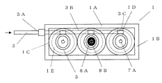
FIGS. 11 to 16 show a second embodiment of the present invention. Like the first embodiment, the battery case has a box shape, and the upper holder 1 and the lower holder 2 are joined. Has an inflow part 3 for allowing cooling liquid to flow into the flow path 6, and the lower holder 2 has an outflow part 4 for allowing cooling liquid to flow out of the flow path 6, and the battery 101 accommodated in the battery case is an embodiment. 1, in a secondary battery such as a cylindrical lithium ion battery exemplifying a long cylindrical shape, a positive electrode terminal 101 </ b> A and a negative electrode terminal 101 </ b> B are arranged in parallel at the upper end.

上側ホルダ1は、下端が開口した箱状で、上端壁1Aと筒状の周壁1Bとで空間部を形成し、この空間部には上端壁1Aの内面に複数個(図では3個)の筒状でその下端が開口した環状壁1Cが一直線状に形成されている。これら上端壁1A、周壁1Bおよび環状壁1Cは合成樹脂材で一体に形成されている。その合成樹脂材としては、ポリフェニレンサルファイド系樹脂、ポリエチレン系樹脂、ポリプロピレン系樹脂、ポリスチレン系樹脂、ポリカーボネート系樹脂、ポリ塩化ビニル系樹脂、ポリエチレンテレフタレート系樹脂、ポリブチレンテレフタレート系樹脂、ポリエチレンナフタレート系樹脂、ポリブチレンナフタレート系樹脂、フッ素系樹脂、ポリエーテルエーテルケトン系樹脂などの熱可塑性樹脂およびフェノール系樹脂やエポキシ系樹脂などの熱硬化性樹脂が例示できる。The upper holder 1 has a box shape with an open lower end, and an upper end wall 1A and a cylindrical peripheral wall 1B form a space portion. A plurality of (three in the figure) inner surfaces of the upper end wall 1A are formed in the space portion. An annular wall 1C that is cylindrical and has an open lower end is formed in a straight line. The upper end wall 1A, the peripheral wall 1B, and the annular wall 1C are integrally formed of a synthetic resin material. The synthetic resin material includes polyphenylene sulfide resin, polyethylene resin, polypropylene resin, polystyrene resin, polycarbonate resin, polyvinyl chloride resin, polyethylene terephthalate resin, polybutylene terephthalate resin, polyethylene naphthalate resin. Examples thereof include thermoplastic resins such as polybutylene naphthalate resins, fluorine resins, and polyether ether ketone resins, and thermosetting resins such as phenol resins and epoxy resins.

各筒状の環状壁1Cの内部には筒状の電池収容室5が上端壁1Aと一体に形成されている。この電池収容室5の素材は、実施形態1と同様に熱伝導性がよい素材で、例えばアルミニウム、銅、鉄などの金属材または前記金属材表面にニッケル膜形成などの表面処理をした金属材またはステンレスなどの金属材であり、また、形状は、電池101を収容する大きさで、図においては、長円筒形の電池を例示しているので、長円筒状で、上端壁1Aと一体に成形されている。電池収容室5の外周において、環状壁1Cとの間の流路形成空間部1Eには下端方向に螺旋状に延びる流路6が形成されている。流路6を螺旋状に形成するには、実施形態1と同様な方法で、例えば、フッ素系樹脂などの合成樹脂材やアルミニウムやステンレスなどの金属材を螺旋状に形成した螺旋状成形品を電池収容室5の外周の流路形成空間部1Eに装着すればよい。また、上端壁1A、周壁1Bおよび環状壁1Cを合成樹脂材とし、金属材の電池収容室5と一体に成形するに際し、図16に示すように、上端壁1Aに電池収容室5と連通した一対の端子貫挿孔1F、1Fを成形型で形成させる。その結果、電池101を電池収容室5に収容する際に、図11に示すように各電池収容室5の上端面の部位の端子貫挿孔1F、1Fのそれぞれに電池101の正極の電極端子101Aおよび負極の電極端子101Bを貫挿して上端壁1Aの外部に突出させ、ボルト締めなどで接続固定されてそれぞれ正極端子9および負極端子10を形成する。A cylindrical battery housing chamber 5 is formed integrally with the upper end wall 1A inside each cylindrical annular wall 1C. The material of the battery housing chamber 5 is a material having good thermal conductivity as in the first embodiment. For example, a metal material such as aluminum, copper, or iron, or a metal material that has been surface-treated such as forming a nickel film on the surface of the metal material Or it is metal materials, such as stainless steel, and the shape is the magnitude | size which accommodates the battery 101, and in the figure, since the long cylindrical battery is illustrated, it is long cylindrical shape and is integrated with 1 A of upper end walls. Molded. On the outer periphery of the battery housing chamber 5, a flow path 6 that spirally extends in the lower end direction is formed in the flow path forming space 1E between the annular wall 1C. In order to form the flow path 6 in a spiral shape, for example, a spiral molded product in which a synthetic resin material such as a fluorine-based resin or a metal material such as aluminum or stainless steel is formed in a spiral shape is used. What is necessary is just to mount | wear with the flow-path formation space part 1E of the outer periphery of the battery storage chamber 5. FIG. Further, when the upper end wall 1A, the peripheral wall 1B and the annular wall 1C are made of a synthetic resin material and are integrally formed with the battery housing chamber 5 made of a metal material, the upper end wall 1A communicates with the battery housing chamber 5 as shown in FIG. A pair of terminal penetration holes 1F and 1F are formed with a mold. As a result, when the battery 101 is housed in the battery housing chamber 5, as shown in FIG. 11, the electrode terminal of the positive electrode of the battery 101 is inserted into each of the terminal insertion holes 1F and 1F on the upper end surface of each battery housing chamber 5. The positive electrode terminal 9 and the negative electrode terminal 10 are formed by inserting 101A and the negative electrode terminal 101B so as to protrude outside the upper end wall 1A and being connected and fixed by bolting or the like.

さらに、上端壁1Aには、ほぼ中央の部位で端子貫挿孔1F、1Fの間、すなわち、正極端子9と負極端子10との間に冷却液を流路6に流入させる流入部3が形成されている。この流入部3は、流入路3Bと流入口3Aとからなり、流入口3Aは流入路3Bに連通して上端壁1Aで周壁1Bの外方向に突出して形成されている。この流入路3Bは、合成樹脂材の上端壁1Aに埋設するように一体に成形可能な金属材でできた中空管でできている。この場合、流入路3Bを合成樹脂材の上端壁1Aに埋設するには、上端壁1Aと筒状の周壁1Bとで空間部を有し、この空間部において複数個の筒状の環状壁1Cが直線状に配列するようにした形状の成形型を用意し、この成形型に合成樹脂材を充填するに際し、複数個の筒状の電池収容室5および中空管状の流入路3Bの金属材をインサートして射出成形して得られる。また、流入路3Bは、実施形態1と同様で図10に示すように、複数個の流入孔3Cが形成されて各流路6に冷却液を流入させるようにしている。流入孔3Cの部位には流入路3Bの内壁面が部分的に突出されるように流入路3Bを局所的に狭窄する絞り部3Dが形成されることにより、冷却液を流路6に流入しやすくして、この流入路3Bの流入孔3Cと連通した流入ガイド孔1Dが上端壁1Aで各電池収容室5の上端面の部位に形成されている。従って、冷却液は、電池収容室5の内部に流入されないので、電池101の正極の電極端子101Aおよび負極の電極端子101Bが冷却液と接触しないようにすることができる。Further, the upper end wall 1A is formed with an inflow portion 3 for allowing the coolant to flow into the flow path 6 between the terminal insertion holes 1F and 1F, that is, between the positive electrode terminal 9 and the negative electrode terminal 10 at a substantially central portion. Has been. The inflow portion 3 includes an inflow passage 3B and an inflow port 3A. The inflow port 3A communicates with the inflow passage 3B and is formed to protrude outward from the peripheral wall 1B at the upper end wall 1A. This inflow passage 3B is made of a hollow tube made of a metal material that can be integrally molded so as to be embedded in the upper end wall 1A of a synthetic resin material. In this case, in order to embed the inflow passage 3B in the upper end wall 1A of the synthetic resin material, the upper end wall 1A and the cylindrical peripheral wall 1B have a space portion, and a plurality of cylindrical annular walls 1C are provided in the space portion. Are prepared in a straight line, and when filling the mold with a synthetic resin material, a plurality of cylindrical battery housing chambers 5 and metal materials of the hollow tubular inflow passages 3B are prepared. It is obtained by inserting and injection molding. Further, the inflow path 3B is the same as in the first embodiment, and as shown in FIG. 10, a plurality of inflow holes 3C are formed so that the coolant flows into each flow path 6. In the portion of the inflow hole 3C, a constricted portion 3D that locally narrows the inflow passage 3B is formed so that the inner wall surface of the inflow passage 3B protrudes partially, so that the coolant flows into the flow passage 6. For ease of explanation, an inflow guide hole 1D communicating with the inflow hole 3C of the inflow path 3B is formed at the upper end wall 1A at a portion of the upper end surface of each battery housing chamber 5. Therefore, since the coolant does not flow into the battery housing chamber 5, the positive electrode terminal 101A and the negative electrode terminal 101B of the battery 101 can be prevented from coming into contact with the coolant.

一方、下側ホルダ2は、上端が開口した箱状で、上側ホルダ1に接合して、上側ホルダ1の下端の開口を閉塞させるように、下端壁2Aと筒状の周壁2Bとで空間部を有し、これら下端壁2Aおよび周壁2Bは合成樹脂材でできており、その素材は上側ホルダ1の上端壁1A、周壁1Bおよび環状壁1Cと同じ素材が例示できる。下端壁2Aのほぼ中央の部位には、複数個の流出ガイド孔2Cおよび冷却液を流路6から流出させる流出部4が形成されている。この流出部4は、流出路4Bと、この流出路4Bと連通した周壁2Bの外方向に突出した流出口4Aとからなる。流出路4Bは、合成樹脂材の下端壁2Aに埋設するように一体に成形可能な金属材でできた中空管でできている。この場合、流出路4Bを合成樹脂材の下端壁2Aに埋設するには、下端壁2Aと筒状の周壁2Bとで空間部を有する形状の成形型に合成樹脂材を充填するに際し、中空管状の流出路4Bの金属材をインサートして射出成形して得られる。流出路4Bには、各流路6から冷却液を流出させるように流出ガイド孔2Cと連通した流出孔4Cが形成されている。従って、冷却液は、電池収容室5の内部に流出入されないので、電池101の正極の電極端子101Aおよび負極の電極端子101Bが冷却液と接触しないようにすることができる。On the other hand, the lower holder 2 has a box shape with an upper end opened, and is joined to the upper holder 1 so as to close the opening at the lower end of the upper holder 1 with the lower end wall 2A and the cylindrical peripheral wall 2B. The lower end wall 2A and the peripheral wall 2B are made of a synthetic resin material, and the same material as the upper end wall 1A, the peripheral wall 1B and the annular wall 1C of the upper holder 1 can be exemplified. A plurality of outflow guide holes 2C and an outflow portion 4 through which the coolant flows out from the flow path 6 are formed at a substantially central portion of the lower end wall 2A. The outflow portion 4 includes an outflow passage 4B and an outflow port 4A protruding outward from the peripheral wall 2B communicating with the outflow passage 4B. The outflow passage 4B is made of a hollow tube made of a metal material that can be integrally molded so as to be embedded in the lower end wall 2A of the synthetic resin material. In this case, in order to embed the outflow passage 4B in the lower end wall 2A of the synthetic resin material, when filling the molding die having a space portion with the lower end wall 2A and the cylindrical peripheral wall 2B, The metal material of the outflow passage 4B is inserted and obtained by injection molding. The outflow path 4B is formed with an outflow hole 4C communicating with the outflow guide hole 2C so as to allow the coolant to flow out from the respective flow paths 6. Therefore, since the coolant does not flow into and out of the battery housing chamber 5, the positive electrode terminal 101A and the negative electrode terminal 101B of the battery 101 can be prevented from coming into contact with the coolant.

上側ホルダ1と下側ホルダ2とにおいて、下側ホルダ2の開口した上端を上側ホルダ1の開口した下端に重合するようにして実施形態1と同様に接着剤やバンドなどで接合することにより、上側ホルダ1の下端の開口を閉塞させるようにして、螺旋状の流路6を有し複数個の電池101を収容した電池ケースが得られ、冷却水を例示する冷却液が流入部3の流入口3Aから上側ホルダ1の流入路3Bに流入されると、流入された冷却液は流入路3Bに形成された流入孔3C(図10参照)から流入ガイド孔1Dを経て各電池収容室5の流路形成空間部1Eにある螺旋状の流路6にて冷却液は螺旋状に流れて下側ホルダ2の流出ガイド孔2Cから流出部4の流出孔4Cを経て流出路4Bに流れて流出口4Aから排出される。その際、流入部3および流出部4は冷却液供給装置(図示せず)で循環されて、各電池収容室5を介して各電池101を効率よく冷却することができる。In the upper holder 1 and the lower holder 2, the upper end opened of the lower holder 2 is joined to the opened lower end of the upper holder 1 by joining with an adhesive or a band as in the first embodiment, A battery case having a spiral flow path 6 and containing a plurality of batteries 101 is obtained so as to close the opening at the lower end of the upper holder 1, and the cooling liquid exemplifies cooling water flows through the inflow portion 3. When flowing into the inflow path 3B of the upper holder 1 from the inlet 3A, the inflowing coolant flows from the inflow holes 3C (see FIG. 10) formed in the inflow path 3B through the inflow guide holes 1D to the respective battery accommodating chambers 5. The coolant flows spirally in the spiral flow path 6 in the flow path forming space 1E, flows from the outflow guide hole 2C of the lower holder 2 to the outflow path 4B through the outflow hole 4C of the outflow section 4. It is discharged from the outlet 4A. At that time, the inflow portion 3 and the outflow portion 4 are circulated by a coolant supply device (not shown), and each battery 101 can be efficiently cooled via each battery housing chamber 5.

(実施形態3)
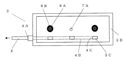
図17から図21は、本発明の実施形態3を示し、電池ケースは箱状で、上側ホルダ1と下側ホルダ2とが接合されてできており、上側ホルダ1には冷却液を流入させる流入部3および冷却液を流出させる流出部4とを有し、電池ケースに収容される電池100は実施形態1と同じ円筒形を例示する筒形のリチウムイオン電池などの二次電池で、正極の電極端子100Aおよび負極の電極端子100Bがそれぞれ上端および下端に設けられているが、流入部3および流出部4の部位が実施形態1と異なり、以下、説明する。
(Embodiment 3)
FIGS. 17 to 21 show Embodiment 3 of the present invention, in which the battery case is box-shaped, and is formed by joining the upper holder 1 and the lower holder 2, and the coolant is allowed to flow into the upper holder 1. A battery 100 having an inflow part 3 and an outflow part 4 for allowing cooling liquid to flow out and accommodated in the battery case is a secondary battery such as a cylindrical lithium ion battery, which is exemplified by the same cylindrical shape as that of the first embodiment, and is a positive electrode. The electrode terminal 100A and the negative electrode terminal 100B are provided at the upper end and the lower end, respectively, but the portions of the inflow portion 3 and the outflow portion 4 are different from those of the first embodiment and will be described below.

図17、図18および図19はそれぞれ冷却装置の正面図、側面図および平面であり、上側ホルダ1には、流入部3および流出部4が形成されており、実施形態1とは異なり、下側ホルダ2には流出部4が形成されていない。図20および図21は、それぞれ冷却装置の側面部位の断面図および正面部位の断面図であり、上側ホルダ1は下端が開口した箱状で、その素材は、実施形態1と同じ合成樹脂材でできており、上端壁1Aと筒状の周壁1Bとで空間部を形成し、この空間部には上端壁1Aの内面に複数個(例えば3個)の筒状でその下端が開口した環状壁1Cが一直線状に形成されている。各筒状の環状壁1Cの内部には上下端が開口した筒状の電池収容室5が実施形態1と同様な素材および形状で上端壁1Aと一体に形成されており、各電池収容室5と環状壁1Cとの間は流路形成空間部1Eとなる。上側ホルダ1には、実施形態1と異なり、流入路3Bおよび流出路4Bが設けられている。周壁1Bおよび環状壁1Cとの間には貫通孔でできた注入路1Hが形成されており、この注入路1Hは、上端が上側ホルダ1の流入ガイド孔1Dと連通して下側ホルダ2の方向に延び、下端が下側ホルダ2で閉塞されている。さらに、この注入路1Hの下端には流路形成空間部1Eと連通した孔部1Jが形成されている。この流路形成空間部1Eには実施形態1と同様な螺旋状成形品でできた流路6が形成されており、この螺旋状成形品の螺旋形状は実施形態1とは逆方向で上側方向に延びて、孔部1Jから流入された冷却液が下側ホルダ2の方向から上側ホルダ1の方向に流れて流出ガイド孔1Gから流出されるように形成されている。また、各電池収容室5の内部の上端面のほぼ中央の部位にはアルミニウムや銅などの金属材でできた正極端子接続部7Aまたは負極端子接続部8Aが形成されている。そのうち、負極端子接続部8Aについては、電池収容室5の上端面の内面に電池接触負極板8Bが形成されている。従って、流入路3Bおよび流出路4Bは上端壁1Aにおいて正極端子7および負極端子8から離れた部位に形成されている。なお、電極端子100Aおよび電極端子100Bはそれぞれ正極および負極を例示しているが、アルミニウム材の筒形のリチウムイオン電池においては、負極の電極端子100Aおよび正極の電極端子100Bである。FIGS. 17, 18 and 19 are a front view, a side view and a plan view of the cooling device, respectively, and the upper holder 1 is formed with an inflow portion 3 and an outflow portion 4. The side holder 2 is not formed with the outflow portion 4. 20 and 21 are a cross-sectional view of a side portion and a front portion of a cooling device, respectively, and the upper holder 1 is a box shape with an open lower end, and the material thereof is the same synthetic resin material as in the first embodiment. An upper end wall 1A and a cylindrical peripheral wall 1B form a space portion, and this space portion has an annular wall having a plurality of (for example, three) cylindrical openings on the inner surface of the upper end wall 1A. 1C is formed in a straight line. In each cylindrical annular wall 1C, a cylindrical battery housing chamber 5 with upper and lower ends opened is formed integrally with the upper end wall 1A with the same material and shape as in the first embodiment. And the annular wall 1C is a flow path forming space 1E. Unlike the first embodiment, the upper holder 1 is provided with an inflow path 3B and an outflow path 4B. An injection path 1H made of a through hole is formed between the peripheral wall 1B and the annular wall 1C. The injection path 1H communicates with the inflow guide hole 1D of the upper holder 1 at the upper end of the lower holder 2. The lower end is closed by the lower holder 2. Further, a hole 1J communicating with the flow path forming space 1E is formed at the lower end of the injection path 1H. A flow path 6 made of a spiral molded product similar to that of the first embodiment is formed in the flow path forming space 1E, and the spiral shape of the spiral molded product is opposite to that of the first embodiment in the upward direction. The coolant flowing in from the hole 1J flows from the direction of the lower holder 2 to the direction of the upper holder 1 and flows out of the outflow guide hole 1G. In addition, a positive terminal connecting portion 7A or a negative terminal connecting portion 8A made of a metal material such as aluminum or copper is formed at a substantially central portion of the upper end surface inside each battery housing chamber 5. Among them, for the negative electrode terminal connection portion 8 </ b> A, a battery contact negative electrode plate 8 </ b> B is formed on the inner surface of the upper end surface of the battery housing chamber 5. Therefore, the inflow path 3B and the outflow path 4B are formed in a portion away from the positive terminal 7 and the negative terminal 8 in the upper end wall 1A. The electrode terminal 100A and the electrode terminal 100B exemplify a positive electrode and a negative electrode, respectively. However, in a cylindrical lithium ion battery made of aluminum, the electrode terminal 100A and the electrode terminal 100B are a negative electrode terminal.

一方、下側ホルダ2は、上端が開口した箱状で、上側ホルダ1に接合して、上側ホルダ1の下端の開口を閉塞させるように、下端壁2Aと筒状の周壁2Bとで空間部を有し、これら下端壁2Aおよび周壁2Bは合成樹脂材でできており、その素材は上側ホルダ1の上端壁1A、周壁1Bおよび環状壁1Cと同じ素材が例示できる。下端壁2Aの部位には、正極端子接続部7Aおよび負極端子接続部8Aに接続された電池100の電極端子である正極端子7および負極端子8が設けられており、正極端子7および負極端子8はそれぞれ上端壁1Aの正極端子7および負極端子8と正極および負極の対になるように並設されている。この場合、負極端子8は、下端壁2Aの上面(上側ホルダ1の電池収容室5に対面する面)に形成された電池接触負極板8Bを介して負極端子接続部8Aに接続されている。On the other hand, the lower holder 2 has a box shape with an upper end opened, and is joined to the upper holder 1 so as to close the opening at the lower end of the upper holder 1 with the lower end wall 2A and the cylindrical peripheral wall 2B. The lower end wall 2A and the peripheral wall 2B are made of a synthetic resin material, and the same material as the upper end wall 1A, the peripheral wall 1B and the annular wall 1C of the upper holder 1 can be exemplified. The positive electrode terminal 7 and the negative electrode terminal 8 which are electrode terminals of the battery 100 connected to the positive electrode terminal connection portion 7A and the negative electrode terminal connection portion 8A are provided at the lower end wall 2A. Are arranged side by side so as to be a pair of a positive electrode terminal and a negative electrode terminal 8 of the upper end wall 1A and a positive electrode and a negative electrode. In this case, the negative electrode terminal 8 is connected to the negative electrode terminal connection portion 8A via a battery contact negative electrode plate 8B formed on the upper surface of the lower end wall 2A (the surface facing the battery storage chamber 5 of the upper holder 1).

このように形成された上側ホルダ1と下側ホルダ2とを実施形態1と同様に接着剤や溶着または取り外し可能なバンドなどで接合することにより、螺旋状の流路6を有し複数個の電池100が収容された電池ケースが得られ、冷却液が流入ガイド孔1Dから注入路1Hに流れ、孔部1Jから矢印で示すように流路6に流入し、流出ガイド孔1Gに流出することにより、この流路6は螺旋状であるので、冷却液が滞留することなく円滑に流れて、各電池収容室5を介して各電池100を効率よく冷却することができる。しかも、冷却液が各電池収容室5の内部に流出入しないので、各電池の電極端子100A、100Bが冷却液と接触しないようにすることができ、さらに、流入路3Bおよび流出路4Bは上側ホルダ1に並設されているので、下側ホルダ2に流出路4Bを設けるスペースを必要とせず、コンパクトな冷却装置を提供することができる。The upper holder 1 and the lower holder 2 formed as described above are joined together with an adhesive, a welded band, or a removable band in the same manner as in the first embodiment. A battery case in which the battery 100 is accommodated is obtained, and the coolant flows from the inflow guide hole 1D to the injection path 1H, from the hole 1J to the flow path 6, and to the outflow guide hole 1G. Thus, since the flow path 6 is spiral, the coolant flows smoothly without stagnation, and each battery 100 can be efficiently cooled via each battery housing chamber 5. Moreover, since the coolant does not flow into and out of each battery housing chamber 5, the electrode terminals 100A and 100B of each battery can be prevented from coming into contact with the coolant, and the inflow path 3B and the outflow path 4B are on the upper side. Since it is arranged in parallel with the holder 1, a space for providing the outflow passage 4B in the lower holder 2 is not required, and a compact cooling device can be provided.

なお、この実施形態3においては冷却液が流入路3Bのある上側ホルダ1の流入ガイド孔1Dから下側ホルダ2の方向に流入し、下側ホルダ2の上面から螺旋状の流路6を経て流出ガイド孔1Gから上側ホルダ1にある流出路4Bに流出するようにするために注入路1Hを使用しているが、このような注入路1Hに代えて、上側ホルダ1の流入ガイド孔1Dから直接、流路形成空間部1Eに冷却液を流入させてもよい。例えば、図示しないが、冷却液が流入ガイド孔1Dから螺旋状の流路6に流入させ、流出ガイド孔1Gに流出されるように、螺旋状の流路6を上方(上側ホルダ1の位置)から下方(下側ホルダ2の位置)に螺旋状に冷却液が流れるようにし、続いて、冷却液が下方(下側ホルダ2の位置)から折り返して上方(上側ホルダ1の位置)に螺旋状に冷却液が流れるように形成してもよい。In the third embodiment, the coolant flows in the direction of the lower holder 2 from the inflow guide hole 1D of the upper holder 1 having the inflow path 3B, and passes through the spiral flow path 6 from the upper surface of the lower holder 2. The injection path 1H is used to flow out from the outflow guide hole 1G to the outflow path 4B in the upper holder 1, but instead of such an injection path 1H, from the inflow guide hole 1D of the upper holder 1 The coolant may flow directly into the flow path forming space 1E. For example, although not shown, the spiral flow path 6 is moved upward (position of the upper holder 1) so that the coolant flows into the spiral flow path 6 from the inflow guide hole 1D and flows out to the outflow guide hole 1G. So that the coolant flows spirally downward (position of the lower holder 2), and then the coolant turns back from below (position of the lower holder 2) and spirals upward (position of the upper holder 1). It may be formed so that the cooling liquid flows through.

本発明において上側ホルダ1および下側ホルダ2は上下方向の位置が逆でもよいし、左右方向の位置でもよい。また、上記実施形態1、2および3において、上側ホルダ1および下側ホルダ2が何れも筒状の周壁1B、2Bを有し、一端が開口した箱状を示すが、何れか一方が筒状の周壁1B、2Bを有せず、上端壁1Aもしくは下端壁2Aのみで上側ホルダ1と下側ホルダ2との組み合わせにより箱状としてもよい。In the present invention, the upper holder 1 and the lower holder 2 may be reversed in the vertical direction or in the horizontal direction. In the first, second, and third embodiments, the upper holder 1 and the lower holder 2 each have a cylindrical peripheral wall 1B, 2B and have a box shape with one end opened. The upper wall 1A or the lower wall 2A alone may be used to form a box shape by combining the upper holder 1 and the lower holder 2 without the peripheral walls 1B and 2B.

本発明の冷却装置は、電池ケースには電池パックまたは組電池となるように複数個の電池を収容して各電池を冷却することができるように冷却液の流路を有しているので、リチウムイオン電池などの二次電池を複数個接続して大電力を必要とする自動車等のモータ駆動用電源装置の冷却として利用できる。The cooling device of the present invention has a coolant flow path so that the battery case can accommodate a plurality of batteries so as to become a battery pack or a battery pack and cool each battery. A plurality of secondary batteries such as lithium ion batteries can be connected to cool a power supply device for driving a motor such as an automobile that requires high power.

1 上側ホルダ
2 下側ホルダ
3 流入部
4 流出部
5 電池収容室
6 流路
DESCRIPTION OF SYMBOLS 1 Upper holder 2 Lower holder 3 Inflow part 4 Outflow part 5 Battery storage chamber 6 Flow path

Claims (4)

冷却液の流路を有し、正極および負極の電極端子を設けた電池ケースに複数個の電池を収容して、各電池を冷却する冷却装置において、前記電池ケース内に複数個の筒状の電池収容室を設け、各電池収容室の外周に螺旋状の流路を形成して、前記電池収容室の外周に冷却液を流して各電池を冷却する冷却装置であって、前記電池ケースは下端が開口した筒状の上側ホルダと上端が開口した筒状の下側ホルダとの密着接合により形成されてできており、前記上側ホルダまたは前記下側ホルダには前記電極端子から離れた部位に冷却液を前記流路に流入させる流入口および冷却液を前記流路から流出させる流出口を有することを特徴とする冷却装置。In a cooling device that has a flow path for cooling liquid and accommodates a plurality of batteries in a battery case provided with positive and negative electrode terminals, and cools each battery, a plurality of cylindrical shapes are formed in the battery case. A cooling device that cools each battery by flowing a cooling liquid around the outer periphery of the battery housing chamber, wherein a spiral flow path is formed on the outer periphery of each battery housing chamber. Is formed by close bonding of a cylindrical upper holder with an open lower end and a cylindrical lower holder with an upper end open, and the upper holder or the lower holder is separated from the electrode terminal The cooling device further includes an inlet for allowing the cooling liquid to flow into the flow path and an outlet for allowing the cooling liquid to flow out of the flow path . 前記上側ホルダおよび下側ホルダは合成樹脂材でできており、前記上側ホルダに金属材でできた複数個の筒状の電池収容室を一体に形成したことを特徴とする請求項1に記載の冷却装置。 2. The upper holder and the lower holder are made of a synthetic resin material, and a plurality of cylindrical battery housing chambers made of a metal material are integrally formed on the upper holder. Cooling system. 前記上側ホルダには冷却液を流入させる流入部を有し、前記下側ホルダには前記冷却液を流出させる流出部を有することを特徴とする請求項1または2に記載の冷却装置。3. The cooling device according to claim 1, wherein the upper holder has an inflow portion through which a cooling liquid flows in, and the lower holder has an outflow portion through which the cooling liquid flows out. 前記上側ホルダには冷却液を流入させる流入部と前記冷却液を流出させる流出部とを有することを特徴とする請求項1または2に記載の冷却装置。The cooling apparatus according to claim 1, wherein the upper holder has an inflow portion for allowing a coolant to flow in and an outflow portion for allowing the coolant to flow out.
JP2014023798A 2014-01-23 2014-01-23 Cooling system Active JP6233781B2 (en)

Priority Applications (1)

Application Number Priority Date Filing Date Title
JP2014023798A JP6233781B2 (en) 2014-01-23 2014-01-23 Cooling system

Applications Claiming Priority (1)

Application Number Priority Date Filing Date Title
JP2014023798A JP6233781B2 (en) 2014-01-23 2014-01-23 Cooling system

Publications (3)

Publication Number Publication Date
JP2015138773A JP2015138773A (en) 2015-07-30
JP2015138773A5 JP2015138773A5 (en) 2017-02-09
JP6233781B2 true JP6233781B2 (en) 2017-11-22

Family

ID=53769619

Family Applications (1)

Application Number Title Priority Date Filing Date
JP2014023798A Active JP6233781B2 (en) 2014-01-23 2014-01-23 Cooling system

Country Status (1)

Country Link
JP (1) JP6233781B2 (en)

Cited By (1)

* Cited by examiner, † Cited by third party
Publication number Priority date Publication date Assignee Title
CN109599640A (en) * 2018-11-27 2019-04-09 南京航空航天大学 A kind of cylindrical power battery mould group liquid thermal management scheme

Families Citing this family (6)

* Cited by examiner, † Cited by third party
Publication number Priority date Publication date Assignee Title
WO2017065762A1 (en) * 2015-10-14 2017-04-20 Covestro Llc Phosphazene modified polycarbonate molded battery cooling device
KR102066701B1 (en) 2016-03-03 2020-01-15 주식회사 엘지화학 Battery pack case improved in coolong performance
WO2018025559A1 (en) * 2016-08-02 2018-02-08 パナソニックIpマネジメント株式会社 Battery cover and battery pack
DE102017128878A1 (en) * 2017-12-05 2019-06-06 Schaeffler Technologies AG & Co. KG Battery module and module housing
JP7137360B2 (en) * 2018-06-04 2022-09-14 株式会社Subaru battery module
CN108767371B (en) * 2018-08-16 2023-08-25 南京工程学院 Automotive battery thermal management system for liquid medium

Family Cites Families (7)

* Cited by examiner, † Cited by third party
Publication number Priority date Publication date Assignee Title
JP3493896B2 (en) * 1996-04-25 2004-02-03 トヨタ自動車株式会社 Fuel cell and fuel cell system
FR2833759B1 (en) * 2001-12-13 2004-02-27 Cit Alcatel ELECTROCHEMICAL GENERATOR MODULE
DE10223782B4 (en) * 2002-05-29 2005-08-25 Daimlerchrysler Ag Battery with at least one electrochemical storage cell and a cooling device and use of a battery
JP2005285454A (en) * 2004-03-29 2005-10-13 Sanyo Electric Co Ltd Power supply apparatus
CN102362388B (en) * 2009-11-25 2013-09-25 松下电器产业株式会社 Battery module
WO2012069054A1 (en) * 2010-11-25 2012-05-31 Danfoss Drives A/S An energy transfer device
JP2014194906A (en) * 2013-03-29 2014-10-09 Fuji Heavy Ind Ltd Cooling structure of battery module and cooling structure of battery pack

Cited By (1)

* Cited by examiner, † Cited by third party
Publication number Priority date Publication date Assignee Title
CN109599640A (en) * 2018-11-27 2019-04-09 南京航空航天大学 A kind of cylindrical power battery mould group liquid thermal management scheme

Also Published As

Publication number Publication date
JP2015138773A (en) 2015-07-30

Similar Documents

Publication Publication Date Title
JP6233781B2 (en) Cooling system
JP6374603B2 (en) Battery pack
JP6254658B2 (en) Battery module
CN111971815B (en) Battery cell comprising a built-in temperature control device
JP5294575B2 (en) Pack battery and manufacturing method thereof
US10236546B2 (en) Method for producing a plate-shaped heat exchanger, plate-shaped heat exchanger, and assembly comprising plate-shaped heat exchangers
WO2016059751A1 (en) Battery pack
JP6407997B2 (en) Battery pack and manufacturing method thereof
KR101608853B1 (en) Frame for secondary battery and battery module including the same
JP2014078471A (en) Secondary battery and secondary battery system
JP2011049011A (en) Battery pack
CN112204808A (en) Battery unit with temperature control device integrated into housing
JP2011083744A (en) Ion exchanger of cooling water supply device
JP2020500409A (en) Battery module
JP2014082069A (en) Temperature control bag and temperature control system
JP6017139B2 (en) battery
JP2019504448A (en) Secondary battery cartridge and battery module including the same
JP2012043767A (en) Energy conservation device module
JP2014194906A (en) Cooling structure of battery module and cooling structure of battery pack
KR20140147979A (en) Frame for secondary battery and battery module including the same
CN105684189A (en) Hollow type secondary battery and connector for hollow type secondary battery
JP2016103378A (en) Battery pack
JP2022529795A (en) Battery module including cell frame
JP6244646B2 (en) Heat exchanger
TWI765076B (en) Battery packs and power batteries

Legal Events

Date Code Title Description
A521 Request for written amendment filed

Free format text: JAPANESE INTERMEDIATE CODE: A523

Effective date: 20161201

A621 Written request for application examination

Free format text: JAPANESE INTERMEDIATE CODE: A621

Effective date: 20161201

A977 Report on retrieval

Free format text: JAPANESE INTERMEDIATE CODE: A971007

Effective date: 20170926

TRDD Decision of grant or rejection written
A01 Written decision to grant a patent or to grant a registration (utility model)

Free format text: JAPANESE INTERMEDIATE CODE: A01

Effective date: 20171010

A61 First payment of annual fees (during grant procedure)

Free format text: JAPANESE INTERMEDIATE CODE: A61

Effective date: 20171016

R150 Certificate of patent or registration of utility model

Ref document number: 6233781

Country of ref document: JP

Free format text: JAPANESE INTERMEDIATE CODE: R150

R250 Receipt of annual fees

Free format text: JAPANESE INTERMEDIATE CODE: R250