JP6233572B2 - Lighting device - Google Patents
Lighting device Download PDFInfo
- Publication number
- JP6233572B2 JP6233572B2 JP2013229769A JP2013229769A JP6233572B2 JP 6233572 B2 JP6233572 B2 JP 6233572B2 JP 2013229769 A JP2013229769 A JP 2013229769A JP 2013229769 A JP2013229769 A JP 2013229769A JP 6233572 B2 JP6233572 B2 JP 6233572B2
- Authority
- JP
- Japan
- Prior art keywords
- light
- illumination
- unit
- phosphor
- fluorescent
- Prior art date
- Legal status (The legal status is an assumption and is not a legal conclusion. Google has not performed a legal analysis and makes no representation as to the accuracy of the status listed.)
- Active
Links
Images


Classifications
-
- G—PHYSICS
- G02—OPTICS
- G02B—OPTICAL ELEMENTS, SYSTEMS OR APPARATUS
- G02B26/00—Optical devices or arrangements for the control of light using movable or deformable optical elements
- G02B26/007—Optical devices or arrangements for the control of light using movable or deformable optical elements the movable or deformable optical element controlling the colour, i.e. a spectral characteristic, of the light
- G02B26/008—Optical devices or arrangements for the control of light using movable or deformable optical elements the movable or deformable optical element controlling the colour, i.e. a spectral characteristic, of the light in the form of devices for effecting sequential colour changes, e.g. colour wheels
-
- G—PHYSICS
- G02—OPTICS
- G02B—OPTICAL ELEMENTS, SYSTEMS OR APPARATUS
- G02B27/00—Optical systems or apparatus not provided for by any of the groups G02B1/00 - G02B26/00, G02B30/00
- G02B27/09—Beam shaping, e.g. changing the cross-sectional area, not otherwise provided for
-
- G—PHYSICS
- G02—OPTICS
- G02B—OPTICAL ELEMENTS, SYSTEMS OR APPARATUS
- G02B27/00—Optical systems or apparatus not provided for by any of the groups G02B1/00 - G02B26/00, G02B30/00
- G02B27/10—Beam splitting or combining systems
- G02B27/1006—Beam splitting or combining systems for splitting or combining different wavelengths
- G02B27/102—Beam splitting or combining systems for splitting or combining different wavelengths for generating a colour image from monochromatic image signal sources
- G02B27/1026—Beam splitting or combining systems for splitting or combining different wavelengths for generating a colour image from monochromatic image signal sources for use with reflective spatial light modulators
-
- G—PHYSICS
- G03—PHOTOGRAPHY; CINEMATOGRAPHY; ANALOGOUS TECHNIQUES USING WAVES OTHER THAN OPTICAL WAVES; ELECTROGRAPHY; HOLOGRAPHY
- G03B—APPARATUS OR ARRANGEMENTS FOR TAKING PHOTOGRAPHS OR FOR PROJECTING OR VIEWING THEM; APPARATUS OR ARRANGEMENTS EMPLOYING ANALOGOUS TECHNIQUES USING WAVES OTHER THAN OPTICAL WAVES; ACCESSORIES THEREFOR
- G03B21/00—Projectors or projection-type viewers; Accessories therefor
- G03B21/14—Details
- G03B21/20—Lamp housings
- G03B21/2006—Lamp housings characterised by the light source
- G03B21/2013—Plural light sources
-
- G—PHYSICS
- G03—PHOTOGRAPHY; CINEMATOGRAPHY; ANALOGOUS TECHNIQUES USING WAVES OTHER THAN OPTICAL WAVES; ELECTROGRAPHY; HOLOGRAPHY
- G03B—APPARATUS OR ARRANGEMENTS FOR TAKING PHOTOGRAPHS OR FOR PROJECTING OR VIEWING THEM; APPARATUS OR ARRANGEMENTS EMPLOYING ANALOGOUS TECHNIQUES USING WAVES OTHER THAN OPTICAL WAVES; ACCESSORIES THEREFOR
- G03B21/00—Projectors or projection-type viewers; Accessories therefor
- G03B21/14—Details
- G03B21/20—Lamp housings
- G03B21/2006—Lamp housings characterised by the light source
- G03B21/2033—LED or laser light sources
- G03B21/204—LED or laser light sources using secondary light emission, e.g. luminescence or fluorescence
-
- G—PHYSICS
- G03—PHOTOGRAPHY; CINEMATOGRAPHY; ANALOGOUS TECHNIQUES USING WAVES OTHER THAN OPTICAL WAVES; ELECTROGRAPHY; HOLOGRAPHY
- G03B—APPARATUS OR ARRANGEMENTS FOR TAKING PHOTOGRAPHS OR FOR PROJECTING OR VIEWING THEM; APPARATUS OR ARRANGEMENTS EMPLOYING ANALOGOUS TECHNIQUES USING WAVES OTHER THAN OPTICAL WAVES; ACCESSORIES THEREFOR
- G03B21/00—Projectors or projection-type viewers; Accessories therefor
- G03B21/14—Details
- G03B21/20—Lamp housings
- G03B21/208—Homogenising, shaping of the illumination light
-
- G—PHYSICS
- G03—PHOTOGRAPHY; CINEMATOGRAPHY; ANALOGOUS TECHNIQUES USING WAVES OTHER THAN OPTICAL WAVES; ELECTROGRAPHY; HOLOGRAPHY
- G03B—APPARATUS OR ARRANGEMENTS FOR TAKING PHOTOGRAPHS OR FOR PROJECTING OR VIEWING THEM; APPARATUS OR ARRANGEMENTS EMPLOYING ANALOGOUS TECHNIQUES USING WAVES OTHER THAN OPTICAL WAVES; ACCESSORIES THEREFOR
- G03B33/00—Colour photography, other than mere exposure or projection of a colour film
- G03B33/08—Sequential recording or projection
-
- H—ELECTRICITY
- H04—ELECTRIC COMMUNICATION TECHNIQUE
- H04N—PICTORIAL COMMUNICATION, e.g. TELEVISION
- H04N9/00—Details of colour television systems
- H04N9/12—Picture reproducers
- H04N9/31—Projection devices for colour picture display, e.g. using electronic spatial light modulators [ESLM]
- H04N9/3102—Projection devices for colour picture display, e.g. using electronic spatial light modulators [ESLM] using two-dimensional electronic spatial light modulators
- H04N9/3111—Projection devices for colour picture display, e.g. using electronic spatial light modulators [ESLM] using two-dimensional electronic spatial light modulators for displaying the colours sequentially, e.g. by using sequentially activated light sources
- H04N9/3114—Projection devices for colour picture display, e.g. using electronic spatial light modulators [ESLM] using two-dimensional electronic spatial light modulators for displaying the colours sequentially, e.g. by using sequentially activated light sources by using a sequential colour filter producing one colour at a time
-
- H—ELECTRICITY
- H04—ELECTRIC COMMUNICATION TECHNIQUE
- H04N—PICTORIAL COMMUNICATION, e.g. TELEVISION
- H04N9/00—Details of colour television systems
- H04N9/12—Picture reproducers
- H04N9/31—Projection devices for colour picture display, e.g. using electronic spatial light modulators [ESLM]
- H04N9/3141—Constructional details thereof
- H04N9/315—Modulator illumination systems
- H04N9/3158—Modulator illumination systems for controlling the spectrum
-
- G—PHYSICS
- G03—PHOTOGRAPHY; CINEMATOGRAPHY; ANALOGOUS TECHNIQUES USING WAVES OTHER THAN OPTICAL WAVES; ELECTROGRAPHY; HOLOGRAPHY
- G03B—APPARATUS OR ARRANGEMENTS FOR TAKING PHOTOGRAPHS OR FOR PROJECTING OR VIEWING THEM; APPARATUS OR ARRANGEMENTS EMPLOYING ANALOGOUS TECHNIQUES USING WAVES OTHER THAN OPTICAL WAVES; ACCESSORIES THEREFOR
- G03B21/00—Projectors or projection-type viewers; Accessories therefor
- G03B21/14—Details
- G03B21/20—Lamp housings
- G03B21/2066—Reflectors in illumination beam
Description
本発明は、照明装置に関する。 The present invention relates to a lighting device.
照明装置には、励起光源からの励起光によって蛍光体を蛍光発光させることで照明光を生成するものがある。近年、励起光源として発光ダイオード(LED:Light Emitting Diode)等の半導体発光素子が用いられた照明装置の研究開発が進められている。 Some illumination devices generate illumination light by causing a phosphor to emit fluorescent light with excitation light from an excitation light source. 2. Description of the Related Art In recent years, research and development of lighting devices using semiconductor light emitting elements such as light emitting diodes (LEDs) as excitation light sources have been underway.
この種の照明装置は、例えば白色の照明光(白色光)を得るために、青色LED(励起光源)と、黄色蛍光体とを備える。この場合、青色LEDの青色光が励起光となって黄色蛍光体が蛍光発光して黄色光が生成され、青色LEDの青色光と黄色蛍光体の黄色光との混色によって白色光が出力される。 This type of illumination device includes, for example, a blue LED (excitation light source) and a yellow phosphor in order to obtain white illumination light (white light). In this case, the blue light of the blue LED becomes excitation light and the yellow phosphor emits fluorescence to generate yellow light, and white light is output by mixing the blue light of the blue LED and the yellow light of the yellow phosphor. .
従来より、照明光と映像光とを出力する装置が検討されている。例えば、特許文献1には、映像光を照明光に変更することができるプロジェクタが開示されている。具体的には、映像光がレンズを通過するように当該レンズをシフトさせることによって映像光をスポットライト状に変更している。
Conventionally, devices that output illumination light and image light have been studied. For example,
照明光と映像光とは、目的とするところが異なるので要求される光のスペクトルが異なる。 The illumination light and the image light have different target areas, so that the required light spectrum is different.
例えば、照明光は、照射対象物の見え(演色性)を高めることを目的としているので、一般的にはブロードなスペクトルであることが要求される。一方、映像光は、色再現範囲(画質)を高めることを目的としているので、一般的にはシャープなピーク波長を有するスペクトルであることが要求される。 For example, the illumination light is intended to enhance the appearance (color rendering) of the object to be irradiated, and therefore generally requires a broad spectrum. On the other hand, video light is intended to increase the color reproduction range (image quality), and therefore, it is generally required to have a spectrum having a sharp peak wavelength.
しかしながら、特許文献1に開示された従来のプロジェクタは、映像光を照明光に変更するものであるので、プロジェクタから出力される光は演色性に劣る。
However, since the conventional projector disclosed in
一方、従来の照明装置では、照明光に加えて所望の映像光を出力させることが難しい。例えば、従来の照明装置では、白色光(照明光)を照射することに加えて所望のカラー画像(映像光)を表示することが難しい。 On the other hand, in the conventional illumination device, it is difficult to output desired image light in addition to illumination light. For example, in a conventional illumination device, it is difficult to display a desired color image (video light) in addition to irradiating white light (illumination light).
本発明は、演色性に優れた照明光と所望の映像光とを時間的に分割して出力できる照明装置を提供することを目的とする。 An object of the present invention is to provide an illuminating device that can divide temporally and output illumination light excellent in color rendering and desired image light.
上記目的を達成するために、本発明に係る照明装置の一態様は、励起光を生成する第1ユニットと、映像用の光及び照明用の光を生成して時間的に分割して出射する第2ユニットと、前記第2ユニットで生成された前記映像用の光及び前記照明用の光を所定の映像光及び照明光として外部に導くための第3ユニットとを備え、前記照明用の光は、前記励起光によって蛍光体を蛍光発光させることにより生成され、前記照明光と前記映像光とは、時間的に分割されて前記第3ユニットから外部に出力されることを特徴とする。 In order to achieve the above object, an aspect of an illumination device according to the present invention is configured to generate a first unit that generates excitation light, and image light and illumination light that are divided in time and emitted. A second unit; and a third unit for guiding the image light and the illumination light generated by the second unit to the outside as predetermined image light and illumination light, and the illumination light Is generated by causing the phosphor to emit fluorescent light with the excitation light, and the illumination light and the image light are temporally divided and output from the third unit to the outside.
また、本発明に係る照明装置の一態様において、前記第2ユニットは、前記励起光によって蛍光発光して前記照明用の光の一部の光を生成する照明用光蛍光体を有する蛍光発光部材を備えていてもよい。 Further, in one aspect of the illumination device according to the present invention, the second unit includes a fluorescent light emitting member having an illumination photophosphor that emits fluorescence by the excitation light and generates a part of the illumination light. May be provided.
また、本発明に係る照明装置の一態様において、前記蛍光発光部材は、さらに、前記励起光によって蛍光発光して前記映像用の光を生成する映像用光蛍光体を有していてもよい。 In the aspect of the lighting device according to the present invention, the fluorescent light emitting member may further include a video photophosphor that generates fluorescent light by the excitation light and generates the video light.
また、本発明に係る照明装置の一態様において、前記蛍光発光部材は、回転板を有する蛍光体ホイールであり、前記照明用光蛍光体及び前記映像用光蛍光体は、所定の領域に分割されて前記回転板に設けられており、前記励起光は、時間的に分割されて前記照明用光蛍光体と前記映像用光蛍光体とに照射される、としてもよい。 Also, in one aspect of the illumination device according to the present invention, the fluorescent light emitting member is a phosphor wheel having a rotating plate, and the illumination light phosphor and the video light phosphor are divided into predetermined regions. The excitation light may be divided in time and applied to the illumination light phosphor and the video light phosphor.
また、本発明に係る照明装置の一態様において、前記照明用光蛍光体及び前記映像用光蛍光体は、前記回転板の回転方向に分割された領域に設けられている、としてもよい。 Moreover, the aspect of the illumination device according to the present invention may be configured such that the illumination light phosphor and the video light phosphor are provided in a region divided in the rotation direction of the rotating plate.
あるいは、本発明に係る照明装置の一態様において、前記照明用光蛍光体及び前記映像用光蛍光体は、前記回転板の径方向に同心状に分割された領域に設けられている、としてもよい。 Alternatively, in one aspect of the illumination device according to the present invention, the illumination light phosphor and the image light phosphor may be provided in a region concentrically divided in a radial direction of the rotating plate. Good.
この場合、前記第2ユニットは、さらに、前記励起光を前記照明用光蛍光体と前記映像用光蛍光体とに切り替えて照射するための光学部材を有していてもよい。 In this case, the second unit may further include an optical member for switching and irradiating the excitation light between the illumination light phosphor and the video light phosphor.
また、本発明に係る照明装置の一態様において、前記回転板は、前記照明用光蛍光体が設けられた照明用光発光領域と、前記映像用光蛍光体が設けられた映像光発光領域と、前記励起光を透過する透過領域とを有してもよい。 Further, in one aspect of the illumination device according to the present invention, the rotating plate includes an illumination light emission region provided with the illumination light phosphor, and an image light emission region provided with the image light phosphor. And a transmission region that transmits the excitation light.
この場合、前記励起光は、青色光であり、前記映像用光蛍光体は、前記青色光によって赤色光を蛍光発光する赤色蛍光体と、前記青色光によって緑色光を蛍光発光する緑色蛍光体とを含み、前記映像光発光領域は、前記赤色蛍光体が設けられた赤色蛍光発光領域と、前記緑色蛍光体が設けられた緑色蛍光発光領域とを有し、前記透過領域は、前記青色光が透過する、としてもよい。 In this case, the excitation light is blue light, and the video light phosphor includes a red phosphor that emits red light by the blue light, and a green phosphor that emits green light by the blue light. The image light emitting region includes a red fluorescent light emitting region provided with the red phosphor and a green fluorescent light emitting region provided with the green phosphor, and the transmissive region includes the blue light. It may be transparent.
また、本発明に係る照明装置の一態様において、前記第2ユニットは、さらに、色選択部材を有し、前記色選択部材は、前記蛍光発光部材によって生成された前記照明用の光の色を選択して透過するカラーフィルタ部と、前記照明用の光を透過する透過部とを有していてもよい。 In the lighting device according to the aspect of the invention, the second unit may further include a color selection member, and the color selection member may change the color of the illumination light generated by the fluorescent light emitting member. You may have the color filter part which selectively permeate | transmits and the transmission part which permeate | transmits the said light for illumination.
この場合、前記蛍光発光部材は、回転板を有する蛍光体ホイールであり、前記色選択部材は、前記蛍光体ホイールと同期して回転するように構成してもよい。 In this case, the fluorescent light emitting member may be a phosphor wheel having a rotating plate, and the color selection member may be configured to rotate in synchronization with the phosphor wheel.
さらに、この場合、前記カラーフィルタ部及び透過部は、前記色選択部材の回転方向に分割された領域に設けられていてもよい。 Furthermore, in this case, the color filter part and the transmission part may be provided in a region divided in the rotation direction of the color selection member.
さらに、この場合、前記カラーフィルタ部は、前記照明用の光における赤色光を選択的に透過する赤色フィルタと、前記照明用の光における緑色光を選択的に透過する緑色フィルタと、前記照明用の光における青色光を選択的に透過する青色フィルタとを有し、前記赤色フィルタ、前記緑色フィルタ及び前記青色フィルタは、前記色選択部材の回転方向に分割された領域に設けられていてもよい。 Further, in this case, the color filter unit includes a red filter that selectively transmits red light in the illumination light, a green filter that selectively transmits green light in the illumination light, and the illumination filter. A blue filter that selectively transmits blue light in the first light, and the red filter, the green filter, and the blue filter may be provided in a region divided in a rotation direction of the color selection member. .
また、本発明に係る照明装置の一態様において、前記第2ユニットは、さらに、前記映像用の光を発する光源部を有していてもよい。 Moreover, the one aspect | mode of the illuminating device which concerns on this invention WHEREIN: The said 2nd unit may have further the light source part which emits the said light for an image | video.
この場合、前記光源部は、赤色光を発する赤色光源と、緑色光を発する緑色光源と、青色光を発する青色光源とを有し、前記赤色光、前記緑色光及び前記青色光は、前記映像用の光として前記第3ユニットに導かれるように構成されていてもよい。 In this case, the light source unit includes a red light source that emits red light, a green light source that emits green light, and a blue light source that emits blue light, and the red light, the green light, and the blue light are It may be configured to be guided to the third unit as light for use.
また、本発明に係る照明装置の一態様において、前記蛍光発光部材は、複数色の照明用の光を生成する、としてもよい。 In the aspect of the lighting device according to the present invention, the fluorescent light emitting member may generate a plurality of colors of illumination light.
また、本発明に係る照明装置の一態様において、前記照明光のスペクトルには、前記映像光のスペクトルにおける前記映像用の光のピーク波長の半値幅よりも大きい半値幅を持つピーク波長が含まれる、としてもよい。 In one aspect of the illumination device according to the present invention, the spectrum of the illumination light includes a peak wavelength having a half value width larger than a half value width of a peak wavelength of the image light in the image light spectrum. It is good also as.
本発明によれば、演色性に優れた照明光と所望の映像光とを時間的に分割して出力することができる。 According to the present invention, illumination light excellent in color rendering and desired image light can be divided in time and output.
以下、本発明の実施の形態について、図面を参照しながら説明するが、以下に説明する実施の形態は、いずれも本発明の好ましい一具体例を示すものである。したがって、以下の実施の形態で示される、数値、形状、材料、構成要素、構成要素の配置位置及び接続形態、並びに、ステップ(工程)及びステップの順序などは、一例であって本発明を限定する主旨ではない。よって、以下の実施の形態における構成要素のうち、本発明の最上位概念を示す独立請求項に記載されていない構成要素については、任意の構成要素として説明される。 Hereinafter, embodiments of the present invention will be described with reference to the drawings. However, each of the embodiments described below shows a preferred specific example of the present invention. Therefore, numerical values, shapes, materials, components, arrangement positions and connection forms of components, steps (steps) and order of steps, and the like shown in the following embodiments are examples and limit the present invention. Not the main purpose. Therefore, among the constituent elements in the following embodiments, constituent elements that are not described in the independent claims showing the highest concept of the present invention are described as optional constituent elements.
なお、各図は、模式図であり、必ずしも厳密に図示されたものではない。また、各図において、実質的に同一の構成に対しては同一の符号を付しており、重複する説明は省略又は簡略化する。 Each figure is a schematic diagram and is not necessarily illustrated strictly. Moreover, in each figure, the same code | symbol is attached | subjected to the substantially same structure, The overlapping description is abbreviate | omitted or simplified.
(実施の形態1)
[照明装置の構成]
まず、本発明の実施の形態1に係る照明装置1の構成について、図1を用いて説明する。図1は、本発明の実施の形態1に係る照明装置1の構成を示す図である。
(Embodiment 1)
[Configuration of lighting device]
First, the structure of the
図1に示すように、照明装置1は、第1ユニット100と、第2ユニット200と、第3ユニット(光学ユニット)300とを備える。さらに、照明装置1は、第1ユニット100、第2ユニット200及び第3ユニット300を制御するための制御部400を備える。
As shown in FIG. 1, the
第1ユニット100は、励起光を生成する励起光生成ユニットである。第1ユニット100で生成された励起光は、第2ユニット200に向けて出射される。
The
第1ユニット100は、励起光を出射する発光モジュール110と、コリメートレンズ120と、ヒートシンク130とを備える。
The
発光モジュール110の光源には、励起光として単色光を発する半導体発光素子111(励起光源)が用いられる。半導体発光素子111は、例えば半導体レーザ又はLEDであり、駆動電流によって駆動されて所定の色(波長)の光を発する。本実施の形態では、半導体発光素子111として、青色光を発する半導体レーザを用いている。半導体発光素子111の発光制御は、制御部400によって行われる。なお、半導体発光素子111は、複数個設けられているが、1個であってもよい。
As a light source of the
コリメートレンズ120は、半導体発光素子111の前方に配置されている。これにより、例えば、複数の半導体発光素子111から出射した光は、コリメートレンズ120によってコリメートされて、1本の直進光となるように集光される。本実施の形態において、コリメートレンズ120は、複数の半導体発光素子111の各々に対応するレンズセルを有するコリメートレンズアレイである。
The
ヒートシンク130には、複数の半導体発光素子111が配置されている。ヒートシンク130は、例えば金属等の基台である。
A plurality of semiconductor
第2ユニット200は、映像用の光及び照明用の光を生成して時間的に分割して出射する映像用光/照明用光生成ユニットであり、蛍光発光部材210と、ダイクロイックミラー220と、第1反射ミラー231と、第2反射ミラー232と、第3反射ミラー233とを備える。
The
本実施の形態における蛍光発光部材210は、回転するように構成されている。具体的に、蛍光発光部材210は、蛍光体ホイール(回転ホイール)であって、ドーナツ円板状(円環状)の回転板211と、回転板211に設けられた蛍光発光部212と、回転板211を回転させるためのモータ213とを有する。
The fluorescent
回転板211は、例えば透明基板であり、モータ213によって所定の回転数で回転する。モータ213は、制御部400からの駆動制御信号に基づいて駆動される。つまり、回転板211の回転数は、制御部400によって制御される。
The
蛍光発光部材210は、回転板211の回転方向に沿って所定の領域に分割されている。本実施の形態では、蛍光発光部材210は、回転板211の回転方向に沿って4つの領域に分割されている。
The fluorescent
蛍光発光部212は、回転板211の一方の面に設けられている。蛍光発光部212は、第1ユニット100からの励起光によって蛍光発光する蛍光体を有している。本実施の形態において、蛍光発光部212は、第1ユニット100からの励起光によって蛍光発光して照明用の光を生成する照明用光蛍光体と、第1ユニット100からの励起光によって蛍光発光して映像用の光を生成する映像用光蛍光体とを有する。照明用光蛍光体と映像用光蛍光体とは、例えば回転板211に塗布されている。
The fluorescent
蛍光発光部212は、照明用光蛍光体が設けられた照明用光発光領域212aと、映像用光蛍光体が設けられた映像用光発光領域212bとに区分されている。照明用光発光領域212a及び映像用光発光領域212bは、回転方向に分割された回転板211の所定の領域に割り当てられている。
The fluorescent
照明用光発光領域212aにおける照明用光蛍光体の材料は、所望の色の照明光が得られるように、第1ユニット100の励起光に応じて選ぶことができる。本実施の形態では、第1ユニット100の励起光が青色光であるので、例えば白色の照明光(白色光)を得る場合、一例としてYAG系の黄色蛍光体を用いることができる。具体的には、照明用光発光領域212aには、透光性材料に照明用光蛍光体が含有された蛍光体含有部材が回転板211に形成されている。
The material of the illumination light phosphor in the illumination
これにより、第1ユニット100からの青色光(励起光)の一部は黄色蛍光体によって波長変換されて黄色光(照明用の光の一部)となり、この黄色光と黄色蛍光体に吸収されなかった青色光(照明用の光の他の一部)とが混色して、合成光(白色光)が生成される。この結果、照明用光発光領域212aからは照明用の光として白色光が放射される。このように、照明用の光は、励起光によって蛍光体を蛍光発光させることにより生成される。
Thereby, a part of the blue light (excitation light) from the
映像用光発光領域212bは、複数の領域に分割されており、各領域からは映像用の光として所定の色(波長)の蛍光光が放射される。本実施の形態では、映像用光発光領域212bは、緑色蛍光体が設けられた緑色蛍光発光領域212b1と、赤色蛍光体が設けられた赤色蛍光発光領域212b2とからなる。したがって、第1ユニット100からの青色光(励起光)によって緑色蛍光発光領域212b1の緑色蛍光体及び赤色蛍光発光領域212b2の赤色蛍光体のそれぞれが励起されて蛍光発光し、映像用の光として緑色光及び赤色光の単色光が放射される。
The image
蛍光発光部材210は、さらに、励起光が透過する透過領域212cを有する。透過領域212cは、照明用光発光領域212a及び映像用光発光領域212bとともに、分割された回転板211の所定の領域に割り当てられている。本実施の形態では、励起光である青色光が透過領域212cを透過する。透過領域212cは、光を透過する領域であれば、透明領域であってもよいし、光拡散領域であってもよい。
The fluorescent
このように、本実施の形態では、照明用光発光領域212a、透過領域212c、緑色蛍光発光領域212b1及び赤色蛍光発光領域212b2は、回転板211の回転方向に沿って分割された4つの領域に割り当てられて区分されている。
Thus, in the present embodiment, the illumination
なお、分割された領域は、回転板211の回転方向に等分(例えば4等分)されていてもよいし、所望の映像や照明効果を実現するために必要に応じて異なるように調整してもよい。
The divided areas may be equally divided (eg, equally divided into four) in the rotation direction of the
ダイクロイックミラー220は、第1ユニット100からの光(励起光)を透過するとともに、第1ユニット100からの光(励起光)よりも長い波長の光を反射する特性を有する。
The
本実施の形態では、第1ユニット100からの光(励起光)は青色光であるので、ダイクロイックミラー220は、青色光(青色帯域光)は透過するが、青色光よりも長い波長の光は反射する。
In the present embodiment, since the light (excitation light) from the
第1反射ミラー231は、蛍光発光部材210の透過領域212cを透過した励起光を反射して第2反射ミラー232に導く。第2反射ミラー232は、第1反射ミラー231で反射した励起光を反射して第3反射ミラー233に導く。第3反射ミラー233は、第2反射ミラー232で反射した励起光を反射してダイクロイックミラー220を介して第3ユニット300に導く。
The
本実施の形態では、第1ユニット100からの励起光は青色光であるので、蛍光発光部材210を透過した青色光は、第1反射ミラー231、第2反射ミラー232及び第3反射ミラー233で順次反射して、ダイクロイックミラー220を透過して第3ユニット300に導かれる。
In the present embodiment, since the excitation light from the
このように構成される第2ユニット200では、蛍光発光部材210の照明用光発光領域212aにおいて、第1ユニット100からの励起光(青色光)によって照明用の光(白色光)が生成され、当該照明用の光は、ダイクロイックミラー220に向かって出射し、ダイクロイックミラー220で反射して第3ユニット300に導かれる。
In the
この場合、照明用の光のうち青色波長帯域光以外の光はダイクロイックミラー220で反射して第3ユニット300に導かれるが、照明用の光のうち青色波長帯域光はダイクロイックミラー220を透過して第3ユニット300に導かれなない。つまり、照明用の光の青色光がカットされる。そこで、第1ユニット100からの青色光又は蛍光発光部材210の透過領域212cを透過した第1ユニットの青色光を用いて、照明用の光の青色光がカットされた分を補うことで、白色光として照明用の光を第3ユニット300に導くことができる。この点は、実施の形態2、3及び変形例でも同様である。なお、後述するように、励起光を青色光ではなく紫外線光(UV光)とすれば、この点は容易に解決できる。
In this case, light other than the blue wavelength band light among the illumination light is reflected by the
一方、蛍光発光部材210の映像用光発光領域212b(緑色蛍光発光領域212b1、赤色蛍光発光領域212b2)では、第1ユニット100からの励起光によって映像用光蛍光体(緑色蛍光体、赤色蛍光体)が蛍光発光して映像用の光(緑色光、赤色光)が生成され、当該映像用の光は、ダイクロイックミラー220に向かって出射し、ダイクロイックミラー220で反射して第3ユニット300に導かれる。
On the other hand, in the video
このように、第2ユニット200では、モータ213によって回転板211を回転させることによって蛍光発光部212が回転する。これにより、蛍光発光部212で生成した映像用の光と照明用の光とは、時間的に分割されて蛍光発光部材210から出射して、シーケンシャルに第3ユニット300に導かれる。
Thus, in the
第3ユニット300は、第2ユニット200で生成された照明用の光及び映像用の光を所定の映像光及び照明光として外部に導くための光学ユニットである。映像光は、例えば動画、静止画又は文字等であり、照明装置1の外部の所定の照射領域(表示領域)に表示される。照明光は、例えば、特定の場所を明るくするための所定の色の明かりであり、照明装置1の外部の所定の照射領域に照射される。
The
本実施の形態における第3ユニット300は、光学系として、集光レンズ310と、ロッドインテグレータ320と、レンズ群330と、投射レンズ340と、表示素子350とを備える。
The
集光レンズ310は、第3ユニット300に導かれた第2ユニット200からの照明用の光及び映像用の光をロッドインテグレータ320の入射端面に集光させる。
The condensing
ロッドインテグレータ320は、集光レンズ310によって集光された照明用の光及び映像用の光を入射端面で受けて輝度分布を均一にして出射する。ロッドインテグレータ320は、例えば四角柱であり、ロッドインテグレータ320に入射した光は、媒体内で全反射を繰り返して均一な輝度分布となって出射される。
The
レンズ群330は、ロッドインテグレータ320から出射する照明用の光及び映像用の光を表示素子350に入射させる。レンズ群330は、複数のレンズからなるレンズユニットであり、例えばコンデンサレンズ及びリレーレンズ等を備える。
The
投射レンズ340は、表示素子350から出力される映像光及び照明光を照明装置1の外部に投射するレンズである。投射レンズ340は、1つ又は複数のレンズからなる投射レンズ群(投射ユニット)であり、例えば、両凸レンズ、絞り及び平凹レンズ等によって構成される。
The
表示素子350は、レンズ群330から出射する映像用の光及び照明用の光を制御して、映像光及び照明光として出力する。例えば、表示素子350は、映像用の光(赤色光、緑色光及び青色光)を映像光(画像)として出力するとともに、照明用の光(白色光)を所定形状の照明光(白色光)として出力する。
The
つまり、映像光と照明光とは同じ表示素子350から出力されるので、映像光が照射される最大の照射領域と照明光が照射される最大の照射領域は基本的に同じであり、同じ照射領域の中に映像光と照明光とが時間的に分割されて照射される。
That is, since the image light and the illumination light are output from the
本実施の形態において、表示素子350は、映像素子として用いられるDMD(デジタルミラーデバイス)である。DMDは、映像光(画像)及び照明光の画素に対応付けられた複数の微小ミラーを備えている。複数の微小ミラーの各々は、可動式であり、基本的に1画素に対応する。
In the present embodiment,
DMDは、各微小ミラーの角度を変更することによって、レンズ群330からの映像用の光(赤色光、緑色光、青色光)及び照明用の光を、投射レンズ340に反射させるか否かを切り替える。具体的には、各微小ミラーを選択的に回転させることによって、映像用の光(赤色光、緑色光、青色光)及び照明用の光が投射レンズ340に向けて選択的に反射される。このとき、例えば全画素を用いて照明光とする場合には微小ミラーをフルオープンにすればよい。また、各微小ミラーの傾きは、制御部400からの制御信号に基づいて制御される。なお、制御部400によって、表示素子350(DMD)の動作と蛍光発光部材210(蛍光体ホイール)の回転とが同期するように制御されている。
Whether the DMD reflects the image light (red light, green light, blue light) and illumination light from the
なお、表示素子350としては、配光を制御できるものであれば、DMD等の反射型表示素子に限るものではなく、液晶表示素子等の透過型表示素子等の配光制御素子を用いてもよい。
The
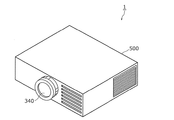
このように構成される照明装置1は、図2に示すように、第1ユニット100、第2ユニット200、第3ユニット300及び制御部400を、例えば図2に示すように筐体500に収納することで構成することができる。図2は、本発明の実施の形態1に係る照明装置1の外観斜視図である。
As shown in FIG. 2, the illuminating
[照明装置の動作]
次に、本発明の実施の形態1に係る照明装置1の動作について説明する。なお、本実施の形態では、半導体発光素子111が青色光を出射する場合について説明する。
[Operation of lighting device]
Next, operation | movement of the illuminating
第1ユニット100からは励起光として青色光が出射する。具体的には、半導体発光素子111から出射した青色光は、コリメートレンズ120によってコリメートされて直進光となって第1ユニット100から出射する。第1ユニット100から出射した青色光は第2ユニット200に入射する。
Blue light is emitted from the
第2ユニット200に入射した青色光は、ダイクロイックミラー220を透過して蛍光発光部材210に入射する。本実施の形態では、蛍光発光部材210が所定の回転数で回転しているので、第1ユニット100からの青色光は、蛍光発光部材210において、時間的に分割されて、照明用光発光領域212a、緑色蛍光発光領域212b1、赤色蛍光発光領域212b2及び透過領域212cに入射することになる。
The blue light incident on the
このとき、第1ユニット100の青色光が照明用光発光領域212aに入射した場合は、青色光が照明用光発光領域212aの黄色蛍光体によって黄色光となり、青色光と黄色光との混色である白色光(合成光)が照明用光発光領域212aから照明用の光として放射される。
At this time, when the blue light of the
また、第1ユニット100の青色光が緑色蛍光発光領域212b1に入射した場合は、青色光が緑色蛍光発光領域212b1の緑色蛍光体によって緑色光が生成され、当該緑色光(単色光)が緑色蛍光発光領域212b1から映像用の光として放射される。
When the blue light of the
また、第1ユニット100の青色光が赤色蛍光発光領域212b2に入射した場合は、青色光が赤色蛍光発光領域212b2の赤色蛍光体によって赤色光が生成され、当該赤色光(単色光)が赤色蛍光発光領域212b2から映像用の光として放射される。
When the blue light of the
また、第1ユニット100の青色光が透過領域212cに入射した場合は、当該青色光(単色光)が透過領域212cをそのまま透過して、当該青色光は透過領域212cから映像用の光として放射される。
Further, when the blue light of the
この結果、蛍光発光部材210からは照明用の光と映像用の光(赤色光、緑色光、青色光)とが時間的に分割されて出射する。本実施の形態では、照明用の光(白色光)、青色光、赤色光及び緑色光をこの順序で出射することを1サイクルとして、これを複数サイクル繰り返すことで照明用の光と映像用の光とが時間的に分割されて出射する。
As a result, illumination light and image light (red light, green light, and blue light) are temporally divided and emitted from the fluorescent
このとき、蛍光発光部材210から出射した照明用の光と映像用の光の一部(緑色光及び赤色光)は、ダイクロイックミラー220に向かって出射し、ダイクロイックミラー220で反射して第3ユニット300に導かれる。また、蛍光発光部材210から出射した映像用の他の一部(青色光)は、第1反射ミラー231、第2反射ミラー232及び第3反射ミラー233で順次反射して、ダイクロイックミラー220を透過して第3ユニット300に導かれる。
At this time, the illumination light and part of the image light (green light and red light) emitted from the fluorescent
このように、本実施の形態では、蛍光発光部材210(蛍光体ホイール)を回転させることによって映像用の光と照明用の光とが連続して生成されている。そして、蛍光発光部材210で生成された映像用の光と照明用の光とは、時間的に分割されて(つまり時分割で)第3ユニット300に入射する。
Thus, in the present embodiment, the image light and the illumination light are continuously generated by rotating the fluorescent light emitting member 210 (phosphor wheel). Then, the image light and the illumination light generated by the fluorescent
なお、本実施の形態では、映像用の光と照明用の光とが時分割で出射しているが、この場合、映像用の光(赤色光、緑色光、青色光)と照明用の光とは、人の目で認識できる速さよりも速いスピードで連続して出射している。例えば、マイクロ秒(μsec)の速さで連続的に出射している。マイクロ秒オーダーでは、光色は切り替わっているが、人の目で認識できる速さを超えているため、人の目には、それらの光が合成された色や映像として認識される。 In this embodiment, image light and illumination light are emitted in a time-sharing manner. In this case, image light (red light, green light, blue light) and illumination light are used. Is continuously emitted at a speed faster than the speed that can be recognized by human eyes. For example, the light is continuously emitted at a microsecond (μsec) speed. In the microsecond order, the light color is switched, but it exceeds the speed that can be recognized by the human eye, so that it is recognized by the human eye as a synthesized color or image.
第3ユニット300に入射した映像用の光及び照明用の光は、集光レンズ310、ロッドインテグレータ320及びレンズ群330を通って表示素子350に入射して、制御部400からの映像信号に基づいて所定の映像光(画像)及び照明光に形成されて表示素子350から出力される。
The image light and illumination light incident on the
そして、表示素子350から出力した映像光及び照明光は投射レンズ340を通って外部に出力されて、所定の照射領域に照射される。つまり、照明光と映像光とは、時間的に分割されて第3ユニット300から外部に出力して、照明装置1の外部の照射領域に照射される。この場合、例えば、照明光と映像光とを同時に出力することにより、照明領域の中に映像を表示することができる。また、照明光と映像光とを交互に出力することにより、照明と映像表示とを交互に切り替えて行うことができる。
Then, the image light and the illumination light output from the
[照明装置の効果]
上述のとおり、映像光と照明光とは、目的とするところが異なるので要求される光のスペクトルが異なる。
[Effect of lighting device]
As described above, the image light and the illumination light have different purposes, and therefore require different light spectra.
例えば、映像光は色再現範囲(画質)を高めることを目的としているので、例えばカラー画像の映像光では、図3に示すように、RGBの各色においてシャープなピーク波長を有するスペクトルであるとよい。図3は、RGBカラー画像における理想的な映像光のスペクトルの一例を示す図である。 For example, video light is intended to increase the color reproduction range (image quality), so for example, color image video light may have a spectrum having sharp peak wavelengths in each color of RGB as shown in FIG. . FIG. 3 is a diagram illustrating an example of an ideal video light spectrum in an RGB color image.
一方、照明光は照射対象物の見え(演色性)を高めることを目的としているので、例えば青色光の励起光とこの励起光で蛍光発光する黄色蛍光体とによって白色の照明光を得るには、図4に示すように、ブロードなスペクトルであるとよい。図4は、B−Yタイプの理想的な照明光のスペクトルの一例を示す図である。 On the other hand, the illumination light is intended to enhance the appearance (color rendering) of the object to be irradiated. For example, in order to obtain white illumination light using blue excitation light and a yellow phosphor that emits fluorescence with this excitation light. As shown in FIG. 4, a broad spectrum is preferable. FIG. 4 is a diagram illustrating an example of a BY-type ideal illumination light spectrum.
つまり、演色性の高い照明光のスペクトルと色再現範囲の高い映像光のスペクトルとを比べると、演色性の高い照明光のスペクトルには、映像光のスペクトルにおけるどのピーク波長の半値幅よりも大きい半値幅を持つピーク波長が含まれることになる。つまり、照明光のスペクトルには、映像光のスペクトルにおいて、映像用の光(赤色光、緑色光、青色光)のピーク波長の半値幅よりも大きい半値幅を持つピーク波長が含まれる。例えば、そのような照明光の幅広のピーク波長の半値幅は、映像用の光のどのピーク波長の半値幅に対しても2倍以上である。 In other words, comparing the spectrum of illumination light with high color rendering properties and the spectrum of image light with high color reproduction range, the spectrum of illumination light with high color rendering properties is larger than the half-width of any peak wavelength in the spectrum of image light. A peak wavelength having a half-value width is included. That is, the spectrum of illumination light includes a peak wavelength having a half-value width larger than the half-value width of the peak wavelength of image light (red light, green light, blue light) in the spectrum of image light. For example, the half-value width of the broad peak wavelength of such illumination light is twice or more than the half-value width of any peak wavelength of the image light.
本実施の形態では、第2ユニット200において第1ユニット100からの励起光を用いて蛍光発光させて照明用の光を生成し、第3ユニット300において第2ユニット200で生成した照明用の光を所定の照明光として外部に導いている。これにより、演色性の高い照明光を出力することができる。
In the present embodiment, the
また、第2ユニット200において映像用の光を生成し、第3ユニット300において第2ユニット200で生成した映像用の光を所定の映像光として外部に導いている。これにより、所望の映像光を出力することができる。
The
そして、本実施の形態では、照明用の光と映像用の光とが第2ユニット200において時分割で生成されているので、第3ユニット300では照明光と映像光とが時分割で生成されて外部に出力される。なお、本実施の形態では、照明光と映像光とを時分割で(すなわち、照明光と映像光とを人の目で認識できる速さよりも速いスピードで)出力している。これにより、ユーザには照明光と映像光とが同時に出力しているように認識させることができる。なお、照明光と映像光とが交互に切り替えて出力しているように認識させることもできる。
In the present embodiment, since the illumination light and the image light are generated in the
以上、本実施の形態における照明装置1によれば、演色性に優れた照明光と所望の映像光とを時間的に分割して出力することができる。つまり、演色性に優れた照明と所望の映像表示とを行うことができる。
As mentioned above, according to the illuminating
また、本実施の形態では、1つの蛍光発光部材210(蛍光体ホイール)に、その回転方向に分割された領域に、照明用光蛍光体が設けられた照明用光発光領域212a及び映像用光蛍光体が設けられた映像用光発光領域212bが割り当てられている。
Further, in the present embodiment, an illumination
これにより、演色性に優れた照明光と所望の映像光とが時分割で出力されるので、照明光と映像光とが合わされた照明画像を容易に出力させることができる。 Thereby, since the illumination light excellent in color rendering and the desired image light are output in a time division manner, an illumination image in which the illumination light and the image light are combined can be easily output.
(実施の形態1の変形例)
次に、本発明の実施の形態1の変形例について、図5を用いて説明する。図5は、本発明の実施の形態1の変形例に係る照明装置1Aの構成を示す図である。
(Modification of Embodiment 1)
Next, a modification of the first embodiment of the present invention will be described with reference to FIG. FIG. 5 is a diagram showing a configuration of an illuminating
本変形例における照明装置1Aが上記実施の形態1における照明装置1と異なる点は、第2ユニット200Aの構成である。
The difference between the
すなわち、上記実施の形態1では、蛍光発光部材210の蛍光発光部212が回転板211の回転方向に沿った領域のみに分割されており、その分割された領域に照明用光発光領域212a及び映像用光発光領域212bが割り当てられていた。
That is, in
これに対して、本変形例では、図5に示すように、蛍光発光部材210Aの蛍光発光部212Aが回転板211の径方向に同心状にも分割されており、その分割された領域に照明用光発光領域212a及び映像用光発光領域212bが割り当てられている。
On the other hand, in this modification, as shown in FIG. 5, the fluorescent
より具体的には、蛍光発光部材210Aの蛍光発光部212Aは、回転板211の径方向に同心円状に2つの領域に分割されている。そして、この2つの領域のうち内側の領域には、照明用光蛍光体が設けられた照明用光発光領域212aが割り当てられており、外側の領域には、映像用光蛍光体が設けられた映像用光発光領域212b及び透過領域212cが割り当てられている。なお、外側の領域は、回転板211の回転方向に沿って3つの領域に分割されており、映像用光発光領域212bである緑色蛍光発光領域212b1及び赤色蛍光発光領域212b2と透過領域212cとが回転方向に沿って割り当てられている。
More specifically, the fluorescent
さらに、本変形例における第2ユニット200Aには、さらに、第1ユニット100からの励起光を、照明用光蛍光体が設けられた照明用光発光領域212aと映像用光蛍光体が設けられた映像用光発光領域212bとを切り替えて照射するための光学部材240が設けられている。
Further, the
このような光学部材240としては、例えば、ガルバノミラーが用いられる。制御部400からの制御信号によって光学部材240を制御することによって、第1ユニット100の励起光は、内側の領域(照明用光発光領域212a)と外側の領域(映像用光発光領域212b、透過領域212c)とのいずれか一方に照射するように時間的に切り替えられる。具体的には、制御部400によってガルバノミラーの角度が制御される。
As such an
なお、本変形例でも、上記実施の形態1と同様に、蛍光発光部材210Aにおいて照明用の光と映像用の光とが生成されて、第2ユニット200Aから第3ユニット300に出射する。
In this modification as well, in the same manner as in the first embodiment, illumination light and image light are generated in the fluorescent
以上、本変形例における照明装置1Aによれば、実施の形態1と同様に、演色性に優れた照明光と所望の映像光とを時分割で外部に出力することができる。
As described above, according to
さらに、本変形例では、照明用光蛍光体と映像用光蛍光体とが回転板211の径方向に同心状に分割された領域に設けられている。また、第1ユニット100の励起光は、光学部材240によって切り替えられて照明用光蛍光体と映像用光蛍光体とに照射される。
Furthermore, in this modification, the illumination light phosphor and the image light phosphor are provided in a region that is concentrically divided in the radial direction of the
これにより、回転板211の回転方向には照明用の光と映像用の光とが合成されない。つまり、照明装置1Aから出力される映像光と照明光とを分離して形成することができる。これにより、実施の形態1と比べて、映像光(画像)の画質を向上させることができるとともに、照明光の明るさを大きくすることができる。
Thereby, the illumination light and the image light are not combined in the rotation direction of the
なお、本変形例では、回転板211の径方向に同心状に分割した2つの領域のうち、内側の領域には照明用光発光領域212aを割り当て、外側の領域には映像用光発光領域212bを割り当てたが、逆であってもよい。
In this modified example, among the two regions concentrically divided in the radial direction of the
(実施の形態2)
次に、本発明の実施の形態2に係る照明装置2について、図6を用いて説明する。図6は、本発明の実施の形態2に係る照明装置2の構成を示す図である。
(Embodiment 2)
Next, the illuminating
本実施の形態における照明装置2が上記実施の形態1における照明装置1と異なる点は、第2ユニット202の構成である。
The
本実施の形態における第2ユニット202は、実施の形態1と同様に、映像用の光及び照明用の光を生成して時間的に分割して出射する映像用光/照明用光生成ユニットであるが、本実施の形態では、ダイクロイックミラー220と、蛍光発光部材250と、色選択部材260とを備える。
Similarly to the first embodiment, the
本実施の形態における蛍光発光部材250は、回転するように構成された蛍光体ホイール(回転ホイール)であって、ドーナツ円板状(円環状)の回転板251と、回転板251に設けられた蛍光発光部252と、回転板251を回転させるためのモータ253とを有する。回転板251の回転に連動して蛍光発光部252が回転することで、蛍光発光部252から照明用の光が出射する。
The fluorescent
回転板251は、例えば透明基板であり、モータ253によって所定の回転数で回転する。モータ253は、制御部400からの駆動制御信号に基づいて駆動される。
The
蛍光発光部252は、回転板251の一方の面に設けられている。蛍光発光部252は、第1ユニット100からの励起光によって蛍光発光する蛍光体を有している。本実施の形態において、蛍光発光部252は、第1ユニット100からの励起光によって蛍光発光して照明用の光を生成する照明用光蛍光体を有する。
The fluorescent
照明用光蛍光体の材料は、実施の形態1と同様であり、例えば、第1ユニット100の励起光が青色光の場合、白色の照明光(白色光)を得るために、YAG系の黄色蛍光体を用いることができる。具体的には、透光性材料に照明用光蛍光体が含有された蛍光体含有部材が回転板251の一方の面の全面に形成されている。このように、青色光によって蛍光発光させた黄色光を用いて白色光を生成しているので、蛍光発光部材250からは、照明用の光に適したブロードなスペクトルの白色光が出射する。
The material of the illumination photophosphor is the same as that of the first embodiment. For example, when the excitation light of the
色選択部材260は、回転ホイールであって、ドーナツ円板状(円環状)の回転板261と、回転板261に設けられた色選択部262と、回転板261を回転させるためのモータ263とを有する。回転板261は、例えば透明基板であり、モータ263によって所定の回転数で回転する。モータ263は、制御部400からの駆動制御信号に基づいて駆動される。
The
色選択部262は、蛍光発光部252によって生成された照明光の色を選択して透過するカラーフィルタ部を有する。カラーフィルタ部は、蛍光発光部材250からダイクロイックミラー220に向かう方向の光については選択的に透過するように構成されている。本実施の形態において、カラーフィルタ部は、蛍光発光部材250(蛍光発光部252)で生成された照明用の光のうち赤色光を選択的に透過する赤色フィルタ262Rと、当該照明用の光のうち緑色光を選択的に透過する緑色フィルタ262Gと、当該照明用の光のうち青色光を選択的に透過する青色フィルタ262Bとを有する。
The
なお、本実施の形態において、赤色フィルタ262R、緑色フィルタ262B及び青色フィルタ262Bは、ダイクロイックフィルタであり、第1ユニット100からの蛍光発光部材250に向かう方向の励起光(青色光)については透過するように構成されている。
In the present embodiment, the
また、色選択部材260は、蛍光発光部252によって生成された照明用の光をそのまま透過する透過部262Tを有する。
In addition, the
カラーフィルタ部CF及び透過部262Tは、色選択部材260の回転方向に分割された回転板211の所定の領域に設けられている。具体的には、赤色フィルタ262R、緑色フィルタ262G、青色フィルタ262B及び透過部262Tは、色選択部材260の回転方向に4分割された回転板211の領域に設けられている。
The color filter portion CF and the
モータ263によって回転板261を回転させることによって、蛍光発光部材250からの照明用の光がカラーフィルタ部(赤色フィルタ262R、緑色フィルタ262G、青色フィルタ262B)及び透過部262Tを時分割で透過して、映像用の光(赤色光、緑色光、青色光)及び照明用の光として色選択部材260から出射する。
By rotating the
また、本実施の形態において、色選択部材260は、表示素子350と同期している。すなわち、制御部400からの制御信号によって、表示素子350(DMD)の微小ミラーの可動と色選択部材260(回転ホイール)の回転とが同期するように制御されている。さらに、色選択部材260の回転と蛍光発光部材250の回転とも同期させている。
In this embodiment, the
次に、本発明の実施の形態2に係る照明装置2の動作について説明する。なお、実施の形態1と異なる点を中心に説明する。
Next, operation | movement of the illuminating
第1ユニット100から出射した青色光は、第2ユニット200に入射し、ダイクロイックミラー220及び色選択部材260を透過して蛍光発光部材250に入射する。これにより、蛍光発光部材250からは白色光が出射する。また、蛍光発光部材250から出射した白色光は、色選択部材260に入射する。
The blue light emitted from the
このとき、色選択部材260は回転しているので、蛍光発光部材250からは白色光は時分割でカラーフィルタ部(赤色フィルタ262R、緑色フィルタ262G、青色フィルタ262B)及び透過部262Tに入射することになる。
At this time, since the
この場合、蛍光発光部材250の白色光が赤色フィルタ262Rに入射した場合は、白色光のうち赤色光だけが透過して映像用の光として放射される。
In this case, when the white light of the fluorescent
同様に、蛍光発光部材250の白色光が緑色フィルタ262Gに入射した場合は、白色光のうち緑色光だけが透過して映像用の光として放射される。
Similarly, when the white light of the fluorescent
同様に、蛍光発光部材250の白色光が青色フィルタ262Bに入射した場合は、白色光のうち青色光だけが透過して映像用の光として放射される。
Similarly, when the white light of the fluorescent
また、蛍光発光部材250の白色光が透過部262Tに入射した場合は、白色光はそのまま透過部262Tを透過して照明用の光として放射される。
Further, when the white light of the fluorescent
この結果、色選択部材260は回転にともなって、色選択部材260からは照明用の光と映像用の光(赤色光、緑色光、青色光)とが時分割で出射する。つまり、本実施の形態でも、第2ユニット200からは、照明用の光(白色光)、青色光、赤色光及び緑色光をこの順序で出射することを1サイクルとして、これを複数サイクル繰り返すことで照明用の光と映像用の光とが時分割で出射する。
As a result, as the
このように、本実施の形態では、色選択部材260を回転させることによって映像用の光と照明用の光とが連続して生成されて、時分割で第3ユニット300に入射する。
As described above, in the present embodiment, by rotating the
なお、第3ユニット300に入射した映像用の光及び照明用の光は、実施の形態1と同様に、所定の映像光及び照明光として時分割で外部に導かれる。
Note that the image light and illumination light incident on the
以上、本実施の形態における照明装置2によれば、実施の形態1と同様に、演色性に優れた照明光と所望の映像光とを時分割で外部に出力することができる。
As described above, according to the illuminating
(実施の形態3)
次に、本発明の実施の形態3に係る照明装置3について、図7を用いて説明する。図7は、本発明の実施の形態3に係る照明装置3の構成を示す図である。
(Embodiment 3)
Next, the illuminating
本実施の形態における照明装置3が上記実施の形態1における照明装置1と異なる点は、第2ユニット203の構成である。
The difference between the
本実施の形態における第2ユニット203は、映像用の光及び照明用の光を生成する映像用光/照明用光生成ユニットであり、照明用光生成部203Aと映像用光生成部203Bとを有する。つまり、本実施の形態では、映像用の光と照明用の光とは別のデバイスによって生成される。
The
照明用光生成部203Aは、蛍光発光部材270及びダイクロイックミラー220を備える。本実施の形態における蛍光発光部材270は、蛍光体ホイール(回転ホイール)であり、ドーナツ円板状(円環状)の回転板271と、回転板271に設けられた蛍光発光部272と、回転板271を回転させるためのモータ273とを有する。回転板271の回転に連動して蛍光発光部272が回転することで、蛍光発光部272から照明用の光が出射する。
The illumination
回転板271は、例えば透明基板であり、モータ273によって所定の回転数で回転する。モータ273は、制御部400からの駆動制御信号に基づいて駆動される。
The
蛍光発光部272は、回転板271の一方の面に設けられている。蛍光発光部272は、第1ユニット100からの励起光によって蛍光発光する蛍光体を有している。蛍光発光部272は、第1ユニット100からの励起光によって蛍光発光して照明用の光を生成する照明用光蛍光体を有する。
The fluorescent
本実施の形態において、蛍光発光部272は、蛍光体を蛍光発光させることによって第1の照明用の光(照明光A)を発する第1照明用光発光領域272Aと、蛍光体を蛍光発光させることによって第2の照明用の光(照明光B)を発する第2照明用光発光領域272Bとによって構成されている。第1の照明用の光と第2の照明用の光とは異なる色である。つまり、蛍光発光部材270は、複数色の照明用の光を生成する。例えば、このような照明用の光としては、昼白色、昼光色、電球色等の白色光、あるいは赤色等の有色光とすることができる。一例として、第1の照明用の光は昼光色であり、第2の照明用の光は電球色である。
In the present embodiment, the fluorescent
第1照明用光発光領域272Aには、第1ユニット100からの励起光によって蛍光発光する第1照明用光蛍光体が設けられている。また、第2照明用光発光領域272Bは、第1ユニット100からの励起光によって蛍光発光する第2照明用光蛍光体が設けられている。
In the first illumination
第1照明用光発光領域272A及び第2照明用光発光領域272Bは、回転方向に分割された回転板211の所定の領域に割り当てられている。なお、本実施の形態では、第1照明用光発光領域272Aの面積が第2照明用光発光領域272Bの面積よりも大きくなるように設定されている。
The first illumination
第1照明用光蛍光体及び第2照明用光蛍光体の材料の各々は、所望の色の照明光が得られるように、第1ユニット100の励起光に応じて選ぶことができる。本実施の形態では、第1の照明用の光と第2の照明用の光とが異なる色となるように各々の材料が選ばれている。
The materials of the first illumination light phosphor and the second illumination light phosphor can be selected according to the excitation light of the
例えば、第1及び第2照明用光蛍光体の材料は、例えば、第1ユニット100の励起光が青色光の場合、色温度の異なる白色の照明光(昼白色、昼光色、電球色等)を得るために、YAG系の黄色蛍光体と赤色蛍光体又は緑色蛍光体とを組み合わせている。具体的には、透光性材料にこれらの蛍光体が含有された蛍光体含有部材が第1照明用光発光領域272A及び第2照明用光発光領域272Bごとに回転板271の一方の面に形成されている。このように、本実施の形態でも、青色光によって蛍光発光させた黄色光を用いて白色光を生成しているので、蛍光発光部材270からは、照明用の光に適したブロードなスペクトルの白色光が出射する。
For example, when the excitation light of the
映像用光生成部203Bは、映像用の光を発する光源部280を有する。光源部280は、赤色光を発する赤色光源280Rと、緑色光を発する緑色光源280Gと、青色光を発する青色光源280Bとを有する。赤色光源280R、緑色光源280G及び青色光源280Bとしては、例えば、半導体レーザ又はLED等の半導体発光素子を用いることができる。本実施の形態では、半導体レーザを用いている。
The image
赤色光源280Rから出射した赤色光、緑色光源280Gから出射した緑色光及び青色光源280Bから出射した青色光の各々は、映像用の光として第3ユニット300に導かれる。なお、光源部280からの赤色光、緑色光及び青色光は、第2ユニット200において、蛍光発光部材270からの第1の照明用の光及び第2の照明用の光と同じ光路となって第3ユニット300に導かれる。
Each of the red light emitted from the
次に、本発明の実施の形態3に係る照明装置3の動作について説明する。なお、実施の形態1と異なる点を中心に説明する。
Next, operation | movement of the illuminating
第1ユニット100から出射した青色光は、第2ユニット200の照明用光生成部203Aに入射し、ダイクロイックミラー220を透過して蛍光発光部材270に入射する。
The blue light emitted from the
このとき、第1ユニット100の励起光が第1照明用光発光領域272Aに入射した場合は、第1照明用光発光領域272Aの第1照明用光蛍光体が励起光によって蛍光発光して第1の照明用の光として放射される。
At this time, if the excitation light of the
また、第1ユニット100の励起光が第2照明用光発光領域272Bに入射した場合は、第2照明用光発光領域272Bの第2照明用光蛍光体が励起光によって蛍光発光して第2の照明用の光として放射される。
In addition, when the excitation light of the
照明用光生成部203Aから出射する第1及び第2の照明用の光は、ダイクロイックミラー220で反射して第3ユニット300に導かれる。
The first and second illumination lights emitted from the illumination
一方、第2ユニット200の映像用光生成部203Bでは、光源部280において、赤色光、緑色光及び青色光が生成されて、映像用光生成部203Bから出射する。映像用光生成部203Bで生成された赤色光、緑色光及び青色光は、映像用の光として第3ユニット300に入射する。
On the other hand, in the video
このとき、照明用光生成部203Aと映像用光生成部203Bとは別のデバイスであるので、第1及び第2の照明用の光と映像用の光とは、別々のデバイスから別個独立して出射するが、照明用光生成部203A及び映像用光生成部203Bは、制御部400によって同期するように制御されている。
At this time, since the illumination
これにより、第1及び第2の照明用の光と映像用の光とは第2ユニット200で上乗せされて第3ユニット300に入射する。具体的には、照明用光生成部203A及び映像用光生成部203Bのいずれか一方が光を出力しているときはいずれか他方は光を出力しておらず、第1及び第2の照明用の光と映像用の光とは時分割で出力されて第3ユニット300に導かれる。
Accordingly, the first and second illumination light and the image light are added by the
なお、第3ユニット300に入射した第1及び第2の照明用の光と映像用の光とは、実施の形態1と同様に、所定の照明光及び映像光として時分割で外部に導かれる。
The first and second illumination light and video light incident on the
以上、本実施の形態における照明装置3によれば、実施の形態1と同様に、演色性に優れた照明光と所望の映像光とを時分割で外部に出力することができる。
As described above, according to the
さらに、本実施の形態では、照明用光生成部203Aと映像用光生成部203Bとが別のデバイスであるので、照明用の光と映像用の光とが合成されない。これにより、実施の形態1と比べて、映像光(画像)の画質を向上させることができるとともに、照明光の明るさを大きくすることができる。
Furthermore, in this embodiment, since the illumination
また、本実施の形態において、蛍光発光部材270は、複数色の照明用の光を生成している。これにより、目的に応じて照明光を切り替えて出力することができるので、様々なシーンの照明光を創出することができる。例えば、魚、肉又は野菜等の生鮮食品を主に照明する場合や人の肌を主に照明する場合とで出力する照明光の種類を切り替えることができる。 In the present embodiment, the fluorescent light emitting member 270 generates a plurality of colors of illumination light. Thereby, since illumination light can be switched and output according to the purpose, illumination light for various scenes can be created. For example, it is possible to switch the type of illumination light to be output depending on whether the fresh food such as fish, meat or vegetables is mainly illuminated or the human skin is mainly illuminated.
なお、本実施の形態では、第1及び第2の照明用の光(複数色の照明用の光)を生成したが、第1の照明用の光及び第2の照明用の光のいずれか一方、つまり、照明用の光は1種類であってもよい。 In the present embodiment, the first and second illumination lights (multiple-color illumination lights) are generated. However, either the first illumination light or the second illumination light is generated. On the other hand, that is, one type of illumination light may be used.
(その他変形例等)
以上、本発明に係る照明装置について、実施の形態1〜3及び変形例に基づいて説明したが、本発明は、上記の実施の形態及び変形例に限定されるものではない。
(Other variations)
As mentioned above, although the illuminating device concerning this invention was demonstrated based on Embodiment 1-3 and a modification, this invention is not limited to said embodiment and a modification.
例えば、上記実施の形態及び変形例において、蛍光発光部材210には励起光を透過する透過領域212cを設けたが、透過領域212cに代えて、励起光によって青色光を蛍光発光する青色蛍光体が設けられた青色蛍光発光領域としてもよい。
For example, in the above-described embodiment and modification, the fluorescent
また、上記実施の形態及び変形例において、第1ユニット100で生成する励起光は青色光としたが、これに限るものではない。例えば、第1ユニット100で生成する励起光を紫外線光(UV光)にしてもよい。この場合、蛍光発光部材210の透過領域212cに代えて、紫外線光で蛍光発光して青色光を生成する青色蛍光体が設けられた青色蛍光発光領域にすればよい。また、この場合、ダイクロイックミラー220としては、紫外線光は透過するが紫外線光よりも長い波長の光(可視光)は反射する特性となるように構成すればよい。
Moreover, in the said embodiment and modification, although the excitation light produced | generated with the
また、上記実施の形態及び変形例において、蛍光発光部材を回転させることによって照明用の光と映像用の光とを時分割で出射するように構成したが、蛍光発光部材を回転させることなくすることなく映像用の光及び照明用の光とを時分割で出射するように構成してもよい。 Moreover, in the said embodiment and modification, although it comprised so that the light for illumination and the light for an image | video may be radiate | emitted by time division by rotating a fluorescent light-emitting member, it does not rotate a fluorescent light-emitting member. Alternatively, the image light and the illumination light may be emitted in a time division manner.
また、上記実施の形態及び変形例において、照明用の光及び照明光は白色光(合成光)としたが、有色光又は単色光としても構わない。 Moreover, in the said embodiment and modification, although the light for illumination and illumination light were white light (synthetic light), you may be colored light or monochromatic light.
また、上記実施の形態及び変形例において、第1ユニット100、第2ユニット200及び第3ユニット300にレンズやミラー等の光学部材を適宜追加してもよい。
In the embodiment and the modification described above, an optical member such as a lens or a mirror may be appropriately added to the
また、上記実施の形態及び変形例において、光源として半導体レーザ又はLEDを用いたが、有機EL(Electro Luminescence)や無機EL等のEL素子等のその他の固体発光素子を用いてもよい。 Moreover, in the said embodiment and modification, although the semiconductor laser or LED was used as a light source, you may use other solid light emitting elements, such as EL elements, such as organic EL (Electro Luminescence) and inorganic EL.
その他、各実施の形態及び変形例に対して当業者が思いつく各種変形を施して得られる形態、又は、本発明の趣旨を逸脱しない範囲で各実施の形態及び変形例における構成要素及び機能を任意に組み合わせることで実現される形態も本発明に含まれる。 In addition, the form obtained by making various modifications conceived by those skilled in the art with respect to the respective embodiments and modifications, or the components and functions in the respective embodiments and modifications are arbitrarily selected without departing from the gist of the present invention. Embodiments realized by combining these are also included in the present invention.
1、1A、2、3 照明装置
100 第1ユニット
110 発光モジュール
111 半導体発光素子
120 コリメートレンズ
130 ヒートシンク
200、200A、202、203 第2ユニット
203A 照明用光生成部
203B 映像用光生成部
210、210A、250、270 蛍光発光部材
211、251、261、271 回転板
212、212A、252、272 蛍光発光部
212a 照明用光発光領域
212b 映像用光発光領域
212b1 緑色蛍光発光領域
212b2 赤色蛍光発光領域
212c 透過領域
213、253、263、273 モータ
220 ダイクロイックミラー
231 第1反射ミラー
232 第2反射ミラー
233 第3反射ミラー
240 光学部材
260 色選択部材
262 色選択部
262R 赤色フィルタ
262G 緑色フィルタ
262B 青色フィルタ
262T 透過部
272A 第1照明用光発光領域
272B 第2照明用光発光領域
280 光源部
280R 赤色光源
280G 緑色光源
280B 青色光源
300 第3ユニット
310 集光レンズ
320 ロッドインテグレータ
330 レンズ群
340 投射レンズ
350 表示素子
400 制御部
500 筐体
DESCRIPTION OF
340
Claims (16)
映像用の光及び照明用の光を生成して時間的に分割して出射する第2ユニットと、
前記第2ユニットで生成された前記映像用の光及び前記照明用の光を所定の映像光及び照明光として外部に導くための第3ユニットとを備え、
前記照明用の光は、前記励起光によって蛍光体を蛍光発光させることにより生成され、
前記照明光と前記映像光とは、時間的に分割されて前記第3ユニットから外部に出力され、
前記照明光のスペクトルには、前記映像光のスペクトルにおける前記映像用の光のピーク波長の半値幅よりも大きい半値幅を持つピーク波長が含まれる
照明装置。 A first unit for generating excitation light;
A second unit that generates image light and illumination light and divides it in time and emits it;
A third unit for guiding the image light and the illumination light generated by the second unit to the outside as predetermined image light and illumination light, and
The illumination light is generated by causing a fluorescent material to emit fluorescence with the excitation light,
The illumination light and the image light are temporally divided and output from the third unit to the outside.
The illumination device includes a peak wavelength having a half-value width larger than a half-value width of a peak wavelength of the image light in the spectrum of the image light .
請求項1に記載の照明装置。 The illuminating device according to claim 1, wherein the second unit includes a fluorescent light emitting member having an illumination light phosphor that emits fluorescence by the excitation light and generates a part of the illumination light.
請求項2に記載の照明装置。 The lighting apparatus according to claim 2, wherein the fluorescent light emitting member further includes a video light fluorescent material that generates fluorescent light by the excitation light to generate the video light.
前記照明用光蛍光体及び前記映像用光蛍光体は、所定の領域に分割されて前記回転板に設けられており、
前記励起光は、時間的に分割されて前記照明用光蛍光体と前記映像用光蛍光体とに照射される
請求項3に記載の照明装置。 The fluorescent light emitting member is a phosphor wheel having a rotating plate,
The illumination light phosphor and the video light phosphor are divided into predetermined regions and provided on the rotating plate,
The illuminating device according to claim 3, wherein the excitation light is temporally divided and applied to the illumination light phosphor and the video light phosphor.
請求項4に記載の照明装置。 The illuminating device according to claim 4, wherein the illumination light phosphor and the video light phosphor are provided in a region divided in a rotation direction of the rotating plate.
請求項4に記載の照明装置。 The illuminating device according to claim 4, wherein the illumination photophosphor and the video photophosphor are provided in a region concentrically divided in a radial direction of the rotating plate.
請求項6に記載の照明装置。 The illuminating device according to claim 6, wherein the second unit further includes an optical member for switching and irradiating the excitation light between the illumination light phosphor and the video light phosphor.
請求項5〜7のいずれか1項に記載の照明装置。 The rotating plate includes an illumination light emitting region provided with the illumination light phosphor, an image light emitting region provided with the image light phosphor, and a transmission region transmitting the excitation light. Item 8. The lighting device according to any one of Items 5 to 7.
前記映像用光蛍光体は、前記青色光によって赤色光を蛍光発光する赤色蛍光体と、前記青色光によって緑色光を蛍光発光する緑色蛍光体とを含み、
前記映像光発光領域は、前記赤色蛍光体が設けられた赤色蛍光発光領域と、前記緑色蛍光体が設けられた緑色蛍光発光領域とを有し、
前記透過領域は、前記青色光が透過する
請求項8に記載の照明装置。 The excitation light is blue light,
The video light phosphor includes a red phosphor that emits red light by the blue light, and a green phosphor that emits green light by the blue light,
The video light emitting region has a red fluorescent light emitting region provided with the red phosphor, and a green fluorescent light emitting region provided with the green phosphor,
The lighting device according to claim 8, wherein the blue light is transmitted through the transmission region.
前記色選択部材は、前記蛍光発光部材によって生成された前記照明用の光の色を選択して透過するカラーフィルタ部と、前記照明用の光を透過する透過部とを有する
請求項2に記載の照明装置。 The second unit further includes a color selection member,
The color selection member includes a color filter unit that selects and transmits the color of the illumination light generated by the fluorescent light emitting member, and a transmission unit that transmits the illumination light. Lighting equipment.
前記色選択部材は、前記蛍光体ホイールと同期して回転する
請求項10に記載の照明装置。 The fluorescent light emitting member is a phosphor wheel having a rotating plate,
The lighting device according to claim 10, wherein the color selection member rotates in synchronization with the phosphor wheel.
請求項11に記載の照明装置。 The lighting device according to claim 11, wherein the color filter unit and the transmission unit are provided in a region divided in a rotation direction of the color selection member.
前記赤色フィルタ、前記緑色フィルタ及び前記青色フィルタは、前記色選択部材の回転方向に分割された領域に設けられている
請求項12に記載の照明装置。 The color filter unit includes a red filter that selectively transmits red light in the illumination light, a green filter that selectively transmits green light in the illumination light, and blue light in the illumination light. And a blue filter that selectively transmits
The lighting device according to claim 12, wherein the red filter, the green filter, and the blue filter are provided in a region divided in a rotation direction of the color selection member.
請求項2に記載の照明装置。 The lighting device according to claim 2, wherein the second unit further includes a light source unit that emits the video light.
前記赤色光、前記緑色光及び前記青色光は、前記映像用の光として前記第3ユニットに導かれる
請求項14に記載の照明装置。 The light source unit includes a red light source that emits red light, a green light source that emits green light, and a blue light source that emits blue light,
The lighting device according to claim 14, wherein the red light, the green light, and the blue light are guided to the third unit as light for the video.
請求項14又は15に記載の照明装置。 The lighting device according to claim 14 or 15, wherein the fluorescent light-emitting member generates light for illumination of a plurality of colors.
Priority Applications (4)
| Application Number | Priority Date | Filing Date | Title |
|---|---|---|---|
| JP2013229769A JP6233572B2 (en) | 2013-11-05 | 2013-11-05 | Lighting device |
| DE201410115964 DE102014115964A1 (en) | 2013-11-05 | 2014-11-03 | lighting device |
| US14/532,390 US9753275B2 (en) | 2013-11-05 | 2014-11-04 | Illumination apparatus |
| CN201420652482.4U CN204403814U (en) | 2013-11-05 | 2014-11-04 | Lighting device |
Applications Claiming Priority (1)
| Application Number | Priority Date | Filing Date | Title |
|---|---|---|---|
| JP2013229769A JP6233572B2 (en) | 2013-11-05 | 2013-11-05 | Lighting device |
Publications (2)
| Publication Number | Publication Date |
|---|---|
| JP2015090403A JP2015090403A (en) | 2015-05-11 |
| JP6233572B2 true JP6233572B2 (en) | 2017-11-22 |
Family
ID=52829888
Family Applications (1)
| Application Number | Title | Priority Date | Filing Date |
|---|---|---|---|
| JP2013229769A Active JP6233572B2 (en) | 2013-11-05 | 2013-11-05 | Lighting device |
Country Status (4)
| Country | Link |
|---|---|
| US (1) | US9753275B2 (en) |
| JP (1) | JP6233572B2 (en) |
| CN (1) | CN204403814U (en) |
| DE (1) | DE102014115964A1 (en) |
Families Citing this family (19)
| Publication number | Priority date | Publication date | Assignee | Title |
|---|---|---|---|---|
| JP5637274B2 (en) * | 2012-12-26 | 2014-12-10 | 株式会社リコー | Light source device and projector using the same |
| JP6410079B2 (en) | 2014-06-26 | 2018-10-24 | パナソニックIpマネジメント株式会社 | Optical projection device and illumination device using the same |
| JP6167316B2 (en) * | 2014-06-30 | 2017-07-26 | パナソニックIpマネジメント株式会社 | Autonomous traveling vacuum cleaner |
| CN107077050B (en) * | 2014-09-30 | 2019-08-13 | Nec显示器解决方案株式会社 | Lighting device, wheel degradation detection and projector |
| JP6544676B2 (en) | 2015-03-11 | 2019-07-17 | パナソニックIpマネジメント株式会社 | Lighting device |
| US9851552B2 (en) * | 2015-06-01 | 2017-12-26 | Canon Kabushiki Kaisha | Image display apparatus |
| JP2018169413A (en) * | 2015-08-28 | 2018-11-01 | パナソニックIpマネジメント株式会社 | Lighting device and lighting system |
| JP2017123317A (en) * | 2016-01-08 | 2017-07-13 | パナソニックIpマネジメント株式会社 | Luminaire |
| JP6967689B2 (en) * | 2016-03-15 | 2021-11-17 | パナソニックIpマネジメント株式会社 | Light source device and projection type image display device |
| US10162252B2 (en) * | 2016-07-28 | 2018-12-25 | Panasonic Intellectual Property Management Co., Ltd. | Phosphor disc, phosphor wheel, light source device, projection display apparatus, and manufacturing method of phosphor disc |
| JP2018022781A (en) | 2016-08-03 | 2018-02-08 | パナソニックIpマネジメント株式会社 | Optical device |
| JP6796751B2 (en) * | 2016-09-26 | 2020-12-09 | パナソニックIpマネジメント株式会社 | Light source device and projection type image display device |
| JP2018136506A (en) * | 2017-02-23 | 2018-08-30 | 株式会社リコー | Lighting device and image projector device |
| CN109143744B (en) * | 2017-06-15 | 2021-06-29 | 深圳光峰科技股份有限公司 | Light source system and projection system using same |
| CN110133950A (en) * | 2018-02-09 | 2019-08-16 | 中强光电股份有限公司 | Lighting system and projection arrangement |
| CN110794643B (en) * | 2018-08-03 | 2021-07-23 | 台达电子工业股份有限公司 | Phase correction method and laser projector |
| WO2020153573A1 (en) * | 2019-01-22 | 2020-07-30 | 엘지전자 주식회사 | Projector |
| TWI732287B (en) * | 2019-09-03 | 2021-07-01 | 美商晶典有限公司 | Laser projection optical light source architecture |
| JP2021189390A (en) * | 2020-06-04 | 2021-12-13 | セイコーエプソン株式会社 | Illumination device and projector |
Family Cites Families (13)
| Publication number | Priority date | Publication date | Assignee | Title |
|---|---|---|---|---|
| US6259103B1 (en) * | 1998-11-12 | 2001-07-10 | The United States Of America As Represented By The Secretary Of The Air Force | Light beam detector |
| US7050120B2 (en) * | 2002-01-31 | 2006-05-23 | Hewlett-Packard Development Company, L.P. | Display device with cooperative color filters |
| TWI247186B (en) * | 2004-06-18 | 2006-01-11 | Delta Electronics Inc | Multi-function color wheel |
| US7404652B2 (en) * | 2004-12-15 | 2008-07-29 | Avago Technologies Ecbu Ip Pte Ltd | Light-emitting diode flash module with enhanced spectral emission |
| JP2009199854A (en) | 2008-02-21 | 2009-09-03 | Seiko Epson Corp | Projector |
| JP2011108502A (en) * | 2009-11-18 | 2011-06-02 | Stanley Electric Co Ltd | Light source device and illuminating device |
| US8684560B2 (en) | 2009-11-18 | 2014-04-01 | Stanley Electric Co., Ltd. | Semiconductor light source apparatus and lighting unit |
| JP5491888B2 (en) | 2010-02-05 | 2014-05-14 | 日立コンシューマエレクトロニクス株式会社 | Projection display |
| JP5542632B2 (en) * | 2010-11-18 | 2014-07-09 | 三菱電機株式会社 | Projection-type image display device |
| US9989837B2 (en) | 2011-08-04 | 2018-06-05 | Appotronics Corporation Limited | Lighting device and projection device |
| CN102707551B (en) * | 2011-08-04 | 2015-04-29 | 深圳市光峰光电技术有限公司 | Lighting device and projection device |
| CN102645822B (en) * | 2011-11-28 | 2014-12-10 | 深圳市光峰光电技术有限公司 | Projecting apparatus and control method thereof |
| CN102854728B (en) | 2011-12-18 | 2016-03-16 | 深圳市光峰光电技术有限公司 | Light-source system and projection arrangement |
-
2013
- 2013-11-05 JP JP2013229769A patent/JP6233572B2/en active Active
-
2014
- 2014-11-03 DE DE201410115964 patent/DE102014115964A1/en not_active Withdrawn
- 2014-11-04 US US14/532,390 patent/US9753275B2/en not_active Expired - Fee Related
- 2014-11-04 CN CN201420652482.4U patent/CN204403814U/en not_active Expired - Fee Related
Also Published As
| Publication number | Publication date |
|---|---|
| US20150124431A1 (en) | 2015-05-07 |
| CN204403814U (en) | 2015-06-17 |
| DE102014115964A1 (en) | 2015-05-07 |
| JP2015090403A (en) | 2015-05-11 |
| US9753275B2 (en) | 2017-09-05 |
Similar Documents
| Publication | Publication Date | Title |
|---|---|---|
| JP6233572B2 (en) | Lighting device | |
| JP6205835B2 (en) | LIGHTING DEVICE, PROJECTION DEVICE PROVIDED WITH THIS LIGHTING DEVICE, AND LIGHTING METHOD | |
| JP5714089B2 (en) | Lighting device and method of operating lighting device | |
| JP6296312B2 (en) | Light source system and associated projection system | |
| US9250506B2 (en) | Illumination light source device and projector provided with the same, and control method of the projector | |
| JP5987368B2 (en) | Illumination device and projection device | |
| JP5370764B2 (en) | Light source device and projector | |
| US7607784B2 (en) | Light emission method, light emitting apparatus and projection display apparatus | |
| JP6056293B2 (en) | Illumination light source device, projection device equipped with this illumination light source device, and control method of projection device | |
| US9069162B2 (en) | Lighting device, method and light wavelength conversion wheel assembly for color tuning thereof | |
| US8523924B2 (en) | Colored and white light generating lighting device | |
| JP4046585B2 (en) | LIGHTING DEVICE AND PROJECTION DISPLAY DEVICE USING THE LIGHTING DEVICE | |
| JP5494053B2 (en) | projector | |
| US9606428B2 (en) | Illuminating optical device, projector and method of controlling an illuminating optical device | |
| CN107430319B (en) | Projector and image light projection method | |
| CN103792635A (en) | Wavelength conversion wheel module and lighting system | |
| EP3698541B1 (en) | Enhanced white light for projection lighting | |
| JP6814392B2 (en) | Light source device and projection device | |
| JP5762198B2 (en) | Optical device and projector device | |
| JP5672353B2 (en) | Control method of light source device | |
| JP2016177060A (en) | Color filter device and image projection device | |
| JP2015090432A (en) | Illumination device, projection display device and illumination method | |
| JP2004302357A (en) | Light source device of projection display device | |
| JP2013045676A (en) | Light source device and lighting system |
Legal Events
| Date | Code | Title | Description |
|---|---|---|---|
| A621 | Written request for application examination |
Free format text: JAPANESE INTERMEDIATE CODE: A621 Effective date: 20160805 |
|
| A977 | Report on retrieval |
Free format text: JAPANESE INTERMEDIATE CODE: A971007 Effective date: 20170531 |
|
| A131 | Notification of reasons for refusal |
Free format text: JAPANESE INTERMEDIATE CODE: A131 Effective date: 20170606 |
|
| A521 | Written amendment |
Free format text: JAPANESE INTERMEDIATE CODE: A523 Effective date: 20170728 |
|
| TRDD | Decision of grant or rejection written | ||
| A01 | Written decision to grant a patent or to grant a registration (utility model) |
Free format text: JAPANESE INTERMEDIATE CODE: A01 Effective date: 20171003 |
|
| A61 | First payment of annual fees (during grant procedure) |
Free format text: JAPANESE INTERMEDIATE CODE: A61 Effective date: 20171010 |
|
| R151 | Written notification of patent or utility model registration |
Ref document number: 6233572 Country of ref document: JP Free format text: JAPANESE INTERMEDIATE CODE: R151 |