JP6233253B2 - Lubrication control device - Google Patents
Lubrication control device Download PDFInfo
- Publication number
- JP6233253B2 JP6233253B2 JP2014188151A JP2014188151A JP6233253B2 JP 6233253 B2 JP6233253 B2 JP 6233253B2 JP 2014188151 A JP2014188151 A JP 2014188151A JP 2014188151 A JP2014188151 A JP 2014188151A JP 6233253 B2 JP6233253 B2 JP 6233253B2
- Authority
- JP
- Japan
- Prior art keywords
- oil
- transmission
- temperature
- valve
- engine
- Prior art date
- Legal status (The legal status is an assumption and is not a legal conclusion. Google has not performed a legal analysis and makes no representation as to the accuracy of the status listed.)
- Active
Links
Images


Landscapes
- General Details Of Gearings (AREA)
Description
本発明は、潤滑制御装置に関する。 The present invention relates to a lubrication control device.
従来、変速機のオイルの温度を調節する装置がある。例えば、特許文献1には、互いに直列に接続された水冷オイルクーラおよび空冷オイルクーラを具え、車両用自動変速機のオイルポンプ、油圧制御回路および変速機構の潤滑回路を流通して循環する作動油の冷却を行う作動油冷却装置において、作動油温が所定値以下、かつオイルポンプにて生成される作動油ライン圧が所定値以上の場合にのみ、作動油を水冷オイルクーラおよび空冷オイルクーラをバイパスさせてオイルポンプ、油圧制御回路および潤滑回路を循環させるクーラバイパス弁と、作動油温を検知して、当該温度が所要の値に達していない場合に、作動油を空冷オイルクーラのみをバイパスさせてオイルポンプ、油圧制御回路および潤滑回路を循環させるバイパス弁とを設けた車両用自動変速機の作動油冷却装置の技術が開示されている。 Conventionally, there is a device for adjusting the temperature of oil in a transmission. For example, Patent Document 1 discloses a hydraulic oil that includes a water-cooled oil cooler and an air-cooled oil cooler connected in series with each other, and circulates through an oil pump of a vehicle automatic transmission, a hydraulic control circuit, and a lubricating circuit of a transmission mechanism. In the hydraulic oil cooler that cools the hydraulic oil, the hydraulic oil is cooled by the water-cooled oil cooler and the air-cooled oil cooler only when the hydraulic oil temperature is lower than the predetermined value and the hydraulic oil line pressure generated by the oil pump is higher than the predetermined value. Cooler bypass valve that bypasses and circulates oil pump, hydraulic control circuit and lubrication circuit and hydraulic oil temperature is detected, and when the temperature does not reach the required value, hydraulic oil is bypassed only to air-cooled oil cooler Disclosed is a technology of a hydraulic oil cooling device for an automatic transmission for a vehicle provided with an oil pump, a hydraulic control circuit, and a bypass valve for circulating a lubrication circuit. It has been.
特許文献1には、作動油温が低い場合、水冷オイルクーラにおいてエンジン冷却水によって作動油が暖められることとなり、作動油の温度上昇が促進されると記載されている。特許文献1の車両用自動変速機の作動油冷却装置では、オイルクーラを経由する油路と、オイルクーラをバイパスする油路とが潤滑回路よりも上流側で合流する構成となっている。 Patent Document 1 describes that when the hydraulic oil temperature is low, the hydraulic oil is warmed by the engine cooling water in the water-cooled oil cooler, and the temperature rise of the hydraulic oil is promoted. In the hydraulic oil cooling device for an automatic transmission for a vehicle disclosed in Patent Document 1, an oil passage that passes through an oil cooler and an oil passage that bypasses the oil cooler are joined on the upstream side of the lubrication circuit.
オイルクーラを経由する油路と、オイルクーラをバイパスする油路とが潤滑回路よりも上流側で合流する構成である場合、オイルクーラにおいて温められたオイルにバイパス路を経由したオイルが混ざってしまう。このため、冷間時に被潤滑部に供給されるオイルの温度があまり高くならず、変速機の損失が低下しにくいという問題がある。 If the oil path that passes through the oil cooler and the oil path that bypasses the oil cooler merge on the upstream side of the lubrication circuit, the oil that has been warmed in the oil cooler will mix with the oil that passed through the bypass path . For this reason, there is a problem that the temperature of the oil supplied to the lubricated part is not so high when it is cold, and the loss of the transmission is hardly reduced.
本発明の目的は、変速機の損失を適切に低減させることができる潤滑制御装置を提供することである。 The objective of this invention is providing the lubrication control apparatus which can reduce the loss of a transmission appropriately.
本発明の潤滑制御装置は、変速機のオイルを送り出すオイルポンプと、前記オイルポンプと前記変速機の被潤滑部との間に接続され、エンジン内を循環する液状媒体と前記オイルとの熱交換を行う熱交換器と、前記熱交換器よりも前記オイルポンプ側と前記熱交換器よりも前記被潤滑部側とを接続するバイパス路と、前記オイルの油圧に応じて前記バイパス路を開閉するバイパスバルブと、前記バイパス路における前記バイパスバルブよりも前記被潤滑部側に接続された制御バルブとを備え、前記制御バルブは、前記バイパスバルブを経由した前記オイルが流入する流入ポートと、前記流入ポートから流入した前記オイルを前記被潤滑部側に供給する供給ポートと、前記流入ポートから流入した前記オイルをオイルパンに排出する排出ポートと、を有し、前記制御バルブは、前記オイルの油温に応じて前記流入ポートから前記排出ポートへ流れる前記オイルの排出量を変化させ、かつ、前記油温が低い場合の前記排出量を前記油温が高い場合の前記排出量以上とすることを特徴とする。 The lubrication control device according to the present invention includes an oil pump that sends out oil of a transmission, and a heat exchange between the oil and a liquid medium that is connected between the oil pump and the lubricated portion of the transmission and circulates in the engine. A heat exchanger that performs the operation, a bypass path that connects the oil pump side with respect to the heat exchanger and the lubricated part side with respect to the heat exchanger, and opens and closes the bypass path according to the oil pressure of the oil A bypass valve, and a control valve connected to the lubricated portion side of the bypass passage in the bypass path, the control valve including an inflow port through which the oil flows through the bypass valve, and the inflow A supply port for supplying the oil flowing in from the port to the lubricated part side, and a discharge port for discharging the oil flowing in from the inflow port to the oil pan The control valve changes a discharge amount of the oil flowing from the inflow port to the discharge port according to an oil temperature of the oil, and changes the discharge amount when the oil temperature is low. It is more than the said discharge | emission amount in case oil temperature is high, It is characterized by the above-mentioned.
本発明に係る潤滑制御装置の制御バルブは、オイルの油温に応じて流入ポートから排出ポートへ流れるオイルの排出量を変化させ、かつ、油温が低い場合の排出量を油温が高い場合の排出量以上とする。本発明に係る潤滑制御装置によれば、変速機の損失を適切に低減させることができるという効果を奏する。 The control valve of the lubrication control device according to the present invention changes the amount of oil flowing from the inlet port to the outlet port according to the oil temperature, and the amount of oil discharged when the oil temperature is low is high. Or more. According to the lubrication control device of the present invention, there is an effect that the loss of the transmission can be appropriately reduced.
以下に、本発明の実施形態に係る潤滑制御装置につき図面を参照しつつ詳細に説明する。なお、この実施形態によりこの発明が限定されるものではない。また、下記の実施形態における構成要素には、当業者が容易に想定できるものあるいは実質的に同一のものが含まれる。 Hereinafter, a lubrication control device according to an embodiment of the present invention will be described in detail with reference to the drawings. In addition, this invention is not limited by this embodiment. In addition, constituent elements in the following embodiments include those that can be easily assumed by those skilled in the art or those that are substantially the same.
[実施形態]
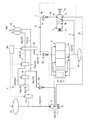
図1から図3を参照して、実施形態について説明する。本実施形態は、潤滑制御装置に関する。図1は、本発明の実施形態に係る変速機の概略構成図、図2は、実施形態に係る潤滑制御装置の供給状態を示す図、図3は、比較例の油路構成を示す図、図4は、オイルの動粘度と損失トルクとの関係の一例を示す図である。
[Embodiment]
The embodiment will be described with reference to FIGS. 1 to 3. The present embodiment relates to a lubrication control device. 1 is a schematic configuration diagram of a transmission according to an embodiment of the present invention, FIG. 2 is a diagram illustrating a supply state of a lubrication control device according to the embodiment, and FIG. 3 is a diagram illustrating an oil path configuration of a comparative example, FIG. 4 is a diagram illustrating an example of the relationship between the kinematic viscosity of oil and the loss torque.
図1に示す本実施形態の変速機3は、有段式の自動変速機である。本実施形態の変速機3は、動力源としてエンジン12を有する車両に搭載されている。変速機3は、係合装置としてクラッチやブレーキを有している。変速機3は、係合状態とされる係合装置の組み合わせに応じた変速比でエンジン12の回転を伝達する。図1に示すように、変速機3は、潤滑制御装置1と、変速機油路13と、AT変速制御部14と、トルクコンバータ19を含んで構成されている。潤滑制御装置1は、オイルポンプ2と、熱交換器4と、バイパス路5と、バイパスバルブ6と、制御バルブ7と、を含んで構成されている。
A
変速機3のオイルパン11には、トランスミッションオイル8が貯留されている。トランスミッションオイル8は、変速機3のオイルであり、変速機3の各部を循環する。オイルポンプ2は、オイルパン11に貯留されているトランスミッションオイル8を吸引し、加圧して送り出す。オイルポンプ2によって送り出されたトランスミッションオイル8は、変速機3内を循環した後にオイルパン11に戻される。
変速機油路13は、吸入油路13a、吐出油路13b、第一油路13c、第二油路13d、第三油路13e、第四油路13f、第五油路13g、係合側供給油路13h、解放側供給油路13i、潤滑系油路13jおよび戻し油路13kを有する。
The
吸入油路13aは、オイルパン11とオイルポンプ2の吸入ポートとを接続する。吐出油路13bは、オイルポンプ2の吐出ポートに接続されている。吐出油路13bは、AT変速制御部14に接続されている。AT変速制御部14は、変速機3の各係合装置に対して供給する油圧を制御する。プライマリレギュレータバルブ15は、吐出油路13bおよび第一油路13cにそれぞれ接続されている。プライマリレギュレータバルブ15は、吐出油路13bの油圧を所定のライン圧に調圧する。調圧の結果として余剰となったトランスミッションオイル8は、プライマリレギュレータバルブ15から第一油路13cに排出される。
The
第一油路13cにおけるプライマリレギュレータバルブ15側と反対側の端部には、第二油路13dおよび第三油路13eが接続されている。第三油路13eには、セカンダリレギュレータバルブ16が配置されている。セカンダリレギュレータバルブ16は、第一油路13c、第二油路13dおよび第三油路13eの油圧をライン圧以下の所定の目標圧に調圧する。調圧の結果として余剰となったトランスミッションオイル8は、セカンダリレギュレータバルブ16から第五油路13gに排出される。第二油路13dにおける下流側には、ロックアップコントロールバルブ17が配置されている。ロックアップコントロールバルブ17は、第二油路13dおよび第四油路13fと接続されており、第四油路13fに供給する油圧を制御する。ロックアップコントロールバルブ17は、第二油路13dの圧力をロックアップクラッチ19aにおいて必要とされる油圧に調圧して第四油路13fに供給する。
A
ロックアップリレーバルブ18は、トルクコンバータ19が有するロックアップクラッチ19aの解放、係合の切り替えを制御する。ロックアップリレーバルブ18は、第四油路13f、第五油路13g、係合側供給油路13h、解放側供給油路13iおよび潤滑系油路13jとそれぞれ接続されている。係合側供給油路13hおよび解放側供給油路13iは、トルクコンバータ19への供給油路である。係合側供給油路13hは、ロックアップクラッチ19aを係合させる向きの油圧を発生させる係合油圧室に接続されている。係合側供給油路13hを介してトルクコンバータ19の係合油圧室に供給される油圧は、ロックアップクラッチ19aの入力側の摩擦係合要素と出力側の摩擦係合要素を係合させる押圧力を発生させる。係合側供給油路13hを介してトルクコンバータ19に供給される油圧は、例えば、ロックアップピストンを係合方向に押圧してロックアップクラッチ19aを係合させる。
The
解放側供給油路13iは、ロックアップクラッチ19aを解放させる向きの油圧を発生させる解放油圧室に接続されている。解放側供給油路13iを介してトルクコンバータ19の解放油圧室に供給される油圧は、ロックアップクラッチ19aの入力側の摩擦係合要素と出力側の摩擦係合要素とを離間させる押圧力を発生させる。解放側供給油路13iを介してトルクコンバータ19に供給される油圧は、例えば、ロックアップピストンを解放方向に押圧してロックアップクラッチ19aを解放させる。
The release-side
第五油路13gには、戻し油路13kが接続されている。戻し油路13kは、第五油路13gと吸入油路13aとを接続している。戻し油路13kは、オイルポンプ2によって変速機油路13を介して圧送されるトランスミッションオイル8のうち、余剰分を吸入油路13aに供給する油路である。戻し油路13kには、チェックバルブ22が配置されている。チェックバルブ22は、熱交換器4へ向けてトランスミッションオイル8が流れるように、第五油路13gの油圧を調圧する。例えば、チェックバルブ22の開弁圧は、後述するトルクコンバータチェックバルブ20の開弁圧よりも高くされる。
A
潤滑系油路13jにおいて、ロックアップリレーバルブ18と熱交換器4との間には、トルクコンバータチェックバルブ20が接続されている。トルクコンバータチェックバルブ20は、トルクコンバータ19側から熱交換器4側へのトランスミッションオイル8の流れを許容し、熱交換器4側からトルクコンバータ19側へのトランスミッションオイル8の流れを規制する。トルクコンバータチェックバルブ20は、熱交換器4側の油圧と比べてトルクコンバータ19側の油圧が所定圧以上高い場合に開弁する。
A torque
制御部50は、電子制御ユニット等の制御装置であり、変速機3を制御する。制御部50は、プライマリレギュレータバルブ15、セカンダリレギュレータバルブ16、ロックアップコントロールバルブ17およびロックアップリレーバルブ18を制御する。また、制御部50は、AT変速制御部14によって変速機3の変速を制御する。
The
制御部50によるロックアップリレーバルブ18の制御について説明する。制御部50は、ロックアップクラッチ19aを解放する場合、ロックアップリレーバルブ18によって第四油路13fと解放側供給油路13iとを連通し、かつ係合側供給油路13hと潤滑系油路13jとを連通する。これにより、オイルポンプ2からロックアップコントロールバルブ17を介して供給されるトランスミッションオイル8は、第四油路13fから解放側供給油路13iを経由してトルクコンバータ19に流入し、ロックアップクラッチ19aを解放させる。トルクコンバータ19から流出するトランスミッションオイル8は、係合側供給油路13hから潤滑系油路13jへ流れる。
The control of the
制御部50は、ロックアップクラッチ19aを係合する場合、ロックアップリレーバルブ18によって第四油路13fと係合側供給油路13hとを連通し、かつ第五油路13gと潤滑系油路13jとを連通する。ロックアップコントロールバルブ17から第四油路13fおよび係合側供給油路13hを介してトルクコンバータ19に流入するトランスミッションオイル8は、ロックアップクラッチ19aを係合させる。セカンダリレギュレータバルブ16から第五油路13gに排出されたトランスミッションオイル8は、ロックアップリレーバルブ18を介して潤滑系油路13jに流入する。
When engaging the lockup clutch 19a, the
潤滑系油路13jは、ロックアップリレーバルブ18と被潤滑部30とを接続する油路である。潤滑系油路13jには、上流側から順に、トルクコンバータチェックバルブ20、および熱交換器4が接続されている。被潤滑部30は、変速機3においてトランスミッションオイル8が供給される部分であり、例えば、ブレーキやクラッチ等の回転体、ピニオンギヤ、ギヤの噛み合い部等を含む。
The lubrication
潤滑系油路13jに流入し、トルクコンバータチェックバルブ20を経由したトランスミッションオイル8は、熱交換器4へ流入する。熱交換器4は、オイルポンプ2と被潤滑部30との間に接続され、エンジン12内を循環する液状媒体とトランスミッションオイル8との熱交換を行う。熱交換器4は、第一流路4a、第二流路4b、および第三流路4cを有する。第一流路4aには、エンジン12のエンジンオイル9が流れる。エンジンオイル9は、エンジン12内を循環する液状媒体の1つである。エンジンオイル9は、オイルポンプ2によって送り出されてエンジン12内の各部に送られると共に、熱交換器4の第一流路4aに送られる。第一流路4aを通過したエンジンオイル9は、エンジン12の内部に戻る。
The
第二流路4bは、潤滑系油路13jに接続されている。ロックアップリレーバルブ18からトルクコンバータチェックバルブ20を通過したトランスミッションオイル8は、第二流路4bを経由して被潤滑部30へ流れる。
The
第三流路4cには、エンジン12の冷却水10が流れる。冷却水10は、エンジン12内を循環する液状媒体の1つである。冷却水10は、ウォーターポンプによって送り出されてエンジン12内のシリンダヘッドやシリンダブロック等に送られると共に、熱交換器4の第三流路4cに送られる。第三流路4cを通過した冷却水10は、エンジン12の内部に戻る。エンジン12の冷却水系には、ラジエータが設けられている。冷却水10の温度が所定温度以上となると、冷却水10がラジエータによって冷却される。
The cooling
熱交換器4では、トランスミッションオイル8とエンジンオイル9との熱交換、およびトランスミッションオイル8と冷却水10との熱交換がそれぞれなされるように、第一流路4a、第二流路4b、および第三流路4cが配置されている。また、エンジンオイル9と冷却水10との熱交換が抑制されるように、第一流路4a、第二流路4b、および第三流路4cが配置されている。熱交換器4は、例えば、第一流路4aと第三流路4cが、第二流路4bを間に挟んで配置された三層式の熱交換器である。三層式の熱交換器4では、第一流路4aと第三流路4cとが第二流路4bによって隔てられており、エンジンオイル9と冷却水10との直接的な熱交換が抑制される。
In the heat exchanger 4, the
バイパス路5は、熱交換器4よりもオイルポンプ2側と熱交換器4よりも被潤滑部30側とを接続する油路である。本実施形態では、バイパス路5の上流側の端部は、潤滑系油路13jにおけるロックアップリレーバルブ18とトルクコンバータチェックバルブ20との間の部分に接続されている。バイパス路5の下流側の端部は、潤滑系油路13jにおける熱交換器4と被潤滑部30との間の部分に接続されている。
The
バイパスバルブ6は、トランスミッションオイル8の油圧に応じてバイパス路5を開閉する。本実施形態のバイパスバルブ6は、バイパス路5に配置されている。バイパスバルブ6は、バイパス路5におけるバイパスバルブ6よりも上流側の部分5aの油圧と、バイパスバルブ6よりも下流側の部分5bの油圧との圧力差に応じて開弁する。例えば、熱交換器4に流入するトランスミッションオイル8の温度(以下、単に「流入油温Tin」と称する。)が低温である場合、流入油温Tinが高温である場合よりも、熱交換器4における圧力損失が大きくなる。この場合、潤滑系油路13jにおける熱交換器4よりも上流側の圧力Pinと下流側の圧力Poutとの圧力差ΔPが大きくなる。その結果、流入油温Tinが低温である場合には、バイパス路5における上流側の部分5aの油圧が高くなり、バイパスバルブ6が開弁する。バイパスバルブ6が開弁状態であると、一部のトランスミッションオイル8が熱交換器4を迂回して流れることから、圧力差ΔPが大きくなりすぎることが抑制される。
The
制御バルブ7は、被潤滑部30に供給するトランスミッションオイル8の流量(以下、「供給流量」と称する。)V1[L/min]、およびオイルパン11に排出するトランスミッションオイル8の流量(以下、「排出流量」と称する。)V2[L/min]を制御する。制御バルブ7は、バイパス路5におけるバイパスバルブ6よりも被潤滑部30側に接続されている。本実施形態の制御バルブ7は、バイパス路5に流入したトランスミッションオイル8を全てオイルパン11に排出する排出状態と、バイパス路5に流入したトランスミッションオイル8を全て被潤滑部30に供給する供給状態と、の2つの状態に切り替わる切替弁である。
The control valve 7 has a flow rate (hereinafter referred to as “supply flow rate”) V1 [L / min] of the
本実施形態の制御バルブ7の具体的な構成について説明する。制御バルブ7は、流入ポート7a、供給ポート7b、排出ポート7c、リターンスプリング7d、および切替えスプリング7eを有する。流入ポート7aは、バイパスバルブ6を経由したトランスミッションオイル8が流入するポートである。供給ポート7bは、流入ポート7aから流入したトランスミッションオイル8を被潤滑部30側に供給するポートである。排出ポート7cは、流入ポート7aから流入したトランスミッションオイル8をオイルパン11に排出するポートである。
A specific configuration of the control valve 7 of the present embodiment will be described. The control valve 7 has an
図1には、排出状態の制御バルブ7が示されている。排出状態の制御バルブ7では、流入ポート7aと排出ポート7cとが連通され、かつ流入ポート7aと供給ポート7bが遮断されている。従って、流入ポート7aから流入するトランスミッションオイル8は、全て排出ポート7cから流出する。排出ポート7cは、排出路21を介してオイルパン11と接続されている。排出路21は、被潤滑部30を迂回してトランスミッションオイル8を流す油路である。排出ポート7cから流出するトランスミッションオイル8は、排出路21を経由してオイルパン11に流入する。
FIG. 1 shows the control valve 7 in a discharged state. In the control valve 7 in the discharge state, the
図2には、供給状態の制御バルブ7が示されている。供給状態の制御バルブ7では、流入ポート7aと供給ポート7bとが連通され、かつ流入ポート7aと排出ポート7cとが遮断されている。従って、流入ポート7aから流入するトランスミッションオイル8は、全て供給ポート7bから流出する。供給ポート7bから流出するトランスミッションオイル8は、被潤滑部30へ供給される。
FIG. 2 shows the control valve 7 in the supply state. In the control valve 7 in the supply state, the
本実施形態の制御バルブ7は、トランスミッションオイル8の温度に応じて排出状態と供給状態とが切り替わる温度感応型(温度感知式)のバルブである。リターンスプリング7dの付勢力は、制御バルブ7の弁体を排出状態の位置に向けて押圧する。本実施形態の切替えスプリング7eは、形状記憶合金で構成されている。制御バルブ7の弁体を介して、切替えスプリング7eとトランスミッションオイル8との間で熱が伝達される。切替えスプリング7eの温度が所定温度未満である場合、リターンスプリング7dの付勢力によって切替えスプリング7eが押し縮められ、制御バルブ7の弁体は排出状態の位置にある。
The control valve 7 of the present embodiment is a temperature sensitive (temperature sensing type) valve that switches between a discharge state and a supply state in accordance with the temperature of the
切替えスプリング7eは、切替えスプリング7eの温度が所定温度以上となると、予め記憶した形状に復元するように伸張する。このときの切替えスプリング7eの復元力は、リターンスプリング7dの付勢力に抗して弁体を供給状態の位置まで移動させる。つまり、制御バルブ7は、切替えスプリング7eの温度が所定温度未満であると排出状態になり、所定温度以上であると供給状態になる。
When the temperature of the
制御バルブ7の状態が切り替わる所定温度は、例えば、被潤滑部30における引き摺り損失の低減や被潤滑部30の冷却の必要性などに基づいて定められる。トランスミッションオイル8の温度(以下、「T/M油温」とも称する。)が低温である場合、トランスミッションオイル8の粘度が高く、被潤滑部30の各部において引き摺り損失が大きくなる。本実施形態の制御バルブ7は、T/M油温が低温である場合に排出状態となり、バイパスバルブ6を通過したトランスミッションオイル8をオイルパン11に排出する。これにより、熱交換器4を通過した高温のトランスミッションオイル8が高温のままで被潤滑部30に対して供給される。その結果、引き摺り損失が低減し、変速機3の効率が向上する。
The predetermined temperature at which the state of the control valve 7 is switched is determined based on, for example, reduction of drag loss in the
一方で、暖機完了後など、T/M油温がある程度高い状況では、被潤滑部30において、トランスミッションオイル8による冷却の必要性が高くなる。本実施形態の制御バルブ7は、T/M油温が高温である場合に供給状態となり、バイパスバルブ6を通過したトランスミッションオイル8を被潤滑部30に対して供給する。これにより、被潤滑部30に供給されるトランスミッションオイル8の流量が多くなり、適切な冷却性能が実現される。所定温度は、例えば、引き摺り損失の低減と冷却性能とを両立できるように定められることが好ましい。
On the other hand, in a situation where the T / M oil temperature is high to some extent, such as after warm-up is completed, the need for cooling with the
以上説明したように、潤滑制御装置1の制御バルブ7は、T/M油温に応じて流入ポート7aから排出ポート7cへ流れるトランスミッションオイル8の排出量を変化させる。その具体的な態様として、本実施形態の制御バルブ7は、T/M油温に応じて、排出状態から供給状態へ、あるいは供給状態から排出状態へと切り替わる。制御バルブ7は、T/M油温が上昇していくときに、切替えスプリング7eの温度が所定温度に到達すると、排出状態から供給状態へ切り替わる。また、制御バルブ7は、T/M油温が低下していくときに、切替えスプリング7eの温度が所定温度未満となると、供給状態から排出状態へ切り替わる。
As described above, the control valve 7 of the lubrication control device 1 changes the discharge amount of the
また、制御バルブ7は、T/M油温が低い場合の排出量をT/M油温が高い場合の排出量以上とする。その具体的な態様として、本実施形態では、制御バルブ7が排出状態となるT/M油温の低温領域において、トランスミッションオイル8の排出量が最大値となり、トランスミッションオイル8の排出割合が最大(100%)となる。一方、制御バルブ7が供給状態となるT/M油温の高温領域では、トランスミッションオイル8の排出量が最小値となり、トランスミッションオイル8の排出割合が最小(0%)となる。
Further, the control valve 7 sets the discharge amount when the T / M oil temperature is low to be equal to or higher than the discharge amount when the T / M oil temperature is high. As a specific aspect thereof, in this embodiment, in the low temperature region of the T / M oil temperature at which the control valve 7 is in the discharge state, the discharge amount of the
本実施形態の潤滑制御装置1による効果について、図3の比較例と対比しながら説明する。図3の変速機3では、制御バルブ7および排出路21が省略されている。従来の変速機では、図3に示すようにバイパスバルブ6を通過したトランスミッションオイル8が、熱交換器40よりも下流側において熱交換器40を通過したトランスミッションオイル8に合流する構成となっている。こうした油路構成では、熱交換器40によって温められたトランスミッションオイル8に、バイパス路5を経由したトランスミッションオイル8が混ざってしまう。その結果、冷間時に被潤滑部30に対して供給されるトランスミッションオイル8の温度が上昇しにくく、変速機3の損失があまり低減しないという問題がある。
The effects of the lubrication control device 1 of the present embodiment will be described in comparison with the comparative example of FIG. In the
これに対して、本実施形態の潤滑制御装置1の制御バルブ7は、T/M油温に応じてオイルパン11に排出する排出量を変化させ、かつ、T/M油温が低い場合の排出量をT/M油温が高い場合の排出量以上とする。よって、本実施形態の潤滑制御装置1は、冷間時における変速機3の損失を低減できるだけでなく、暖機後における変速機3の冷却能力を確保することができる。
On the other hand, the control valve 7 of the lubrication control device 1 of the present embodiment changes the discharge amount discharged to the
(オイルの動粘度と損失トルクとの好ましい関係について)
本実施形態の潤滑制御装置1は、例えば、以下に図4を参照して説明するようなオイルの動粘度と損失トルクとの関係を有している車両に適用されることが好ましい。
(Preferred relationship between kinematic viscosity of oil and loss torque)
The lubrication control device 1 of the present embodiment is preferably applied to, for example, a vehicle having a relationship between oil kinematic viscosity and loss torque as described below with reference to FIG.
図4において、横軸は動粘度ν[mm2/sec]を示し、縦軸は損失トルクTL[Nm]を示す。エンジン12の損失トルクTLENGは、エンジンオイル9の動粘度νENGの値と、エンジン12の損失トルクの大きさとの対応関係を示している。なお、動粘度ν[mm2/sec]は、下記式(1)で定義される。ここで、δ:粘度[Pa・sec]、ρ:密度[kg/m3]である。
ν=δ/ρ…(1)
In FIG. 4, the horizontal axis indicates the kinematic viscosity ν [mm 2 / sec], and the vertical axis indicates the loss torque TL [Nm]. The loss torque TL ENG of the
ν = δ / ρ (1)
本実施形態のエンジン12の損失トルクTLENGを示す線は、例えば、エンジントルクの実測値から算出した損失トルクの値を直線近似(1次近似)することで求められた直線である。エンジン12の損失トルクTLENGは、例えば、エンジン12の理論的な出力トルクとエンジン12の実際の出力トルクとの差分トルクである。エンジン12の理論的な出力トルクは、例えば、エンジンオイル9の動粘度の値が0であると仮定した場合のエンジン12の出力トルク、言い換えると、エンジンオイル9の粘性による引き摺り損失等がないとした場合のエンジン12の出力トルクである。
The line indicating the loss torque TL ENG of the
なお、損失トルクTLのラインは、所定の温度範囲における実測値(若しくはシミュレーションによる計算値)を近似したものであることが好ましい。所定の温度範囲は、例えば、想定される環境温度の範囲や、常用領域の温度範囲、燃費算出のためのモード走行において定められた温度範囲等である。所定の温度範囲の下限値は、例えば、25℃や0℃などである。所定の温度範囲の上限値は、例えば、定常温度や暖機完了の閾値の温度であり、一例として80℃とされてもよい。所定の温度範囲の上限値は、オイル8,9の使用限界温度、例えば120℃とされてもよい。
The loss torque TL line is preferably approximated to an actual measurement value (or a simulation calculation value) in a predetermined temperature range. The predetermined temperature range is, for example, an assumed environmental temperature range, a normal range temperature range, a temperature range determined in mode travel for fuel consumption calculation, or the like. The lower limit value of the predetermined temperature range is, for example, 25 ° C. or 0 ° C. The upper limit value of the predetermined temperature range is, for example, a steady temperature or a warm-up completion threshold temperature, and may be 80 ° C. as an example. The upper limit value of the predetermined temperature range may be a use limit temperature of the
熱交換器4における熱交換により、エンジンオイル9の温度が低下すると、エンジンオイル9の動粘度νENGが増加する。温度低下に伴う動粘度の増加量ΔνENGに応じて、エンジン12の損失トルクの増加量ΔTLENGが決まる。エンジンオイル9の動粘度の単位増加量あたりのエンジン12における損失トルクの増加量の大きさ|ΔTLENG/ΔνENG|は、損失トルクTLENGの傾きαから、Tanαとして求めることができる。以下の説明では、エンジンオイル9の動粘度の変化に対するエンジン12における損失トルクの変化度合いを「エンジン12の損失トルク感度Tanα」とも称する。
When the temperature of the
変速機3の損失トルクTLT/Mは、トランスミッションオイル8の動粘度νT/Mの値と、変速機3の出力トルクの大きさとの対応関係を示している。変速機3の損失トルクTLT/Mは、例えば、変速機3の入力トルクと出力トルクとの差分トルクである。変速機3の損失トルクTLT/Mを示す線は、例えば、変速機3の入力トルクと出力トルクの実測値から算出した損失トルクの値を直線近似することで求められた直線である。
The loss torque TL T / M of the
熱交換器4における熱交換により、トランスミッションオイル8の温度が上昇すると、トランスミッションオイル8の動粘度νT/Mが減少する。温度上昇に伴う動粘度の減少量ΔνT/Mに応じて、変速機3の損失トルクの低下量ΔTLT/Mが決まる。トランスミッションオイル8の動粘度の単位減少量あたりの変速機3における損失トルクの低下量の大きさ|ΔTLT/M/ΔνT/M|は、損失トルクTLT/Mの傾きβから、Tanβとして求めることができる。以下の説明では、トランスミッションオイル8の動粘度の変化に対する変速機3における損失トルクの変化度合いを「変速機3の損失トルク感度Tanβ」とも称する。
When the temperature of the
冷間始動時等において、エンジン12が運転している場合、一般的に、エンジン油温がT/M油温よりも速く上昇する。言い換えると、エンジン油温は、T/M油温よりも高温となる。従って、暖機時には、熱交換器4において、エンジンオイル9からトランスミッションオイル8へ熱が与えられる。この熱交換により、熱交換を行わない場合と比べてエンジン油温が低下して、エンジン12の損失トルクは増加する。一方、熱交換を行わない場合よりもT/M油温が上昇して、変速機3の損失トルクは低下する。
When the
ここで、図4に示す車両特性では、変速機3の損失トルク感度Tanβは、エンジン12の損失トルク感度Tanαよりも大きい。従って、熱交換器4での熱交換によるT/M油温の上昇に伴う動粘度νT/Mの減少に応じた変速機3の損失トルクの低下量ΔTLT/Mの大きさが、熱交換によるエンジン油温の低下に伴う動粘度νENGの増加に応じたエンジン12の損失トルクの増加量ΔTLENGの大きさよりも大きくなる。その結果、エンジン12の損失トルクTLENGと変速機3の損失トルクTLT/Mを合わせた総合的な損失トルクTLTTLの大きさを低減させることができる。
Here, in the vehicle characteristics shown in FIG. 4, the loss torque sensitivity Tanβ of the
このような特性を有する車両では、熱交換器4においてトランスミッションオイル8とエンジンオイル9との熱交換を行わせることにより、熱交換がなされない場合と比較して、暖機時に総合的な損失トルクTLTTLを低減させることが可能となる。更に、制御バルブ7によってオイルパン11に排出する排出量を適切に制御することで、総合的な損失トルクTLTTLの最小化を図ることができる。例えば、T/M油温が低い間は排出量を多くすることで、変速機3の引き摺り損失等の損失を抑え、総合的な損失トルクTLTTLの最小化を図ることができる。
In the vehicle having such characteristics, the heat loss between the
なお、本実施形態の制御バルブ7は、温度感応式のアクチュエータとして、形状記憶合金で構成された切替えスプリング7eを備えていたが、これに代えて、制御部50等による指令信号に応じて作動するアクチュエータを備えていてもよい。制御バルブ7として、例えば、ソレノイドバルブが用いられてもよい。指令信号に応じて作動する制御バルブ7を備える場合、潤滑制御装置1は、T/M油温を検出する温度センサを更に備え、温度センサによって検出されたT/M油温に基づいてアクチュエータを制御することが好ましい。温度センサは、専用のセンサであっても、変速機3の既存の温度センサであってもよい。制御バルブ7の制御に用いられるT/M油温は、潤滑系油路13jのT/M油温の検出値や推定値であることが好ましい。
The control valve 7 of the present embodiment includes a
[実施形態の第1変形例]
上記実施形態の第1変形例について説明する。制御バルブ7は、供給状態(排出割合0%)と排出状態(排出割合100%)の2つの状態に切り替わる切替弁に代えて、排出量や排出割合を任意の値に制御できる制御バルブであってもよい。このタイプの制御バルブ7は、流入ポート7aから流入するトランスミッションオイル8を供給ポート7bと排出ポート7cに任意の割合で振り分ける機能を有することが望ましい。制御バルブ7は、排出ポート7cから排出するトランスミッションオイル8の排出量(排出割合)を高くするに従って、供給ポート7bから被潤滑部30に供給するトランスミッションオイル8の供給量(供給割合)を低くすることが望ましい。
[First Modification of Embodiment]
A first modification of the above embodiment will be described. The control valve 7 is a control valve that can control the discharge amount and the discharge ratio to arbitrary values instead of the switching valve that switches between the supply state (discharge ratio 0%) and the discharge state (discharge ratio 100%). May be. This type of control valve 7 desirably has a function of distributing
制御バルブ7は、T/M油温が低くなるに従って排出量および排出割合を大きくするよう制御されることが望ましい。T/M油温の変化に応じた排出量および排出割合の変化の態様は、例えば、線形的な変化、曲線状の変化、および段階的な変化の何れかであっても、これらの変化の組み合わせであってもよい。 The control valve 7 is desirably controlled to increase the discharge amount and discharge ratio as the T / M oil temperature decreases. The change in the discharge amount and discharge ratio according to the change in the T / M oil temperature may be, for example, a linear change, a curved change, or a step change. It may be a combination.
[実施形態の第2変形例]
上記実施形態の第2変形例について説明する。熱交換器4は、エンジンオイル9および冷却水10の何れか一方のみと、トランスミッションオイル8との熱交換を行うものであってもよい。この場合、例えば、熱交換器4は、エンジンオイル9とトランスミッションオイル8との熱交換を行うものであることが好ましい。あるいは、潤滑制御装置1は、2台の熱交換器4を備え、一方の熱交換器4においてエンジンオイル9とトランスミッションオイル8との熱交換を行い、他方の熱交換器4において冷却水10とトランスミッションオイル8との熱交換を行ってもよい。
[Second Modification of Embodiment]
A second modification of the above embodiment will be described. The heat exchanger 4 may exchange heat with only one of the
[実施形態の第3変形例]
潤滑制御装置1が適用される変速機3は、所謂ATと称される有段式の自動変速機には限定されない。適用対象の変速機3は、無段変速機(CVT)やデュアルクラッチ式変速機(DCT)等であっても、その他のタイプの変速機であってもよい。
[Third Modification of Embodiment]
The
上記の実施形態および各変形例に開示された内容は、適宜組み合わせて実行することができる。 The contents disclosed in the above embodiment and each modification can be executed in appropriate combination.
1 潤滑制御装置
2 オイルポンプ
3 変速機
4 熱交換器
4a 第一流路
4b 第二流路
4c 第三流路
5 バイパス路
6 バイパスバルブ
7 制御バルブ
7a 流入ポート
7b 供給ポート
7c 排出ポート
8 トランスミッションオイル
9 エンジンオイル
10 冷却水
11 オイルパン
12 エンジン
13j 潤滑系由路
19 トルクコンバータ
19a ロックアップクラッチ
21 排出路
50 制御部
DESCRIPTION OF SYMBOLS 1
Claims (1)
前記オイルポンプと前記変速機の被潤滑部との間に接続され、エンジン内を循環する液状媒体と前記オイルとの熱交換を行う熱交換器と、
前記熱交換器よりも前記オイルポンプ側と前記熱交換器よりも前記被潤滑部側とを接続するバイパス路と、
前記オイルの油圧に応じて前記バイパス路を開閉するバイパスバルブと、
前記バイパス路における前記バイパスバルブよりも前記被潤滑部側に接続された制御バルブと
を備え、前記制御バルブは、前記バイパスバルブを経由した前記オイルが流入する流入ポートと、前記流入ポートから流入した前記オイルを前記被潤滑部側に供給する供給ポートと、前記流入ポートから流入した前記オイルをオイルパンに排出する排出ポートと、を有し、
前記制御バルブは、前記オイルの油温に応じて前記流入ポートから前記排出ポートへ流れる前記オイルの排出量を変化させ、かつ、前記油温が低い場合の前記排出量を前記油温が高い場合の前記排出量以上とする
ことを特徴とする潤滑制御装置。 An oil pump for sending out the oil of the transmission;
A heat exchanger connected between the oil pump and the lubricated portion of the transmission and performing heat exchange between the liquid medium circulating in the engine and the oil;
A bypass path connecting the oil pump side with respect to the heat exchanger and the lubricated part side with respect to the heat exchanger;
A bypass valve that opens and closes the bypass passage according to the oil pressure of the oil;
And a control valve connected to the lubricated portion side of the bypass valve in the bypass path, and the control valve flows in from the inflow port through which the oil flows through the bypass valve and from the inflow port A supply port for supplying the oil to the lubricated part side, and a discharge port for discharging the oil flowing in from the inflow port to an oil pan,
The control valve changes a discharge amount of the oil flowing from the inflow port to the discharge port according to an oil temperature of the oil, and the discharge amount when the oil temperature is low is when the oil temperature is high The lubrication control device according to claim 1, wherein the amount is greater than or equal to the discharge amount.
Priority Applications (1)
| Application Number | Priority Date | Filing Date | Title |
|---|---|---|---|
| JP2014188151A JP6233253B2 (en) | 2014-09-16 | 2014-09-16 | Lubrication control device |
Applications Claiming Priority (1)
| Application Number | Priority Date | Filing Date | Title |
|---|---|---|---|
| JP2014188151A JP6233253B2 (en) | 2014-09-16 | 2014-09-16 | Lubrication control device |
Publications (2)
| Publication Number | Publication Date |
|---|---|
| JP2016061340A JP2016061340A (en) | 2016-04-25 |
| JP6233253B2 true JP6233253B2 (en) | 2017-11-22 |
Family
ID=55797421
Family Applications (1)
| Application Number | Title | Priority Date | Filing Date |
|---|---|---|---|
| JP2014188151A Active JP6233253B2 (en) | 2014-09-16 | 2014-09-16 | Lubrication control device |
Country Status (1)
| Country | Link |
|---|---|
| JP (1) | JP6233253B2 (en) |
Families Citing this family (2)
| Publication number | Priority date | Publication date | Assignee | Title |
|---|---|---|---|---|
| JP6274292B1 (en) * | 2016-11-09 | 2018-02-07 | マツダ株式会社 | Hydraulically operated transmission |
| CN109882581A (en) * | 2018-12-29 | 2019-06-14 | 北京新能源汽车技术创新中心有限公司 | A kind of retarder cooling system |
Family Cites Families (2)
| Publication number | Priority date | Publication date | Assignee | Title |
|---|---|---|---|---|
| JP3942836B2 (en) * | 2001-03-09 | 2007-07-11 | ジヤトコ株式会社 | Hydraulic oil cooling device for automatic transmission for vehicle |
| JP2014163399A (en) * | 2013-02-21 | 2014-09-08 | Toyota Motor Corp | Lubrication device |
-
2014
- 2014-09-16 JP JP2014188151A patent/JP6233253B2/en active Active
Also Published As
| Publication number | Publication date |
|---|---|
| JP2016061340A (en) | 2016-04-25 |
Similar Documents
| Publication | Publication Date | Title |
|---|---|---|
| JP6187415B2 (en) | Lubrication control device | |
| JP6135608B2 (en) | Vehicle drive device | |
| KR102221374B1 (en) | Transmission device having a hydraulic system | |
| JP4330453B2 (en) | Hydraulic system and automatic transmission | |
| JP4462206B2 (en) | Hydraulic control device for fluid transmission device with lock-up clutch for vehicle | |
| JP4597210B2 (en) | Hydraulic control device | |
| KR102221373B1 (en) | Hydraulic system of a transmission with a plurality of pressure regulating valves | |
| JP6483140B2 (en) | Transmission having a hydraulic system | |
| JP5705146B2 (en) | Transmission hydraulic system | |
| JPS5943661B2 (en) | Hydraulic control device for automatic transmission for vehicles | |
| JP6337784B2 (en) | Lubrication control device | |
| JP6233253B2 (en) | Lubrication control device | |
| JP2007177868A (en) | Hydraulic device for multi-stage transmission | |
| JP4527106B2 (en) | Hydraulic system for transmission with starting clutch | |
| JP2009293801A (en) | Hydraulic switching arrangement for operating hydraulic torque converter | |
| JP2011106552A (en) | Hydraulic control device of starting device | |
| JPWO2017163855A1 (en) | Hydraulic control device | |
| JP2014126148A (en) | Hydraulic control device of transmission for vehicle | |
| JP2008138829A (en) | Fluid circulation system | |
| JP2008267444A (en) | Transmission device equipped with hydraulic pressure control mechanism | |
| US20170261101A1 (en) | Device Reducing Drag Loss in an Automatic Transmission | |
| JP6142852B2 (en) | Fluid temperature control device | |
| JP2017172689A (en) | Drive unit for vehicle | |
| JP2016031111A (en) | Oil temperature control device | |
| JP2009121561A (en) | Fluid transmission device |
Legal Events
| Date | Code | Title | Description |
|---|---|---|---|
| A621 | Written request for application examination |
Free format text: JAPANESE INTERMEDIATE CODE: A621 Effective date: 20170113 |
|
| A977 | Report on retrieval |
Free format text: JAPANESE INTERMEDIATE CODE: A971007 Effective date: 20170922 |
|
| TRDD | Decision of grant or rejection written | ||
| A01 | Written decision to grant a patent or to grant a registration (utility model) |
Free format text: JAPANESE INTERMEDIATE CODE: A01 Effective date: 20170926 |
|
| A61 | First payment of annual fees (during grant procedure) |
Free format text: JAPANESE INTERMEDIATE CODE: A61 Effective date: 20171009 |
|
| R151 | Written notification of patent or utility model registration |
Ref document number: 6233253 Country of ref document: JP Free format text: JAPANESE INTERMEDIATE CODE: R151 |