JP6233094B2 - Battery pack remaining amount detection device - Google Patents
Battery pack remaining amount detection device Download PDFInfo
- Publication number
- JP6233094B2 JP6233094B2 JP2014036343A JP2014036343A JP6233094B2 JP 6233094 B2 JP6233094 B2 JP 6233094B2 JP 2014036343 A JP2014036343 A JP 2014036343A JP 2014036343 A JP2014036343 A JP 2014036343A JP 6233094 B2 JP6233094 B2 JP 6233094B2
- Authority
- JP
- Japan
- Prior art keywords
- battery pack
- remaining amount
- charging
- current
- charging current
- Prior art date
- Legal status (The legal status is an assumption and is not a legal conclusion. Google has not performed a legal analysis and makes no representation as to the accuracy of the status listed.)
- Active
Links
Images


Classifications
-
- Y—GENERAL TAGGING OF NEW TECHNOLOGICAL DEVELOPMENTS; GENERAL TAGGING OF CROSS-SECTIONAL TECHNOLOGIES SPANNING OVER SEVERAL SECTIONS OF THE IPC; TECHNICAL SUBJECTS COVERED BY FORMER USPC CROSS-REFERENCE ART COLLECTIONS [XRACs] AND DIGESTS
- Y02—TECHNOLOGIES OR APPLICATIONS FOR MITIGATION OR ADAPTATION AGAINST CLIMATE CHANGE
- Y02E—REDUCTION OF GREENHOUSE GAS [GHG] EMISSIONS, RELATED TO ENERGY GENERATION, TRANSMISSION OR DISTRIBUTION
- Y02E60/00—Enabling technologies; Technologies with a potential or indirect contribution to GHG emissions mitigation
- Y02E60/10—Energy storage using batteries
Description
本発明は、定電圧充放電回路が内蔵された電池パックの残量を検知する電池パック残量検知装置に関する。 The present invention relates to a battery pack remaining amount detection device that detects the remaining amount of a battery pack having a built-in constant voltage charge / discharge circuit.
一般に、バッテリの残量状態を示す残量値は、バッテリの出力電圧に基づいて示されるが、バッテリの出力電圧は温度変化にともなって変動するので、出力電流や温度を検出し、出力電流値および検出温度に対して設定されているしきい値と出力電圧との比較によってバッテリの残量状態を正確に判定するようにしたものがある(例えば、特許文献1参照)。 In general, the remaining amount value indicating the remaining amount of the battery is indicated based on the output voltage of the battery. However, since the output voltage of the battery fluctuates with a change in temperature, the output current value is detected by detecting the output current and temperature. In addition, there is a battery that accurately determines the remaining state of the battery by comparing the threshold value set for the detected temperature and the output voltage (see, for example, Patent Document 1).
また、実際の二次電池の端子電圧などを測定することなく、バッテリプロファイルと端末装置の稼働状態とに基づいて、仮想バッテリ残量を算出し、その算出された仮想バッテリ残量を使って残量表示を行うようにしたものがある(例えば、特許文献2参照)。 In addition, the virtual battery remaining amount is calculated based on the battery profile and the operating state of the terminal device without measuring the actual terminal voltage of the secondary battery, and the remaining virtual battery remaining amount is calculated using the calculated virtual battery remaining amount. There is one that performs quantity display (see, for example, Patent Document 2).
ここで、ロボットや携帯端末のように小型軽量が重要視される機器の電源として、エネルギー密度の高いリチウムイオン電池がよく使われている。リチウムイオン電池を使用する場合、安全性確保のための制御回路が必須であり、制御回路を備えた電池パックの状態で機器電源に用いるというニーズがある。 Here, a lithium ion battery with a high energy density is often used as a power source for devices such as robots and portable terminals, in which small size and light weight are important. When using a lithium ion battery, a control circuit for ensuring safety is indispensable, and there is a need to use it as a device power source in a battery pack equipped with the control circuit.
しかし、民生用のリチウムイオン電池の電池パックは、定電圧充放電回路が内蔵されたものが殆どであり、電池セルそのものの電圧を外部から知ることができない。また、そのために電池パックを分解することは、安全性や信頼性の低下につながる。このような電池パックでは入出力電圧が一定であるので、特許文献1のように出力電圧に基づいて電池パックの残量を知ることができない。
However, most lithium-ion battery packs for consumer use have a built-in constant voltage charge / discharge circuit, and the voltage of the battery cell itself cannot be known from the outside. Also, disassembling the battery pack for that purpose leads to a decrease in safety and reliability. In such a battery pack, since the input / output voltage is constant, it is impossible to know the remaining amount of the battery pack based on the output voltage as in
また、特許文献2にものは、実際の二次電池の端子電圧などを測定することなく、バッテリプロファイルと端末装置の稼働状態とに基づいて仮想バッテリ残量を算出するものであるが、新品の二次電池でない場合には、電池電圧などから実際のバッテリ残量を測定し、実際のバッテリ残量を取得することになり、バッテリ残量を知るには二次電池の端子電圧が必要となる。また、入出力電流の積算によって残量を求めることも考えられるが、その場合には残量の絶対値が分からない。
Further, in
本発明の目的は、入出力電圧が一定である電池パックの残量を検知できる電池パック残量検知装置を提供することである。 An object of the present invention is to provide a battery pack remaining amount detection device capable of detecting the remaining amount of a battery pack having a constant input / output voltage.
本発明の電池パック残量検知装置は、入出力電圧が一定である電池パックの放電時に前記電池パックの放電電流を検出する放電電流検出手段と、前記電池パックの放電時に前記放電電流検出手段で検出された放電電流に基づいて前記電池パックの残量を演算する第1残量演算手段と、前記電池パックの充電時の充電電流と前記電池パックの残量との関係を示した特性曲線を予め充電電流プロファイルとして記憶した記憶部と、前記電池パックの充電時に前記電池パックの充電電流を検出する充電電流検出手段と、前記電池パックの充電時に前記充電電流検出手段で検出された充電電流の増減方向及び前記充電電流の電流値に基づいて前記電池パックの充電開始時の電池パックの残量を演算するとともに、前記電池パックの充電に伴って変化する充電電流及び充電電流プロファイルの特性曲線に基づいて前記電池パックの残量を演算する第2残量演算手段とを備え、前記第1残量演算手段は前記第2残量演算手段で演算した充電後の電池パックの残量から前記第1残量演算手段で放電電流に基づき演算した放電量を減算して電池パックの残量を演算することを特徴とする。 The battery pack remaining amount detection device according to the present invention includes a discharge current detection unit that detects a discharge current of the battery pack when the battery pack having a constant input / output voltage is discharged, and the discharge current detection unit that discharges the battery pack. A first remaining amount calculating means for calculating the remaining amount of the battery pack based on the detected discharge current; and a characteristic curve showing a relationship between a charging current during charging of the battery pack and the remaining amount of the battery pack. A storage unit preliminarily stored as a charging current profile, a charging current detection unit that detects a charging current of the battery pack when the battery pack is charged, and a charging current detected by the charging current detection unit when the battery pack is charged Based on the increase / decrease direction and the current value of the charging current, the remaining amount of the battery pack at the start of charging of the battery pack is calculated, and changes with the charging of the battery pack. Second remaining amount calculating means for calculating a remaining amount of the battery pack based on a characteristic curve of a charging current and a charging current profile, wherein the first remaining amount calculating means calculates the charge calculated by the second remaining amount calculating means. The remaining amount of the battery pack is calculated by subtracting the amount of discharge calculated based on the discharge current by the first remaining amount calculating means from the remaining amount of the battery pack.
本発明によれば、第1残量演算手段で放電時の電池パックの残量を演算するので、使用後の電池パックの残量を求めることができる。また、使用後の電池パックの充電開始時に、第2残量演算手段で充電開始時の電池パックの残量を予め定めた充電電流プロファイルに基づき演算するので、使用後の電池パックの残量を求めることができる。これらを比較することにより第1残量演算手段での演算誤差を検知することができる。従って、定電圧充放電回路を内蔵した電池パックを用いる場合にも、電池パックの残量を求めることができる。 According to the present invention, since the remaining amount of the battery pack at the time of discharging is calculated by the first remaining amount calculating means, the remaining amount of the battery pack after use can be obtained. In addition, when the charging of the battery pack after use is started, the second remaining amount calculating means calculates the remaining amount of the battery pack at the start of charging based on a predetermined charging current profile. Can be sought. By comparing these, a calculation error in the first remaining amount calculating means can be detected. Therefore, the remaining amount of the battery pack can be obtained even when the battery pack incorporating the constant voltage charge / discharge circuit is used.
また、第2残量演算手段で充電電流プロファイルに基づき充電後の電池パックの残量を求め、第1残量演算手段は第2残量演算手段で演算した充電後の電池パックの残量から第1残量演算手段で放電電流に基づき演算した放電量を減算して電池パックの残量を演算するので、第1残量演算手段での演算誤差を解消できる。従って、定電圧充放電回路を内蔵した電池パックを用いる場合にも、電池パックの残量をより正確に求めることができる。 The second remaining amount calculating means obtains the remaining amount of the battery pack after charging based on the charging current profile, and the first remaining amount calculating means calculates from the remaining amount of the battery pack after charging calculated by the second remaining amount calculating means. Since the remaining amount of the battery pack is calculated by subtracting the discharge amount calculated based on the discharge current by the first remaining amount calculating means, the calculation error in the first remaining amount calculating means can be eliminated. Therefore, even when a battery pack incorporating a constant voltage charge / discharge circuit is used, the remaining amount of the battery pack can be obtained more accurately.
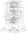
以下、本発明の実施形態を説明する。図1は本発明の第1実施形態に係る電池パック残量検知装置の構成図である。本発明の第1実施形態に係る電池パック残量検知装置は、電池パック11の放電電流Ioutを検出する放電電流検出手段12と、放電電流検出手段12で検出した放電電流Ioutを増幅する増幅器13と、電池パック11の充電電流Iinを検出する充電電流検出手段14と、演算部15と、記憶部16とからなる。演算部15及び記憶部16は、例えばマイコンで形成される。
Embodiments of the present invention will be described below. FIG. 1 is a configuration diagram of a battery pack remaining amount detection device according to a first embodiment of the present invention. The battery pack remaining amount detection device according to the first embodiment of the present invention includes a discharge
電池パック11は、電池セル17の充電を行う充電器18と電池セル17の放電を行う放電器19とからなる定電圧充放電回路を内蔵し、電池セル17の入力電圧Vin及び出力電圧Voutを一定に保つ。放電電流検出手段12で検出された電池パック11の放電電流Ioutは、増幅器13で増幅されて演算部15の第1残量演算手段20に入力される。増幅器13を設けているのは、放電電流検出手段12として抵抗素子が用いられるので、電池パック11の電力損失を小さくするために抵抗素子の抵抗値を小さくしているためである。つまり、抵抗素子の抵抗値が小さいので、検出電流を電圧に変換した値が小さいからである。
The
第1残量演算手段20では電池パック11の放電電流Ioutに基づいて電池パック11の残量を演算する。具体的には、放電電流Ioutを積分して放電量を演算し、記憶部16の第1残量記憶部21に記憶された第1残量から放電量を減算して電池パック11の残量を演算する。第1残量記憶部21には、第1残量として、後述の第2残量演算手段22で演算した充電後の電池パック11の残量が初期値として記憶されており、充電後の残量から放電量を減算して電池パック11の残量を演算し、第1残量記憶部21に更新記憶する。これにより、第1残量記憶部21には時々刻々変化する電池パック11の残量が記憶されている。
The first remaining amount calculating means 20 calculates the remaining amount of the
一方、充電電流検出手段14で検出された電池パック11の充電電流Iinは、演算部15の第2残量演算手段22に入力される。充電時には電池パック11の電力を消費しないので、充電電流検出手段14の抵抗素子を大きくできることから図1では増幅器を設けていない。充電電流検出手段14の抵抗素子を大きくすると計測精度を高くできる。また、増幅器を設けてもよく、その場合は、放電電流検出手段12で検出した放電電流Ioutを増幅する増幅器13よりも増幅率の小さい増幅器でよい。
On the other hand, the charging current Iin of the
第2残量演算手段22は、電池パック11の充電電流Iin及び記憶部16の充電電流プロファイル記憶部23に予め記憶された充電電流プロファイルに基づいて、電池パック11の充電開始時の電池パック11の残量を演算し第2残量記憶部24に記憶する。また、電池パック11の充電に伴って変化する充電電流Iin及び充電電流プロファイルの特性曲線に基づいて電池パック11の残量を演算し、第2残量記憶部24に第2残量として更新記憶する。これにより、第2残量記憶部24には充電開始時の電池パック11の残量、及び充電中の電池パック11の残量が記憶され、最終的に充電後の電池パック11の残量が記憶される。
The second remaining amount calculating means 22 is based on the charging current Iin of the
残量初期化手段25は、電池パック11の充電が終了したとき、第2残量演算手段22で演算された電池パック11の充電終了時の残量を当該電池パック11の残量とするものである。具体的には、残量初期化手段25は、電池パック11の充電が終了したときは、第2残量記憶部24に記憶されている第2残量を第1残量記憶部21に記憶させる。つまり、第1残量として、第2残量演算手段22で演算した充電後の電池パック11の残量が初期値として記憶される。なお、残量初期化手段25は必ずしも設ける必要はなく、電池パック11の充電が終了したときに、手動で第2残量記憶部24の第2残量を第1残量記憶部21に第1残量として記憶するようにしてもよい。
The remaining
次に、充電電流プロファイルについて説明する。充電電流プロファイルは、予め同種の電池パックを用いて、残量0→100%に充電するときの入力電流Iinの変化を求め、電池パック11の充電時の充電電流Iinと電池パック11の残量との関係を示した特性曲線で示されるファイルである。
Next, the charging current profile will be described. The charging current profile uses the same type of battery pack in advance to determine the change in the input current Iin when charging from 0 to 100% remaining, and the charging current Iin when charging the
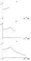
ここで、リチウムイオン電池の充電には、通常、定電流−定電圧充電が用いられる。図2は、リチウムイオン電池の充電特性を示すグラフである。図2に示すように、リチウムイオン電池の残量がゼロの状態からの充電の場合、最初は定電流充電であるので、リチウムイオン電池の電池端入力電流Iは一定であり電池端入力電圧Vが徐々に増加していく。そして、リチウムイオン電池の電池端入力電圧Vがある定められた値V0になると定電圧充電に移行し充電電流が徐々に減少していく。 Here, constant current-constant voltage charging is usually used for charging the lithium ion battery. FIG. 2 is a graph showing the charging characteristics of the lithium ion battery. As shown in FIG. 2, in the case of charging from a state where the remaining amount of the lithium ion battery is zero, since the constant current charging is initially performed, the battery end input current I of the lithium ion battery is constant and the battery end input voltage V Gradually increases. Then, when the battery terminal input voltage V of the lithium ion battery reaches a predetermined value V0, the charging current is gradually reduced by shifting to constant voltage charging.
一方、本発明の第1実施形態の電池パック11の充電の場合には、電池パック11が定電圧充放電回路を内蔵していることから、定電流−定電圧充電の制御は定電圧充放電回路の充電器18が行う。図3は第1実施形態の電池パック11の充電特性を示すグラフである。図3に示すように、電池パック11の入力電圧Vinには電圧変化は現れないが、入力電力は電池パック11の内外で変わらないため、充電器18の損失を無視すると入力電流Iinの変化として現れる。すなわち、電池パック11の電圧セル17の定電流充電時には電池パック11の入力電流Iinは増加し、定電圧充電移行後は入力電流Iinは減少する。
On the other hand, in the case of charging the
そこで、予め同種の電池パックを用いて、残量0→100%に充電するときの入力電流Iinの変化を充電電流プロファイルとして充電電流プロファイル記憶部23に保存しておく。実際に電池パック11を充放電する際には、電流の絶対値と増減方向を充電電流プロファイルと比較することにより、電池パック11の残量を検知する。
Therefore, using the same type of battery pack, a change in the input current Iin when the remaining amount is charged from 0 to 100% is stored in the charging current
図4は充電電流プロファイルの説明図である。縦軸は充電時の充電電流Iin、横軸は電池パック11の残量であり、充電電流プロファイルは電池パック11の充電時の特性曲線を示している。図4に示すように、電池パック11の残量が0%のときの充電電流IinはI0であり、電池パック11の残量が100%のときの充電電流IinはI100である。そして、電池パック11の電池セル17が定電流充電のときは電池パック11の充電電流Iinは単調増加特性となり、電池パック11の電池セル17が定電圧充電に切り替わると充電電流Iinは単調減少特性となる。この定電流充電から定電圧充電への切替点が変曲点Hである。
FIG. 4 is an explanatory diagram of a charging current profile. The vertical axis represents the charging current Iin during charging, the horizontal axis represents the remaining amount of the
いま、電池パック11の充電開始時の充電電流IinがI1であったとする。この場合、充電電流プロファイルの特性曲線には変曲点Hがあるので、充電電流I1に対応する残量は、変曲点Hを挟んだKa点(a1%)、Kb点(b1%)の2箇所となり、充電開始時の電池パックの残量を判定することができない。そこで、第2残量演算手段22は、充電開始時から所定の時間間隔で複数時点の充電電流Iinを取得し、充電電流Iinの増減方向を判定する。充電電流Iinが増加方向にあるときは変曲点Hより手前(定電流充電のとき)であり、充電電流Iinが減少方向にあるときは変曲点Hより先(定電圧充電のとき)である。例えば、充電開始時点t1で充電電流I1を取得し、次の時点t2で充電電流I2を取得したとすると、充電開始時の電池パックの残量はa1%(Ka点)であり、充電開始時点t1で充電電流I1を取得し、次の時点t2で充電電流I3を取得したとすると、充電開始時の電池パックの残量はb1%(Kb点)である。
Assume that the charging current Iin at the start of charging the
このように、第2残量演算手段22は、充電電流Iinの増減方向及び充電電流Iinの電流値に基づいて電池パック11の充電開始時の電池パック11の残量を演算する。また、電池パック11の充電に伴って変化する充電電流Iin及び充電電流プロファイルの特性曲線に基づいて電池パック11の残量を第2残量として演算する。例えば、所定間隔で取得した時点txの充電電流Ixにより電池パック11の残量を求め、記憶部16の第2残量記憶部24に更新記憶する。通常は、満充電(100%)まで充電するが、場合によっては満充電(100%)前のX%で充電を終了することもある。そのときは、第2残量記憶部24には残量としてX%が記憶されることになる。
As described above, the second remaining amount calculating means 22 calculates the remaining amount of the
本発明の第1実施形態によれば、第1残量演算手段21で放電時の電池パックの残量を放電電流Ioutを積分して放電量を演算し、第1残量記憶部21に記憶された第1残量から放電量を減算して電池パック11の残量を演算するので、使用後の電池パックの残量を求めることができる。
According to the first embodiment of the present invention, the remaining amount of the battery pack at the time of discharge is integrated by the discharge current Iout by the first remaining amount calculating means 21 to calculate the discharge amount and stored in the first remaining
また、使用後の電池パックの充電開始時に、第2残量演算手段22で充電開始時の電池パック11の残量を予め定めた充電電流プロファイルに基づき演算するので、第2残量演算手段22でも使用後の電池パックの残量を求めることができ、第1残量演算手段21で求めた使用後の電池パックの残量と比較することにより第1残量演算手段21での演算誤差を検知することができる。
In addition, when the charging of the battery pack after use is started, the second remaining
また、第2残量演算手段22で充電電流プロファイルに充電後の電池パックの残量を求め、求めた充電後の電池パックの残量を、当該電池パックの初期値として第1残量記憶部21に記憶するので、第1残量演算手段20での演算誤差を解消できる。 Further, the second remaining amount calculating means 22 obtains the remaining amount of the battery pack after charging in the charging current profile, and uses the obtained remaining amount of the charged battery pack as the initial value of the battery pack. Therefore, the calculation error in the first remaining amount calculating means 20 can be eliminated.
特に、本発明の第1実施形態に係る電池パック残量検知装置を搭載した電池パックが、人間が入ることができない箇所の作業や調査を行う遠隔操作ロボットに搭載される場合には、電池パックの残量が少なくなると充電可能箇所まで引き戻す必要があることから、第1残量演算手段20で演算した第1残量を遠隔操作部に送信するようにして電池パック11の残量を監視している。従って、電池パックの充電開始時に第2残量演算手段22で充電開始時の電池パック11の残量を演算し、第1残量演算手段21で求めた電池パックの残量と比較し、第1残量演算手段21の演算誤差を検知することは、遠隔操作ロボットの作業や調査のためにも重要なことである。演算誤差が大きい電池パックを搭載した遠隔操作ロボットの場合には、早めに充電可能箇所まで引き戻すことができるので、残量不足で遠隔操作ロボットが走行不能になることを避けられる。
In particular, when the battery pack equipped with the battery pack remaining amount detection device according to the first embodiment of the present invention is mounted on a remote operation robot that performs work or investigation of a place where a human cannot enter, the battery pack When the remaining amount of the battery pack becomes small, it is necessary to pull back to the rechargeable portion. Therefore, the remaining amount of the
次に、本発明の第2実施形態を説明する。図5は本発明の第2実施形態に係る電池パック残量検知装置の構成図である。この第2実施形態は、図1に示した第1実施形態に対し、記憶部16に充放電サイクル数記憶部26を設け、この充放電サイクル数記憶部26に電池パック11の充放電のサイクル数を記憶するとともに、記憶部16の充電電流プロファイル記憶部23に電池パック11の充放電のサイクル数に応じた複数の充電電流プロファイルを予め記憶しておき、第2残量演算手段22は、電池パック11の充放電のサイクル数に応じて充電電流プロファイルを選択して電池パック11の残量を演算するようにしたものである。図1と同一要素には、同一符号を付し重複する説明は省略する。
Next, a second embodiment of the present invention will be described. FIG. 5 is a configuration diagram of a battery pack remaining amount detection device according to the second embodiment of the present invention. The second embodiment is different from the first embodiment shown in FIG. 1 in that the
一般に、電池パック11の電池セル17は充放電サイクルを繰り返すことにより劣化する。電池パック11の劣化が進むと、充電電流プロファイルは定電流充電時間が短くなる特性となる。図6は充放電サイクルをパラメータとした充電電流プロファイルの説明図である。図6の曲線S1は新品の電池パック11の充電電流プロファイルの特性曲線であり、図6の曲線S2は充放電サイクルが多い劣化した電池パック11の充電電流プロファイルの特性曲線である。
Generally, the
図6に示すように、電池パック11の劣化が進むと定電圧充電時間が長くなることから、定電流充電から定電圧充電への切替点である変曲点がH1からH2に移動する。新品の電池パック11の充電電流プロファイルの特性曲線では領域E1に示すように定電圧充電時の電流変化が大きく、充放電サイクル数の多い電池パック11の充電電流プロファイルの特性曲線では領域E2に示すように定電圧充電時の電流変化が小さくなる。これにより、充放電サイクル数の多い電池パック11ではトータルとして充電量が減少するという傾向となる。従って、定電流充電から定電圧充電に移行するポイントでの残量が実際は少ないなど、初期の充電電流プロファイル(新品の電池パックの充電電流プロファイル)では残量を正確に表現することができなくなる。
As shown in FIG. 6, the constant voltage charging time becomes longer as the deterioration of the
そこで、本発明の第2実施形態では、例えば、事前に同種の電池パックで充放電サイクルを繰り返して、劣化後の充電電流プロファイルも複数取得しておき、充電電流プロファイル記憶部23に記憶しておく。また、充放電サイクル数記憶部26には、電池パック11の充電回数が充放電サイクル数として記憶される。この充放電サイクル数は充放電量を充電回数に換算した値である。これは、「充電量(蓄電量)0%→充電量(蓄電量)100%→充電量(蓄電量)0%」のサイクルを繰り返すのと、「充電量(蓄電量)60→充電量(蓄電量)80%→充電量(蓄電量)60」のサイクルを繰り返すのとでは、同じ1サイクルであっても、電池パック11の劣化の度合いは変わってくるからである。そこで、例えば、充電量(蓄電量)100%の電池パック11を充電量(蓄電量)0%まで使用(放電)し、充電量(蓄電量)100%に充電する場合を充放電サイクル数「1」とする。従って、充電量(蓄電量)80%の電池パック11を充電量(蓄電量)60%まで使用し、充電量(蓄電量)80%まで充電する場合は、充放電サイクル数を0.2サイクルと換算して更新記憶する。また、充電量(蓄電量)80%の電池パック11を充電量(蓄電量)60%まで使用し、充電量(蓄電量)100%に充電する場合は、充放電サイクル数を0.3サイクルと換算して更新記憶する。
Therefore, in the second embodiment of the present invention, for example, a charge / discharge cycle is repeated in advance with the same type of battery pack, and a plurality of deteriorated charge current profiles are acquired and stored in the charge current
電池パックの充電回数は、残量初期化手段25により第2残量演算手段22で演算された電池パック11の充電終了時の残量を第1残量記憶部21に記憶させる際に、充放電サイクル数記憶部26の充放電サイクル数に加算して更新記憶する。
The number of times the battery pack is charged is determined when the remaining amount at the end of charging of the
第2残量演算手段22で、どの充電電流プロファイルを選択するかは、充放電サイクル数記憶部26に記憶された充放電サイクルに基づいて判断する。充放電サイクル数が少ないときは、充放電サイクル数の少ない充電電流プロファイルを選択し、充放電サイクル数が多いときは、充放電サイクル数の多い充電電流プロファイルを選択する。これにより、電池パック11がまだ新しく定電圧充電時の電流変化が大きい場合には充放電サイクル数の少ない充電電流プロファイルが選択され、電池が劣化して定電圧充電時の電流変化が鈍くなった場合には充放電サイクル数の多い充電電流プロファイルが選択される。このようにして、充放電サイクル数に対する残量補正を充電時に行うことができる。以上の説明では、充放電サイクル数に応じて充電電流プロファイルを選択するようにしたが、定電圧充電時の電流変化によって充電電流プロファイルを選択するようにしてもよい。
Which charge current profile is selected by the second remaining amount calculating means 22 is determined based on the charge / discharge cycle stored in the charge / discharge cycle
本発明の第2実施形態によれば、第1実施形態の効果に加え、電池パック11の充放電のサイクル数に応じて適切な充電電流プロファイルを選択して電池パック11の残量を演算できるので、電池パック11の劣化の度合いに応じて電池パック11の残量をより正確に演算できる。
According to the second embodiment of the present invention, in addition to the effects of the first embodiment, the remaining charge of the
次に、本発明の第3実施形態を説明する。図7は本発明の第3実施形態に係る電池パック残量検知装置の構成図である。この第3実施形態は、図5に示した第2実施形態に対し、電池パック11の充電時に充電電流検出手段14で検出された充電電流Iinの軌跡に基づいて充電電流プロファイルを作成する充電電流プロファイル作成手段27を追加して設けたものである。図5と同一要素には同一符号を付し重複する説明は省略する。
Next, a third embodiment of the present invention will be described. FIG. 7 is a configuration diagram of a battery pack remaining amount detection device according to the third embodiment of the present invention. This third embodiment is different from the second embodiment shown in FIG. 5 in that the charging current profile is created based on the locus of the charging current Iin detected by the charging current detecting
充電電流プロファイル作成手段27は、電池パック11の充電の際に充電電流検出手段14で検出された充電電流Iinの軌跡に基づいて充電電流プロファイルを作成し、充電電流プロファイル記憶部23に記憶する。充電電流プロファイル作成手段27は、充電の度に起動してもよいが、充電の度に起動すると充電電流プロファイルが増加するので、所定回数毎に起動するようにしてもよい。
The charging current
この充電電流プロファイル作成手段27で作成された充電電流プロファイルは同種の別の電池パック11に適用される。すなわち、第2実施形態で事前に同種の電池パックで充放電サイクルを繰り返して劣化後の充電電流プロファイルを複数取得することに代えて、実際の電池パック11の運用で充電電流プロファイル作成手段27により充電電流プロファイルを作成する。
The charging current profile created by the charging current profile creating means 27 is applied to another
図8は充電電流プロファイル作成手段27による充電電流プロファイルの作成の説明図である。図8(a)、(b)、(c)に示すように、充電電流プロファイル作成手段27は、充電開始時から所定の時間間隔で複数時点の充電電流Iinを取得し充電電流Iinの軌跡を描いていく。この場合、横軸は残量を示しているが、充電時には時間の経過とともに残量も変化するので、充電電流Iinの軌跡に基づいて当該電池パック11の充電電流プロファイルを作成できる。
FIG. 8 is an explanatory diagram for creating a charging current profile by the charging current
本発明の第3実施形態によれば、事前に同種の電池パックで充放電サイクルを繰り返して劣化後の充電電流プロファイルを複数取得しなくても、実際の電池パック11の運用で充電電流プロファイル作成手段27により充電電流プロファイルを作成するで、例えば、遠隔操作ロボットに搭載した電池パック11に即した充電電流プロファイルを作成できる。以上の説明では、図5に示した第2実施形態に対し、充電電流プロファイル作成手段27を追加して設けた場合について説明したが、図1に示した第1実施形態に対し、充電電流プロファイル作成手段27を追加して設けるようにしてもよい。
According to the third embodiment of the present invention, it is possible to create a charging current profile in actual operation of the
次に、本発明の第4実施形態を説明する。図9は本発明の第3実施形態に係る電池パック残量検知装置の構成図である。この第4実施形態は、図7に示した第3実施形態に対し、電池パック11がベース負荷のみに電流を供給しているときのベース負荷電流を予め記憶したベース負荷電流記憶部28と、電池パック11がベース負荷のみに電流を供給しているとき、その放電電流Ioutが予めベース負荷電流記憶部28も記憶したベース負荷電流と一致するように増幅器13を調整する残量補正手段29とを追加して設けたものである。図7と同一要素には同一符号を付し重複する説明は省略する。
Next, a fourth embodiment of the present invention will be described. FIG. 9 is a configuration diagram of a battery pack remaining amount detection device according to the third embodiment of the present invention. The fourth embodiment is different from the third embodiment shown in FIG. 7 in that the base load
電池パック11の放電時は、電池パックの電池セル17を長時間の使用を持続させるために損失を低く抑えることが重要である。このことから、放電電流検出手段12の検出抵抗は小さい値としたいが、抵抗値を小さくすると演算部15のアナログ入力分解能に対して十分な精度の値を得ることができない。そこで、前述したように増幅器13を設けている。放電電流検出手段12の検出信号の増幅時には、オフセットやドリフトによる誤差が生じるのが一般的である。
When the
遠隔操作ロボットに搭載される電池パック11は、遠隔操作ロボットの走行用車輪を駆動する電動機や作業用機器を駆動する電動機、遠隔操作ロボットの駆動制御を行う制御装置(例えば、マイコン)や電子機器(例えば、カメラ、検出器)などに電力を供給する。電動機は消費電力の変動が大きい負荷であり、制御装置や電子機器は消費電力の変動の少ない負荷である。遠隔操作ロボットを走行させたり、作業用機器を駆動したりしているときは、電動機が起動されているので電池パック11からの放電電流は大きくなる。一方、遠隔操作ロボットの走行及び作業用機器の駆動を停止すると、電動機の消費電力はゼロとなる。これに対し、制御装置や電子機器は、電動機が停止していても制御や監視のために動作状態を維持しなければならないので、定常的に電力を消費しており消費電力の変動の少ない負荷である。
The
図10は遠隔操作ロボットに搭載される電池パックの放電電流Ioutの時間変化の一例を示すグラフである。遠隔操作ロボットに搭載される電池パック11は、遠隔操作ロボットの消費電力に応じて放電電流Ioutが変化する。時点t0〜時点t1の期間T1、時点t2〜時点t3の期間T2、時点t4〜時点t5の期間T3においては、制御装置や電子機器が定常的に電力を消費しており、この消費電力はベース負荷電流に相当する。時点t1〜時点t2の期間、時点t3〜時点t4の期間、時点t5〜の期間は、ベース負荷電流に加え、電動機が駆動されている期間である。
FIG. 10 is a graph showing an example of the change over time of the discharge current Iout of the battery pack mounted on the remote control robot. In the
そこで、電池パック11が制御装置や電子機器などのベース負荷の消費電力に着目し、ベース負荷の消費電力に対応するベース負荷電流を予め測定しておき、ベース負荷電流記憶部28に記憶しておく。そして、残量補正手段29は、制御装置が消費電力の変動の大きい負荷(例えば、電動機)を駆動していないときの放電電流Ioutとベース負荷電流記憶部28に記憶されたベース負荷電流とを比較し、電池パック11がベース負荷のみに電流を供給しているときの放電電流Ioutが予めベース負荷電流と一致するように増幅器13の増幅率を調整する。これにより、放電電流検出手段12の検出信号の誤差を補正し、第1残量演算手段20で演算された電池パックの残量(第1残量)をより正確なものとすることができる。
Therefore, the
以上の説明では、図7に示した第3実施形態に対し、ベース負荷電流記憶部28と残量補正手段29とを追加して設けた場合について説明したが、図1に示した第1実施形態、図5に示した第2実施形態に対し、ベース負荷電流記憶部28と残量補正手段29とを追加して設けるようにしてもよい。
In the above description, the case where the base load
また、以上の各々の実施形態において、電池パック11に残量検知用の演算部15及び記憶部16を設けるようにしたが、遠隔操作ロボットに搭載される電池パックの場合には、遠隔操作ロボットを監視制御する監視制御装置(マイコン)に形成してもよい。また、遠隔操作ロボットに搭載されたマイコンに代えて、遠隔操作ロボットを遠隔操作する遠隔操作部に設けるようにしてもよい。
Further, in each of the above embodiments, the
以上、本発明のいくつかの実施形態を説明したが、これらの実施形態は、例として提示したものであり、発明の範囲を限定することは意図していない。これら新規な実施形態は、その他の様々な形態で実施されることが可能であり、発明の要旨を逸脱しない範囲で、種々の省略、置き換え、変更を行うことができる。これら実施形態やその変形は、発明の範囲や要旨に含まれるとともに、特許請求の範囲に記載された発明とその均等の範囲に含まれる。 As mentioned above, although some embodiment of this invention was described, these embodiment is shown as an example and is not intending limiting the range of invention. These novel embodiments can be implemented in various other forms, and various omissions, replacements, and changes can be made without departing from the scope of the invention. These embodiments and modifications thereof are included in the scope and gist of the invention, and are included in the invention described in the claims and the equivalents thereof.
11…電池パック、12…放電電流検出手段、13…増幅器、14…充電電流検出手段、15…演算部、16…記憶部、17…電池セル、18…充電器、19…放電器、20…第1残量演算手段、21…第1残量記憶部、22…第2残量演算手段、23…充電電流プロファイル記憶部、24…第2残量記憶部、25…残量初期化手段、26…充放電サイクル数記憶部、27…充電電流プロファイル作成手段、28…ベース負荷電流記憶部、29…残量補正手段
DESCRIPTION OF
Claims (5)
前記電池パックの放電時に前記放電電流検出手段で検出された放電電流に基づいて前記電池パックの残量を演算する第1残量演算手段と、
前記電池パックの充電時の充電電流と前記電池パックの残量との関係を示した特性曲線を予め充電電流プロファイルとして記憶した記憶部と、
前記電池パックの充電時に前記電池パックの充電電流を検出する充電電流検出手段と、
前記電池パックの充電時に前記充電電流検出手段で検出された充電電流の増減方向及び前記充電電流の電流値に基づいて前記電池パックの充電開始時の電池パックの残量を演算するとともに、前記電池パックの充電に伴って変化する充電電流及び充電電流プロファイルの特性曲線に基づいて前記電池パックの残量を演算する第2残量演算手段とを備え、前記第1残量演算手段は前記第2残量演算手段で演算した充電後の電池パックの残量から前記第1残量演算手段で放電電流に基づき演算した放電量を減算して電池パックの残量を演算することを特徴とする電池パック残量検知装置。 A discharge current detecting means for detecting a discharge current of the battery pack when the battery pack has a constant input / output voltage;
First remaining amount calculating means for calculating the remaining amount of the battery pack based on the discharge current detected by the discharge current detecting means when the battery pack is discharged;
A storage unit storing a characteristic curve indicating a relationship between a charging current at the time of charging the battery pack and a remaining amount of the battery pack in advance as a charging current profile;
Charging current detecting means for detecting a charging current of the battery pack when charging the battery pack;
The battery pack calculates the remaining amount of the battery pack at the start of charging the battery pack based on the charging current increase / decrease direction detected by the charging current detection means and the current value of the charging current when the battery pack is charged. Second remaining amount calculating means for calculating the remaining amount of the battery pack based on a charging current that changes as the pack is charged and a characteristic curve of the charging current profile, wherein the first remaining amount calculating means includes the second remaining amount calculating means. A battery characterized in that the remaining amount of the battery pack is calculated by subtracting the amount of discharge calculated based on the discharge current by the first remaining amount calculating means from the remaining amount of the battery pack after charging calculated by the remaining amount calculating means. Pack remaining amount detection device.
Priority Applications (1)
| Application Number | Priority Date | Filing Date | Title |
|---|---|---|---|
| JP2014036343A JP6233094B2 (en) | 2014-02-27 | 2014-02-27 | Battery pack remaining amount detection device |
Applications Claiming Priority (1)
| Application Number | Priority Date | Filing Date | Title |
|---|---|---|---|
| JP2014036343A JP6233094B2 (en) | 2014-02-27 | 2014-02-27 | Battery pack remaining amount detection device |
Publications (2)
| Publication Number | Publication Date |
|---|---|
| JP2015161562A JP2015161562A (en) | 2015-09-07 |
| JP6233094B2 true JP6233094B2 (en) | 2017-11-22 |
Family
ID=54184746
Family Applications (1)
| Application Number | Title | Priority Date | Filing Date |
|---|---|---|---|
| JP2014036343A Active JP6233094B2 (en) | 2014-02-27 | 2014-02-27 | Battery pack remaining amount detection device |
Country Status (1)
| Country | Link |
|---|---|
| JP (1) | JP6233094B2 (en) |
Family Cites Families (4)
| Publication number | Priority date | Publication date | Assignee | Title |
|---|---|---|---|---|
| JP4168648B2 (en) * | 2001-04-03 | 2008-10-22 | 富士電機デバイステクノロジー株式会社 | Battery level measuring device |
| JP4782663B2 (en) * | 2006-11-29 | 2011-09-28 | パナソニック株式会社 | Charging system, charging device, and battery pack |
| JP2008295169A (en) * | 2007-05-23 | 2008-12-04 | Canon Inc | Battery pack, charger and electronic apparatus |
| JP5491047B2 (en) * | 2009-03-05 | 2014-05-14 | ソニーモバイルコミュニケーションズ, エービー | Terminal device, battery remaining amount display method and program |
-
2014
- 2014-02-27 JP JP2014036343A patent/JP6233094B2/en active Active
Also Published As
| Publication number | Publication date |
|---|---|
| JP2015161562A (en) | 2015-09-07 |
Similar Documents
| Publication | Publication Date | Title |
|---|---|---|
| EP2568569B1 (en) | Charger | |
| JP6151163B2 (en) | Battery state calculation device and battery state calculation method | |
| JP6763376B2 (en) | Battery control device, power storage system, control method and computer-readable medium | |
| US20140278170A1 (en) | State of charge (soc) display for rechargeable battery | |
| JP2013083612A (en) | Battery state measurement method and battery state measurement apparatus | |
| CA2899239A1 (en) | Method for determining a state of charge and remaining operation life of a battery | |
| US20120158338A1 (en) | Battery management system and battery pack including battery management system | |
| US9077197B2 (en) | Battery residual amount measurement system, computer-readable medium storing battery residual amount measurement program, and battery residual amount measurement method | |
| JP2012185124A (en) | State-of-charge estimation device, state-of-charge estimation method, and program | |
| US20120153960A1 (en) | Negative Peak Voltage Detection for Enhanced FuelGauge Empty Voltage Prediction | |
| TWI528043B (en) | Battery SOC/SOH estimation circuit | |
| WO2016199455A1 (en) | Storage battery control device | |
| JP5084394B2 (en) | How to calculate the remaining battery capacity | |
| JP5620423B2 (en) | Electronic device and battery charging method for electronic device | |
| JP2005195388A (en) | Instrument for measuring residual level of battery | |
| JP6164147B2 (en) | Battery control system and control method thereof | |
| JP2016065844A (en) | Battery system control apparatus and control method of battery system | |
| JP6233094B2 (en) | Battery pack remaining amount detection device | |
| JP5523516B2 (en) | Charge / discharge control device | |
| WO2013038366A3 (en) | Circuit for a small electric appliance with an accumulator and method for measuring a charging current | |
| JP5480434B1 (en) | Capacitor power supply device, voltage monitoring device, voltage monitoring method, and method of manufacturing capacitor power supply device | |
| JP4660367B2 (en) | Rechargeable battery remaining capacity detection method | |
| JP2007322353A (en) | Battery capacity determining device, method, and battery pack using the same | |
| JP2007267499A (en) | Charger, charging system and electric apparatus | |
| EP3602724B1 (en) | Controlling a battery charge level |
Legal Events
| Date | Code | Title | Description |
|---|---|---|---|
| A621 | Written request for application examination |
Free format text: JAPANESE INTERMEDIATE CODE: A621 Effective date: 20170112 |
|
| A977 | Report on retrieval |
Free format text: JAPANESE INTERMEDIATE CODE: A971007 Effective date: 20170912 |
|
| TRDD | Decision of grant or rejection written | ||
| A01 | Written decision to grant a patent or to grant a registration (utility model) |
Free format text: JAPANESE INTERMEDIATE CODE: A01 Effective date: 20170926 |
|
| A61 | First payment of annual fees (during grant procedure) |
Free format text: JAPANESE INTERMEDIATE CODE: A61 Effective date: 20171009 |
|
| R150 | Certificate of patent or registration of utility model |
Ref document number: 6233094 Country of ref document: JP Free format text: JAPANESE INTERMEDIATE CODE: R150 |