JP6233062B2 - Liquid supply unit - Google Patents

Liquid supply unit Download PDF

Info

Publication number
JP6233062B2
JP6233062B2 JP2014015767A JP2014015767A JP6233062B2 JP 6233062 B2 JP6233062 B2 JP 6233062B2 JP 2014015767 A JP2014015767 A JP 2014015767A JP 2014015767 A JP2014015767 A JP 2014015767A JP 6233062 B2 JP6233062 B2 JP 6233062B2
Authority
JP
Japan
Prior art keywords
lid
wall
cartridge
housing
liquid
Prior art date
Legal status (The legal status is an assumption and is not a legal conclusion. Google has not performed a legal analysis and makes no representation as to the accuracy of the status listed.)
Active
Application number
JP2014015767A
Other languages
Japanese (ja)
Other versions
JP2015139986A (en
Inventor
瞬 大屋
瞬 大屋
小林 淳
淳 小林
忠弘 水谷
忠弘 水谷
Current Assignee (The listed assignees may be inaccurate. Google has not performed a legal analysis and makes no representation or warranty as to the accuracy of the list.)
Seiko Epson Corp
Original Assignee
Seiko Epson Corp
Priority date (The priority date is an assumption and is not a legal conclusion. Google has not performed a legal analysis and makes no representation as to the accuracy of the date listed.)
Filing date
Publication date
Application filed by Seiko Epson Corp filed Critical Seiko Epson Corp
Priority to JP2014015767A priority Critical patent/JP6233062B2/en
Priority to CA2932434A priority patent/CA2932434C/en
Priority to RU2016123602A priority patent/RU2660070C1/en
Priority to AU2014368304A priority patent/AU2014368304B2/en
Priority to PCT/JP2014/006136 priority patent/WO2015093008A1/en
Priority to PCT/JP2014/006167 priority patent/WO2015093012A1/en
Priority to CA2932696A priority patent/CA2932696C/en
Priority to RU2016123600A priority patent/RU2645206C2/en
Priority to PCT/JP2014/006221 priority patent/WO2015093027A1/en
Priority to AU2014368232A priority patent/AU2014368232B2/en
Priority to CN201410770713.6A priority patent/CN104723683B/en
Priority to CN201420790410.6U priority patent/CN204506139U/en
Priority to CN201410773179.4A priority patent/CN104723684B/en
Priority to BR112016014143-1A priority patent/BR112016014143A2/en
Priority to CN201710561409.4A priority patent/CN107297957B/en
Priority to CN201710971238.2A priority patent/CN107672316A/en
Priority to PCT/JP2014/006222 priority patent/WO2015093028A1/en
Priority to PCT/JP2014/006187 priority patent/WO2015093016A1/en
Priority to CN201420788209.4U priority patent/CN204472115U/en
Priority to PCT/JP2014/006218 priority patent/WO2015093024A1/en
Priority to CN201410776917.0A priority patent/CN104723685B/en
Priority to CN201711306297.4A priority patent/CN107891670B/en
Priority to CN201410778150.5A priority patent/CN104723686B/en
Priority to CN201420795684.4U priority patent/CN204605190U/en
Priority to CN201420797072.9U priority patent/CN204566928U/en
Priority to ES14198198T priority patent/ES2746323T3/en
Priority to ES14198200.9T priority patent/ES2691520T3/en
Priority to ES14198197T priority patent/ES2704093T3/en
Priority to EP14198195.1A priority patent/EP2886346B1/en
Priority to CN201710876901.0A priority patent/CN107521235B/en
Priority to PL14198199T priority patent/PL2886349T3/en
Priority to ES14198199T priority patent/ES2740074T3/en
Priority to EP14198200.9A priority patent/EP2886350B1/en
Priority to EP14198197.7A priority patent/EP2886347B1/en
Priority to CN201420797761.XU priority patent/CN204605191U/en
Priority to ES14198202T priority patent/ES2733105T3/en
Priority to EP14198198.5A priority patent/EP2886348B8/en
Priority to CN201410779761.1A priority patent/CN104723687B/en
Priority to EP14198199.3A priority patent/EP2886349B1/en
Priority to EP14198202.5A priority patent/EP2886351B1/en
Priority to EP19176167.5A priority patent/EP3549773A1/en
Priority to US14/573,192 priority patent/US9511594B2/en
Priority to CN201410784691.9A priority patent/CN104723688B/en
Priority to TW103144169A priority patent/TWI638723B/en
Priority to CN201420802342.0U priority patent/CN204605192U/en
Priority to TW103144176A priority patent/TWI643762B/en
Priority to US14/573,275 priority patent/US9321272B2/en
Priority to TW103144165A priority patent/TWI636892B/en
Priority to US14/573,128 priority patent/US9233546B2/en
Priority to US14/573,516 priority patent/US9233547B2/en
Priority to TW103144166A priority patent/TWI647121B/en
Priority to US14/573,053 priority patent/US9266340B2/en
Priority to US14/573,424 priority patent/US9844945B2/en
Priority to TW103144167A priority patent/TW201536577A/en
Priority to TW103144164A priority patent/TW201536574A/en
Publication of JP2015139986A publication Critical patent/JP2015139986A/en
Priority to US14/878,529 priority patent/US9346277B2/en
Priority to US14/964,976 priority patent/US9682566B2/en
Priority to US14/964,929 priority patent/US9682565B2/en
Priority to US15/134,230 priority patent/US9579900B2/en
Priority to US15/147,101 priority patent/US9694588B2/en
Priority to US15/430,987 priority patent/US10220627B2/en
Priority to US15/717,654 priority patent/US10220628B2/en
Application granted granted Critical
Publication of JP6233062B2 publication Critical patent/JP6233062B2/en
Active legal-status Critical Current
Anticipated expiration legal-status Critical

Links

Images

Description

本発明は、液体供給ユニットに関する。   The present invention relates to a liquid supply unit.

液体を液体噴射装置に供給可能な液体供給ユニットとしては、従来から、液体噴射装置の一例であるプリンターにインクを供給するインクカートリッジ(単に「カートリッジ」ともいう。)が知られている。このカートリッジは、液体としてのインクを収容するための凹形状の液体収容部を筐体で形成し、当該筐体に蓋を固定した状態で、インクを収容し、その収容したインクをプリンターに供給する。   As a liquid supply unit capable of supplying liquid to a liquid ejecting apparatus, an ink cartridge (also simply referred to as “cartridge”) that supplies ink to a printer, which is an example of a liquid ejecting apparatus, has been conventionally known. This cartridge forms a concave liquid storage portion for storing ink as a liquid in a casing, stores ink in a state where a lid is fixed to the casing, and supplies the stored ink to the printer. To do.

こうしたカートリッジでは、収容する色情報や残収容量等の各種情報をプリンターに伝達する必要がある。このため、カートリッジの底壁から立ち上がった外周壁には、プリンターとの間で情報をやり取りするための回路基板が備え付けられる。この他、プリンターへのカートリッジの装着に際しての装着姿勢維持のため、カートリッジの底壁から立ち上がった外周壁に係合レバー等の係合部材を備え付けることもなされている。上記した回路基板や係合部材は、カートリッジ外周壁の外側に位置することから、カートリッジの蓋の一部部位をカートリッジ外側まで張り出して、これら回路基板や係合部材を保護する手法が提案されている(例えば、特許文献1等)。   In such a cartridge, it is necessary to transmit various information such as the color information to be stored and the remaining storage amount to the printer. Therefore, a circuit board for exchanging information with the printer is provided on the outer peripheral wall rising from the bottom wall of the cartridge. In addition, in order to maintain the mounting posture when the cartridge is mounted on the printer, an engaging member such as an engaging lever is provided on the outer peripheral wall rising from the bottom wall of the cartridge. Since the circuit board and the engaging member described above are located outside the outer peripheral wall of the cartridge, a method for protecting the circuit board and the engaging member by extending a part of the lid of the cartridge to the outside of the cartridge has been proposed. (For example, Patent Document 1).

特開2004−1430号公報JP 2004-1430 A 米国特許8308279号公報U.S. Pat. No. 8,308,279

ところで、特許文献1では、カートリッジ外側まで張り出した蓋の一部部位(以下、適宜、蓋張出部と称する)での保護を行うに当たり、蓋張出部と回路基板との間に、蓋体および回路基板保持部とは別体の凸部を必要とする。よって、蓋張出部単独では保護機能を発揮できないことが危惧される。また、特許文献2では、蓋張出部での保護を行うに当たり、係合レバーを蓋張出部の近傍まで延ばさないと、蓋張出部単独での保護機能の実効性が期待できないことが危惧される。こうしたことから、カートリッジ外側まで張り出した蓋の一部部位単独での保護機能の実効性を高めることが要請されるに到った。また、端子を備えた液体供給ユニットや、当該ユニットから液体の供給を受ける液体噴射装置、液体供給ユニットと液体噴射装置とを備えたシステム等において、小型化、低コスト化、省資源化、製造の容易化、使い勝手の向上等が望まれている。   By the way, in Patent Document 1, when protection is performed on a part of the lid projecting to the outside of the cartridge (hereinafter referred to as a lid projecting portion as appropriate), a lid body is provided between the lid projecting portion and the circuit board. Further, a convex part separate from the circuit board holding part is required. Therefore, it is feared that the protective function cannot be exhibited by the lid overhanging part alone. Moreover, in patent document 2, when performing protection in a lid overhang | projection part, unless the engagement lever is extended to the vicinity of a lid overhang | projection part, the effectiveness of the protection function in a lid overhang | projection part cannot be expected. I'm worried. For these reasons, it has been requested to increase the effectiveness of the protective function of only a part of the lid projecting to the outside of the cartridge. In addition, in a liquid supply unit including a terminal, a liquid ejecting apparatus that receives liquid supply from the unit, a system including a liquid supply unit and a liquid ejecting apparatus, etc., downsizing, cost reduction, resource saving, manufacturing Ease of use and improved usability are desired.

本発明は、上述の課題の少なくとも一部を解決するためになされたものであり、以下の形態として実現することが可能である。   SUMMARY An advantage of some aspects of the invention is to solve at least a part of the problems described above, and the invention can be implemented as the following forms.

(1)本発明の一形態によれば、液体供給ユニットが提供される。この液体供給ユニットは、液体を液体噴射装置に供給可能な液体供給ユニットであって、凹部を有する筐体と、前記凹部を覆い前記筐体に固定される蓋と、前記筐体の外側壁に位置し、前記液体噴射装置の電極と電気的接触可能な端子とを備える。そして、前記蓋は、前記凹部を覆う蓋部と、前記端子が位置する前記外側壁の側において、前記蓋部から外方に延在する外方延在部とを有し、該外方延在部は、前記蓋から前記筐体に向かう第1方向に沿って前記蓋部から突出して延び、前記第1方向からの前記蓋の平面視において、前記端子と重なるまで延在する。この形態の液体供給ユニットは、凹部を覆う蓋部から外方に延在する外方延在部を、第1方向に沿って蓋部から突出して延ばすことで、第1方向において、端子の側に近づける。よって、この形態の液体供給ユニットによれば、外方延在部単独での端子の保護機能の実効性を高めることができる。また、凹部を覆う蓋部から第1方向に沿って外方延在部を突出して延ばすという簡易な構造により、外方延在部単独での端子の保護機能を得ることができる。 (1) According to an aspect of the present invention, a liquid supply unit is provided. The liquid supply unit is a liquid supply unit capable of supplying liquid to the liquid ejecting apparatus, and includes a housing having a recess, a lid that covers the recess and is fixed to the housing, and an outer wall of the housing. A terminal that is positioned and is in electrical contact with an electrode of the liquid ejecting apparatus. The lid includes a lid that covers the recess, and an outwardly extending portion that extends outward from the lid on the side of the outer wall where the terminal is located. The existing portion protrudes from the lid portion along the first direction from the lid toward the housing, and extends until it overlaps the terminal in a plan view of the lid from the first direction. In the liquid supply unit of this embodiment, the outward extending portion that extends outward from the lid portion that covers the concave portion extends and protrudes from the lid portion along the first direction, so that the terminal side in the first direction Move closer to Therefore, according to the liquid supply unit of this embodiment, it is possible to improve the effectiveness of the terminal protection function by the outward extending portion alone. In addition, the terminal protection function of the outward extending portion alone can be obtained by a simple structure in which the outward extending portion projects and extends along the first direction from the lid portion covering the recess.

(2)上記形態の液体供給ユニットにおいて、前記端子は回路基板に形成され、前記筐体は前記回路基板が固定される載置部を前記外側壁に有し、前記載置部には前記回路基板と重なる位置に開口が形成され、前記第1方向からの前記蓋の平面視において、前記蓋の前記外方延在部は前記開口と重なるようにしてもよい。こうすれば、次の利点がある。端子が形成された回路基板は、筐体の外側壁における載置部に、通常、熱カシメで固定される。この熱カシメの際に発生する熱は、基板載置部は元より筐体にも伝播させないことが望ましい。上記形態の液体供給ユニットによれば、載置部において回路基板と重なる位置に形成した開口により上記の熱を逃がすことができる上に、外方延在部をこの開口と重なるようにして、開口を外方延在部で塞ぐことができるので、開口への異物混入を防止できる。 (2) In the liquid supply unit of the above aspect, the terminal is formed on a circuit board, and the housing has a placement portion on the outer wall to which the circuit board is fixed, and the placement portion includes the circuit. An opening may be formed at a position overlapping the substrate, and the outwardly extending portion of the lid may overlap the opening in a plan view of the lid from the first direction. This has the following advantages. The circuit board on which the terminals are formed is usually fixed to the mounting portion on the outer wall of the casing with heat caulking. It is desirable that the heat generated during the caulking is not propagated from the substrate mounting portion to the housing. According to the liquid supply unit of the above aspect, the heat can be released by the opening formed at the position where the mounting portion overlaps the circuit board, and the outer extension portion overlaps with the opening, thereby opening the opening. Can be blocked by the outwardly extending portion, so that foreign matter can be prevented from entering the opening.

(3)上記形態の液体供給ユニットにおいて、前記蓋の前記外方延在部は前記載置部に係合する突出端を備えるようにできる。こうすれば、外方延在部により載置部を補強できるので、載置部への回路基板の固定に支障を来さない。 (3) In the liquid supply unit of the above aspect, the outwardly extending portion of the lid may include a protruding end that engages with the mounting portion. If it carries out like this, since a mounting part can be reinforced by an outward extension part, it will not interfere with fixation of a circuit board to a mounting part.

(4)上記いずれかの形態の液体供給ユニットにおいて、前記筐体は、前記凹部の底面をなして前記蓋の前記蓋部に対向する底壁と、該底壁から立ち上がり前記蓋の前記蓋部に交差する第1側壁と、前記底壁から立ち上がって前記蓋の前記蓋部に交差すると共に前記第1側壁に対向する第2側壁と、前記第1側壁の一方の端部と前記第2側壁の一方の端部の間において前記底壁から立ち上がって前記蓋の前記蓋部に交差する第1端壁と、前記第1側壁の他方の端部と前記第2側壁の他方の端部の間において前記底壁から立ち上がって前記蓋の前記蓋部に交差すると共に前記第1端壁と対向する第2端壁と、を有し、前記端子は、前記外側壁としての前記第1端壁に位置し、前記第2端壁から前記第1端壁に向かう第2方向において、前記蓋の前記外方延在部は前記端子より外方に突出しているようにできる。こうすれば、外方延在部単独での端子の保護機能の実効性を第2方向においても高めることができる。 (4) In the liquid supply unit according to any one of the above forms, the housing includes a bottom wall that forms a bottom surface of the recess and faces the lid portion of the lid, and rises from the bottom wall and the lid portion of the lid A second side wall that rises from the bottom wall and intersects the lid portion of the lid and faces the first side wall, one end of the first side wall, and the second side wall A first end wall that rises from the bottom wall and intersects the lid portion of the lid, and between the other end portion of the first side wall and the other end portion of the second side wall. And a second end wall that rises from the bottom wall and intersects the lid portion of the lid and faces the first end wall, and the terminal is provided on the first end wall as the outer wall. In the second direction from the second end wall to the first end wall, Kigaikata extending portion may be as projecting outward from the terminal. If it carries out like this, the effectiveness of the protection function of the terminal only in an outward extension part can be raised also in the 2nd direction.

(5)上記ずれかの形態の液体供給ユニットにおいて、前記蓋の前記外方延在部は前記液体噴射装置と係合可能な係合部を有するようにできる。こうすれば、外方延在部により液体噴射装置への係合機能も発揮できる。 (5) In the liquid supply unit in the above-described configuration, the outwardly extending portion of the lid may have an engaging portion that can engage with the liquid ejecting apparatus. In this case, the engagement function to the liquid ejecting apparatus can be exhibited by the outward extending portion.

(6)本発明の他の形態によれば、液体供給ユニットが提供される。この液体供給ユニットは、液体を液体噴射装置に供給可能な液体供給ユニットであって、凹部を有する筐体と、該筐体に固定されて前記凹部を覆う蓋と、前記筐体の外側壁に位置し、前記液体噴射装置と係合可能な係合部とを備える。そして、前記蓋は、前記凹部を覆う蓋部と、前記係合部が位置する前記外側壁の側において、前記蓋部から外方に延在する外方延在部とを有し、該外方延在部は、前記蓋から前記筐体に向かう第1方向に沿って前記蓋部から突出して延び、前記第1方向からの前記蓋の平面視において、前記係合部と重なるまで延在する。この形態の液体供給ユニットは、凹部を覆う蓋部から外方に延在する外方延在部を、第1方向に沿って蓋部から突出して延ばすことで、第1方向において、係合部の側に近づける。よって、この形態の液体供給ユニットによれば、外方延在部単独での係合部の保護機能の実効性を高めることができる。また、凹部を覆う蓋部から第1方向に沿って外方延在部を突出して延ばすという簡易な構造により、外方延在部単独での係合部の保護機能を得ることができる。 (6) According to another aspect of the present invention, a liquid supply unit is provided. The liquid supply unit is a liquid supply unit capable of supplying liquid to the liquid ejecting apparatus, and includes a casing having a recess, a lid fixed to the casing and covering the recess, and an outer wall of the casing. An engaging portion that is positioned and engageable with the liquid ejecting apparatus. The lid includes a lid that covers the recess, and an outwardly extending portion that extends outward from the lid on the outer wall side where the engaging portion is located. The direction extending portion extends from the lid along the first direction from the lid toward the housing, and extends until it overlaps the engagement portion in a plan view of the lid from the first direction. To do. The liquid supply unit according to this aspect has an engaging portion in the first direction by extending an outwardly extending portion extending outward from the lid portion covering the concave portion along the first direction. Move closer to the side. Therefore, according to the liquid supply unit of this embodiment, the effectiveness of the protection function of the engaging portion by the outward extending portion alone can be enhanced. Moreover, the protection function of the engaging part by the outward extension part alone can be obtained by a simple structure in which the outward extension part protrudes and extends along the first direction from the lid part covering the recess.

(7)上記の形態の液体供給ユニットにおいて、前記筐体は、前記凹部の底面をなして前記蓋の前記蓋部に対向する底壁と、該底壁から立ち上がり前記蓋の前記蓋部に交差する第1側壁と、前記底壁から立ち上がって前記蓋の前記蓋部に交差すると共に前記第1側壁に対向する第2側壁と、前記第1側壁の一方の端部と前記第2側壁の一方の端部の間において前記底壁から立ち上がって前記蓋の前記蓋部に交差する第1端壁と、前記第1側壁の他方の端部と前記第2側壁の他方の端部の間において前記底壁から立ち上がって前記蓋の前記蓋部に交差すると共に前記第1端壁と対向する第2端壁と、を有し、前記係合部は、前記外側壁としての前記第1端壁に位置し、前記第2端壁から前記第1端壁に向かう第2方向において、前記蓋の前記外方延在部は前記係合部より外方に突出している。こうすれば、外方延在部単独での係合部の保護機能の実効性を第2方向においても高めることができる。 (7) In the liquid supply unit according to the above aspect, the casing includes a bottom wall that forms a bottom surface of the recess and faces the lid portion of the lid, and rises from the bottom wall and intersects the lid portion of the lid. A first side wall that rises from the bottom wall, intersects the lid portion of the lid and faces the first side wall, one end of the first side wall, and one of the second side walls A first end wall that rises from the bottom wall and intersects the lid portion of the lid, between the other end portion of the first side wall and the other end portion of the second side wall. A second end wall that rises from the bottom wall and intersects the lid portion of the lid and faces the first end wall, and the engaging portion is provided on the first end wall as the outer wall. Positioned in a second direction from the second end wall to the first end wall, Extending portion protrudes outward from the engagement portion. If it carries out like this, the effectiveness of the protection function of the engaging part only by an outward extension part can be improved also in a 2nd direction.

上述した本発明の各形態の有する複数の構成要素は全てが必須のものではなく、上述の課題の一部または全部を解決するため、あるいは、本明細書に記載された効果の一部または全部を達成するために、適宜、前記複数の構成要素の一部の構成要素について、その変更、削除、新たな構成要素との差し替え、限定内容の一部削除を行うことが可能である。また、上述の課題の一部または全部を解決するため、あるいは、本明細書に記載された効果の一部または全部を達成するために、上述した本発明の一形態に含まれる技術的特徴の一部または全部を上述した本発明の他の形態に含まれる技術的特徴の一部または全部と組み合わせて、本発明の独立した一形態とすることも可能である。   A plurality of constituent elements of each embodiment of the present invention described above are not essential, and some or all of the effects described in the present specification are to be solved to solve part or all of the above-described problems. In order to achieve the above, it is possible to appropriately change, delete, replace with a new component, and partially delete the limited contents of some of the plurality of components. In order to solve some or all of the above-described problems or achieve some or all of the effects described in this specification, technical features included in one embodiment of the present invention described above. A part or all of the technical features included in the other aspects of the present invention described above may be combined to form an independent form of the present invention.

また、本発明は、種々の態様で実現することが可能であり、例えば、液体供給ユニットから液体の供給を受ける液体噴射装置、液体供給ユニットと液体噴射装置とを備えたシステム等の形態で実現することができる。   In addition, the present invention can be realized in various modes, for example, in the form of a liquid ejecting apparatus that receives liquid supply from the liquid supply unit, a system including the liquid supply unit and the liquid ejecting apparatus, and the like. can do.

液体噴射システム1の概略構成を示す斜視図である。1 is a perspective view illustrating a schematic configuration of a liquid ejecting system 1. FIG. 液体噴射システム1の内部構成を概略的に示す斜視図である。2 is a perspective view schematically showing an internal configuration of the liquid ejecting system 1. FIG. カートリッジ装着済みの状態でのキャリッジ8の外観を概略的に示す斜視図である。It is a perspective view which shows roughly the external appearance of the carriage 8 in the cartridge mounted state. 図3における4−4線に沿った概略断面図である。FIG. 4 is a schematic cross-sectional view taken along line 4-4 in FIG. カートリッジ4の外観斜視図である。3 is an external perspective view of a cartridge 4. FIG. カートリッジ4の分解斜視図である。4 is an exploded perspective view of the cartridge 4. FIG. カートリッジ4を底面側から見た外観斜視図である。FIG. 4 is an external perspective view of the cartridge 4 as viewed from the bottom side. 回路基板410を未装着のカートリッジ4を底面側から見た外観斜視図である。FIG. 4 is an external perspective view of the cartridge 4 without a circuit board 410 when viewed from the bottom side. カートリッジ5の外観斜視図である。3 is an external perspective view of a cartridge 5. FIG. カートリッジ5の分解斜視図である。3 is an exploded perspective view of the cartridge 5. FIG. カートリッジ5を底面側から見た外観斜視図である。FIG. 3 is an external perspective view of the cartridge 5 as viewed from the bottom side. 回路基板510を未装着のカートリッジ5を底面側から見た外観斜視図である。FIG. 5 is an external perspective view of the cartridge 5 without a circuit board 510 as viewed from the bottom side. 他の実施形態のカートリッジ4Aの概略を示す説明図である。It is explanatory drawing which shows the outline of the cartridge 4A of other embodiment. また別の実施形態のカートリッジ4Bの概略を示す説明図である。It is explanatory drawing which shows the outline of the cartridge 4B of another embodiment.

次に、本発明の実施の形態を以下の順序で説明する。
A〜C.各種実施形態:
D.各種変形例:
Next, embodiments of the present invention will be described in the following order.
AC. Various embodiments:
D. Various variations:

A.第1実施形態:
A−1:液体噴射システム1の構成:
図1は液体噴射システム1の概略構成を示す斜視図、図2は液体噴射システム1の内部構成を概略的に示す斜視図である。図1および図2には、互いに直交するXYZ軸が描かれている。このX軸は、後述のキャリッジ8の往復動作方向に沿った軸であり、キャリッジ8の往復動に伴う印字の際の主走査方向に沿った軸である。Y軸は、机等に水平に載置された液体噴射システム1における前後方向に沿った軸であり、キャリッジ8の往復動に伴う印字の際の副走査方向に沿った軸である。Z軸は、机等に水平に載置された液体噴射システム1における前後方向に沿った軸である。図2以降に示す各図についても必要に応じてXYZ軸を付している。図1および図2のXYZ軸は他の図のXYZ軸にも対応している。液体噴射システム1は、液体噴射装置としてのプリンター10と、2種類のカートリッジ4,5と、を備える。図2に示すように、本実施形態の液体噴射システム1では、プリンター10のカートリッジ装着部7にカートリッジ4,5が着脱可能に装着され、このカートリッジ装着部7は、インク吐出を図る吐出ヘッドを備えるキャリッジ8に装着され、通常、キャリッジ8と一体とされている。以下、カートリッジ4を「第1のカートリッジ4」と、カートリッジ5を「第2のカートリッジ5」と適宜称することとする。
A. First embodiment:
A-1: Configuration of the liquid ejection system 1:
FIG. 1 is a perspective view illustrating a schematic configuration of the liquid ejecting system 1, and FIG. 2 is a perspective view schematically illustrating an internal configuration of the liquid ejecting system 1. 1 and 2 depict XYZ axes orthogonal to each other. This X-axis is an axis along the reciprocating direction of the carriage 8 described later, and is an axis along the main scanning direction when printing is performed in accordance with the reciprocating movement of the carriage 8. The Y-axis is an axis along the front-rear direction in the liquid ejecting system 1 placed horizontally on a desk or the like, and is an axis along the sub-scanning direction when printing is performed with the reciprocating movement of the carriage 8. The Z axis is an axis along the front-rear direction in the liquid ejecting system 1 placed horizontally on a desk or the like. The XYZ axes are attached to the respective drawings shown in FIG. The XYZ axes in FIGS. 1 and 2 also correspond to the XYZ axes in the other drawings. The liquid ejecting system 1 includes a printer 10 as a liquid ejecting apparatus and two types of cartridges 4 and 5. As shown in FIG. 2, in the liquid ejecting system 1 of the present embodiment, cartridges 4 and 5 are detachably mounted on the cartridge mounting portion 7 of the printer 10, and the cartridge mounting portion 7 has a discharge head for discharging ink. It is mounted on the carriage 8 provided, and is usually integrated with the carriage 8. Hereinafter, the cartridge 4 is appropriately referred to as a “first cartridge 4”, and the cartridge 5 is appropriately referred to as a “second cartridge 5”.

第1のカートリッジ4は、単色インク、例えばブラックインクを収容する。第2のカートリッジ5は、複数の色のインクを収容するものであり、本実施形態では、内部に3つの液体収容部が区画形成されている。これにより、本実施形態の第2のカートリッジ5は、イエロー、マゼンタ、シアンの3色のインクを収容する。   The first cartridge 4 contains single color ink, for example, black ink. The second cartridge 5 stores a plurality of colors of ink, and in the present embodiment, three liquid storage portions are partitioned and formed inside. As a result, the second cartridge 5 of the present embodiment accommodates inks of three colors, yellow, magenta, and cyan.

ここで、カートリッジ装着部7に装着されるカートリッジの数や種類は、本実施形態に限定されるものではない。例えば、4つの第1のカートリッジ4をブラック、シアン、マゼンタ、イエローの各色インクに対応して用意し、これら4つの第1のカートリッジ4をカートリッジ装着部7に装着しても良い。また、他の色(例えば、ライトアゼンタやライトシアン)のインクを収容するカートリッジをカートリッジ装着部7に装着しても良い。このように各色のインク毎に第1のカートリッジ4を装着する場合には、第2のカートリッジ5については装着を省略すればよい。   Here, the number and types of cartridges mounted on the cartridge mounting unit 7 are not limited to the present embodiment. For example, four first cartridges 4 may be prepared corresponding to each color ink of black, cyan, magenta, and yellow, and these four first cartridges 4 may be mounted on the cartridge mounting portion 7. In addition, a cartridge that accommodates ink of other colors (for example, light aagenta or light cyan) may be mounted on the cartridge mounting portion 7. In this way, when the first cartridge 4 is mounted for each color of ink, the mounting of the second cartridge 5 may be omitted.

プリンター10は、インクジェットプリンターである。図1に示すように、プリンター10は、ハウジング14と、用紙供給部カバー16と、記録部保護カバー18と、排出部カバー20と、操作部22とを備える。また、図2に示すように、プリンター10は、装置本体12を備える。   The printer 10 is an inkjet printer. As shown in FIG. 1, the printer 10 includes a housing 14, a paper supply unit cover 16, a recording unit protection cover 18, a discharge unit cover 20, and an operation unit 22. As shown in FIG. 2, the printer 10 includes an apparatus main body 12.

図1に示すように、ハウジング14は、装置本体12の周囲を覆って、プリンター10の外観を構成している。また、プリンター10の上面には、用紙供給部カバー16が設けられている。用紙供給部カバー16は、ハウジング14の上面に回動可能に取り付けられている。用紙供給部カバー16は、ハウジング14に対して開いた状態(図1)と、閉じた状態(図示せず)とを取り得る。用紙供給部カバー16はハウジング14に対して閉じた状態にある場合、ハウジング14の上面とともにプリンター10の上面を構成する。   As shown in FIG. 1, the housing 14 covers the periphery of the apparatus main body 12 and configures the appearance of the printer 10. A paper supply unit cover 16 is provided on the upper surface of the printer 10. The paper supply unit cover 16 is rotatably attached to the upper surface of the housing 14. The paper supply unit cover 16 can be in an open state (FIG. 1) with respect to the housing 14 or a closed state (not shown). When the paper supply unit cover 16 is closed with respect to the housing 14, the upper surface of the printer 10 is configured together with the upper surface of the housing 14.

用紙供給部カバー16はハウジング14に対して開いた状態にある場合、プリンター10の背面側(−Y方向側)に傾斜した状態となる。この状態において、用紙供給部カバー16の裏面は、用紙の載置面16aとして機能する。この用紙供給部カバー16がハウジング14に対して開いた状態にある場合、装置本体12の後述する用紙供給部24の用紙開口部26は、プリンター10の上方に対して開いた状態となる。このため、用紙供給部24は、載置面16aに載置された用紙を給送経路に給送可能となる。給送経路とは、印刷を行う際の用紙の移動経路である。用紙開口部26には、一対の用紙ガイド28が設けられている。一対の用紙ガイド28は、プリンター10の幅方向(X軸方向)における間隔を調節可能に構成されている。一対の用紙ガイド28は、用紙の幅方向における両端を拘束し、幅方向における用紙の位置を規定する。   When the paper supply unit cover 16 is open with respect to the housing 14, the paper supply unit cover 16 is inclined to the back side (−Y direction side) of the printer 10. In this state, the back surface of the paper supply unit cover 16 functions as a paper placement surface 16a. When the paper supply unit cover 16 is open with respect to the housing 14, a paper opening 26 of a paper supply unit 24 (described later) of the apparatus main body 12 is open with respect to the upper side of the printer 10. For this reason, the paper supply unit 24 can feed the paper placed on the placement surface 16a to the feeding path. The feeding route is a paper moving route when printing is performed. A pair of paper guides 28 are provided in the paper opening 26. The pair of paper guides 28 are configured so that the interval in the width direction (X-axis direction) of the printer 10 can be adjusted. The pair of paper guides 28 restrains both ends of the paper in the width direction and defines the position of the paper in the width direction.

また、用紙供給部カバー16がハウジング14に対して開いた状態にある場合、プリンター10の上面において記録部保護カバー18および操作部22が露出した状態となる。記録部保護カバー18は、ハウジング14に対して開いた状態(図示せず)と閉じた状態(図1)とを取り得る。記録部保護カバー18がハウジング14に対して開いた状態にある場合、ユーザーは装置本体12に設けられた記録部6にアクセス可能となる。   When the paper supply unit cover 16 is open with respect to the housing 14, the recording unit protective cover 18 and the operation unit 22 are exposed on the upper surface of the printer 10. The recording unit protective cover 18 can be in an open state (not shown) or a closed state (FIG. 1) with respect to the housing 14. When the recording unit protective cover 18 is open with respect to the housing 14, the user can access the recording unit 6 provided in the apparatus main body 12.

操作部22は、プリンター10を操作するための電源ボタンや印刷設定ボタン等を備えている。用紙供給部カバー16がハウジング14に対して開いた状態にある場合、ユーザーが操作部22に対してアクセス可能となり、プリンター10の操作をすることができる。   The operation unit 22 includes a power button and a print setting button for operating the printer 10. When the paper supply unit cover 16 is open with respect to the housing 14, the user can access the operation unit 22 and can operate the printer 10.

さらに、ハウジング14の前面には、排出部カバー20が設けられている。排出部カバー20は、ハウジング14の前面に回動可能に取り付けられている。排出部カバー20は、ハウジング14に対して開いた状態(図1)と、閉じた状態(図示せず)とを取り得る。排出部カバー20がハウジング14に対して開いた状態にある場合、排出部カバー20は、装置本体12の排出部9から記録が実行された用紙Pをプリンター10の前方に排出する。   Further, a discharge portion cover 20 is provided on the front surface of the housing 14. The discharge part cover 20 is rotatably attached to the front surface of the housing 14. The discharge portion cover 20 can be in an open state (FIG. 1) or a closed state (not shown) with respect to the housing 14. When the discharge unit cover 20 is open with respect to the housing 14, the discharge unit cover 20 discharges the paper P on which recording has been performed from the discharge unit 9 of the apparatus main body 12 to the front of the printer 10.

図2に示すように、装置本体12は、用紙供給部24と、記録部6と、排出部9と、制御部60とを備えている。   As shown in FIG. 2, the apparatus main body 12 includes a paper supply unit 24, a recording unit 6, a discharge unit 9, and a control unit 60.

制御部60は、用紙供給部24、記録部6および排出部9に電気的に接続され、操作部22から入力された指示に基づいて各部の動作を制御する。また、制御部60は、駆動モーター(図示せず)を介してキャリッジ8の移動(X軸方向移動:主走査駆動)および搬送ローラー軸50の回転(副走査駆動)を制御している。キャリッジ8は、その底面にカートリッジ装着部7を組み込んで備える。また、制御部60は、カートリッジ4,5が備える回路基板との間で信号のやり取りを行う。   The control unit 60 is electrically connected to the paper supply unit 24, the recording unit 6, and the discharge unit 9, and controls the operation of each unit based on instructions input from the operation unit 22. The controller 60 controls the movement of the carriage 8 (X-axis direction movement: main scanning driving) and the rotation of the conveying roller shaft 50 (sub-scanning driving) via a drive motor (not shown). The carriage 8 includes a cartridge mounting portion 7 incorporated in the bottom surface thereof. In addition, the control unit 60 exchanges signals with the circuit boards included in the cartridges 4 and 5.

記録部6は、さらに、キャリッジガイドレール62と、図示しないキャリッジ駆動手段と、を備えている。キャリッジガイドレール62は、X軸方向すなわち装置本体の幅方向に延びる。設けられている。キャリッジガイドレール62は、キャリッジの背面側に設けられた軸受け部(図示せず)に通されている。キャリッジガイドレール62は、キャリッジ8を支持している。また、キャリッジガイドレール62は中空軸として構成されている。   The recording unit 6 further includes a carriage guide rail 62 and a carriage driving unit (not shown). The carriage guide rail 62 extends in the X-axis direction, that is, the width direction of the apparatus main body. Is provided. The carriage guide rail 62 is passed through a bearing portion (not shown) provided on the back side of the carriage. The carriage guide rail 62 supports the carriage 8. The carriage guide rail 62 is configured as a hollow shaft.

カートリッジ装着部7を装着済みのキャリッジ8は、図示しないキャリッジ駆動手段により装置本体12の幅方向(X軸方向、主走査方向)に往復動可能に構成されている。キャリッジ8が装置本体12の幅方向に往復動することで、カートリッジ装着部7は装置本体12の幅方向に往復動する。すなわち、カートリッジ4,5は、プリンター10によって搬送方向(X軸方向)に搬送される。本実施形態のように、吐出ヘッドを移動させるキャリッジ8に設けられたカートリッジ装着部7にカートリッジ4,5が装着されるプリンター10のタイプは、「オンキャリッジタイプ」とも呼ばれる。なお、キャリッジ8とは異なる部位に、不動のカートリッジ装着部7を構成し、カートリッジ装着部7に装着されたカートリッジ4,5からのインクを、フレキシブルチューブを介してキャリッジ8の吐出ヘッドに供給しても良い。このようなプリンターのタイプは、「オフキャリッジタイプ」とも呼ばれる。このときのカートリッジ4,5は着脱可能なカートリッジに限られず、固定されたインクタンクであっても良い。このインクタンクには外部からインクが注入可能なインク注入口があるものであっても良い。   The carriage 8 on which the cartridge mounting portion 7 has been mounted is configured to reciprocate in the width direction (X-axis direction, main scanning direction) of the apparatus main body 12 by a carriage driving means (not shown). As the carriage 8 reciprocates in the width direction of the apparatus main body 12, the cartridge mounting portion 7 reciprocates in the width direction of the apparatus main body 12. That is, the cartridges 4 and 5 are transported by the printer 10 in the transport direction (X-axis direction). The type of the printer 10 in which the cartridges 4 and 5 are mounted in the cartridge mounting portion 7 provided in the carriage 8 that moves the ejection head as in the present embodiment is also referred to as “on-carriage type”. In addition, the immovable cartridge mounting part 7 is configured in a different part from the carriage 8, and ink from the cartridges 4 and 5 mounted in the cartridge mounting part 7 is supplied to the ejection head of the carriage 8 through the flexible tube. May be. Such a printer type is also called an “off-carriage type”. The cartridges 4 and 5 at this time are not limited to removable cartridges, and may be fixed ink tanks. The ink tank may have an ink injection port through which ink can be injected from the outside.

液体噴射システム1の使用状態において、キャリッジ8を往復移動させる主走査方向(左右方向)に沿った軸をX軸とし、用紙を搬送する副走査方向(前後方向)に沿った軸をY軸とし、鉛直方向(上下方向)に沿った軸をZ軸とする。また、鉛直上方向が+Z軸方向であり、鉛直下方向が−Z軸方向である。なお、液体噴射システム1の使用状態とは、水平な面に設置された液体噴射システム1の状態であり、本実施形態では、水平な面はX軸およびY軸に平行な面(XY平面)である。   When the liquid ejecting system 1 is in use, the axis along the main scanning direction (left-right direction) in which the carriage 8 is reciprocated is the X axis, and the axis along the sub-scanning direction (front-back direction) for transporting paper is the Y axis. The axis along the vertical direction (vertical direction) is taken as the Z axis. Further, the vertically upward direction is the + Z axis direction, and the vertically downward direction is the −Z axis direction. The usage state of the liquid ejecting system 1 is a state of the liquid ejecting system 1 installed on a horizontal surface. In the present embodiment, the horizontal surface is a surface parallel to the X axis and the Y axis (XY plane). It is.

A−2.カートリッジの装着状態:
図3はカートリッジ装着済みの状態でのキャリッジ8の外観を概略的に示す斜視図、図4は図3における4−4線に沿った概略断面図である。なお、カートリッジ装着部7は、キャリッジ8の底部に装着されている都合上、図3においては図示されていない。
A-2. Cartridge installation status:
FIG. 3 is a perspective view schematically showing the appearance of the carriage 8 in a state where a cartridge is already mounted, and FIG. 4 is a schematic cross-sectional view taken along line 4-4 in FIG. The cartridge mounting portion 7 is not shown in FIG. 3 because it is mounted on the bottom of the carriage 8.

図3に示すように、カートリッジ4,5の両カートリッジは、それぞれ蓋401、501の上面に、蓋を貫通した貫通孔402a,402b,402c,502a,502b,502cと、貫通孔402aから貫通孔402cまでの間を蛇行して延びるエアー溝403と、貫通孔502aから貫通孔502cまでの間を蛇行して延びるエアー溝503と、大気連通孔434,534とを備える。この場合、貫通孔402aは、カートリッジ4の製造工程では、カートリッジ4の内部から大気を吸引し、カートリッジ4の内部の減圧状態を維持するための減圧孔として用いられる。カートリッジ4の製造後は、エアー溝403、貫通孔402c、大気連通孔434を介して、後述の第2液体保持部材460に大気を供給するために用いられる。また、貫通孔402bは、カートリッジ4の製造工程では、カートリッジ4の内部にインクを注入するインク注入孔として用いられる。カートリッジ4の製造後はシール部材404で封止され密閉される。また、カートリッジ5は、既述したようにイエロー、マゼンタ、シアンの3色のインクを収容することから、後述の各色の収容箇所に対応して、各色ごとに、貫通孔502a,502b,502cとエアー溝503と大気連通孔434を備える。そして、カートリッジ4,5の両カートリッジは、シール部材404,504を、蓋401,501の上面に接合させて、上記の貫通孔およびエアー溝の開口を被覆する。   As shown in FIG. 3, both cartridges 4 and 5 have through holes 402a, 402b, 402c, 502a, 502b, and 502c penetrating the lids on the upper surfaces of the lids 401 and 501, respectively. An air groove 403 extending meandering up to 402c, an air groove 503 extending meandering from the through hole 502a to the through hole 502c, and atmospheric communication holes 434 and 534 are provided. In this case, in the manufacturing process of the cartridge 4, the through hole 402 a is used as a decompression hole for sucking the atmosphere from the inside of the cartridge 4 and maintaining the decompressed state inside the cartridge 4. After the cartridge 4 is manufactured, it is used to supply the atmosphere to the second liquid holding member 460 described later via the air groove 403, the through hole 402c, and the atmosphere communication hole 434. Further, the through hole 402 b is used as an ink injection hole for injecting ink into the cartridge 4 in the manufacturing process of the cartridge 4. After the cartridge 4 is manufactured, it is sealed and sealed with a seal member 404. Further, since the cartridge 5 contains ink of three colors of yellow, magenta, and cyan as described above, the through holes 502a, 502b, and 502c are provided for each color corresponding to the storage locations of each color described later. An air groove 503 and an air communication hole 434 are provided. The cartridges 4 and 5 both have the sealing members 404 and 504 joined to the upper surfaces of the lids 401 and 501 to cover the openings of the through holes and the air grooves.

シール部材が接合済みのカートリッジ4,5は、図4に示すカートリッジ装着部7を介してキャリッジ8に装着される。その装着状態では、キャリッジ8の搬送方向(X軸方向)に並んで配置されている。この装着状態では、カートリッジ4,5がそれぞれ備える着脱機構部としての後述の係合部405,505が、キャリッジ8のカートリッジ係合腕801に係合している。このカートリッジ係合腕801は、第1のカートリッジ4と第2のカートリッジ5のそれぞれに対応して配設されている。利用者は、カートリッジ係合腕801に外力を加えることで、各係合腕を回動変位させて各カートリッジの係合部405,505との係合を解除する。キャリッジ8とカートリッジ4,5との係合が解除されることで、利用者はカートリッジ4,5をキャリッジ8から取り外すことができる。   The cartridges 4 and 5 to which the seal members have been joined are mounted on the carriage 8 via the cartridge mounting portion 7 shown in FIG. In the mounted state, they are arranged side by side in the conveyance direction (X-axis direction) of the carriage 8. In this mounted state, engagement portions 405 and 505 described later as attachment / detachment mechanism portions included in the cartridges 4 and 5 are engaged with the cartridge engagement arms 801 of the carriage 8. The cartridge engaging arm 801 is disposed corresponding to each of the first cartridge 4 and the second cartridge 5. The user applies an external force to the cartridge engaging arm 801 to rotationally displace each engaging arm and release the engagement with the engaging portions 405 and 505 of each cartridge. By releasing the engagement between the carriage 8 and the cartridges 4 and 5, the user can remove the cartridges 4 and 5 from the carriage 8.

図4に示すように、カートリッジ4は、+Y軸方向の一端側に回路基板410を備える。この回路基板410を、傾斜した基板載置部411に固定して保持する。基板載置部411への回路基板410の固定の様子や配設位置等については、後述する。そして、カートリッジ4に備え付けられた回路基板410が有する後述の端子412の接触部は、キャリッジ8へのカートリッジ4の装着状態において、キャリッジ8における電極集合体810の各電極に、電気的に接触する。また、カートリッジ4は、図におけるX軸方向において基板載置部411の端部を係合部405として備える。この係合部405は、キャリッジ8へのカートリッジ4の装着状態において、キャリッジ8におけるカートリッジ係合腕801に係合する。   As shown in FIG. 4, the cartridge 4 includes a circuit board 410 on one end side in the + Y axis direction. The circuit board 410 is fixed and held on the inclined substrate mounting portion 411. The manner in which the circuit board 410 is fixed to the substrate platform 411, the arrangement position, and the like will be described later. A contact portion of a terminal 412 (described later) included in the circuit board 410 provided in the cartridge 4 is in electrical contact with each electrode of the electrode assembly 810 in the carriage 8 when the cartridge 4 is mounted on the carriage 8. . Further, the cartridge 4 includes an end portion of the substrate mounting portion 411 as an engaging portion 405 in the X-axis direction in the drawing. The engaging portion 405 engages with a cartridge engaging arm 801 in the carriage 8 when the cartridge 4 is mounted on the carriage 8.

また、図4は、キャリッジ8にカートリッジ4が装着された状態を示す。カートリッジ4は、液体を吸収し保持する機能を有する第1液体保持部材406と第2液体保持部材460とを有する。第1液体保持部材406と第2液体保持部材460は接触している。カートリッジ装着部7は、その底面に備える液体導入部703の環状先端に取り付けられたフィルター703fを、カートリッジ4が備える第1液体保持部材406に当接させている。第1液体保持部材は液体導入部703により上方に持ち上げられ、第2液体保持部材460を押圧する。これにより、第2液体保持部材460に収容済みの液体、即ちブラックインクは、第1液体保持部材406と、液体導入部703のフィルター703fを経て、キャリッジ8の吐出ヘッドに供給されることになる。なお、カートリッジ5にあっても、カートリッジ4と同様に回路基板510等を備え、既述したようにキャリッジ8に装着される。   FIG. 4 shows a state where the cartridge 4 is mounted on the carriage 8. The cartridge 4 includes a first liquid holding member 406 and a second liquid holding member 460 that function to absorb and hold liquid. The first liquid holding member 406 and the second liquid holding member 460 are in contact with each other. In the cartridge mounting portion 7, a filter 703 f attached to the annular tip of the liquid introduction portion 703 provided on the bottom surface thereof is brought into contact with the first liquid holding member 406 provided in the cartridge 4. The first liquid holding member is lifted upward by the liquid introduction part 703 and presses the second liquid holding member 460. As a result, the liquid already accommodated in the second liquid holding member 460, that is, the black ink, is supplied to the ejection head of the carriage 8 via the first liquid holding member 406 and the filter 703f of the liquid introduction unit 703. . Note that the cartridge 5 includes the circuit board 510 and the like as in the cartridge 4 and is mounted on the carriage 8 as described above.

カートリッジ4は、第1液体保持部材406に覆われる液体供給孔407を備える。カートリッジ装着部7は、液体導入部703の基部に、液密性の弾性部材705を備える。この弾性部材705は、液体供給孔407からのインク漏れを防ぐよう、図7に示す液体供給孔周縁部408に当接し、液密にシールする。なお、キャリッジ8へのカートリッジ装着部7の組み付けに関与するカートリッジ4の構造については後述するが、カートリッジ4およびカートリッジ5の装着対象たるカートリッジ装着部7とキャリッジ8の構成については、本発明の要旨と直接関係しないので、その詳細な説明については、これを省略する。   The cartridge 4 includes a liquid supply hole 407 that is covered by the first liquid holding member 406. The cartridge mounting unit 7 includes a liquid-tight elastic member 705 at the base of the liquid introduction unit 703. The elastic member 705 abuts on the peripheral edge portion 408 of the liquid supply hole shown in FIG. 7 and seals the liquid tightly so as to prevent ink leakage from the liquid supply hole 407. Although the structure of the cartridge 4 involved in the assembly of the cartridge mounting portion 7 to the carriage 8 will be described later, the configurations of the cartridge mounting portion 7 and the carriage 8 that are the mounting targets of the cartridge 4 and the cartridge 5 are the gist of the present invention. Since this is not directly related to the above, detailed description thereof will be omitted.

A−3.カートリッジ4の構成:
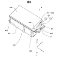
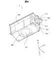
図5はカートリッジ4の外観斜視図、図6はカートリッジ4の分解斜視図、図7はカートリッジ4を底面側から見た外観斜視図、図8は回路基板410を未装着のカートリッジ4を底面側から見た外観斜視図である。図示するように、カートリッジ4は、筐体420と、蓋401と、回路基板410とを備える。蓋401は筐体420に固定され、筐体420が有する凹部421(図6参照)を覆う。この他、カートリッジ4は、第1液体保持部材406と、第2液体保持部材460と、蓋裏面シール部材436と、シール部材404とを備える。筐体420と蓋401は、ポリエチレンやポリプロピレン等の合成樹脂の成型品であり、射出成型等の適宜な成型手法にて形成される。
A-3. Configuration of cartridge 4:
5 is an external perspective view of the cartridge 4, FIG. 6 is an exploded perspective view of the cartridge 4, FIG. 7 is an external perspective view of the cartridge 4 viewed from the bottom side, and FIG. 8 is a bottom side of the cartridge 4 without the circuit board 410 mounted thereon. It is the external appearance perspective view seen from. As illustrated, the cartridge 4 includes a housing 420, a lid 401, and a circuit board 410. The lid 401 is fixed to the housing 420 and covers a recess 421 (see FIG. 6) included in the housing 420. In addition, the cartridge 4 includes a first liquid holding member 406, a second liquid holding member 460, a lid back surface seal member 436, and a seal member 404. The housing 420 and the lid 401 are molded products of synthetic resin such as polyethylene and polypropylene, and are formed by an appropriate molding technique such as injection molding.

筐体420は、底壁422と、第1端壁423と、第2端壁424と、第1側壁425と、第2側壁426とを有する。第1側壁425と第2側壁426とにおいて、外壁がリブ428にて補強されている。底壁422は、筐体420の底面をなし、その中央に液体供給孔407を備える。この底壁422は、蓋401(詳しくは後述の蓋部430)に対向する。第1端壁423は、底壁422から立ち上がり蓋401の蓋部430に交差する。第2端壁424は、底壁422から立ち上がって蓋401の蓋部430に交差すると共に、第1端壁423に対向する。第1側壁425は、第1端壁423の一方の端部(図6における−X方向端部)と第2端壁424の一方の端部(図6における−X方向端部)の間において底壁422から立ち上がって、蓋401の蓋部430に交差する。第2側壁426は、第1端壁423の他方の端部(図6における+X方向端部)と第2端壁424の他方の端部(図6における+X方向端部)の間において底壁422から立ち上がって、蓋401の蓋部430に交差すると共に第1側壁425と対向する。こうした壁面構成は、次のように表すこともできる。筐体420は、蓋401に対向する底壁422と、蓋401と底壁422に交差する第1端壁423と、蓋401と底壁422に交差し、第1端壁423に対向する第2端壁424と、蓋401と底壁422と第1端壁423と第2端壁424に交差する第1側壁425と、蓋401と底壁422と第1端壁423と第2端壁424に交差し、第1側壁425と対向する第2側壁426とを有する。   The housing 420 includes a bottom wall 422, a first end wall 423, a second end wall 424, a first side wall 425, and a second side wall 426. In the first side wall 425 and the second side wall 426, the outer wall is reinforced by ribs 428. The bottom wall 422 forms the bottom surface of the housing 420 and includes a liquid supply hole 407 in the center thereof. The bottom wall 422 faces the lid 401 (specifically, a lid portion 430 described later). The first end wall 423 rises from the bottom wall 422 and intersects the lid portion 430 of the lid 401. The second end wall 424 rises from the bottom wall 422 and intersects the lid portion 430 of the lid 401 and faces the first end wall 423. The first side wall 425 is between one end (the −X direction end in FIG. 6) of the first end wall 423 and one end (the −X direction end in FIG. 6) of the second end wall 424. It rises from the bottom wall 422 and intersects the lid portion 430 of the lid 401. The second side wall 426 is a bottom wall between the other end (the + X direction end in FIG. 6) of the first end wall 423 and the other end (the + X direction end in FIG. 6) of the second end wall 424. It rises from 422 and intersects the lid portion 430 of the lid 401 and faces the first side wall 425. Such a wall structure can also be expressed as follows. The housing 420 includes a bottom wall 422 that faces the lid 401, a first end wall 423 that intersects the lid 401 and the bottom wall 422, a first wall that intersects the lid 401 and the bottom wall 422, and faces the first end wall 423. Two end walls 424, a lid 401, a bottom wall 422, a first end wall 423, a first side wall 425 intersecting the second end wall 424, a lid 401, a bottom wall 422, a first end wall 423, and a second end wall. It has a second side wall 426 that intersects 424 and faces the first side wall 425.

回路基板410は、基板表面に複数の端子412を備え、筐体420の第1端壁423に位置する。この第1端壁423には、図8に示すように、基板載置部411が形成される。この基板載置部411は、第1端壁423に対して傾斜する。そして、回路基板410は、その背面を基板載置部411に固定され、第1端壁423に対して傾斜する。回路基板410において、端子412は、図7に示すように、いわゆる千鳥状に2列に配設され、カートリッジ4がキャリッジ8に既述したように装着されると、図4に示すように、キャリッジ8の側の電極集合体810の各電極に電気的に接続される。基板載置部411は、図8に示すように、奥側、即ち第1端壁423の外壁面側に開口413を備える。この開口413は、第1端壁423の外壁面に沿って第1端壁423の上端側から下端側までZ軸方向に延び(図6参照)、第1端壁423の上下端側で開口している。その一方、蓋401が筐体420に固定されると、開口413は、蓋401が備える後述の外方延在部431により、図8に示すように、第1端壁423の上端側で閉塞される。基板載置部411への回路基板410の固定には、基板載置部411から突出した凸部414が用いられる。図7に示すように、この凸部414が回路基板410から延びた状態において、凸部414が熱カシメされる。これにより、回路基板410は、基板載置部411に固定される。   The circuit board 410 includes a plurality of terminals 412 on the surface of the board, and is located on the first end wall 423 of the housing 420. As shown in FIG. 8, a substrate platform 411 is formed on the first end wall 423. The substrate platform 411 is inclined with respect to the first end wall 423. The circuit board 410 has its back surface fixed to the substrate platform 411 and tilted with respect to the first end wall 423. In the circuit board 410, the terminals 412 are arranged in two rows in a so-called zigzag pattern as shown in FIG. 7, and when the cartridge 4 is mounted on the carriage 8 as described above, as shown in FIG. It is electrically connected to each electrode of the electrode assembly 810 on the carriage 8 side. As shown in FIG. 8, the substrate platform 411 includes an opening 413 on the back side, that is, on the outer wall surface side of the first end wall 423. The opening 413 extends in the Z-axis direction from the upper end side to the lower end side of the first end wall 423 along the outer wall surface of the first end wall 423 (see FIG. 6), and opens at the upper and lower ends of the first end wall 423. doing. On the other hand, when the lid 401 is fixed to the housing 420, the opening 413 is closed on the upper end side of the first end wall 423 by an outward extending portion 431 provided in the lid 401, as will be described later. Is done. For fixing the circuit board 410 to the substrate platform 411, a convex portion 414 protruding from the substrate platform 411 is used. As shown in FIG. 7, in a state where the convex portion 414 extends from the circuit board 410, the convex portion 414 is heat caulked. As a result, the circuit board 410 is fixed to the substrate platform 411.

蓋401は、蓋部430と、外方延在部431とを備える。蓋部430は、平板状とされ、筐体420の凹部421を覆う。外方延在部431は、端子412を有する回路基板410が位置する第1端壁423の側において、蓋部430から外方に延在した部分であり、屈曲延在部432と、傾斜延在部433とを有する。屈曲延在部432は、蓋401から筐体420に向かう第1方向(図6における−Z方向)に沿って蓋部430からほぼ90度に屈曲させて突出するよう延びている。この屈曲延在部432に続く傾斜延在部433は、蓋401から筐体420に向かう第1方向(図6における−Z方向)からの蓋401の平面視において、回路基板410の端子412に重なる位置まで延びている。そして、この外方延在部431は、蓋401が筐体420に固定されると、図8に示すように、開口413と重なって、この開口413を第1端壁423の上端側で閉塞する。また、外方延在部431は、蓋401が筐体420に固定されると、図5に示すように、傾斜延在部433を基板載置部411の開口413に係合させる。この他、外方延在部431は、傾斜延在部433を、第2端壁424から第1端壁423に向かう第2方向(図4および図6における+Y方向)において、回路基板410の少なくとも下段側の端子412より外方に突出している。なお、傾斜延在部433を図示する状態からより長く延在させて、回路基板410の端子412の総てより外方に突出ようにしてもよい。   The lid 401 includes a lid portion 430 and an outwardly extending portion 431. The lid 430 has a flat plate shape and covers the recess 421 of the housing 420. The outward extending portion 431 is a portion extending outward from the lid portion 430 on the side of the first end wall 423 where the circuit board 410 having the terminals 412 is located. And a base portion 433. The bending extension portion 432 extends so as to protrude from the lid portion 430 by bending at approximately 90 degrees along a first direction (the −Z direction in FIG. 6) from the lid 401 toward the housing 420. The inclined extended portion 433 following the bent extended portion 432 is connected to the terminal 412 of the circuit board 410 in a plan view of the lid 401 from the first direction (the −Z direction in FIG. 6) from the lid 401 toward the housing 420. It extends to the overlapping position. When the lid 401 is fixed to the housing 420, the outwardly extending portion 431 overlaps with the opening 413 as shown in FIG. 8 and closes the opening 413 on the upper end side of the first end wall 423. To do. Further, when the lid 401 is fixed to the housing 420, the outward extending portion 431 engages the inclined extending portion 433 with the opening 413 of the substrate platform 411 as shown in FIG. In addition, the outwardly extending portion 431 has the inclined extending portion 433 formed on the circuit board 410 in the second direction (the + Y direction in FIGS. 4 and 6) from the second end wall 424 to the first end wall 423. At least the outer terminal 412 protrudes outward. It should be noted that the inclined extending portion 433 may be extended longer from the illustrated state so that all the terminals 412 of the circuit board 410 protrude outward.

蓋401は、既述した貫通孔402a,402b,402cとエアー溝403を備えるほか、大気連通孔434と、複数のシール部材受け座437とを備える。シール部材受け座437は、貫通孔402a,402b,402cの周壁やエアー溝403の周壁と同じ高さで蓋401の上面から突出し、シール部材404の接合受け座となる。   The lid 401 includes the above-described through holes 402a, 402b, and 402c and the air groove 403, and further includes an air communication hole 434 and a plurality of seal member receiving seats 437. The seal member receiving seat 437 protrudes from the upper surface of the lid 401 at the same height as the peripheral walls of the through holes 402 a, 402 b and 402 c and the peripheral wall of the air groove 403, and becomes a joint receiving seat for the seal member 404.

大気連通孔434は、蓋部430の一部がY軸方向に延びた蓋部外縁に形成され、この蓋部外縁において蓋401を貫通する。そして、この大気連通孔434は、蓋401の裏面側において貫通孔402cと図示しないエアー溝で繋げられる。当該エアー溝と大気連通孔434の蓋裏面側開口および貫通孔402cの蓋裏面側開口は、蓋裏面シール部材436にてシールされる。これにより、蓋401で塞がれた筐体420の凹部421を、貫通孔402aとエアー溝403と貫通孔402cを介して、大気連通孔434にて大気開放することができる。この大気開放を、第2液体保持部材460と関連付けて説明する。   The atmosphere communication hole 434 is formed at the outer edge of the lid portion in which a part of the lid portion 430 extends in the Y-axis direction, and penetrates the lid 401 at the outer edge of the lid portion. The atmospheric communication hole 434 is connected to the through hole 402 c by an air groove (not shown) on the back surface side of the lid 401. The air groove and the lid back surface side opening of the atmosphere communication hole 434 and the lid back surface side opening of the through hole 402c are sealed by a lid back surface seal member 436. As a result, the concave portion 421 of the housing 420 closed by the lid 401 can be opened to the atmosphere through the air communication hole 434 via the through hole 402a, the air groove 403, and the through hole 402c. This air release will be described in relation to the second liquid holding member 460.

第2液体保持部材460は、筐体420の凹部421に収納される。筐体420の底壁422は、液体供給孔407の周囲に段差状の半円状突起427を備え、この半円状突起427の段差部に、第1液体保持部材406が載置される(図4参照)。これにより、液体供給孔407は、第1液体保持部材406にて覆われる。また、底壁422は、各コーナー部位の周辺に、平面視で開放弧状の弧状突起429を備える。第2液体保持部材460は、各コーナーの弧状突起429および半円状突起427の上面で支えられるようにして、筐体420に収納される。このように第2液体保持部材460が収納されると、蓋裏面シール部材436やシール部材404が接合済みの蓋401が筐体420に溶着固定され、図4や図5に示すカートリッジ4が得られる。   The second liquid holding member 460 is accommodated in the recess 421 of the housing 420. The bottom wall 422 of the housing 420 includes a stepped semicircular protrusion 427 around the liquid supply hole 407, and the first liquid holding member 406 is placed on the stepped portion of the semicircular protrusion 427 ( (See FIG. 4). As a result, the liquid supply hole 407 is covered with the first liquid holding member 406. Further, the bottom wall 422 includes an arc-shaped protrusion 429 having an open arc shape in a plan view around each corner portion. The second liquid holding member 460 is accommodated in the housing 420 so as to be supported by the upper surfaces of the arc-shaped protrusion 429 and the semicircular protrusion 427 at each corner. When the second liquid holding member 460 is housed in this way, the lid 401 with the lid back surface sealing member 436 and the sealing member 404 bonded thereto is welded and fixed to the housing 420, and the cartridge 4 shown in FIGS. 4 and 5 is obtained. It is done.

第1液体保持部材406と第2液体保持部材460は、共に多孔質樹脂材を用いることができる。多孔質樹脂材とは、液体を保持できる機能を有すれば特に限定されるものではなく、例えばウレタンフォームのような発泡部材でもよいし、ポリプロピレンを繊維状にして束にした繊維部材であってもよい。第1液体保持部材406と第2液体保持部材460とは、液体を保持するための特性が異なる。第1液体保持部材406は、細孔の形成密度を示す細孔密度が第2液体保持部材460の第1保持部材461よりも大きくされている。   Both the first liquid holding member 406 and the second liquid holding member 460 can be made of a porous resin material. The porous resin material is not particularly limited as long as it has a function of holding a liquid. For example, a foamed member such as urethane foam may be used, or a fiber member in which polypropylene is made into a fiber and bundled. Also good. The first liquid holding member 406 and the second liquid holding member 460 have different characteristics for holding the liquid. The first liquid holding member 406 has a pore density indicating a pore formation density higher than that of the first holding member 461 of the second liquid holding member 460.

上記の細孔密度の大小関係より、第1液体保持部材406の毛管力は、第2液体保持部材460の毛管力よりも大きい。   Due to the magnitude relationship of the pore density, the capillary force of the first liquid holding member 406 is larger than the capillary force of the second liquid holding member 460.

第1液体保持部材406と第2液体保持部材460が毛管力について上記の大小関係を有することで、第2液体保持部材460に収容済みのインクは以下に述べる順で流通する。すなわち、毛管力の小さい部材から毛管力の大きい部材へとインクが流れる。図4に示すように、第1液体保持部材406に収容済みのインクが液体導入部703を介して吸引されて消費されると、第1液体保持部材406の上面に重なっている第2液体保持部材460に収容済みのインクが第1液体保持部材406に移動する。こうしたインク移動の駆動力は、主に第1液体保持部材406の毛管力である。そして、第2液体保持部材460の収納位置に対応する貫通孔402aとこれに繋がるエアー溝403および大気連通孔434からの大気連通により、上記したインク移動に支障は起きない。   Since the first liquid holding member 406 and the second liquid holding member 460 have the above-described magnitude relationship with respect to the capillary force, the ink stored in the second liquid holding member 460 flows in the order described below. That is, ink flows from a member having a small capillary force to a member having a large capillary force. As shown in FIG. 4, when the ink stored in the first liquid holding member 406 is sucked and consumed through the liquid introduction unit 703, the second liquid holding that overlaps the upper surface of the first liquid holding member 406 is performed. Ink stored in the member 460 moves to the first liquid holding member 406. The driving force for such ink movement is mainly the capillary force of the first liquid holding member 406. The above-described ink movement is not hindered by the atmospheric communication from the through hole 402a corresponding to the storage position of the second liquid holding member 460, the air groove 403 connected thereto, and the atmospheric communication hole 434.

上記のように、筐体420の凹部421に特性の異なる第1液体保持部材406と第2液体保持部材460が収容されると共に、液体導入部703に第1液体保持部材406よりも大きな毛管力を有するフィルター703fを用いることで、第2液体保持部材460に収容されているインクを効率良く消費できる。すなわち、第2液体保持部材460における未使用インクの残量を低減できる。   As described above, the first liquid holding member 406 and the second liquid holding member 460 having different characteristics are accommodated in the concave portion 421 of the housing 420, and the capillary force of the liquid introduction portion 703 is larger than that of the first liquid holding member 406. By using the filter 703f having the ink, the ink stored in the second liquid holding member 460 can be efficiently consumed. That is, the remaining amount of unused ink in the second liquid holding member 460 can be reduced.

なお、第1液体保持部材406と第2液体保持部材460の毛管力が、液体導入部703から離れるに従って小さくなる構成であれば、上記の各液体保持部材の細孔密度の大小関係は本実施形態に限定されるものではない。例えば、第1液体保持部材406と第2液体保持部材460の細孔密度が等しい場合でも、各液体保持部材に撥水処理や浸水処理を行うことで上記毛管力の大小関係を有するようにしてもよい。   If the capillary force of the first liquid holding member 406 and the second liquid holding member 460 is configured to decrease as the distance from the liquid introducing portion 703 increases, the relationship between the pore densities of the liquid holding members described above is the present embodiment. The form is not limited. For example, even when the pore densities of the first liquid holding member 406 and the second liquid holding member 460 are equal, each of the liquid holding members is subjected to water repellent treatment or water immersion treatment so that the capillary force has a magnitude relationship. Also good.

A−4.カートリッジ5の構成:
カートリッジ5は、イエロー、マゼンタ、シアンの3色のインクを収容する点でカートリッジ4と構成が相違する。よって、カートリッジ5についての構成の説明に当たっては、カートリッジ4と共通する構成については、符号番号の最上位桁の数値を値5に置き換えて示し、その説明を簡略化する。図9はカートリッジ5の外観斜視図、図10はカートリッジ5の分解斜視図、図11はカートリッジ5を底面側から見た外観斜視図、図12は回路基板510を未装着のカートリッジ5を底面側から見た外観斜視図である。図示するように、カートリッジ5は、筐体520と、蓋501と、回路基板510とを備える。蓋501は筐体520に固定され、筐体520が有する三つの凹部521(図10参照)を覆う。筐体520は、第1側壁525と第2側壁526との間に仕切壁571を、この仕切壁571と第2端壁524との間に仕切壁572を、仕切壁571と第1端壁523との間に仕切壁573を備える。これら仕切壁で、イエロー、マゼンタ、シアンの各色に対応した凹部521を形成する。そして、カートリッジ5は、それぞれの凹部521の底壁522の液体供給孔507の周囲の半円状突起527に第1液体保持部材506を載置し、第2液体保持部材560を第1液体保持部材506に重ねて収納する。
A-4. Configuration of cartridge 5:
The cartridge 5 is different from the cartridge 4 in that it contains three colors of yellow, magenta, and cyan. Therefore, in the description of the configuration of the cartridge 5, for the configuration common to the cartridge 4, the numerical value of the highest digit of the code number is replaced with the value 5 to simplify the description. 9 is an external perspective view of the cartridge 5, FIG. 10 is an exploded perspective view of the cartridge 5, FIG. 11 is an external perspective view of the cartridge 5 viewed from the bottom side, and FIG. 12 is a bottom side of the cartridge 5 without the circuit board 510 mounted thereon. It is the external appearance perspective view seen from. As illustrated, the cartridge 5 includes a housing 520, a lid 501, and a circuit board 510. The lid 501 is fixed to the housing 520 and covers three recesses 521 (see FIG. 10) of the housing 520. The housing 520 includes a partition wall 571 between the first side wall 525 and the second side wall 526, a partition wall 572 between the partition wall 571 and the second end wall 524, and the partition wall 571 and the first end wall. A partition wall 573 is provided between 523 and the terminal 523. With these partition walls, concave portions 521 corresponding to the respective colors of yellow, magenta, and cyan are formed. In the cartridge 5, the first liquid holding member 506 is placed on the semicircular protrusion 527 around the liquid supply hole 507 in the bottom wall 522 of each recess 521, and the second liquid holding member 560 is held in the first liquid holding state. The member 506 is stacked and stored.

筐体520が備える底壁522と、第1端壁523と、第2端壁524と、第1側壁525と、第2側壁526にあっても、カートリッジ4と同様の構成である。また、カートリッジ5は、回路基板510を、筐体520の第1端壁523に位置させ、この回路基板510を、カートリッジ4と同様に、基板載置部511に固定する。回路基板510における端子512の構成もほぼ同様であり、これら端子512の接触部は、カートリッジ5がキャリッジ8に既述したように装着されると、キャリッジ8の側の電極集合体810の各電極に電気的に接続される。基板載置部511の構成もカートリッジ4と同様であり、回路基板510は、基板載置部511から突出した凸部514の熱カシメにより、基板載置部511に固定される。   The structure of the bottom wall 522, the first end wall 523, the second end wall 524, the first side wall 525, and the second side wall 526 provided in the housing 520 is the same as that of the cartridge 4. In the cartridge 5, the circuit board 510 is positioned on the first end wall 523 of the housing 520, and the circuit board 510 is fixed to the substrate mounting portion 511 similarly to the cartridge 4. The configuration of the terminals 512 on the circuit board 510 is substantially the same, and the contact portions of these terminals 512 are the electrodes of the electrode assembly 810 on the carriage 8 side when the cartridge 5 is mounted on the carriage 8 as described above. Is electrically connected. The configuration of the substrate platform 511 is the same as that of the cartridge 4, and the circuit board 510 is fixed to the substrate platform 511 by thermal caulking of the convex portion 514 protruding from the substrate platform 511.

蓋501は、蓋部530と、外方延在部531とを備える。蓋部530は、平板状とされ、筐体520の三つの凹部521を覆う。外方延在部531は、端子512を有する回路基板510が位置する第1端壁523の側において、蓋部530から外方に延在する屈曲延在部532と、傾斜延在部533とを有する。これら延在部の構成は、カートリッジ4と同様である。屈曲延在部532は、蓋501から筐体520に向かう第1方向(図10における−Z方向)に沿って蓋部530からほぼ90度に屈曲させて突出するよう延びている。この屈曲延在部532に続く傾斜延在部533は、蓋501から筐体520に向かう第1方向(図10における−Z方向)からの蓋501の平面視において、回路基板510の端子512に重なるまで延びている。また、外方延在部531は、蓋501が筐体520に固定されると、図12に示すように、開口513と重なって、この開口513を第1端壁523の上端側で閉塞する。また、外方延在部531は、蓋501が筐体520に固定されると、図9に示すように、基板載置部511の開口513に係合する。この他、外方延在部531は、第2端壁524から第1端壁523に向かう第2方向(図4および図10における+Y方向)において、回路基板510の少なくとも下段側の端子512より外方に突出している。なお、傾斜延在部533を長く延在させて、回路基板510の端子512の総てより外方に突出ようにしてもよい。   The lid 501 includes a lid part 530 and an outwardly extending part 531. The lid portion 530 has a flat plate shape and covers the three concave portions 521 of the housing 520. The outward extending portion 531 includes a bent extending portion 532 that extends outward from the lid portion 530, an inclined extending portion 533, and the first end wall 523 on which the circuit board 510 having the terminals 512 is located. Have The configuration of these extending portions is the same as that of the cartridge 4. The bent extending portion 532 extends so as to protrude from the lid portion 530 by bending at approximately 90 degrees along a first direction (the −Z direction in FIG. 10) from the lid 501 toward the housing 520. The inclined extending portion 533 following the bent extending portion 532 is connected to the terminal 512 of the circuit board 510 in a plan view of the lid 501 from the first direction (the −Z direction in FIG. 10) from the lid 501 toward the housing 520. It extends until it overlaps. Further, when the lid 501 is fixed to the housing 520, the outward extending portion 531 overlaps the opening 513 as shown in FIG. 12, and closes the opening 513 on the upper end side of the first end wall 523. . Further, when the lid 501 is fixed to the housing 520, the outward extending portion 531 is engaged with the opening 513 of the substrate platform 511 as shown in FIG. In addition, the outward extending portion 531 is at least from the terminal 512 on the lower stage side of the circuit board 510 in the second direction (the + Y direction in FIGS. 4 and 10) from the second end wall 524 toward the first end wall 523. It protrudes outward. Note that the inclined extending portion 533 may be extended so as to protrude outward from all the terminals 512 of the circuit board 510.

蓋501は、イエロー、マゼンタ、シアンの各色ごとに、貫通孔502a,502b,502cと、貫通孔502aから貫通孔502cまでの間を延びるエアー溝503と、大気連通孔534と、各コーナーのシール部材受け座537とを備える。シール部材受け座537は、貫通孔502a,502b,502cの周壁やエアー溝503の周壁と同じ高さで蓋501の上面から突出し、シール部材504の接合受け座となる。   The lid 501 includes, for each of yellow, magenta, and cyan, through holes 502a, 502b, and 502c, an air groove 503 extending from the through hole 502a to the through hole 502c, an air communication hole 534, and seals at each corner. And a member receiving seat 537. The seal member receiving seat 537 protrudes from the upper surface of the lid 501 at the same height as the peripheral wall of the through holes 502 a, 502 b, and 502 c and the peripheral wall of the air groove 503, and becomes a joint receiving seat for the seal member 504.

三つの大気連通孔534は、蓋部530の外縁にX軸方向に並んで位置し、蓋501を貫通する。イエロー、マゼンタ、シアンの各色ごとの貫通孔502cは、各色ごとのエアー溝503の末端において蓋501を貫通し、X軸方向に並んだ大気連通孔534とY軸方向に重なって形成されている。そして、Y軸方向で重なった大気連通孔534と貫通孔502cとは、蓋501の裏面側において図示しないエアー溝で繋げられる。当該エアー溝と貫通孔502cの蓋裏面側開口および大気連通孔534の蓋裏面側開口は、蓋裏面シール部材536にてシールされる。これにより、蓋501で塞がれた筐体520の各色ごとの凹部521を、貫通孔502aとエアー溝503と貫通孔502cおよび大気連通孔534を介して、大気開放する。なお、貫通孔502a,502b,502cとエアー溝503は、シール部材504により、蓋上面側でシールされる。上記した大気開放により、蓋501で塞がれた筐体520の各色ごとの凹部521に収納された多孔質の第2液体保持部材560は、大気通気を受けながら、収容済みインクを第1液体保持部材506、延いては液体導入部703(図4参照)に供給する。   The three atmosphere communication holes 534 are located on the outer edge of the lid portion 530 in the X-axis direction and penetrate the lid 501. The through holes 502c for each color of yellow, magenta, and cyan are formed so as to penetrate the lid 501 at the end of the air groove 503 for each color and overlap with the air communication holes 534 arranged in the X-axis direction in the Y-axis direction. . The atmosphere communication hole 534 and the through hole 502c that overlap in the Y-axis direction are connected by an air groove (not shown) on the back surface side of the lid 501. The lid back side opening of the air groove and the through hole 502 c and the lid back side opening of the air communication hole 534 are sealed by a lid back surface sealing member 536. As a result, the recesses 521 for each color of the housing 520 closed with the lid 501 are opened to the atmosphere via the through holes 502 a, the air grooves 503, the through holes 502 c, and the atmosphere communication holes 534. The through holes 502a, 502b, and 502c and the air groove 503 are sealed on the upper surface side of the lid by the seal member 504. The porous second liquid holding member 560 accommodated in the concave portion 521 for each color of the casing 520 closed by the lid 501 by releasing the air described above receives the stored ink in the first liquid while receiving air ventilation. The holding member 506 is supplied to the liquid introduction portion 703 (see FIG. 4).

以上説明した構成を備える本実施形態のカートリッジ4は、筐体420の凹部421に収納した第2液体保持部材460に収容済みの液体としてのブラックインクを、キャリッジ8の液体導入部703を介してプリンター10に供給する。本実施形態のカートリッジ4は、回路基板410を、筐体420の第1端壁423に形成された基板載置部411に固定して備える。そして、キャリッジ装着状態において、基板表面の複数の端子412を、キャリッジ8の側の電極集合体810の各電極に電気的に接続する。その上で、本実施形態のカートリッジ4は、筐体420に固定されて凹部421を覆う蓋401を、凹部421を覆う蓋部430と第1端壁423の側において蓋部430から外方に延在する外方延在部431とを有するものとする。また、本実施形態のカートリッジ4は、蓋401の外方延在部431を、蓋401から筐体420に向かう第1方向(図6における−Z方向)に沿って蓋部430からほぼ90度に屈曲させて突出するよう延ばし、この屈曲延在部432に続く傾斜延在部433を、蓋401から筐体420に向かう第1方向(図6における−Z方向)からの蓋401の平面視において、回路基板410の端子412に重なるまで延ばして備える。このため、本実施形態のカートリッジ4は、屈曲延在部432とこれに続く傾斜延在部433とを有する外方延在部431を、蓋401から筐体420に向かう第1方向(図6における−Z方向)において、回路基板410の側に近づける。よって、本実施形態のカートリッジ4によれば、端子412を有する回路基板410を、蓋部430から延びた外方延在部431だけで保護できるので、外方延在部431単独での回路基板410、延いては端子412の保護機能の実効性を高めることができる。   In the cartridge 4 of the present embodiment having the above-described configuration, the black ink as the liquid already stored in the second liquid holding member 460 stored in the concave portion 421 of the housing 420 is supplied via the liquid introduction unit 703 of the carriage 8. Supplied to the printer 10. The cartridge 4 according to this embodiment includes a circuit board 410 fixed to a substrate mounting portion 411 formed on the first end wall 423 of the housing 420. In the carriage mounting state, the plurality of terminals 412 on the substrate surface are electrically connected to the respective electrodes of the electrode assembly 810 on the carriage 8 side. In addition, the cartridge 4 of the present embodiment is configured such that the lid 401 that is fixed to the housing 420 and covers the recess 421 is moved outward from the lid 430 on the side of the lid 430 and the first end wall 423 that covers the recess 421. It shall have the outward extension part 431 extended. Further, in the cartridge 4 of this embodiment, the outwardly extending portion 431 of the lid 401 is substantially 90 degrees from the lid portion 430 along the first direction (the −Z direction in FIG. 6) from the lid 401 toward the housing 420. A plan view of the lid 401 from the first direction (the −Z direction in FIG. 6) from the lid 401 toward the housing 420 is provided with an inclined extended portion 433 following the bent extended portion 432. The circuit board 410 is provided so as to extend until it overlaps the terminal 412 of the circuit board 410. For this reason, the cartridge 4 according to the present embodiment has an outward extending portion 431 having a bent extending portion 432 and an inclined extending portion 433 following the first extending direction from the lid 401 toward the housing 420 (FIG. 6). In the −Z direction), the circuit board is brought closer to the circuit board 410 side. Therefore, according to the cartridge 4 of the present embodiment, the circuit board 410 having the terminals 412 can be protected only by the outward extending part 431 extending from the lid part 430. Therefore, the circuit board alone by the outward extending part 431 is provided. 410, that is, the effectiveness of the protective function of the terminal 412 can be enhanced.

本実施形態のカートリッジ4は、筐体420の凹部421を覆う蓋401の蓋部430から第1方向に沿って外方延在部431を突出して延ばす。よって、本実施形態のカートリッジ4によれば、簡易な構造により、外方延在部431単独での回路基板410、延いては端子412の保護機能の実効性を高めることができる。   The cartridge 4 according to the present embodiment extends from the lid portion 430 of the lid 401 covering the concave portion 421 of the housing 420 by projecting the outward extending portion 431 along the first direction. Therefore, according to the cartridge 4 of the present embodiment, the effectiveness of the protection function of the circuit board 410 and the terminal 412 by the outward extending portion 431 alone can be enhanced with a simple structure.

本実施形態のカートリッジ4は、蓋401の外方延在部431を構成する屈曲延在部432を、蓋401から筐体420に向かう第1方向(図6における−Z方向)に沿って蓋部430からほぼ90度に屈曲させて突出するよう延ばしている。よって、本実施形態のカートリッジ4によれば、この屈曲延在部432の裏面を筐体420の第1端壁423の壁面に押し当てることで、蓋401の位置決め、詳しくは第1端壁423とこれに対向する第2端壁424を結ぶY軸方向の蓋401を位置決めが容易となる。   The cartridge 4 according to the present embodiment covers the bent extension portion 432 constituting the outward extension portion 431 of the lid 401 along the first direction (the −Z direction in FIG. 6) from the lid 401 toward the housing 420. It is extended from the portion 430 so as to be bent at approximately 90 degrees. Therefore, according to the cartridge 4 of the present embodiment, the back surface of the bent extended portion 432 is pressed against the wall surface of the first end wall 423 of the housing 420 to position the lid 401, specifically, the first end wall 423. And positioning of the lid 401 in the Y-axis direction connecting the second end wall 424 opposite to the second end wall 424 is facilitated.

本実施形態のカートリッジ4では、回路基板410を筐体420に固定するための基板載置部411が第1端壁423から突出形成される。また、基板載置部411の奥側、即ち第1端壁423の外壁面側に開口413に形成される。その上で、本実施形態のカートリッジ4は、この開口413を、筐体420に固定された蓋401の蓋部430から延びた外方延在部431の傾斜延在部433で閉塞する。基板載置部411への回路基板410の固定は、基板載置部411から突出した凸部414を回路基板410から延ばした状態において、この凸部414を熱カシメすることでなされる。凸部414の熱カシメに伴って熱が発生するが、本実施形態のカートリッジ4によれば、熱カシメに伴う熱を、基板載置部411の奥側の開口413に逃がすので、回路基板410が不用意に熱に晒されてしまうことを抑制できると共に、基板載置部411は元より筐体420に熱を伝播しないようにできる。また、本実施形態のカートリッジ4によれば、外方延在部431の傾斜延在部433による開口413の閉塞により、開口413への異物混入を防止できる。   In the cartridge 4 of the present embodiment, a substrate mounting portion 411 for fixing the circuit substrate 410 to the housing 420 is formed to protrude from the first end wall 423. Further, the opening 413 is formed on the back side of the substrate platform 411, that is, on the outer wall surface side of the first end wall 423. In addition, the cartridge 4 according to the present embodiment closes the opening 413 with the inclined extending portion 433 of the outward extending portion 431 extending from the lid portion 430 of the lid 401 fixed to the housing 420. The circuit board 410 is fixed to the substrate platform 411 by heat-caulking the projection 414 in a state where the projection 414 protruding from the substrate platform 411 extends from the circuit board 410. Although heat is generated along with the heat caulking of the convex portion 414, according to the cartridge 4 of this embodiment, the heat due to the heat caulking is released to the opening 413 on the back side of the substrate mounting portion 411. Can be prevented from being inadvertently exposed to heat, and the substrate platform 411 can prevent heat from being propagated to the housing 420 from the beginning. Further, according to the cartridge 4 of the present embodiment, foreign matter mixing into the opening 413 can be prevented by closing the opening 413 by the inclined extending portion 433 of the outward extending portion 431.

本実施形態のカートリッジ4は、外方延在部431を構成する傾斜延在部433を、基板載置部411の開口413に係合させる。よって、本実施形態のカートリッジ4によれば、外方延在部431により基板載置部411を補強できるので、この基板載置部411への回路基板410の固定に支障を来さない。   In the cartridge 4 of this embodiment, the inclined extending portion 433 constituting the outward extending portion 431 is engaged with the opening 413 of the substrate mounting portion 411. Therefore, according to the cartridge 4 of the present embodiment, the substrate mounting portion 411 can be reinforced by the outward extending portion 431, so that the fixing of the circuit board 410 to the substrate mounting portion 411 is not hindered.

本実施形態のカートリッジ4は、筐体420を、凹部421の底面をなして蓋401の蓋部430に対向する底壁422と、この底壁422から立ち上がって蓋部430に交差する第1端壁423と、底壁422から立ち上がって蓋部430に交差すると共に第1端壁423に対向する第2端壁424と、第1端壁423の一方の端部と第2端壁424の一方の端部の間において底壁422から立ち上がって蓋部430に交差する第1側壁425と、第1端壁423の他方の端部と第2端壁424の他方の端部の間において底壁422から立ち上がって蓋部430に交差すると共に第1側壁425と対向する第2側壁426とで構成している。また、カートリッジ4は、蓋部430から延びる外方延在部431を、第2端壁424から第1端壁423に向かう第2方向(図4および図6における+Y方向)において、回路基板410の少なくとも下段側の端子412の接触部より外方に突出させている。よって、本実施形態のカートリッジ4によれば、外方延在部431単独での回路基板410,延いては端子412の接触部の保護機能の実効性を上記の第2方向においても高めることができる。上記した各効果は、カートリッジ5においても奏することができる。   The cartridge 4 according to the present embodiment includes a housing 420 having a bottom wall 422 that forms the bottom surface of the recess 421 and faces the lid portion 430 of the lid 401, and a first end that rises from the bottom wall 422 and intersects the lid portion 430. A wall 423, a second end wall 424 that rises from the bottom wall 422 and intersects the lid 430 and faces the first end wall 423; one end of the first end wall 423 and one of the second end walls 424 The first side wall 425 that rises from the bottom wall 422 between the ends of the first end wall 422 and intersects the lid 430, and the bottom wall between the other end of the first end wall 423 and the other end of the second end wall 424 A second side wall 426 that rises from 422 and intersects the lid 430 and faces the first side wall 425 is formed. Further, the cartridge 4 has an outward extending portion 431 extending from the lid portion 430 in the second direction (the + Y direction in FIGS. 4 and 6) from the second end wall 424 to the first end wall 423. Are protruded outward from at least the contact portion of the lower terminal 412. Therefore, according to the cartridge 4 of the present embodiment, the effectiveness of the protection function of the circuit board 410 by the outward extending portion 431 alone and the contact portion of the terminal 412 can be enhanced also in the second direction. it can. Each effect described above can also be achieved in the cartridge 5.

既存のカートリッジは、外方延在部431や外方延在部531を備えない蓋を筐体420や筐体520に固定して、基板載置部411或いは基板載置部511にて回路基板410、回路基板510を固定する。本実施形態のカートリッジ4およびカートリッジ5は、上記した既存のカートリッジにおける蓋を外方延在部431或いは外方延在部531を備えたものに他ならないことから、既存カートリッジに代替えできる。   In the existing cartridge, a lid that does not include the outward extending portion 431 or the outward extending portion 531 is fixed to the housing 420 or the housing 520, and the circuit board is mounted on the substrate mounting portion 411 or the substrate mounting portion 511. 410, the circuit board 510 is fixed. The cartridge 4 and the cartridge 5 of the present embodiment can be replaced with the existing cartridge because the lid of the above-described existing cartridge is nothing but the outward extending portion 431 or the outward extending portion 531.

B.第2実施形態:
図13は他の実施形態のカートリッジ4Aの概略を示す説明図である。このカートリッジ4Aでは、蓋401における外方延在部431は、傾斜延在部433に繋がってY軸方向に延びる延在係合腕部435を有する。この延在係合腕部435は、キャリッジ8がカートリッジの保持と装着済みカートリッジの抜止を図るカートリッジ係合腕801に係合するよう延びている。よって、この実施形態のカートリッジ4Aによれば、外方延在部431を構成する延在係合腕部435によりプリンター10への係合機能も発揮できる。
B. Second embodiment:
FIG. 13 is an explanatory view showing an outline of a cartridge 4A of another embodiment. In this cartridge 4 </ b> A, the outward extending portion 431 of the lid 401 has an extending engagement arm portion 435 that is connected to the inclined extending portion 433 and extends in the Y-axis direction. The extended engagement arm portion 435 extends so that the carriage 8 engages with a cartridge engagement arm 801 that holds the cartridge and prevents the mounted cartridge from being removed. Therefore, according to the cartridge 4A of this embodiment, the function of engaging with the printer 10 can be exhibited by the extended engagement arm portion 435 constituting the outward extending portion 431.

C.第3実施形態:
図14はまた別の実施形態のカートリッジ4Bの概略を示す説明図である。このカートリッジ4Bでは、カートリッジ4Aと同様、蓋401における外方延在部431は、傾斜延在部433に繋がってY軸方向に延びる延在係合腕部435を有する。そして、カートリッジ4Bは、筐体420の第1端壁423にカートリッジ係合腕490を備える。このカートリッジ係合腕490は、可撓性を備え、プリンター10のキャリッジ8が備える図示しないカートリッジ係合部と係合可能とされている。外方延在部431は、蓋401から筐体420に向かう第1方向に沿って蓋部430から突出して延在している。また、外方延在部431は、この第1方向からの蓋401の平面視において、カートリッジ係合腕490と重なる位置まで延在している。より詳しくは、外方延在部431を構成する延在係合腕部435はカートリッジ係合腕490と重なる位置まで延在している。この場合、延在係合腕部435は傾斜延在部433に連続するよう傾斜したり、傾斜延在部433から湾曲しつつ上記の第一方向に沿って延びるようにしてもよい。このため、この実施形態のカートリッジ4Bは、屈曲延在部432とこれに続く傾斜延在部433および延在係合腕部435を有する外方延在部431を、蓋401から筐体420に向かう第1方向(図14における−Z方向)において、カートリッジ係合腕490の側に近接させることができる。よって、この実施形態のカートリッジ4Bによれば、蓋部430から延びた外方延在部431によるカートリッジ係合腕490の保護機能の実効性を高めることができる。
C. Third embodiment:
FIG. 14 is an explanatory diagram showing an outline of a cartridge 4B according to another embodiment. In the cartridge 4B, as in the cartridge 4A, the outwardly extending portion 431 of the lid 401 has an extending engaging arm portion 435 that is connected to the inclined extending portion 433 and extends in the Y-axis direction. The cartridge 4 </ b> B includes a cartridge engagement arm 490 on the first end wall 423 of the housing 420. The cartridge engaging arm 490 is flexible and can be engaged with a cartridge engaging portion (not shown) included in the carriage 8 of the printer 10. The outward extending portion 431 protrudes and extends from the lid portion 430 along the first direction from the lid 401 toward the housing 420. Further, the outward extending portion 431 extends to a position overlapping the cartridge engaging arm 490 in the plan view of the lid 401 from the first direction. More specifically, the extended engaging arm portion 435 constituting the outward extending portion 431 extends to a position where it overlaps with the cartridge engaging arm 490. In this case, the extended engagement arm portion 435 may be inclined so as to be continuous with the inclined extended portion 433, or may be extended along the first direction while being curved from the inclined extended portion 433. For this reason, the cartridge 4B of this embodiment has an outwardly extending portion 431 having a bent extending portion 432, an inclined extending portion 433 and an extending engaging arm portion 435, which is connected from the lid 401 to the housing 420. In the first direction toward the head (the −Z direction in FIG. 14), the cartridge can be brought close to the arm 490 side. Therefore, according to the cartridge 4B of this embodiment, the effectiveness of the protective function of the cartridge engaging arm 490 by the outward extending portion 431 extending from the lid portion 430 can be enhanced.

この実施形態のカートリッジ4Bは、筐体420の凹部421を覆う蓋401の蓋部430から第1方向に沿って外方延在部431を突出して延ばす。よって、この実施形態のカートリッジ4Bによれば、簡易な構造により、外方延在部431によるカートリッジ係合腕490の保護機能の実効性を高めることができる。   In the cartridge 4B of this embodiment, an outwardly extending portion 431 extends from the lid portion 430 of the lid 401 that covers the concave portion 421 of the housing 420 along the first direction. Therefore, according to the cartridge 4B of this embodiment, the effectiveness of the protective function of the cartridge engaging arm 490 by the outward extending portion 431 can be enhanced with a simple structure.

この実施形態のカートリッジ4Bは、筐体420を、既述したカートリッジ4と同様、凹部421の底面をなして蓋401の蓋部430に対向する底壁422、第1端壁423、第2端壁424、第1側壁425および第2側壁426とで構成している。また、カートリッジ4Bは、蓋部430から延びる外方延在部431を、第2端壁424から第1端壁423に向かう第2方向(図14における+Y方向)において、カートリッジ係合腕490より外方に突出させている。よって、この実施形態のカートリッジ4Bによれば、外方延在部431によるカートリッジ係合腕490の保護機能の実効性を上記の第2方向においても高めることができる。   In the cartridge 4B of this embodiment, the housing 420 has a bottom wall 422, a first end wall 423, and a second end that form the bottom surface of the recess 421 and face the lid portion 430 of the lid 401, like the cartridge 4 described above. A wall 424, a first side wall 425, and a second side wall 426 are configured. In addition, the cartridge 4B has an outwardly extending portion 431 extending from the lid portion 430 and a cartridge engaging arm 490 in the second direction (the + Y direction in FIG. 14) from the second end wall 424 to the first end wall 423. It protrudes outward. Therefore, according to the cartridge 4B of this embodiment, the effectiveness of the protective function of the cartridge engaging arm 490 by the outward extending portion 431 can be enhanced also in the second direction.

D.変形例:
本発明は、インクジェットプリンターおよびそのインクカートリッジに限らず、インク以外の他の液体を噴射する任意の液体噴射装置およびその液体を収容するためのカートリッジ(液体収容容器)にも適用することができる。例えば、以下のような各種の液体噴射装置およびその液体収容容器に適用可能である。
(1)ファクシミリ装置等の画像記録装置
(2)液晶ディスプレイ等の画像表示装置用のカラーフィルタの製造に用いられる色材噴射装置
(3)有機EL(Electro Luminescence)ディスプレイや、面発光ディスプレイ (Field Emission Display、FED)等の電極形成に用いられる電極材噴射装置
(4)バイオチップ製造に用いられる生体有機物を含む液体を噴射する液体噴射装置
(5)精密ピペットとしての試料噴射装置
(6)潤滑油の噴射装置
(7)樹脂液の噴射装置
(8)時計やカメラ等の精密機械にピンポイントで潤滑油を噴射する液体噴射装置
(9)光通信素子等に用いられる微小半球レンズ(光学レンズ)などを形成するために紫外線硬化樹脂液等の透明樹脂液を基板上に噴射する液体噴射装置
(10)基板などをエッチングするために酸性又はアルカリ性のエッチング液を噴射する液体噴射装置
(11)他の任意の微小量の液滴を吐出させる液体噴射吐出ヘッドを備える液体噴射装置
D. Variations:
The present invention can be applied not only to an ink jet printer and its ink cartridge, but also to any liquid ejecting apparatus that ejects liquid other than ink and a cartridge (liquid container) for containing the liquid. For example, the present invention can be applied to the following various liquid ejecting apparatuses and the liquid storage containers.
(1) Image recording device such as a facsimile machine (2) Color material injection device used for manufacturing a color filter for an image display device such as a liquid crystal display (3) Organic EL (Electro Luminescence) display, surface emitting display (Field Electrode material injection device used for electrode formation such as Emission Display (FED), etc. (4) Liquid injection device for injecting liquid containing biological organic material used for biochip manufacturing (5) Sample injection device as a precision pipette (6) Lubrication Oil injection device (7) Resin liquid injection device (8) Liquid injection device for injecting lubricating oil pinpoint to precision machines such as watches and cameras (9) Micro hemispherical lenses (optical lenses) used in optical communication elements, etc. ), Etc., to inject a transparent resin liquid such as an ultraviolet curable resin liquid onto the substrate (10) Acid or to etch the substrate A liquid ejecting apparatus that ejects alkaline of the etching solution (11) any other liquid ejecting apparatus including a liquid ejecting ejection head for discharging minute liquid droplets

なお、「液滴」とは、液体噴射装置から吐出される液体の状態をいい、粒状、涙状、糸状に尾を引くものも含むものとする。また、ここでいう「液体」とは、液体噴射装置が噴射させることができるような材料であれば良い。例えば、「液体」は、物質が液相であるときの状態の材料であれば良く、粘性の高い又は低い液状態の材料、および、ゾルゲル法での流体材料、その他の無機溶剤、有機溶剤、溶液、液状樹脂、液状金属(金属融液)のような液状態の材料も「液体」に含まれる。また、物質の一状態としての液体のみならず、顔料や金属粒子などの固形物からなる機能材料の粒子が溶媒に溶解、分散または混合されたものなども「液体」に含まれる。また、液体の代表的な例としては上記実施形態で説明したようなインクや液晶等が挙げられる。ここで、インクとは一般的な水性インクおよび油性インク並びにジェルインク、ホットメルトインク等の各種の液体状組成物を包含するものとする。   The “droplet” refers to the state of the liquid ejected from the liquid ejecting apparatus, and includes those that have tails in the form of particles, tears, and threads. The “liquid” here may be any material that can be ejected by the liquid ejecting apparatus. For example, the “liquid” may be a material in a state when the substance is in a liquid phase, a material having a high or low viscosity, a fluid material in a sol-gel method, other inorganic solvents, organic solvents, Liquid materials such as solutions, liquid resins, and liquid metals (metal melts) are also included in the “liquid”. Further, “liquid” includes not only a liquid as one state of a substance but also a liquid obtained by dissolving, dispersing or mixing particles of a functional material made of a solid such as a pigment or metal particles in a solvent. Further, representative examples of the liquid include ink and liquid crystal as described in the above embodiment. Here, the ink includes various liquid compositions such as general water-based ink and oil-based ink, gel ink, and hot-melt ink.

本発明は、上述の実施形態や実施例、変形例に限られるものではなく、その趣旨を逸脱しない範囲において種々の構成で実現することができる。例えば、発明の概要の欄に記載した各形態中の技術的特徴に対応する実施形態、実施例、変形例中の技術的特徴は、上述の課題の一部又は全部を解決するために、あるいは、上述の効果の一部又は全部を達成するために、適宜、差し替えや、組み合わせを行うことが可能である。また、その技術的特徴が本明細書中に必須なものとして説明されていなければ、適宜、削除することが可能である。   The present invention is not limited to the above-described embodiments, examples, and modifications, and can be realized with various configurations without departing from the spirit thereof. For example, the technical features in the embodiments, examples, and modifications corresponding to the technical features in each embodiment described in the summary section of the invention are to solve some or all of the above-described problems, or In order to achieve part or all of the above effects, replacement or combination can be performed as appropriate. Further, if the technical feature is not described as essential in the present specification, it can be deleted as appropriate.

1…液体噴射システム
4…カートリッジ(第1のカートリッジ)
4A、4B…カートリッジ
5…カートリッジ(第2のカートリッジ)
6…記録部
7…カートリッジ装着部
8…キャリッジ
9…排出部
10…プリンター
12…装置本体
14…ハウジング
16…用紙供給部カバー
16a…載置面
18…記録部保護カバー
20…排出部カバー
22…操作部
24…用紙供給部
26…用紙開口部
28…用紙ガイド
50…搬送ローラー軸
60…制御部
62…キャリッジガイド軸
401…蓋
402a,402b,402c…貫通孔
403…エアー溝
404…シール部材
405…係合部
406…第1液体保持部材
407…液体供給孔
408…液体供給孔周縁部
410…回路基板
411…基板載置部
412…端子(接触部)
413…開口
414…凸部
420…筐体
421…凹部
422…底壁
423…第1端壁
424…第2端壁
425…第1側壁
426…第2側壁
427…半円状突起
428…リブ
429…弧状突起
430…蓋部
431…外方延在部
432…屈曲延在部
433…傾斜延在部
434…大気連通孔
435…延在係合腕部
436…蓋裏面シール部材
437…シール部材受け座
460…第2液体保持部材
490…カートリッジ係合腕
501…蓋
502a,502b,502c…貫通孔
503…エアー溝
504…シール部材
505…係合部
506…第1液体保持部材
507…液体供給孔
510…回路基板
511…基板載置部
512…端子(接触部)
513…開口
514…凸部
520…筐体
521…凹部
522…底壁
523…第1端壁
524…第2端壁
525…第1側壁
526…第2側壁
527…半円状突起
530…蓋部
531…外方延在部
532…屈曲延在部
533…傾斜延在部
534…大気連通孔
536…蓋裏面シール部材
537…シール部材受け座
560…第2液体保持部材
571…仕切壁
572…仕切壁
573…仕切壁
703…液体導入部
703f…フィルター
704…吸引孔
705…弾性部材
801…カートリッジ係合腕
810…電極集合体
DESCRIPTION OF SYMBOLS 1 ... Liquid injection system 4 ... Cartridge (1st cartridge)
4A, 4B ... cartridge 5 ... cartridge (second cartridge)
DESCRIPTION OF SYMBOLS 6 ... Recording part 7 ... Cartridge mounting part 8 ... Carriage 9 ... Ejection part 10 ... Printer 12 ... Apparatus main body 14 ... Housing 16 ... Paper supply part cover 16a ... Loading surface 18 ... Recording part protective cover 20 ... Ejection part cover 22 ... Operation unit 24 ... paper supply unit 26 ... paper opening 28 ... paper guide 50 ... conveying roller shaft 60 ... control unit 62 ... carriage guide shaft 401 ... lid 402a, 402b, 402c ... through hole 403 ... air groove 404 ... sealing member 405 ... engaging part 406 ... first liquid holding member 407 ... liquid supply hole 408 ... liquid supply hole peripheral part 410 ... circuit board 411 ... substrate mounting part 412 ... terminal (contact part)
413 ... opening 414 ... convex part 420 ... housing 421 ... concave part 422 ... bottom wall 423 ... first end wall 424 ... second end wall 425 ... first side wall 426 ... second side wall 427 ... semicircular protrusion 428 ... rib 429 ... Arc-shaped protrusion 430 ... Lid 431 ... Outwardly extending part 432 ... Bending extension part 433 ... Inclined extension part 434 ... Atmospheric communication hole 435 ... Extending engagement arm part 436 ... Lid back surface seal member 437 ... Seal member receiver Seat 460 ... second liquid holding member 490 ... cartridge engaging arm 501 ... lid 502a, 502b, 502c ... through hole 503 ... air groove 504 ... sealing member 505 ... engaging portion 506 ... first liquid holding member 507 ... liquid supply hole 510 ... Circuit board 511 ... Board placement part 512 ... Terminal (contact part)
513: Opening 514 ... Projection 520 ... Housing 521 ... Concave 522 ... Bottom wall 523 ... First end wall 524 ... Second end wall 525 ... First side wall 526 ... Second side wall 527 ... Semicircular projection 530 ... Lid 531 ... Outwardly extending portion 532 ... Bending extended portion 533 ... Inclined extending portion 534 ... Atmospheric communication hole 536 ... Cover back surface seal member 537 ... Seal member receiving seat 560 ... Second liquid holding member 571 ... Partition wall 572 ... Partition Wall 573 ... Partition wall 703 ... Liquid introduction part 703f ... Filter 704 ... Suction hole 705 ... Elastic member 801 ... Cartridge engagement arm 810 ... Electrode assembly

Claims (7)

液体を液体噴射装置に供給可能な液体供給ユニットであって、
凹部を有する筐体と、
前記凹部を覆い前記筐体に固定される蓋と、
前記筐体の外側壁に位置し、前記液体噴射装置の電極と電気的接触可能な端子と、を備え、
前記蓋は、前記凹部を覆う蓋部と、前記端子が位置する前記外側壁の側において、前記蓋部から外方に延在する外方延在部とを有し、
該外方延在部は、前記蓋から前記筐体に向かう第1方向に沿って前記蓋部から突出して延び、前記第1方向からの前記蓋の平面視において、前記端子と重なるまで延在する、液体供給ユニット。
A liquid supply unit capable of supplying liquid to a liquid ejecting apparatus,
A housing having a recess;
A lid that covers the recess and is fixed to the housing;
A terminal located on an outer wall of the housing, and electrically contactable with an electrode of the liquid ejecting apparatus;
The lid has a lid portion that covers the recess, and an outwardly extending portion that extends outward from the lid portion on the outer wall side where the terminal is located,
The outward extending portion extends from the lid along the first direction from the lid toward the housing, and extends until it overlaps the terminal in a plan view of the lid from the first direction. A liquid supply unit.
請求項1に記載の液体供給ユニットにおいて、
前記端子は回路基板に形成され、
前記筐体は前記回路基板が固定される載置部を前記外側壁に有し、
前記載置部には前記回路基板と重なる位置に開口が形成され、
前記第1方向からの前記蓋の平面視において、前記蓋の前記外方延在部は前記開口と重なる、液体供給ユニット。
The liquid supply unit according to claim 1, wherein
The terminals are formed on a circuit board;
The housing has a mounting portion on the outer wall to which the circuit board is fixed,
An opening is formed in the mounting portion at a position overlapping the circuit board,
The liquid supply unit, wherein the outwardly extending portion of the lid overlaps the opening in a plan view of the lid from the first direction.
前記蓋の前記外方延在部は前記載置部に係合する突出端を備える請求項2に記載の液体供給ユニット。   The liquid supply unit according to claim 2, wherein the outwardly extending portion of the lid includes a protruding end that engages with the mounting portion. 請求項1から請求項3のいずれか一項に記載の液体供給ユニットにおいて、
前記筐体は、前記凹部の底面をなして前記蓋の前記蓋部に対向する底壁と、該底壁から立ち上がり前記蓋の前記蓋部に交差する第1側壁と、前記底壁から立ち上がって前記蓋の前記蓋部に交差すると共に前記第1側壁に対向する第2側壁と、前記第1側壁の一方の端部と前記第2側壁の一方の端部の間において前記底壁から立ち上がって前記蓋の前記蓋部に交差する第1端壁と、前記第1側壁の他方の端部と前記第2側壁の他方の端部の間において前記底壁から立ち上がって前記蓋の前記蓋部に交差すると共に前記第1端壁と対向する第2端壁と、を有し、
前記端子は、前記外側壁としての前記第1端壁に位置し、
前記第2端壁から前記第1端壁に向かう第2方向において、前記蓋の前記外方延在部は前記端子より外方に突出している、液体供給ユニット。
The liquid supply unit according to any one of claims 1 to 3,
The housing includes a bottom wall that forms the bottom surface of the recess and faces the lid portion of the lid, a first side wall that rises from the bottom wall and intersects the lid portion of the lid, and rises from the bottom wall A second side wall that intersects the lid portion of the lid and faces the first side wall, and rises from the bottom wall between one end of the first side wall and one end of the second side wall. A first end wall that intersects the lid portion of the lid, and rises from the bottom wall between the other end portion of the first side wall and the other end portion of the second side wall to the lid portion of the lid. A second end wall that intersects and opposes the first end wall;
The terminal is located on the first end wall as the outer wall;
The liquid supply unit, wherein the outwardly extending portion of the lid projects outward from the terminal in a second direction from the second end wall to the first end wall.
請求項1から請求項4のいずれか一項に記載の液体供給ユニットにおいて、
前記蓋の前記外方延在部は前記液体噴射装置と係合可能な係合部を有する、液体供給ユニット。
In the liquid supply unit according to any one of claims 1 to 4,
The liquid supply unit, wherein the outwardly extending portion of the lid has an engaging portion engageable with the liquid ejecting apparatus.
液体を液体噴射装置に供給可能な液体供給ユニットであって、
凹部を有する筐体と、
該筐体に固定されて前記凹部を覆う蓋と、
前記筐体の外側壁に位置し、前記液体噴射装置と係合可能な係合部と、を備え、
前記蓋は、前記凹部を覆う蓋部と、前記係合部が位置する前記外側壁の側において、前記蓋部から外方に延在する外方延在部とを有し、
該外方延在部は、前記蓋から前記筐体に向かう第1方向に沿って前記蓋部から突出して延び、前記第1方向からの前記蓋の平面視において、前記係合部と重なるまで延在する、液体供給ユニット。
A liquid supply unit capable of supplying liquid to a liquid ejecting apparatus,
A housing having a recess;
A lid fixed to the housing and covering the recess;
An engagement portion located on an outer wall of the housing and engageable with the liquid ejecting apparatus,
The lid includes a lid portion that covers the recess, and an outwardly extending portion that extends outward from the lid portion on the outer wall side where the engaging portion is located,
The outwardly extending portion protrudes from the lid portion along the first direction from the lid toward the housing, and overlaps with the engagement portion in a plan view of the lid from the first direction. An extended liquid supply unit.
請求項6に記載の液体供給ユニットにおいて、
前記筐体は、前記凹部の底面をなして前記蓋の前記蓋部に対向する底壁と、該底壁から立ち上がり前記蓋の前記蓋部に交差する第1側壁と、前記底壁から立ち上がって前記蓋の前記蓋部に交差すると共に前記第1側壁に対向する第2側壁と、前記第1側壁の一方の端部と前記第2側壁の一方の端部の間において前記底壁から立ち上がって前記蓋の前記蓋部に交差する第1端壁と、前記第1側壁の他方の端部と前記第2側壁の他方の端部の間において前記底壁から立ち上がって前記蓋の前記蓋部に交差すると共に前記第1端壁と対向する第2端壁と、を有し、
前記係合部は、前記外側壁としての前記第1端壁に位置し、
前記第2端壁から前記第1端壁に向かう第2方向において、前記蓋の前記外方延在部は前記係合部より外方に突出している、液体供給ユニット。
The liquid supply unit according to claim 6, wherein
The housing includes a bottom wall that forms the bottom surface of the recess and faces the lid portion of the lid, a first side wall that rises from the bottom wall and intersects the lid portion of the lid, and rises from the bottom wall A second side wall that intersects the lid portion of the lid and faces the first side wall, and rises from the bottom wall between one end of the first side wall and one end of the second side wall. A first end wall that intersects the lid portion of the lid, and rises from the bottom wall between the other end portion of the first side wall and the other end portion of the second side wall to the lid portion of the lid. A second end wall that intersects and opposes the first end wall;
The engaging portion is located on the first end wall as the outer wall,
The liquid supply unit, wherein the outwardly extending portion of the lid projects outward from the engaging portion in a second direction from the second end wall toward the first end wall.
JP2014015767A 2013-12-18 2014-01-30 Liquid supply unit Active JP6233062B2 (en)

Priority Applications (62)

Application Number Priority Date Filing Date Title
JP2014015767A JP6233062B2 (en) 2014-01-30 2014-01-30 Liquid supply unit
CA2932434A CA2932434C (en) 2013-12-18 2014-12-09 Liquid supply unit
RU2016123602A RU2660070C1 (en) 2013-12-18 2014-12-09 Liquid supply unit
AU2014368304A AU2014368304B2 (en) 2013-12-18 2014-12-09 Liquid supply unit
PCT/JP2014/006136 WO2015093008A1 (en) 2013-12-18 2014-12-09 Liquid supply unit
PCT/JP2014/006167 WO2015093012A1 (en) 2013-12-18 2014-12-10 Liquid supply unit
CA2932696A CA2932696C (en) 2013-12-18 2014-12-12 Liquid supply unit
RU2016123600A RU2645206C2 (en) 2013-12-18 2014-12-12 Fluid feed unit
PCT/JP2014/006221 WO2015093027A1 (en) 2013-12-18 2014-12-12 Liquid supply unit-mounting mechanism and liquid supply unit
AU2014368232A AU2014368232B2 (en) 2013-12-18 2014-12-12 Liquid supply unit
CN201410770713.6A CN104723683B (en) 2013-12-18 2014-12-12 Fluid supply unit
CN201420790410.6U CN204506139U (en) 2013-12-18 2014-12-12 Fluid supply unit
CN201410773179.4A CN104723684B (en) 2013-12-18 2014-12-12 Fluid supply unit
BR112016014143-1A BR112016014143A2 (en) 2013-12-18 2014-12-12 LIQUID SUPPLY UNIT
CN201710561409.4A CN107297957B (en) 2013-12-18 2014-12-12 Fluid supply unit
CN201710971238.2A CN107672316A (en) 2013-12-18 2014-12-12 Fluid supply unit
PCT/JP2014/006222 WO2015093028A1 (en) 2013-12-18 2014-12-12 Liquid supply unit
PCT/JP2014/006187 WO2015093016A1 (en) 2013-12-18 2014-12-12 Liquid supply unit
CN201420788209.4U CN204472115U (en) 2013-12-18 2014-12-12 Fluid supply unit
PCT/JP2014/006218 WO2015093024A1 (en) 2013-12-18 2014-12-12 Liquid supply unit
CN201410776917.0A CN104723685B (en) 2013-12-18 2014-12-15 Fluid supply unit
CN201711306297.4A CN107891670B (en) 2013-12-18 2014-12-15 Fluid supply unit
CN201410778150.5A CN104723686B (en) 2013-12-18 2014-12-15 Fluid supply unit
CN201420795684.4U CN204605190U (en) 2013-12-18 2014-12-15 Fluid supply unit
CN201420797072.9U CN204566928U (en) 2013-12-18 2014-12-15 Fluid supply unit
ES14198198T ES2746323T3 (en) 2013-12-18 2014-12-16 Liquid supply unit
ES14198200.9T ES2691520T3 (en) 2013-12-18 2014-12-16 Liquid supply unit
ES14198197T ES2704093T3 (en) 2013-12-18 2014-12-16 Liquid supply unit
EP14198195.1A EP2886346B1 (en) 2013-12-18 2014-12-16 Liquid supply unit mounting mechanism and liquid supply unit
CN201710876901.0A CN107521235B (en) 2013-12-18 2014-12-16 Liquid supply unit
PL14198199T PL2886349T3 (en) 2013-12-18 2014-12-16 Liquid supply unit
ES14198199T ES2740074T3 (en) 2013-12-18 2014-12-16 Liquid supply unit
EP14198200.9A EP2886350B1 (en) 2013-12-18 2014-12-16 Liquid supply unit
EP14198197.7A EP2886347B1 (en) 2013-12-18 2014-12-16 Liquid supply unit
CN201420797761.XU CN204605191U (en) 2013-12-18 2014-12-16 Fluid supply unit
ES14198202T ES2733105T3 (en) 2013-12-18 2014-12-16 Liquid supply unit
EP14198198.5A EP2886348B8 (en) 2013-12-18 2014-12-16 Liquid supply unit
CN201410779761.1A CN104723687B (en) 2013-12-18 2014-12-16 Fluid supply unit
EP14198199.3A EP2886349B1 (en) 2013-12-18 2014-12-16 Liquid supply unit
EP14198202.5A EP2886351B1 (en) 2013-12-18 2014-12-16 Liquid supply unit
EP19176167.5A EP3549773A1 (en) 2013-12-18 2014-12-16 Liquid supply unit
US14/573,192 US9511594B2 (en) 2013-12-18 2014-12-17 Liquid supply unit
CN201410784691.9A CN104723688B (en) 2013-12-18 2014-12-17 Fluid supply unit installing mechanism and fluid supply unit
TW103144169A TWI638723B (en) 2013-12-18 2014-12-17 Liquid supply unit
CN201420802342.0U CN204605192U (en) 2013-12-18 2014-12-17 Fluid supply unit installing mechanism and fluid supply unit
TW103144176A TWI643762B (en) 2013-12-18 2014-12-17 Liquid supply unit
US14/573,275 US9321272B2 (en) 2013-12-18 2014-12-17 Liquid supply unit mounting mechanism and liquid supply unit
TW103144165A TWI636892B (en) 2013-12-18 2014-12-17 Liquid supply unit
US14/573,128 US9233546B2 (en) 2013-12-18 2014-12-17 Liquid supply unit
US14/573,516 US9233547B2 (en) 2013-12-18 2014-12-17 Liquid supply unit
TW103144166A TWI647121B (en) 2013-12-18 2014-12-17 Liquid supply unit
US14/573,053 US9266340B2 (en) 2013-12-18 2014-12-17 Liquid supply unit
US14/573,424 US9844945B2 (en) 2013-12-18 2014-12-17 Liquid supply unit
TW103144167A TW201536577A (en) 2013-12-18 2014-12-17 Liquid supply unit mounting mechanism and liquid supply unit
TW103144164A TW201536574A (en) 2013-12-18 2014-12-17 Liquid supply unit
US14/878,529 US9346277B2 (en) 2013-12-18 2015-10-08 Liquid supply unit
US14/964,976 US9682566B2 (en) 2013-12-18 2015-12-10 Liquid supply unit
US14/964,929 US9682565B2 (en) 2013-12-18 2015-12-10 Liquid supply unit
US15/134,230 US9579900B2 (en) 2013-12-18 2016-04-20 Liquid supply unit
US15/147,101 US9694588B2 (en) 2013-12-18 2016-05-05 Liquid supply unit
US15/430,987 US10220627B2 (en) 2013-12-18 2017-02-13 Liquid supply unit and engaged part
US15/717,654 US10220628B2 (en) 2013-12-18 2017-09-27 Liquid supply unit

Applications Claiming Priority (1)

Application Number Priority Date Filing Date Title
JP2014015767A JP6233062B2 (en) 2014-01-30 2014-01-30 Liquid supply unit

Publications (2)

Publication Number Publication Date
JP2015139986A JP2015139986A (en) 2015-08-03
JP6233062B2 true JP6233062B2 (en) 2017-11-22

Family

ID=53770671

Family Applications (1)

Application Number Title Priority Date Filing Date
JP2014015767A Active JP6233062B2 (en) 2013-12-18 2014-01-30 Liquid supply unit

Country Status (1)

Country Link
JP (1) JP6233062B2 (en)

Family Cites Families (7)

* Cited by examiner, † Cited by third party
Publication number Priority date Publication date Assignee Title
JP3915867B2 (en) * 2000-04-04 2007-05-16 セイコーエプソン株式会社 Ink cartridge for ink jet recording apparatus
US6345891B1 (en) * 2000-07-31 2002-02-12 Hewlett-Packard Company Method and apparatus for specifying ink volume in a multichamber ink container
JP4078387B1 (en) * 2007-06-29 2008-04-23 ワールドネットワーク株式会社 Ink tank and ink cartridge
WO2009139763A1 (en) * 2008-05-12 2009-11-19 Hewlett-Packard Development Company, L.P. Fluid container
CN102950900B (en) * 2011-08-31 2015-09-02 珠海天威技术开发有限公司 Cartridge of ink-jet printer
CN102501609A (en) * 2011-10-25 2012-06-20 珠海天威飞马打印耗材有限公司 Ink box
JP6028424B2 (en) * 2012-07-06 2016-11-16 セイコーエプソン株式会社 Printing material supply system and cartridge thereof

Also Published As

Publication number Publication date
JP2015139986A (en) 2015-08-03

Similar Documents

Publication Publication Date Title
WO2015093008A1 (en) Liquid supply unit
JP6281342B2 (en) Liquid supply unit
JP6260196B2 (en) Liquid container and liquid ejecting apparatus
US20150022599A1 (en) Cover and liquid container
WO2015059927A1 (en) Liquid storage container and liquid jet device
JP5533560B2 (en) Liquid consumption device
JP6287325B2 (en) Liquid supply unit
JP6409947B2 (en) Liquid supply unit
JP6233062B2 (en) Liquid supply unit
JP5617881B2 (en) Cap and liquid container
JP6540772B2 (en) Liquid supply unit
JP6295757B2 (en) Liquid supply unit
JP2018083427A (en) Liquid supply unit
JP6225758B2 (en) Liquid supply unit
JP2015155172A (en) Liquid storage container
TWI636892B (en) Liquid supply unit
JP5958441B2 (en) Cover and liquid container
CA2932434C (en) Liquid supply unit
JP6163966B2 (en) Liquid container and its lid
JP2016016574A (en) Liquid holding device and liquid holding unit
JP2015160402A (en) liquid supply unit

Legal Events

Date Code Title Description
A621 Written request for application examination

Free format text: JAPANESE INTERMEDIATE CODE: A621

Effective date: 20170113

TRDD Decision of grant or rejection written
A01 Written decision to grant a patent or to grant a registration (utility model)

Free format text: JAPANESE INTERMEDIATE CODE: A01

Effective date: 20170926

A61 First payment of annual fees (during grant procedure)

Free format text: JAPANESE INTERMEDIATE CODE: A61

Effective date: 20171009

R150 Certificate of patent or registration of utility model

Ref document number: 6233062

Country of ref document: JP

Free format text: JAPANESE INTERMEDIATE CODE: R150