JP6232012B2 - Detection device, reception device, and detection method - Google Patents
Detection device, reception device, and detection method Download PDFInfo
- Publication number
- JP6232012B2 JP6232012B2 JP2015109097A JP2015109097A JP6232012B2 JP 6232012 B2 JP6232012 B2 JP 6232012B2 JP 2015109097 A JP2015109097 A JP 2015109097A JP 2015109097 A JP2015109097 A JP 2015109097A JP 6232012 B2 JP6232012 B2 JP 6232012B2
- Authority
- JP
- Japan
- Prior art keywords
- signal
- frequency
- detection
- base
- unit
- Prior art date
- Legal status (The legal status is an assumption and is not a legal conclusion. Google has not performed a legal analysis and makes no representation as to the accuracy of the status listed.)
- Expired - Fee Related
Links
Images


Classifications
-
- H—ELECTRICITY
- H04—ELECTRIC COMMUNICATION TECHNIQUE
- H04B—TRANSMISSION
- H04B1/00—Details of transmission systems, not covered by a single one of groups H04B3/00 - H04B13/00; Details of transmission systems not characterised by the medium used for transmission
- H04B1/06—Receivers
- H04B1/16—Circuits
Landscapes
- Engineering & Computer Science (AREA)
- Computer Networks & Wireless Communication (AREA)
- Signal Processing (AREA)
- Radar Systems Or Details Thereof (AREA)
- Noise Elimination (AREA)
- Circuits Of Receivers In General (AREA)
Description
本発明は、検出装置、受信装置および検出方法に関する。 The present invention relates to a detection device, a reception device, and a detection method.
従来、複数のノイズ信号を含む受信データをフーリエ変換し、得られたスペクトラムにおけるピーク強度を所定の閾値と比較することで、ノイズ信号それぞれを検出する検出装置が知られている(たとえば、特許文献1参照)。 Conventionally, a detection device that detects each noise signal by performing Fourier transform on received data including a plurality of noise signals and comparing the peak intensity in the obtained spectrum with a predetermined threshold is known (for example, Patent Documents). 1).
しかしながら、上記した従来技術では、ノイズ信号を正確に検出するという点で更なる改善の余地がある。たとえば、上記した従来技術では、スペクトラムにおけるノイズ信号とその他の信号とのピーク強度の差が小さい場合、適切な閾値を設定することが難しく、ノイズ信号の検出精度が低下する可能性がある。なお、かかる課題は、ノイズ信号に限らず、さまざまな信号の検出においても同様に発生する課題である。 However, the above-described conventional technology has room for further improvement in that the noise signal is accurately detected. For example, in the conventional technique described above, when the difference in peak intensity between the noise signal and other signals in the spectrum is small, it is difficult to set an appropriate threshold value, and the noise signal detection accuracy may be reduced. Such a problem is not limited to a noise signal, and similarly occurs in the detection of various signals.
本発明は、上記に鑑みてなされたものであって、信号の検出精度を向上させることができる検出装置、受信装置および検出方法を提供することを目的とする。 The present invention has been made in view of the above, and an object of the present invention is to provide a detection device, a reception device, and a detection method that can improve the detection accuracy of a signal.
上記課題を解決し、目的を達成するために、本発明は、検出装置において、取得部と、算出部と、検出部とを備える、前記取得部は、基底周波数が異なる信号群がそれぞれ重畳されたデータを移動体に設けられたアンテナを介して取得する。前記算出部は、前記取得部によって取得されたデータの周波数スペクトラムに基づいて前記信号群それぞれの前記基底周波数を算出する。前記検出部は、前記算出部によって算出された前記基底周波数に基づいて前記信号群に含まれる各信号をそれぞれ検出する。 In order to solve the above-described problems and achieve the object, the present invention provides a detection device including an acquisition unit, a calculation unit, and a detection unit, wherein the acquisition unit is configured to superimpose signal groups having different base frequencies. The acquired data is acquired through an antenna provided on the moving body. The calculation unit calculates the base frequency of each of the signal groups based on the frequency spectrum of the data acquired by the acquisition unit. The detection unit detects each signal included in the signal group based on the base frequency calculated by the calculation unit.
本発明によれば、信号の検出精度を向上させることができる。 According to the present invention, signal detection accuracy can be improved.
以下、添付図面を参照して、本願の開示する検出装置、受信装置および検出方法の実施形態を詳細に説明する。なお、以下に示す実施形態によりこの発明が限定されるものではない。また、以下では、本発明に係る検出方法の概要について図1を用いて説明した後に、本発明に係る検出方法を適用した検出装置、受信装置についての実施形態を図2〜図8を用いて説明することとする。 Hereinafter, embodiments of a detection device, a reception device, and a detection method disclosed in the present application will be described in detail with reference to the accompanying drawings. In addition, this invention is not limited by embodiment shown below. In the following, the outline of the detection method according to the present invention will be described with reference to FIG. 1, and then embodiments of the detection device and the reception device to which the detection method according to the present invention is applied will be described with reference to FIGS. I will explain.
<1.検出方法の概要>
まず、本発明に係る検出方法の概要について図1を用いて説明する。図1は、本発明に係る検出方法の概要を示す図である。図1に示す検出方法は、基底周波数が異なる信号群がそれぞれ重畳されたデータから、かかる信号群に含まれる各信号を検出するものである。
<1. Overview of detection method>
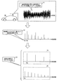
First, the outline of the detection method according to the present invention will be described with reference to FIG. FIG. 1 is a diagram showing an outline of a detection method according to the present invention. The detection method shown in FIG. 1 detects each signal included in a signal group from data in which signal groups having different base frequencies are superimposed.
なお、図1では、移動体Mが自動車である場合を例にとって示しているが、移動体Mは自動車に限られない。たとえば、移動体Mは、電車や船舶、航空機などの、利用者が乗車、搭乗または操縦等するものであってもよい。 In addition, although the case where the mobile body M is an automobile is shown as an example in FIG. 1, the mobile body M is not limited to an automobile. For example, the moving body M may be a vehicle, boarding or maneuvering of a user such as a train, a ship, and an aircraft.
また、以下では、説明の便宜上、基底周波数が異なる信号群の各信号をノイズとして説明するが、かかる信号はノイズに限られない。信号群は、或る信号に重畳された他の信号群であったり、或る信号の一部であったりしてもよい。また、以下では、基底周波数が異なる2つの信号が重畳している場合を例にとって説明するが、かかる信号の数を限定するものではない。また、以下に述べる「周波数スペクトラム」とは、データやデータに含まれる信号について周波数に対する強度(レベル)を示すグラフのことを指す。 In the following, for convenience of explanation, each signal of a signal group having a different base frequency will be described as noise. However, such a signal is not limited to noise. The signal group may be another signal group superimposed on a certain signal, or may be a part of a certain signal. Hereinafter, a case where two signals having different base frequencies are superimposed will be described as an example, but the number of such signals is not limited. In addition, the “frequency spectrum” described below refers to a graph showing the intensity (level) with respect to frequency for data and signals included in the data.
図1に示すように、アンテナ11は、移動体Mに設けられる。アンテナ11は、たとえば到来するラジオ放送等の放送電波や、その他の方式で送信される各種無線電波を受信する。 As shown in FIG. 1, the antenna 11 is provided in the moving body M. The antenna 11 receives, for example, incoming radio waves such as radio broadcasts and various radio waves transmitted by other methods.
ところで、アンテナ11が受信した受信電波には、ノイズが重畳されて受信品質の低下がもたらされることがある。かかるノイズとしては、基底周波数の基本波と基底周波数の2以上の整数倍の周波数の高調波とが複合されたいわゆる「周期性ノイズ」がある。そして、かかる周期性ノイズとしては、たとえば移動体Mがハイブリッド自動車の場合、インバータやDC−DCコンバータといった電力変換装置からのスイッチングノイズなどが挙げられる。 Incidentally, noise may be superimposed on the received radio wave received by the antenna 11 to cause a reduction in reception quality. Such noise includes so-called “periodic noise” in which a fundamental wave having a base frequency and a harmonic having a frequency that is an integer multiple of 2 or more of the base frequency are combined. Examples of such periodic noise include switching noise from a power conversion device such as an inverter or a DC-DC converter when the moving body M is a hybrid vehicle.
ここで、従来は、複数のノイズ信号を含むデータにフーリエ変換の処理を施し、得られた周波数スペクトラムにおけるピーク強度を所定の閾値と比較することによって、ノイズ信号それぞれを検出する手法が一般的であった。 Here, conventionally, a method of detecting each noise signal by performing Fourier transform processing on data including a plurality of noise signals and comparing the peak intensity in the obtained frequency spectrum with a predetermined threshold value is generally used. there were.
しかしながら、このような従来の手法では、周波数スペクトラムにおけるノイズ信号とその他の信号とのピーク強度の差が小さい場合、適切な閾値を設定することが難しく、ノイズの検出精度が低下するおそれがあった。また、かかる閾値の設定における困難性は、データが複数のノイズ信号を含む場合にさらに大きなものとなる。また、従来の手法では、周波数スペクトラムにおけるピーク強度を比較しているため、さまざまな強度の周波数成分を含む周期性ノイズを精度よく検出することが難しかった。 However, in such a conventional method, when the difference in peak intensity between the noise signal and other signals in the frequency spectrum is small, it is difficult to set an appropriate threshold value, and noise detection accuracy may be reduced. . Further, the difficulty in setting the threshold value is even greater when the data includes a plurality of noise signals. Further, in the conventional method, since peak intensities in frequency spectra are compared, it is difficult to accurately detect periodic noise including frequency components having various intensities.
そこで、本発明に係る検出方法では、データにおける周期性ノイズの基底周波数を算出し、算出した基底周波数に基づいて各周期性ノイズを検出することとした。これにより、データが複数の周期性ノイズを含む場合であっても、かかる周期性ノイズの検出精度を向上させることができる。 Therefore, in the detection method according to the present invention, the base frequency of the periodic noise in the data is calculated, and each periodic noise is detected based on the calculated base frequency. As a result, even when the data includes a plurality of periodic noises, it is possible to improve the detection accuracy of such periodic noises.
以下では、本発明に係る検出方法を実行する手順について説明する。本発明に係る検出方法では、移動体Mに設けられたアンテナ11を介して基底周波数が異なる周期性ノイズ(信号群)がそれぞれ重畳されたデータを取得する(ステップS1)。 Below, the procedure which performs the detection method which concerns on this invention is demonstrated. In the detection method according to the present invention, data on which periodic noises (signal groups) having different base frequencies are superimposed is obtained via the antenna 11 provided in the moving body M (step S1).
つづいて、本発明に係る検出方法では、データをフーリエ変換して得られた周波数スペクトラムに基づいて、それぞれの周期性ノイズの基底周波数(図1の「基底周波数BaおよびBb」参照)を算出する(ステップS2)。なお、ここに示した基底周波数の検出方法の詳細については、図4および図5を用いて後述する。 Subsequently, in the detection method according to the present invention, the base frequency of each periodic noise (see “base frequencies Ba and Bb” in FIG. 1) is calculated based on the frequency spectrum obtained by Fourier transforming the data. (Step S2). The details of the base frequency detection method shown here will be described later with reference to FIGS.
そして、本発明に係る検出方法では、算出した基底周波数BaおよびBbに基づいて複数の周期性ノイズそれぞれを検出する(ステップS3)。なお、図1には、基底周波数Baの周期性ノイズを信号群Saとして示し、基底周波数Bbの周期性ノイズを信号群Sbとして示している。また、ここに示した周期性ノイズの検出方法の詳細については、図6等を用いて後述する。 In the detection method according to the present invention, each of the plurality of periodic noises is detected based on the calculated base frequencies Ba and Bb (step S3). In FIG. 1, the periodic noise at the base frequency Ba is shown as a signal group Sa, and the periodic noise at the base frequency Bb is shown as a signal group Sb. The details of the periodic noise detection method shown here will be described later with reference to FIG.
このように、本発明に係る検出方法は、基底周波数が異なる信号群がそれぞれ重畳されたデータから周期性ノイズの基底周波数を算出し、算出した基底周波数に基づいて各周期性ノイズを検出する。したがって、本発明に係る検出方法によれば、データに重畳されたノイズ信号などの信号を精度よく検出することができる。 As described above, the detection method according to the present invention calculates the base frequency of periodic noise from data in which signal groups having different base frequencies are superimposed, and detects each periodic noise based on the calculated base frequency. Therefore, according to the detection method of the present invention, a signal such as a noise signal superimposed on data can be detected with high accuracy.
以下では、図1を用いて説明した検出方法の詳細、および、かかる検出方法を適用した検出装置および受信装置についての実施形態を詳細に説明する。なお、以下では、受信装置が、図1を用いて説明した、いわゆる自動車に設けられたノイズ検出装置を含む場合を例にとって説明する。 Hereinafter, details of the detection method described with reference to FIG. 1 and embodiments of a detection device and a reception device to which the detection method is applied will be described in detail. In the following, a case where the receiving device includes a noise detection device provided in a so-called automobile described with reference to FIG. 1 will be described as an example.
<2.受信装置の構成>
図2は、本実施形態に係る受信装置1の内部構成を示すブロック図である。なお、同図では、受信装置1の特徴を説明するために必要な構成要素のみを示しており、一般的な構成要素についての記載を省略している。
<2. Configuration of receiving device>
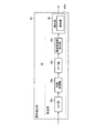
FIG. 2 is a block diagram showing an internal configuration of the
図2に示す受信装置1は、たとえばラジオ放送やテレビ放送等の放送電波を受信するAM放送受信機やFM放送受信機等の受信装置に相当し、アンテナ11およびスピーカ18に接続される。受信装置1は、検出装置2、IFノイズ処理部14、IF処理部15、オーディオ周波数変換部16およびオーディオ処理部17を備える。検出装置2は、取得部21および信号検出部22を備える。取得部21は、フロントエンド部12およびA/D変換部13を備える。
The
取得部21は、基底周波数が異なる周期性ノイズがそれぞれ重畳されたデータを、アンテナ11を介して取得する。具体的には、フロントエンド部12は、アンテナ11で受信した放送電波を中間周波数信号(以下、単に「IF信号」と称する)に変換する。A/D変換部13は、かかるIF信号をデジタル変換する。なお、ここではA/D変換部13が
IF信号をデジタル変換することとしたが、これに限らず、A/D変換部13は、IF変換前のRF信号をデジタル変換することとしてもよい。
The
また、信号検出部22は、A/D変換部13経由で順次取得するIF信号(すなわちデータ)のうち周期性ノイズを検出する。そして、信号検出部22は、周期性ノイズの基底周波数を含む信号をIFノイズ処理部14へ出力する。なお、信号検出部22が実行する処理の詳細については図3〜図6を用いて後述する。
Further, the
IFノイズ処理部14は、信号検出部22からの信号に基づいて、デジタル化されたIF信号のノイズ成分を除去するブランク処理を実行する。なお、ブランク処理とは、IF信号の連続する信号区間のうち、ノイズ成分を含む除去対象区間を除去し、かかる除去した区間を信号補間する補間処理に相当する。
The IF
IF処理部15は、デジタル化されたIF信号に対してデジタルフィルタ処理を実行する。なお、デジタルフィルタ処理は、到来する放送電波の放送周波数と隣接する隣接放送周波数のIF信号を妨害信号として除去するフィルタ処理に相当する。
The
オーディオ周波数変換部16は、デジタルフィルタを施したIF信号をオーディオ周波数信号(以下、単に「オーディオ信号」と称する)に変換する。オーディオ処理部17は、オーディオ信号に対してオーディオ処理を実行する。なお、オーディオ処理とは、音声ミュート処理や高周波成分を除去するハイカット処理等に相当する。スピーカ18は、オーディオ処理を施したオーディオ信号を音響出力する。なお、A/D変換部13から後段のオーディオ処理部17までの各種部位は、たとえばデジタルシグナルプロセッサ(DSP)で構成するが、DSPに限定するものではない。
The audio
なお、上述したIF変換は必ずしも必要ではなくフロントエンド部で必要な周波数を取り出す処理を行うこととしても良い。この場合の必要周波数はAM帯やFM帯、テレビ帯全体といったある程度広い周波数範囲に相当する。 Note that the above-described IF conversion is not always necessary, and a process of extracting a necessary frequency in the front end unit may be performed. The necessary frequency in this case corresponds to a certain wide frequency range such as the AM band, the FM band, and the entire television band.
<3.信号検出部の構成および検出処理の具体的動作>
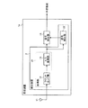
以下では、信号検出部22の構成および信号検出部22が実行する処理の詳細について図3〜図6を用いて説明する。図3は、信号検出部22の内部構成を示すブロック図である。図4および図5は、各信号の検出方法を説明するための説明図(その1)および(その2)である。図6は、検出部が検出する信号群の一例を示す図である。なお、以下に述べるフーリエ変換には、離散化された情報を取り扱うDFT(Discrete Fourier Transform)も含まれるものとする。また、以下では、データに2つの周期性ノイズが重畳されている場合を例にとって説明するが、データに重畳される周期性ノイズが3つ以上であってもよい。
<3. Configuration of Signal Detection Unit and Specific Operation of Detection Processing>
Below, the structure of the
図3に示す信号検出部22は、算出部30および検出部40を備える。算出部30は、FFT(Fast Fourier Transform)部30a、対数変換部30b、IFFT(Inverse Fast Fourier Transform)部30cおよび基底周波数算出部30dを備える。
The
算出部30は、デジタル化されたIF信号のうち、たとえば放送電波における搬送波の周波数成分を除いた信号に、いわゆる「ケプストラム演算処理」を施す。ここで、ケプストラム演算とは、複数の信号が重畳された信号に対して、各信号を分離させる解析を実行する信号処理演算のことを指す。算出部30は、IF信号に、フーリエ変換、対数変換および逆フーリエ変換の処理を順次施すことによって、ケプストラム演算処理を実行する。
The
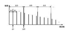
具体的には、FFT部30aは、図4に示すように、IF信号のうち搬送波の周波数成分を除いた信号にフーリエ変換の処理を施して周波数スペクトラムを算出し、対数変換部30bへ出力する。なお、図4における周波数スペクトラムの縦軸は「スペクトラムの強度(レベル)」(以下、「強度」と称する)を示し、横軸は周波数を示している。なお、図4には、基底周波数がそれぞれΔIおよびΔD(>ΔI)である2つの周期性ノイズが重畳している場合を例にとって示している。
Specifically, as shown in FIG. 4, the
ここで、周期性ノイズにおける高調波成分の各周波数は基底周波数の2以上の整数倍になる。したがって、周期性ノイズは、周波数スペクトラムにおいて周波数の間隔がそれぞれ基底周波数に等しいピーク群として示される。また、各周期性ノイズのそれぞれのピーク強度は、周波数の増加とともに順次減少する。 Here, each frequency of the harmonic component in the periodic noise is an integer multiple of 2 or more of the base frequency. Therefore, periodic noise is shown as a peak group in which the frequency interval is equal to the base frequency in the frequency spectrum. In addition, each peak intensity of each periodic noise decreases sequentially as the frequency increases.
具体的には、図4に示すように、基底周波数ΔIから周波数の間隔がΔIで並びつつ周波数の増加とともに強度が順次減少するピーク群と、基底周波数ΔDから周波数の間隔がΔDで並びつつ周波数の増加とともに強度が順次減少するピーク群とが重畳する。 Specifically, as shown in FIG. 4, a peak group in which the frequency interval is arranged with ΔI from the base frequency ΔI and the intensity sequentially decreases as the frequency increases, and the frequency with the frequency interval arranged from the base frequency ΔD with the frequency ΔD. A peak group in which the intensity decreases with increasing increases.
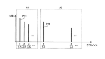
対数変換部30bは、周波数スペクトラムに、2乗処理や絶対値化の処理の後に対数変換の処理を施して「対数振幅スペクトラム」を算出し、IFFT部30cへ出力する。IFFT部30cは、対数振幅スペクトラムに逆フーリエ変換の処理を施して「ケプストラムの値」(以下、「C値」と称する)を算出し、基底周波数算出部30dへ出力する。なお、以下の説明において「ケプストラム」とは、図5に示すように、上記のC値を時間の次元を有する変数(すなわちケフレンシ)に対して示したグラフのことを指す。すなわち、図5に示すケプストラムの縦軸はC値を示し、横軸はケフレンシを示している。
The
そして、ケプストラムにおいて、周期性の信号は、かかる周期性の信号における基底周波数の逆数のケフレンシから等間隔に並びつつ、ケフレンシの増加とともにC値が順次減少するピーク群に変換される。また、かかるピークどうしの間隔は、周期性の信号における基底周波数の逆数に等しい。 Then, in the cepstrum, the periodic signal is converted into a peak group in which the C value sequentially decreases as the quefrenency increases while being arranged at equal intervals from the kerfrenzy of the reciprocal of the base frequency in the periodic signal. The interval between the peaks is equal to the reciprocal of the base frequency in the periodic signal.
具体的には、図5に示すように、周波数スペクトラムにおいて基底周波数がΔIの周期性ノイズは、ケフレンシ1/ΔIから間隔が1/ΔIで並びつつ、ケフレンシの増加とともにC値が順次減少するピーク群に変換される。また、周波数スペクトラムにおいて基底周波数がΔDの周期性ノイズは、ケフレンシ1/ΔDから間隔が1/ΔDで並びつつ、ケフレンシの増加とともにC値が順次減少するピーク群に変換される。すなわち、ケプストラム演算処理によれば、基底周波数が異なる周期性ノイズのピーク群を、それぞれケフレンシが離れた位置へ分離することができる。図5には、このように分離された2つの周期性ノイズをそれぞれ信号グループA1およびA2として示している。
Specifically, as shown in FIG. 5, periodic noise having a base frequency of ΔI in the frequency spectrum is a peak in which the C value sequentially decreases as the quefrency increases while the interval is 1 / ΔI from the
また、上述したように、ケプストラム演算処理によれば、ケフレンシが1/ΔIおよび1/ΔDのピークは、それぞれが属するピーク群においてC値が最も大きいピークとなる。そこで、基底周波数算出部30dは、信号グループA1およびA2の各信号のうちC値が最も大きいピーク(図5の「ピークP11およびP21」参照)のケフレンシから基底周波数を算出することとした。これにより、各周期性ノイズの基底周波数を精度よく算出することができる。 Further, as described above, according to the cepstrum calculation process, the peaks having the quefrency of 1 / ΔI and 1 / ΔD are the peaks having the largest C value in the peak group to which each belongs. Therefore, the base frequency calculation unit 30d calculates the base frequency from the quefrency of the peak having the largest C value (see “peaks P11 and P21” in FIG. 5) among the signals of the signal groups A1 and A2. Thereby, the base frequency of each periodic noise can be calculated with high accuracy.
なお、各信号グループA1およびA2からC値が最も大きいピークを検出する方法としては、たとえばケフレンシの小さい方から順にピークのC値を比較していく方法が挙げられる。具体的には、隣接する二つのピークを比較し、ケフレンシが大きいピークのC値がケフレンシの小さいピークのC値より所定値以上大きい場合に、ケフレンシが大きいピークを信号グループA1およびA2の最大ピークとする。 In addition, as a method of detecting the peak having the largest C value from each of the signal groups A1 and A2, for example, a method of comparing the C values of the peaks in order from the smallest quefrency is mentioned. Specifically, two adjacent peaks are compared, and when the C value of a peak with a high kerfrenency is greater than a C value of a peak with a low kerfrenity by a predetermined value or more, the peak with a high kerflenency is designated as the maximum peak of the signal groups A1 and A2. And
また、ケフレンシから周波数への変換は、ケフレンシの逆数をとってもよいし、ケプストラムの一部にフーリエ変換を含む処理を施して対数振幅スペクトラムや周波数スペクトラムへ逆変換することとしてもよい。 Further, the conversion from quefrency to frequency may take the reciprocal of quefrency, or may perform inverse conversion to a logarithmic amplitude spectrum or frequency spectrum by applying a process including Fourier transform to a part of the cepstrum.
このように、実施形態に係る検出装置2では、移動体Mに設けられたアンテナ11を介して取得したデータにケプストラム演算処理を施す。これにより、複雑でなく処理能力を要しない演算によって複数の周期性ノイズをそれぞれ分離することが可能となる。すなわち、簡便な処理で各周期性ノイズの検出精度を向上させることができる。
Thus, in the
また、実施形態に係る検出装置2は、周期性ノイズの基底周波数を最初に検出する。これにより、周期性ノイズの周波数が変動しても、かかる変動に追従しつつ各周期性ノイズを検出することが可能となる。したがって、周期性ノイズの周波数が、たとえばハイブリッド自動車における電力変換装置のスイッチングノイズのように動作状態等により変動しても、かかる変動に追従しつつ周期性ノイズを精度よく検出することができる。
Moreover, the
なお、かかる電力変換装置としては、たとえば電力を直流−交流の間で変換するインバータや、入力された直流電力を、所定の電圧に昇降圧された直流電力に変換するDC−DCコンバータなどが挙げられる。 Examples of such a power converter include an inverter that converts power between DC and AC, and a DC-DC converter that converts input DC power into DC power that is stepped up and down to a predetermined voltage. It is done.
また、実施形態に係る検出装置2によれば、ノイズ源を問わない。したがって、上記したスイッチングノイズに限らず、たとえば電気回路のフロアノイズやエンジンからのノイズなどに含まれる周期性ノイズを検出することができる。また、移動体Mの外部にあるノイズ源からの周期性ノイズも検出することができる。
Moreover, according to the
次に、検出部40が実行する処理について説明する。図3に示す検出部40は、基底周波数算出部30dで算出された基底周波数に対して逓倍処理を施し、基底周波数を含む信号とともにIFノイズ処理部14(図2参照)へ出力する。ここで、逓倍処理とは、基底周波数を2以上の整数倍する処理のことを指す。かかる逓倍処理は、検出部40の逓倍部40Aによって実行される。
Next, processing executed by the
逓倍部40Aは、基底周波数算出部30dで算出された基底周波数ΔIおよびΔDをそれぞれ2以上の整数倍して、逓倍後の周波数2ΔI、3ΔI・・・および2ΔD、3ΔD・・・を算出する。すなわち、基底周波数ΔIおよびΔDの基本波に対する高調波成分の周波数を算出する。そして、検出部40は、基底周波数ΔIおよびΔDとともに基底周波数ΔIおよびΔDの高調波成分の周波数(すなわち逓倍後の周波数2ΔI、3ΔI・・・および2ΔD、3ΔD・・・)をIFノイズ処理部14へ出力する。
The
IFノイズ処理部14は、検出部40で検出された周波数成分をIF信号から除去し、ブランク処理を実行する。なお、IFノイズ処理部14は、たとえばノッチフィルタを含んで構成することができる。
The IF
このように、実施形態に係る検出装置2では、各信号の基底周波数へ逓倍処理を施す。これにより、簡便な処理で周波数の帯域全体における信号の周波数を検出することが可能となる。したがって、周波数帯域の全体を走査して信号の周波数を検出する場合と比較して装置や回路を簡素化することができる。
Thus, in the
なお、上記した例では、基底周波数算出部30dが周期性ノイズの基底周波数を算出する場合を例にとって説明した。しかしながら、これに限らず、基底周波数算出部30dは、算出された基底周波数の強度をさらに算出することとしてもよい。かかる強度の算出は、たとえば、図5に示したピークP11およびP21のC値を強度(図4の縦軸参照)へ変換することで行われる。 In the above example, the case where the base frequency calculation unit 30d calculates the base frequency of the periodic noise has been described as an example. However, the present invention is not limited to this, and the base frequency calculation unit 30d may further calculate the intensity of the calculated base frequency. The calculation of the intensity is performed, for example, by converting the C values of the peaks P11 and P21 shown in FIG. 5 into the intensity (see the vertical axis in FIG. 4).
この場合、検出部40は、上記した逓倍処理によって得られた各周波数に対応する強度を、基底周波数算出部30dと同様の手順で検出する。そして、検出部40は、基底周波数算出部30dで算出された基底周波数および強度の組とともに、各周波数および強度の組をIFノイズ処理部14へ出力する。
In this case, the
IFノイズ処理部14は、たとえば、受け取った周波数における強度をIF信号から差し引くことによって周期性ノイズを除去する。これにより、IF信号から効率よく周期性ノイズを除去することができる。なお、上記したC値から強度への変換は、ケプストラムにフーリエ変換の処理を施すことによって実行することができる。
The IF
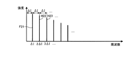
図6には、信号検出部22が信号グループA2の周波数および強度を検出した場合の周波数スペクトラムを、ピークF21、H22、H23・・・として示している。なお、図6に示す信号群は、図4に示した周波数スペクトラムから基底周波数ΔIの周期性ノイズを抽出したものに相当する。
FIG. 6 shows the frequency spectrum when the
次に、本実施形態に係る検出装置2が実行する処理手順について図7を用いて説明する。図7は、本実施形態に係る検出装置2が実行する処理手順を示すフローチャートである。同図に示すように、取得部21が、移動体Mに設けられたアンテナ11を介して基底周波数が異なる信号群がそれぞれ重畳されたデータを取得する(ステップS201)。
Next, a processing procedure executed by the
そして、算出部30は、取得部21が取得したデータに対してケプストラム演算処理を施し(ステップS202)、各信号に対応するピーク群のそれぞれからC値(ケプストラム値)が最も大きいピークの周波数を検出する(ステップS203)。つづいて、検出部40は、算出部30で算出されたC値が最も大きいピークの周波数のそれぞれに逓倍処理を施し(ステップS204)、処理を終了する。
Then, the
なお、上述した処理例では、搬送波の周波数成分を除いたIF信号にケプストラム演算処理を施す場合を例にとって説明した。しかしながら、これに限らず、IF信号に対して搬送波の周波数成分を除かずにケプストラム演算処理を施し、ケプストラムにおいて搬送波を無視してピークを検出することとしてもよい。具体的には、たとえば日本国内におけるAM帯の搬送波は9K(Hz)間隔であるので、ケプストラムにおけるケフレンシの間隔が1/9K(1/Hz)のピーク群を無視してピークの検出を行うこととすればよい。これにより、搬送波の周波数成分を除くためのフィルタ処理を省略することができ、算出部30の回路を簡素化することができる。
In the processing example described above, the case where cepstrum calculation processing is performed on the IF signal excluding the frequency component of the carrier wave has been described as an example. However, the present invention is not limited to this, and the cepstrum calculation process may be performed on the IF signal without removing the frequency component of the carrier wave, and the peak may be detected by ignoring the carrier wave in the cepstrum. Specifically, for example, AM band carriers in Japan are spaced by 9K (Hz), so that peaks are detected by ignoring peaks having a cepstral interval of 1 / 9K (1 / Hz) in the cepstrum. And it is sufficient. Thereby, the filter process for removing the frequency component of the carrier wave can be omitted, and the circuit of the
<4.変形例に係る受信装置の構成>
ところで、上述してきた実施形態では、受信装置1が、受信したデータから周期性ノイズを除去する場合の例について例示したが、受信装置1は、受信したデータから周期性ノイズを抽出することとしてもよい。そこで、以下では受信装置1の変形例について図8を用いて説明する。
<4. Configuration of receiving apparatus according to modification>
By the way, in embodiment mentioned above, although the example in the case where the
なお、本変形例は、たとえば図2に示した受信装置1の変形例であって、図2等に示した受信装置1と同一の要素には同一の符号を付し、重複する記載を省略する。図8は、変形例に係る受信装置1aの内部構成を示すブロック図である。
In addition, this modification is a modification of the receiving
図8に示すように、変形例に係る受信装置1aは、検出装置2および信号抽出部19を備える。信号抽出部19は、信号検出部22で検出された周期性ノイズの周波数を含む信号に基づいて、周期性ノイズのそれぞれをIF信号から抽出して外部装置へ出力する。なお、外部装置は、たとえば、信号の電気信号を表示するオシロスコープ等である。また、信号抽出部19としては、たとえばLMS(Least Mean Square)アルゴリズムの最適化アルゴリズムを用いた適応フィルタなどを用いることができる。
As illustrated in FIG. 8, the
なお、図6を用いて既に説明したように、変形例に係る受信装置1aにおいても検出装置2は、周期性ノイズの周波数とともに強度を検出することができる。この場合、受信装置1aは、IF信号から各周期性ノイズの周波数とともに強度を抽出することができる。
As already described with reference to FIG. 6, in the receiving
このように変形例に係る受信装置1aでは、検出装置2が検出した信号を、データから抽出することとした。これにより、信号群に含まれる信号をそれぞれ精度よく抽出することができる。
As described above, in the
上述してきたように、実施形態に係る検出装置は、取得部と、算出部と、検出部とを備える。取得部は、基底周波数が異なる信号群がそれぞれ重畳されたデータを移動体に設けられたアンテナを介して取得する。算出部は、取得部によって取得されたデータの周波数スペクトラムに基づいて信号群それぞれの基底周波数を算出する。検出部は、算出部によって算出された基底周波数に基づいて信号群に含まれる各信号をそれぞれ検出する。 As described above, the detection device according to the embodiment includes an acquisition unit, a calculation unit, and a detection unit. The acquisition unit acquires data on which signal groups having different base frequencies are superimposed via an antenna provided in the moving body. The calculation unit calculates the base frequency of each signal group based on the frequency spectrum of the data acquired by the acquisition unit. The detection unit detects each signal included in the signal group based on the base frequency calculated by the calculation unit.
このように、実施形態に係る検出装置は、信号群それぞれの基底周波数に基づいて信号群に含まれる各信号を検出する。したがって、実施形態に係る検出装置によれば、信号群に含まれる各信号の検出精度を向上させることができる。 Thus, the detection apparatus according to the embodiment detects each signal included in the signal group based on the base frequency of each signal group. Therefore, according to the detection apparatus according to the embodiment, the detection accuracy of each signal included in the signal group can be improved.
また、上記した実施形態では、IF信号のノイズ成分を除去する際にブランク処理を採用したが、ノイズ成分を除去する他の処理方法を採用したとしても同様の効果が得られることは言うまでもない。また、上記した実施形態では、ラジオ受信機を例に挙げて説明したが、テレビ受信機やビーコン受信機などに採用してもよい。 In the above-described embodiment, the blank process is adopted when removing the noise component of the IF signal. However, it goes without saying that the same effect can be obtained even if another processing method for removing the noise component is adopted. In the above-described embodiment, the radio receiver has been described as an example. However, the radio receiver may be employed in a television receiver or a beacon receiver.
また、上記した実施形態では、基底周波数が異なる信号群の各信号をノイズとして説明した。しかしながら、これに限らず、信号群は、或る信号に重畳された他の信号群であったり、或る信号の一部であったりしてもよい。また、データに含まれる基底周波数が異なる信号の数は3つ以上であってもよい。 In the above-described embodiment, each signal of a signal group having a different base frequency has been described as noise. However, the present invention is not limited to this, and the signal group may be another signal group superimposed on a certain signal, or may be a part of a certain signal. Further, the number of signals having different base frequencies included in the data may be three or more.
また、図示した各部の各構成要素は、必ずしも物理的に図示のごとく構成されていることを要しない。すなわち、各部の分散・統合の具体的形態は図示のものに限られず、その全部または一部を、各種の負荷や使用状況に応じて、任意の単位で機能的または物理的に分散・統合して構成することができる。 In addition, each component of each part illustrated does not necessarily need to be physically configured as illustrated. In other words, the specific form of distribution / integration of each unit is not limited to the one shown in the figure, and all or a part thereof is functionally or physically distributed / integrated in arbitrary units according to various loads and usage conditions. Can be configured.
さらなる効果や変形例は、当業者によって容易に導き出すことができる。このため、本発明のより広範な態様は、以上のように表しかつ記述した特定の詳細および代表的な実施形態に限定されるものではない。したがって、添付の特許請求の範囲およびその均等物によって定義される総括的な発明の概念の精神または範囲から逸脱することなく、様々な変更が可能である。 Further effects and modifications can be easily derived by those skilled in the art. Thus, the broader aspects of the present invention are not limited to the specific details and representative embodiments shown and described above. Accordingly, various modifications can be made without departing from the spirit or scope of the general inventive concept as defined by the appended claims and their equivalents.
1、1a 受信装置
2 検出装置
11 アンテナ
14 IFノイズ処理部
19 信号抽出部
21 取得部
22 信号検出部
30 算出部
30a FFT部
30b 対数変換部
30c IFFT部
30d 基底周波数算出部
40 検出部
40A 逓倍部
M 移動体
Sa、Sb 信号群
A1、A2 信号グループ
DESCRIPTION OF
Claims (6)
前記取得部によって取得されたデータの周波数スペクトラムに基づいて前記信号群それぞれの前記基底周波数を算出する算出部と、
前記算出部によって算出された前記基底周波数に基づいて前記信号群に含まれる各信号をそれぞれ検出する検出部と
を備え、
前記算出部は、
各信号群の中の最も大きいピークに対応する各基底周波数を算出し、
前記検出部は、
各信号群の基底周波数の基本波と、基底周波数の2以上の整数倍の周波数の高調波とを前記信号群に含まれる各信号として検出する
ことを特徴とする検出装置。 An acquisition unit for acquiring data in which signal groups having different base frequencies are superimposed via an antenna provided on the moving body;
A calculation unit that calculates the base frequency of each of the signal groups based on the frequency spectrum of the data acquired by the acquisition unit;
A detection unit that detects each signal included in the signal group based on the base frequency calculated by the calculation unit , and
The calculation unit includes:
Calculate each base frequency corresponding to the largest peak in each signal group,
The detector is
A detection apparatus that detects a fundamental wave having a base frequency of each signal group and a harmonic having a frequency that is an integer multiple of two or more of the base frequencies as each signal included in the signal group .
前記周波数スペクトラムに対してケプストラム値を算出するケプストラム演算を行うことで前記基底周波数を算出すること
を特徴とする請求項1に記載の検出装置。 The calculation unit includes:
The detection device according to claim 1, wherein the base frequency is calculated by performing a cepstrum calculation for calculating a cepstrum value with respect to the frequency spectrum.
前記信号群ごとに前記ケプストラム値が最も大きいピークに対応する周波数を前記信号群ぞれぞれの前記基底周波数として算出し、
前記検出部は、
前記算出部によって算出された前記基底周波数に対して逓倍処理を施すことで前記信号群に含まれる各信号をそれぞれ検出すること
を特徴とする請求項2に記載の検出装置。 The calculation unit includes:
Calculating the frequency corresponding to the peak with the largest cepstrum value for each signal group as the base frequency of each of the signal groups;
The detector is
The detection apparatus according to claim 2, wherein each signal included in the signal group is detected by performing a multiplication process on the base frequency calculated by the calculation unit.
前記検出装置によって検出された前記各信号を前記データから抽出する抽出部と
を備えることを特徴とする受信装置。 The detection device according to any one of claims 1 to 3,
The receiving apparatus, comprising: an extraction unit that extracts each signal detected by the detection apparatus from the data.
前記検出装置によって検出された前記各信号を前記データから除去する除去部と
を備えることを特徴とする受信装置。 The detection device according to any one of claims 1 to 3,
A receiving device, comprising: a removing unit that removes each signal detected by the detecting device from the data.
前記取得工程によって取得されたデータの周波数スペクトラムに基づいて前記信号群それぞれの前記基底周波数を算出する算出工程と、
前記算出工程によって算出された前記基底周波数に基づいて前記信号群に含まれる各信号をそれぞれ検出する検出工程と
を含み、
前記算出工程は、
各信号群の中の最も大きいピークに対応する各基底周波数を算出し、
前記検出工程は、
各信号群の基底周波数の基本波と、基底周波数の2以上の整数倍の周波数の高調波とを前記信号群に含まれる各信号として検出する
ことを特徴とする検出方法。 An acquisition step of acquiring data in which signal groups having different base frequencies are superimposed via an antenna provided on the moving body;
A calculation step of calculating the base frequency of each of the signal groups based on the frequency spectrum of the data acquired by the acquisition step;
Look including a detection step of detecting each signal included in the signal group based on the base frequency calculated by said calculation step respectively,
The calculation step includes
Calculate each base frequency corresponding to the largest peak in each signal group,
The detection step includes
A detection method comprising: detecting a fundamental wave having a base frequency of each signal group and a harmonic having a frequency that is an integer multiple of two or more of the base frequencies as each signal included in the signal group .
Priority Applications (3)
| Application Number | Priority Date | Filing Date | Title |
|---|---|---|---|
| JP2015109097A JP6232012B2 (en) | 2015-05-28 | 2015-05-28 | Detection device, reception device, and detection method |
| DE102016109202.9A DE102016109202B4 (en) | 2015-05-28 | 2016-05-19 | Recognition device, receiving device and recognition method |
| US15/160,599 US9900035B2 (en) | 2015-05-28 | 2016-05-20 | Detection apparatus, receiving apparatus, and detection method |
Applications Claiming Priority (1)
| Application Number | Priority Date | Filing Date | Title |
|---|---|---|---|
| JP2015109097A JP6232012B2 (en) | 2015-05-28 | 2015-05-28 | Detection device, reception device, and detection method |
Publications (2)
| Publication Number | Publication Date |
|---|---|
| JP2016225759A JP2016225759A (en) | 2016-12-28 |
| JP6232012B2 true JP6232012B2 (en) | 2017-11-15 |
Family
ID=57281698
Family Applications (1)
| Application Number | Title | Priority Date | Filing Date |
|---|---|---|---|
| JP2015109097A Expired - Fee Related JP6232012B2 (en) | 2015-05-28 | 2015-05-28 | Detection device, reception device, and detection method |
Country Status (3)
| Country | Link |
|---|---|
| US (1) | US9900035B2 (en) |
| JP (1) | JP6232012B2 (en) |
| DE (1) | DE102016109202B4 (en) |
Cited By (1)
| Publication number | Priority date | Publication date | Assignee | Title |
|---|---|---|---|---|
| JP2829396B2 (en) | 1989-08-14 | 1998-11-25 | 株式会社ホリキリ | Leaf spring for vehicles |
Families Citing this family (3)
| Publication number | Priority date | Publication date | Assignee | Title |
|---|---|---|---|---|
| JP6232012B2 (en) * | 2015-05-28 | 2017-11-15 | 富士通テン株式会社 | Detection device, reception device, and detection method |
| US9990035B2 (en) | 2016-03-14 | 2018-06-05 | Robert L. Richmond | Image changes based on viewer's gaze |
| JP2024112669A (en) * | 2023-02-08 | 2024-08-21 | 株式会社日立製作所 | COMPUTER SYSTEM, NOISE SEPARATION METHOD, AND PROGRAM |
Family Cites Families (12)
| Publication number | Priority date | Publication date | Assignee | Title |
|---|---|---|---|---|
| JPS61186037A (en) * | 1985-02-14 | 1986-08-19 | Radio Res Lab | System for measuring ssb transmission frequency |
| JPH083525B2 (en) | 1988-10-12 | 1996-01-17 | 日本無線株式会社 | CPS receiver |
| JP3106829B2 (en) | 1993-12-22 | 2000-11-06 | 松下電器産業株式会社 | GPS receiver demodulation circuit |
| JP3593697B2 (en) * | 2001-11-22 | 2004-11-24 | 理化工業株式会社 | Noise canceling device |
| US6984960B2 (en) * | 2003-08-05 | 2006-01-10 | General Motors Corporation | Methods and apparatus for current control of a three-phase voltage source inverter in the overmodulation region |
| FR2892202B1 (en) * | 2005-10-14 | 2007-11-30 | Thales Sa | IMPROVED PRECISION GNSS RECEIVER USING TWO SIGNAL CARRIERS |
| KR100772927B1 (en) * | 2006-09-29 | 2007-11-02 | 한국전자통신연구원 | Heterodyne RF Transceiver for Radar Sensor |
| JP4535145B2 (en) | 2008-02-26 | 2010-09-01 | ソニー株式会社 | Communication device, noise removal method, and program |
| JP2010096635A (en) * | 2008-10-16 | 2010-04-30 | Advantest Corp | Distortion identification device, test system, program, and distortion identification method |
| EP2383896B1 (en) * | 2010-04-30 | 2013-07-31 | Alcatel Lucent | Methods and devices for detecting electromagnetic interference on data transmission lines |
| US9020080B2 (en) * | 2011-06-16 | 2015-04-28 | Lockheed Martin Corporation | Method and system to adaptively cancel sinusoidal interference from a signal processing system |
| JP6232012B2 (en) * | 2015-05-28 | 2017-11-15 | 富士通テン株式会社 | Detection device, reception device, and detection method |
-
2015
- 2015-05-28 JP JP2015109097A patent/JP6232012B2/en not_active Expired - Fee Related
-
2016
- 2016-05-19 DE DE102016109202.9A patent/DE102016109202B4/en active Active
- 2016-05-20 US US15/160,599 patent/US9900035B2/en active Active
Cited By (1)
| Publication number | Priority date | Publication date | Assignee | Title |
|---|---|---|---|---|
| JP2829396B2 (en) | 1989-08-14 | 1998-11-25 | 株式会社ホリキリ | Leaf spring for vehicles |
Also Published As
| Publication number | Publication date |
|---|---|
| DE102016109202A1 (en) | 2016-12-01 |
| DE102016109202B4 (en) | 2019-11-07 |
| US20160352371A1 (en) | 2016-12-01 |
| JP2016225759A (en) | 2016-12-28 |
| US9900035B2 (en) | 2018-02-20 |
Similar Documents
| Publication | Publication Date | Title |
|---|---|---|
| CN102075484B (en) | Method and device for reducing peak-to-average power ratio of signal | |
| JP6232012B2 (en) | Detection device, reception device, and detection method | |
| CN113472372B (en) | Noise suppression device, noise suppression method, reception device, and reception method | |
| JP6426559B2 (en) | Method of correcting frequency reception signal, correction device of frequency reception signal, noise canceling method for vehicle, and noise canceling device for vehicle | |
| US8995589B1 (en) | Channel estimation in a pilot assisted OFDM system | |
| JP5724668B2 (en) | In-vehicle radio noise reduction system | |
| JP2017129741A (en) | Noise reduction device and noise reduction method | |
| US10263653B1 (en) | Noise reduction device and noise reduction method | |
| US20230088440A1 (en) | Signal processor for a radio receiver | |
| JP2012191413A (en) | Receiving device and signal determination program | |
| EP3617745B1 (en) | Radar device | |
| JP2018110296A (en) | Noise detection apparatus and noise detection method | |
| Sugawara et al. | Electric Vehicle Testing and Verification of Electromagnetic Noise Suppression by Signal Processing in AM Radio | |
| EP3890193B1 (en) | Processing amplitude modulation signals with noise estimation | |
| EP4693908A1 (en) | Amplitude-modulated signal processing method and receiver for an amplitude-modulated signal | |
| RU2776969C1 (en) | Method for extracting a useful component from an input signal containing a useful component and noise | |
| KR101162178B1 (en) | A Signal Process Method for improving S/N of Ion Cyclotron Resonance Mass Spectrometer | |
| JP6456703B2 (en) | Noise canceling device for vehicles | |
| JP6670117B2 (en) | Reception support device and reception support method | |
| KR101421987B1 (en) | Spectrum analyzer and method for processing a measured signal | |
| JP2023049539A (en) | Receiver and noise removal method | |
| JP2010062945A (en) | Wireless reception device and demodulation method | |
| JP2016116399A (en) | Electronic circuit | |
| JP2012151619A (en) | Device and method for voice signal conversion, and receiving device | |
| JP2014179692A (en) | Cell search device and cell search method |
Legal Events
| Date | Code | Title | Description |
|---|---|---|---|
| A977 | Report on retrieval |
Free format text: JAPANESE INTERMEDIATE CODE: A971007 Effective date: 20170425 |
|
| A131 | Notification of reasons for refusal |
Free format text: JAPANESE INTERMEDIATE CODE: A131 Effective date: 20170530 |
|
| A521 | Request for written amendment filed |
Free format text: JAPANESE INTERMEDIATE CODE: A523 Effective date: 20170725 |
|
| TRDD | Decision of grant or rejection written | ||
| A01 | Written decision to grant a patent or to grant a registration (utility model) |
Free format text: JAPANESE INTERMEDIATE CODE: A01 Effective date: 20171003 |
|
| A61 | First payment of annual fees (during grant procedure) |
Free format text: JAPANESE INTERMEDIATE CODE: A61 Effective date: 20171020 |
|
| R150 | Certificate of patent or registration of utility model |
Ref document number: 6232012 Country of ref document: JP Free format text: JAPANESE INTERMEDIATE CODE: R150 |
|
| R250 | Receipt of annual fees |
Free format text: JAPANESE INTERMEDIATE CODE: R250 |
|
| R250 | Receipt of annual fees |
Free format text: JAPANESE INTERMEDIATE CODE: R250 |
|
| R250 | Receipt of annual fees |
Free format text: JAPANESE INTERMEDIATE CODE: R250 |
|
| LAPS | Cancellation because of no payment of annual fees |