JP6231918B2 - Battery system and manufacturing method thereof - Google Patents
Battery system and manufacturing method thereof Download PDFInfo
- Publication number
- JP6231918B2 JP6231918B2 JP2014061506A JP2014061506A JP6231918B2 JP 6231918 B2 JP6231918 B2 JP 6231918B2 JP 2014061506 A JP2014061506 A JP 2014061506A JP 2014061506 A JP2014061506 A JP 2014061506A JP 6231918 B2 JP6231918 B2 JP 6231918B2
- Authority
- JP
- Japan
- Prior art keywords
- battery
- elastic
- plate
- elastic plate
- battery stack
- Prior art date
- Legal status (The legal status is an assumption and is not a legal conclusion. Google has not performed a legal analysis and makes no representation as to the accuracy of the status listed.)
- Active
Links
Images


Classifications
-
- Y—GENERAL TAGGING OF NEW TECHNOLOGICAL DEVELOPMENTS; GENERAL TAGGING OF CROSS-SECTIONAL TECHNOLOGIES SPANNING OVER SEVERAL SECTIONS OF THE IPC; TECHNICAL SUBJECTS COVERED BY FORMER USPC CROSS-REFERENCE ART COLLECTIONS [XRACs] AND DIGESTS
- Y02—TECHNOLOGIES OR APPLICATIONS FOR MITIGATION OR ADAPTATION AGAINST CLIMATE CHANGE
- Y02E—REDUCTION OF GREENHOUSE GAS [GHG] EMISSIONS, RELATED TO ENERGY GENERATION, TRANSMISSION OR DISTRIBUTION
- Y02E60/00—Enabling technologies; Technologies with a potential or indirect contribution to GHG emissions mitigation
- Y02E60/10—Energy storage using batteries
Description
本発明は、複数の電池セルを積層して電池積層ブロックとし、この電池積層ブロックの両端をエンドプレートで押圧して固定しているバッテリシステムとその製造方法に関する。 The present invention relates to a battery system in which a plurality of battery cells are stacked to form a battery stack block, and both ends of the battery stack block are pressed and fixed by end plates, and a method for manufacturing the battery system.
多数の電池セルを積層して電池積層ブロックとし、この電池積層ブロックの両端面に一対のエンドプレートを配置し、両方のエンドプレートを結束具で連結して、積層している電池セルを押圧状態に固定するバッテリシステムは開発されている。(特許文献1参照) A large number of battery cells are stacked to form a battery stack block, a pair of end plates are arranged on both end faces of the battery stack block, both end plates are connected by a binding tool, and the stacked battery cells are pressed. A battery system to be fixed to the battery has been developed. (See Patent Document 1)
このバッテリシステムは、一対のエンドプレートでもって、電池セルを押圧状態に固定している。エンドプレートは、複数の電池セルを積層している電池積層ブロックの両端面に配置されて、電池積層ブロックを加圧する状態で結束具に連結されて、電池積層ブロックを加圧状態に固定する。さらに、隣接する電池セルは、正負の電極端子に金属板のバスバーが固定されて、直列にあるいは並列に接続される。 This battery system fixes a battery cell in a pressed state with a pair of end plates. The end plates are arranged on both end faces of the battery stack block in which a plurality of battery cells are stacked, and are connected to a binding tool in a state in which the battery stack block is pressed to fix the battery stack block in a pressurized state. Further, adjacent battery cells are connected in series or in parallel with a metal plate bus bar fixed to the positive and negative electrode terminals.
ところで、バッテリシステムは、製造工程において発生する電池セルの寸法誤差が原因で、互いに積層される状態で、隣接する電池セルの電極端子の相対位置にずれが生じることがある。隣接する電池セルは、正負の電極端子に金属板のバスバーを溶接し、あるいはネジ止めして固定するので、相対位置がずれるとバスバーを確実に安定して無理なく固定するのが難しくなる。たとえば、電極端子を設けている端子面とその反対側の底面との間の高さに寸法誤差のある電池セルが、底面を同一平面に積層されると、隣接する電池セルの端子面が同一平面に配置されない。隣接する電池セルの端子面を同一平面に配置できない電池積層ブロックは、隣接する電池セルの電極端子が相対的に上下に位置ずれする。上下に位置ずれする端子面の電極端子に、弾性変形しない厚い金属板のバスバーが固定されると、電極端子に無理な応力が作用して、電池セルを損傷する原因となる。 By the way, in the battery system, due to the dimensional error of the battery cells generated in the manufacturing process, the relative positions of the electrode terminals of the adjacent battery cells may be shifted in a state where they are stacked on each other. Adjacent battery cells are fixed by welding or screwing a metal plate bus bar to the positive and negative electrode terminals, so that it is difficult to reliably and securely fix the bus bar when the relative position is shifted. For example, when battery cells with dimensional errors in the height between the terminal surface on which the electrode terminal is provided and the bottom surface on the opposite side are stacked on the same plane, the terminal surfaces of adjacent battery cells are the same It is not placed on a plane. In battery stack blocks in which the terminal surfaces of adjacent battery cells cannot be arranged on the same plane, the electrode terminals of adjacent battery cells are relatively displaced up and down. If a bus bar made of a thick metal plate that is not elastically deformed is fixed to the electrode terminal on the terminal surface that is displaced up and down, excessive stress acts on the electrode terminal, causing damage to the battery cell.
以上の弊害は、たとえば、各々の電池セルの端子面を同一平面に配置する構造で解消できる。このバッテリシステムは、端子面を同一平面に配置する嵌合部を結束具に設けて、各々の電池セルの底面に弾性体を配置して実現できる。嵌合部は、各々の電池セルの端子面の上に配置され、各々の電池セルの端子面をこれに押し付けて同一平面に配置する。電池セルの端子面は、絶縁材を介して、あるいは直接に嵌合部の内面に押し付けられて、同一平面に配置される。弾性体は、各々の電池セルの底面に配置されて、各々の電池セルを弾性的に嵌合部に向かって押圧する。 The above adverse effects can be solved by, for example, a structure in which the terminal surfaces of the respective battery cells are arranged on the same plane. This battery system can be realized by providing a fitting part for arranging the terminal surfaces on the same plane in the binding tool and arranging an elastic body on the bottom surface of each battery cell. A fitting part is arrange | positioned on the terminal surface of each battery cell, presses the terminal surface of each battery cell against this, and arrange | positions on the same plane. The terminal surfaces of the battery cells are arranged on the same plane by being pressed against the inner surface of the fitting portion via an insulating material or directly. An elastic body is arrange | positioned at the bottom face of each battery cell, and presses each battery cell toward a fitting part elastically.
図13のバッテリシステムは、電池積層ブロック902の底面に弾性プレート909を配置する。弾性プレート909は、各々の電池セル901を底面から端子面901Aに向かって弾性的に押圧する弾性押圧部919を設けている。このバッテリシステムは、図において、各弾性押圧部919でもって各電池セル901を独立して弾性的に押し上げている。各々の電池セル901は、絶縁材の絶縁スペーサ905を介して結束具904の嵌合部904Aの下面に端子面901Aを押し付けている。絶縁スペーサ905を介して嵌合部904Aの内面に押し付けられる各電池セル901は、端子面901Aを同一平面に配置して積層される。このバッテリシステムは、弾性押圧部919が電池セル901を弾性的に押し上げ、電池セル901の端子面901Aを結束具904の嵌合部904Aの内面に配置して、各々の電池セル901の端子面901Aを同一平面に配置する。
In the battery system of FIG. 13, an
以上のバッテリシステムは、弾性押圧部で各電池セルを弾性的に押圧するように弾性プレートを配置している。弾性押圧部は、各電池セルの底面に押し付けられている。この弾性プレートは、弾性押圧部を押し潰して弾性変形させる状態で、電池セルを弾性的に押圧する。弾性プレートを電池セルの底面に押し付けるために、図13のバッテリシステムは、結束具904に弾性プレート909を電池積層ブロック902に押し付ける係止部904Bを設けている。係止部904Bは、弾性プレート909の下にあって、弾性押圧部919を押し潰す状態で弾性プレート909を電池積層ブロック902の底面に配置する。以上のバッテリシステムは、弾性プレート909の弾性押圧部919を押し潰す状態で、電池積層ブロック902と弾性プレート909を、結束具904の嵌合部904Aと係止部904Bの間に挿入して、結束具904をエンドプレートに固定する。弾性押圧部を押し潰す状態で、電池積層ブロックと弾性プレートを結束具の嵌合部と係止部の間に入れるには、電池積層ブロックの端子面をジグで押圧して、弾性プレートに向かって押し付けて、弾性押圧部を押し潰し状態に保持し、この状態で電池積層ブロックと弾性プレートを嵌合部と係止部との間に挿入する必要がある。結束具の嵌合部と係止部の間に、電池積層ブロックと弾性プレートを挿入する状態で、嵌合部と係止部は電池セルの両側部をカバーする。したがって、弾性押圧部を押し潰すために、ジグでもって、嵌合部でカバーされる位置で電池積層ブロックを押圧できない。ジグが電池積層ブロックを嵌合部の内側に挿入するのに邪魔になるからである。したがって、このバッテリシステムは、結束具の嵌合部を挿入する位置よりも内側で電池積層体を押圧して弾性押圧部を押し潰して、電池積層ブロックを嵌合部の内側に挿入する必要がある。しかしながら、嵌合部に挿入する位置よりも内側をジグで押圧して、電池積層ブロックを嵌合部の内側に挿入すると、弾性押圧部を押し潰す状態に保持して、電池積層ブロックを嵌合部の内側にスムーズに挿入するのが難しい欠点がある。それは、電池積層ブロックが嵌合部に挿入されない位置で押圧されるので、電池積層ブロックの押圧位置を正確に位置決めできないからである。とくに、端子面の両端部に絶縁スペーサの水平部を配置して、絶縁スペーサの水平部を電池積層ブロックと嵌合部との間に配置するバッテリシステムは、嵌合部の内側に挿入する絶縁スペーサの水平部を押圧できないので、さらに嵌合部の内側に電池積層ブロックを挿入するのが難しくなる欠点がある。
The above battery system arrange | positions the elastic plate so that each battery cell may be elastically pressed by an elastic press part. The elastic pressing portion is pressed against the bottom surface of each battery cell. The elastic plate elastically presses the battery cell in a state where the elastic pressing portion is crushed and elastically deformed. In order to press the elastic plate against the bottom surface of the battery cell, the battery system of FIG. 13 is provided with a
本発明は、さらに以上の欠点を解消することを目的に開発されたもので、本発明の大切な目的は、弾性プレートの弾性押圧部を押し潰す状態に保持して、電池積層ブロックと弾性プレートをスムーズに結束具の嵌合部と係止部の内側に挿入して、簡単に能率よく組み立てできるバッテリシステムとその製造方法を提供することにある。 The present invention was developed for the purpose of eliminating the above-described drawbacks. An important object of the present invention is to hold the elastic pressing portion of the elastic plate in a crushed state so that the battery stack block and the elastic plate It is intended to provide a battery system and a method of manufacturing the battery system that can be easily and efficiently assembled by inserting the cable into the fitting portion and the engaging portion of the binding tool.
本発明のバッテリシステムは、端子面1Aに正負の電極端子13を設けてなる複数の電池セル1を厚さ方向に積層して、各々の電池セル1の電極端子13に固定してなるバスバー14を介して各々の電池セル1を電気接続してなる電池積層ブロック2と、電池セル1の端子面1Aの反対側に位置する底面1Bに配置されて、各々の電池セル1を底面1Bから端子面1Aに向かって弾性的に押圧する弾性押圧部19を有する弾性プレート9と、電池積層ブロック2の両端部にあって、電池セル1を積層方向に加圧して固定する一対のエンドプレート3と、一対のエンドプレート3を連結して、複数の電池セル1を積層方向に加圧状態で固定する結束具4とを備えている。結束具4は、電池積層ブロック2の端子面1Aの外側に配置してなる嵌合部4Aと、弾性プレート9の外側に配置してなる係止部4Bとを有している。バッテリシステムは、電池積層ブロック2と弾性プレート9が、結束具4の嵌合部4Aと係止部4Bとの間に配置され、弾性押圧部19が弾性変形されて、各々の弾性押圧部19の弾性復元力で各々の電池セル1を嵌合部4Aに向かって弾性的に押圧しており、さらに、嵌合部4Aと係止部4Bの何れか一方又は両方に、電池積層ブロック2又は弾性プレート9を押圧するジグを案内する切り欠き4aを設けている。
In the battery system of the present invention, a
以上のバッテリシステムは、弾性プレートの弾性押圧部を押し潰す状態に保持して、電池積層ブロックと弾性プレートをスムーズに結束具の嵌合部と係止部との間に挿入して、簡単に能率よく組み立てできる特徴がある。それは、以上のバッテリシステムが、嵌合部や係止部に切り欠きを設けて、この切り欠きに案内されるジグでもって弾性プレートの弾性押圧部を押し潰し状態に保持できるからである。とくに、以上のバッテリシステムは、嵌合部や係止部に切り欠きを設けているので、嵌合部と係止部の内側に挿入する電池積層ブロックと弾性プレートを押圧し、弾性押圧部を押し潰し状態に保持して、嵌合部と係止部の内側にスムーズに挿入できる特徴がある。 In the above battery system, the elastic pressing portion of the elastic plate is held in a crushed state, and the battery stack block and the elastic plate are smoothly inserted between the fitting portion and the locking portion of the binding tool, There is a feature that can be assembled efficiently. This is because the battery system described above can hold the elastic pressing portion of the elastic plate in a crushed state by providing a notch in the fitting portion or the locking portion and a jig guided by the notch. In particular, since the battery system described above is provided with a notch in the fitting portion or the locking portion, the battery stack block and the elastic plate inserted inside the fitting portion and the locking portion are pressed, and the elastic pressing portion is There exists the characteristic which hold | maintains in a crushed state and can insert smoothly inside a fitting part and a latching | locking part.
本発明のバッテリシステムは、切り欠き4aを結束具4の両端部に設けることができる。このバッテリシステムは、両端部に設けている切り欠きに案内されるジグでもって、電池積層ブロックや弾性プレートを両端部で押圧して、嵌合部と係止部の内側に電池積層ブロックを挿入できる。電池積層ブロックや弾性プレートの両端部をジグで押圧することで、弾性プレートは両端でバランスよく押圧されて、嵌合部と係止部の内側にスムーズに挿入できる。
In the battery system of the present invention, the
本発明のバッテリシステムは、結束具4に、電池積層ブロック2の側面に配置してなる側面プレート4Xと、この側面プレート4Xの両端部に連結されてエンドプレート3の外側端面に配置されるL字状固定部4Cとを設け、嵌合部4Aと係止部4Bを側面プレート4Xの両側縁に設けて、嵌合部4Aと係止部4Bの両端部に切り欠き4aを設けることができる。
以上のバッテリシステムは、L字状固定部をエンドプレートの外側に配置して、結束具を確実にしかも強固にエンドプレートに固定できる。また、電池積層ブロックや弾性プレートを押圧して弾性押圧部を押し潰すためのジグを案内する切り欠きを嵌合部や係止部の両端部に設けているので、切り欠きが側面プレートのコーナー部に集中する応力を分散して、側面プレートの損傷を防止できる特徴も実現する。
In the battery system of the present invention, a
In the above battery system, the L-shaped fixing portion can be arranged outside the end plate, and the binding tool can be securely and firmly fixed to the end plate. In addition, notches that guide the jig for pressing the battery stack block and the elastic plate to crush the elastic pressing part are provided at both ends of the fitting part and the locking part. It also realizes the feature that the stress concentrated on the part can be dispersed to prevent the side plate from being damaged.
本発明のバッテリシステムの製造方法は、端子面1Aに正負の電極端子13を設けてなる複数の電池セル1が厚さ方向に積層されて、各々の電池セルの電極端子に固定してなるバスバーを介して各々の電池セルを電気接続してなる電池積層ブロック2と、電池積層ブロック2の底面1Bに配置されて、各々の電池セル1を底面1Bから端子面1Aに向かって弾性的に押圧する弾性押圧部19を有する弾性プレート9と、電池積層ブロック2の両端部にあって、電池セル1を積層方向に加圧して固定する一対のエンドプレート3と、一対のエンドプレート3を連結して、複数の電池セル1を積層方向に加圧状態で固定する結束具4とを備え、結束具4は、電池積層ブロック2の端子面1Aの外側に配置してなる嵌合部4Aと、弾性プレート9の外側に配置してなる係止部4Bとを有し、電池積層ブロック2と弾性プレート9が、結束具4の嵌合部4Aと係止部4Bとの間に配置され、弾性押圧部19が弾性変形されて、各々の弾性押圧部19の弾性復元力で各々の電池セル1を嵌合部4Aに向かって弾性的に押圧してなるバッテリシステムの製造方法であって、結束具4の嵌合部4Aと係止部4Bの何れか又は両方に、電池積層ブロック2又は弾性プレート9を押圧するジグを案内する切り欠き4aを設けると共に、電池積層ブロック2の両端にエンドプレート3を配置して、エンドプレート3でもって各々の電池セル1を積層方向に加圧する状態で、切り欠き4aに案内されるジグでもって、弾性プレート9の弾性押圧部19を弾性変形させる状態に保持して、結束具4の嵌合部4Aと係止部4Bとの間に電池積層ブロック2と弾性プレート9とを配置して、ジグを切り欠き4aに案内し、この状態で結束具4をエンドプレート3に固定する。
The battery system manufacturing method of the present invention is a bus bar in which a plurality of
以上の製造方法は、切り欠きに案内されるジグでもって、弾性プレートの弾性押圧部を押し潰す状態に保持して、電池積層ブロックと弾性プレートをスムーズに嵌合部と係止部の内側に挿入して、バッテリシステムを簡単に能率よく組み立てできる特徴がある。それは、以上の製造方法が、嵌合部や係止部に切り欠きを設けて、この切り欠きに案内されるジグでもって弾性押圧部を押し潰す状態に変形して、電池積層ブロックと弾性プレートとを係止部と嵌合部との間に挿通できるからである。とくに、以上の製造方法は、結束具の嵌合部や係止部に切り欠きを設けているので、嵌合部と係止部の内側に挿入する電池積層ブロックや弾性プレートの両側をジグで押圧して、嵌合部と係止部の内側にスムーズに挿入できる特徴がある。 In the above manufacturing method, the battery pressing block and the elastic plate are smoothly placed inside the fitting portion and the locking portion by holding the elastic pressing portion of the elastic plate in a state of being crushed with a jig guided by the notch. It has the feature that it can be inserted and assembled easily and efficiently. That is, the above manufacturing method is modified so that the fitting portion and the locking portion are notched, and the elastic pressing portion is crushed by a jig guided by the notch, and the battery stack block and the elastic plate This is because it can be inserted between the locking portion and the fitting portion. In particular, in the above manufacturing method, since the notch is provided in the fitting part and the locking part of the binding tool, both sides of the battery stack block and the elastic plate inserted inside the fitting part and the locking part are jigged. It has a feature that it can be pressed and smoothly inserted inside the fitting portion and the locking portion.
以下、本発明の実施の形態を図面に基づいて説明する。ただし、以下に示す実施の形態は、本発明の技術思想を具体化するためのバッテリシステムとその製造方法を例示するものであって、本発明はバッテリシステムとその製造方法を以下のものに特定しない。さらに、この明細書は、特許請求の範囲に示される部材を、実施の形態の部材に特定するものでは決してない。 Hereinafter, embodiments of the present invention will be described with reference to the drawings. However, the embodiment described below exemplifies a battery system and its manufacturing method for embodying the technical idea of the present invention, and the present invention specifies the battery system and its manufacturing method as follows. do not do. Furthermore, this specification does not limit the members shown in the claims to the members of the embodiments.
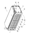
図1ないし図5に示すバッテリシステム100は、複数の電池セル1を積層している電池積層ブロック2と、この電池積層ブロック2の積層方向の両端部に配置している一対のエンドプレート3と、電池積層ブロック2の下に配置している弾性プレート9と、両端部を一対のエンドプレート3に連結して、電池積層ブロック2の電池セル1を積層方向に加圧状態で固定して、電池積層ブロック2の下に弾性プレート9を配置している結束具4とを備えている。
A
電池セル1は、図6に示すように、厚さに比べて幅が広い、対向するフラット面1Cを四角形とする角形電池で、厚さ方向に積層されて電池積層ブロック2としている。電池セル1は、電池ケース10を金属ケースとする非水系電解液電池である。非水系電解液電池である電池セル1は、リチウムイオン二次電池である。ただし、電池セルは、ニッケル水素電池やニッケルカドミウム電池等の他の全ての二次電池とすることもできる。図の電池セル1は、外形を四角形とする電池で、両面を対向するように積層して電池積層ブロック2としている。
As shown in FIG. 6, the
電池セル1は、対向するフラット面1Cの外形を四角形とする金属製の電池ケース10に、電極体(図示せず)を収納して電解液を充填している。金属ケースからなる電池ケース10は、アルミニウムやアルミニウム合金で製造することができる。電池ケース10は、底を閉塞する筒状に金属板をプレス加工している外装缶10Aと、この外装缶10Aの開口部を気密に閉塞している封口板10Bとを備えている。封口板10Bは平面状の金属板で、その外形を外装缶10Aの開口部の内形としている。封口板10Bは、外装缶10Aの開口部の内側に隙間なく挿入され、外装缶10Aの内面との間にレーザーを照射して外装缶10Aに溶接される。
In the
電池セル1は、封口板10Bの両端部に正負の電極端子13を固定して、封口板10Bを端子面1Aとして、端子面1Aの反対側の面、図6において電池セル1の下面を底面1Bとしている。さらに、封口板10Bは、正負の電極端子13の中間にはガス排出口12を設けている。ガス排出口12の内側には、所定の内圧で開弁する排出弁11を設けている。電池積層ブロック2は、複数の電池セル1を、端子面1Aを同一平面に位置する姿勢で積層している。
The
電池積層ブロック2は、隣接する電池セル1の正負の電極端子13に金属板のバスバー14を固定して、バスバー14で電池セル1を互いに直列に接続している。ただし、電池積層ブロックは、電池セルを直列及び/又は並列に接続することもできる。隣接する電池セルを互いに直列に接続するバッテリシステムは、出力電圧を高くして出力を大きくでき、隣接する電池セルを並列に接続して、充放電の電流を大きくできる。図6の電池積層ブロック2は、電池セル1の電極端子13に、直線状のバスバー14Aと、L字状のバスバー14Bを溶接して固定している。直線状のバスバー14AとL字状のバスバー14Bは、先端を互いに積層し、積層部に貫通孔14aを設けて、貫通孔14aに止ネジ15を挿通し、止ネジ15にナット16をねじ込んで、バスバー14を互いに固定している。
In the
図6に示す電池積層ブロック2は、複数の電池セル1の間に絶縁スペーサ5を挟んで積層している。図の電池積層ブロック2は、互いに隣接する電池セル1同士を逆向きに並べており、その両側において隣接する電極端子13同士をバスバー14で連結して、隣り合う2個の電池セル1を直列に接続して、すべての電池セル1を直列に接続している。ただ、本発明は、電池積層ブロックを構成する電池セルの個数とその接続状態を特定しない。
The
絶縁スペーサ5は、隣接する電池セル1の間に挟まれて電位差のある電池セル1を絶縁する。図に示す絶縁スペーサ5は、絶縁材のプラスチックを成形して製作される。絶縁スペーサ5は、隣接する電池セル1のフラット面1Cに接触するように配置されて、電池セル1の間に挟まれるプレート部20と、電池セル1の外周面の外側に配置される水平部22とをプラスチックで一体的に成形している。この絶縁スペーサ5は、水平部22の内側に電池セル1を配置して定位置に配置する形状として、電池セル1を位置ずれしないように積層できる。
The insulating
以上のように、絶縁スペーサ5で絶縁して積層される電池セル1は、外装缶10Aをアルミニウムなどの金属製にできる。ただ、電池積層ブロックは、必ずしも電池セルの間に絶縁スペーサを介在させる必要はない。例えば、電池セルの外装缶を絶縁材で成形し、あるいは電池セルの外装缶の外周を絶縁シートや絶縁塗料等で被覆する等の方法で、互いに隣接する電池セル同士を絶縁することによって、絶縁スペーサを不要とできるからである。
As described above, in the
さらに、図6に示す絶縁スペーサ5は、電池セル1を効果的に冷却するために、電池セル1との間に挟着されるプレート部20に、空気などの冷却気体を通過させる冷却隙間26を設けている。図6に示す絶縁スペーサ5のプレート部20は、電池セル1との対向面に、両側縁まで延びる溝25を設けて、電池セル1との間に冷却隙間26を設けている。図の絶縁スペーサ5は、複数の溝25を、互いに平行に所定の間隔で設けている。図のプレート部20は、両面に溝25を設けており、互いに隣接する電池セル1と絶縁スペーサ5との間に冷却隙間26を設けている。この構造は、プレート部20の両側に形成される冷却隙間26で、両側の電池セル1を効果的に冷却できる特長がある。ただ、絶縁スペーサは、片面にのみ溝を設けて、電池セルと絶縁スペーサとの間に冷却隙間を設けることもできる。図の冷却隙間26は、電池積層ブロック2の左右に開口するように水平方向に設けている。冷却隙間26に強制送風される空気は、電池セル1の外装缶10Aを直接に効率よく冷却する。この構造は、電池セル1の熱暴走を有効に阻止しながら、電池セル1を効率よく冷却できる特徴がある。
Further, the insulating
以上の絶縁スペーサ5は、電池セル1との間に冷却隙間26を設けて、この冷却隙間26に冷却用の空気などの冷却気体を強制的に送風して、電池セル1を冷却できる。ただ、絶縁スペーサは、必ずしも電池セルとの間に冷却隙間を設ける必要はなく、図7に示すように、電池積層ブロック2の底面に積層される弾性プレート9を冷却プレート30に熱結合状態に連結する構造とすることもできる。このバッテリシステム200は、冷却プレート30を冷却し、冷却プレート30で弾性プレート9を冷却して、弾性プレート9を介して電池セル1を冷却することができる。冷却プレート30は、表面に放熱フィン(図示せず)を設けて冷却し、あるいは、内部に冷却用の冷媒や冷却液を循環させて強制的に冷却できる。
The insulating
図6の絶縁スペーサ5は、電池セル1の端子面1A及び底面1Bの外側に水平部22を配置している。端子面1Aの外側、図において上に配置される第1の水平部22Aは、結束具4の嵌合部4Aと電池セル1の端子面1Aとの間に挟まれて、上面を嵌合部4Aに、下面を端子面1Aに密着させている。結束具4の嵌合部4Aは、第1の水平部22Aを介して端子面1Aを押圧して、各々の電池セル1の端子面1Aを嵌合部4Aでもって同一平面に配置する。電池セル1の底面1Bの外側、図において底面1Bの下に配置される第2の水平部22Bは、電池セル1の底面1Bと弾性押圧部19である弾性アーム19Aとの間にあって、上面を電池セル1の底面1Bに密着して、下面を弾性アーム19Aで押圧している。弾性アーム19Aは、第2の水平部22Bを介して電池セル1の底面1Bを押し上げて、各々の電池セル1の端子面1Aを嵌合部4Aでもって同一平面に配置している。
In the insulating
弾性プレート9は、電池セル1の底面1Bに配置されて、各々の電池セル1を底面1Bから端子面1Aに向かって弾性的に押圧する弾性押圧部19を有する。図5と図8の弾性プレート9は弾性変形できるステンレス等の金属板を裁断し、また、プレス加工して、複数の弾性アーム19Aを弾性押圧部19として一体構造に設けている。さらに、図5と図8の弾性プレート9は、電池セル1の底面1Bの長手方向に延びる一対の弾性アーム19Aを設けている。一対の弾性アーム19Aは弾性プレート9の両側部で弾性プレート9に連結されて、弾性プレート9の両側部から中央部に向かって延びるように設けている。図の弾性プレート9は、電池積層ブロック2の底面の外形に沿う矩形状の外周枠部9Aを備えており、この外周枠部9Aの両側部から内側に延びる複数の弾性アーム19Aを一体的に設けている。弾性アーム19Aは、先端に向かって、電池セル1の底面1Bに向かって突出する形状に折曲加工されている。弾性プレート9の両側部に設けている一対の弾性アーム19Aは、ひとつの電池セル1の底面1Bを押圧する。したがって、隣接する弾性アーム19Aの間隔は、積層している電池セル1の間隔に等しくして、弾性プレート9の両側部に複数の弾性アーム19Aを設けている。
The
さらに、図3と図8に示す弾性プレート9は、外周枠部9Aの両側縁に沿って補強リブ9Bを設けている。図の弾性プレート9は、外周枠部9Aの両側縁部を上方に向かって折曲して補強リブ9Bを設けている。この弾性プレート9は、両側縁に設けた補強リブ9Bによって、外周枠部9Aの両側部の剛性を高めることができる。この構造の弾性プレート9は、バッテリシステムの組み立て工程において、両側部を押圧して弾性押圧部19を弾性変形させる状態で、外周枠部9Aの両側部を変形させることなく押圧できる特徴がある。さらに、図の弾性プレート9は、外周枠部9Aの両側縁に設けた補強リブ9Bの内面が電池積層ブロック2の下側コーナー部の外側面に当接する構造としている。この弾性プレート9は、電池積層ブロック2の底面に対して、両側の補強リブ9Bで左右方向の位置を位置決めしながら定位置に配置できる特徴がある。
Further, the
エンドプレート3は、結束具4に連結されて、電池積層ブロック2を両端面から加圧して、電池セル1を積層方向に加圧する。エンドプレート3は、結束具4に固定されて、電池積層ブロック2の各電池セル1を所定の締め付け圧で加圧状態に固定する。エンドプレート3の外形は、電池セル1の外形にほぼ等しく、あるいはこれよりもわずかに大きく、四隅部に結束具4を連結して、電池積層ブロック2を加圧状態に固定して変形しない四角形の板状である。このエンドプレート3は、四隅部に結束具4を連結して、電池セル1の表面に面接触状態に密着し、電池セル1を均一な圧力で加圧状態に固定する。バッテリシステムは、電池積層ブロック2の両端部にエンドプレート3を配置し、両端のエンドプレート3をプレス機(図示せず)で加圧して、電池セル1を積層方向に加圧する状態に保持し、この状態でエンドプレート3に結束具4を固定して、電池積層ブロック2を所定の締め付け圧に保持して固定する。エンドプレート3が結束具4に連結された後、プレス機の加圧状態は解除される。
The
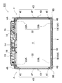
結束具4は、図1、図2、図4、及び図5に示すように、電池積層ブロック2の両端のエンドプレート3を連結して、複数の電池セル1を積層方向に加圧状態で固定する。結束具4は金属板をプレス加工して製作される。この結束具4は、図9に示すように、電池積層ブロック2の側面に配置される側面プレート4Xと、この側面プレート4Xの両端部にあって、エンドプレート3の外側面に配置されるL字状固定部4Cとを備え、L字状固定部4Cは、止ネジ18を介してエンドプレート3の外側端面に固定される。
1, 2, 4, and 5, the
さらに、結束具4は、電池セル1の端子面1Aの外側に配置される嵌合部4Aと、弾性プレート9の外側に配置される係止部4Bとを有する。底面1Bに弾性プレート9を積層する電池積層ブロック2は、嵌合部4Aと係止部4Bの間に配置される。図3と図9の結束具4は、側面プレート4Xの上縁を内側に直角に折曲して嵌合部4Aを設け、下縁を内側に直角に折曲して係止部4Bを設けている。さらに、側面プレート4Xは、外周縁部を除く内部に切除部4Dを設けて軽量化している。図9の側面プレート4Xは、外周縁部にある四角形の枠フレーム4Eを連結バー4Fで縦横に連結して、枠フレーム4Eを補強している。
Furthermore, the
嵌合部4Aは、内面を平面状として、各々の電池セル1の端子面1Aを同一平面に配置する。図3のバッテリシステム100は、電池セル1の端子面1Aに絶縁スペーサ5の水平部22を配置する。したがって、このバッテリシステム100は、端子面1Aと嵌合部4Aとの間に絶縁スペーサ5の水平部22が挟まれるように配置される。電池セル1の端子面1Aは、水平部22を介して嵌合部4Aに押し付けられて同一平面に配置される。本発明のバッテリシステムは、電池セルの端子面に必ずしも絶縁スペーサの水平部を配置しない。このバッテリシステムは、端子面を嵌合部の内面に接するように配置して、各々の電池セルの端子面を同一平面に配置する。このバッテリシステムは、嵌合部や端子面を絶縁材とし、あるいは嵌合部と端子面との間に積層シートや絶縁層を設ける。
4 A of fitting parts make the inner surface planar, and arrange | position the
係止部4Bは弾性プレート9の外側、図3において弾性プレート9の下にあって、弾性プレート9を押し上げて、弾性プレート9の弾性押圧部19を押し潰すように弾性変形させる状態に保持する。係止部4Bで電池積層ブロック2の底面に押し付けられている弾性プレート9は、弾性変形する弾性押圧部19の復元力で、電池セル1を押圧して、電池セル1の端子面1Aを同一平面に配置する。図3のバッテリシステム100は、弾性プレート9と電池セル1の底面1Bとの間に絶縁スペーサ5の水平部22を配置する。したがって、弾性押圧部19は水平部22を介して電池セル1を押し上げて、端子面1Aを同一平面に配置する。
The locking
嵌合部4Aと係止部4Bの内側間隔は、底面1Bに弾性プレート9を配置する電池積層ブロック2を配置して、弾性プレート9の弾性押圧部19を押し潰して弾性変形させる寸法とする。嵌合部4A及び係止部4Bと電池セル1との間に、絶縁スペーサ5の水平部22を配置するバッテリシステムは、嵌合部4Aと係止部4Bの内側間隔を、上下に絶縁スペーサ5の水平部22を積層して底面1Bに弾性プレート9を配置する電池積層ブロック2を配置して、弾性プレート9の弾性押圧部19を押し潰して弾性変形させる寸法とする。
The inner distance between the
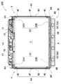
さらに、結束具4は、図9に示すように、弾性プレート9と電池積層ブロック2を嵌合部4Aと係止部4Bの間に挿通するとき、弾性押圧部19を押し潰し状態に保持するジグを案内するための切り欠き4aを、嵌合部4Aと係止部4Bの両方に設けている。図の結束具4は、嵌合部4Aと係止部4Bの両方に切り欠き4aを設けているが、本発明は、必ずしも嵌合部と係止部の両方に切り欠きを設ける必要はなく、嵌合部と係止部の一方に切り欠きを設けることもできる。それは、ジグで電池積層ブロックを押圧し、あるいは弾性プレートを押圧して弾性押圧部を押し潰す状態に保持して、このジグに切り欠きを案内しながら弾性プレートを積層している電池積層ブロックを嵌合部と係止部の間に挿通できるからである。
Further, as shown in FIG. 9, the
さらに、図4、図5、及び図9の結束具4は、切り欠き4aを、嵌合部4Aと係止部4Bの両端部に設けている。嵌合部4Aの切り欠き4aには、絶縁スペーサ5の第1の水平部22Aを介して電池積層ブロック2を押圧して弾性プレート9の弾性押圧部19を押し潰すジグが案内される。係止部4Bの切り欠き4aには、弾性プレート9を押圧して弾性押圧部19を押し潰すジグが案内される。ジグで押し潰された弾性押圧部19は、絶縁スペーサ5の第2の水平部22Bを介して電池積層ブロック2を押圧する。
Furthermore, the
以上の結束具4は、電池積層ブロック2の両端に積層しているエンドスペーサ5’に位置して切り欠き4aを設けている。このエンドスペーサ5’は、電池積層ブロック2の両端部に積層している最端積層電池セル1’とエンドプレート3との間に積層されている。両端部に切り欠き4aを設けている結束具4は、固定部4Cをエンドプレート3の外側に固定する状態で、両端部の切り欠き4aでもって、側面プレート4Xのコーナー部に集中する応力を分散して、側面プレート4Xの損傷を防止できる。図9の結束具4は、嵌合部4Aと係止部4Bの両端部の両方に切り欠き4aを設けているので、側面プレート4Xの上下のコーナー部に集中する応力を分散して、側面プレート4Xの四隅の損傷を防止できる特徴がある。
The above-described
さらに、図9の結束具4は、L字状固定部4Cと、嵌合部4A及び係止部4Bとの間に切り離し隙間4bを設けている。この形状の結束具4は、金属板をプレス加工して結束具4を安価に多量生産でき、さらに、嵌合部4Aと係止部4Bに設けた切り欠き4aと、切り離し隙間4bの両方でもって、側面プレート4Xの四隅のコーナー部に作用する応力集中をより効果的に防止して分散して、この部分の損傷をさらに効果的に防止できる特徴がある。
Furthermore, the
以上のバッテリシステム100は、以下の工程で組み立てられる。
(1)水平姿勢に配置する弾性プレート9の上に、電池セル1と絶縁スペーサ5とを交互に積層して電池積層ブロック2とする。
The
(1) The
(2)電池積層ブロック2の両端にエンドプレート3を配置して、電池積層ブロック2を積層方向に加圧する。このとき、弾性プレート9の弾性押圧部19で各々の電池セル1を押し上げて、電池セル1の端子面1Aを同一平面に配置する。このことを実現するために、電池セル1の端子面1Aの上に配置している絶縁スペーサ5の第1の水平部22Aを同一平面に配置する。第1の水平部22Aは、その上に水平ロッドや水平バーを配置して、これに押し付けて同一平面に配置することができる。
(2)
(3)図10に示すように、電池積層ブロック2の底に積層している弾性プレート9を、結束具4の係止部4Bに係止する状態で、嵌合部4Aの両端に設けている切り欠き4aが案内される位置において、ジグで電池積層ブロック2を押圧して(図において矢印Aで表示)、電池積層ブロック2を押し下げ、弾性プレート9の弾性押圧部19である弾性アーム19Aを押し潰す状態に保持する。この状態で、電池積層ブロック2を嵌合部4Aの内側に挿入する。電池積層ブロック2が嵌合部4Aの内側に挿入される状態で、電池積層ブロック2を押圧しているジグは切り欠き4aに案内される。したがって、ジグで電池積層ブロック2を押圧しながら、電池積層ブロック2と弾性プレート9を嵌合部4Aと係止部4Bの内側に挿入できる。
(3) As shown in FIG. 10, the
以上の方法は、嵌合部4Aの切り欠き4aが案内される位置において、ジグで電池積層ブロック2を押圧するが、以下の方法で、係止部4Bの切り欠き4aが案内される位置において、ジグで弾性プレート9を押圧することもできる。この方法は、図11に示すように、底に弾性プレート9を積層している電池積層ブロック2の上面に水平台35を当接させる状態で、係止部4Bの両端に設けている切り欠き4aが案内される位置において、ジグで弾性プレート9を押圧して(図において矢印Bで表示)、弾性プレート9を押し上げて、弾性プレート9の弾性押圧部19である弾性アーム19Aを押し潰す状態に保持する。この状態で、電池積層ブロック2に積層している弾性プレート9を電池積層ブロック2と共に結束具4の嵌合部4Aと係止部4Bの内側に挿入する。電池積層ブロック2と弾性プレート9を嵌合部4Aと係止部4Bの内側に挿入する状態で、弾性プレート9を押圧しているジグは係止部4Bの切り欠き4aに案内される。したがって、ジグで弾性プレート9を押圧しながら、電池積層ブロック2と弾性プレート9を嵌合部4Aと係止部4Bの内側に挿入できる。
In the above method, the
(4)結束具4の嵌合部4Aと係止部4Bとの間に、電池積層ブロック2と弾性プレート9とを積層状態で挿入し、この状態で結束具4のL字状固定部4Cをエンドプレート3の外側に固定する。その後、ジグが電池積層ブロック2や弾性プレート9を押圧する状態を解除する。
(4) The
以上の方法は、弾性プレート9の上に電池積層ブロック2を載せて組み立てるが、以上の方法とは上下反転して、電池積層ブロック2の上に弾性プレート9を載せて組み立てることもできる。この方法は、以下のようにしてバッテリシステムを組み立てる。
In the above method, the
(1)図12に示すように、水平姿勢に配置する水平台35の上に電池セル1の端子面1Aを載せて、電池セル1と絶縁スペーサ5とを交互に積層して電池積層ブロック2とし、その後、電池積層ブロック2の上に弾性プレート9を載せる。
(1) As shown in FIG. 12, the
(2)電池積層ブロック2の両端にエンドプレート3を配置して、電池積層ブロック2を積層方向に加圧する。
(2)
(3)結束具4の係止部4Bの両端に設けている切り欠き4aが案内される位置において、ジグで弾性プレート9を押圧し(図において矢印Bで表示)、弾性プレート9を電池積層ブロック2に押し付けて、弾性プレート9の弾性押圧部19である弾性アーム19Aを押し潰す状態に保持する。この状態で、電池積層ブロック2に積層している弾性プレート9を電池積層ブロック2と共に結束具4の嵌合部4Aと係止部4Bの内側に挿入する。電池積層ブロック2と弾性プレート9を嵌合部4Aと係止部4Bの内側に挿入する状態で、弾性プレート9を押圧しているジグは係止部4Bの切り欠き4aに案内される。したがって、ジグで弾性プレート9を押圧しながら、電池積層ブロック2と弾性プレート9を嵌合部4Aと係止部4Bの内側に挿入できる。
(3) The
以上の方法は、係止部4Bの切り欠き4aが案内される位置において、ジグで弾性プレート9を押圧するが、以下の方法で嵌合部の切り欠きが案内される位置をジグで押圧することもできる。この方法は、図示しないが、電池積層ブロックの上に積層している弾性プレートを結束具の係止部に係止する状態で、嵌合部の両端に設けている切り欠きが案内される位置において、ジグで電池積層ブロックを押圧して、電池積層ブロックを押し上げて、弾性プレートの弾性押圧部である弾性アームを押し潰す状態に保持する。この状態で、上に弾性プレートを積層している電池積層ブロックを嵌合部の内側に挿入する。電池積層ブロックを嵌合部の内側に挿入する状態で、電池積層ブロックを押圧しているジグは嵌合部の切り欠きに案内される。したがって、ジグで電池積層ブロックを押圧しながら、電池積層ブロックと弾性プレートを嵌合部と係止部の内側に挿入できる。
In the above method, the
(4)結束具4の嵌合部4Aと係止部4Bとの間に、電池積層ブロック2と弾性プレート9とを積層状態で挿入し、この状態で、結束具4のL字状固定部4Cをエンドプレート3の外側に固定する。その後、ジグが電池積層ブロック2や弾性プレート9を押圧する状態を解除する。
(4) The
以上のバッテリシステムは、電動車両を走行させるモータに電力を供給する電源装置に最適である。バッテリシステムを搭載する電動車両としては、エンジンとモータの両方で走行するハイブリッド自動車やプラグインハイブリッド自動車、あるいはモータのみで走行する電気自動車等の電動車両が利用でき、これらの電動車両の電源として使用される。ただ、本発明はバッテリシステムの用途を電動車両に搭載する電源装置には特定せず、たとえば、太陽光発電、風力発電などの自然エネルギーを蓄電する電源装置として使用でき、また深夜電力を蓄電する電源装置等の電源装置のように、大電力を蓄電する全ての用途に最適である。 The battery system described above is most suitable for a power supply device that supplies electric power to a motor that drives an electric vehicle. As an electric vehicle equipped with a battery system, an electric vehicle such as a hybrid vehicle or a plug-in hybrid vehicle that runs with both an engine and a motor, or an electric vehicle that runs only with a motor can be used, and used as a power source for these electric vehicles. Is done. However, the present invention does not specify the use of the battery system as a power supply device mounted on an electric vehicle, and can be used, for example, as a power supply device that stores natural energy such as solar power generation or wind power generation, and stores midnight power. Like power supply devices such as power supply devices, it is optimal for all applications that store large amounts of power.
本発明のバッテリシステムは、大電力が要求される車両のモータに電力を供給する電源装置や、自然エネルギーや深夜電力を蓄電する蓄電装置に最適に使用される。 The battery system of the present invention is optimally used for a power supply device that supplies electric power to a motor of a vehicle that requires a large amount of power, or a power storage device that stores natural energy or midnight power.
100、200…バッテリシステム
1…電池セル
1’…最端積層電池セル
1A…端子面
1B…底面
1C…フラット面
2…電池積層ブロック
3…エンドプレート
4…結束具
4X…側面プレート
4A…嵌合部
4B…係止部
4C…L字状固定部
4D…切除部
4E…枠フレーム
4F…連結バー
4a…切り欠き
4b…切り離し隙間
5…絶縁スペーサ
5’…エンドスペーサ
9…弾性プレート
9A…外周枠部
9B…補強リブ
10…電池ケース
10A…外装缶
10B…封口板
11…排出弁
12…ガス排出口
13…電極端子
14…バスバー
14A…直線状のバスバー
14B…L字状のバスバー
14a…貫通孔
15…止ネジ
16…ナット
18…止ネジ
19…弾性押圧部
19A…弾性アーム
20…プレート部
22…水平部
22A…第1の水平部
22B…第2の水平部
25…溝
26…冷却隙間
30…冷却プレート
35…水平台
901…電池セル
901A…端子面
902…電池積層ブロック
904…結束具
904A…嵌合部
904B…係止部
905…絶縁スペーサ
909…弾性プレート
919…弾性押圧部
DESCRIPTION OF
Claims (4)
前記電池セルの端子面の反対側に位置する底面に配置されて、各々の電池セルを底面から前記端子面に向かって弾性的に押圧する弾性押圧部を有する弾性プレートと、
前記電池積層ブロックの両端部にあって、前記電池セルを積層方向に加圧して固定する一対のエンドプレートと、
一対のエンドプレートを連結して、複数の電池セルを積層方向に加圧状態で固定する結束具とを備えるバッテリシステムであって、
前記結束具は、前記電池積層ブロックの端子面の外側に配置してなる嵌合部と、前記弾性プレートの外側に配置してなる係止部とを有し、
前記電池積層ブロックと前記弾性プレートが、前記結束具の嵌合部と係止部との間に配置され、前記弾性押圧部が弾性変形されて、各々の弾性押圧部の弾性復元力で各々の電池セルを前記嵌合部に向かって弾性的に押圧しており、
さらに、前記嵌合部と前記係止部の何れか一方又は両方に、前記電池積層ブロック又は前記弾性プレートを押圧するジグを案内する切り欠きを設けてなることを特徴とするバッテリシステム。 A plurality of battery cells provided with positive and negative electrode terminals on the terminal surface are stacked in the thickness direction, and each battery cell is electrically connected through a bus bar fixed to the electrode terminal of each battery cell. A battery stack block;
An elastic plate that is disposed on the bottom surface located on the opposite side of the terminal surface of the battery cell and has an elastic pressing portion that elastically presses each battery cell from the bottom surface toward the terminal surface;
A pair of end plates at both ends of the battery stack, for pressing and fixing the battery cells in the stacking direction;
A battery system comprising a binding tool that connects a pair of end plates and fixes a plurality of battery cells in a stacked state in a pressurized state,
The binding tool has a fitting portion arranged outside the terminal surface of the battery stack, and a locking portion arranged outside the elastic plate,
The battery stack block and the elastic plate are disposed between the fitting part and the locking part of the binding tool, and the elastic pressing part is elastically deformed, and each elastic pressing part is elastically restored by an elastic restoring force. The battery cell is elastically pressed toward the fitting portion,
The battery system further comprises a notch for guiding a jig for pressing the battery stack or the elastic plate in one or both of the fitting portion and the locking portion.
前記切り欠きが結束具の両端部に設けられてなることを特徴とするバッテリシステム。 The battery system according to claim 1,
A battery system, wherein the notches are provided at both ends of a binding tool.
前記結束具が、前記電池積層ブロックの側面に配置してなる側面プレートと、この側面プレートの両端部に連結されて前記エンドプレートの外側端面に配置されるL字状固定部とを備え、
前記嵌合部と前記係止部が前記側面プレートの両側縁に設けられて、前記嵌合部と前記係止部の両端部に切り欠きを設けてなることを特徴とするバッテリシステム。 The battery system according to claim 1 or 2,
The binding device includes a side plate arranged on a side surface of the battery stack, and an L-shaped fixing portion connected to both end portions of the side plate and arranged on an outer end surface of the end plate,
The battery system, wherein the fitting portion and the locking portion are provided on both side edges of the side plate, and notches are provided at both ends of the fitting portion and the locking portion.
前記電池積層ブロックの底面に配置されて、各々の電池セルを底面から前記端子面に向かって弾性的に押圧する弾性押圧部を有する弾性プレートと、
前記電池積層ブロックの両端部にあって、前記電池セルを積層方向に加圧して固定する一対のエンドプレートと、
一対のエンドプレートを連結して、複数の電池セルを積層方向に加圧状態で固定する結束具とを備え、
前記結束具は、前記電池積層ブロックの端子面の外側に配置してなる嵌合部と、前記弾性プレートの外側に配置してなる係止部とを有し、
前記電池積層ブロックと前記弾性プレートが、前記結束具の嵌合部と係止部との間に配置され、前記弾性押圧部が弾性変形されて、各々の弾性押圧部の弾性復元力で各々の電池セルを前記嵌合部に向かって弾性的に押圧してなるバッテリシステムの製造方法であって、
前記結束具の前記嵌合部と前記係止部の何れか一方又は両方に、前記電池積層ブロック又は前記弾性プレートを押圧するジグを案内する切り欠きを設けると共に、
前記電池積層ブロックの底面に前記弾性プレートを配置すると共に、電池積層ブロックの両端にエンドプレートを配置して、前記エンドプレートでもって各々の電池セルを積層方向に加圧する状態で、前記切り欠きに案内されるジグでもって、前記弾性プレートの弾性押圧部を弾性変形させる状態に保持して、前記結束具の嵌合部と係止部との間に前記電池積層ブロックと前記弾性プレートとを配置して、前記ジグを前記切り欠きに案内し、この状態で前記結束具を前記エンドプレートに固定することを特徴とするバッテリシステムの製造方法。 A plurality of battery cells provided with positive and negative electrode terminals on the terminal surface are stacked in the thickness direction, and each battery cell is electrically connected through a bus bar fixed to the electrode terminal of each battery cell. A battery stack block;
An elastic plate that is disposed on the bottom surface of the battery stack and has an elastic pressing portion that elastically presses each battery cell from the bottom surface toward the terminal surface;
A pair of end plates at both ends of the battery stack, for pressing and fixing the battery cells in the stacking direction;
A pair of end plates connected to each other, and a binding tool for fixing a plurality of battery cells in a pressurized state in the stacking direction,
The binding tool has a fitting portion arranged outside the terminal surface of the battery stack, and a locking portion arranged outside the elastic plate,
The battery stack block and the elastic plate are disposed between the fitting part and the locking part of the binding tool, and the elastic pressing part is elastically deformed, and each elastic pressing part is elastically restored by an elastic restoring force. A battery system manufacturing method in which a battery cell is elastically pressed toward the fitting portion,
While providing either one or both of the fitting part and the locking part of the binding tool with a notch for guiding a jig for pressing the battery stack block or the elastic plate,
The elastic plate is disposed on the bottom surface of the battery stack, and end plates are disposed at both ends of the battery stack, and each battery cell is pressed in the stacking direction with the end plate. With the guided jig, the elastic pressing portion of the elastic plate is held in an elastically deformed state, and the battery stack block and the elastic plate are arranged between the fitting portion and the locking portion of the binding tool. And the said jig is guided to the said notch, The said binding tool is fixed to the said end plate in this state, The manufacturing method of the battery system characterized by the above-mentioned.
Priority Applications (1)
| Application Number | Priority Date | Filing Date | Title |
|---|---|---|---|
| JP2014061506A JP6231918B2 (en) | 2014-03-25 | 2014-03-25 | Battery system and manufacturing method thereof |
Applications Claiming Priority (1)
| Application Number | Priority Date | Filing Date | Title |
|---|---|---|---|
| JP2014061506A JP6231918B2 (en) | 2014-03-25 | 2014-03-25 | Battery system and manufacturing method thereof |
Publications (2)
| Publication Number | Publication Date |
|---|---|
| JP2015185413A JP2015185413A (en) | 2015-10-22 |
| JP6231918B2 true JP6231918B2 (en) | 2017-11-15 |
Family
ID=54351713
Family Applications (1)
| Application Number | Title | Priority Date | Filing Date |
|---|---|---|---|
| JP2014061506A Active JP6231918B2 (en) | 2014-03-25 | 2014-03-25 | Battery system and manufacturing method thereof |
Country Status (1)
| Country | Link |
|---|---|
| JP (1) | JP6231918B2 (en) |
Families Citing this family (9)
| Publication number | Priority date | Publication date | Assignee | Title |
|---|---|---|---|---|
| FR3020722A1 (en) * | 2014-04-30 | 2015-11-06 | Valeo Systemes Thermiques | DEVICE FOR SUPPORTING A TUBE, IN PARTICULAR A TUBE OF A HEAT EXCHANGER INTENDED TO COME IN CONTACT WITH A BATTERY OF A MOTOR VEHICLE |
| JP6360259B2 (en) * | 2016-02-24 | 2018-07-18 | 日本碍子株式会社 | Battery device, battery unit and battery device installation method |
| JP6596467B2 (en) * | 2017-06-28 | 2019-10-23 | 本田技研工業株式会社 | Battery module |
| WO2019064722A1 (en) * | 2017-09-29 | 2019-04-04 | 三洋電機株式会社 | Power supply device |
| DE102018120394A1 (en) * | 2018-08-21 | 2020-02-27 | Kirchhoff Automotive Deutschland Gmbh | battery case |
| CN109822239A (en) * | 2019-03-14 | 2019-05-31 | 广东顺德华焯机械科技有限公司 | A kind of new energy battery case synchronous welding component |
| JP7149233B2 (en) * | 2019-07-18 | 2022-10-06 | 本田技研工業株式会社 | Cell fixing parts and battery packs |
| JP7149232B2 (en) * | 2019-07-18 | 2022-10-06 | 本田技研工業株式会社 | battery pack |
| WO2023283873A1 (en) * | 2021-07-15 | 2023-01-19 | 宁德时代新能源科技股份有限公司 | Battery and power consuming device |
Family Cites Families (7)
| Publication number | Priority date | Publication date | Assignee | Title |
|---|---|---|---|---|
| US8999557B2 (en) * | 2010-04-21 | 2015-04-07 | Samsung Sdi Co., Ltd. | Battery pack with elastic frame |
| JP2012256465A (en) * | 2011-06-08 | 2012-12-27 | Honda Motor Co Ltd | Battery module |
| JP2013051048A (en) * | 2011-08-30 | 2013-03-14 | Sanyo Electric Co Ltd | Power supply device |
| JP5985255B2 (en) * | 2012-05-25 | 2016-09-06 | 三洋電機株式会社 | Power supply device, vehicle including this power supply device, and power storage device |
| JP2015082391A (en) * | 2013-10-22 | 2015-04-27 | 本田技研工業株式会社 | Electricity storage device |
| JP6070999B2 (en) * | 2013-11-18 | 2017-02-01 | 本田技研工業株式会社 | Power storage module |
| JP6279948B2 (en) * | 2014-03-25 | 2018-02-14 | 三洋電機株式会社 | Battery system manufacturing method and battery system manufactured by this method |
-
2014
- 2014-03-25 JP JP2014061506A patent/JP6231918B2/en active Active
Also Published As
| Publication number | Publication date |
|---|---|
| JP2015185413A (en) | 2015-10-22 |
Similar Documents
| Publication | Publication Date | Title |
|---|---|---|
| JP6231918B2 (en) | Battery system and manufacturing method thereof | |
| JP6279948B2 (en) | Battery system manufacturing method and battery system manufactured by this method | |
| JP6392323B2 (en) | Battery system | |
| JP5535794B2 (en) | Assembled battery | |
| EP3151307B1 (en) | Battery module and battery pack comprising same | |
| US9947958B2 (en) | Power source module | |
| US11462790B2 (en) | Power supply device | |
| KR102315847B1 (en) | Battery Pack Comprising Battery Pack Frame Capable of Preventing Welding Defect and Pressing Jig for Preparing the Same | |
| JP6414952B2 (en) | Battery pack | |
| JP4974578B2 (en) | Pack battery | |
| JP4757508B2 (en) | Electrical device assembly | |
| JP4868889B2 (en) | Assembled battery | |
| JP6184959B2 (en) | Battery system, vehicle including battery system, and power storage device | |
| JP7303270B2 (en) | battery pack | |
| JP6382640B2 (en) | Battery system | |
| JP2009231126A (en) | Battery pack | |
| JP2015187911A (en) | Battery system for vehicle and electric vehicle with battery system | |
| JP6948626B2 (en) | Separator, battery module and battery module manufacturing method | |
| KR20170062845A (en) | Battery Module Comprising Unit Module Having Simple Structure | |
| JP6594307B2 (en) | Module having a plurality of removable cells, battery comprising the module, and vehicle comprising the battery | |
| JP6866405B2 (en) | Battery module, manufacturing method of battery module | |
| JP2018133152A (en) | Battery module and battery pack | |
| CN112514146B (en) | Power supply device, vehicle having the same, and buffer body | |
| JP2014192091A (en) | Power storage module | |
| JP6431982B2 (en) | Container for battery module and battery module having such container |
Legal Events
| Date | Code | Title | Description |
|---|---|---|---|
| A621 | Written request for application examination |
Free format text: JAPANESE INTERMEDIATE CODE: A621 Effective date: 20161117 |
|
| A977 | Report on retrieval |
Free format text: JAPANESE INTERMEDIATE CODE: A971007 Effective date: 20170913 |
|
| TRDD | Decision of grant or rejection written | ||
| A01 | Written decision to grant a patent or to grant a registration (utility model) |
Free format text: JAPANESE INTERMEDIATE CODE: A01 Effective date: 20171003 |
|
| A61 | First payment of annual fees (during grant procedure) |
Free format text: JAPANESE INTERMEDIATE CODE: A61 Effective date: 20171020 |
|
| R150 | Certificate of patent or registration of utility model |
Ref document number: 6231918 Country of ref document: JP Free format text: JAPANESE INTERMEDIATE CODE: R150 |
|
| R250 | Receipt of annual fees |
Free format text: JAPANESE INTERMEDIATE CODE: R250 |
|
| R250 | Receipt of annual fees |
Free format text: JAPANESE INTERMEDIATE CODE: R250 |
|
| R250 | Receipt of annual fees |
Free format text: JAPANESE INTERMEDIATE CODE: R250 |
|
| R250 | Receipt of annual fees |
Free format text: JAPANESE INTERMEDIATE CODE: R250 |