JP6231774B2 - Electronic device and control method thereof - Google Patents
Electronic device and control method thereof Download PDFInfo
- Publication number
- JP6231774B2 JP6231774B2 JP2013109388A JP2013109388A JP6231774B2 JP 6231774 B2 JP6231774 B2 JP 6231774B2 JP 2013109388 A JP2013109388 A JP 2013109388A JP 2013109388 A JP2013109388 A JP 2013109388A JP 6231774 B2 JP6231774 B2 JP 6231774B2
- Authority
- JP
- Japan
- Prior art keywords
- touch
- tactile sensation
- electronic device
- touch operation
- stimulus
- Prior art date
- Legal status (The legal status is an assumption and is not a legal conclusion. Google has not performed a legal analysis and makes no representation as to the accuracy of the status listed.)
- Active
Links
Images


Classifications
-
- G—PHYSICS
- G06—COMPUTING; CALCULATING OR COUNTING
- G06F—ELECTRIC DIGITAL DATA PROCESSING
- G06F3/00—Input arrangements for transferring data to be processed into a form capable of being handled by the computer; Output arrangements for transferring data from processing unit to output unit, e.g. interface arrangements
- G06F3/01—Input arrangements or combined input and output arrangements for interaction between user and computer
- G06F3/016—Input arrangements with force or tactile feedback as computer generated output to the user
-
- G—PHYSICS
- G06—COMPUTING; CALCULATING OR COUNTING
- G06F—ELECTRIC DIGITAL DATA PROCESSING
- G06F3/00—Input arrangements for transferring data to be processed into a form capable of being handled by the computer; Output arrangements for transferring data from processing unit to output unit, e.g. interface arrangements
- G06F3/01—Input arrangements or combined input and output arrangements for interaction between user and computer
- G06F3/03—Arrangements for converting the position or the displacement of a member into a coded form
- G06F3/041—Digitisers, e.g. for touch screens or touch pads, characterised by the transducing means
-
- G—PHYSICS
- G06—COMPUTING; CALCULATING OR COUNTING
- G06F—ELECTRIC DIGITAL DATA PROCESSING
- G06F3/00—Input arrangements for transferring data to be processed into a form capable of being handled by the computer; Output arrangements for transferring data from processing unit to output unit, e.g. interface arrangements
- G06F3/01—Input arrangements or combined input and output arrangements for interaction between user and computer
- G06F3/048—Interaction techniques based on graphical user interfaces [GUI]
- G06F3/0484—Interaction techniques based on graphical user interfaces [GUI] for the control of specific functions or operations, e.g. selecting or manipulating an object, an image or a displayed text element, setting a parameter value or selecting a range
- G06F3/0485—Scrolling or panning
-
- G—PHYSICS
- G06—COMPUTING; CALCULATING OR COUNTING
- G06F—ELECTRIC DIGITAL DATA PROCESSING
- G06F3/00—Input arrangements for transferring data to be processed into a form capable of being handled by the computer; Output arrangements for transferring data from processing unit to output unit, e.g. interface arrangements
- G06F3/01—Input arrangements or combined input and output arrangements for interaction between user and computer
- G06F3/048—Interaction techniques based on graphical user interfaces [GUI]
- G06F3/0487—Interaction techniques based on graphical user interfaces [GUI] using specific features provided by the input device, e.g. functions controlled by the rotation of a mouse with dual sensing arrangements, or of the nature of the input device, e.g. tap gestures based on pressure sensed by a digitiser
- G06F3/0488—Interaction techniques based on graphical user interfaces [GUI] using specific features provided by the input device, e.g. functions controlled by the rotation of a mouse with dual sensing arrangements, or of the nature of the input device, e.g. tap gestures based on pressure sensed by a digitiser using a touch-screen or digitiser, e.g. input of commands through traced gestures
- G06F3/04883—Interaction techniques based on graphical user interfaces [GUI] using specific features provided by the input device, e.g. functions controlled by the rotation of a mouse with dual sensing arrangements, or of the nature of the input device, e.g. tap gestures based on pressure sensed by a digitiser using a touch-screen or digitiser, e.g. input of commands through traced gestures for inputting data by handwriting, e.g. gesture or text
-
- G—PHYSICS
- G06—COMPUTING; CALCULATING OR COUNTING
- G06F—ELECTRIC DIGITAL DATA PROCESSING
- G06F2203/00—Indexing scheme relating to G06F3/00 - G06F3/048
- G06F2203/041—Indexing scheme relating to G06F3/041 - G06F3/045
- G06F2203/04104—Multi-touch detection in digitiser, i.e. details about the simultaneous detection of a plurality of touching locations, e.g. multiple fingers or pen and finger
-
- G—PHYSICS
- G06—COMPUTING; CALCULATING OR COUNTING
- G06F—ELECTRIC DIGITAL DATA PROCESSING
- G06F2203/00—Indexing scheme relating to G06F3/00 - G06F3/048
- G06F2203/048—Indexing scheme relating to G06F3/048
- G06F2203/04806—Zoom, i.e. interaction techniques or interactors for controlling the zooming operation
-
- G—PHYSICS
- G06—COMPUTING; CALCULATING OR COUNTING
- G06F—ELECTRIC DIGITAL DATA PROCESSING
- G06F2203/00—Indexing scheme relating to G06F3/00 - G06F3/048
- G06F2203/048—Indexing scheme relating to G06F3/048
- G06F2203/04808—Several contacts: gestures triggering a specific function, e.g. scrolling, zooming, right-click, when the user establishes several contacts with the surface simultaneously; e.g. using several fingers or a combination of fingers and pen
Description
本発明は電子機器およびその制御方法に関し、特には物理的なフィードバックを提供可能な入力デバイス等の電子機器およびその制御方法に関する。 The present invention relates to an electronic device and a control method thereof, and more particularly to an electronic device such as an input device capable of providing physical feedback and a control method thereof.
従来、グラフィカルユーザインタフェース(GUI)は主にキーボードやマウスと言った入力機器を用いて操作されてきた。一方、画面上に透明なタッチパネルを設けることで、ボタンアイコン等のGUIを画面上で直接操作可能とした装置も増えており、このような装置の代表例として例えばスマートフォンやタブレット端末を挙げることができる。 Conventionally, a graphical user interface (GUI) has been mainly operated using input devices such as a keyboard and a mouse. On the other hand, by providing a transparent touch panel on the screen, there are an increasing number of devices that can directly operate a GUI such as a button icon on the screen. Examples of such devices include smartphones and tablet terminals. it can.
特に近年では、ボタンの押下を擬似的に実現するだけでなく、入力座標の軌跡に応じた動作を提供することも行われている。これにより、例えばタッチパネルに対して指やスタイラスなどによって特定の記号やジェスチャーを入力することで、対応する特定の動作を実行させることができる。 In particular, in recent years, not only pseudo-pressing a button but also providing an operation according to the locus of input coordinates has been performed. Accordingly, for example, by inputting a specific symbol or gesture to the touch panel with a finger or a stylus, a corresponding specific operation can be executed.
また、複数の入力座標を同時に認識可能なタッチパネルを用いることで、より複雑なジェスチャー入力を受け付け可能な装置も増えている。しかしながら、様々な入力方法が可能になってくると、それを覚える必要がある。また、全ての入力方法が常に可能とは限らないため、操作に対して期待した結果が得られず、ユーザに不快な思いをさせる可能性がある。したがって、現在の画面で有効な入力方法をユーザが把握できることが望まれるが、いわゆるヘルプ画面のようなもので入力方法を一覧表示する方法では、ユーザの使い勝手がよくないため、より直感的な方法が望ましい。 In addition, by using a touch panel capable of simultaneously recognizing a plurality of input coordinates, an increasing number of devices can accept more complicated gesture inputs. However, when various input methods become possible, it is necessary to remember them. Moreover, since all the input methods are not always possible, the expected result for the operation cannot be obtained, which may make the user feel uncomfortable. Therefore, it is desirable for the user to be able to grasp the effective input method on the current screen, but the method of displaying a list of input methods such as a so-called help screen is not user-friendly, so it is a more intuitive method. Is desirable.
特許文献1では、タッチパネルで検出されているタッチ入力の軌跡に応じて、その時点で可能なジェスチャー操作の候補に関するガイダンス表示を行うことが提案されている。 Japanese Patent Application Laid-Open No. 2004-133830 proposes performing guidance display regarding candidates for gesture operations that are possible at that time in accordance with the locus of touch input detected on the touch panel.
しかしながら、特許文献1に記載されるように、タッチ入力が継続されている間、可能なジェスチャー操作の情報をリアルタイムに表示する場合、ジェスチャー操作の情報を表示するためのスペースが必要なため、表示レイアウトが制約される。例えば、ガイダンス表示を他の表示物の上に重畳表示すると、他の表示物が見づらくなってしまう。また、他の表示物を隠さないようにガイダンス表示用のスペースを設けると、他の表示物を表示するスペースが狭くなり、表示可能な項目数が少なくなったり表示サイズが小さくなったりする。 However, as described in Patent Document 1, when information on possible gesture operations is displayed in real time while touch input is continued, a space for displaying information on gesture operations is required. Layout is constrained. For example, when the guidance display is superimposed on another display object, it becomes difficult to see the other display object. If a guidance display space is provided so as not to hide other display objects, the space for displaying other display objects becomes narrow, and the number of displayable items decreases and the display size decreases.
また、ガイダンス表示を重畳表示する場合も専用のスペースを設ける場合も、ガイダンス表示がタッチ入力している指やスタイラスで隠されてしまうことが起こりうる。表示以外の方法、例えば音声ガイダンスなどを用いることも考えられるが、音声ガイダンスは周囲の迷惑になり得るほか、騒音の多い場所では聞きとりづらいなどの懸念がある。 In addition, when the guidance display is displayed in a superimposed manner or when a dedicated space is provided, the guidance display may be hidden by a finger or stylus that is touch-input. Although it is conceivable to use a method other than the display, such as voice guidance, the voice guidance may be a nuisance to the surroundings, and there are concerns that it is difficult to hear in a noisy place.
本発明はこのような従来技術の課題に鑑みてなされたもので、受付可能な操作方法を、表示や音声とは異なる方法でユーザに通知可能な電子機器およびその制御方法を提供することを目的とする。 The present invention has been made in view of the problems of the prior art, and an object of the present invention is to provide an electronic device capable of notifying a user of a receivable operation method by a method different from display or sound and a control method thereof. And
上記課題を解決するために、本発明の電子機器は、入力手段に対するタッチ操作を受付ける受付手段と、受付手段で受け付けたタッチ操作に応じた処理を行う処理手段と、入力手段にタッチしている部位を通じてタッチを行っているユーザが感知可能な刺激を発生させる触感発生手段と、受付手段で受付可能なタッチ操作のパターンに対応した刺激を生成するように触感発生手段を制御する制御手段と、を有する電子機器であって、制御手段は、受付手段が受付可能な複数の接触入力のパターンのうち、電子機器の動作の状態に応じた有効なパターンに対応した刺激を生成するように制御を行うことを特徴とする。 In order to solve the above problems, an electronic device according to the present invention touches an input unit, a receiving unit that receives a touch operation on an input unit, a processing unit that performs a process according to the touch operation received by the receiving unit, and the input unit. Tactile sensation generating means for generating a stimulus that can be sensed by a user who is touching through the site; and control means for controlling the tactile sensation generating means so as to generate a stimulus corresponding to a touch operation pattern that can be received by the receiving means ; The control means performs control so as to generate a stimulus corresponding to an effective pattern according to an operation state of the electronic equipment among a plurality of contact input patterns that can be received by the receiving means. It is characterized by performing .
本発明によれば、受付可能な操作方法を、表示や音声とは異なる方法でユーザに通知可能な電子機器およびその制御方法を提供することができる。 ADVANTAGE OF THE INVENTION According to this invention, the electronic device which can notify a user of the operation method which can be received by the method different from a display or an audio | voice, and its control method can be provided.
<第1の実施形態>
以下、図面を参照して、本発明をその例示的な実施形態に基づいて詳細に説明する。図1は、本発明の第1の実施形態に係る電子機器100の機能構成例を示すブロック図である。本発明を適用可能な電子機器100は、タッチパネルのような接触感知式の入力機器を備える任意の機器であってよいが、特には携帯電話機、携帯ゲーム機、タブレット端末のような、表示装置上にタッチパネルが配置される電子機器に好適に適用できる。また、携帯型機器に限らず、複写機やプリンタ、家電製品などにも適用可能である。図1では、本発明を適用可能な電子機器が一般的に備えると考えられる機能構成例を示している。
<First Embodiment>
Hereinafter, the present invention will be described in detail based on exemplary embodiments with reference to the drawings. FIG. 1 is a block diagram illustrating a functional configuration example of an
CPU101、メモリ102、不揮発性メモリ103、画像処理部104、ディスプレイ105、操作部106、記録媒体I/F107、外部I/F109、通信I/F110、システムタイマー112、触感発生部113が、内部バス150に接続されている。これらの、内部バス150に接続される各部は、内部バス150を介して互いにデータを送受信可能である。
メモリ102は、例えばRAM(半導体素子を利用した揮発性のメモリなど)からなる。CPU101は、例えば不揮発性メモリ103に格納されるプログラムに従い、メモリ102をワークメモリとして用いて、電子機器100の各部を制御することにより、後述する電子機器100の動作を実現する。不揮発性メモリ103には、画像データや音声データ、その他のデータ、CPU101が実行する各種プログラムなどが格納される。不揮発性メモリ103は例えばハードディスクドライブ(HDD)、ソリッドステートドライブ(SSD)、ROM(EEPROM等の書き換え可能なものを含む)などで構成することができる。
The
画像処理部104は、CPU101の制御に基づいて、不揮発性メモリ103や記録媒体108に格納された画像データや、外部I/F109を介して取得した映像信号、通信I/F110を介して取得した画像データなどに対して各種画像処理を施す。画像処理部104が行う画像処理には、A/D変換処理、D/A変換処理、画像データの符号化処理、圧縮処理、デコード処理、拡大/縮小処理(リサイズ)、ノイズ低減処理、色変換処理などが含まれる。画像処理部104は特定の画像処理を施すための専用の回路ブロックで構成しても良い。また、画像処理の少なくとも一部は画像処理部104を用いずにCPU101が画像処理プログラムを実行することで実現してもよい。
Based on the control of the
ディスプレイ105は、CPU101の制御に基づいて、例えば記録媒体108に記録された画像や文章などのほか、アプリケーションプログラムやOSが用いるGUI(Graphical User Interface)画像などを表示する。CPU101はディスプレイ105に表示するための映像信号をプログラムに従って生成し、映像信号をディスプレイ105に出力するように電子機器100の各部を制御する。ディスプレイ105は出力された映像信号に基づいて映像を表示する。なお、ディスプレイ105は外部装置として、電子機器100はディスプレイ105に表示させるための映像信号を出力する構成としてもよい。
Under the control of the
操作部106は、キーボードなどの文字情報入力デバイスや、マウスやタッチパネル106aといったポインティングデバイス、ボタン、ダイヤル、ジョイスティック、タッチセンサ、タッチパッドなどを含む、ユーザ操作を受け付けるための入力デバイスである。また、入力デバイスの、タッチ操作を検知可能な面をタッチ面ともよぶ。なお、本実施形態ではタッチパネル106aは透明もしくは半透明であり、ディスプレイ105の表示画面上に表示画面が視認できるように配置されるが、不透明でディスプレイ105とは別の位置に配置されてもよい。また、タッチパネル106aは、接触入力の座標情報を出力し、タッチパネル106aの出力する座標情報と、ディスプレイ105の表示座標との関係は既知であるものとする。タッチパネル106aは複数の異なる位置に対して同時に入力がなされた場合、個々の入力に対する座標情報を出力可能なタイプであっても、1つの入力に対する座標情報のみを出力するタイプであってもよい。
The
タッチパネル106aには、抵抗膜方式、静電容量方式、表面弾性波方式、赤外線方式、電磁誘導方式、画像認識方式、光センサ方式等、公知の様々な方式のタッチパネルのうち、任意のものを用いることができる。
As the
記録媒体I/F107は、CPU101の制御に基づき、メモリーカードやCD、DVDといった着脱可能な記録媒体108に対するデータの読み出しおよび書き込みを行う。外部I/F109は、有線または無線によって接続された外部機器と映像信号や音声信号の入出力を行うためのインターフェースである。通信I/F110は、外部機器やインターネット111などと通信して、ファイルやコマンドなどの各種データの送受信を行うためのインターフェースである。
システムタイマー112は、各種制御に用いる時間や、内蔵時計の時間を計測する。
The recording medium I /
The
本実施形態において、CPU101はタッチパネル106aへの以下の操作/状態を検出できる。
・タッチパネル106aに物体が接触したこと(以下、タッチダウンと称する)。
・タッチパネル106aに物体が接触した状態にあること(以下、タッチオンと称する)。
・タッチパネル106aに物体が接触した状態が維持されながら、接触位置が移動していること(タッチオンかつ接触位置が移動している状態。以下、ムーブと称する)。
・タッチパネル106aに物体が接触していた状態から接触しない状態になったこと(以下、タッチアップと称する)。
・タッチパネル106aに何も触れていない状態(以下、タッチオフと称する)。
・2箇所で同時にタッチオンであり、タッチされている2点間の距離が狭まること(以下、ピンチインと称する)。
・2箇所で同時にタッチオンであり、タッチされている2点間の距離が広がること(以下、ピンチアウトと称する)。
In the present embodiment, the
An object touches the
-An object is in contact with the
The touch position is moved while the state where the object is in contact with the
The
A state in which nothing touches the
-Touch-on at two locations simultaneously, and the distance between the two touched points is narrowed (hereinafter referred to as pinch-in).
-Touch-on at two locations at the same time, and the distance between the two touched points increases (hereinafter referred to as pinch out).
また、タッチダウン、タッチアップを複数点で行うことを以下ではそれぞれマルチタッチダウン、マルチタッチアップと称する。また、複数点での操作をマルチタッチ、複数点でタッチオンであることをマルチタッチオンと称する。タッチパネル106aの状態や操作に関する情報や、タッチパネル106aに物体(一般にはユーザの指やスタイラスペン)が触れている位置座標は内部バス150を通じてCPU101に通知される。CPU101は通知された情報に基づいて、タッチパネル106aにどのような操作が行なわれたかを判定する。
Further, performing touchdown and touchup at a plurality of points is hereinafter referred to as multitouchdown and multitouchup, respectively. An operation at a plurality of points is referred to as multi-touch, and a touch-on at a plurality of points is referred to as multi-touch on. Information regarding the state and operation of the
ムーブについてCPU101は、タッチパネル106aに接触しながら移動する指やペンの移動方向(接触点の移動方向)についても、位置座標の変化に基づいて、タッチパネル106aの垂直成分・水平成分ごとに判定できる。
Regarding the move, the
本実施形態では、タッチパネル106aで検出可能な状態の一連かつ特定のパターンを、タッチ操作と見なす。例えば、タッチパネル106aの状態が、タッチダウン、タッチオン、ムーブ、タッチアップと継続して変化した場合、ストローク描画というタッチ操作が行われたものと見なす。素早いストローク描画操作をフリックとも呼ぶ。フリックは、タッチパネルに触れ、そのままある程度の距離だけ素早く動かして、そのまま離す操作であり、タッチパネルを指ではじくように素早くなぞる操作とも言える。所定距離以上を、所定速度以上でムーブしたことが検出され、そのままタッチアップが検出されるとフリック操作が行なわれたと判定できる。また、ムーブが所定速度未満の場合は、通常のムーブ操作と判定する。また、他のタッチ操作についても、上述したタッチパネル106aの状態のパターンとの対応が予め不揮発性メモリ103に登録されているものとする。例えば、タッチダウンの後、所定時間未満にタッチオフが検出された場合にタップ操作と見なし、所定時間以降にタッチオフが検出された場合はタップ操作とは見なさないといった具合である。
In the present embodiment, a series of specific patterns that can be detected by the
触感発生部113は、タッチパネル106aに接触している物体(例えばユーザの指や、ユーザが保持するスタイラス等)に、タッチパネル106aから(タッチ面を通じて)機械的または電気的なフィードバック(刺激)を与えるためのデバイスである。物体が、指のような生体であるか、生体に保持されるものである場合、機械的または電気的フィードバックは、生体の触覚により、触感(またはその変化)として感知可能である。触感発生部113として、振動触感発生方式によるものと、電気的触感発生方式によるものが知られているが、少なくとも一方を用いることができる(組み合わせてもよい)。
The tactile
振動触感発生方式とする場合、ディスプレイ105(タッチパネル106a)背面の上部、下部、左部、右部、中心部にそれぞれ偏心モータあるいは圧電素子(これらが触感発生部113に相当する)を配置する。そして各モータあるいは各圧電素子に印加する電流あるいは電圧を制御することにより、ディスプレイ105(タッチパネル106a)の特定部位を振動させる(すなわち、振動による刺激を発生させる)。モータに流す電流あるいは圧電素子に印加する電圧をCPU101で制御することによって、各部分に対して種々の振動を発生させることが可能であり、タッチパネル106aをタッチするユーザに様々な触感を与えることが可能である。
In the case of the vibration tactile sensation generation method, an eccentric motor or a piezoelectric element (these correspond to the tactile sensation generation unit 113) is arranged on the upper, lower, left, right, and center of the back surface of the display 105 (
電気的触感発生方式による触感発生部113は、導電層パネルと絶縁体パネルからなり、導電層に正電荷をチャージすることができる。この二枚のパネルは、タッチパネル106aと同様にディスプレイ105に重ね合わせて配置され、ユーザが絶縁体パネルを触ると、導電層パネルにチャージされた正電荷によって電気的刺激を与えることができる。また、クーロン力により皮膚が引っ張られるような感覚を与えることが可能である。
The tactile
正電荷をチャージするか否かは導電層パネルの位置ごとに選択可能であり、CPU101が選択を制御することで、タッチパネル106aに触れているユーザの指等に対してザラザラ感やゴツゴツ感(ザラザラ感より更に粗い触感)等を与えることができる。また、導電層パネルの位置ごとに正電荷をチャージすることにより、触れている箇所全体ではなく、局所的に触感を与えることや、一接触面内で触感を与える位置を変更することもでき、様々な触感をユーザに与えることが可能である。
Whether the positive charge is charged or not can be selected for each position of the conductive layer panel, and the
第1の実施形態では、電子機器100が現在受付可能なタッチ操作の種類に応じた触感を発生させる。それにより、例えばユーザが指(や保持しているスタイラス)でタッチパネル106aに触れている際に、(直接またはスタイラスを通じた)指の触感から現在利用できるタッチ操作の種類を知ることができる。
In the first embodiment, a tactile sensation corresponding to the type of touch operation that the
図2は、触感発生部113が電気的触感発生方式の場合と振動触感発生方式の場合とにおける、タッチ操作の種類(操作方法)に応じた触感のパターンの例を示す図である。このように、操作方法と、それを通知するための触感のパターンとの対応を示す情報は、不揮発性メモリ103に記録されている。なお、実際に記憶する情報はプログラムから参照するものであるため、触感パターンの種類と操作方法の種類とがコード化された上で対応付けられたテーブル等の形式であってよい。
FIG. 2 is a diagram illustrating an example of a tactile sensation pattern corresponding to the type of touch operation (operation method) when the tactile
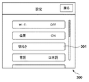
図3は、ディスプレイ105に表示される、電子機器100の設定メニュー画面の例を示す図である。設定メニュー画面300には複数の設定項目の各々に対応するボタン画像が含まれ、タッチ入力が検知されると、タッチされた位置に対応するボタン画像が表す項目の設定画面に遷移する。以下の説明では、ボタン画像のような操作可能なGUIオブジェクトに対応した位置でタッチパネル106aの接触が検出されたことを単に「ボタンがタッチされた」のように表現する場合がある。
FIG. 3 is a diagram illustrating an example of a setting menu screen of the
また、設定メニュー画面300がディスプレイ105よりも上下に大きい場合、上下方向に対するドラッグあるいはフリック操作を検知すると、CPU101は操作方向に応じた方向に設定メニュー画面をスクロール表示させる。これにより、ユーザは表示されていないボタン画像を表示させることができる。
If the
つまり、図3に示す設定メニュー画面300の表示時、電子機器100は少なくともタップ、フリック、ドラッグの各操作を受付可能である。設定メニュー画面が表示された状態でタッチオンの状態となると、CPU101は触感発生部113に上下方向へのムーブ操作に対応した触感を発生させる。例えば、図2の対応テーブルに従い、図4(a)に示すように、例えばタッチオンの位置を中心とした所定の範囲内で下から上に複数の位置で触感402を与えることにより、下から上へ移動する触感を指401に与える。図4(a)において円は触感を与える位置を、矢印は位置の経時変化をそれぞれ示している。これによってユーザは、タッチパネル106aにしばらく触れていることで、現在どのようなタッチ操作が可能なのかを触感から認識することができる。なお、下から上へ移動する触感が感じられさえすれば、触感発生部113によってどの位置にどのような大きさの触感を与えるかは任意に設定可能である。例えば、下から上に触感を与える位置を移動させるとともに、徐々に強い触感を与えることで、方向性を強調するなど、様々な移動パターンを採用することができる。
That is, when the
図5(a)は、図3の状態から明るさボタン301がタッチされた場合にCPU101がディスプレイ105に表示させる明るさ設定画面の例である。明るさ設定画面500には操作可能なGUIオブジェクトとしてスライダー501が含まれる。CPU101は、スライダー501のドラッグ操作に応じてスライダー501の表示位置をバー502に沿って変更するとともに、スライダー501の位置に応じて画面輝度を変更する。すなわち、明るさ設定画面500では、スライダー501がタッチされた状態で受付可能な操作は左右方向へのムーブ操作である。
FIG. 5A is an example of a brightness setting screen that the
従って、CPU101は、明るさ設定画面500を表示中に、スライダー501が所定時間以上タッチされる(タッチオン)と、触感発生部113に、左右方向へのムーブ操作を通知するための触感を発生させる。例えば、図2の対応テーブルに従い、図5(b)に示すように、タッチ位置を中心とする近傍領域内で左から右に、複数の位置において触感を順次発生させる。これによってユーザは、スライダー501に触れていると、スライダー501を左右にドラッグする操作が可能であることを触感から認識することができる。
Therefore, when the
上述したような、図3に示した設定メニュー画面300の表示中に明るさボタン301がタッチされ、図5(a)の明るさ設定画面500で明るさの変更操作が行われる場合のCPU101の処理について、図6に示すフローチャートを用いて説明する。図6のフローチャートに示す制御動作は、不揮発性メモリ103に記憶されたプログラムをメモリ102に展開してCPU101が実行することにより実施される。図6の処理は例えば、操作部106が操作されて、設定メニューの表示指示が入力されたことによって開始される。
When the
S601でCPU101は、不揮発性メモリ103に記憶された設定メニュー画面300のデータに基づいて表示用の映像信号を生成し、この映像信号をディスプレイ105に出力することで、図4(a)の設定メニュー画面300をディスプレイ105に表示する。なお、GUIオブジェクトを表示する場合、GUIオブジェクトデータの読み出し、読み出したGUIオブジェクトデータに基づく映像信号の生成、生成した映像信号のディスプレイ105への出力制御が行われる。ただし、以下では、説明が煩雑にならないよう、CPU101が設定メニュー画面をディスプレイ105に表示する、といった簡略化した記載をする場合がある。
In S <b> 601, the
S602でCPU101は、表示された設定メニュー画面に対するタッチ操作の受付処理を行う。この処理の詳細は図7を用いて後述する。
S603でCPU101は、タッチ操作の受付処理において受け付けられたタッチ操作の種類を判別し、上方向のフリック(ムーブ)操作を受け付けた場合にはS609へ、タップ操作を受け付けた場合にはS604へそれぞれ処理を進める。
In step S <b> 602, the
In step S603, the
S609で、CPU101は、ムーブの距離またはフリックの速度等に応じた量、設定メニュー画面300を上にスクロール表示させ、S602に処理を戻す。スクロール後の表示状態の例を図4(b)に示す。
In step S <b> 609, the
S604でCPU101は、タップ操作がなされたGUIボタンに応じた設定画面をディスプレイに表示する。上述の通り、ここでは明るさの調整操作に関する処理を説明する便宜上、明るさボタン301に対するタップ操作が受け付けられたものとし、図5(a)に示した明るさ設定画面500をディスプレイ105に表示する。ただし、実際には表示されているGUIボタンのうち、どれに対してタップ操作が受け付けられたに応じて、以後の処理を分岐させる。
In step S604, the
図5(a)に示した明るさ設定画面500をディスプレイ105に表示すると、CPU101はS605の明るさ設定画面におけるタッチ操作受付処理を実行する。この処理の詳細については図8を用いて後述する。
When the
S606でCPU101は、明るさ設定画面におけるタッチ操作受付処理で受け付けたタッチ操作を判別し、左方向のムーブ操作を受け付けた場合はS607へ、右方向へのムーブ操作を受け付けた場合はS608へそれぞれ処理を進める。また、「戻る」ボタンのタップ操作を受け付けた場合、CPU101は処理をS601に戻し、再びディスプレイ105に設定メニュー画面300(図3)を表示させる。
In step S606, the
S607でCPU101は、ムーブ操作の量に応じて、スライダー501の表示位置の移動させるとともに、ディスプレイ105の輝度を低下させ、処理をS605へ戻す。
S608でCPU101は、ムーブ操作の量に応じて、スライダー501の表示位置の移動させるとともに、ディスプレイ105の輝度を増加させ、処理をS605へ戻す。
In step S <b> 607, the
In S608, the
次に、図6のS602における設定メニュー画面におけるタッチ操作受付処理の詳細について、図7のフローチャートを用いて説明する。
S702でCPU101は、タッチダウン状態が検出されたか判別する。
Next, details of the touch operation reception process on the setting menu screen in S602 of FIG. 6 will be described using the flowchart of FIG.
In step S702, the
S703でCPU101は、タッチダウン状態の継続時間を測定するため、システムタイマー112をスタートさせる。なお、システムタイマー112が常時動作している場合には、システムタイマー112の出力値のカウントを開始する。
In S703, the
S704でCPU101は、時間測定を開始してから所定時間(ここでは2秒とする)経過したかどうかを判別し、2秒以上経過していればS707へ、2秒経過していなければS705へ、それぞれ処理を進める。S707へ移行するのは、タッチダウン状態が検出されてから2秒以上、上方向へのムーブ状態(図3の表示状態が下方向へスクロールできない状態のため、便宜上上方向についてのみ考慮している)もタッチアップ状態も検出されなかった場合である。
In S704, the
このように本実施形態では、タッチダウンが検出されてから、受付可能なタッチ操作が受け付けられずに所定時間タッチオンの状態が継続すると、その時点で受け付け可能な操作を触感によって通知する。なお、受付可能な全てのタッチ操作を触感によって通知しなくてもよい。例えば、GUIボタンがタップ操作を受け付けることのように、通知するまでもなく受け付けられることが理解される操作については、触感による通知から除外してもよい。これにより、多種の操作を触感により通知することによってユーザが煩わしいと感じたり、結局どのような操作が可能なのか分からなくなるといったことを防ぐことができる。また、触感によって通知するタッチ操作の種類は、タッチオンが検出されている位置に対応したGUIオブジェクトに対して受付可能なものとしてもよい。例えば、画面内に複数のGUIオブジェクト(背景を含む)が存在し、オブジェクトごとに受け付け可能な操作が異なる場合、タッチオンが検出されている位置で受付可能なタッチ操作のみを触感で通知してもよい。 As described above, in this embodiment, when a touch-down state continues for a predetermined time without accepting an acceptable touch operation after the touchdown is detected, the acceptable operation at that time is notified by tactile sensation. It is not necessary to notify all touch operations that can be accepted by tactile sensation. For example, operations that are understood to be accepted without notification, such as a GUI button accepting a tap operation, may be excluded from notification by tactile sensation. Accordingly, it is possible to prevent the user from feeling troublesome by notifying various operations by tactile sensation or not knowing what operation is possible after all. In addition, the type of touch operation notified by tactile sensation may be acceptable for a GUI object corresponding to the position where touch-on is detected. For example, when there are a plurality of GUI objects (including the background) on the screen and the operations that can be accepted are different for each object, only the touch operations that can be accepted at the position where the touch-on is detected can be notified by tactile sensation. Good.
S707でCPU101は、タッチパネル106aに触れているユーザの指に上方向のフリック操作に対応した触感を与えるよう、触感発生部113を図2の表に記載されているように制御する。なお、上下両方向のフリック操作を受付可能な場合、上方向のフリック操作に対応した触感と下方向のフリック操作に対応した触感とを交互に提供するようにすることができる。
In step S <b> 707, the
S708でCPU101は、S703でスタートしたシステムタイマー112またはそのカウント動作を停止し、計時タイマーをリセットする(0にして止める)。
S709でCPU101は、タッチアップを検出したかどうかを判別し、タッチアップを検出すると処理をS702から繰り返す。タッチアップが検出されなければ、CPU101は検出されるまで待機する。なお、タッチアップが検出されなければ、S703に処理を戻すようにしてもよい。こうするとユーザは、触感を感じてからタッチしている指を上方向にムーブさせることで、スクロールを指示することができる。
In step S708, the
In step S709, the
S705でCPU101は、上方向のムーブ状態を検出したかどうかを判別し、検出した場合は処理をS710に進め、上方向のフリック操作を受け付けたことを表す情報を受け付け処理結果に設定して、処理をS712に進める。上方向のムーブ状態を検出していない場合、CPU101は処理をS706へ進め、タッチアップを検出したかどうか判別する。
In step S705, the
S706においてCPU101は、タッチアップを検出していなければ処理をS704に戻す。タッチアップを検出した場合、CPU101は処理をS711に進め、タップ操作を受け付けたことを表す情報を受け付け処理結果に設定して、処理をS712に進める。
S712でCPU101は、S708と同様にタイマーをリセットし、図6のS603へ進む。
In S706, the
S712 in CPU101 similarly resets the timer and S70 8, the process proceeds to S603 of FIG.
次に、図6のS605における明るさ設定画面におけるタッチ操作受付処理の詳細について、図8のフローチャートを用いて説明する。
S802でCPU101は、「戻る」ボタンがタップ操作されたかどうかを判別し、タップ操作されていればS816へ進み、処理結果に「戻る」がタップ操作されたことを表す情報を設定し、タッチ操作受付処理を終了する(S606へ処理を移行する)。
S802において、「戻る」ボタンのタップ操作を受け付けていなければ、CPU101は処理をS803へ進める。
Next, details of the touch operation reception process on the brightness setting screen in S605 of FIG. 6 will be described using the flowchart of FIG.
In step S802, the
If the tap operation of the “return” button is not accepted in S802, the
S803でCPU101は、タッチダウン状態が検出されたか判別する。なお、本実施形態では、明るさ設定画面500で操作可能なGUIオブジェクトは「戻る」ボタン以外はスライダー501のみであるため、タッチダウン状態がスライダー501に対応する領域で検出されたかどうかを判別してもよい。
In step S803, the
S804でCPU101は、タッチダウン状態の継続時間を測定するため、システムタイマー112をスタートさせる。なお、システムタイマー112が常時動作している場合には、システムタイマー112の出力値のカウントを開始する。
In step S804, the
S805でCPU101は、時間測定を開始してから所定時間(ここでは2秒とする)経過したかどうかを判別し、2秒以上経過していればS809へ、2秒経過していなければS806へ、それぞれ処理を進める。S809へ移行するのは、タッチダウン状態が検出されてから2秒以上、左右方向へのムーブ状態もタッチアップ状態も検出されなかった場合である。
In S805, the
このように本実施形態では、タッチパネル106aに対する接触入力が予め定められた条件を満たしたことに応じて、その時点で受け付け可能な操作を触感によって通知する。ここでは一例として、タッチダウンが検出されてから、受付可能なタッチ操作が受け付けられずに所定時間(2秒)タッチオンの状態が継続することを条件として用いたが、他の条件を用いてもよい。また、条件は状況に応じて異ならせてもよい。
As described above, in the present embodiment, when the touch input to the
S809でCPU101は、タッチパネル106aに触れているユーザの指に右方向のフリック操作に対応した触感を与えるよう、触感発生部113を図2の表に記載されているように制御する。なお、図5(b)に示すような、左右両方向のフリック操作を受付可能な場合、右方向のフリック操作に対応した触感と左方向のフリック操作に対応した触感とを交互に提供するようにすることができる。スライダー501が左右端にあり、一方向にしか移動できない場合には、移動可能な方向のフリック操作に対応した触感のみを与えるようにしてもよい。
In step S809, the
S810でCPU101は、S804でスタートしたシステムタイマー112またはそのカウント動作を停止し、計時タイマーをリセットする(0にして止める)。
S811でCPU101は、タッチアップを検出したかどうかを判別し、タッチアップを検出すると処理をS803から繰り返す。タッチアップが検出されなければ、CPU101は検出されるまで待機する。なお、所定時間タッチアップが検出されなければ、S804に処理を戻すようにしてもよい。
In step S810, the
In step S811, the
S806でCPU101は、右方向のムーブ状態を検出したかどうかを判別し、検出した場合は処理をS812に進め、右方向のフリック操作を受け付けたことを表す情報を受け付け処理結果に設定して、処理をS815に進める。右方向のムーブ状態を検出していない場合、CPU101は処理をS807へ進め、左方向のムーブ状態を検出したかどうかを判別する。左方向のムーブ状態を検出した場合、CPU101は処理をS813に進め、左方向のフリック操作を受け付けたことを表す情報を受け付け処理結果に設定して、処理をS815に進める。
S815でCPU101は、S810と同様にタイマーをリセットし、図6のS603へ進む。
In step S806, the
S815 in CPU101 resets the timer in the same manner as
S806,S807で左右方向のムーブ状態を検出していない場合、CPU101は処理をS808へ進め、タッチアップを検出したかどうか判別する。
S808においてCPU101は、タッチアップを検出していなければ処理をS805に戻す。タッチアップを検出した場合、CPU101は処理をS814に進め、S808と同様にタイマーをリセットし、処理をS802に戻す。
When the left and right move states are not detected in S806 and S807, the
In step S808, if the
以上説明したように本実施形態によれば、受付可能なタッチ操作を、触感によってユーザに伝えるようにした。そのため、ガイダンス表示を行う場合のように、表示が指やスタイラスで隠されてしまったり、ガイダンス表示によって他のオブジェクトが隠されてしまったりする問題が生じない。また、専用の表示領域を設ける必要もない。さらに、音声ガイダンスを用いる場合の問題も発生しない。 As described above, according to the present embodiment, a touch operation that can be accepted is transmitted to the user by tactile sensation. Therefore, there is no problem that the display is hidden by a finger or a stylus, and other objects are hidden by the guidance display as in the case of performing the guidance display. Further, it is not necessary to provide a dedicated display area. Furthermore, there is no problem when using voice guidance.
また、タッチダウンが検出された直後ではなく、受付可能なタッチ操作が一定時間検出されなかった時点で触感による通知を行うようにしている。そのため、どのようなタッチ操作が利用可能か理解しているユーザは、触感による通知を受けることなく所望のタッチ操作を行うことができ、使い勝手がよい。一方、利用可能な操作が分からない場合にはタッチを継続するだけで触感による通知を得られるので、その点においても使い勝手がよい。 Further, not only immediately after the touchdown is detected, but also when a touch operation that can be accepted is not detected for a certain period of time, notification by tactile sensation is performed. Therefore, a user who understands what kind of touch operation can be used can perform a desired touch operation without receiving notification by tactile sensation, which is easy to use. On the other hand, when an available operation is not known, a notification by tactile sensation can be obtained simply by continuing the touch, which is also convenient in that respect.
<第2の実施形態>
次に、本発明の第2の実施形態について説明する。本実施形態では、複数のタッチ操作を受付可能な際に、触感による通知を行う具体例を説明する。なお、説明および理解を容易にするため、本実施形態に係る電子機器の機能構成およびタッチ操作と触感との対応関係は第1の実施形態と同様とする。
<Second Embodiment>
Next, a second embodiment of the present invention will be described. In this embodiment, a specific example in which notification by tactile sensation is performed when a plurality of touch operations can be accepted will be described. For ease of explanation and understanding, the functional configuration of the electronic device according to the present embodiment and the correspondence relationship between the touch operation and the tactile sensation are the same as those in the first embodiment.
図9(a)は、記録媒体108に保存されている複数の画像データを一覧表示する画面の一例としてのインデックス画面を示している。本実施形態の電子機器100は、ディスプレイ105にインデックス画面が表示されている際に、左右方向へのフリック(ムーブ)、タップ、ピンチイン、ピンチアウトという複数のタッチ操作を受付可能であるとする。
FIG. 9A shows an index screen as an example of a screen for displaying a list of a plurality of image data stored in the
図9(b)〜(f)は、図9(a)に示すインデックス画面において、受付可能な各タッチ操作が行われた場合の画面の変化の例を示している。図9(b)が右方向フリック、図9(c)が左方向フリック、図9(d)がタップ、図9(e)がピンチイン、図9(f)がピンチアウトにそれぞれ対応する。 FIGS. 9B to 9F show examples of screen changes when each receivable touch operation is performed on the index screen shown in FIG. 9A. 9B corresponds to a right flick, FIG. 9C corresponds to a left flick, FIG. 9D corresponds to a tap, FIG. 9E corresponds to a pinch-in, and FIG. 9F corresponds to a pinch-out.
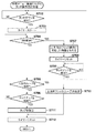
インデックス画面において受け付けたタッチ操作に応じたこれらの画面遷移動作について、図10に示すフローチャートを用いて説明する。
S1001でCPU101は、記録媒体108に保存されている画像データを読み出し画像処理部104でサムネイル化し、不揮発性メモリ103に保存されているデータとレイアウトしてインデックス画面をディスプレイ105に表示する(図9(a))
These screen transition operations corresponding to the touch operation received on the index screen will be described with reference to the flowchart shown in FIG.
In step S1001, the
S1002でCPU101は、タッチダウン状態が検出されるのを待機し、タッチダウン状態が検出されたら処理をS1003に進める。
In step S1002, the
S1003でCPU101は、タッチダウン状態の継続時間を測定するため、システムタイマー112をスタートさせる。なお、システムタイマー112が常時動作している場合には、システムタイマー112の出力値のカウントを開始する。
In S1003, the
S1004でCPU101は、時間測定を開始してから所定時間(ここでは2秒とする)経過したかどうかを判別し、2秒以上経過していればS1016へ、2秒経過していなければS1005へ、それぞれ処理を進める。S1016へ移行するのは、タッチダウン状態が検出されてから2秒以上、左右方向へのフリック操作、ピンチイン操作、ピンチアウト操作、タッチアップ状態のいずれも検出されなかった場合である。S1016においてCPU101は触感制御処理を行う。触感制御処理の詳細については後述する。
In S1004, the
S1005でCPU101は、右方向のフリック状態を検出したかどうかを判別し、検出した場合は処理をS1012に進め、インデックス画面を右方向にスクロール表示する。なお、本実施形態では、インデックス画面はサムネイルを時系列(例えば撮影日時などによる)順に並べて表示しており、右方向へのスクロール表示は時間を遡る方向とする。従って、右方向へのスクロール表示により、図9(b)に示すインデックス画面では、図9(a)で表示されているサムネイルよりも撮影日時の古い画像データのサムネイルが表示されている。そして、CPU101は、処理をS1017に進める。
In step S1005, the
S1005で右方向のフリック操作を検出していない場合、CPU101は処理をS1006に進め、左方向のフリック操作を検出した場合は処理をS1013に進める。S1013でCPU101は、インデックス画面を左方向にスクロール表示する。左方向へのスクロール表示により、図9(c)に示すインデックス画面では、図9(a)で表示されているサムネイルよりも撮影日時の新しい画像データのサムネイルが表示されている。そして、CPU101は、処理をS1017に進める。
If the right flick operation is not detected in S1005, the
S1006で左方向のフリック操作を検出していない場合、CPU101は処理をS1007に進め、ピンチアウト操作を検出したか判別する。CPU101は、ピンチアウト操作を検出していればS1014に、検出していなければS1008にそれぞれ処理を進める。
If the left flick operation is not detected in S1006, the
S1014でCPU101は、ピンチアウト操作による2点間の距離の拡大に応じた倍率でインデックス画面におけるサムネイルを拡大し、画面あたりのサムネイル表示枚数を減らした表示を行う。図9(f)に、ピンチアウト操作時のインデックス画面の表示例を示す。そして、CPU101は、処理をS1017に進める。
In step S1014, the
S1007でピンチアウト操作を検出していない場合、CPU101は処理をS1008に進め、ピンチイン操作を検出したか判別する。CPU101は、ピンチイン操作を検出していればS1015に、検出していなければS1009にそれぞれ処理を進める。
When the pinch-out operation is not detected in S1007, the
S1015でCPU101は、ピンチイン操作による2点間の距離の縮小に応じた倍率でインデックス画面におけるサムネイルを縮小し、画面あたりのサムネイル表示枚数を増やした表示を行う。図9(e)に、ピンチイン操作時のインデックス画面の表示例を示す。そして、CPU101は、処理をS1017に進める。
In step S <b> 1015, the
S1017でCPU101は、タッチアップの検出を待機し、タッチアップを検出すると処理をS1018に進める。S1018でCPU101は、S1003でスタートしたシステムタイマー112またはそのカウント動作を停止し、計時タイマーをリセットする(0にして止める)。そして、CPU101は、処理をS1002から繰り返す。
In step S1017, the
S1005〜S1008で左右フリック操作、ピンチアウト操作、およびピンチイン操作のいずれも検出しなかった場合、CPU101は、S1009でタッチアップを検出したかどうかを判別し、タッチアップを検出すると処理をS1010に進める。タッチアップが検出されなければ、CPU101は処理をS1004に戻す。
If none of the left / right flick operation, the pinch-out operation, and the pinch-in operation is detected in S1005 to S1008, the
S1010でCPU101は、S1003でスタートしたシステムタイマー112またはそのカウント動作を停止し、計時タイマーをリセットする(0にして止める)。この場合、タップ操作が検出されたものとして、CPU101は処理をS1011に進め、タップ位置に該当するサムネイル1つだけがインデックス画面に表示されるように拡大して表示するシングル表示を行う。図9(d)に、シングル表示の例を示す。そして、CPU101は、処理をS1002から繰り返す。
In step S1010, the
次に、図10のS1016における触感制御処理の詳細について、図11に示すフローチャートを用いて説明する。
S1101でCPU101は、S1003で計測を開始してからの経過時間T(秒)に応じて処理を分岐させる。
Next, details of the tactile sensation control processing in S1016 of FIG. 10 will be described using the flowchart shown in FIG.
In S1101, the
経過時間Tが2秒以上4秒未満である場合、CPU101は処理をS1102へ進め、右方向フリック操作に対応した触感を、タッチオンが検出されている位置に与えるよう、触感発生部113を制御する。そして、CPU101は処理をS1108に進める。
If the elapsed time T is not less than 2 seconds and less than 4 seconds, the
経過時間Tが4秒以上6秒未満である場合、CPU101は処理をS1103へ進め、左方向フリック操作に対応した触感を、タッチオンが検出されている位置に与えるよう、触感発生部113を制御する。そして、CPU101は処理をS1108に進める。
When the elapsed time T is not less than 4 seconds and less than 6 seconds, the
経過時間Tが6秒以上8秒未満である場合、CPU101は処理をS1104へ進め、タップ操作に対応した触感を、タッチオンが検出されている位置に与えるよう、触感発生部113を制御する。そして、CPU101は処理をS1108に進める。
When the elapsed time T is 6 seconds or more and less than 8 seconds, the
経過時間Tが8秒以上10秒未満である場合、CPU101は処理をS1105へ進め、ピンチイン操作に対応した触感を、タッチオンが検出されている位置に与えるよう、触感発生部113を制御する。そして、CPU101は処理をS1108に進める。
When the elapsed time T is not less than 8 seconds and less than 10 seconds, the
経過時間Tが10秒以上12秒未満である場合、CPU101は処理をS1106へ進め、ピンチアウト操作に対応した触感を、タッチオンが検出されている位置に与えるよう、触感発生部113を制御する。そして、CPU101は処理をS1108に進める。
When the elapsed time T is not less than 10 seconds and less than 12 seconds, the
経過時間Tが12秒以上である場合、CPU101は処理をS1107へ進め、経過時間Tを2秒に設定して、処理をS1108に進める。
When the elapsed time T is 12 seconds or more, the
S1108でCPU101は、タッチアップを検出したかどうかを判別し、検出していなければ、S1101から再度処理を行う。タッチアップを検出していれば、CPU101は処理をS1109へ進め、システムタイマー112またはそのカウント動作を停止し、計時タイマーをリセットし(0にして止め)、処理をS1002に移行する。
In step S1108, the
このように、本実施形態によれば、現在表示中の画面で受付可能な複数のタッチ操作を示す触感を、タッチオン状態の継続時間に応じて順次発生するよう、CPU101が触感発生部113を制御する。そのため、使用可能なタッチ操作を覚えていない場合や知らない場合に、ユーザはタッチパネルの(例えば同じ場所を)指で触った状態を維持することで、現在使用可能な複数のタッチ操作を一通り知ることが可能である。また、タッチアップが検出されるまで触感による通知を繰り返し行うため、1回の通知でははっきりと認知できなかったタッチ操作があった場合には、タッチアップせずに触れ続ければよいため、使い勝手がよい。
As described above, according to the present embodiment, the
<第3の実施形態>
次に、本発明の第3の実施形態について説明する。本実施形態では、触感による通知を行うタイミングを第1および第2の実施形態と異ならせたものである。第1および第2の実施形態では、タッチダウンの検出後、タッチアップならびに受付可能なタッチ操作が検出されずに所定時間経過したことに応じて、受付可能なタッチ操作に対応する触感を発生させていた。本実施形態では、タッチダウンの検出からの経過時間ではなく、ユーザによる操作入力が所定時間検出されなかった場合、次にタッチダウン状態が検出された際に触感による通知を行うことを特徴とする。なお、説明および理解を容易にするため、本実施形態に係る電子機器の機能構成およびタッチ操作と触感との対応関係は第1および第2の実施形態と同様とする。
<Third Embodiment>
Next, a third embodiment of the present invention will be described. In the present embodiment, the timing for notification by tactile sensation is different from that in the first and second embodiments. In the first and second embodiments, after a touch-down is detected, a touch feeling corresponding to an acceptable touch operation is generated in response to a lapse of a predetermined time without detecting a touch-up or acceptable touch operation. It was. In the present embodiment, when an operation input by the user is not detected for a predetermined time instead of an elapsed time since the detection of the touchdown, a tactile notification is performed when the touchdown state is detected next. . For ease of explanation and understanding, the functional configuration of the electronic device according to the present embodiment and the correspondence between the touch operation and the tactile sensation are the same as those in the first and second embodiments.
ここでは、理解および説明を容易にするため、第2の実施形態で説明したインデックス画面(図9(a))を表示した後の、本実施形態の電子機器100のCPU101の動作を例として、本実施形態における操作通知動作を説明する。
Here, for ease of understanding and explanation, the operation of the
図12は、本実施形態の電子機器100における操作通知動作を説明するためのフローチャートである。
S1201でCPU101は、記録媒体108に保存されている画像データを読み出し画像処理部104でサムネイル化し、不揮発性メモリ103に保存されているデータと一緒にディスプレイ105に表示する(図9(a))。
FIG. 12 is a flowchart for explaining an operation notification operation in the
In step S1201, the
S1202でCPU101は、システムタイマー112をスタートさせる。なお、システムタイマー112が常時動作している場合には、システムタイマー112の出力値のカウントを開始する。
In step S1202, the
S1203でCPU101は、システムタイマー112がスタートしてから所定時間(ここでは5秒とする)以上経過したかどうかを判別し、5秒以上経過していれば処理をS1204へ、5秒経過していなければ処理をS1206へ進める。
In step S1203, the
S1204でCPU101は、タッチダウン状態を検出したかどうか判別する。タッチダウン状態を検出していない場合、検出されるまで待機する。タッチダウン状態を検出した場合、CPU101はS1205で触感制御処理を行う。この触感制御処理は、図11を用いて説明したものと同じであってよい。受付可能なタッチ操作が1つであれば、S1102で触感による通知を行った後、直ちにS1109に処理を進めればよい。
In step S1204, the
S1206でCPU101は、受付可能なタッチ操作を検出したかどうかを判別し、検出していれば、S1207で、検出したタッチ操作に応じた動作を実行する。ここでの動作は、図10を用いて説明した通りである。なお、タップ操作の場合には、シングル表示を行う。一方、受付可能なタッチ操作を検出していない場合、CPU101は処理をS1203へ戻す。
In step S1206, the
本実施形態によれば、GUI画面を表示してから、受付可能なタッチ操作が検出されずに一定時間以上経過した後、タッチパネルへの接触(タッチダウン)が検出されると、受付可能なタッチ操作を触感によって通知する。一方、一定時間経過前にタッチパネルへの接触が検出されても、触感による通知は行わない。GUI画面表示後、比較的短時間内にタッチ操作を行うユーザは、受付可能なタッチ操作を知っているものと考えられるため、触感による通知を行わないことで、経験を積んだユーザの操作を妨げないようにしている。一方、GUI画面表示後、所定時間内に操作を行わないユーザは不慣れなユーザである可能性が十分考えられるため、タッチダウン検出時にタッチ操作に関する通知を行う。 According to the present embodiment, after the GUI screen is displayed and no touch operation that can be accepted is detected, a touch that can be accepted is detected when a touch (touch down) to the touch panel is detected after a certain period of time has elapsed. Notification of operation by touch. On the other hand, even if contact with the touch panel is detected before a certain time has elapsed, notification by tactile sensation is not performed. Users who perform touch operations within a relatively short period of time after displaying the GUI screen are assumed to know touch operations that can be accepted. I do not disturb. On the other hand, since there is a possibility that a user who does not perform an operation within a predetermined time after displaying the GUI screen is an unfamiliar user, a notification regarding the touch operation is given when touchdown is detected.
<第4の実施形態>
次に、本発明の第4の実施形態について説明する。本実施形態は、第3の実施形態において、GUI画面表示後一定時間経過前にタッチ操作を検出したが、そのタッチ操作が受付可能なものではなかった場合の処理を追加したものである。
本実施形態では、このような場合、ユーザが受付可能なタッチ操作を知らないか、勘違いしているものとして、次にタッチダウン状態が検出された際に触感による通知を行うことを特徴とする。なお、説明および理解を容易にするため、本実施形態に係る電子機器の機能構成およびタッチ操作と触感との対応関係は第1および第2の実施形態と同様とする。
<Fourth Embodiment>
Next, a fourth embodiment of the present invention will be described. In this embodiment, a touch operation is detected in the third embodiment before a fixed time has elapsed after the GUI screen is displayed, but a process is added when the touch operation is not acceptable.
In the present embodiment, in such a case, it is assumed that the user does not know or misunderstand the touch operations that can be accepted, and a touch notification is performed when a touchdown state is detected next time. . For ease of explanation and understanding, the functional configuration of the electronic device according to the present embodiment and the correspondence between the touch operation and the tactile sensation are the same as those in the first and second embodiments.
図13は、本実施形態の電子機器100における操作通知動作を説明するためのフローチャートである。なお、図12と同様の処理については共通の参照数字を付して説明を省略し、異なる処理について説明する。
FIG. 13 is a flowchart for explaining an operation notification operation in the
S1303でCPU101は、間違えフラグがONかどうか判別し、間違えフラグがONならばS1305で間違えフラグをOFFにした後にS1204へ処理を進める。
S1303において間違えフラグがOFFならば、処理をS1203へ進める。
In step S1303, the
If the mistake flag is OFF in S1303, the process proceeds to S1203.
S1203でCPU101は、システムタイマー112がスタートしてから所定時間(ここでは5秒とする)以上経過したかどうかを判別し、5秒以上経過していれば処理をS1204へ、5秒経過していなければ処理をS1308へ進める。
In step S1203, the
S1308でCPU101は、タッチ操作を検出したかどうかを判別し、検出していれば、S1309で、検出したタッチ操作が受付可能なものかどうか(表示中のGUI画面において機能する有効なタッチ操作かどうか)判別する。タッチ操作としては正しいが、表示中のGUI画面において意味のないタッチ操作(例えばインデックス画面の表示中における回転操作)であれば、CPU101は処理をS1310に進め、間違えフラグをONにする。さらにCPU101はS1311でタイマーをリセットして処理をS1202に戻す。
In step S1308, the
これにより、S1303からS1305に処理が移行し、S1203で5秒以上経過したと判別された場合と同様、次にタッチダウン状態を検出した場合にS1205で触感制御処理が行われる。 As a result, the process proceeds from S1303 to S1305, and when it is determined in S1203 that 5 seconds or more have elapsed, the tactile sensation control process is performed in S1205 when the touchdown state is detected next.
本実施形態によれば、GUI画面表示後、受付可能なタッチ操作が検出されずに一定時間以上経過した場合に加え、一定時間経過前に検出したタッチ操作が受付可能なものではなかった場合にも、次にタッチダウン状態が検出された際に触感による通知を行う。そのため、第3の実施形態の効果に加え、誤ったタッチ操作を行ったユーザには所定時間の経過を待つことなく、次の入力のタイミングで正しい入力方法を通知できるという効果を有する。 According to the present embodiment, after the GUI screen is displayed, the touch operation that can be accepted is not detected and the touch operation detected before the predetermined time has passed, in addition to the case where the touch operation has not been detected. In addition, when a touch-down state is detected next, notification by tactile sensation is performed. Therefore, in addition to the effect of the third embodiment, there is an effect that a user who performs an erroneous touch operation can be notified of the correct input method at the next input timing without waiting for the elapse of a predetermined time.
なお、上述の実施形態においてCPU101が行うものとして説明した制御は、1つのCPUが行ってもよいし、複数のCPUが処理を分担することで実現されてもよい。
また、本発明をその好適な実施形態に基づいて詳述してきたが、本発明はこれら特定の実施形態に限られるものではなく、この発明の要旨を逸脱しない範囲の様々な形態も本発明に含まれる。さらに、上述した各実施形態は本発明の一実施形態を示すものにすぎず、各実施形態を適宜組み合わせることも可能である。
In addition, the control demonstrated as what CPU101 performs in the above-mentioned embodiment may be performed by one CPU, and may be implement | achieved when a some CPU shares a process.
Although the present invention has been described in detail based on the preferred embodiments thereof, the present invention is not limited to these specific embodiments, and various forms without departing from the gist of the present invention are also included in the present invention. included. Furthermore, each embodiment mentioned above shows only one embodiment of this invention, and it is also possible to combine each embodiment suitably.
また、上述した実施形態においては、本発明を電子機器に適用した場合を例にして説明したが、タッチパネルを用いたユーザインタフェースを有する任意の装置に適用可能である。本発明を適用可能な電子機器の非限定的な例を述べれば以下の通りである。タッチパッドを有するパーソナルコンピュータ、PDA、携帯電話機、携帯型の画像ビューワ、ディスプレイを備えるプリンタ装置、デジタルフォトフレーム、音楽プレーヤー、ゲーム機、電子ブックリーダーなど。 In the above-described embodiment, the case where the present invention is applied to an electronic device has been described as an example. However, the present invention can be applied to any device having a user interface using a touch panel. Non-limiting examples of electronic devices to which the present invention can be applied are as follows. A personal computer having a touch pad, a PDA, a mobile phone, a portable image viewer, a printer device having a display, a digital photo frame, a music player, a game machine, an electronic book reader, and the like.
(他の実施形態)
本発明は、以下の処理を実行することによっても実現される。即ち、上述した実施形態の機能を実現するソフトウェア(プログラム)をネットワーク又は各種記憶媒体を介してシステム或いは装置に供給し、そのシステム或いは装置のコンピュータ(又はCPUやMPU等)がプログラムコードを読み出して実行する処理である。この場合、そのプログラム、及び該プログラムを記憶した記憶媒体は本発明を構成することになる。
(Other embodiments)
The present invention is also realized by executing the following processing. That is, software (program) that realizes the functions of the above-described embodiments is supplied to a system or apparatus via a network or various storage media, and a computer (or CPU, MPU, etc.) of the system or apparatus reads the program code. It is a process to be executed. In this case, the program and the storage medium storing the program constitute the present invention.
Claims (16)
前記受付手段で受け付けたタッチ操作に応じた処理を行う処理手段と、
前記入力手段にタッチしている部位を通じてタッチを行っているユーザが感知可能な刺激を発生させる触感発生手段と、
前記受付手段で受付可能なタッチ操作のパターンに対応した刺激を生成するように前記触感発生手段を制御する制御手段と、を有する電子機器であって、
前記制御手段は、前記受付手段が受付可能な複数の接触入力のパターンのうち、前記電子機器の動作の状態に応じた有効なパターンに対応した刺激を生成するように前記制御を行うことを特徴とする電子機器。 Accepting means for accepting a touch operation on the input means;
Processing means for performing processing according to the touch operation received by the receiving means;
A tactile sensation generating means for generating a stimulus that can be sensed by a user who is touching through the part touching the input means;
Control means for controlling the tactile sensation generating means so as to generate a stimulus corresponding to a touch operation pattern that can be accepted by the accepting means , and an electronic device comprising:
The control means performs the control so as to generate a stimulus corresponding to an effective pattern corresponding to an operation state of the electronic device among a plurality of contact input patterns that can be received by the receiving means. Electronic equipment.
前記受付手段で受け付けたタッチ操作に応じた処理を行う処理手段と、
前記入力手段にタッチしている部位を通じてタッチを行っているユーザが感知可能な刺激を発生させる触感発生手段と、
前記受付手段で受付可能なタッチ操作のパターンに対応した刺激を生成するように前記触感発生手段を制御する制御手段と、を有し、
前記触感発生手段は、前記入力手段のうちタッチされたことを検知可能なタッチ面のうち一部の位置に対して刺激を発生させることが可能であり、
前記制御手段は、前記受付可能なタッチ操作のパターンに応じて前記触感発生手段が発生させる刺激の位置の移動パターンの異なる刺激を発生させるように前記制御を行うことを特徴とする電子機器。 Accepting means for accepting a touch operation on the input means;
Processing means for performing processing according to the touch operation received by the receiving means;
A tactile sensation generating means for generating a stimulus that can be sensed by a user who is touching through the part touching the input means;
Control means for controlling the tactile sensation generating means so as to generate a stimulus corresponding to a touch operation pattern acceptable by the accepting means,
The tactile sensation generating means can generate a stimulus for a part of the touch surface that can detect that the input means is touched,
The control means, wherein the to that electronic device to perform the control so as to generate different stimuli pattern of movement locus of the stimulation generating said tactile generator in accordance with the pattern of the receivable touch operation .
前記入力手段が前記表示手段に設けられることを特徴とする請求項1乃至5のいずれか1項に記載の電子機器。 A display means;
Electronic device according to any one of claims 1 to 5, characterized in that said input means is provided on the display means.
前記入力手段に対するタッチ操作を受付ける受付ステップと、
前記受付ステップで受け付けたタッチ操作に応じた処理を行う処理ステップと、
前記受付ステップで受付可能なタッチ操作のパターンに対応した刺激を生成するように前記触感発生手段を制御する制御ステップと、を有し、
前記制御ステップでは、前記受付ステップで受付可能な複数の接触入力のパターンのうち、前記電子機器の動作の状態に応じた有効なパターンに対応した刺激を生成するように前記制御を行うことを特徴とする電子機器の制御方法。 A method for controlling an electronic device having a tactile sensation generating means for generating a stimulus that can be sensed by a user who is touching through a part touching an input means,
An accepting step for accepting a touch operation on the input means;
A processing step for performing processing according to the touch operation received in the reception step;
A control step of controlling the tactile sensation generating means so as to generate a stimulus corresponding to a touch operation pattern that can be accepted in the accepting step ,
In the control step, the control is performed so as to generate a stimulus corresponding to an effective pattern corresponding to an operation state of the electronic device among a plurality of contact input patterns that can be received in the reception step. A control method for electronic equipment.
前記入力手段に対するタッチ操作を受付ける受付ステップと、
前記受付ステップで受付けたタッチ操作に応じた処理を行う処理ステップと、
前記受付ステップで受付可能なタッチ操作のパターンに対応した刺激を生成するように前記触感発生手段を制御する制御ステップと、を有し、
前記触感発生手段は、前記入力手段のうちタッチされたことを検知可能なタッチ面のうち一部の位置に対して刺激を発生させることが可能であり、
前記制御ステップでは、前記受付可能なタッチ操作のパターンに応じて前記触感発生手段が発生させる刺激の位置の移動パターンの異なる刺激を発生させるように前記制御を行うことを特徴とする電子機器の制御方法。 A method for controlling an electronic device having a tactile sensation generating means for generating a stimulus that can be sensed by a user who is touching through a part touching an input means,
An accepting step for accepting a touch operation on the input means;
A processing step for performing processing according to the touch operation received in the receiving step;
A control step of controlling the tactile sensation generating means so as to generate a stimulus corresponding to a touch operation pattern that can be accepted in the accepting step,
The tactile sensation generating means can generate a stimulus for a part of the touch surface that can detect that the input means is touched,
In the control step, the control is performed so as to generate a stimulus having a different movement pattern of the position of the stimulus generated by the tactile sensation generating unit according to the acceptable touch operation pattern. Method.
Priority Applications (3)
| Application Number | Priority Date | Filing Date | Title |
|---|---|---|---|
| JP2013109388A JP6231774B2 (en) | 2013-05-23 | 2013-05-23 | Electronic device and control method thereof |
| US14/281,605 US9405370B2 (en) | 2013-05-23 | 2014-05-19 | Electronic device and control method thereof |
| CN201410218472.4A CN104182138B (en) | 2013-05-23 | 2014-05-21 | Electronic device and its control method |
Applications Claiming Priority (1)
| Application Number | Priority Date | Filing Date | Title |
|---|---|---|---|
| JP2013109388A JP6231774B2 (en) | 2013-05-23 | 2013-05-23 | Electronic device and control method thereof |
Publications (3)
| Publication Number | Publication Date |
|---|---|
| JP2014229149A JP2014229149A (en) | 2014-12-08 |
| JP2014229149A5 JP2014229149A5 (en) | 2016-07-07 |
| JP6231774B2 true JP6231774B2 (en) | 2017-11-15 |
Family
ID=51935058
Family Applications (1)
| Application Number | Title | Priority Date | Filing Date |
|---|---|---|---|
| JP2013109388A Active JP6231774B2 (en) | 2013-05-23 | 2013-05-23 | Electronic device and control method thereof |
Country Status (3)
| Country | Link |
|---|---|
| US (1) | US9405370B2 (en) |
| JP (1) | JP6231774B2 (en) |
| CN (1) | CN104182138B (en) |
Families Citing this family (8)
| Publication number | Priority date | Publication date | Assignee | Title |
|---|---|---|---|---|
| CN105589594B (en) * | 2014-11-06 | 2019-12-31 | 天马微电子股份有限公司 | Electronic device and operation control method of electronic device |
| JP6872883B2 (en) * | 2016-11-09 | 2021-05-19 | シャープ株式会社 | Display control device, display system, display method and program |
| CN106774854A (en) * | 2016-11-29 | 2017-05-31 | 惠州Tcl移动通信有限公司 | The system and method for automatic vibration when a kind of mobile terminal display screen rotates |
| KR20180103547A (en) * | 2017-03-10 | 2018-09-19 | 삼성전자주식회사 | Portable apparatus and a screen control method thereof |
| JP6961451B2 (en) * | 2017-10-12 | 2021-11-05 | キヤノン株式会社 | Electronic devices, their control methods and programs |
| US10921854B2 (en) * | 2018-09-06 | 2021-02-16 | Apple Inc. | Electronic device with sensing strip |
| JP7183778B2 (en) * | 2018-12-26 | 2022-12-06 | セイコーエプソン株式会社 | Display method and display device |
| JP2022012116A (en) * | 2020-07-01 | 2022-01-17 | コニカミノルタ株式会社 | Information processing apparatus, control method thereof, and program |
Family Cites Families (25)
| Publication number | Priority date | Publication date | Assignee | Title |
|---|---|---|---|---|
| JP3888099B2 (en) * | 2001-08-17 | 2007-02-28 | 富士ゼロックス株式会社 | Touch panel device |
| JP2004319255A (en) * | 2003-04-16 | 2004-11-11 | Equos Research Co Ltd | Pseudo tactile presentation device |
| US8405618B2 (en) * | 2006-03-24 | 2013-03-26 | Northwestern University | Haptic device with indirect haptic feedback |
| JP4918314B2 (en) | 2006-09-06 | 2012-04-18 | クラリオン株式会社 | Input reception device with touch panel |
| JP4811206B2 (en) * | 2006-09-12 | 2011-11-09 | トヨタ自動車株式会社 | Input device |
| KR20080048837A (en) * | 2006-11-29 | 2008-06-03 | 삼성전자주식회사 | Apparatus and method for outputting tactile feedback on display device |
| KR101424259B1 (en) * | 2007-08-22 | 2014-07-31 | 삼성전자주식회사 | Method and apparatus for providing input feedback in portable terminal |
| US20090219252A1 (en) * | 2008-02-28 | 2009-09-03 | Nokia Corporation | Apparatus, method and computer program product for moving controls on a touchscreen |
| US20090303175A1 (en) * | 2008-06-05 | 2009-12-10 | Nokia Corporation | Haptic user interface |
| KR101498623B1 (en) * | 2008-06-25 | 2015-03-04 | 엘지전자 주식회사 | Mobile Terminal Capable of Previewing Different Channel |
| US20100013613A1 (en) * | 2008-07-08 | 2010-01-21 | Jonathan Samuel Weston | Haptic feedback projection system |
| US10289199B2 (en) * | 2008-09-29 | 2019-05-14 | Apple Inc. | Haptic feedback system |
| KR101553842B1 (en) * | 2009-04-21 | 2015-09-17 | 엘지전자 주식회사 | Mobile terminal providing multi haptic effect and control method thereof |
| CN101907922B (en) * | 2009-06-04 | 2015-02-04 | 新励科技(深圳)有限公司 | Touch and touch control system |
| JP5371626B2 (en) | 2009-08-18 | 2013-12-18 | キヤノン株式会社 | Display control device, display control device control method, program, and storage medium |
| JP4846857B2 (en) * | 2010-03-03 | 2011-12-28 | 株式会社東芝 | Information processing apparatus and input control method |
| JP2011248400A (en) * | 2010-05-21 | 2011-12-08 | Toshiba Corp | Information processor and input method |
| JP5452404B2 (en) * | 2010-07-27 | 2014-03-26 | 京セラ株式会社 | Tactile presentation device |
| JP6203637B2 (en) * | 2010-11-09 | 2017-09-27 | コーニンクレッカ フィリップス エヌ ヴェKoninklijke Philips N.V. | User interface with haptic feedback |
| JP5862271B2 (en) * | 2010-12-29 | 2016-02-16 | 株式会社リコー | User interface device, image forming apparatus, user interface control method and program |
| JP5639527B2 (en) * | 2011-04-01 | 2014-12-10 | 京セラ株式会社 | Electronics |
| US9285880B2 (en) * | 2012-12-26 | 2016-03-15 | Panasonic Intellectual Property Management Co., Ltd. | Touch panel device and method of controlling a touch panel device |
| KR102184288B1 (en) * | 2013-01-17 | 2020-11-30 | 삼성전자주식회사 | Mobile terminal for providing haptic effect with an input unit and method therefor |
| KR20140097902A (en) * | 2013-01-30 | 2014-08-07 | 삼성전자주식회사 | Mobile terminal for generating haptic pattern and method therefor |
| JP2014222488A (en) * | 2013-05-14 | 2014-11-27 | 株式会社東芝 | Drawing device and drawing system |
-
2013
- 2013-05-23 JP JP2013109388A patent/JP6231774B2/en active Active
-
2014
- 2014-05-19 US US14/281,605 patent/US9405370B2/en active Active
- 2014-05-21 CN CN201410218472.4A patent/CN104182138B/en active Active
Also Published As
| Publication number | Publication date |
|---|---|
| JP2014229149A (en) | 2014-12-08 |
| US9405370B2 (en) | 2016-08-02 |
| US20140347296A1 (en) | 2014-11-27 |
| CN104182138B (en) | 2018-10-09 |
| CN104182138A (en) | 2014-12-03 |
Similar Documents
| Publication | Publication Date | Title |
|---|---|---|
| JP6231774B2 (en) | Electronic device and control method thereof | |
| AU2022202593B2 (en) | Character recognition on a computing device | |
| US20210191582A1 (en) | Device, method, and graphical user interface for a radial menu system | |
| JP6157215B2 (en) | Display control apparatus and control method thereof | |
| KR102242348B1 (en) | Input device and user interface interactions | |
| EP3469470B1 (en) | Accelerated scrolling | |
| JP6071372B2 (en) | Electronic device and control method of electronic device | |
| JP6584084B2 (en) | Display control apparatus, control method therefor, program, and storage medium | |
| JP5911321B2 (en) | Display control device and control method of display control device | |
| JP6061528B2 (en) | Operating device, control method and program thereof, and recording medium | |
| US10306047B2 (en) | Mechanism for providing user-programmable button | |
| JP6971573B2 (en) | Electronic devices, their control methods and programs | |
| JP2018132831A (en) | Electronic device, electronic device control method and program | |
| JP2019121313A (en) | Electronic apparatus, information processing method, program and storage medium |
Legal Events
| Date | Code | Title | Description |
|---|---|---|---|
| A521 | Written amendment |
Free format text: JAPANESE INTERMEDIATE CODE: A523 Effective date: 20160519 |
|
| A621 | Written request for application examination |
Free format text: JAPANESE INTERMEDIATE CODE: A621 Effective date: 20160519 |
|
| A977 | Report on retrieval |
Free format text: JAPANESE INTERMEDIATE CODE: A971007 Effective date: 20170215 |
|
| A131 | Notification of reasons for refusal |
Free format text: JAPANESE INTERMEDIATE CODE: A131 Effective date: 20170403 |
|
| A521 | Written amendment |
Free format text: JAPANESE INTERMEDIATE CODE: A523 Effective date: 20170531 |
|
| TRDD | Decision of grant or rejection written | ||
| A01 | Written decision to grant a patent or to grant a registration (utility model) |
Free format text: JAPANESE INTERMEDIATE CODE: A01 Effective date: 20170922 |
|
| A61 | First payment of annual fees (during grant procedure) |
Free format text: JAPANESE INTERMEDIATE CODE: A61 Effective date: 20171020 |
|
| R151 | Written notification of patent or utility model registration |
Ref document number: 6231774 Country of ref document: JP Free format text: JAPANESE INTERMEDIATE CODE: R151 |