JP6229472B2 - Seat slide device - Google Patents

Seat slide device Download PDF

Info

Publication number
JP6229472B2
JP6229472B2 JP2013258294A JP2013258294A JP6229472B2 JP 6229472 B2 JP6229472 B2 JP 6229472B2 JP 2013258294 A JP2013258294 A JP 2013258294A JP 2013258294 A JP2013258294 A JP 2013258294A JP 6229472 B2 JP6229472 B2 JP 6229472B2
Authority
JP
Japan
Prior art keywords
locking
memory
auxiliary member
hole
pin
Prior art date
Legal status (The legal status is an assumption and is not a legal conclusion. Google has not performed a legal analysis and makes no representation as to the accuracy of the status listed.)
Expired - Fee Related
Application number
JP2013258294A
Other languages
Japanese (ja)
Other versions
JP2015113070A (en
Inventor
二本松 英雄
英雄 二本松
Current Assignee (The listed assignees may be inaccurate. Google has not performed a legal analysis and makes no representation or warranty as to the accuracy of the list.)
Aisin Corp
Original Assignee
Aisin Seiki Co Ltd
Aisin Corp
Priority date (The priority date is an assumption and is not a legal conclusion. Google has not performed a legal analysis and makes no representation as to the accuracy of the date listed.)
Filing date
Publication date
Application filed by Aisin Seiki Co Ltd, Aisin Corp filed Critical Aisin Seiki Co Ltd
Priority to JP2013258294A priority Critical patent/JP6229472B2/en
Publication of JP2015113070A publication Critical patent/JP2015113070A/en
Application granted granted Critical
Publication of JP6229472B2 publication Critical patent/JP6229472B2/en
Expired - Fee Related legal-status Critical Current
Anticipated expiration legal-status Critical

Links

Images

Description

本発明は、シートスライド装置、特に車両用のシートスライド装置に関する。   The present invention relates to a seat slide device, and more particularly to a vehicle seat slide device.

従来、車両用のシートスライド装置として、シート位置のメモリ機能を有するシートスライド装置があった。そして、このシートスライド装置として、ロアレール及びアッパレールと、ロアレール及びアッパレールの相対移動を規制するロック部材と、シートバックの前倒しに連動してロアレールに係止されるメモリピースと、アッパレールに設けられ、メモリピースの前部と当接可能な受け部と、アッパレールに設けられ、メモリピースの後部と当接可能な曲成部及びメモリピースをロアレールに係止する押圧部を有するメモリプレートと、を備える装置が知られていた(特許文献1)。   Conventionally, there has been a seat slide device having a seat position memory function as a vehicle seat slide device. As the seat slide device, a lower rail and an upper rail, a lock member that restricts relative movement of the lower rail and the upper rail, a memory piece that is locked to the lower rail in conjunction with the forward tilting of the seat back, and an upper rail are provided. An apparatus comprising: a receiving portion capable of contacting the front portion of the piece; a bent portion provided on the upper rail and capable of contacting the rear portion of the memory piece; and a memory plate having a pressing portion for locking the memory piece to the lower rail. (Patent Document 1).

具体的にこのシートスライド装置においては、メモリピースがロアレールから離脱しているときは、受け部及び曲成部でメモリピースを保持してアッパレールに連動して移動させる。そして、メモリピースがロアレールに係止されているときは、押圧部でメモリピースをロアレールに係止する。このメモリピースは、下側に突出する係止ピン(メモリピン)を含む係止体を有している。また、ロアレールの底壁部には、複数の係止孔が所定の間隔をもって並設されている。そして、シートを前倒しして、ロック部材による規制が解除されると、同時に係止ピンが下方に移動される。これにより、係止ピンの先端は、係止ピンの下側に位置する係止孔を貫通し、メモリピースがロアレールに係止される。   Specifically, in this seat slide device, when the memory piece is detached from the lower rail, the memory piece is held by the receiving portion and the bending portion and moved in conjunction with the upper rail. When the memory piece is locked to the lower rail, the memory piece is locked to the lower rail by the pressing portion. This memory piece has a locking body including a locking pin (memory pin) protruding downward. In addition, a plurality of locking holes are arranged in parallel at predetermined intervals on the bottom wall portion of the lower rail. When the seat is moved forward and the restriction by the lock member is released, the locking pin is simultaneously moved downward. Thereby, the tip of the locking pin passes through the locking hole located on the lower side of the locking pin, and the memory piece is locked to the lower rail.

その後、シートを前方へ移動すると、メモリピースは、メモリプレートの押圧部によって係止された状態に維持される。これにより、メモリピースを残置したままで、シートが前方へ移動される。そして、シートを元位置に戻すために後方へ移動すると、アッパレールの受け部が元位置(メモリ位置)に残置されたメモリピースの前部に当接する。この状態で、ロック部材のロック爪をロアレールのロック孔に挿入し、ロアレール及びアッパレールの相対移動が規制される。このようにして、シート(アッパレール)を元位置に戻すことができる。   Thereafter, when the seat is moved forward, the memory piece is maintained in a state of being locked by the pressing portion of the memory plate. As a result, the seat is moved forward with the memory piece remaining. When the seat is moved backward to return the seat to the original position, the receiving portion of the upper rail comes into contact with the front portion of the memory piece left at the original position (memory position). In this state, the lock claw of the lock member is inserted into the lock hole of the lower rail, and the relative movement of the lower rail and the upper rail is restricted. In this way, the seat (upper rail) can be returned to the original position.

特開2008−247143号公報JP 2008-247143 A

このようなシートスライド装置においては、メモリピンと、ロアレールの係止孔とにクリアランスが設定されている。つまり、係止孔の内径は、メモリピンの外径よりも大きく設計されている。そのため、シートを元位置に戻す際に、アッパレールの受け部がメモリピースの前部に当接すると、メモリピンが係止孔の後側内縁に当接するまでメモリピースが移動してしまう。このように、メモリピンと係止孔との相対位置にずれが生じる様子を、比較例1を参照して説明する。   In such a seat slide device, a clearance is set in the memory pin and the locking hole of the lower rail. That is, the inner diameter of the locking hole is designed to be larger than the outer diameter of the memory pin. Therefore, when the seat is returned to the original position, if the receiving portion of the upper rail contacts the front portion of the memory piece, the memory piece moves until the memory pin contacts the rear inner edge of the locking hole. The manner in which the relative position between the memory pin and the locking hole is thus shifted will be described with reference to Comparative Example 1.

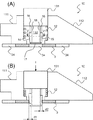
図8A及び図8Bはロック部材のロック爪1023とロアレールのロック孔1035とを示し、図8C及び図8Dは、メモリピン1013とロアレールの係止孔1034とを示す。また、図8A及び図8Cは、メモリピン1013が係止孔1034に挿入されたメモリ時の状態を示し、図8B及び図8Dは、シートを元位置に移動した復帰時の状態を示す。また、図8Aにおいては、メモリ時のロック爪1023の中心線を一点鎖線で示している。図8Bにおいては、メモリ時のロック爪1023の中心線を一点鎖線で示し、復帰時のロック爪1023の中心線を二点鎖線で示している。   8A and 8B show a lock claw 1023 of the lock member and a lower rail lock hole 1035, and FIGS. 8C and 8D show a memory pin 1013 and a lower rail locking hole 1034. FIG. 8A and 8C show a state at the time of memory in which the memory pin 1013 is inserted into the locking hole 1034, and FIGS. 8B and 8D show a state at the time of return when the sheet is moved to the original position. In FIG. 8A, the center line of the lock claw 1023 at the time of memory is indicated by a one-dot chain line. In FIG. 8B, the center line of the lock claw 1023 at the time of memory is indicated by a one-dot chain line, and the center line of the lock claw 1023 at the time of return is indicated by a two-dot chain line.

メモリ状時のメモリピン1013と係止孔1034との間には、クリアランスの差に起因する隙間が生じる。図8Cにおいては、メモリピン1013と係止孔1034の前側内縁との隙間d1と、メモリピン1013と係止孔1034の後側内縁との隙間d2とが生じている。その後、シートを元位置に戻すために、アッパレールを後方に移動させると、メモリピースの前部にアッパレールの受け部が当接する。そして、係止孔の後側内縁に当接するまで、メモリピースが力Fで後方に押される。その結果、アッパレール及びメモリピースは、隙間d2に対応する距離だけ後方に移動する。そのため、図8Dに示すように、復帰時のメモリピン1013と係止孔1034の前側内縁との間には、隙間d1に隙間d2を加えた隙間d3が生じる。   A gap due to a difference in clearance is generated between the memory pin 1013 and the locking hole 1034 in the memory state. In FIG. 8C, a gap d1 between the memory pin 1013 and the front inner edge of the locking hole 1034 and a gap d2 between the memory pin 1013 and the rear inner edge of the locking hole 1034 are generated. Thereafter, when the upper rail is moved backward to return the seat to the original position, the receiving portion of the upper rail comes into contact with the front portion of the memory piece. Then, the memory piece is pushed backward by the force F until it comes into contact with the rear inner edge of the locking hole. As a result, the upper rail and the memory piece move backward by a distance corresponding to the gap d2. Therefore, as shown in FIG. 8D, a gap d3 is formed between the memory pin 1013 at the time of return and the front inner edge of the locking hole 1034 by adding the gap d2 to the gap d1.

一方、メモリ時のロック爪1023は、ロック孔1035から離脱しており、ロアレール及びアッパレールの相対移動の規制は解除されている。その後、シートを元位置に戻すために、アッパレールを後方に移動させると、アッパレールと共にロック爪1023も後方に移動する。その結果、アッパレール及びメモリピースが、隙間d2に対応する距離だけ後方に移動すると、ロック爪1023も隙間d2と同じ距離d4だけ後方に移動する。そのため、図8Bに示すように、ロック爪1023とロック孔1035との相対位置にずれが生じてしまう。これにより、ロック孔1035からずれてしまったロック爪1023は、ロック孔1035への挿入を妨げられてしまう。その結果、ロアレール及びアッパレールの相対移動を規制することができなくなることがある。   On the other hand, the lock claw 1023 at the time of memory is detached from the lock hole 1035, and the restriction on the relative movement of the lower rail and the upper rail is released. Thereafter, when the upper rail is moved rearward in order to return the seat to the original position, the lock claw 1023 also moves rearward together with the upper rail. As a result, when the upper rail and the memory piece move backward by a distance corresponding to the gap d2, the lock claw 1023 also moves backward by the same distance d4 as the gap d2. Therefore, as shown in FIG. 8B, the relative position between the lock claw 1023 and the lock hole 1035 is displaced. As a result, the lock claw 1023 that has been displaced from the lock hole 1035 is prevented from being inserted into the lock hole 1035. As a result, the relative movement of the lower rail and the upper rail may not be restricted.

この状態で、アッパレールがさらに後方に移動すると、ロック爪1023が、矢印Mで示すように元のロック孔1035とは異なる(後方において隣接する)ロック孔1035’に挿入されてしまう。その結果、シートを元位置に復帰させることができなくなるおそれがある。   If the upper rail moves further rearward in this state, the lock claw 1023 is inserted into the lock hole 1035 ′ different from the original lock hole 1035 (adjacent in the rear) as indicated by the arrow M. As a result, the sheet may not be returned to the original position.

この問題を解決するために、メモリピンの先端形状をテーパ状に形付けることが考えられる。このテーパ状の先端を有するメモリピンについて、比較例2を参照して説明する。図9A及び図9Bはロック部材のロック爪2023とロアレールのロック孔2035とを示し、図9C及び図9Dは、メモリピン2013と係止孔2034とを示す。また、図9A及び図9Cは、メモリピン2013が係止孔2034に挿入されたメモリ時の状態を示し、図9B及び図9Dは、シートを元位置に移動した復帰時の状態を示す。   In order to solve this problem, it can be considered that the tip of the memory pin is tapered. The memory pin having the tapered tip will be described with reference to Comparative Example 2. 9A and 9B show the lock claw 2023 of the lock member and the lock hole 2035 of the lower rail, and FIGS. 9C and 9D show the memory pin 2013 and the locking hole 2034. 9A and 9C show a state at the time of memory in which the memory pin 2013 is inserted into the locking hole 2034, and FIGS. 9B and 9D show a state at the time of return when the sheet is moved to the original position.

比較例2のメモリピン2013は、テーパ状の先端を有する。そして、メモリ時のメモリピン2013は、先端が係止孔2034の内縁に当接するまで係止孔2034に挿入される。そのため、メモリピン2013と係止孔2034との間には、図9Cに示すように隙間が生じていない。これにより、メモリ時の係止孔2034の後側内縁とメモリピン2013の隙間に起因する、復帰時の位置ずれは生じない。しかし、シートを元位置に戻すために、アッパレールを後方に移動させると、メモリピースの前部にアッパレールの受け部が当接する。そして、係止孔2034の後側内縁に当接するまで、メモリピースが力Fで後方に押される。その結果、メモリピン2013のテーパ面が係止孔2034の後側内縁に当接する。ここで、大きな力でアッパレールを後方に移動させたときには、メモリピン2013のテーパ面が係止孔2034の後側内縁に乗り上がるおそれがある。この場合、メモリピン2013が後方に向かって斜め上方に移動する共に、メモリピースが後方に移動してしまう。そのため、図9Dに示すように、復帰時のメモリピン2013と係止孔2034の前側内縁との間には、隙間d5が生じてしまう。   The memory pin 2013 of Comparative Example 2 has a tapered tip. The memory pin 2013 at the time of memory is inserted into the locking hole 2034 until the tip comes into contact with the inner edge of the locking hole 2034. Therefore, there is no gap between the memory pin 2013 and the locking hole 2034 as shown in FIG. 9C. As a result, there is no misalignment at the time of return due to the gap between the rear inner edge of the locking hole 2034 at the time of memory and the memory pin 2013. However, when the upper rail is moved backward to return the seat to the original position, the receiving portion of the upper rail comes into contact with the front portion of the memory piece. Then, the memory piece is pushed backward by the force F until it comes into contact with the rear inner edge of the locking hole 2034. As a result, the tapered surface of the memory pin 2013 comes into contact with the rear inner edge of the locking hole 2034. Here, when the upper rail is moved rearward with a large force, the taper surface of the memory pin 2013 may ride on the rear inner edge of the locking hole 2034. In this case, the memory pin 2013 moves obliquely upward toward the rear, and the memory piece moves rearward. Therefore, as shown in FIG. 9D, a gap d5 is generated between the memory pin 2013 at the time of return and the front inner edge of the locking hole 2034.

一方、メモリ時のロック爪2023は、ロック孔2035から離脱しており、ロアレール及びアッパレールの相対移動の規制は解除されている。その後、シートを元位置に戻すために、アッパレールを後方に移動させると、アッパレールと共にロック爪2023も後方に移動する。その結果、アッパレール及びメモリピースが、隙間d5に対応する距離だけ後方に移動すると、ロック爪2023も隙間d5同じ距離d6だけ後方に移動する。そのため、図9Bに示すように、ロック爪2023とロック孔2035との相対位置にずれが生じてしまう。これにより、ロック孔2035からずれてしまったロック爪2023は、ロック孔2035への挿入を妨げられてしまう。その結果、ロアレール及びアッパレールの相対移動を規制することができなくなることがある。   On the other hand, the lock claw 2023 at the time of memory is detached from the lock hole 2035, and the restriction on the relative movement of the lower rail and the upper rail is released. Thereafter, when the upper rail is moved backward to return the seat to the original position, the lock claw 2023 also moves rearward together with the upper rail. As a result, when the upper rail and the memory piece move backward by a distance corresponding to the gap d5, the lock claw 2023 also moves backward by the same distance d6 as the gap d5. Therefore, as shown in FIG. 9B, the relative position between the lock claw 2023 and the lock hole 2035 is displaced. As a result, the lock claw 2023 that is displaced from the lock hole 2035 is prevented from being inserted into the lock hole 2035. As a result, the relative movement of the lower rail and the upper rail may not be restricted.

テーパ状の先端を有するメモリピンであっても、このような状態で、アッパレールがさらに後方に移動すると、ロック爪2023が、矢印Mで示すように元のロック孔2035とは異なる(後方において隣接する)ロック孔2035’に挿入されてしまう。その結果、シートを元位置に復帰させることができなくなるおそれがある。   Even in the case of a memory pin having a tapered tip, when the upper rail moves further rearward in this state, the lock claw 2023 differs from the original lock hole 2035 as indicated by the arrow M (adjacent in the rear). To be inserted into the lock hole 2035 '. As a result, the sheet may not be returned to the original position.

上記課題を解決するため、本発明の一例としてのシートスライド装置は、車両に固定される固定レールと、前記車両のシートを保持すると共に、前記固定レールに対し相対的に移動可能な可動レールと、前記固定レールに対する前記可動レールの移動を規制するロック部材と、前記ロック部材による規制の解除に連動して前記固定レールの係止孔に挿入されると共に、前記係止孔に挿入された状態で前記可動レールの移動を制限するメモリピンと、前記メモリピンに移動可能に支持されると共に、前記メモリピンの挿入時に該メモリピンと共に前記係止孔に挿入できるように構成され、且つ該係止孔への挿入により、該係止孔の内縁に当接する少なくとも一つの係止補助部材とを備える。   In order to solve the above problems, a seat slide device as an example of the present invention includes a fixed rail fixed to a vehicle, a movable rail that holds a seat of the vehicle and is movable relative to the fixed rail. A lock member for restricting movement of the movable rail with respect to the fixed rail, and a state in which the lock rail is inserted into the lock hole in conjunction with the release of the restriction by the lock member and inserted into the lock hole And a memory pin that restricts movement of the movable rail, and is configured to be movably supported by the memory pin and to be inserted into the locking hole together with the memory pin when the memory pin is inserted. And at least one locking auxiliary member that comes into contact with the inner edge of the locking hole by insertion into the hole.

これにより、メモリ時と復帰時との間において、メモリピンと係止孔との間の隙間を埋めることができるので、相対位置のずれの発生を防止できる。そのため、ロック爪とロック孔との相対位置のずれを防止できるので、シートを正確な元位置に復帰させることができる。   As a result, the gap between the memory pin and the locking hole can be filled between the time of memory and the time of return, so that it is possible to prevent the relative position from being shifted. Therefore, since the shift of the relative position between the lock claw and the lock hole can be prevented, the sheet can be returned to the correct original position.

本発明のさらなる特徴は、添付図面を参照して例示的に示した以下の実施例の説明から明らかになる。   Further features of the present invention will become apparent from the following description of embodiments, given by way of example with reference to the accompanying drawings.

シートを示す概略側面図である。It is a schematic side view which shows a sheet | seat. シートスライド装置を示す概略分解斜視図である。It is a schematic exploded perspective view showing a seat slide device. シートスライド装置を長手方向に切った断面を示す概略断面図である。It is a schematic sectional drawing which shows the cross section which cut | disconnected the seat slide apparatus in the longitudinal direction. 第1実施形態に係るメモリピースを示す概略図である。It is the schematic which shows the memory piece which concerns on 1st Embodiment. 第1実施形態に係るメモリ時のメモリピースを示す概略図である。It is the schematic which shows the memory piece at the time of the memory which concerns on 1st Embodiment. 図4Aに示すメモリピンの係止部のV−V断面を示す概略断面図である。It is a schematic sectional drawing which shows the VV cross section of the latching | locking part of the memory pin shown to FIG. 4A. 実施形態1に係るメモリピンの係止部を示す概略分解斜視図である。FIG. 3 is a schematic exploded perspective view showing a locking portion of the memory pin according to the first embodiment. 第2実施形態に係るメモリピースを示す概略図である。It is the schematic which shows the memory piece which concerns on 2nd Embodiment. 第2実施形態に係るメモリ時のメモリピースを示す概略図である。It is the schematic which shows the memory piece at the time of the memory which concerns on 2nd Embodiment. 比較例1に係るメモリ時のロック爪を示す概略図である。6 is a schematic view showing a lock claw at the time of memory according to Comparative Example 1. FIG. 比較例1に係る復帰時のロック爪を示す概略図である。It is the schematic which shows the lock nail | claw at the time of the return which concerns on the comparative example 1. FIG. 比較例1に係るメモリ時のメモリピンを示す概略図である。6 is a schematic diagram showing memory pins in a memory according to Comparative Example 1. FIG. 比較例1に係る復帰時のメモリピンを示す概略図である。6 is a schematic diagram showing a memory pin at return according to Comparative Example 1. FIG. 比較例2に係るメモリ時のロック爪を示す概略図である。It is the schematic which shows the lock nail | claw at the time of the memory which concerns on the comparative example 2. FIG. 比較例2に係る復帰時のロック爪を示す概略図である。It is the schematic which shows the lock nail | claw at the time of the return which concerns on the comparative example 2. FIG. 比較例2に係るメモリ時のメモリピンを示す概略図である。10 is a schematic diagram showing memory pins in a memory according to Comparative Example 2. FIG. 比較例2に係る復帰時のメモリピンを示す概略図である。10 is a schematic diagram showing a memory pin at return according to Comparative Example 2. FIG.

以下、本発明を実施するための例示的な実施形態を、図面を参照して詳細に説明する。ただし、以下の実施形態で説明する寸法、材料、形状、構成要素の相対的な位置等は任意であり、本発明が適用される装置の構成又は様々な条件に応じて変更できる。また、特別な記載がない限り、本発明の範囲は、以下に具体的に記載された実施形態に限定されるものではない。なお、本明細書において、上下とは重力方向における上方向と下方向とにそれぞれ対応する。また、車両のフロント側の方向を前方向といい、車両のリア側の方向を後方向という。   Hereinafter, exemplary embodiments for carrying out the present invention will be described in detail with reference to the drawings. However, dimensions, materials, shapes, relative positions of components, and the like described in the following embodiments are arbitrary and can be changed according to the configuration of the apparatus to which the present invention is applied or various conditions. In addition, unless otherwise specified, the scope of the present invention is not limited to the embodiments specifically described below. In the present specification, “up and down” corresponds to an upward direction and a downward direction in the direction of gravity, respectively. The direction on the front side of the vehicle is referred to as the front direction, and the direction on the rear side of the vehicle is referred to as the rear direction.

[第1実施形態]
図1は、自動車などの車両の前側に搭載される車両用のシート100の概略側面図である。車両の床面200には、車両の前後方向に延在する固定レールとしてのロアレール3が前後一対のブラケット9を介して固定されている。また、ロアレール3には、前後方向に移動できる可動レールとしてのアッパレール4が、ロアレール3に対し相対的に移動可能に取り付けられている。
[First Embodiment]
FIG. 1 is a schematic side view of a vehicle seat 100 mounted on the front side of a vehicle such as an automobile. A lower rail 3 as a fixed rail extending in the front-rear direction of the vehicle is fixed to the floor surface 200 of the vehicle via a pair of front and rear brackets 9. An upper rail 4 as a movable rail that can move in the front-rear direction is attached to the lower rail 3 so as to be movable relative to the lower rail 3.

ロアレール3及びアッパレール4は、シート100の前後方向に直交する幅方向において、それぞれ対をなして配設されている。そして、一対のアッパレール4にはシートクッション7が固定されている。このシートクッション7は、アッパレール4に固定された状態で、ロアレール3に対して前後方向に移動可能である。なお、ロアレール3に対するアッパレール4の移動は、後述するロックレバー22によって規制される。そのため、シート100には、ロックレバー22による規制を解除するためのロック解除ハンドル6が設けられている。また、シートクッション7の後部には、回動軸5周りに揺動可能に支持されたシートバック8が設けられている。このシートバック8は、不図示の調整レバーを操作することにより、図1に点線で示す前傾位置へと前倒しすることができる。   The lower rail 3 and the upper rail 4 are arranged in pairs in the width direction orthogonal to the front-rear direction of the seat 100. A seat cushion 7 is fixed to the pair of upper rails 4. The seat cushion 7 is movable in the front-rear direction with respect to the lower rail 3 while being fixed to the upper rail 4. The movement of the upper rail 4 with respect to the lower rail 3 is regulated by a lock lever 22 described later. Therefore, the seat 100 is provided with a lock release handle 6 for releasing the restriction by the lock lever 22. Further, a seat back 8 is provided at the rear portion of the seat cushion 7 so as to be swingable around the rotation shaft 5. The seat back 8 can be moved forward to a forward inclined position indicated by a dotted line in FIG. 1 by operating an adjustment lever (not shown).

次に、車両用のシートスライド装置1について、図2及び図3に基づいて説明する。図2は、シートスライド装置1の概略分解斜視図である。また、図3は、シートスライド装置1を前後方向に切った断面を示す概略断面図である。なお、左右のロアレール3は、同様の構造を備えており、左右のアッパレール4も、同様の構造を備えている。そのため、以下の説明においては、必要な場合を除いてシートスライド装置1の前方に向かって右側の構造について説明する。   Next, the seat slide apparatus 1 for vehicles is demonstrated based on FIG.2 and FIG.3. FIG. 2 is a schematic exploded perspective view of the seat slide device 1. FIG. 3 is a schematic cross-sectional view showing a cross section of the seat slide device 1 cut in the front-rear direction. The left and right lower rails 3 have the same structure, and the left and right upper rails 4 also have the same structure. Therefore, in the following description, the structure on the right side toward the front of the seat slide apparatus 1 will be described except when necessary.

図2に示すように、シートスライド装置1は、車両に固定されるロアレール3と、車両のシート100を保持すると共に、ロアレール3に対し相対的に移動可能なアッパレール4とを備える。ロアレール3は、前後方向(長手方向)に延在する底壁部32と、底壁部32の幅方向における両端部から上方向に延在する一対の側壁部31とを有している。そして、各側壁部31の先端には、ロアレール3の幅方向における内側に向かって折り返された折返し壁部33が形成されている。また、アッパレール4は、前後方向(長手方向)に延在する蓋壁部42と、蓋壁部42の幅方向における両端部から下方向に延在する一対の側壁部41とを有している。そして、側壁部41の先端には、幅方向における外側に向かって折り返された折返し壁部43が形成されている。   As shown in FIG. 2, the seat slide device 1 includes a lower rail 3 that is fixed to the vehicle, and an upper rail 4 that holds the vehicle seat 100 and is movable relative to the lower rail 3. The lower rail 3 has a bottom wall portion 32 extending in the front-rear direction (longitudinal direction), and a pair of side wall portions 31 extending upward from both ends in the width direction of the bottom wall portion 32. A folded wall portion 33 is formed at the tip of each side wall portion 31 so as to be folded inward in the width direction of the lower rail 3. Further, the upper rail 4 includes a lid wall portion 42 extending in the front-rear direction (longitudinal direction) and a pair of side wall portions 41 extending downward from both end portions in the width direction of the lid wall portion 42. . A folded wall portion 43 is formed at the tip of the side wall portion 41 so as to be folded toward the outside in the width direction.

このロアレール3及びアッパレール4は、略U字状の断面形状を有しており、ロアレール3及びアッパレール4の開口側が互いに突き合わされるように組み合わされる。そして、組み合わせた際には、アッパレール4の折返し壁部43が、ロアレール3の折返し壁部33の内側に配置される。これにより、アッパレール4は、ロアレール3の上方向に抜け止めされる。   The lower rail 3 and the upper rail 4 have a substantially U-shaped cross-sectional shape, and are combined so that the opening sides of the lower rail 3 and the upper rail 4 abut each other. When combined, the folded wall portion 43 of the upper rail 4 is arranged inside the folded wall portion 33 of the lower rail 3. Thereby, the upper rail 4 is prevented from coming off in the upper direction of the lower rail 3.

ロアレール3は、前後方向に並んだ複数の円形の係止孔34を有しており、係止孔34は、所定の間隔をもって底壁部32に形成されている。また、ロアレール3は、前後方向に並んだ複数の四角形のロック孔35を有しており、ロック孔35は、所定の間隔をもって側壁部31の折返し壁部33に形成されている。一方、アッパレール4は、前後方向に並んだ複数の内側挿通孔44と外側挿通孔45とを有している。そして、内側挿通孔44は、所定の間隔をもって側壁部41に形成されており、外側挿通孔45は所定の間隔をもって折返し壁部43に形成されている。なお、内側挿通孔44及び外側挿通孔45は、ロアレール3のロック孔35と位置設定をして形成されており、ロック孔35を介して、後述するロック爪23を内側挿通孔44及び外側挿通孔45に挿入することができる。例えば、図2においては、それぞれ4個の内側挿通孔44及び外側挿通孔45が、前後方向で連続して並んだ任意の4個のロック孔35と対面するようにそれぞれの間隔が設定されている。   The lower rail 3 has a plurality of circular locking holes 34 arranged in the front-rear direction, and the locking holes 34 are formed in the bottom wall portion 32 at a predetermined interval. The lower rail 3 has a plurality of rectangular lock holes 35 arranged in the front-rear direction, and the lock holes 35 are formed in the folded wall portion 33 of the side wall portion 31 with a predetermined interval. On the other hand, the upper rail 4 has a plurality of inner insertion holes 44 and outer insertion holes 45 arranged in the front-rear direction. The inner insertion hole 44 is formed in the side wall portion 41 with a predetermined interval, and the outer insertion hole 45 is formed in the folded wall portion 43 with a predetermined interval. The inner insertion hole 44 and the outer insertion hole 45 are formed by positioning with the lock hole 35 of the lower rail 3, and the lock claw 23 (to be described later) is passed through the inner insertion hole 44 and the outer insertion hole via the lock hole 35. It can be inserted into the hole 45. For example, in FIG. 2, each of the four inner insertion holes 44 and the outer insertion holes 45 is set so as to face any four lock holes 35 continuously arranged in the front-rear direction. Yes.

側壁部41と蓋壁部42との接続部分には、内側挿通孔44及び外側挿通孔45と対応する位置に貫通孔46が形成されている。そして、一対のブラケット21が、アッパレール4の蓋壁部42にリベットにより締結される。それぞれのブラケット21には、貫通孔46の前端及び後端の位置に合わせて軸受片が形成されている。そして、それぞれの軸受片には、不図示のロックレバーピンが挿入される穴が形成されている。これにより、ブラケット21は、ロアレール3に対するアッパレール4の移動を規制するロック部材としてのロックレバー22を支持している。また、ロックレバー22は、ブラケット21によってロックレバーピンを介して回動可能に支持されている。   A through hole 46 is formed at a position corresponding to the inner insertion hole 44 and the outer insertion hole 45 at a connection portion between the side wall portion 41 and the lid wall portion 42. The pair of brackets 21 are fastened to the lid wall portion 42 of the upper rail 4 by rivets. Each bracket 21 is formed with a bearing piece in accordance with the positions of the front end and the rear end of the through hole 46. Each bearing piece has a hole into which a lock lever pin (not shown) is inserted. As a result, the bracket 21 supports a lock lever 22 as a lock member that restricts the movement of the upper rail 4 relative to the lower rail 3. The lock lever 22 is rotatably supported by the bracket 21 via a lock lever pin.

ロックレバー22は、前後方向に所定の間隔をもって並んだ複数のロック爪23を有している。このロック爪23は、本体部から下方に延出して外側に折り返されるように形成されている。そして、アッパレール4の移動が規制されている状態(ロック状態)では、ロック爪23が、外側挿通孔45と、内側挿通孔44と、ロック孔35とにこの順で挿入されている。なお、ロック爪23は、解除ハンドル6の操作に伴いロックレバーピンを中心として回動する。これにより、ロック爪23を、外側挿通孔45、内側挿通孔44及びロック孔35に挿入してアッパレール4の移動を規制し、又はこれらからロック爪23を抜き出して該規制を解除することができる。   The lock lever 22 has a plurality of lock claws 23 arranged at a predetermined interval in the front-rear direction. The lock claw 23 is formed so as to extend downward from the main body and be folded outward. When the movement of the upper rail 4 is restricted (locked state), the lock claw 23 is inserted into the outer insertion hole 45, the inner insertion hole 44, and the lock hole 35 in this order. The lock claw 23 rotates around the lock lever pin as the release handle 6 is operated. Thereby, the lock claw 23 can be inserted into the outer insertion hole 45, the inner insertion hole 44 and the lock hole 35 to restrict the movement of the upper rail 4, or the lock claw 23 can be extracted from these to release the restriction. .

また、ロックレバー22には、ロックスプリング24が係止されている。そして、ロックレバー22は、ロック爪23に向かって回転するように、該ロックスプリング24によって常時付勢されている。また、ロックレバー22へは、解除ハンドル6に連結された連結棒25を介して力が伝達される。これにより、解除ハンドル6を操作した力がロックレバー22に伝達されると、ロックレバー22は、ロックスプリング24の付勢力に抗してロアレール3の外方に向かって回転する。その結果、ロック爪23がロック孔35と、内側挿通孔44と、外側挿通孔45とからこの順で抜き出され、ロック状態が解除される。   A lock spring 24 is engaged with the lock lever 22. The lock lever 22 is always urged by the lock spring 24 so as to rotate toward the lock claw 23. Further, a force is transmitted to the lock lever 22 via a connecting rod 25 connected to the release handle 6. As a result, when the force for operating the release handle 6 is transmitted to the lock lever 22, the lock lever 22 rotates toward the outside of the lower rail 3 against the urging force of the lock spring 24. As a result, the lock claw 23 is extracted in this order from the lock hole 35, the inner insertion hole 44, and the outer insertion hole 45, and the locked state is released.

続いて、図3に示すように、ロアレール3の底壁部32には、メモリ部材としてのメモリピース10が載置される。このメモリピース10は、スライダ11と、付勢手段としてのコイルスプリング12(図4A)と、メモリピン13とを備えている。また、メモリピース10は、前方移動において、ブラケット9に固着された前側ストッパピン91によって移動範囲が制限されている。また、後方移動において、メモリピース10は、ロアレール3の底壁部32に締結された後側ストッパピン30によって移動範囲が制限されている。   Subsequently, as shown in FIG. 3, the memory piece 10 as a memory member is placed on the bottom wall portion 32 of the lower rail 3. The memory piece 10 includes a slider 11, a coil spring 12 (FIG. 4A) as urging means, and a memory pin 13. Further, the movement range of the memory piece 10 is limited by the front stopper pin 91 fixed to the bracket 9 in the forward movement. Further, in the rearward movement, the movement range of the memory piece 10 is limited by the rear stopper pin 30 fastened to the bottom wall portion 32 of the lower rail 3.

メモリピン13は、ロックレバー22による規制の解除に連動してロアレール3の係止孔34に挿入されると共に、係止孔34に挿入された状態でアッパレール4の移動を制限する。また、スライダ11は、アッパレール4の両側壁部41間の距離よりも小さい幅を有しており、略ブロック状に成形されている。そして、スライダ11は、ロアレール3とアッパレール4との間の内部空間内に配置され、ロアレール3の底壁部32に対して前後方向に摺動することができる。さらに、スライダ11の前側端部には、前側当接部111(図3)が設けられており、スライダ11の後側端部には、後側当接部112が設けられている。この後側当接部112の上側には、後方に向かうにつれて高さが低くなるように傾斜面が形成されている。   The memory pin 13 is inserted into the locking hole 34 of the lower rail 3 in conjunction with the release of the restriction by the lock lever 22 and restricts the movement of the upper rail 4 while being inserted into the locking hole 34. The slider 11 has a width smaller than the distance between the side wall portions 41 of the upper rail 4 and is formed in a substantially block shape. The slider 11 is disposed in the internal space between the lower rail 3 and the upper rail 4, and can slide in the front-rear direction with respect to the bottom wall portion 32 of the lower rail 3. Further, a front contact portion 111 (FIG. 3) is provided at the front end portion of the slider 11, and a rear contact portion 112 is provided at the rear end portion of the slider 11. On the upper side of the rear contact portion 112, an inclined surface is formed so that the height decreases toward the rear.

後述する図4A及び図4Bに示すように、スライダ11には、コイルスプリング12が収容されており、メモリピン13は、コイルスプリング12に挿入されている。このメモリピン13は、スライダ11の内側形状に合わせた略四角柱状の形状を有する頭部131と、頭部131から下方に突出して略四角柱状の形状を有する係止部132とを有する。この頭部131は、コイルスプリング12上に載置され、係止部132は、コイルスプリング12内に挿入される。   As shown in FIGS. 4A and 4B described later, the slider 11 houses a coil spring 12, and the memory pin 13 is inserted into the coil spring 12. The memory pin 13 includes a head 131 having a substantially quadrangular prism shape that matches the inner shape of the slider 11, and a locking portion 132 that protrudes downward from the head 131 and has a substantially quadrangular prism shape. The head portion 131 is placed on the coil spring 12, and the locking portion 132 is inserted into the coil spring 12.

図3に示すように、メモリピース10上に配置されたアッパレール4には、係止壁部471を有するストッパブラケット47が固定されている。また、ストッパブラケット47は、爪状の保持部472を有し、保持部472は、後方に向かうにつれて下方に向かうように傾斜している傾斜面を有する。さらに、アッパレール4には、ストッパブラケット47の後方に隣接して、メモリ保持ブラケット48が固定されている。そして、メモリピン13がロアレール3に固定されていない場合、保持部472と係止壁部471は、メモリピン13の頭部131を挟持する。これにより、アッパレール4が前方に移動するとき、メモリピース10も、保持部472と係止壁部471に挟持されたメモリピン13と共に前方に移動する。   As shown in FIG. 3, a stopper bracket 47 having a locking wall portion 471 is fixed to the upper rail 4 arranged on the memory piece 10. The stopper bracket 47 has a claw-shaped holding portion 472, and the holding portion 472 has an inclined surface that is inclined downward toward the rear. Further, a memory holding bracket 48 is fixed to the upper rail 4 adjacent to the rear of the stopper bracket 47. When the memory pin 13 is not fixed to the lower rail 3, the holding portion 472 and the locking wall portion 471 sandwich the head 131 of the memory pin 13. Thereby, when the upper rail 4 moves forward, the memory piece 10 also moves forward together with the memory pin 13 held between the holding portion 472 and the locking wall portion 471.

メモリピース10が前側ストッパピン91に当接して前方移動が規制されると、アッパレール4の更なる前方への移動により、メモリピン13の後側面が保持部472の傾斜面に押圧される。これにより、メモリピン13は、保持部472によってコイルスプリング12の付勢力に抗して下方に移動する。ここで、メモリピース10が前側ストッパピン91に当接する位置では、ロアレール3の係止孔34の上方にメモリピン13が位置する。そのため、メモリピン13が下方に移動すると、メモリピン13の先端にある係止部132が係止孔34を貫通する。その後、アッパレール4が更に前方に移動すると、メモリピン13の頭部131の上面がメモリ保持ブラケット48の下面に押圧される。これにより、メモリピース10は、ロアレール3の底壁部32に固定され、前方への移動が規制される。すなわち、アッパレール4は、メモリピース10をロアレール3に残した状態で、前方へ移動することができる。   When the memory piece 10 comes into contact with the front stopper pin 91 and the forward movement is restricted, the rear side surface of the memory pin 13 is pressed against the inclined surface of the holding portion 472 by the further forward movement of the upper rail 4. As a result, the memory pin 13 moves downward against the urging force of the coil spring 12 by the holding portion 472. Here, at the position where the memory piece 10 contacts the front stopper pin 91, the memory pin 13 is positioned above the locking hole 34 of the lower rail 3. Therefore, when the memory pin 13 moves downward, the locking portion 132 at the tip of the memory pin 13 passes through the locking hole 34. Thereafter, when the upper rail 4 moves further forward, the upper surface of the head 131 of the memory pin 13 is pressed against the lower surface of the memory holding bracket 48. Thereby, the memory piece 10 is fixed to the bottom wall part 32 of the lower rail 3, and the movement to the front is controlled. That is, the upper rail 4 can move forward with the memory piece 10 left on the lower rail 3.

その後、アッパレール4が後方に移動するとき、係止壁部471がロアレール3に固定されたメモリピース10の前側当接部111に当接すると、ロアレール3に対するアッパレール4の後方への移動が一時的に規制される。このとき、メモリピン13の頭部131は、係止壁部471と保持部472との間に位置するため、コイルスプリング12に付勢されてメモリピン13が上方に移動する。これにより、係止部132が係止孔34から抜け出し、メモリピース10の固定が解除される。そして、アッパレール4が更に後方に移動する際には、保持部472と係止壁部471に挟持されたメモリピン13と共に、メモリピース10が後方に移動する。   Thereafter, when the upper rail 4 moves rearward, the rearward movement of the upper rail 4 relative to the lower rail 3 temporarily occurs when the locking wall portion 471 comes into contact with the front contact portion 111 of the memory piece 10 fixed to the lower rail 3. Regulated by At this time, since the head 131 of the memory pin 13 is located between the locking wall portion 471 and the holding portion 472, the memory pin 13 is moved upward by being biased by the coil spring 12. As a result, the locking portion 132 comes out of the locking hole 34, and the memory piece 10 is released from being fixed. When the upper rail 4 further moves rearward, the memory piece 10 moves rearward together with the memory pin 13 held between the holding portion 472 and the locking wall portion 471.

アッパレール4は、蓋壁部42の上面に固定されたサポートブラケット49を有する。そして、サポートブラケット49には、解除レバー81が回動可能に連結されている。この解除レバー81は、シートバック8の前倒しに連動して、前方に(図3における反時計回り方向)に回動する。そして、解除レバー81の回動に伴い、解除レバー81の前端部は、ロックレバー26(図2)に当接する。これにより、解除レバー81の前端部がロックレバー26を押して回転させ、ロックレバー26によるロック状態を解除することができる。なお、シートバック8が起立した状態では、解除レバー81が、付勢手段(不図示)によりロックレバー26から離れる方向に常時付勢されている。   The upper rail 4 has a support bracket 49 fixed to the upper surface of the lid wall portion 42. A release lever 81 is rotatably connected to the support bracket 49. The release lever 81 rotates forward (counterclockwise in FIG. 3) in conjunction with the forward tilt of the seat back 8. As the release lever 81 rotates, the front end portion of the release lever 81 comes into contact with the lock lever 26 (FIG. 2). Accordingly, the front end portion of the release lever 81 pushes and rotates the lock lever 26, and the locked state by the lock lever 26 can be released. In the state where the seat back 8 is raised, the release lever 81 is constantly urged in a direction away from the lock lever 26 by urging means (not shown).

サポートブラケット49の長手方向における中間部には、メモリピース10の作動レバー82が回動可能に連結されている。この作動レバー82は、リンク部材83を介して解除レバー81に連結されている。そして、作動レバー82は、解除レバー81の回動に連動して、前方に(図3における反時計回り方向)に回動する。そのため、作動レバー82は、シートバック8の前倒しに連動して前方に回動する。そして、作動レバー82の回動に伴い、作動レバー82の前端部は、メモリピン13の頭部131に当接する。これにより、作動レバー82の前端部がメモリピン13を下方に移動させると、メモリピン13の係止部132がロアレール3の係止孔34を貫通する。その後、アッパレール4が前方に移動すると、メモリピン13の頭部131の上面がメモリ保持ブラケット48の下面に押圧される。これにより、メモリピース10は、ロアレール3の底壁部32に固定され前方への移動が規制される。   An operation lever 82 of the memory piece 10 is rotatably connected to an intermediate portion in the longitudinal direction of the support bracket 49. The operation lever 82 is connected to the release lever 81 via a link member 83. Then, the operating lever 82 rotates forward (counterclockwise direction in FIG. 3) in conjunction with the rotation of the release lever 81. Therefore, the operation lever 82 rotates forward in conjunction with the forward tilting of the seat back 8. Then, as the operation lever 82 rotates, the front end portion of the operation lever 82 comes into contact with the head 131 of the memory pin 13. Accordingly, when the front end portion of the operation lever 82 moves the memory pin 13 downward, the locking portion 132 of the memory pin 13 passes through the locking hole 34 of the lower rail 3. Thereafter, when the upper rail 4 moves forward, the upper surface of the head 131 of the memory pin 13 is pressed against the lower surface of the memory holding bracket 48. As a result, the memory piece 10 is fixed to the bottom wall portion 32 of the lower rail 3 and its forward movement is restricted.

すなわち、シートバック8の前倒しに連動してメモリピース10がロアレール3に固定される。同時に、解除レバー81の回転に伴い、ロックレバー26によるロック状態も解除される。これにより、アッパレール4は、メモリピース10をロアレール3に残した状態、すなわちメモリピン13及びメモリピース10がメモリ位置にある状態で前方へ移動することができる。このメモリ位置では、係止孔34に挿入されたメモリピン13によって、メモリピース10の移動が規制されている。そのため、アッパレール4の後方移動は、メモリピン13によって制限される。   That is, the memory piece 10 is fixed to the lower rail 3 in conjunction with the forward movement of the seat back 8. At the same time, as the release lever 81 rotates, the locked state by the lock lever 26 is also released. Accordingly, the upper rail 4 can move forward in a state where the memory piece 10 remains on the lower rail 3, that is, in a state where the memory pin 13 and the memory piece 10 are at the memory position. At this memory position, the movement of the memory piece 10 is restricted by the memory pin 13 inserted into the locking hole 34. Therefore, the backward movement of the upper rail 4 is limited by the memory pin 13.

その後、アッパレール4が後方に移動すると、アッパレール4の係止壁部471の後端がメモリピース10の前側当接部111に当接し、アッパレール4の後方移動が一時的に規制される。これにより、アッパレール4は、前方に移動する前の元位置(メモリ位置)に復帰する。この元位置でシートバック8を引き起こすと、解除レバー81によるロックレバー26の押圧が解除される。そのため、ロックレバー26のロック爪23が、ロアレールのロック孔35に挿入され、アッパレール4の移動が元位置で規制される。このようにして、シート100(アッパレール4)を元位置に戻すことができる。   Thereafter, when the upper rail 4 moves rearward, the rear end of the locking wall portion 471 of the upper rail 4 comes into contact with the front contact portion 111 of the memory piece 10, and the rearward movement of the upper rail 4 is temporarily restricted. Thereby, the upper rail 4 returns to the original position (memory position) before moving forward. When the seat back 8 is raised at this original position, the pressing of the lock lever 26 by the release lever 81 is released. Therefore, the lock claw 23 of the lock lever 26 is inserted into the lock hole 35 of the lower rail, and the movement of the upper rail 4 is restricted at the original position. In this way, the seat 100 (upper rail 4) can be returned to the original position.

さらに、図4A、図4B、図5及び図6を参照して、第1実施形態に係るメモリピース10について説明する。なお、図4Aは、メモリピン13の係止部132がロアレール3の係止孔34上に位置する状態を示している。また、図4Bは、メモリ時の係止部132が、係止孔34に挿入された状態を示している。   Furthermore, the memory piece 10 according to the first embodiment will be described with reference to FIGS. 4A, 4B, 5 and 6. FIG. 4A shows a state in which the locking portion 132 of the memory pin 13 is positioned on the locking hole 34 of the lower rail 3. FIG. FIG. 4B shows a state in which the locking portion 132 at the time of memory is inserted into the locking hole 34.

メモリピース10は、メモリピン13に移動可能に支持されると共に、メモリピン13の挿入時に該メモリピン13と共に係止孔34に挿入できるように構成されている少なくとも一つの係止補助部材14,15を有する。さらに、係止補助部材14,15は、係止孔34への挿入により、該係止孔34の上側内縁に当接する。また、メモリピン13は、係止孔34に挿入される係止部132を有している。そして、係止補助部材14,15は、テーパ形状を有すると共に、係止部132の延在方向(上下方向)に移動可能となるように係止部132に支持されている。第1実施形態に係るメモリピース10は、この係止補助部材(楔部材)として、アッパレール4の移動方向においてメモリピン13の前側に配置されている前側係止補助部材14と、アッパレール4の移動方向においてメモリピン13の後側に配置されている後側係止補助部材15とを有している。   The memory piece 10 is movably supported by the memory pin 13 and is configured to be inserted into the locking hole 34 together with the memory pin 13 when the memory pin 13 is inserted. 15 Furthermore, the locking auxiliary members 14 and 15 abut on the upper inner edge of the locking hole 34 by being inserted into the locking hole 34. Further, the memory pin 13 has a locking portion 132 that is inserted into the locking hole 34. The locking auxiliary members 14 and 15 have a tapered shape and are supported by the locking portion 132 so as to be movable in the extending direction (vertical direction) of the locking portion 132. The memory piece 10 according to the first embodiment includes the front side locking auxiliary member 14 disposed on the front side of the memory pin 13 in the movement direction of the upper rail 4 and the movement of the upper rail 4 as the locking auxiliary member (wedge member). And a rear side locking auxiliary member 15 disposed on the rear side of the memory pin 13 in the direction.

前側係止補助部材14及び後側係止補助部材15は、ロアレール3の係止孔34に挿入可能な位置に配置されている。また、前側係止補助部材14の前面には、テーパ形状として、連続して傾斜した傾斜面が形成されている。同様に、後側係止補助部材15の後面には、テーパ形状として、連続して傾斜した傾斜面が形成されている。これにより、前側係止補助部材14及び後側係止補助部材15は、下方に向かうにつれて先細るテーパ形状を有している。   The front side locking auxiliary member 14 and the rear side locking auxiliary member 15 are arranged at positions where they can be inserted into the locking holes 34 of the lower rail 3. In addition, an inclined surface that is continuously inclined is formed as a tapered shape on the front surface of the front locking auxiliary member 14. Similarly, an inclined surface that is continuously inclined is formed as a tapered shape on the rear surface of the rear side locking auxiliary member 15. Thereby, the front side latching auxiliary member 14 and the rear side latching auxiliary member 15 have a taper shape which tapers as it goes below.

さらに、メモリピース10は、係止孔34に向かって前側係止補助部材14及び後側係止補助部材15を付勢する弾性部材16を有している。そして、弾性部材16は、頭部131から係止孔34に向かう方向に、前側係止補助部材14及び後側係止補助部材15を常時押し下げている。また、メモリピン13の先端部には、前側係止補助部材14及び後側係止補助部材15の先端に当接して、前側係止補助部材14及び後側係止補助部材15の抜け落ちを防止する脱落規制部として、フランジ17が設けられている。このフランジ17は、前側係止補助部材14及び後側係止補助部材15の抜け落ちを防止するために、メモリピン13の先端部(下端部)に配置されている。これらの構成により、係止部132が係止孔34に挿入されたときに、前側係止補助部材14及び後側係止補助部材15は、係止部132と係止孔34との間の隙間を埋めるように挿入される。   Further, the memory piece 10 includes an elastic member 16 that biases the front side locking assisting member 14 and the rear side locking assisting member 15 toward the locking hole 34. The elastic member 16 always pushes down the front side locking assisting member 14 and the rear side locking assisting member 15 in the direction from the head 131 toward the locking hole 34. Further, the front end of the front side locking auxiliary member 14 and the rear side auxiliary locking member 15 are brought into contact with the front end of the front side locking auxiliary member 14 and the rear side locking auxiliary member 15 at the front end portion of the memory pin 13 to prevent the front side locking auxiliary member 14 and the rear side locking auxiliary member 15 from falling off. A flange 17 is provided as a drop-off restricting portion. The flange 17 is disposed at the front end portion (lower end portion) of the memory pin 13 in order to prevent the front side locking auxiliary member 14 and the rear side locking auxiliary member 15 from falling off. With these configurations, when the locking portion 132 is inserted into the locking hole 34, the front locking auxiliary member 14 and the rear locking auxiliary member 15 are located between the locking portion 132 and the locking hole 34. Inserted to fill the gap.

換言すると、メモリピース10がロアレール3に固定されたときに、前側係止補助部材14及び後側係止補助部材15は、係止部132と係止孔34との間の隙間に挿入される。すなわち、メモリ位置にメモリピン13が固定される場合には、図4Aに示す状態でシートバック8を前倒しする操作が行われる。これにより、作動レバー82(図3)の前端部は、メモリピン13の頭部131に当接する。そして、矢印Iで示す力によって作動レバー82の前端部がメモリピン13を下方に移動させると、図4Bに示すように、メモリピン13の係止部132がロアレール3の係止孔34を貫通する。このとき、係止部132と係止孔34との間には、両者のクリアランスに起因する隙間が発生する。そして、係止孔34の前側内縁と係止部132との間の隙間d1には、弾性部材16に付勢されて前側係止補助部材14が挿入される。また、係止孔34の後側内縁と係止部132との間の隙間d2には、弾性部材16に付勢されて後側係止補助部材15が挿入される。   In other words, when the memory piece 10 is fixed to the lower rail 3, the front locking auxiliary member 14 and the rear locking auxiliary member 15 are inserted into the gap between the locking portion 132 and the locking hole 34. . That is, when the memory pin 13 is fixed at the memory position, an operation of moving the seat back 8 forward in the state shown in FIG. 4A is performed. As a result, the front end portion of the operating lever 82 (FIG. 3) abuts on the head 131 of the memory pin 13. When the front end of the operating lever 82 moves the memory pin 13 downward by the force indicated by the arrow I, the locking portion 132 of the memory pin 13 penetrates the locking hole 34 of the lower rail 3 as shown in FIG. 4B. To do. At this time, a gap due to the clearance between the locking portion 132 and the locking hole 34 is generated. Then, the front locking assisting member 14 is inserted into the gap d1 between the front inner edge of the locking hole 34 and the locking portion 132 by being urged by the elastic member 16. Further, the rear side locking assisting member 15 is inserted into the gap d2 between the rear inner edge of the locking hole 34 and the locking portion 132 by being urged by the elastic member 16.

そして、メモリ時において、メモリピン13と係止孔34との間の隙間を埋めることができる。その結果、復帰時において、メモリ部材10にアッパレール4から後方に向かう力が加わったとしても、隙間に起因するメモリピース10の移動を防止することができる。これにより、メモリ時と復帰時との間において、メモリピン13と係止孔34との相対位置のずれの発生を防止することができる。そのため、ロック爪23とロック孔35との相対位置のずれを防止することができるので、シート100を正確な元位置に復帰させることができる。   In memory, the gap between the memory pin 13 and the locking hole 34 can be filled. As a result, even when a force directed backward from the upper rail 4 is applied to the memory member 10 at the time of return, the movement of the memory piece 10 due to the gap can be prevented. Thereby, it is possible to prevent the relative position between the memory pin 13 and the locking hole 34 from being shifted between the time of memory and the time of return. Therefore, since the shift of the relative position between the lock claw 23 and the lock hole 35 can be prevented, the sheet 100 can be returned to the correct original position.

なお、前側係止補助部材14及び後側係止補助部材15は、同じ長さを有する。ただし、前側係止補助部材14が係止孔34に挿入される長さと、後側係止補助部材15が係止孔34に挿入される長さとは、隙間の距離に応じて異なることがある。仮に前側係止補助部材14及び後側係止補助部材15の一方が係止孔34に挿入されない場合であっても、他方が係止孔34に挿入されれば隙間を埋めることができる。そのため、係止部132の形状をテーパ状に形付ける場合と比較して、前側係止補助部材14及び後側係止補助部材15のテーパ角度は急角度に設定することができる。これにより、復帰時において、メモリピース10に後方に向かう大きな力が加わったとしても、メモリピン13が係止孔34に乗り上げてしまうことを防止できる。   In addition, the front side latching auxiliary member 14 and the rear side latching auxiliary member 15 have the same length. However, the length at which the front locking auxiliary member 14 is inserted into the locking hole 34 and the length at which the rear locking auxiliary member 15 is inserted into the locking hole 34 may differ depending on the distance of the gap. . Even if one of the front side locking auxiliary member 14 and the rear side locking auxiliary member 15 is not inserted into the locking hole 34, the gap can be filled if the other is inserted into the locking hole 34. Therefore, compared with the case where the shape of the latching | locking part 132 is formed in a taper shape, the taper angle of the front side latching auxiliary member 14 and the rear side latching auxiliary member 15 can be set to a steep angle. As a result, even when a large rearward force is applied to the memory piece 10 at the time of return, the memory pin 13 can be prevented from riding on the locking hole 34.

また、前側係止補助部材14は突部141を有しており、後側係止補助部材15は突部151を有している。そして、メモリピース10は、前側係止補助部材14及び後側係止補助部材15を案内する案内部18を有しており、案内部18には、突部141及び突部151が挿入される。すなわち、図4AのV−V断面を示す図5に示すように、係止部132の前部と後部には、断面略T字状の溝からなる案内部18が形成されている。そして、前側係止補助部材14及び後側係止補助部材15は、メモリピン13に形成された案内部18に挿入される。さらに、図6に示すように、案内部18は上下方向に延在して係止部132の下端において開口している。そして、前側係止補助部材14は、上下方向に直交する幅方向における両端部に突部141を有しており、突部141は、上下方向に延在している。同様に、後側係止補助部材15も、幅方向における両端部に突部151を有しており、突部151は、上下方向に延在している。そして、前側係止補助部材14及び後側係止補助部材15が係止部132に対して上下方向に摺動可能なように、突部141及び突部151が案内部18に挿入されている。   The front locking assisting member 14 has a protrusion 141, and the rear locking assisting member 15 has a protrusion 151. The memory piece 10 includes a guide portion 18 that guides the front side locking assisting member 14 and the rear side locking assisting member 15, and the protruding portion 141 and the protruding portion 151 are inserted into the guiding portion 18. . That is, as shown in FIG. 5 showing the VV cross section of FIG. 4A, guide portions 18 each having a substantially T-shaped cross section are formed at the front and rear portions of the locking portion 132. Then, the front locking auxiliary member 14 and the rear locking auxiliary member 15 are inserted into a guide portion 18 formed on the memory pin 13. Furthermore, as shown in FIG. 6, the guide portion 18 extends in the vertical direction and opens at the lower end of the locking portion 132. And the front side latching auxiliary member 14 has the protrusion 141 in the both ends in the width direction orthogonal to an up-down direction, and the protrusion 141 is extended in the up-down direction. Similarly, the rear side locking auxiliary member 15 also has protrusions 151 at both ends in the width direction, and the protrusions 151 extend in the vertical direction. And the protrusion 141 and the protrusion 151 are inserted in the guide part 18 so that the front side locking auxiliary member 14 and the rear side locking auxiliary member 15 can slide up and down with respect to the locking part 132. .

前側係止補助部材14及び後側係止補助部材15を係止部132に取り付けた後には、係止部132の下端にフランジ17が取り付けられる。フランジ17は、少なくとも案内部18の下端側(先端側)の開口に重なるように、係止部132の下端部の外径よりも大きなサイズを有する。これにより、前側係止補助部材14及び後側係止補助部材15が係止部132から抜け落ちることを防止できる。   After the front locking auxiliary member 14 and the rear locking auxiliary member 15 are attached to the locking part 132, the flange 17 is attached to the lower end of the locking part 132. The flange 17 has a size larger than the outer diameter of the lower end portion of the locking portion 132 so as to overlap at least the opening on the lower end side (front end side) of the guide portion 18. Thereby, it is possible to prevent the front side locking auxiliary member 14 and the rear side locking auxiliary member 15 from falling off from the locking portion 132.

なお、前側係止補助部材14及び後側係止補助部材15は、例えば鉄などによって形成することができる。また、弾性部材16は、例えば円筒状のゴムなどである。また、フランジ17は、例えば鉄製の板部材などであり、係止部132の下端に接着又は溶接されている。このフランジ17は、板部材には限定されず、案内部18の下端開口に重なる限りにおいて、棒部材などであってもよい。また、前側の案内部18と、後側の案内部18とに、それぞれ別体のフランジ17を取り付けることもできる。   In addition, the front side latching auxiliary member 14 and the rear side latching auxiliary member 15 can be formed, for example with iron. The elastic member 16 is, for example, a cylindrical rubber. The flange 17 is, for example, an iron plate member, and is bonded or welded to the lower end of the locking portion 132. The flange 17 is not limited to a plate member, and may be a bar member or the like as long as it overlaps the lower end opening of the guide portion 18. Also, separate flanges 17 can be attached to the front guide portion 18 and the rear guide portion 18, respectively.

続いて、図7A及び図7Bを参照して、第2実施形態に係るメモリピース200について説明する。なお、第2実施形態の説明においては、第1実施形態との相違点について説明し、第1実施形態で説明した構成要素については同じ参照番号を付し、その説明を省略する。特に説明した場合を除き、同じ参照符号を付した構成要素は略同一の動作及び機能を奏し、その作用効果も略同一である。   Next, the memory piece 200 according to the second embodiment will be described with reference to FIGS. 7A and 7B. In the description of the second embodiment, differences from the first embodiment will be described, the same reference numerals will be given to the components described in the first embodiment, and description thereof will be omitted. Except where specifically described, the constituent elements having the same reference numerals perform substantially the same operations and functions, and the effects thereof are also substantially the same.

第1実施形態においては、前側係止補助部材14及び後側係止補助部材15が、テーパ形状として、連続して傾斜した傾斜面を有している。一方、第2実施形態では、前側係止補助部材214及び後側係止補助部材215が、テーパ形状として、前側係止補助部材214及び後側係止補助部材215のそれぞれの先端に向かって段階的に先細る階段形状を有している。   In the first embodiment, the front locking auxiliary member 14 and the rear locking auxiliary member 15 have tapered surfaces that are continuously inclined as tapered shapes. On the other hand, in the second embodiment, the front side locking assisting member 214 and the rear side locking assisting member 215 are tapered so that they are stepped toward the front ends of the front side locking assisting member 214 and the rear side locking assisting member 215, respectively. It has a staircase shape that tapers.

すなわち、前側係止補助部材214の前面及び後側係止補助部材215の後面に、段階的に先細る階段形状が形成されている。例えば、図7Aに示すように、前側係止補助部材214及び後側係止補助部材215は、前後方向における厚みが4段階に異なる階段形状を有している。これにより、前側係止補助部材214及び後側係止補助部材215は、いずれも下方に向かうにつれて先細る形状を有している。また、前側係止補助部材214における階段形状の各段の前側には、上下方向に延在する略垂直な平面が形成されている。同様に、後側係止補助部材215における階段形状の各段の後側には、上下方向に延在する略垂直な平面が形成されている。   That is, a stepped shape is formed on the front surface of the front locking assisting member 214 and the rear surface of the rear locking assisting member 215 in a stepwise manner. For example, as shown in FIG. 7A, the front side locking assisting member 214 and the rear side locking assisting member 215 have staircase shapes having different thicknesses in the front-rear direction. Thereby, both the front side latching auxiliary member 214 and the rear side latching auxiliary member 215 have a shape which tapers as it goes below. In addition, a substantially vertical plane extending in the up-down direction is formed on the front side of each step of the staircase shape in the front locking auxiliary member 214. Similarly, a substantially vertical flat surface extending in the up-down direction is formed on the rear side of each step of the staircase shape in the rear locking auxiliary member 215.

このような第2実施形態に係る前側係止補助部材214及び後側係止補助部材215も、メモリピース200がロアレール3に固定されたときに、係止部132と係止孔34との間の隙間に挿入される。すなわち、メモリ位置にメモリピン13を固定する場合、図7Aに示す状態でシートバック8を前倒しする操作が行われる。これにより、作動レバー82(図3)の前端部は、メモリピン13の頭部131に当接する。そして、矢印Iで示す力によって作動レバー82の前端部がメモリピン13を下方に移動させると、図7Bに示すように、係止部132がロアレール3の係止孔34を貫通する。このとき、係止部132と係止孔34との間には、両者のクリアランスに起因する隙間が発生する。そして、係止孔34の前側内縁と係止部132との間の隙間には、弾性部材16に付勢されて前側係止補助部材214が挿入される。また、係止孔34の後側内縁と係止部132との間の隙間には、弾性部材16に付勢されて後側係止補助部材215が挿入される。   The front side locking auxiliary member 214 and the rear side locking auxiliary member 215 according to the second embodiment are also arranged between the locking portion 132 and the locking hole 34 when the memory piece 200 is fixed to the lower rail 3. Inserted in the gap. That is, when the memory pin 13 is fixed at the memory position, the operation of moving the seat back 8 forward is performed in the state shown in FIG. 7A. As a result, the front end portion of the operating lever 82 (FIG. 3) abuts on the head 131 of the memory pin 13. Then, when the front end portion of the operating lever 82 moves the memory pin 13 downward by the force indicated by the arrow I, the locking portion 132 penetrates the locking hole 34 of the lower rail 3 as shown in FIG. 7B. At this time, a gap due to the clearance between the locking portion 132 and the locking hole 34 is generated. Then, the front side locking assisting member 214 is inserted into the gap between the front inner edge of the locking hole 34 and the locking portion 132 by being urged by the elastic member 16. Further, the rear side locking assisting member 215 is inserted into the gap between the rear inner edge of the locking hole 34 and the locking portion 132 by being urged by the elastic member 16.

そして、メモリ時において、メモリピン13と係止孔34との間の隙間を埋めることができる。その結果、復帰時において、メモリ部材200にアッパレール4から後方に向かう力が加わったとしても、隙間に起因するメモリピース10の移動を防止することができる。これにより、メモリ時と復帰時との間において、メモリピン13と係止孔34との相対位置のずれの発生を防止することができる。そのため、ロック爪23とロック孔35との相対位置のずれを防止することができるので、シート100を正確な元位置に復帰させることができる。   In memory, the gap between the memory pin 13 and the locking hole 34 can be filled. As a result, even when a force directed backward from the upper rail 4 is applied to the memory member 200 at the time of return, the movement of the memory piece 10 due to the gap can be prevented. Thereby, it is possible to prevent the relative position between the memory pin 13 and the locking hole 34 from being shifted between the time of memory and the time of return. Therefore, since the shift of the relative position between the lock claw 23 and the lock hole 35 can be prevented, the sheet 100 can be returned to the correct original position.

さらに、第2実施形態に係る前側係止補助部材214の前面及び後側係止補助部材215の後面には、係止孔34の内縁と当接する部分に、略垂直な平面を形成することができる。これにより、復帰時において、メモリピース200に後方に向かう大きな力が加わったとしても、メモリピン13が係止孔34に乗り上げてしまうことをより確実に防止できる。   Furthermore, a substantially vertical plane may be formed on the front surface of the front locking assisting member 214 and the rear surface of the rear locking assisting member 215 according to the second embodiment at a portion in contact with the inner edge of the locking hole 34. it can. As a result, even when a large rearward force is applied to the memory piece 200 at the time of return, the memory pin 13 can be more reliably prevented from getting on the locking hole 34.

以上、各実施形態を参照して本発明について説明したが、本発明は上記実施形態に限定されるものではない。本発明に反しない範囲で変更された発明、及び本発明と均等な発明も本発明に含まれる。また、上述の各実施形態及び各変形例は、本発明に反しない範囲で適宜組み合わせることができる。   The present invention has been described above with reference to each embodiment. However, the present invention is not limited to the above embodiment. Inventions modified within the scope not departing from the present invention and inventions equivalent to the present invention are also included in the present invention. In addition, the above-described embodiments and modifications can be combined as appropriate without departing from the scope of the present invention.

例えば、前側係止補助部材及び後側係止補助部材に加えて、係止部の幅方向(前後方向に直交する方向)における両側面にも係止補助部材を取り付けることもできる。この場合、当該両側面にそれぞれ案内部を形成すると共に、両側面の案内部に係止補助部材を取り付ける。これにより、メモリピンを係止孔の略中央に挿入することができる。また、幅方向において、メモリピンが係止孔からずれてしまうことを防止できる。そのため、幅方向における、ロック爪とロック孔との相対位置のずれを防止することができる。   For example, in addition to the front side locking auxiliary member and the rear side locking auxiliary member, the locking auxiliary members can also be attached to both side surfaces in the width direction (direction orthogonal to the front-rear direction) of the locking portion. In this case, guide portions are formed on the both side surfaces, and a locking auxiliary member is attached to the guide portions on both side surfaces. Thereby, a memory pin can be inserted in the approximate center of a locking hole. Further, it is possible to prevent the memory pin from being displaced from the locking hole in the width direction. Therefore, the shift of the relative position between the lock claw and the lock hole in the width direction can be prevented.

さらに、係止部に案内部としての突部を形成し、係止補助部材には突部に代えて溝を形成することもできる。例えば、係止部を断面略I字状に形成し、係止部の前側端部と後側端部にそれぞれ突部を形成する。一方、前側係止補助部材及び後側係止補助部材には、係止部の突部を案内する溝を形成する。すなわち、係止部に、前側係止補助部材及び後側係止補助部材の溝に対して相補的な形状を有する突部を形成する。そして、前側係止補助部材及び後側係止補助部材の溝に、係止部の突部が挿入される。この場合であっても、前側係止補助部材及び後側係止補助部材が係止部に対して上下方向に摺動可能となる。   Furthermore, a protrusion as a guide part can be formed on the locking part, and a groove can be formed on the locking auxiliary member instead of the protrusion. For example, the locking part is formed in a substantially I-shaped cross section, and protrusions are formed on the front end and the rear end of the locking part, respectively. On the other hand, the front side locking assisting member and the rear side locking assisting member are formed with grooves for guiding the protrusions of the locking portions. That is, a protrusion having a shape complementary to the groove of the front side locking auxiliary member and the rear side locking auxiliary member is formed on the locking part. And the protrusion of a latching | locking part is inserted in the groove | channel of a front side latching auxiliary member and a rear side latching auxiliary member. Even in this case, the front side locking auxiliary member and the rear side locking auxiliary member can slide in the vertical direction with respect to the locking portion.

また、弾性部材は、ゴムに代えてスプリングによって構成することもできる。また、弾性部材を設ける代わりに、前側係止補助部材及び後側係止補助部材が、自重によって係止孔に挿入されるように構成することもできる。さらに、メモリピースは、少なくとも前側係止補助部材及び後側係止補助部材の一方を有していればよい。より好ましくは、メモリピースは、少なくとも後側係止補助部材を有していればよい。   Further, the elastic member can be constituted by a spring instead of rubber. Moreover, it can also comprise so that a front side locking auxiliary member and a rear side locking auxiliary member may be inserted in a locking hole with dead weight instead of providing an elastic member. Furthermore, the memory piece should just have at least one of the front side latching auxiliary member and the rear side latching auxiliary member. More preferably, the memory piece only needs to have at least a rear side locking auxiliary member.

1:シートスライド装置、3:ロアレール、4:アッパレール、10:メモリピース、13:メモリピン、14:前側係止補助部材、15:後側係止補助部材、16:弾性部材、17:フランジ、18:案内部、22:ロックレバー、23:ロック爪、34:係止孔、35:ロック孔、100:シート、131:頭部、132:係止部、141:突部、151:突部、200:メモリピース、214:前側係止補助部材、215:後側係止補助部材   1: seat slide device, 3: lower rail, 4: upper rail, 10: memory piece, 13: memory pin, 14: front side locking auxiliary member, 15: rear side locking auxiliary member, 16: elastic member, 17: flange, 18: Guide part, 22: Lock lever, 23: Lock claw, 34: Locking hole, 35: Lock hole, 100: Seat, 131: Head, 132: Locking part, 141: Projection, 151: Projection , 200: memory piece, 214: front side locking auxiliary member, 215: rear side locking auxiliary member

Claims (7)

車両に固定される固定レールと、
前記車両のシートを保持すると共に、前記固定レールに対し相対的に移動可能な可動レールと、
前記固定レールに対する前記可動レールの移動を規制するロック部材と、
前記ロック部材による規制の解除に連動して前記固定レールの係止孔に挿入されると共に、前記係止孔に挿入された状態で前記可動レールの移動を制限するメモリピンと、
前記メモリピンに移動可能に支持されると共に、前記メモリピンの挿入時に該メモリピンと共に前記係止孔に挿入できるように構成され、且つ該係止孔への挿入により、該係止孔の内縁に当接する少なくとも一つの係止補助部材とを備える、シートスライド装置。
A fixed rail fixed to the vehicle;
A movable rail that holds the vehicle seat and is movable relative to the fixed rail;
A locking member for restricting movement of the movable rail with respect to the fixed rail;
A memory pin that is inserted into the locking hole of the fixed rail in conjunction with the release of the restriction by the locking member, and restricts the movement of the movable rail in a state of being inserted into the locking hole;
The memory pin is movably supported, and is configured to be able to be inserted into the locking hole together with the memory pin when the memory pin is inserted. A seat slide device comprising: at least one locking auxiliary member that comes into contact with the seat.
前記メモリピンは、前記係止孔に挿入される係止部を有しており、
前記係止補助部材は、テーパ形状を有すると共に、前記係止部の延在方向に移動可能に支持されている、請求項1に記載のシートスライド装置。
The memory pin has a locking portion to be inserted into the locking hole,
The seat slide device according to claim 1, wherein the locking auxiliary member has a tapered shape and is supported so as to be movable in an extending direction of the locking portion.
前記テーパ形状は、前記係止補助部材の先端に向かって段階的に先細る形状である、請求項2に記載のシートスライド装置。   The seat slide device according to claim 2, wherein the tapered shape is a shape that tapers in a stepwise manner toward a tip of the locking assisting member. 前記係止補助部材は、前記可動レールの移動方向において前記メモリピンの前側及び後側のうちの少なくとも一方に配置されている、請求項1から3のいずれか1項に記載のシートスライド装置。   4. The seat slide device according to claim 1, wherein the locking auxiliary member is disposed on at least one of a front side and a rear side of the memory pin in a moving direction of the movable rail. 5. 前記係止孔に向かって前記係止補助部材を付勢する弾性部材を備える、請求項1から4のいずれか1項に記載のシートスライド装置。   The seat slide device according to any one of claims 1 to 4, further comprising an elastic member that biases the locking auxiliary member toward the locking hole. 前記メモリピンは、前記係止補助部材を案内する案内部を有する、請求項1から5のいずれか1項に記載のシートスライド装置。   The seat slide device according to any one of claims 1 to 5, wherein the memory pin includes a guide portion that guides the locking assisting member. 前記メモリピンの先端部に、前記係止補助部材の先端に当接して該係止補助部材の抜け落ちを防止する脱落規制部を有する、請求項1から6のいずれか1項に記載のシートスライド装置。   The seat slide according to any one of claims 1 to 6, further comprising a drop-out restricting portion that contacts a tip of the locking auxiliary member and prevents the locking auxiliary member from falling off at a tip end of the memory pin. apparatus.
JP2013258294A 2013-12-13 2013-12-13 Seat slide device Expired - Fee Related JP6229472B2 (en)

Priority Applications (1)

Application Number Priority Date Filing Date Title
JP2013258294A JP6229472B2 (en) 2013-12-13 2013-12-13 Seat slide device

Applications Claiming Priority (1)

Application Number Priority Date Filing Date Title
JP2013258294A JP6229472B2 (en) 2013-12-13 2013-12-13 Seat slide device

Publications (2)

Publication Number Publication Date
JP2015113070A JP2015113070A (en) 2015-06-22
JP6229472B2 true JP6229472B2 (en) 2017-11-15

Family

ID=53527255

Family Applications (1)

Application Number Title Priority Date Filing Date
JP2013258294A Expired - Fee Related JP6229472B2 (en) 2013-12-13 2013-12-13 Seat slide device

Country Status (1)

Country Link
JP (1) JP6229472B2 (en)

Family Cites Families (8)

* Cited by examiner, † Cited by third party
Publication number Priority date Publication date Assignee Title
JPS603125U (en) * 1983-06-21 1985-01-11 トヨタ自動車株式会社 Seat truck locking device
DE4400232C2 (en) * 1994-01-05 2002-09-12 Hammerstein Gmbh C Rob Stepless locking device for an adjustable vehicle seat
DE4400474C1 (en) * 1994-01-11 1995-03-09 Keiper Recaro Gmbh Co Locking device for vehicle seats, in particular motor vehicle seats
DE4403310C2 (en) * 1994-02-03 1998-07-09 Keiper Recaro Gmbh Co Locking device of two relatively movable parts of a vehicle seat
EP1316465B2 (en) * 2001-11-28 2014-06-04 C.Rob. Hammerstein GmbH & Co.KG Locking device with grooved stop pins
JP5034604B2 (en) * 2007-03-29 2012-09-26 アイシン精機株式会社 Vehicle seat slide device
JP5275747B2 (en) * 2008-10-23 2013-08-28 デルタ工業株式会社 Seat slide lock device
JP2013100067A (en) * 2011-11-07 2013-05-23 Toyo Seat Co Ltd Seat slide device for vehicle

Also Published As

Publication number Publication date
JP2015113070A (en) 2015-06-22

Similar Documents

Publication Publication Date Title
US9731629B2 (en) Seat slide apparatus for vehicle
JP4986036B2 (en) Vehicle seat slide mechanism
JP5034604B2 (en) Vehicle seat slide device
JP5662070B2 (en) Slide rail device for vehicle
EP2772387A2 (en) Seat slide apparatus for vehicle
JP2008087691A (en) Vehicle seat device
JP2015044562A (en) Seat slide device for vehicle
WO2017077960A1 (en) Seat slide device for vehicles
EP2415629A1 (en) Seat slide apparatus for vehicle
JP2019081517A (en) Seat slide mechanism
JP2010254175A (en) Lock device for vehicle seat
JP5022645B2 (en) Automotive seat slide device
JP6591800B2 (en) Sliding device for vehicle seat
JP6229472B2 (en) Seat slide device
JP6667947B2 (en) Sheet under tray support structure
US9701219B2 (en) Vehicular seat slide device
JP2018177209A (en) Apparatus for movement and adjustment of motorcar sheet in longitudinal direction
JP6235328B2 (en) Slide rail device for vehicle seat
JP2012061894A (en) Loop handle mounting structure of slide seat for vehicle
WO2017208573A1 (en) Vehicular seat slide device
JP2008273399A (en) Luggage compartment board interlocking structure
JP2007230333A (en) Seat sliding device
JP2017165130A (en) Vehicle seat device
JP2018012461A (en) Slide device for seat
JP6051882B2 (en) Trim member and tonneau cover device

Legal Events

Date Code Title Description
A621 Written request for application examination

Free format text: JAPANESE INTERMEDIATE CODE: A621

Effective date: 20161110

A977 Report on retrieval

Free format text: JAPANESE INTERMEDIATE CODE: A971007

Effective date: 20170911

TRDD Decision of grant or rejection written
A01 Written decision to grant a patent or to grant a registration (utility model)

Free format text: JAPANESE INTERMEDIATE CODE: A01

Effective date: 20170919

A61 First payment of annual fees (during grant procedure)

Free format text: JAPANESE INTERMEDIATE CODE: A61

Effective date: 20171002

R151 Written notification of patent or utility model registration

Ref document number: 6229472

Country of ref document: JP

Free format text: JAPANESE INTERMEDIATE CODE: R151

LAPS Cancellation because of no payment of annual fees