JP6229365B2 - Colony counting device, colony counting method, and colony counting program - Google Patents
Colony counting device, colony counting method, and colony counting program Download PDFInfo
- Publication number
- JP6229365B2 JP6229365B2 JP2013163602A JP2013163602A JP6229365B2 JP 6229365 B2 JP6229365 B2 JP 6229365B2 JP 2013163602 A JP2013163602 A JP 2013163602A JP 2013163602 A JP2013163602 A JP 2013163602A JP 6229365 B2 JP6229365 B2 JP 6229365B2
- Authority
- JP
- Japan
- Prior art keywords
- luminance
- peak
- counting
- colony
- peaks
- Prior art date
- Legal status (The legal status is an assumption and is not a legal conclusion. Google has not performed a legal analysis and makes no representation as to the accuracy of the status listed.)
- Active
Links
Images


Description
本件は、コロニーカウント装置、コロニーカウント方法、およびコロニーカウントプログラムに関する。 This case relates to a colony counting device, a colony counting method, and a colony counting program.
菌は小さくて直接見ることが困難であるため、菌を培養することによってコロニーを生成することが行われている。特許文献1は、輪郭線上の各点における接線に対する法線を引き、その交点が集中する箇所からコロニーを数える技術を開示している。
Since the bacteria are small and difficult to see directly, colonies are generated by culturing the bacteria.
しかしながら、特許文献1では、引くべき法線の数が多くなり、処理時間がかかる。
However, in
1つの側面では、本発明は、簡易にコロニーをカウントすることができるコロニーカウント装置、コロニーカウント方法、およびコロニーカウントプログラムを提供することを目的とする。 In one aspect, an object of the present invention is to provide a colony counting device, a colony counting method, and a colony counting program that can easily count colonies.
1つの態様では、コロニーカウント装置は、培養された菌の画像を取得する画像取得部と、前記菌の画像において、輝度ピークを検出するピーク検出部と、前記ピーク検出部が検出した輝度ピークの数に基づいてコロニーをカウントするカウント部と、を備え、前記カウント部は、複数の輝度ピークの周辺の輝度分布から各輝度ピーク周辺の輝度勾配を算出し、当該輝度勾配において輝度値の低い方から輝度値の高い方に直線を引いた場合に各輝度ピークから当該直線の交点までに輝度値の変化が所定のしきい値を超える部分をまたぐか否かを判定し、またがないと判定した場合に、当該複数の輝度ピークを1つの輝度ピークとしてカウントする。 In one aspect, the colony counting device includes an image acquisition unit that acquires an image of cultured bacteria, a peak detection unit that detects a luminance peak in the bacteria image, and a luminance peak detected by the peak detection unit. A counting unit that counts colonies based on the number , wherein the counting unit calculates a luminance gradient around each luminance peak from a luminance distribution around the plurality of luminance peaks, and the luminance value having the lower luminance value in the luminance gradient. When a straight line is drawn from the luminance value to the higher luminance value, it is determined whether or not the change in luminance value exceeds the predetermined threshold from each luminance peak to the intersection of the straight line. In this case, the plurality of luminance peaks are counted as one luminance peak .
簡易にコロニーをカウントすることができる。 Colonies can be counted easily.
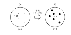
実施例の説明に先立って、菌の検査の概略について説明する。飲食店や食料品メーカーでは、菌の量の検査が行われている。菌は小さくて直接見ることができないため、図1(a)を参照して、例えば、検査対象の食品を希釈したうえ培地上に塗り、数日間培養を行う。その結果、図1(b)を参照して、菌が増殖して目に見える大きさのコロニーが生成される。コロニーをカウントすることによって、菌の量の検査を行うことができる。しかしながら、コロニーを目視でカウントする方法は非効率である。そこで、より簡易にコロニーをカウントする技術が望まれる。 Prior to the description of the examples, an outline of the bacteria test will be described. At restaurants and food manufacturers, the amount of bacteria is inspected. Since the bacteria are small and cannot be seen directly, referring to FIG. 1 (a), for example, the food to be examined is diluted and applied onto the medium and cultured for several days. As a result, referring to FIG. 1B, bacteria grow and colonies having a visible size are generated. By counting colonies, the amount of bacteria can be examined. However, the method of counting colonies visually is inefficient. Therefore, a technique for counting colonies more easily is desired.
例えば、装置を用いてコロニーを自動で検出する方法が挙げられる。培養後の菌の画像を取得し、輪郭の形状を用いて、つながっているコロニーを分離する技術を用いることができる。この技術は、輪郭線の垂線を伸ばした場合に、それらが交わる場合にその中心の個数を求めるという手法である。しかしながら、この技術では、3つ以上のコロニーがつながっているような場合にうまく分離できないという問題がある。 For example, a method of automatically detecting colonies using an apparatus can be mentioned. A technique can be used in which an image of the cultured bacteria is acquired and the connected colonies are separated using the contour shape. This technique is a method of obtaining the number of the centers when the perpendiculars of the contour lines are extended and they intersect. However, this technique has a problem that it cannot be separated well when three or more colonies are connected.
特に黄色ブドウ球菌などの菌は、培養するとコロニーの周りが半透明に白濁するレシチナーゼ反応という現象が発生する。図2(a)は、レシチナーゼ反応を説明するための模式図である。図2(a)を参照して、レシチナーゼ反応が生じると、コロニー1の周りに半透明の白濁領域2が現れる。レシチナーゼ反応が進んで白濁領域2が広がると、複数のコロニー1間で白濁領域2が重なってしまう。この場合、輪郭線に基づいてコロニーをカウントするのは困難である。
In particular, bacteria such as Staphylococcus aureus cause a phenomenon called lecithinase reaction in which the periphery of the colony becomes translucent and cloudy when cultured. FIG. 2A is a schematic diagram for explaining the lecithinase reaction. Referring to FIG. 2A, when a lecithinase reaction occurs, a translucent
これに対して、図2(b)を参照して、黄色ブドウ球菌などのリパーゼ陽性菌あるいは、表面が円滑なS(Smooth)型の菌のコロニーでは、コロニー1に真珠様の光沢3が現れる。そこで、光沢3を検出し、光沢3をカウントすることによってコロニーをカウントすることができる。以下の実施例では、光沢に着目し、簡易にコロニーをカウントすることができるコロニーカウント装置、コロニーカウント方法、およびコロニーカウントプログラムについて説明する。
On the other hand, referring to FIG. 2B, a
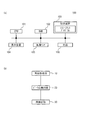
図3(a)は、実施例1に係るコロニーカウント装置100のハードウェア構成を説明するためのブロック図である。図3(a)を参照して、コロニーカウント装置100は、CPU101、RAM102、記憶装置103、表示装置104、画像センサ105、光源106等を備える。
FIG. 3A is a block diagram for explaining a hardware configuration of the
CPU(Central Processing Unit)101は、中央演算処理装置である。CPU101は、1以上のコアを含む。RAM(Random Access Memory)102は、CPU101が実行するプログラム、CPU101が処理するデータなどを一時的に記憶する揮発性メモリである。記憶装置103は、不揮発性記憶装置である。記憶装置103として、例えば、ROM(Read Only Memory)、フラッシュメモリなどのソリッド・ステート・ドライブ(SSD)、ハードディスクドライブに駆動されるハードディスクなどを用いることができる。記憶装置103は、コロニーカウントプログラムなどを記憶している。
A CPU (Central Processing Unit) 101 is a central processing unit. The
表示装置104は、液晶ディスプレイ、エレクトロルミネッセンスパネルなどであり、画像センサ105が取得した画像、コロニーのカウントの結果などを表示する。画像センサ105は、培養された菌の画像を取得できるものであれば特に限定されるものではなく、一例としてCMOS(Complementary Metal Oxide Semiconductor)カメラなどである。光源106は、培養された菌に対して光を照射する装置である。
The
なお、画像センサ105は、一例として、シャーレ上で卵黄加マンニット食塩寒天培地等の培地で培養処理を行った後の画像を取得する。シャーレの位置は、予め決められているものとする。例えば、撮影中の画像に解析範囲の円形を重畳表示して、人がおおざっぱな位置合わせを行う方法等がある。また、画像を解析して、ハフ変換などの既存手法を用いてシャーレの円形を抽出する方法等も考えられる。
As an example, the
記憶装置103に記憶されているコロニーカウントプログラムは、実行可能にRAM102に展開される。CPU101は、RAM102に展開されたコロニーカウントプログラムを実行する。それにより、コロニーカウント装置100によるコロニーカウント処理が実行される。コロニーカウント処理は、コロニーをカウントする処理である。
The colony count program stored in the
図3(b)は、コロニーカウントプログラムの実行によって実現される各機能のブロック図である。コロニーカウントプログラムの実行によって、コロニーカウント装置100には、画像取得部10、ピーク点検出部20、および菌検出部30が実現される。
FIG. 3B is a block diagram of each function realized by executing the colony count program. By executing the colony count program, the
続いて、コロニーカウント装置100の動作について説明する。図4は、コロニーカウント装置100によって実行されるフローチャートの一例を説明するための図である。図4を参照して、画像取得部10は、画像センサ105から菌の画像を取得する(ステップS1)。次に、ピーク点検出部20は、ステップS1で取得した画像から、光沢の候補として輝度ピークを検出することによって光沢を検出する(ステップS2)。次に、菌検出部30は、ステップS2で検出された光沢をカウントすることで、コロニーをカウントする(ステップS3)。以上の処理の実行によって、コロニーをカウントすることができる。
Subsequently, the operation of the
次に、光沢の検出の詳細について説明する。光沢は、周りと比べて輝度が高くなっている箇所である。そこで、本実施例では、輝度ピークを検出することによって、光沢を検出する。図5(a)〜図5(c)は、輝度ピークの検出の詳細を表す図である。図5(a)を参照して、ピーク点検出部20は、画像センサ105から取得した画像をスキャンすることによって、当該画像における輝度の分布を取得する。図5(b)は、あるコロニー1を含む領域の拡大図である。図5(c)は、図5(b)のコロニー1の光沢3の周辺の拡大図である。図5(c)を参照して、光沢3においては周囲と比較して輝度が高くなることから、輝度ピークを検出することによって光沢3を検出することができる。例えば、所定の画素(1つの画素でもよく、3×3等の複数の画素の平均としてもよい)が、その周辺の画素と比較してしきい値以上に高い場合に、当該所定の画素の部分を輝度ピークとして検出することができる。
Next, details of gloss detection will be described. Gloss is a place where the brightness is higher than the surrounding area. Therefore, in this embodiment, the gloss is detected by detecting the luminance peak. FIG. 5A to FIG. 5C are diagrams showing details of detection of a luminance peak. With reference to Fig.5 (a), the peak
まず、画像センサ105が取得した画像において、座標位置(x,y)の画素の輝度をp(x,y)とした場合、輝度P(x,y)を中心画素の輝度とする。中心画素の輝度P(x,y)として、輝度p(x,y)そのものを用いても構わないが、複数の画素の平均を用いても構わない。例えば、上下左右1ピクセル(合計9ピクセル)の平均を求める場合は、下記式(1)に従って中心画素の輝度P(x,y)を求めることができる。
次にその周辺の画素(例えば、10×10の領域内画素、中心付近を除く)の輝度がすべて、中心画素の輝度P(x,y)より低く、かつ一定距離以上離れた位置の画素値が中心画素の輝度よりしきい値以上低い場合にその部分を輝度のピークとして検出する。具体的には、下記式(2)および下記式(3)が成立する場合に、中心画素が輝度のピークとして検出される。なお、「r1」、「r2」は範囲を表わし、r1<r2の関係が成立する。また、「t」はしきい値を表す。図6は、下記式(2)および下記式(3)の範囲を表す図である。
p(a,b)≦P(x,y) a,bは(a−x)2+(b−y)2≦r12を満たす範囲。
p(c,d)≦P(x,y)−t c,dは(r12≦(x−c)2+(y−d)2≦r22を満たす範囲。
Next, the pixel values at positions where the brightness of the surrounding pixels (for example, pixels in the 10 × 10 area, excluding the vicinity of the center) are all lower than the brightness P (x, y) of the center pixel and are more than a certain distance apart. Is lower than the luminance of the central pixel by a threshold value or more, that portion is detected as a luminance peak. Specifically, when the following formula (2) and the following formula (3) are satisfied, the center pixel is detected as a luminance peak. Note that “r1” and “r2” represent ranges, and the relationship r1 <r2 is established. “T” represents a threshold value. FIG. 6 is a diagram illustrating ranges of the following formula (2) and the following formula (3).
p (a, b) ≦ P (x, y) a, b satisfies (a-x) 2 + ( b-y) 2 ≦
p (c, d) ≦ P (x, y) −t c, d is a range satisfying (r1 2 ≦ (x−c) 2 + (y−d) 2 ≦ r2 2 .
図7は、輝度ピークを検出する際に実行されるフローチャートの1例である。図7を参照して、ピーク点検出部20は、現在位置(x,y)を設定する(ステップS11)。次に、ピーク点検出部20は、現在位置の周辺の画素値の平均値を求める(ステップS12)。次に、ピーク点検出部20は、現在位置の周辺の画素で、ステップS12で求めた平均値以上の画素があるか判定する(ステップS13)。
FIG. 7 is an example of a flowchart executed when a luminance peak is detected. Referring to FIG. 7, peak
ステップS13で「No」と判定された場合、ピーク点検出部20は、現在位置の一定距離離れた位置の画素で、(ステップS12で求めた平均値−しきい値)以上の画素があるか判定する(ステップS14)。ステップS14で「No」と判定された場合、ピーク点検出部20は、現在位置(x,y)を輝度のピークとして設定する(ステップS15)。次に、ピーク点検出部20は、現在位置をx軸プラス方向(例えば右)に移動させる(ステップS16)。現在位置が既に右端であれば、y軸マイナスの列(例えば下)の左端に現在位置を移動させる。次に、ピーク点検出部20は、画像の全ての座標について輝度ピークの検出処理が終了したか否かを判定する(ステップS17)。ステップS17で「No」と判定された場合、ステップS12から再度実行される。
If “No” is determined in step S13, the peak
図5のフローチャートの実行によって、全ての座標に関して輝度ピークの検出を行うことができる。なお、ステップS13またはステップS14で「Yes」と判定された場合、ステップS17が実行される。 By executing the flowchart of FIG. 5, the luminance peak can be detected for all coordinates. If “Yes” is determined in step S13 or step S14, step S17 is executed.
本実施例によれば、取得した画像において輝度ピークを検出するだけでコロニーをカウントすることができるため、簡易にコロニーをカウントすることができる。また、レシチナーゼ反応が生じても各コロニーに光沢が現れるため、高い精度でコロニーをカウントすることができる。 According to the present embodiment, colonies can be counted simply by detecting a luminance peak in the acquired image, so that colonies can be counted easily. In addition, even if a lecithinase reaction occurs, since the gloss appears in each colony, the colonies can be counted with high accuracy.
黄色ブドウ球菌などの球菌には、真珠様の光沢が現れるが、図8を参照して、1つのコロニー1に複数の光沢3が現れる場合がある。そこで、実施例2においては、複数の光沢が現れているコロニーを検出し、重複する光沢の数を差し引くことによって、コロニーのカウント精度を向上させる。
A pearly luster appears in cocci such as Staphylococcus aureus, but a plurality of
図9は、実施例2に係るコロニーカウントプログラムの実行によって実現される各機能のブロック図である。コロニーカウントプログラムの実行によって、コロニーカウント装置100には、画像取得部10、ピーク点検出部20、菌検出部30、近接ピーク点検出部40、ピーク点方向検出部50、ピーク点方向交差検出部60、点間変化検出部70、および同一コロニー判定部80が実現される。
FIG. 9 is a block diagram of each function realized by executing the colony count program according to the second embodiment. By executing the colony count program, the
図10は、実施例2に係るコロニーカウント装置100によって実行されるフローチャートの一例を説明するための図である。図10を参照して、画像取得部10は、画像センサ105から菌の画像を取得する(ステップS21)。次に、ピーク点検出部20は、ステップS21で取得した画像から、光沢の候補として輝度ピークを検出することによって光沢を検出する(ステップS22)。次に、同一コロニー判定部80は、近接ピーク点検出部40、ピーク点方向検出部50、ピーク点方向交差検出部60および点間変化検出部70の処理結果に応じて、輝度ピークが同一コロニーにあるか否かを判定する(ステップS23)。次に、菌検出部30は、ステップS22で検出された輝度ピークの数から、ステップS23で検出された重複分を差し引くことによって、コロニーをカウントする(ステップS24)。以上の処理の実行によって、高い精度でコロニーをカウントすることができる。
FIG. 10 is a diagram for explaining an example of a flowchart executed by the
続いて、図10のステップS23の処理の詳細について説明する。ステップS23では、輝度ピークが複数検出された場合に、それらが同一のコロニーであるかどうかの判定を行う。同一のコロニーかどうかの判定は、例えば、二つの輝度ピーク間の距離および向き、ならびに画素により行うことができる。 Next, details of the process in step S23 of FIG. 10 will be described. In step S23, when a plurality of luminance peaks are detected, it is determined whether or not they are the same colony. The determination of whether or not they are the same colony can be performed by, for example, the distance and direction between two luminance peaks, and pixels.
(1)コロニーの中心方向の検出
まず、近接ピーク点検出部40は、互いの距離がしきい値以下となる複数の輝度ピークを検出する。ピーク点方向検出部50は、これらの輝度ピークから見た、コロニーの中心方向を検出する。コロニーの周りの輝度は、コロニー内の輝度より低いため、光沢周辺において輝度が低い方向から高い方向を求めることで中心方向を検出することができる。すなわち、輝度勾配を求めることによって、中心方向を検出することができる。図11(a)は、各光沢3における輝度勾配を表す図である。輝度勾配の検出方法として、以下のような方法が考えられる。まず、図11(b)を参照して、輝度ピークについて、その周辺の画素情報を取得し、上側、下側、右側、左側の指定サイズの領域について、その輝度の平均を検出する。それぞれをAu,Ad,Ar,Alとすると、輝度の勾配方向(勾配角度θ)は、下記式(4)で表すことができる。
Arは、例えば、下記式(5)に従って算出することができる。
(2)輝度のピークをつなぐ線の交差判定
ピーク点方向交差検出部60は、中心方向が交差する点を求める。この交差する点は、中心方向上の直線の交点により求めることができる。輝度ピークの位置をそれぞれ(x1,y1)、(x2,y2)とし、勾配をそれぞれa1,a2とした場合、二つの頂点の交点は、下記式(6)および下記式(7)で求めることができる。
(3)直線上の輝度変化の抽出
例えば、図12(b)のように複数の輝度ピークが同一コロニー内に現れる場合、図12(d)のように一方の輝度ピークから中心方向の交点への輝度の変化、および当該交点から他方の輝度ピークへの輝度の変化は小さくなる。これに対して、図12(c)のように輝度ピークが異なるコロニーに現れる場合、図12(e)のように一方の輝度ピークから中心方向の交点への輝度の変化、および当該交点から他方の輝度ピークへの輝度の変化は、コロニーの境界付近で大きくなる。そこで、一方の輝度ピークから中心方向の交点への輝度の変化、および当該交点から他方の輝度ピークへの輝度の変化において、所定のしきい値を超える部分が無ければ、それらの輝度ピークは同一のコロニー内に現れているものと判定することができる。
(3) Extraction of luminance change on a straight line For example, when a plurality of luminance peaks appear in the same colony as shown in FIG. 12B, from one luminance peak to the intersection in the center direction as shown in FIG. And the change in luminance from the intersection to the other luminance peak becomes small. On the other hand, when the luminance peak appears in different colonies as shown in FIG. 12C, the luminance change from one luminance peak to the intersection in the central direction as shown in FIG. The change in the luminance to the luminance peak increases in the vicinity of the colony boundary. Therefore, if there is no portion that exceeds a predetermined threshold in the change in luminance from one luminance peak to the intersection in the central direction and the change in luminance from the intersection to the other luminance peak, those luminance peaks are the same. It can be determined that it appears in the colony.
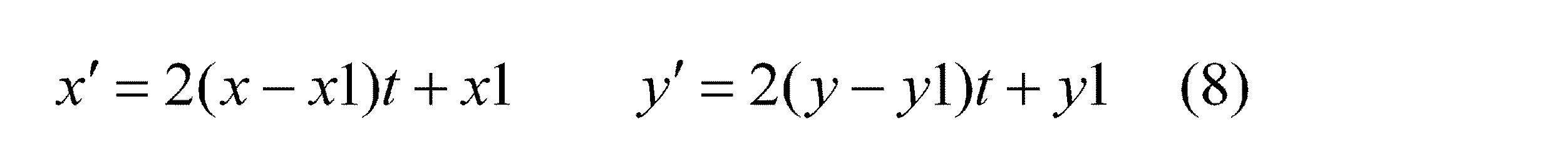
まず、点間変化検出部70は、(x1,y1)→(x,y)→(x2,y2)において、交点(x,y)で折れ曲がっている直線を算出する。座標位置を下記式(8)および下記式(9)で表した場合の輝度変化を求める。なお、tは0≦t≦1の範囲の値を持つ媒介変数であり、下記式(8)は0≦t≦0.5の範囲でtが0→0.5まで変化した場合に座標値が(x1,y1)→(x,y)まで変動する際の座標値(x´,y´)を求める場合の式であり、下記式(9)は0.5≦t≦1の範囲でtが0.5→1まで変化した場合に座標値が(x1,y1)→(x,y)まで変動する際の座標値(x´,y´)を求める場合の式である。
この場合、輝度ピークをつなぐ線の輝度の関数は、下記式(10)のように表すことができる。なお、下記式(10)において、tは、0≦t≦1である。また、v(t)は位置tにおける輝度値である。この場合、下記式(11)に従って、輝度の分散を求めることができる。このvバーはv(t)の平均値である。式(11)は積分を用いているが、式(12)のように離散的な値の和として分散を計算しても構わない。ここで、mは計算する点の個数であり、10など固定の値を指定する。この分散の値があらかじめ決められたしきい値より小さい場合、同一のコロニー上にあると判定することができる。
同一コロニーにあるかどうかの判定は、条件によってはより簡略化した方法を用いることも考えられる。たとえば、(3)の輝度変化の条件を使わずに(2)のの処理までで判定することも考えられる。また(1)(2)の処理を使用せずに、二つの輝度のピークをつないだ直線上の(3)の輝度変化を用いることも考えられる。 It may be possible to determine whether or not they are in the same colony by using a simplified method depending on conditions. For example, it is conceivable that the determination is made up to the processing of (2) without using the luminance change condition of (3). It is also conceivable to use the luminance change (3) on a straight line connecting two luminance peaks without using the processes (1) and (2).
図13は、輝度ピークが同一コロニーにあるか否かを検出する際に実行されるフローチャートの1例である。図13を参照して、近接ピーク点検出部40は、距離が近い(しきい値以下の)輝度ピークを2つ選択する(ステップS31)。次に、ピーク点方向検出部50は、各輝度ピークの上下左右の画素の輝度平均を求め、輝度勾配(中心方向)を求める(ステップS32)。
FIG. 13 is an example of a flowchart executed when detecting whether or not the luminance peak is in the same colony. Referring to FIG. 13, the proximity peak
次に、ピーク点方向交差検出部60は、2つの輝度勾配の交点を求め、それぞれの距離を求める(ステップS33)。点間変化検出部70は、交点が2つの輝度のピークに対してしきい値以上離れているか否かを判定する(ステップS34)。ステップS34で「No」と判定された場合、点間変化検出部70は、交線上の輝度変化を求める(ステップS35)。
Next, the peak point direction intersection detection unit 60 obtains the intersections of the two luminance gradients, and obtains the respective distances (step S33). The point-to-point
次に、同一コロニー判定部80は、輝度変化がしきい値以下であるか否かを判定する(ステップS36)。ステップS36で「Yes」と判定された場合、同一コロニー判定部80は、2つの輝度のピークは同一コロニーにあると判定する(ステップS37)。ステップS36で「No」と判定された場合、同一コロニー判定部80は、2つの輝度のピークは同一コロニーにないと判定する(ステップS38)。ステップS34で「Yes」と判定された場合、ステップS38が実行される。ステップS37またはステップS38の実行後、同一コロニー判定部80は、全ての輝度ピークを判定したか否かを判定する(ステップS39)。ステップS39で「No」と判定された場合、ステップS31が再度実行される。ステップS39で「Yes」と判定された場合、フローチャートの実行が終了する。
Next, the same
本実施例によれば、同一コロニー内に複数の光沢が現れる場合に、重複分をカウントから除外することができる。それにより、コロニーのカウント精度が向上する。具体的には、互いの距離がしきい値以下の2つの輝度ピークから中心方向に直線を引いた場合に、当該直線の交点と2つの輝度ピークとの距離がしきい値以下であれば、当該2つの輝度ピークは同一コロニー内にあると判定する。この場合、コロニーのカウント精度が向上する。また、当該2つの輝度ピークと当該交点とを結ぶ直線において、輝度変化が大きい場合に、当該2つの輝度ピークが異なるコロニー内にあると判定し、輝度変化が小さい場合に、当該2つの輝度ピークは同一コロニー内にあると判定する。この場合にも、コロニーのカウント精度が向上する。 According to the present embodiment, when a plurality of glosses appear in the same colony, the overlap can be excluded from the count. Thereby, colony counting accuracy is improved. Specifically, when a straight line is drawn in the center direction from two luminance peaks whose distance is less than or equal to the threshold value, if the distance between the intersection of the straight line and the two luminance peaks is equal to or less than the threshold value, It is determined that the two luminance peaks are in the same colony. In this case, the colony counting accuracy is improved. Further, in a straight line connecting the two luminance peaks and the intersection, when the luminance change is large, it is determined that the two luminance peaks are in different colonies, and when the luminance change is small, the two luminance peaks Are determined to be in the same colony. Also in this case, the colony counting accuracy is improved.
なお、コロニーカウントプログラムの実行によって実現される各部は、専用の回路などによって構成されていてもよい。 In addition, each part implement | achieved by execution of a colony count program may be comprised by the circuit for exclusive use.
実施例1においては、菌検出部30が、コロニーをカウントするカウント部として機能する。実施例2においては、近接ピーク点検出部40、ピーク点方向検出部50、ピーク点方向交差検出部60、点間変化検出部70、同一コロニー判定部80および菌検出部30が、コロニーをカウントするカウント部として機能する。
In Example 1, the
以上、本発明の実施例について詳述したが、本発明は係る特定の実施例に限定されるものではなく、特許請求の範囲に記載された本発明の要旨の範囲内において、種々の変形・変更が可能である。 Although the embodiments of the present invention have been described in detail above, the present invention is not limited to such specific embodiments, and various modifications and changes can be made within the scope of the gist of the present invention described in the claims. It can be changed.
10 画像取得部
20 ピーク点検出部
30 菌検出部
40 近接ピーク点検出部
50 ピーク点方向検出部
60 ピーク点方向交差検出部
70 点間変化検出部
80 同一コロニー判定部
100 コロニーカウント装置
DESCRIPTION OF
Claims (5)
前記菌の画像において、輝度ピークを検出するピーク検出部と、
前記ピーク検出部が検出した輝度ピークの数に基づいてコロニーをカウントするカウント部と、を備え、
前記カウント部は、複数の輝度ピークの周辺の輝度分布から各輝度ピーク周辺の輝度勾配を算出し、当該輝度勾配において輝度値の低い方から輝度値の高い方に直線を引いた場合に各輝度ピークから当該直線の交点までに輝度値の変化が所定のしきい値を超える部分をまたぐか否かを判定し、またがないと判定した場合に、当該複数の輝度ピークを1つの輝度ピークとしてカウントすることを特徴とするコロニーカウント装置。 An image acquisition unit for acquiring an image of the cultured bacteria;
In the image of the fungus, a peak detection unit that detects a luminance peak;
A counting unit that counts colonies based on the number of luminance peaks detected by the peak detection unit , and
The counting unit calculates a luminance gradient around each luminance peak from a luminance distribution around a plurality of luminance peaks, and draws a straight line from a lower luminance value to a higher luminance value in the luminance gradient. It is determined whether or not the change in luminance value exceeds a predetermined threshold value from the peak to the intersection of the straight line, and when it is determined that it does not extend, the plurality of luminance peaks are regarded as one luminance peak. colonies count and wherein the counting.
前記菌の画像において、輝度ピークを検出し、
検出された輝度ピークの数に基づいてコロニーをカウントし、
前記カウントの際に、複数の輝度ピークの周辺の輝度分布から各輝度ピーク周辺の輝度勾配を算出し、当該輝度勾配において輝度値の低い方から輝度値の高い方に直線を引いた場合に各輝度ピークから当該直線の交点までに輝度値の変化が所定のしきい値を超える部分をまたぐか否かを判定し、またがないと判定した場合に、当該複数の輝度ピークを1つの輝度ピークとしてカウントすることを特徴とするコロニーカウント方法。 Obtain an image of the cultured bacteria,
In the image of the fungus, a luminance peak is detected,
Count colonies based on the number of detected luminance peaks ,
At the time of counting, the brightness gradient around each brightness peak is calculated from the brightness distribution around the plurality of brightness peaks, and when a straight line is drawn from the lower brightness value to the higher brightness value in the brightness gradient, It is determined whether or not the change of the luminance value exceeds a predetermined threshold value from the luminance peak to the intersection of the straight line, and when it is determined that it does not extend, the plurality of luminance peaks are regarded as one luminance peak. Counting as a colony counting method.
培養された菌の画像を取得するステップと、
前記菌の画像において、輝度ピークを検出するステップと、
検出された輝度ピークの数に基づいてコロニーをカウントするステップと、を実行させ、
前記カウントするステップにおいて、複数の輝度ピークの周辺の輝度分布から各輝度ピーク周辺の輝度勾配を算出し、当該輝度勾配において輝度値の低い方から輝度値の高い方に直線を引いた場合に各輝度ピークから当該直線の交点までに輝度値の変化が所定のしきい値を超える部分をまたぐか否かを判定し、またがないと判定した場合に、当該複数の輝度ピークを1つの輝度ピークとしてカウントすることを特徴とするコロニーカウントプログラム。 On the computer,
Obtaining an image of the cultured bacteria;
Detecting a luminance peak in the bacteria image;
Counting colonies based on the number of detected luminance peaks , and
In the counting step, a luminance gradient around each luminance peak is calculated from a luminance distribution around a plurality of luminance peaks, and each line is drawn when a straight line is drawn from a lower luminance value to a higher luminance value in the luminance gradient. It is determined whether or not the change of the luminance value exceeds a predetermined threshold value from the luminance peak to the intersection of the straight line, and when it is determined that it does not extend, the plurality of luminance peaks are regarded as one luminance peak. colonies count program characterized by counting as.
Priority Applications (1)
| Application Number | Priority Date | Filing Date | Title |
|---|---|---|---|
| JP2013163602A JP6229365B2 (en) | 2013-08-06 | 2013-08-06 | Colony counting device, colony counting method, and colony counting program |
Applications Claiming Priority (1)
| Application Number | Priority Date | Filing Date | Title |
|---|---|---|---|
| JP2013163602A JP6229365B2 (en) | 2013-08-06 | 2013-08-06 | Colony counting device, colony counting method, and colony counting program |
Publications (2)
| Publication Number | Publication Date |
|---|---|
| JP2015029504A JP2015029504A (en) | 2015-02-16 |
| JP6229365B2 true JP6229365B2 (en) | 2017-11-15 |
Family
ID=52515375
Family Applications (1)
| Application Number | Title | Priority Date | Filing Date |
|---|---|---|---|
| JP2013163602A Active JP6229365B2 (en) | 2013-08-06 | 2013-08-06 | Colony counting device, colony counting method, and colony counting program |
Country Status (1)
| Country | Link |
|---|---|
| JP (1) | JP6229365B2 (en) |
Families Citing this family (6)
| Publication number | Priority date | Publication date | Assignee | Title |
|---|---|---|---|---|
| JP2016123407A (en) * | 2014-12-26 | 2016-07-11 | 富士通株式会社 | Image processing apparatus, image processing method, and image processing program |
| JP2016158577A (en) * | 2015-03-03 | 2016-09-05 | 富士フイルム株式会社 | Cell colony detection device, cell colony detection method, and program |
| EP3115929A1 (en) * | 2015-07-06 | 2017-01-11 | Fujitsu Limited | Image apparatus, image processing method and image processing program |
| JP2019058074A (en) | 2017-09-25 | 2019-04-18 | オリンパス株式会社 | Image processing apparatus, cell cluster recognition apparatus, cell cluster recognition method, and cell cluster recognition program |
| JP6832970B2 (en) * | 2019-02-27 | 2021-02-24 | 富士フイルム株式会社 | Cell colony detectors and methods and programs |
| FR3109159B1 (en) * | 2020-04-09 | 2023-06-23 | Interscience | Image processing method applied to colony counters in microbiology |
Family Cites Families (1)
| Publication number | Priority date | Publication date | Assignee | Title |
|---|---|---|---|---|
| CA2322072A1 (en) * | 1998-12-28 | 2000-07-06 | Sapporo Breweries Ltd. | Method of apparatus for enumerating microbes by counting luminous points on a digitized pixilated image |
-
2013
- 2013-08-06 JP JP2013163602A patent/JP6229365B2/en active Active
Also Published As
| Publication number | Publication date |
|---|---|
| JP2015029504A (en) | 2015-02-16 |
Similar Documents
| Publication | Publication Date | Title |
|---|---|---|
| JP6229365B2 (en) | Colony counting device, colony counting method, and colony counting program | |
| JP5742399B2 (en) | Image processing apparatus and program | |
| US9117281B2 (en) | Surface segmentation from RGB and depth images | |
| JP5765026B2 (en) | Image processing apparatus and program | |
| JP5801237B2 (en) | Part estimation apparatus, part estimation method, and part estimation program | |
| JP2018525746A5 (en) | ||
| JP6317725B2 (en) | System and method for determining clutter in acquired images | |
| KR102073468B1 (en) | System and method for scoring color candidate poses against a color image in a vision system | |
| EP2980755A1 (en) | Method for partitioning area, and inspection device | |
| JP2018181333A5 (en) | ||
| US20120207379A1 (en) | Image Inspection Apparatus, Image Inspection Method, And Computer Program | |
| US10304202B2 (en) | Evaluation device for skin texture based on skin blob and method thereof | |
| CN110832542B (en) | Identification processing device, identification processing method, and program | |
| US20150227789A1 (en) | Information processing apparatus, information processing method, and program | |
| JP2012115342A5 (en) | ||
| JP5780791B2 (en) | Cell tracking method | |
| JP2015082287A (en) | Image processing apparatus, image processing method, and image processing program | |
| JP5259348B2 (en) | Height information acquisition device, height information acquisition method, and program | |
| WO2019181072A1 (en) | Image processing method, computer program, and recording medium | |
| JP2019091308A (en) | Object detector, image analysis device, object analytical method, image analysis method, program, and learning data | |
| WO2005057496A1 (en) | Method and device for detecting an object from image | |
| WO2017056600A1 (en) | Image processing method and control program | |
| CN117351011B (en) | Screen defect detection method, apparatus, and readable storage medium | |
| JP2013168081A (en) | Edge detection device and edge detection method | |
| JP6951853B2 (en) | Analysis result viewing device |
Legal Events
| Date | Code | Title | Description |
|---|---|---|---|
| A621 | Written request for application examination |
Free format text: JAPANESE INTERMEDIATE CODE: A621 Effective date: 20160510 |
|
| A977 | Report on retrieval |
Free format text: JAPANESE INTERMEDIATE CODE: A971007 Effective date: 20170127 |
|
| A131 | Notification of reasons for refusal |
Free format text: JAPANESE INTERMEDIATE CODE: A131 Effective date: 20170207 |
|
| A521 | Written amendment |
Free format text: JAPANESE INTERMEDIATE CODE: A523 Effective date: 20170407 |
|
| TRDD | Decision of grant or rejection written | ||
| A01 | Written decision to grant a patent or to grant a registration (utility model) |
Free format text: JAPANESE INTERMEDIATE CODE: A01 Effective date: 20170919 |
|
| A61 | First payment of annual fees (during grant procedure) |
Free format text: JAPANESE INTERMEDIATE CODE: A61 Effective date: 20171002 |
|
| R150 | Certificate of patent or registration of utility model |
Ref document number: 6229365 Country of ref document: JP Free format text: JAPANESE INTERMEDIATE CODE: R150 |