JP6227002B2 - Two-stage ignition type inflator - Google Patents
Two-stage ignition type inflator Download PDFInfo
- Publication number
- JP6227002B2 JP6227002B2 JP2015545062A JP2015545062A JP6227002B2 JP 6227002 B2 JP6227002 B2 JP 6227002B2 JP 2015545062 A JP2015545062 A JP 2015545062A JP 2015545062 A JP2015545062 A JP 2015545062A JP 6227002 B2 JP6227002 B2 JP 6227002B2
- Authority
- JP
- Japan
- Prior art keywords
- igniter
- stage
- ignition
- assembly
- inflector
- Prior art date
- Legal status (The legal status is an assumption and is not a legal conclusion. Google has not performed a legal analysis and makes no representation as to the accuracy of the status listed.)
- Active
Links
Images


Classifications
-
- B—PERFORMING OPERATIONS; TRANSPORTING
- B60—VEHICLES IN GENERAL
- B60R—VEHICLES, VEHICLE FITTINGS, OR VEHICLE PARTS, NOT OTHERWISE PROVIDED FOR
- B60R21/00—Arrangements or fittings on vehicles for protecting or preventing injuries to occupants or pedestrians in case of accidents or other traffic risks
- B60R21/02—Occupant safety arrangements or fittings, e.g. crash pads
- B60R21/16—Inflatable occupant restraints or confinements designed to inflate upon impact or impending impact, e.g. air bags
- B60R21/26—Inflatable occupant restraints or confinements designed to inflate upon impact or impending impact, e.g. air bags characterised by the inflation fluid source or means to control inflation fluid flow
- B60R21/264—Inflatable occupant restraints or confinements designed to inflate upon impact or impending impact, e.g. air bags characterised by the inflation fluid source or means to control inflation fluid flow using instantaneous generation of gas, e.g. pyrotechnic
- B60R21/2644—Inflatable occupant restraints or confinements designed to inflate upon impact or impending impact, e.g. air bags characterised by the inflation fluid source or means to control inflation fluid flow using instantaneous generation of gas, e.g. pyrotechnic using only solid reacting substances, e.g. pellets, powder
-
- B—PERFORMING OPERATIONS; TRANSPORTING
- B60—VEHICLES IN GENERAL
- B60R—VEHICLES, VEHICLE FITTINGS, OR VEHICLE PARTS, NOT OTHERWISE PROVIDED FOR
- B60R21/00—Arrangements or fittings on vehicles for protecting or preventing injuries to occupants or pedestrians in case of accidents or other traffic risks
- B60R21/02—Occupant safety arrangements or fittings, e.g. crash pads
- B60R21/16—Inflatable occupant restraints or confinements designed to inflate upon impact or impending impact, e.g. air bags
- B60R21/26—Inflatable occupant restraints or confinements designed to inflate upon impact or impending impact, e.g. air bags characterised by the inflation fluid source or means to control inflation fluid flow
- B60R2021/26029—Ignitors
-
- B—PERFORMING OPERATIONS; TRANSPORTING
- B60—VEHICLES IN GENERAL
- B60R—VEHICLES, VEHICLE FITTINGS, OR VEHICLE PARTS, NOT OTHERWISE PROVIDED FOR
- B60R21/00—Arrangements or fittings on vehicles for protecting or preventing injuries to occupants or pedestrians in case of accidents or other traffic risks
- B60R21/02—Occupant safety arrangements or fittings, e.g. crash pads
- B60R21/16—Inflatable occupant restraints or confinements designed to inflate upon impact or impending impact, e.g. air bags
- B60R21/26—Inflatable occupant restraints or confinements designed to inflate upon impact or impending impact, e.g. air bags characterised by the inflation fluid source or means to control inflation fluid flow
- B60R21/264—Inflatable occupant restraints or confinements designed to inflate upon impact or impending impact, e.g. air bags characterised by the inflation fluid source or means to control inflation fluid flow using instantaneous generation of gas, e.g. pyrotechnic
- B60R21/2644—Inflatable occupant restraints or confinements designed to inflate upon impact or impending impact, e.g. air bags characterised by the inflation fluid source or means to control inflation fluid flow using instantaneous generation of gas, e.g. pyrotechnic using only solid reacting substances, e.g. pellets, powder
- B60R2021/2648—Inflatable occupant restraints or confinements designed to inflate upon impact or impending impact, e.g. air bags characterised by the inflation fluid source or means to control inflation fluid flow using instantaneous generation of gas, e.g. pyrotechnic using only solid reacting substances, e.g. pellets, powder comprising a plurality of combustion chambers or sub-chambers
Description
本発明は、一般に、自動車の乗員を衝撃から保護するために使用されるものなど、膨張式拘束エアバッグクッションを膨張させるのに使用するインフレ−タに関する。より詳細には、本発明は、複数の点火器を有しまたは包含するインフレ−タに関し、より具体的には、二段点火式インフレ−タに関する。
The present invention relates generally to inflators used to inflate inflatable restraint airbag cushions, such as those used to protect automobile occupants from impact. More particularly, the present invention relates to an inflector having or including a plurality of igniters, and more particularly to a two-stage ignition type inflector.
車両が衝突時など、突然の減速に遭遇したとき、ガスによって膨張または拡張される、たとえば「エアバッグ」などのクッションまたはバッグを使用して、車両の乗員を保護することは周知である。そのようなシステムでは、エアバッグクッションは、通常、必要なスペースを最小限に抑えるために、膨張させずに折り畳まれた状態で収納されている。システムの起動に際し、クッションは、一般に「インフレ−タ」と呼ばれるデバイスによって生成または供給されるガスによって、数ミリ秒にも満たないうちに膨張を開始する。 It is well known to protect a vehicle occupant using a cushion or bag, such as an “airbag”, that is inflated or expanded by gas when the vehicle encounters sudden deceleration, such as during a collision. In such systems, the airbag cushion is typically stored in a folded state without inflating to minimize the required space. Upon system start-up, the cushion begins to expand in less than a few milliseconds with gas generated or supplied by a device commonly referred to as an “inflator”.
膨張式拘束システムに使用されるものなど、エアバッグの膨張に関して、当技術分野では、様々なタイプのインフレ−タデバイスが開示されている。既知のインフレ−タデバイスの一タイプは、点火するとエアバッグを膨張させるのに十分な量のガスを生成する、燃焼性火工ガス生成物質から膨張ガスを発生させる。 Various types of inflator devices have been disclosed in the art for inflating airbags, such as those used in inflatable restraint systems. One type of known inflator device generates inflation gas from a combustible pyrotechnic gas generant that, when ignited, produces a sufficient amount of gas to inflate the airbag.
膨張式安全拘束装置は、通常、衝突時に車両乗員を拘束するエアバッグクッションを膨張させる、膨張ガスを生成するインフレ−タデバイスを用いる。その種のインフレ−タデバイスは、しばしば、インフレ−タデバイスハウジング内に貯蔵されたガス生成物質と、ハウジングと組み合わされてガス生成物質を起動させる点火器とを備える。点火器は、通常、電気コネクタと組み合わされた反応装薬を備える。電気コネクタを通って送られた信号が、反応装薬を起動させ、その反応装薬が、ガス生成物質を起動させる反応生成物を生成する。 Inflatable safety restraints typically use an inflator device that generates inflation gas that inflates an airbag cushion that restrains a vehicle occupant in the event of a collision. That kind of inflation - data devices are often inflation - comprises a motor device housing gas generating material stored in the, a igniter for activating the gas generating material is combined with the housing. The igniter typically comprises a reactive charge combined with an electrical connector. A signal sent through the electrical connector activates the reaction charge, which generates a reaction product that activates the gas generant.
変化する可能性のある作動条件、および言い換えれば、変化する可能性のある所望の性能特性の観点から、膨張式安全拘束技術は、「適応型」または「スマート」インフレ−タデバイスと呼ばれているもの、およびそれに対応する膨張式拘束システムを開発するに至っている。適応型インフレ−タデバイスでは、たとえば膨張ガスの量、供給状態、供給速度などの、1つまたは複数の出力パラメータを、たとえば環境温度、乗員の存在状態、シートベルトの使用状態、自動車の減速率などの、1つまたは複数の選択された作動条件に応じて、選択的かつ適切に変化させることができる。 In view of operating conditions that may change, and in other words, desired performance characteristics that may change, inflatable safety restraint technology is referred to as an “adaptive” or “smart” inflector device. And the corresponding inflatable restraint system has been developed. In an adaptive inflator device, one or more output parameters, such as, for example, the amount of inflation gas, supply status, supply speed, etc., for example, environmental temperature, occupant presence, seat belt usage, vehicle deceleration rate, etc. Can be selectively and appropriately varied depending on one or more selected operating conditions.
火工インフレ−タは、通常、ガス発生剤が入った1つまたは複数のチャンバを有し得る。2つのチャンバ内にガス生成物質を有し、その2つのチャンバが、それぞれの点火器または点火装置によって、独立に点火される適応型火工インフレ−タは「2段式」インフレ−タと呼ばれている。実際には、ガス生成物質を入れたそれら各ガスチャンバは、その中に入っているガス生成物質が、燃焼またはその他の方法で反応させられて、連携する膨張式拘束エアバッグクッションを膨張させるのに使用することができるような、ガスを生成または形成するので、しばしば「燃焼チャンバ」と呼ばれる。
Pyrotechnic inflation - motor may generally have one or more chambers containing the gas generating agent. An adaptive pyrotechnic inflector having gas generants in two chambers, the two chambers being independently ignited by respective igniters or igniters, is called a “two-stage” inflector It is. In practice, each of these gas chambers containing gas generants can cause the gas generants contained therein to react or otherwise react to inflate the associated inflatable restraint airbag cushion. Often referred to as a “combustion chamber” because it produces or forms a gas that can be used for
2段式インフレ−タは、いくつかの熟考された起動または着火シナリオを有し得る。第1のシナリオでは、第1または1次チャンバ内のガス生成物質および関連する起爆デバイスのみが起動され、それによって、所定の量の膨張ガスが生成される。第2の可能なシナリオでは、第1または1次点火器が最初に起動され、それによって、第1のチャンバ内のガス生成物質が最初に反応して膨張ガスを生成または形成し、予め決定または選択された遅れ時間後に、2次点火器が起動され、それによって、第2のチャンバ内のガス生成物質が反応して、さらに膨張ガスを生成または形成する。第3の可能なシナリオでは、1次点火器と2次点火器とが共に起動され、それによって、第1のチャンバ内のガス生成物質と、第2のチャンバ内のガス生成物質とが同時に起動されて、それぞれのチャンバ内のガス生成物質から膨張ガスが生成または形成される。 A two-stage inflector can have several conceived start-up or ignition scenarios. In the first scenario, only the gas generant and associated detonation device in the first or primary chamber are activated, thereby producing a predetermined amount of inflation gas. In a second possible scenario, the first or primary igniter is first activated so that the gas generant in the first chamber reacts first to generate or form an expanding gas, which is predetermined or after the selected delay time, secondary igniter is started, whereby the gas generant in the second chamber are reacted further to produce or form inflation gas. In a third possible scenario, 1 is started next mark firearms and secondary igniter are both, whereby the gas generant in the first chamber, a gas generant in the second chamber is simultaneously started Thus, an inflation gas is generated or formed from the gas generant in each chamber.
理解されるように、そのような適切な起動または着火シナリオを選択または使用することによって、たとえば膨張ガスの量、供給状態、供給速度などの、1つまたは複数のインフレ−タ出力パラメータを、たとえば環境温度、乗員の存在状態、シートベルトの使用状態、自動車の減速率などの、1つまたは複数の選択された作動条件に応じて、選択的かつ適切に変化させることができる。 As will be appreciated, by selecting or using such an appropriate start-up or ignition scenario, one or more inflector output parameters, such as, for example, the amount of inflation gas, supply conditions, supply speed, etc. Depending on one or more selected operating conditions, such as ambient temperature, occupant presence, seat belt usage, vehicle deceleration, etc., it can be varied selectively and appropriately.
従来の適応型または2段式インフレ−タデバイスは、2011年5月31日にJackson等に発行された米国特許第7,950,693号、2009年10月6日にSmith等に発行された米国特許第7,597,353号、2008年3月25日にSmith等に発行された米国特許第7,347,448号、2001年2月20日にMossi等に発行された米国特許第6,189,927号、および2000年3月7日にMossi等に発行された米国特許第6,032,979号に記載されかつ/または特許請求されたようなインフレ−タデバイスを含み、それらそれぞれの開示は、ここに参照によって本明細書に組み込まれ、本明細書に明示されるかも知れないあらゆる部分を、それらに限定されずに併せて本明細書の一部をなすものである。 Conventional adaptive or two-stage inflector devices were issued to US Pat. No. 7,950,693 issued to Jackson et al. On May 31, 2011, and issued to Smith et al. On October 6, 2009. US Pat. No. 7,597,353, US Pat. No. 7,347,448 issued to Smith et al. On March 25, 2008, US Pat. No. 6 issued to Mossi et al. On February 20, 2001 , 189,927, and U.S. Pat. No. 6,032,979 issued to Mossi et al. On March 7, 2000, each of which includes an inflator device as described and / or claimed. The disclosure of which is hereby incorporated by reference herein and is intended to include, without limitation, any part that may be expressly set forth herein. It is those that form.
最新の自動車用エアバッグ技術は、インストルメントパネル(IP)の統合性および不適正位置(OOP)の乗員に関する必要性能要件を達成するために、通常2段式インフレ−タ(スマートインフレ−タ)を採用する。この技術に固有なのが、現在の自動車市場では望ましくないいくつかの特徴である。たとえば、その種の用途に関するインフレ−タデバイスおよび関連構成ハードウェアが、最適として望まれるより、大きな寸法および重量のものになる。また、その種のインフレ−タデバイスは、しばしば、設計の複雑さの増加、ならびに構成要素の追加、および関連する製造プロセスによるコストの増加の難点を生じる。 State-of-the-art automotive airbag technology is typically two-stage inflators (smart inflators) to achieve the required performance requirements for instrument panel (IP) integrity and improper position (OOP) occupants Is adopted. Inherent in this technology are several features that are undesirable in the current automotive market. For example, the inflector device and associated component hardware for such applications will be of greater size and weight than is optimally desired. Also, such inflator devices often suffer from increased design complexity and increased costs due to the addition of components and associated manufacturing processes.
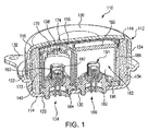
参考のために、全体を参照番号110によって示され、静的状態または状況たとえば起動前の状態で示された、現在設計されている2段式インフレ−タアセンブリを図1に示す。
For reference, a currently designed two-stage inflector assembly, shown generally by
インフレ−タアセンブリ110は、全体的に円筒状外形を有し、2つの構造部品、すなわち下方外殻または基底部分114と、上方外殻または拡散キャップ部分116とから形成されるものなどの、ハウジング構造112を備える。拡散キャップ部分116は、全体が逆さの鉢の形であり、上壁120と、円筒形側壁122とを備え、円筒形側壁122は離隔配置、好ましくはほぼ一様に離隔配置された複数のガス出口ポート124を備える。
The
基底部分114は、参照番号126および130でそれぞれ示された第1の装着開口および第2の装着開口を備える。基底部分114は、また、ハウジング112から半径方向外方へ張り出し、インフレ−タアセンブリ110を車両に取り付けるのに使用される、インターフェース取付部をなすように働くことができる周縁ブラケット132を備える。
ハウジング112は、中心的な第1のチャンバ134を画成するように構成されている。第1のチャンバ134は、図示および理解を容易にするためここでは示されていないが、通常は火工品の形態のような第1のガス生成物質の一供給量を収容または格納している。
The
第1のチャンバ134内で、そこに入っている第1のガス生成物質を取り囲む関係にあるのは、フィルタアセンブリ140である。そのようなフィルタアセンブリは、多重層または多重巻の金属スクリーンや、フィルタダンパパッドなどから形成されるものなど、1つまたは複数の燃焼スクリーンまたはフィルタを備え得る。
Within the
インフレ−タアセンブリ110は、また、インフレ−タアセンブリの部品を適正な相対配置に保持し、アセンブリを通る望ましくない流れを防止するのに適切な構造として働くことができる固定器具144を備える。
The
全体を参照番号154によって示される第1の点火装置アセンブリが、第1のチャンバ134内に、第1の装着開口126を介してハウジング112に装着されている。第1の点火装置センブリ154は、当技術分野で知られているように、点火装置または点火ブースタカップ156を備えるものなど、既知の火工起爆デバイスの形態をとることができ、その点火ブースタカップ156には、図示および理解を容易にするためにここでは示されていないが、点火物質を入れる缶158が格納されている。第1の点火装置アセンブリは、また、起爆火工出力組成物(図示せず)と連携する第1の点火デバイスまたは点火装置162と、金属などから製作される発火出力組成物収容カップおよび電気絶縁スリーブ163と、点火装置アセンブリ154が、それによってハウジング112に装着または結合される、点火装置アダプタまたは保持具164とを備える。図示のように、点火装置カップ156は、キャップ170および円筒形側壁172により、全体的に凹形の部材の形態をとり、内室174を形成することができる。点火装置カップ156は、金属などのガス不透過性材料から形成することができ、円筒形側壁172を備えており、円筒形側壁172は、離隔配置された複数のガス出口オリフィス(図示せず)を備え、そのガス出口オリフィスは、通常(たとえばインフレ−タが静的または起動前の状態のとき)、当技術分野では周知の裏面粘着箔シールラップなどを用いるなど、圧力感応式遮蔽物またはバリヤ(図示せず)を用いて覆われており、物質がそこを通るのが防止されている。既知のように、そのような遮蔽物は、それに対して点火装置カップ156の内部から所定の圧力が加わると、開口または裂開するように選択することができる。
The first igniter assembly indicated generally by
起動されると点火装置162が放電し、またはその他の方法で点火物質の缶158を裂開または開放させ、通常入っている点火物質に点火し、続いて、第1のチャンバ134に入れられたガス生成物質に点火する。
When activated, the
実際には、点火装置アセンブリ154は、保持具164を基底部分114に装着開口126において溶接することなどによって、ハウジング112に連結または接合される。
In practice, the
第1のチャンバ134は、第2のチャンバ182を格納または収容する。第2のチャンバ182は、発生剤カップ184と、閉鎖蓋185と、起爆発火出力組成物(図示せず)と連携する第2の点火デバイスまたは点火装置190と、たとえば金属製の発火出力組成物収容カップおよび電気絶縁スリーブ191と、第2の点火デバイス190および関連する第2のチャンバ182がそれによって、第2の装着開口130を介するなどして、ハウジング112に装着または結合される第2の点火装置アダプタまたは保持具192とを備える。
The
発生剤カップ184と閉鎖蓋185とは、協働して発生剤カップ内室196を形成し、その中には、ここでは図示および理解を容易にするために示されていないが、上記のように通常は火工品の形態のような、選択された量の第2のガス生成物質が望ましくは配置される。第2のガス生成物質は、通常、火工物質の形態でもよく、第1のガス生成物質と比較して、組成、形状、大きさ、または形態が同じでも異なっていてもよい。
The
発生剤カップ184と閉鎖蓋185とは、さらに望ましくは協働して、第2のチャンバ182に入っているガス生成物質の反応によって形成された燃焼生成物が、適切かつ望ましく起動されたとき、第2のチャンバ182から出て第1のチャンバ134に入り、フィルタアセンブリ140を通り、出口ポート124を通ってインフレ−タアセンブリ110から出て、連携するエアバッグクッション(図示せず)に入ることができるように働く。
The
理解されるように、作動および設計をより単純化し、信頼度を向上させた改良されたインフレ−タデバイス、およびその部品ならびに関連する製造および作動方法が必要とされ要求される。特に、より安価かつ/または、より効果的な様式(たとえば、寸法、重量、ならびに/または製造および/もしくは作動の複雑さの1つまたは複数の低減)で、特に望ましい膨張性能シナリオを提供し、そのような結果を生むインフレ−タデバイス、とりわけ複数の着火点火器を有するインフレ−タデバイス、およびその部品ならびに関連する製造および作動方法が必要とされ要求される。 As will be appreciated, there is a need and need for an improved inflector device that is simpler to operate and design and has increased reliability, and its components and associated manufacturing and operation methods. Provide particularly desirable expansion performance scenarios in a cheaper and / or more effective manner (eg one or more reductions in size, weight and / or manufacturing and / or operational complexity), An inflator device that produces such results, particularly an inflator device having multiple ignition igniters , and its components and associated manufacturing and operating methods are needed and required.
本発明は、改良されたインフレ−タデバイスの設計および構成部品を提供する。 The present invention provides improved inflector device designs and components.
一態様によれば、二段点火式インフレ−タ用の構造部品が提供される。その部品は、二段点火式起爆アセンブリを包有するモールド成形された要素を備える。二段点火式起爆アセンブリは、1次発火出力組成物と作動上連携する1次点火器、および2次発火出力組成物と作動上連携する2次点火器を備える。部品は、1次点火器および2次点火器と電気作動上連携する単一のコネクタをさらに備える。 According to one aspect, a structural component for a two-stage ignition inflector is provided. The part comprises a molded element containing a two-stage ignition detonation assembly. Two-stage ignition initiator assembly comprises a primary ignition output composition and operationally cooperate to primary point firearms, and secondary ignition output composition and operationally cooperate to secondary igniter. Component further comprises a single connector that primary point firearms and secondary igniter and the electrically operated linkage.
さらに特有な特定の実施形態によれば、部品は、たとえば、以下の項目の1つまたは複数をさらに備え、含み、もしくは形成する。すなわち、
2または3ピンコネクタ、
インフレ−タデバイスの壁と一体に成形されること、
1次発火出力組成物と始動放出物を受け取る連通関係にある点火ブースタカップ、
点火ブースタカップの内容物を1次発火出力組成物から選択的に隔離するシール、
点火ブースタカップの周りに配置された複数の離散したガス出口開口、
関連するインフレ−タデバイス内に入れられているガス発生剤から点火ブースタカップの内容物を遮断する、離散されたガス出口開口におけるブレイクアウト膜、
2段式インフレ−タデバイスの壁と一体に成形されること、
起動された2次発火出力組成物からの出力によって点火可能な、第2段ガス生成物質を入れた第2段ガス発生剤カップ、
1次点火器および2次点火器が、部品内で水平方向に点火するよう配置されていること、および
1次点火器および2次点火器が、部品内で垂直方向に点火するよう配置されていること、である。
According to a more particular particular embodiment, the part further comprises, includes or forms, for example, one or more of the following items: That is,
2 or 3 pin connector,
Molded integrally with the wall of the inflator device;
An ignition booster cup in communication with the primary ignition output composition and the starting discharge;
A seal that selectively isolates the contents of the ignition booster cup from the primary ignition output composition;
A plurality of discrete gas outlet openings, arranged around the ignition booster cup,
Related inflation - to cut off the contents of the ignition booster cup from a gas generating agent are placed in a data device, breakout film in discrete gas outlet openings,
Molded integrally with the wall of the two-stage inflector device;
The activated possible ignition by an output from the secondary ignition output composition, second stage gas generant cup containing the second-stage gas generant,
The primary igniter and the secondary igniter are arranged to ignite in the horizontal direction in the part, and the primary igniter and the secondary igniter are arranged to ignite in the vertical direction in the part. It is that you are.
別の態様では、本発明は、2段式の二段点火式インフレ−タデバイスを提供する。一実施形態によれば、そのような2段式二段点火式インフレ−タデバイスは、少なくとも1つのガス出口ポートと、起爆デバイスまたはアセンブリに関して使用するための、単一の装着開口とを有するハウジングとを備える。インフレ−タデバイスは、1次発火出力組成物と作動上連携する1次点火器と、2次発火出力組成物と作動上連携する2次点火器とを備える、二段点火式起爆アセンブリを包有するモールド成形された要素を具備する構造部品をさらに備える。構造部品は、1次点火器および2次点火器と電気作動上連携する単一のコネクタを備える。構造部品は、当該部品を、連携するインフレ−タアセンブリハウジング要素に拘束または固定するための成形材料通し溝を形成する、少なくとも1つの陥凹または空所をさらに備える。 In another aspect, the present invention provides a two-stage , two-stage ignition inflector device. According to one embodiment, such a two-stage, two-stage ignition inflector device has a housing having at least one gas outlet port and a single mounting opening for use with an initiation device or assembly. With. Inflation - motor device comprises 1 a runner-up arms to work on operating the primary ignition output composition, and a secondary igniter to work on operating the secondary ignition output composition, wrap the two-stage ignition initiator assembly It further comprises a structural component comprising a molded element having. Structural component comprises a single connector that primary point firearms and secondary igniter and the electrically operated linkage. The structural part further comprises at least one recess or cavity forming a molding material through groove for constraining or securing the part to the associated inflator assembly housing element.
本明細書で使用される、1つまたは複数の部品が「構造」部品である、またはそれを形成するとの言及は、その部品が、インフレ−タデバイスの圧力の封じ込め、および支承面を形成することを意味するものと理解されたい。 As used herein, reference to one or more parts are "structural" component, or to form it, its part, inflation - rice Ji sealing pressure data device, and a bearing surface It should be understood as meaning to form.
他の目的および利点が、添付特許請求の範囲または図面と併せて行われる以下の説明から当業者にとって明らかになる。 Other objects and advantages will become apparent to those skilled in the art from the following description, taken in conjunction with the appended claims or drawings.
以下に極めて詳細に説明するように、本発明は、インフレ−タデバイスのための改良された設計および部品を提供する。より具体的には、本発明は、二段点火式インフレ−タ用の構造要素または構造部品として働くような部品を提供する。 As described in greater detail below, the present invention provides improved designs and components for inflector devices. More particularly, the present invention is two-stage ignition inflation - providing components such as work as a structural element or structural component for a motor.
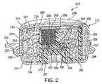
図2は、全体を参照番号210によって示された、本発明の一態様による2段式二段点火式インフレ−タを示し、静的状態または状況、たとえば起動前の状態で示されている。インフレ−タデバイス210は、上記のインフレ−タデバイス110とある程度似ており、すなわち、全体的に円筒状外径を有し、2つの構造部品、すなわち下側外殻または基底部分214と、上側外殻または拡散キャップ部分216とから形成されるものなど、ハウジング構造212を備え、それら構造部品は、望ましくはアルミニウムおよび/または鋼材から製作することができ、適切な溶接工程を適用することによって、適切に一体に接合または結合することができる。ハウジング212は、通常または一般に、約1以下の長さ対直径の比を有し、車両の操舵輪の形状に具合よく対応し、それによって美的に満足いくような組立てを容易にする寸法および形状に設定されるなど、平たい円板形状の円筒の全体形状で示されている。
FIG. 2 illustrates a two-stage, two-stage ignition inflector, generally designated by
拡散キャップ部分216は全体に逆さの鉢の形であり、上壁220と、円筒形側壁222とを備え、円筒形側壁222は、離隔配置、好ましくはほぼ一様に離隔配置された複数のガス出口ポート224を備える。
The
より詳細に、以下に説明されるように、インフレ−タデバイス210が上記のインフレ−タデバイス110とおそらく最も顕著に異なるのは、インフレ−タデバイス210の基底部分214が、インフレ−タデバイス110に示された複数の装着開口、たとえば装着開口126および130ではなくて、インフレ−タデバイスまたはアセンブリに関して使用するために、好適には、ただ1つだけの装着開口226を備えることである。
In more detail, as will be described below, the
基底部分214は、また、図示のように、インフレ−タアセンブリ210を車両に取り付けるのに使用されるインターフェース取付部を形成する働きができるように、半径方向外方へ張り出す周縁ブラケット232を備える。
The
ハウジング212は、中心的な第1のチャンバ234を画成するように構成されている。第1のチャンバ234は、通常は火工品の形態のような第1のガス生成物質235の一供給量を収容または格納している。
The
第1のチャンバ234内で、そこに入っている第1のガス生成物質と取り囲む関係にあるのは、フィルタアセンブリ240である。そのようなフィルタアセンブリは、たとえば、金属スクリーンやフィルタダンパパッドなどの多重層または多重巻から形成されるものなど、1つまたは複数の燃焼スクリーンまたはフィルタを備え得る。
Within the
インフレ−タアセンブリ210は、また、インフレ−タアセンブリの部品を適正な相対配置に保持し、アセンブリを通る望ましくない流れを防止するのに適切な構造として働くことができるような固定器具244を備える。
The
上記で確認されたように、インフレ−タデバイス210の基底部分214は、好適には、起爆デバイスまたはアセンブリに関して使用する装着開口226を1つしか備えていない。特に、二段点火式インフレ−タのために、本明細書に説明するような構造部品250を使用することによって、そのような利点が実現可能になる。この構造部品250は、モールド成形されたもの(モールド要素)251とすることができ、二段点火式起爆アセンブリ252を包有する。二段点火式起爆アセンブリ252は、連携する発火出力組成物254を有するような1次点火器253と、連携する発火出力組成物257を有するような2次点火器256を備える。二段点火式起爆アセンブリ252では、1次点火器253および2次点火器256は、構造部品250内に垂直方向に点火するよう配設されている。
As confirmed above, the
二段点火式起爆アセンブリ252では、電流が、第1のまたは順極性で1次点火器を通して流されて1次点火器を起動し、電流が、第2のまたは逆(第1の極性と比較して)極性で2次点火器を通して流されて少なくとも2次点火器を起動する。そのような起爆アセンブリが、2012年11月29日出願の米国特許出願第13/688,839号、題名「DUPLEX ACTUATION SYSTEM FOR INFLATABLE RESTRAINTS」(整理番号:AAI−70327)の主題であり、参照によりその全体が組み込まれる。
In the double-
図示のように、二段点火式点火器252の1次点火器253および2次点火器256は、少なくとも部分的にそれぞれのプラスチックシール258および259などの手段によって、モールドプロセス中にモールドプラスチック251内に包含させることができる。これにより、好適には、各点火器用の発火出力組成物のシール、封じ込め、電気絶縁、およびブレイクアウトを行うことができる。対照的に、現在のインフレ−タデバイスでのシール、封じ込め、電気絶縁、およびブレイクアウトは、通常、金属収容カップおよび電気絶縁スリーブを使用することによって行われる。当業者および本明細書に示される教示を得た者は理解するように、これら2つの部品を無くすことによって、部品の総数、設計の複雑さ、および製造プロセスを有益に減少させ、さらに、製造および生産コストを低減することができる。
As illustrated,
ただし望むなら、二段点火式点火器は別法として、それぞれの点火器用のそれぞれの発火出力組成物を収容するために、適切な金属製などの収容カップと併せて使用することができることを理解されたい。 However, if desired, as two-stage ignition igniter Alternatively, to accommodate the respective ignition output composition for each igniter, that can be used in conjunction with the housing cup such as a suitable metal I want you to understand.
しかしそのような場合でも、本明細書に記載されるような二段点火式点火器を使用することによって、その関連工程およびコストと共に、望ましくは第2の起爆アダプタの必要性を無くし、さらに以下に説明されるように、この新規のインフレ−タ技術を既存の最新の単段インフレ−タ技術に整合させ易くする。 However, even in such a case, the use of a two-stage igniter as described herein, along with its associated processes and costs, desirably eliminates the need for a second detonation adapter, and further This new inflector technology makes it easier to match existing state-of-the-art single-stage inflector technology, as described in.
図2に示されるように、部品のモールド成形された要素251は、望ましくは、基底部分214と一体に、装着開口226の位置またはその近傍にくるように成形される。成形は、一部の最新式単段インフレ−タに従来使用されているプロセスである。従来の2段式インフレ−タでは、起動時のインフレ−タデバイスの安全な作動を確保するのに要する、チャンバ壁強度の必要な度合またはレベルを維持するために、点火装置アダプタをインフレ−タデバイスのチャンバ壁に接合するのに溶接する必要がある。インフレ−タチャンバ壁に装着開口を1つだけしか必要としないことによって、インフレ−タチャンバ壁の強度が十分に維持されるので、今や好適に成形プロセスを2段式インフレ−タに適用することができる。
As shown in FIG. 2,
インフレ−タデバイス210では、部品250は、また、一体に成形された第1段点火装置ブースタカップ260を備える。ブースタカップ260は、望ましくは、作動時に反応生成物を排出することができる離散したガス出口開口262を備える。ガス出口開口262もまた、望ましくは、製造および生産コストを低減させるように、第1段点火装置ブースタカップに一体に成形される。ガス出口開口262は、図示のように、それを覆う薄い保護用ブレイクアウト膜264を備えまたは有し得、それによって、点火装置ブースタカップ260の内容物を外部の影響から遮蔽または保護し、さらに、インフレ−タデバイスの作動中に適切に開口またはブレイクアウトすることができる。
In the
ブースタカップ260は、望ましくは、ある量の適切な点火剤または点火ブースタ物質266を備えまたは包含し、当技術分野では既知のように、それによって、適正な起動時に、第1のガス生成物質235の望ましい点火を適切に助長し促進する。
対応する閉鎖蓋268がブースタカップ260と連携して、望ましくは、ブースタ物質266を適正な配置に維持する。
A
上記のインフレ−タデバイス110と同様に、インフレ−タデバイス210でも、第1のチャンバ234が第2のチャンバ282をやはり格納または収容する。ただし、インフレ−タデバイス210では、部品250がまた、一体に成形された第2段ガス発生剤カップ284も備える。
Similar to the
第2のチャンバ282が、また、対応または連携する閉鎖蓋285を備える。
The
上記のインフレ−タデバイス110と同様に、インフレ−タデバイス210でも、発生剤カップ284と閉鎖蓋285とが協働して発生剤カップ内室を形成し、それに、望ましくは、選択された量の第2のガス生成物質298が入れられる。第2のガス生成物質298は、通常、火工物質の形態でもよく、第1のガス生成物質235と比較して、組成、形状、大きさ、または形態が同じでも異なっていてもよい。
Similar to the
発生剤カップ284と閉鎖蓋285とは、さらに、望ましくは協働し、ガス生成物質298の反応によって形成された燃焼生成物が、適正かつ望ましく起動されたとき、第2のチャンバ282から出て第1のチャンバ234に入り、フィルタアセンブリ240および出口ポート224を通ってインフレ−タアセンブリ210から出て、連携するエアバッグクッション(図示せず)に入ることができるように働く。
The
第1段点火装置ブースタカップ260、ブースタカップガス出口開口262、ガス出口ブレイクアウト膜264、および第2段ガス発生剤カップ284をインフレ−タデバイス部品250に含める成形の特徴によって、インフレ−タの寸法、重量、および部品の数、ならびに設計の複雑さと製造プロセスおよびコストにおいて、著しい低減を実現することができる。ただし本発明は、本発明による望ましい部品に、そのような特徴を選択的に1つまたは複数取り込み、または取り込まないことにより、望み通りに実施することができることを理解されたい。
By the features of the molding including
本発明は上記で、図2に示され、1次点火器および2次点火器が部品内で垂直方向に点火するよう配置された二段点火式点火器を備えるインフレ−タデバイス210を特に参照して説明してきたが、それに必ずしも限定されずに、本発明をより広く実施できることが、当業者および本明細書に示された教示を得た者には理解されるであろう。
In the present invention described above, it is shown in Figure 2, the inflation includes a two-stage ignition igniter which is placed so that primary point firearms and secondary igniter ignites in the vertical direction in the parts - in particular the
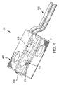
たとえば図3は、全体を参照番号310で示された、本発明の別の態様による、2段式二段点火式インフレ−タを示す。インフレ−タデバイス310は、静的状態または状況、たとえば起動前の状態で示されている。インフレ−タデバイス310は、上記のインフレ−タデバイス210にほぼ似ており、下側外殻または基底部分314と、上側外殻または拡散キャップ部分316とを備える。拡散キャップ部分316は、上壁320と、複数のガス出口ポート324を有する円筒形側壁322とを備える。基底部分314は同様に、好適には、起爆デバイスまたはアセンブリに関して使用する装着開口326を1つしか備えていない。基底部分314は、また図示のように、インフレ−タアセンブリ310を車両に取り付けるのに使用される、インターフェース取付部を形成する働きができるような周縁ブラケット332を備える。
For example, FIG. 3 shows a two-stage, two- stage ignition inflector, generally designated by
ハウジング312は、中心的な第1のチャンバ334を画成するように構成されている。第1のチャンバ334は、通常は火工品の形態のような第1のガス生成物質(図示せず)の一供給量を収容または格納している。第1のチャンバ334内で、そこに入っている第1のガス生成物質と取り囲む関係にあるのは、フィルタアセンブリ340である。インフレ−タアセンブリ310もまた、上記のように固定器具344を備える。
The
インフレ−タデバイス210と同様に、インフレ−タデバイス310の基底部分314は、好適には、起爆デバイスまたはアセンブリに関して使用する装着開口326を1つしか備えていない。特に、二段点火式インフレ−タのために、本明細書に説明するような構造部品350を使用することによって、そのような利点が実現可能になる。構造部品350は、モールド要素351でもよく、二段点火式起爆アセンブリ352を包有する。二段点火式起爆アセンブリ352は、連携する発火出力組成物354を伴うような1次点火器353と、連携する発火出力組成物357を伴うような2次点火器356とを備える。二段点火式起爆アセンブリ352は、1次点火器353および2次点火器356が、それぞれの構造部品内で、垂直ではなく水平方向に点火するよう配設されている点で、インフレ−タデバイス210に示される二段点火式起爆アセンブリ252とは異なる。
Similar to the
二段点火式点火器252におけるように、二段点火式起爆アセンブリ352では、電流が、第1のまたは順極性で1次点火器を通して流されて1次点火器を起動し、電流が、第2のまたは逆(第1の極性と比較して)極性で2次点火器を通して流されて、少なくとも2次点火器を起動する。
As in the two-
図示のように、二段点火式点火器352の1次点火器353および2次点火器356は、少なくとも部分的に、それぞれのプラスチックシール358および359を介するなどして、成形プロセス中にモールドプラスチック351内に包含させることができる。
As shown, the
モールド要素351は、望ましくは、基底部分314と一体に、装着開口326の位置またはその近傍にくるように成形される。
The
部品350は、また、一体に成形された第1段点火装置ブースタカップ360を備える。ブースタカップ360は、望ましくは、作動時に反応生成物を排出することができる離散したガス出口開口362を備える。ガス出口開口362もまた、望ましくは、製造および生産コストを低減させるように、第1段点火装置ブースタカップに一体に成形される。ガス出口開口362は、図示のように、それを覆う薄い保護用ブレイクアウト膜364を備えまたは有し得、それによって、点火装置ブースタカップ360の内容物を外部の影響から遮蔽または保護し、さらに、インフレ−タデバイスの作動中に適切に開口またはブレイクアウトすることができる。
ブースタカップ360は、望ましくは、ある量の適切な点火装置または点火ブースタ物質(図示せず)を備えまたは包含し、当技術分野では既知のように、それによって、適正な起動時に、第1のガス生成物質の望ましい点火を適切に助長し促進する。
The
対応する閉鎖蓋368がブースタカップ360と連携して、望ましくは、ブースタ物質を適正な配置に維持する。
A
インフレ−タデバイス210と同様に、第1のチャンバ334が第2のチャンバ382をやはり格納または収容する。インフレ−タデバイス310では、部品350が、一体に成形された第2段ガス発生剤カップ384を備える。
Similar to the
第2のチャンバ382が、また、対応または連携する閉鎖蓋385を備える。
The
発生剤カップ384と閉鎖蓋385とが協働して発生剤カップ内室を形成し、それに、望ましくは、選択された量の第2のガス生成物質(図示せず)が入れられる。
The generator cup 384 and the
発生剤カップ384と閉鎖蓋385とは、さらに、望ましくは協働し、そこに入っているガス生成物質の反応によって形成された燃焼生成物が、適正かつ望ましく起動されたとき、第2のチャンバ382から出て第1のチャンバ334に入り、フィルタアセンブリ340および出口ポート324を通ってインフレ−タアセンブリ310から出て、連携するエアバッグクッション(図示せず)に入ることができるように働く。
The generant cup 384 and
図4は、全体を参照番号410によって示された、本発明の一態様による二段点火式点火器、より具体的には、2ピン二段点火式点火器を示す。
FIG. 4 shows a two-stage igniter , more specifically a 2-pin two-stage igniter , according to one aspect of the present invention, generally designated by
二段点火式点火器410は、プリント回路基板(PCB)419上に、またはそれを用いて配設された、1次点火器412および2次段点火器414と、第1のダイオード416および第2のダイオード418とを備える。図示のように、そのような構成部品は、射出成型によって製作することができるような共通のハウジング420に、適切に格納または収容することができる。二段点火式点火器410は、作動電流を起爆アセンブリ410に適切に導くように働くことができるような、2つの曲がった接続ピン422を備える。
The two-
上記の二段点火式点火器252および二段点火式起爆アセンブリ352と同様に、2ピン二段点火式点火器410でも、電流が、第1または順極性で1次点火器412に流されて1次点火器を起動することができ、電流が、第2または逆(第1の極性に比較して)極性で2次点火器414に流されて、少なくとも2次点火器を起動することができる。
Like the two-
二段点火式点火器410は2つの曲がった接続ピン422を有するところが示されている。当業者および本明細書に示される教示を得た者は、必ずしもそれに限定されずに本発明を広く実施できることを理解するであろう。たとえば、特定の用途に望ましくまたは必要なら、その代わりに真直ぐのピンを用いることができる。さらに、二段点火式点火器410は、それら点火器が互いに偏位して反対向きに放出する点火器412と点火器414とを示すが、やはり、必ずしもそれに限定されずに本発明を広く実施できる。たとえば、特定の用途に望ましくまたは必要なら、適切な二段点火式点火器は、ほぼ同じ方向に放出する1次点火器および2次点火器を包含しまたは備え得、またはそれら点火器が偏位状態ではなく互いに直接反対向きに置かれている。
The two-
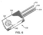
図5および6は、全体を参照番号510によって示された、本発明の一態様による二段点火式点火器、より具体的には、3ピン二段点火式点火器を示す。
FIGS. 5 and 6 illustrate a two-stage igniter , more specifically a 3-pin two-stage igniter , according to one aspect of the present invention, generally designated by
3ピン二段点火式点火器510は、第1の側方接続ピン512および第2の側方接続ピン514と、中央接続ピン516とを含む3つの接続ピンを備える。3ピン二段点火式点火器510は、第1のポケット520および第2のポケット530をそれぞれ持つハウジング519を有する。それぞれのポケット520および530内部に、それぞれのブリッジワイヤ要素540および542がそれぞれ配設され、それらブリッジワイヤ要素は、中央接続ピン516をアースとして共有している。たとえば、第1のブリッジワイヤ要素540は、第1のポケット520の中に見られるように、第1の側方接続ピン512と中央接続ピン516との間に延在する。同じように、第2のブリッジワイヤ要素542は、第2のポケット530の中に見られるように、第2の側方接続ピン514と中央接続ピン516との間に延在する。
The 3-pin two-stage
上記で確認されたように、上記のような構造部品は、望ましくは、成形プロセスによって製造または形成することができる。成形プロセスでは、通常、成形型の様々な空洞を通してプラスチック材を移動させるためにかなりの大きさの圧力を掛ける必要がある。 As confirmed above, a structural component as described above can desirably be manufactured or formed by a molding process. The molding process typically requires significant pressure to move the plastic material through the various cavities of the mold.
好適には、本明細書に説明された態様を実施することによって、そのような成形圧力が、また、望ましくは、それぞれの起爆発火出力組成物を固結するように働くことができる。 Preferably, by implementing the embodiments described herein, such molding pressure can also desirably work to consolidate the respective pyrotechnic output composition.
たとえば、図7は、起爆アセンブリ728の電気ブリッジ724に隣接する未固結の発火出力組成物720上への固結力(矢印Fによって示される)の掛かり方を単純化して概略的に示す。
For example, FIG. 7 schematically illustrates schematically how the consolidation force (indicated by arrow F) is applied on an unconsolidated
図8は、今度は参照番号730によって示される起爆発火組成物が固結後の起爆アセンブリ728を示す。
Figure 8 is a detonator ignition composition now indicated by
そのような固結の結果としてまたはそれを介して、点火器の電気ブリッジと、連携する起爆発火出力組成物とによる、またはそれらの間の緊密な接触をより良好に確保することができ、もしくは強化することができる。これは、そのような固結が、通例、別個にまたは追加の加圧工程として行われる従来技術のアセンブリとはさらに対照的である。 As a result of or through such consolidation, an intimate contact with or between the electrical bridge of the igniter and the associated pyrotechnic output composition may be better ensured, or Can be strengthened. This is in contrast to prior art assemblies where such consolidation is typically performed separately or as an additional pressing step.
図9および10は、全体を参照番号910で示された、本発明の別の態様による2段式二段点火式インフレ−タを示し、図9は、静的状態または状況、たとえば起動前の状態のインフレ−タデバイス910を示す。
FIGS. 9 and 10 illustrate a two-stage, two-stage ignition inflector according to another aspect of the present invention, generally designated by
インフレ−タデバイス910は、たとえば、下側外殻または基底部分914と、上側外殻または拡散キャップ部分916とを有するようなハウジング912を備える点で、上記のインフレ−タデバイス210とほぼ同様である。拡散キャップ部分916は、上壁920と、複数のガス出口ポート924を有する円筒形側壁922とを備える。基底部分914は、同様に、好適には、起爆デバイスまたはアセンブリに関して使用する装着開口926を1つしか備えていない。基底部分914は、また、図示のように、インフレ−タアセンブリ910を車両に取り付けるのに使用されるインターフェース取付部を形成する働きができるような周縁ブラケット932を備える。
The
ハウジング912は、中心的な第1のチャンバ934を画成するように構成されている。第1のチャンバ934は、当技術分野では既知のように、通常は火工品の形態のような第1のガス生成物質(図示せず)の一供給量を収容または格納している。第1のチャンバ934内で、そこに入っている第1のガス生成物質と取り囲む関係にあるのは、上記のようにフィルタアセンブリ940である。インフレ−タアセンブリ910は、また、やはり上記のように固定器具944を備える。
The
インフレ−タデバイス210と同様に、インフレ−タデバイス910の基底部分914は、好適には、起爆デバイスまたはアセンブリに関して使用する装着開口926を1つしか備えていない。特に、二段点火式インフレ−タのために、本明細書に説明するような構造部品950を使用することによって、そのような利点が実現可能になる。
Similar to the
図11を参照することによっておそらく最も良く分かるように、構造部品950は、モールド要素951でもよく、二段点火式起爆アセンブリ952を包有することができる。二段点火式起爆アセンブリ952(図12にも分離して示されている)は、連携する発火出力組成物954を有するような、1次点火器953と、連携する発火出力組成物957を有するような、2次点火器956とを備える。二段点火式起爆アセンブリ952は、作動電流を起爆アセンブリに適切に導くように働くことができるような2つの接続ピン959を有する。1次点火器953および2次点火器956は、上記で確認した、2012年11月29日出願の、参照によりその全体が組み込まれる、米国特許出願第13/688,839号、題名「DUPLEX ACTUATION SYSTEM FOR INFLATABLE RESTRAINTS」(整理番号:AAI−70327)に記載されているように、プリント回路基板(PCB)960を介して1つまたは複数のダイオード962に適切に接続される。
As perhaps best seen by referring to FIG. 11, the
インフレ−タデバイス210に示された二段点火式起爆アセンブリ252におけるように、二段点火式起爆アセンブリ952では、1次点火器953および2次点火器956は、それぞれの構造部品内で垂直方向に点火するよう配設されている。さらに、二段点火式点火器252におけるように、二段点火式起爆アセンブリ952では、電流が、第1のまたは順極性で1次点火器を通して流されて1次点火器を起動し、電流が、第2のまたは逆(第1の極性と比較して)極性で2次点火器を通して流されて少なくとも2次点火器を起動する。
Inflation - as in two-stage ignition
図示のように、二段点火式点火器952の1次点火器953および2次点火器956は、成型プロセス中にモールドプラスチック951内に包含させることができる。
As shown, the
図12は二段点火式起爆アセンブリ952を分離して示すが、図13および14は、本発明の一実施形態によってモールドプラスチック951内に適切に包含させられた二段点火式起爆アセンブリ952から全体的に構成されるようなモールド成形された二段式アセンブリ950を示す。図示のように、囲包成形材は、成型材料の通り溝として、または、インフレ−タアセンブリ内での二段点火式起爆アセンブリ952の望ましい配置および固定を容易にするために望ましくは備え得るような拘束または固定機構として、使用することができるような陥凹または空所970および972を望ましくは備え得る。たとえば、図9を参照することによっておそらくより良く分かるように、通し溝/固定機構970および972を介して、モールド成形された二段式アセンブリ950を、参照番号974によって示されるモールドコネクタなどによってインフレ−タ基底部914の内側ハブ上に適切に成形することができる。このプロセスは好ましくは、基底部に対する気密シールを生成しながら、望ましくは、モールド成形された二段式アセンブリ950を基底部914上に拘束または固定することができる。図15に示されるように、モールド成形された連結部974は、また、望ましくは、接続ピン959の周りにモールド成形されたコネクタポケット976を形成または生成することができる。
Although FIG. 12 shows the two-stage
次いで、インフレ−タデバイス910を組立てるためのプロセスを、図9および10を参照して説明する。図10を参照することによっておそらく最も良く分かるように、点火装置カップ980を、適切に、選択された点火ブースタ物質(図示せず)によって充填し、封止し、点火装置の缶982に挿入することができる。次いで、キャニスタリング984を点火装置の缶982に適切に圧入することができ、点火装置キャニスタアセンブリ全体をモールド成形された二段式アセンブリ950上、1次点火器953の周りに適切に圧力嵌めすることができ、モールド二段式アセンブリ950は、既に、インフレ−タ基底部914に固定されている。図10で分かるように、点火装置の缶982は、起動時、点火反応生成物を第1のチャンバ934の内容物に適切に連通させる孔または開口986を備える。
The process for assembling the
第2段カップ988をモールド成形された二段式アセンブリ950上に適切に圧力嵌めすることができる。第2段カップ988は、選択されたガス生成物質(図示せず)によって適切に充填することができる。第2段蓋またはキャップ990を、第2段カップ988に適切に圧入またはその上に圧力嵌めして、その内容物を適切に封入することができる。
The
上記のように望ましい設計のフィルタアセンブリ940を、インフレ−タ基底部914に適切に圧力嵌めすることができる。第1のチャンバ934を、選択されたガス生成物質(図示せず)によって適切に充填することができる。ダンパパッド992を、フィルタ940に挿入することができ、固定器具944を、フィルタ940上、または適宜その周りに適切に圧力嵌めすることができる。拡散キャップ部分916を、溶接、または部品を一体に結合する他の選択された形態などを用いて、基底部アセンブリ914に適切に固定することができる。
A
本明細書に記載され提供された二段点火式インフレ−タは、IPおよびOOP要件を共に満たすのに必要な性能を達成する。より具体的には、二段点火式起爆アセンブリとそれらアセンブリを包有する構造部品とを一体化し用いることによって、本明細書に説明されるように、インフレ−タの寸法、重量、および複雑さを低減することができる内部ハードウェアの変更が可能になる。これはさらに、部品数および製造プロセス数を減少させ、現在の最新技術のインフレ−タに勝るコスト削減を達成する。 The two-stage ignition inflators described and provided herein achieve the performance necessary to meet both IP and OOP requirements. More specifically, by integrating and using a two-stage ignition detonation assembly and the structural components that enclose the assemblies, as described herein, the size, weight, and complexity of the inflector can be reduced. It is possible to change internal hardware that can be reduced. This further reduces the number of parts and manufacturing processes and achieves cost savings over current state-of-the-art inflators.
本明細書に例示的に開示された本発明は、本明細書で具体的には開示されていない要素、部品、ステップ、部品、または含有物質のいずれを欠いても適切に実施することができる。 The present invention exemplarily disclosed in the present specification can be appropriately implemented without any elements, components, steps, components , or contained substances that are not specifically disclosed in the present specification. .
前述の詳細な説明において、本発明が、そのいくつかの好ましい実施形態に関して説明され、多くの細部が例示のために記述されてきたが、本発明にはさらに別の実施形態が可能であり、本明細書に記載された細部には、本発明の基本原理から逸脱することなくかなり変更することができるものがあることが、当業者には明らかであろう。 In the foregoing detailed description, the invention has been described with reference to several preferred embodiments thereof, and many details have been described for purposes of illustration, but the invention is capable of further embodiments, It will be apparent to those skilled in the art that the details described herein can be modified considerably without departing from the basic principles of the invention.
Claims (8)
前記ハウジング(212)の基底部分(214)に形成された単一の装着開口(226)に装着された構造部品(250)と、を備えた二段点火式インフレータ(210)であって、
前記構造部品(250)が、
第1の発火組成物(254)を有する第1の点火器(253)と、
第2の発火組成物(257)を有する第2の点火器(256)と、
前記第1の点火器(253)および前記第2の点火器(256)を包含するとともに、前記第1の点火器用のブースタ剤(266)が収容されるブースタカップ(260)として機能する部分、および前記第2の点火器用のガス発生剤(298)が収容されるガス発生剤カップ(284)として機能する部分を有するように一体成形されたモールドプラスチック(251)とを備え、
前記モールドプラスチック(251)は、前記ハウジング(212)における前記装着開口(226)を囲む壁が前記モールドプラスチックに挿入されるように成形され、
前記モールドプラスチック(251)が、前記第1の点火器(253)および前記第2の点火器(256)と電気作動上連携する単一のコネクタとして機能するポケット(976)を有する、
二段点火式インフレータ。 A housing (212) having at least one gas outlet opening (224);
A two-stage ignition inflator (210) comprising: a structural component (250) mounted in a single mounting opening (226) formed in a base portion (214) of the housing (212);
The structural component (250) is
A first igniter (253) having a first ignition composition (254);
A second igniter (256) having a second ignition composition (257);
A portion that includes the first igniter (253) and the second igniter (256) and functions as a booster cup (260) in which the booster agent (266) for the first igniter is accommodated; And a molded plastic (251) integrally molded so as to have a portion functioning as a gas generant cup (284) in which the gas generant (298) for the second igniter is accommodated,
The molded plastic (251) is molded such that a wall surrounding the mounting opening (226) in the housing (212) is inserted into the molded plastic,
The molded plastic (251) has a pocket (976) that functions as a single connector in electrical cooperation with the first igniter (253) and the second igniter (256),
Two-stage ignition inflator.
Applications Claiming Priority (3)
| Application Number | Priority Date | Filing Date | Title |
|---|---|---|---|
| US13/688,893 | 2012-11-29 | ||
| US13/688,893 US9010803B2 (en) | 2012-11-29 | 2012-11-29 | Duplex firing inflator |
| PCT/US2013/069064 WO2014085052A1 (en) | 2012-11-29 | 2013-11-08 | Duplex firing inflator |
Publications (3)
| Publication Number | Publication Date |
|---|---|
| JP2016504231A JP2016504231A (en) | 2016-02-12 |
| JP2016504231A5 JP2016504231A5 (en) | 2017-10-05 |
| JP6227002B2 true JP6227002B2 (en) | 2017-11-08 |
Family
ID=50772135
Family Applications (1)
| Application Number | Title | Priority Date | Filing Date |
|---|---|---|---|
| JP2015545062A Active JP6227002B2 (en) | 2012-11-29 | 2013-11-08 | Two-stage ignition type inflator |
Country Status (5)
| Country | Link |
|---|---|
| US (1) | US9010803B2 (en) |
| EP (1) | EP2925571B1 (en) |
| JP (1) | JP6227002B2 (en) |
| CN (1) | CN104870263B (en) |
| WO (1) | WO2014085052A1 (en) |
Families Citing this family (12)
| Publication number | Priority date | Publication date | Assignee | Title |
|---|---|---|---|---|
| US8444179B2 (en) * | 2006-12-06 | 2013-05-21 | Trw Vehicle Safety Systems Inc. | Dual stage air bag inflator |
| US9073512B1 (en) * | 2012-07-23 | 2015-07-07 | Tk Holdings Inc. | Gas generating system with gas generant cushion |
| US9550471B1 (en) | 2013-06-30 | 2017-01-24 | Tk Holdings Inc. | Gas generating system movable divider |
| CA2857652A1 (en) * | 2013-07-24 | 2015-01-24 | William R. Bliss | Protective canisters for incendiary devices |
| US10281248B2 (en) * | 2015-11-11 | 2019-05-07 | Northrop Grumman Innovation Systems, Inc. | Gas generators, launch tube assemblies including gas generators, and related systems and methods |
| CN105644491B (en) * | 2016-01-04 | 2017-12-01 | 百利得(湖州)汽车安全系统有限公司 | Inflatable gas generator is ignited in a kind of secondary delay |
| DE102016002937A1 (en) * | 2016-03-11 | 2017-09-14 | Trw Airbag Systems Gmbh | Hybrid gas generator, gas bag unit and vehicle safety system with such a hybrid gas generator and method for forming a shock wave |
| WO2017197389A1 (en) * | 2016-05-13 | 2017-11-16 | Tk Holdings Inc. | Smart initiator assembly |
| DE102016213002B4 (en) * | 2016-07-15 | 2019-02-14 | Joyson Safety Systems Germany Gmbh | Gas generator for a gas bag module of a vehicle occupant restraint system and method for producing a gas generator |
| JP6910828B2 (en) * | 2017-04-03 | 2021-07-28 | 日本化薬株式会社 | Gas generator |
| US10663269B2 (en) | 2018-05-23 | 2020-05-26 | Autoliv Asp, Inc. | Initiator grounding clip |
| CN110228441B (en) * | 2019-06-25 | 2024-04-16 | 延锋汽车智能安全系统有限责任公司 | Gas generator, method for manufacturing the same, and airbag |
Family Cites Families (42)
| Publication number | Priority date | Publication date | Assignee | Title |
|---|---|---|---|---|
| US3225695A (en) | 1961-08-04 | 1965-12-28 | Space Recovery Systems Inc | Pyrotechnic bridge detonating circuit with zener diode circuit controlling switching of scr |
| US4998751A (en) | 1990-03-26 | 1991-03-12 | Morton International, Inc. | Two-stage automotive gas bag inflator using igniter material to delay second stage ignition |
| US5179248A (en) | 1991-10-08 | 1993-01-12 | Scb Technologies, Inc. | Zener diode for protection of semiconductor explosive bridge |
| US5309841A (en) | 1991-10-08 | 1994-05-10 | Scb Technologies, Inc. | Zener diode for protection of integrated circuit explosive bridge |
| EP0705740B1 (en) | 1993-06-28 | 2001-11-21 | Autoliv Japan Ltd. | Starting device for crew protecting system |
| US5505488A (en) * | 1995-04-03 | 1996-04-09 | Morton International, Inc. | Integral airbag cushion retainer, filter and diffuser |
| US5603525A (en) * | 1995-06-22 | 1997-02-18 | Trw Inc. | Air bag inflator initiator housing with stored fluid pressure relief |
| FR2740545B1 (en) | 1995-10-30 | 1997-12-05 | Livbag Snc | PYROTECHNIC GAS GENERATOR, VARIABLE FLOW RATE, FOR PROTECTIVE CUSHIONS |
| FR2763548B1 (en) * | 1997-05-23 | 1999-06-18 | Livbag Snc | PYROTECHNIC ADAPTIVE GAS GENERATOR WITH TUBULAR CHAMBERS FOR PROTECTIVE CUSHION |
| US6189924B1 (en) | 1997-11-21 | 2001-02-20 | Autoliv Asp, Inc. | Plural stage inflator |
| FR2772909B1 (en) * | 1997-12-22 | 2000-01-28 | Livbag Snc | ELECTRO-PYROTECHNIC INITIATOR WITH THREE ELECTRICAL CONNECTIONS |
| US6131947A (en) | 1998-01-23 | 2000-10-17 | Trw Inc. | Electrical connector for air bag inflator |
| US6032979C1 (en) | 1998-02-18 | 2001-10-16 | Autoliv Asp Inc | Adaptive output inflator |
| US6295935B1 (en) * | 1998-04-27 | 2001-10-02 | Trw Inc. | Initiator for air bag inflator |
| US6145877A (en) * | 1998-05-29 | 2000-11-14 | Autoliv Asp, Inc. | Pressure vessel inflator having a preformed opening feature |
| JP3220443B2 (en) * | 1998-11-30 | 2001-10-22 | ダイセル化学工業株式会社 | Gas generator for airbag and airbag device |
| EP1059211A3 (en) * | 1999-02-16 | 2001-01-03 | Daicel Chemical Industries, Ltd. | Multistage gas generator for air bag and air bag apparatus |
| US6701849B2 (en) * | 1999-03-05 | 2004-03-09 | Trw Inc. | Dual stage air bag inflator with secondary propellant cap |
| US6199906B1 (en) * | 1999-08-12 | 2001-03-13 | Breed Automotive Technology, Inc. | Dual stage pyrotechnic inflator |
| US6189927B1 (en) | 1999-12-16 | 2001-02-20 | Autoliv Asp, Inc. | Adaptive output inflator |
| JP5008809B2 (en) * | 2000-03-13 | 2012-08-22 | 日本化薬株式会社 | Gas generator |
| US6659500B2 (en) | 2000-05-11 | 2003-12-09 | Automotive Systems Laboratory, Inc. | Multi-chamber inflator |
| WO2001094162A1 (en) * | 2000-06-08 | 2001-12-13 | Daicel Chemical Industries, Ltd. | Gas generator for air bag and air bag device |
| FR2813118B1 (en) | 2000-08-17 | 2003-03-07 | Livbag Snc | ELECTRO-PYROTECHNIC IGNITER WITH TWO IGNITION HEADS AND USE IN AUTOMOTIVE SAFETY |
| WO2003022645A1 (en) * | 2001-08-09 | 2003-03-20 | Nippon Kayaku Kabushiki-Kaisha | Gas generator |
| US6702323B2 (en) * | 2001-09-25 | 2004-03-09 | Trw Inc. | Air bag module with pressure regulator |
| US7004500B2 (en) | 2002-03-19 | 2006-02-28 | Paul Dinsdale | Dual stage inflator with extended gas delivery for a vehicular airbag system |
| JP3906910B2 (en) * | 2002-03-29 | 2007-04-18 | トヨタ自動車株式会社 | initiator |
| US7150227B2 (en) * | 2003-06-03 | 2006-12-19 | Daicel Chemical Industries, Ltd. | Multi-stage ignition type gas generator |
| US7044502B2 (en) * | 2004-02-24 | 2006-05-16 | Key Safety Systems, Inc. | Dual stage pyrotechnic driver inflator |
| US7607688B2 (en) * | 2004-02-25 | 2009-10-27 | Daicel Chemical Industries, Ltd. | Rupturable member |
| JP2005255032A (en) | 2004-03-12 | 2005-09-22 | Denso Corp | Occupant protection device for vehicle |
| JP4400340B2 (en) | 2004-06-30 | 2010-01-20 | 株式会社デンソー | Occupant protection system |
| US7347448B2 (en) | 2004-10-19 | 2008-03-25 | Autoliv Asp, Inc. | Inflator device for airbag installations |
| US20070057496A1 (en) * | 2005-06-08 | 2007-03-15 | Daicel Chemical Industries, Ltd. | Gas generator for air bag |
| US7320479B2 (en) * | 2005-10-03 | 2008-01-22 | Key Safety Systems, Inc. | Hybrid inflator |
| US7374204B2 (en) | 2005-11-28 | 2008-05-20 | Autoliv Asp, Inc. | Inflator second stage combustion control |
| US7597353B2 (en) | 2006-05-25 | 2009-10-06 | Autoliv Asp, Inc. | Inflator device having an annular inflation gas discharge opening |
| FR2922007A1 (en) * | 2007-10-03 | 2009-04-10 | Livbag Soc Par Actions Simplif | PYROTECHNIC GAS GENERATOR FOR AUTOMOBILE SAFETY, DISCOIDED |
| US7950693B2 (en) | 2008-05-20 | 2011-05-31 | Autoliv Asp, Inc. | Dual stage inflator |
| CA2738845C (en) * | 2008-09-30 | 2017-11-07 | Trw Airbag Systems Gmbh | Inflator, method of manufacturing the same and module including said inflator |
| CN103338981A (en) * | 2011-01-07 | 2013-10-02 | 日本化药株式会社 | Gas generator |
-
2012
- 2012-11-29 US US13/688,893 patent/US9010803B2/en active Active
-
2013
- 2013-11-08 CN CN201380061541.9A patent/CN104870263B/en not_active Expired - Fee Related
- 2013-11-08 EP EP13859366.0A patent/EP2925571B1/en not_active Not-in-force
- 2013-11-08 WO PCT/US2013/069064 patent/WO2014085052A1/en active Application Filing
- 2013-11-08 JP JP2015545062A patent/JP6227002B2/en active Active
Also Published As
| Publication number | Publication date |
|---|---|
| US9010803B2 (en) | 2015-04-21 |
| CN104870263A (en) | 2015-08-26 |
| CN104870263B (en) | 2019-03-05 |
| EP2925571A4 (en) | 2015-11-18 |
| EP2925571B1 (en) | 2018-08-29 |
| WO2014085052A1 (en) | 2014-06-05 |
| JP2016504231A (en) | 2016-02-12 |
| US20140144340A1 (en) | 2014-05-29 |
| EP2925571A1 (en) | 2015-10-07 |
Similar Documents
| Publication | Publication Date | Title |
|---|---|---|
| JP6227002B2 (en) | Two-stage ignition type inflator | |
| US7950693B2 (en) | Dual stage inflator | |
| EP1658204B1 (en) | Pyrotechnique side impact inflator | |
| KR100646586B1 (en) | Gas generator for air bag and air bag device | |
| US6659500B2 (en) | Multi-chamber inflator | |
| US7207597B2 (en) | Gas generator for air bag and air bag apparatus | |
| EP1775180A2 (en) | Dual stage hybrid airbag inflator | |
| EP2952394B1 (en) | Gas generator | |
| WO2000032446A1 (en) | Air bag gas generator and air bag device | |
| JP2004520997A6 (en) | 2-chamber inflator | |
| JP2004520997A (en) | 2-chamber inflator | |
| JP2016504231A5 (en) | ||
| JP2009286218A (en) | Gas generator | |
| WO2001068415A1 (en) | Gas generator | |
| JPWO2002083464A1 (en) | Gas generator | |
| JP4079329B2 (en) | Gas generator | |
| JP4303132B2 (en) | Inflator | |
| JP2005521582A (en) | 2-stage inflator with multiple chambers | |
| JP2004175335A (en) | Airbag inflator | |
| JP3790669B2 (en) | Gas generator for airbag and airbag device | |
| JP2010260388A (en) | Gas generator | |
| JP2000313304A (en) | Air bag gas generator and air bag device | |
| JP4860809B2 (en) | Gas generator for airbag and airbag device | |
| KR20240042002A (en) | dual stage inflator | |
| JP2010159051A (en) | Gas generator |
Legal Events
| Date | Code | Title | Description |
|---|---|---|---|
| A131 | Notification of reasons for refusal |
Free format text: JAPANESE INTERMEDIATE CODE: A131 Effective date: 20160614 |
|
| A977 | Report on retrieval |
Free format text: JAPANESE INTERMEDIATE CODE: A971007 Effective date: 20160616 |
|
| A601 | Written request for extension of time |
Free format text: JAPANESE INTERMEDIATE CODE: A601 Effective date: 20160913 |
|
| A601 | Written request for extension of time |
Free format text: JAPANESE INTERMEDIATE CODE: A601 Effective date: 20161110 |
|
| A521 | Request for written amendment filed |
Free format text: JAPANESE INTERMEDIATE CODE: A523 Effective date: 20161213 |
|
| A131 | Notification of reasons for refusal |
Free format text: JAPANESE INTERMEDIATE CODE: A131 Effective date: 20170131 |
|
| A524 | Written submission of copy of amendment under article 19 pct |
Free format text: JAPANESE INTERMEDIATE CODE: A524 Effective date: 20170426 |
|
| A131 | Notification of reasons for refusal |
Free format text: JAPANESE INTERMEDIATE CODE: A131 Effective date: 20170523 |
|
| A524 | Written submission of copy of amendment under article 19 pct |
Free format text: JAPANESE INTERMEDIATE CODE: A524 Effective date: 20170822 |
|
| TRDD | Decision of grant or rejection written | ||
| A01 | Written decision to grant a patent or to grant a registration (utility model) |
Free format text: JAPANESE INTERMEDIATE CODE: A01 Effective date: 20170912 |
|
| A61 | First payment of annual fees (during grant procedure) |
Free format text: JAPANESE INTERMEDIATE CODE: A61 Effective date: 20171010 |
|
| R150 | Certificate of patent or registration of utility model |
Ref document number: 6227002 Country of ref document: JP Free format text: JAPANESE INTERMEDIATE CODE: R150 |
|
| R250 | Receipt of annual fees |
Free format text: JAPANESE INTERMEDIATE CODE: R250 |
|
| R250 | Receipt of annual fees |
Free format text: JAPANESE INTERMEDIATE CODE: R250 |
|
| R250 | Receipt of annual fees |
Free format text: JAPANESE INTERMEDIATE CODE: R250 |