JP6221278B2 - Biological information detection device - Google Patents
Biological information detection device Download PDFInfo
- Publication number
- JP6221278B2 JP6221278B2 JP2013054493A JP2013054493A JP6221278B2 JP 6221278 B2 JP6221278 B2 JP 6221278B2 JP 2013054493 A JP2013054493 A JP 2013054493A JP 2013054493 A JP2013054493 A JP 2013054493A JP 6221278 B2 JP6221278 B2 JP 6221278B2
- Authority
- JP
- Japan
- Prior art keywords
- subject
- convex portion
- light
- pressure
- biological information
- Prior art date
- Legal status (The legal status is an assumption and is not a legal conclusion. Google has not performed a legal analysis and makes no representation as to the accuracy of the status listed.)
- Active
Links
Images


Landscapes
- Measuring Pulse, Heart Rate, Blood Pressure Or Blood Flow (AREA)
Description
本発明は、生体情報検出装置等に関する。 The present invention relates to a biological information detection device and the like.
従来より、人間の脈波等の生体情報を検出する生体情報検出装置が知られている。特許文献1、2には、このような生体情報検出装置の一例である脈拍計の従来技術が開示されている。脈拍計は、例えば腕、手首、指等に装着されて、人体の心拍に由来する拍動を検出して、脈拍数を測定する。
2. Description of the Related Art Conventionally, a biological information detection apparatus that detects biological information such as a human pulse wave is known.
特許文献1、2に開示される脈拍計は、光電式の脈拍計であり、その検出部(脈波センサー)は、被検体(被検出部位)に向けて光を発光する発光部と、被検体からの光(生体情報を有する光)を受光する受光部を有する。この脈拍計では、血流量の変化を受光量の変化として検出することで、脈波を検出している。そして特許文献1には、手首に装着するタイプの脈拍計が開示され、特許文献2には、指に装着するタイプの脈拍計が開示されている。
The pulsometers disclosed in
これらの従来技術では、発光部からの光や被検体からの光を透過する透光部材が設けられ、この透光部材が、被検体(手首や指の肌等)との接触面を有している。そして、この透光部材の接触面に凸部を設ければ、被検体の肌と接触する際に押圧をかけやすくなる。 In these conventional techniques, a translucent member that transmits light from the light emitting unit and light from the subject is provided, and this translucent member has a contact surface with the subject (such as the wrist or finger skin). ing. And if a convex part is provided in the contact surface of this translucent member, it will become easy to apply a press when contacting with the skin of a subject.
しかしながら、その副作用として、体動による生体情報検出装置の機器の揺れや、生体情報検出装置を装着するユーザーの手の動き(例えばグーパーの動作)などにより生じる押圧変動の影響を受けやすくなる。押圧変動が大きいということは、生体情報の検出信号に重畳する体動ノイズ成分が大きいということを意味する。 However, as a side effect, it is easily affected by fluctuations in the pressure of the biological information detecting device due to body movements, movements of the user's hand wearing the biological information detecting device (for example, movement of a gooper), and the like. A large pressure fluctuation means that a body motion noise component superimposed on a detection signal of biological information is large.
また、例えば荷重機構による荷重が少ない場合等において、凸部により十分な初期押圧を被検体に与えることができないと、適正な生体情報の検出信号を得ることができないという課題がある。 In addition, for example, when the load by the load mechanism is small, there is a problem that an appropriate biometric information detection signal cannot be obtained unless sufficient initial pressing is applied to the subject by the convex portion.
本発明の幾つかの態様によれば、押圧変動等による悪影響を低減しながら適正な初期押圧を被検体に与えることが可能な生体情報検出装置等を提供することができる。 According to some aspects of the present invention, it is possible to provide a biological information detection apparatus and the like that can apply an appropriate initial pressure to a subject while reducing adverse effects due to pressure fluctuations and the like.
本発明の一態様は、被検体からの光を受光する受光部を有する検出部と、生体情報検出装置の前記被検体に接触する筺体面側に設けられ、前記被検体からの光を透過し、かつ前記被検体の生体情報の測定時に前記被検体に接触して押圧を与える凸部を有する透光部材と、前記筺体面において前記凸部を囲むように設けられ、前記凸部が前記被検体に与える押圧を抑制する押圧抑制部と、を含み、前記筺体面に直交する方向での前記凸部の高さから前記押圧抑制部の高さを減じた値をΔhとした場合に、Δh>0である生体情報検出装置に関係する。 One embodiment of the present invention is provided on a body surface side of a biological information detection device that contacts a subject, and having a light receiving unit that receives light from the subject, and transmits light from the subject. And a translucent member having a convex portion that comes into contact with and presses the subject when measuring biological information of the subject, and is provided so as to surround the convex portion on the housing surface, and the convex portion A pressure suppression part that suppresses the pressure applied to the specimen, and Δh is a value obtained by subtracting the height of the pressure suppression part from the height of the convex part in a direction orthogonal to the housing surface. It is related to a biological information detection device where> 0.
本発明の一態様によれば、被検体の生体情報の測定時に透光部材の凸部が被検体に接触し、この透光部材を通過する光を、検出部の受光部が受光することで、被検体の生体情報が検出される。そして本発明の一態様では、凸部が被検体に対して与える押圧を抑制する押圧抑制部が、凸部を囲むように設けられると共に、凸部の高さから押圧抑制部の高さを減じた値であるΔhについて、Δh>0の関係が成り立っている。このように、Δhとなるように凸部が突出することで、少ない荷重で凸部により適正な初期押圧を被検体に与えることが可能になる。そして、凸部が与える押圧を押圧抑制部により抑制することで、押圧変動等を低減することが可能になる。従って、押圧変動等による悪影響を低減しながら適正な初期押圧を被検体に与えることが可能な生体情報検出装置を提供できる。 According to one aspect of the present invention, when the biological information of the subject is measured, the convex portion of the translucent member comes into contact with the subject, and the light receiving unit of the detection unit receives light passing through the translucent member. The biological information of the subject is detected. And in one mode of the present invention, while the pressure suppression part which suppresses the press which a convex part gives to a subject is provided so that the convex part may be surrounded, the height of a pressure suppression part is reduced from the height of a convex part. The relationship Δh> 0 holds for Δh, which is the calculated value. Thus, by projecting the convex portion so as to be Δh, it is possible to apply an appropriate initial pressure to the subject with the convex portion with a small load. And it becomes possible to reduce a press fluctuation | variation etc. by suppressing the press which a convex part gives by a press suppression part. Therefore, it is possible to provide a biological information detection apparatus that can apply an appropriate initial pressure to a subject while reducing adverse effects due to pressure fluctuations.
また本発明の一態様では、前記凸部の押圧を発生させる荷重機構による荷重に対する前記凸部の押圧の変化量を押圧変化量とした場合に、前記押圧抑制部は、前記荷重機構の荷重が0〜FL1となる第1の荷重範囲での前記押圧変化量に対して、前記荷重機構の荷重がFL1よりも大きくなる第2の荷重範囲での前記押圧変化量が小さくなるように、前記凸部が前記被検体に与える押圧を抑制してもよい。 Moreover, in one aspect of the present invention, when the amount of change in pressing of the convex portion with respect to the load by the load mechanism that generates pressing of the convex portion is defined as the amount of pressing change, the pressing suppression portion is configured so that the load of the load mechanism is The convex change amount is reduced so that the pressure change amount in the second load range in which the load of the load mechanism is larger than FL1 is smaller than the pressure change amount in the first load range of 0 to FL1. You may suppress the press which a part gives to the said test object.
このように、第1の荷重範囲での押圧変化量に比べて第2の荷重範囲での押圧変化量が小さくなるように凸部の押圧を抑制すれば、凸部により適正な初期押圧を被検体に与えながら、凸部が被検体に与える押圧を抑制して押圧変動を低減することなどが可能になる。 As described above, if the pressing of the convex portion is suppressed so that the pressing change amount in the second load range is smaller than the pressing change amount in the first load range, an appropriate initial pressing is applied to the convex portion. While applying to the specimen, it is possible to reduce the pressure fluctuation by suppressing the pressure applied to the subject by the convex portion.
また本発明の一態様では、前記押圧抑制部は、前記凸部の周囲から外側に広がる押圧抑制面を有してもよい。 In the aspect of the invention, the pressing suppression portion may have a pressing suppression surface that spreads outward from the periphery of the convex portion.
このようにすれば、凸部の周囲から外側に広がる押圧抑制面を用いて、凸部が被検体に与える押圧を、均等に効率良く抑制できるようになる。 If it does in this way, the press which a convex part gives to a subject will be able to be controlled equally efficiently using the press restraint surface which spreads outside from the circumference of a convex part.
また本発明の一態様では、前記凸部の位置から所定方向において第1の距離だけ離れた位置を第1の位置とし、前記凸部の位置から前記所定方向において前記第1の距離よりも長い第2の距離だけ離れた位置を第2の位置とし、前記第1の位置における、前記筺体面に直交する方向での前記押圧抑制面の高さをHS1とし、前記第2の位置における、前記筺体面に直交する方向での前記押圧抑制面の高さをHS2とした場合に、HS1>HS2であってもよい。 In one embodiment of the present invention, a position that is separated from the position of the convex portion by a first distance in the predetermined direction is a first position, and is longer than the first distance in the predetermined direction from the position of the convex portion. The position separated by the second distance is the second position, the height of the pressure suppression surface in the direction perpendicular to the housing surface at the first position is HS1, and the position at the second position is HS1> HS2 may be sufficient when the height of the said pressure suppression surface in the direction orthogonal to a housing surface is set to HS2.
このようなHS1>HS2の関係が成り立てば、凸部から遠い場所での被検体との接触状態の変動等が要因となって、凸部の押圧変動等が生じるのを効果的に抑制できる。 If such a relationship of HS1> HS2 is established, it is possible to effectively suppress the occurrence of pressure fluctuation of the convex portion due to the variation of the contact state with the subject in a place far from the convex portion.
また本発明の一態様では、前記押圧抑制面は、前記筺体面に直交する方向での高さが、前記凸部の位置から所定方向へと向かうにつれて低くなるように傾斜していてもよい。 Moreover, in one aspect of the present invention, the pressure suppression surface may be inclined such that a height in a direction orthogonal to the housing surface decreases from a position of the convex portion toward a predetermined direction.
このような傾斜を設ければ、筺体面に直交する方向での押圧抑制面の高さが、凸部から離れるほど低くなるため、凸部から遠い場所での被検体との接触状態の変動等による悪影響を低減できる。 If such an inclination is provided, the height of the pressure suppression surface in the direction orthogonal to the housing surface decreases as the distance from the convex portion decreases, so the contact state with the subject at a location far from the convex portion, etc. The adverse effect due to can be reduced.
また本発明の一態様では、前記透光部材は、前記被検体側に少なくとも一部が突出する前記凸部と、前記凸部に対して、前記被検体側とは反対方向側である下方側に設けられるボディー部とを有し、前記ボディー部は、前記凸部の位置から、前記筺体面のカバー部材の下方に延在形成され、前記押圧抑制面は前記カバー部材の面であってもよい。 In one embodiment of the present invention, the translucent member includes the convex portion at least partially protruding toward the subject side, and a lower side that is opposite to the subject side with respect to the convex portion. A body portion provided on the housing surface, the body portion extending from a position of the convex portion to a position below the cover member of the housing surface, and the pressure suppressing surface may be a surface of the cover member. Good.
このようにすれば、ボディー部の上方のカバー部材を有効活用して、押圧抑制面を形成できるようになる。 If it does in this way, it becomes possible to form a press restraining surface using the cover member above the body part effectively.
また本発明の一態様では、第1の方向に直交する方向を第2の方向とし、前記第2の方向の反対方向を第3の方向とした場合に、前記押圧抑制面は、前記凸部の周囲において、少なくとも前記第1の方向、前記第2の方向及び前記第3の方向において連続した面であってもよい。 In one embodiment of the present invention, when the direction orthogonal to the first direction is the second direction and the direction opposite to the second direction is the third direction, the pressing suppression surface is the convex portion. The surface may be continuous in at least the first direction, the second direction, and the third direction.
このようにすれば、少なくとも第1、第2、第3の方向において凸部の周囲に存在する押圧抑制面により、凸部の押圧を抑制できるようになるため、均等で効率の良い押圧抑制が可能になる。 In this way, since the pressing of the convex portion can be suppressed by the pressing suppression surface existing around the convex portion in at least the first, second, and third directions, uniform and efficient pressure suppression is achieved. It becomes possible.
また本発明の一態様では、前記凸部は、前記押圧抑制面から前記被検体側に、Δh>0となるように突出していてもよい。 In the aspect of the invention, the convex portion may protrude from the pressure suppression surface to the subject side so that Δh> 0.
このようにΔh>0となるように凸部が押圧抑制面から突出していれば、凸部が被検体に接触して初期押圧を与えた後に、押圧抑制面が被検体に接触して、凸部が被検体に与える押圧を抑制できるようになる。 In this way, if the convex portion protrudes from the pressure suppression surface so that Δh> 0, the convex portion contacts the subject and gives an initial pressure, and then the pressure suppression surface contacts the subject and the convex portion The pressure applied to the subject by the unit can be suppressed.
また本発明の一態様では、前記透光部材と前記検出部の間又は前記透光部材と前記被検体との間又は前記透光部材内に設けられ、前記被検体と前記検出部の間の光路において前記被検体からの光を絞る絞り部を含んでもよい。 Moreover, in one mode of the present invention, it is provided between the translucent member and the detection unit, between the translucent member and the subject, or in the translucent member, and between the subject and the detection unit. A stop portion for narrowing light from the subject in the optical path may be included.
このような絞り部を設ければ、被検体との接触面の接触状態の変化等を要因とする迷光が生じた場合にも、この迷光が受光部に入射されることなどを抑制することができ、適正な生体情報の検出が可能になる。 Providing such a diaphragm unit prevents the stray light from entering the light receiving unit even when stray light is generated due to a change in the contact state of the contact surface with the subject. It is possible to detect appropriate biological information.
また本発明の一態様では、前記検出部は、前記被検体に対して光を出射する発光部を含み、前記透光部材は、前記発光部からの光を透過し、前記受光部と前記発光部との間に設けられる遮光部を、更に含んでもよい。 In the aspect of the invention, the detection unit includes a light emitting unit that emits light to the subject, and the light transmitting member transmits light from the light emitting unit, and the light receiving unit and the light emitting unit. A light-shielding part provided between the two parts may be further included.
このような遮光部を設ければ、発光部からの直接光が受光部に入射されることなどを抑制することができ、適正な生体情報の検出が可能になる。 By providing such a light-shielding part, it is possible to suppress direct light from the light-emitting part from entering the light-receiving part, and it is possible to detect appropriate biological information.
また本発明の一態様では、0.01mm≦Δh≦0.5mmであってもよい。また本発明の一態様では、0.05mm≦Δh≦0.35mmであってもよい。 In one embodiment of the present invention, 0.01 mm ≦ Δh ≦ 0.5 mm may be satisfied. In one embodiment of the present invention, 0.05 mm ≦ Δh ≦ 0.35 mm may be satisfied.
このようにΔhを小さな値にすることで、生体情報を検出するために必要な最小限の押圧を被検体に与えながら、押圧変動等を要因とするノイズ成分の増加を抑制して、生体情報の検出信号の品位を向上することが可能になる。 In this way, by setting Δh to a small value, an increase in noise components caused by pressure fluctuations and the like is suppressed while giving the subject the minimum pressure necessary to detect biological information, and biological information It is possible to improve the quality of the detection signal.
また本発明の一態様では、前記凸部は、少なくとも前記被検体に接触する部分に曲面形状を有してもよい。 In the aspect of the invention, the convex portion may have a curved surface shape at least in a portion in contact with the subject.
このようにすれば、安定した接触状態で凸部により被検体に対して押圧を与えることが可能になる。 If it does in this way, it will become possible to give a press to a subject with a convex part in a stable contact state.
また本発明の一態様では、前記凸部の前記曲面形状の曲率半径をRとした場合に、R≧8mmであってもよい。 In one aspect of the present invention, R ≧ 8 mm may be satisfied, where R is a curvature radius of the curved surface shape of the convex portion.
このようにすれば、被検体の表面との接触状態が安定する曲率半径の条件で、効率良く押圧を与えることが可能になる。 In this way, it is possible to efficiently apply pressure under the condition of a radius of curvature that stabilizes the contact state with the surface of the subject.
また本発明の一態様では、前記凸部を有する前記透光部材は、前記筺体面に対して固設されていてもよい。 In one embodiment of the present invention, the translucent member having the convex portion may be fixed to the housing surface.
このようにすれば、例えば荷重機構等により荷重が与えられたときにも、透光部材を、筺体面に対して相対的に移動しないようにすることが可能になる。 In this way, for example, even when a load is applied by a load mechanism or the like, the translucent member can be prevented from moving relative to the housing surface.
また本発明の一態様では、前記押圧抑制部は、絶縁部材により形成されてもよい。 In the aspect of the invention, the pressing suppression portion may be formed of an insulating member.
このようにすれば、導電部材ではなく絶縁性の材料で形成される絶縁部材により押圧抑制部を形成して、凸部の押圧を抑制できるようになる。 If it does in this way, a press suppression part can be formed with the insulating member formed with an insulating material instead of a conductive member, and it becomes possible to control the press of a convex part.
また本発明の一態様では、前記生体情報として脈波を検出してもよい。 In one embodiment of the present invention, a pulse wave may be detected as the biological information.
但し、生体情報検出装置の検出対象となる生体情報は、脈波には限定されない。 However, the biological information to be detected by the biological information detection device is not limited to the pulse wave.
以下、本実施形態について説明する。なお、以下に説明する本実施形態は、特許請求の範囲に記載された本発明の内容を不当に限定するものではない。また本実施形態で説明される構成の全てが、本発明の必須構成要件であるとは限らない。 Hereinafter, this embodiment will be described. In addition, this embodiment demonstrated below does not unduly limit the content of this invention described in the claim. In addition, all the configurations described in the present embodiment are not necessarily essential configuration requirements of the present invention.
1.生体情報検出装置
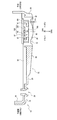
図1(A)は本実施形態の生体情報検出装置(生体情報測定装置)の一例を示す外観図である。この生体情報検出装置は時計タイプの脈拍計であり、本体部300と、被検体の手首400に生体情報検出装置を取り付けるためのバンド320、322(リストバンド)を有する。機器本体である本体部300には、各種の情報を表示する表示部310や、脈波センサー(検出部、透光部材等で構成されるセンサー)や、各種の処理を行う処理部などが設けられる。表示部310には、測定された脈拍数や時刻が表示されている。なお図1(A)では、手首400(又は腕)の周長方向を第1の方向DR1とし、手410から下腕420に向かう方向を第2の方向DR2としている。
1. Biological Information Detection Device FIG. 1A is an external view showing an example of a biological information detection device (biological information measurement device) of the present embodiment. This biological information detection device is a watch-type pulse meter, and has a
図1(B)は生体情報検出装置の詳細な構成例を示す外観図である。バンド320、322は、伸縮部330、332を介して本体部300に接続される。伸縮部330、332は、図1(A)の第1の方向DR1及び第2の方向DR2等に沿って変形可能となっている。バンド320の一端には連結部340が接続される。この連結部340は時計におけるバックルに相当するものであり、バックルの棒部が挿入されるバンド穴部は、逆側のバンド322に形成されている。
FIG. 1B is an external view illustrating a detailed configuration example of the biological information detection apparatus. The
図2(A)に示すように、連結部340は、バンド320に固定される固定部材342や、スライド部材344や、弾性部材であるバネ350、352を有する。そして図2(B)、図2(C)に示すように、スライド部材344は、固定部材342に対して、スライド方向DRSに沿ってスライド自在に取り付けられており、バネ350、352は、スライド時における引っ張り力を発生する。これらのバネ350、352や伸縮部330、332やバンド320、322等により、本実施形態の荷重機構が実現される。
As shown in FIG. 2A, the connecting
固定部材342には表示器343が設けられており、表示器343には、適正なスライド範囲を示すための目盛が付されている。具体的には、表示器343には、適正なスライド範囲(押圧範囲)を示す点P1、P2が付されている。そして、これらの点P1、P2の範囲内に、スライド部材344のバンド320側の端部が位置していれば、適正なスライド範囲(押圧範囲)内にあり、適切な引っ張り力が作用していることが保証される。ユーザーは、この適正なスライド範囲内になるように、バックルである連結部340の棒部を、バンド322のバンド穴部に挿入して、生体情報検出装置を手首に装着する。こうすることで、被検体に対する脈波センサー(透光部材の凸部)の押圧が、想定した適切な押圧になることが、ある程度保証されることになる。なお図1(A)〜図2(C)に示す生体情報検出装置の構造の詳細については、特開2012−90975号公報に開示されている。
The fixing
なお、図1(A)〜図2(C)では、生体情報検出装置が、手首に装着する時計タイプの脈拍計である場合を例にとり説明したが、本実施形態はこれに限定されない。例えば、本実施形態の生体情報検出装置は、手首以外の部位(例えば、指、上腕、胸等)に装着されて生体情報を検出(測定)するものであってもよい。また、生体情報検出装置の検出対象となる生体情報も、脈波(脈拍数)には限定されず、生体情報検出装置は、脈波以外の生体情報(例えば血液中の酸素飽和度、体温、心拍等)を検出する装置であってもよい。 In addition, although FIG. 1 (A)-FIG.2 (C) demonstrated taking the case where the biometric information detection apparatus was a timepiece type | mold pulse meter with which a wrist is mounted | worn, this embodiment is not limited to this. For example, the biological information detection apparatus of the present embodiment may be mounted on a part other than the wrist (for example, finger, upper arm, chest, etc.) and detect (measure) biological information. Further, the biological information to be detected by the biological information detection device is not limited to the pulse wave (pulse rate), and the biological information detection device can detect biological information other than the pulse wave (for example, oxygen saturation in the blood, body temperature, A device that detects a heartbeat or the like may be used.
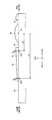
図3は、生体情報検出装置の本体部300の裏側に設けられる裏蓋部10の構成例を示す斜視図であり、図4は、図3のA−A’での断面図である。裏蓋部10は、カバー部材20と透光部材30により構成され、この裏蓋部10により、本体部300の裏側の筐体面22(裏面)が構成される。
FIG. 3 is a perspective view illustrating a configuration example of the
透光部材30は、生体情報検出装置の被検体に接触する筺体面22側に設けられ、被検体からの光を透過する。また透光部材30は、被検体の生体情報の測定時に、被検体に接触する。例えば透光部材30の凸部40が被検体に接触する。なお凸部40の表面形状は、曲面形状(球面形状)であることが望ましいが、これに限定されるものではなく、種々の形状を採用できる。また、透光部材30は被検体からの光の波長に対して透明であればよく、透明な材料を用いてもよいし、有色の材料を用いてもよい。
The
図4に示すように、カバー部材20は、透光部材30を覆うように形成される。透光部材30は透光性を有するが、カバー部材20は、透光性を有さず、非透光性の部材となっている。例えば、透光部材30は、透明な樹脂(プラスチック)で形成され、カバー部材20は、黒等の所定色の樹脂で形成される。なお、非透光性とは生体情報検出装置が検知可能な波長の光を透過しない材料のことを意味する。
As shown in FIG. 4, the
そして図3、図4に示すように、透光部材30は、その一部が、カバー部材20の開口から被検体側に露出しており、この露出部分に凸部40が形成されている。従って、生体情報の測定時に、この露出部分に形成された凸部40が、被検体(例えばユーザーの手首の肌)に接触することになる。図3、図4では、この露出部分に形成された凸部40により、生体情報検出装置の検出窓が構成されている。ここで、図4では、この検出窓以外の部分、つまりカバー部材20(押圧抑制部60)の裏側部分にも透光部材30が設けられている。但し本実施形態はこれに限定されず、検出窓の部分にだけ透光部材30を設けてもよい。
As shown in FIGS. 3 and 4, a part of the
なお図4に示すように、凸部40の周囲には、押圧変動等を抑制するための溝部42が設けられている。また、透光部材30において凸部40が設けられる側の面を第1の面とした場合に、透光部材30は、その第1の面の裏側の第2の面において凸部40に対応する位置に、凹部32を有している。また裏蓋部10には、裏蓋部10をネジ止めするためのねじ穴部24や、信号伝達や電源供給用の端子を接続するための端子穴部26なども設けられている。
In addition, as shown in FIG. 4, the
図3に示すように、生体情報検出装置の筺体面22(裏面)が、第1の方向DR1に沿った中心線CLにより第1の領域RG1と第2の領域RG2に区画される場合に、凸部40は、第1の領域RG1に設けられている。図1(A)に示すような手首に装着するタイプの生体情報検出装置を例にとれば、第1の領域RG1は手側(時計における3時方向)の領域であり、第2の領域RG2は下腕側(時計における9時方向)の領域である。このように透光部材30の凸部40は、筐体面22において手に近い側の第1の領域RG1に設けられる。こうすることで、腕の径変化が小さい場所に凸部40が配置されるようになるため、押圧変動等を抑制できる。
As shown in FIG. 3, when the body surface 22 (back surface) of the biological information detection device is partitioned into a first region RG1 and a second region RG2 by a center line CL along the first direction DR1, The
そして凸部40は、被検体の生体情報の測定時に被検体に接触して押圧(押圧力)を与える。具体的には、ユーザーが生体情報検出装置を手首に装着して、脈波等の生体情報を検出する際に、凸部40がユーザーの手首の肌に接触して押圧を与える。この押圧は、図1(A)〜図2(C)で説明した荷重機構による荷重により発生することになる。
And the
また生体情報検出装置の筐体面22には、凸部40が被検体(手首の肌)に与える押圧を抑制する押圧抑制部60が設けられている。図3、図4では、押圧抑制部60は、筐体面22において、透光部材30の凸部40を囲むように設けられている。そしてカバー部材20の面が押圧抑制部60として機能している。即ち、カバー部材20の面を土手形状に成型することで、押圧抑制部60が形成されている。図4に示すように、この押圧抑制部60の押圧抑制面は、凸部40の位置から第2の方向DR2(手首から下腕側への方向)に向かうにつれて低くなるように傾斜している。つまり、筐体面22に直交する方向DRHでの高さが、第2の方向DR2に向かうにつれて低くなるように傾斜している。
In addition, the
なお、図3、図4では、検出部130や凸部40(検出窓)が、筺体面22(裏面)の手側(3時方向)の第1の領域RG1に設けられているが、本実施形態はこれに限定されない。例えば検出部130や凸部40(検出窓)を、筺体面22の中央部の領域(中心線CLが通る領域)などに設け、その周辺に押圧抑制部60を設けてもよい。
3 and 4, the
図4に示すように、透光部材30の凸部40の下方には、検出部130が設けられている。ここで、上方は、方向DRHの方向であり、下方は、方向DRHの反対方向である。別の言い方をすれば、下方は、生体情報検出装置の本体部300の裏面(被検体に接触する側の面)から表面(被検体に接触しない側の面)へと向かう方向である。本実施形態における脈波センサーは、このような透光部材30や検出部130等で構成されるセンサーユニットである。
As shown in FIG. 4, a
検出部130は、受光部140と発光部150を有する。これらの受光部140と発光部150は、基板160に実装されている。受光部140は、被検体からの光(反射光、透過光等)を受光する。発光部150は、被検体に対して光を出射する。例えば発光部150が光を被検体に出射し、その光が被検体(血管)により反射されると、受光部140が、その反射光を受光して検出する。受光部140は、例えばフォトダイオード等の受光素子により実現できる。発光部150は、例えばLED等の発光素子により実現できる。例えば受光部140は、半導体の基板に形成されたPN接合のダイオード素子などにより実現できる。この場合に、受光角度を絞るための角度制限フィルターや受光素子に入射する光の波長を制限する波長制限フィルターを、このダイオード素子上に形成してもよい。
The
脈拍計を例にとると、発光部150からの光は、被検体の内部を進み、表皮、真皮及び皮下組織等で拡散又は散乱する。その後、この光は、血管(被検出部位)に到達し、反射される。この際に、光の一部は血管により吸収される。そして、脈拍の影響により血管での光の吸収率が変化し、反射光の光量も変化するため、受光部140がこの反射光を受光して、その光量の変化を検出することで、生体情報である脈拍数等を検出できるようになる。
Taking a pulse meter as an example, the light from the
なお図4では、検出部130として、受光部140と発光部150の両方が設けられているが、例えば受光部140だけを設けるようにしてもよい。この場合には、例えば受光部140は、被検体からの透過光を受光することになる。例えば被検体の裏側に設けられた発光部150からの光が被検体を透過した場合に、受光部140は、その透過光を受光して検出する。
In FIG. 4, both the
そして本実施形態では図4に示すように、絞り部80、82が設けられている。検出部130として受光部140が設けられている場合には、この絞り部80、82は、被検体と検出部130の間の光路において、被検体からの光を絞る。また、検出部130として発光部150が設けられている場合には、絞り部80、82は、被検体と検出部130の間の光路において、発光部150からの光を絞る。図4では、絞り部80、82は、透光部材30と検出部130の間に設けられている。但し、絞り部80、82を透光部材30と被検体との間や透光部材30内に設けてもよい。例えば絞り部80、82は透光部材30に近接して配置される。
And in this embodiment, as shown in FIG. 4, the aperture | diaphragm | squeeze
また図4では、受光部140と発光部150との間に遮光部100が設けられている。検出部130として、受光部140と発光部150の両方が設けられている場合には、この遮光部100は、例えば発光部150からの光が受光部140に直接入射されるのを遮光する。
In FIG. 4, the
2.透光部材の凸部、押圧抑制部
図5(A)に示すように本実施形態では、透光部材30は、被検体の生体情報の測定時に被検体に接触して押圧を与える凸部40を有している。また生体情報検出装置は、押圧抑制部60を有している。この押圧抑制部60は、生体情報検出装置の筺体面(被検体側の面)において凸部40を囲むように設けられ、凸部40が被検体に与える押圧を抑制する。
2. As shown in FIG. 5A, in the present embodiment, the
そして本実施形態では、例えば、生体情報検出装置の筺体面に直交する方向DRHでの凸部40の高さをHA(例えば凸部40の曲面形状の頂点の高さ)とし、押圧抑制部60の高さをHB(例えば最も高い場所での高さ)とし、高さHAから高さHBを減じた値(高さHAとHBの差)をΔhとした場合に、Δh=HA−HB>0の関係が成り立っている。例えば、凸部40は、押圧抑制部60の押圧抑制面から被検体側に、Δh>0となるように突出している。即ち、凸部40は、押圧抑制部60の押圧抑制面よりも、Δhの分だけ被検体側に突出している。
In the present embodiment, for example, the height of the
このように、Δh>0となる凸部40を設けることで、例えば静脈消失点を超えるための初期押圧を被検体に対して与えることが可能になる。また、凸部40が被検体に与える押圧を抑制するための押圧抑制部60を設けることで、生体情報検出装置により生体情報の測定を行う使用範囲において、押圧変動を最小限に抑えることが可能になり、ノイズ成分等の低減を図れる。また、Δh>0となるように凸部40が押圧抑制面から突出していれば、凸部40が被検体に接触して初期押圧を与えた後に、押圧抑制部60の押圧抑制面が被検体に接触して、凸部40が被検体に与える押圧を抑制できるようになる。ここで静脈消失点とは、被検体に凸部40を接触させ押圧を次第に強くした時に、脈波信号に重畳された静脈に起因する信号が消失、または脈波測定に影響しない程度に小さくなる点のことである。
As described above, by providing the
例えば図5(B)では、横軸は、図1(B)〜図2(C)で説明した荷重機構(バネ、伸縮部などの弾性部材や、バンド等で構成される機構)が発生する荷重を表しており、縦軸は、凸部40が被検体に与える押圧(血管にかかる圧力)を表している。そして凸部40の押圧を発生させる荷重機構による荷重に対する凸部40の押圧の変化量を押圧変化量としたとする。この押圧変化量は、荷重に対する押圧の変化特性の傾きに相当する。
For example, in FIG. 5B, the horizontal axis is generated by the load mechanism described in FIGS. 1B to 2C (a mechanism constituted by an elastic member such as a spring or a stretchable part, a band, or the like). The load represents the load, and the vertical axis represents the pressure (pressure applied to the blood vessel) that the
この場合に押圧抑制部60は、荷重機構の荷重が0〜FL1となる第1の荷重範囲RF1での押圧変化量VF1に対して、荷重機構の荷重がFL1よりも大きくなる第2の荷重範囲RF2での押圧変化量VF2が小さくなるように、凸部40が被検体に与える押圧を抑制する。即ち、初期押圧範囲である第1の荷重範囲RF1では、押圧変化量VF1を大きくする一方で、生体情報検出装置の使用範囲である第2の荷重範囲RF2では、押圧変化量VF2を小さくする。
In this case, the
つまり、第1の荷重範囲RF1では、押圧変化量VF1を大きくして、荷重に対する押圧の変化特性の傾きを大きくしている。このような変化特性の傾きが大きな押圧は、凸部40の飛び出し量に相当するΔhにより実現される。即ち、Δh>0となる凸部40を設けることで、荷重機構による荷重が少ない場合であっても、静脈消失点を超えるのに必要十分な初期押圧を、被検体に対して与えることが可能になる。
That is, in the first load range RF1, the pressure change amount VF1 is increased to increase the inclination of the pressure change characteristic with respect to the load. Such a pressing with a large gradient of the change characteristic is realized by Δh corresponding to the protrusion amount of the
一方、第2の荷重範囲RF2では、押圧変化量VF2を小さくして、荷重に対する押圧の変化特性の傾きを小さくしている。このような変化特性の傾きが小さな押圧は、押圧抑制部60による押圧抑制により実現される。即ち、凸部40が被検体に与える押圧を、押圧抑制部60が抑制することで、生体情報検出装置の使用範囲では、荷重の変動等があった場合にも、押圧の変動を最小限に抑えることが可能になる。これにより、ノイズ成分の低減等を図れる。
On the other hand, in the second load range RF2, the pressure change amount VF2 is reduced to reduce the inclination of the pressure change characteristic with respect to the load. Such a pressing with a small inclination of the change characteristic is realized by pressing suppression by the pressing suppressing
このように、最適化された押圧(例えば16kPa程度)が被検体に与えられるようにすることで、より高いM/N比(S/N比)の脈波検出信号を得ることが可能になる。即ち、脈波センサーの信号成分を増加させると共に、ノイズ成分を低減できる。ここでMは脈波検出信号の信号レベルを表し、Nはノイズレベルを表す。 In this way, it is possible to obtain a pulse wave detection signal having a higher M / N ratio (S / N ratio) by applying an optimized pressure (for example, about 16 kPa) to the subject. . That is, the signal component of the pulse wave sensor can be increased and the noise component can be reduced. Here, M represents the signal level of the pulse wave detection signal, and N represents the noise level.
また、脈波測定に使用する押圧の範囲を、第2の荷重範囲RF2に対応する範囲に設定することで、最小限の押圧変動(例えば±4kPa程度)に抑えることが可能になり、ノイズ成分を低減できる。 In addition, by setting the pressure range used for pulse wave measurement to a range corresponding to the second load range RF2, it is possible to suppress a minimum pressure fluctuation (for example, about ± 4 kPa), and a noise component Can be reduced.
また押圧抑制部60は、凸部40の周囲から外側に広がる押圧抑制面を有している。具体的には、図3、図4に示すように、押圧抑制部60は、凸部40の位置から第2の方向DR2側(手から下腕へと向かう方向側)に広がる押圧抑制面を有している。例えば、押圧抑制部60の押圧抑制面は、カバー部材20に形成された土手形状の部分により実現されている。
Further, the
また図3において、第1の方向DR1に直交する方向を第2の方向DR2とし、第2の方向DR2の反対方向を第3の方向DR3としたとする。この場合に、押圧抑制部60の押圧抑制面は、凸部40の周囲において、少なくとも第1の方向DR1、第2の方向DR2及び第3の方向DR3において連続した面となっている。つまり、凸部40の位置から少なくとも三方において面が連続している。具体的には、図3では、押圧抑制部60の押圧抑制面は、凸部40の全周囲(四方)に亘って連続した面になっている。つまり凸部40の全周囲に押圧抑制面が形成されている。このようにすれば、少なくとも第1、第2、第3の方向DR1、DR2、DR3に存在する押圧抑制面により、凸部40の押圧を抑制できるようになるため、均等で効率の良い押圧抑制が可能になる。
In FIG. 3, it is assumed that a direction orthogonal to the first direction DR1 is a second direction DR2, and a direction opposite to the second direction DR2 is a third direction DR3. In this case, the pressure suppression surface of the
また図3、図4では、凸部40を有する透光部材30は、筺体面22に対して固設されている。即ち、透光部材30は、筺体面22に対して固定して取り付けられているため、荷重機構により荷重が与えられたときにも、透光部材30は筺体面22(生体情報検出装置)に対して相対的に移動しないようになっている。例えば、ダンパー機構を設けて、荷重機構により荷重が与えられたときに、透光部材30が上下に移動するような可動構造とすることも可能であるが、図3、図4では、このような可動構造を採用していない。
3 and 4, the
また図3、図4では、押圧抑制部60は、絶縁部材により形成されている。即ち、押圧抑制部60は、導電部材(金属部材)などで形成される電極等ではなくて、凸部40の押圧抑制のために樹脂(プラスチック)等の絶縁性の材料で形成される絶縁部材となっている。
Moreover, in FIG. 3, FIG. 4, the
また図5(A)では、絞り部80、82(アパーチャー)や遮光部100を設けることで、光学的なノイズを低減し、脈波検出信号に乗るノイズ成分を更に低減している。例えば絞り部80、82は、C1、C2に示すように、この凸部40の周縁領域を通過する光を遮光している。こうすれば、C1、C2のように接触状態が不安定な場所での迷光を原因とする計測データの信頼性の低下等を抑制できる。
In FIG. 5A, by providing the
また、受光部140と発光部150との間の距離は、近ければ近いほど光学的な効率・性能が向上する。しかしながら、受光部140と発光部150の間の距離を近づけると、発光部150からの直接光が受光部140に入射されて性能が劣化する可能性が高まる。そこで図5(A)では、受光部140と発光部150の間に遮光部100を設け、発光部150からの直接光が受光部140に入射されるのを抑制している。こうすることで、直接光によるノイズ成分の重畳を抑制できるため、M/N比を更に向上できる。なお、絞り部80、82や遮光部100の少なくとも一方を設けない構成とする変形実施も可能である。
Further, the closer the distance between the
図6(A)〜図7(B)は押圧抑制部60による押圧抑制手法について更に詳細に説明する図である。
FIG. 6A to FIG. 7B are diagrams for explaining the pressing suppression method by the
例えば図6(A)では、生体情報検出装置の凸部40が被検体(手首等)に接触している。一方、押圧抑制部60の押圧抑制面62については被検体に接触していない。
For example, in FIG. 6A, the
図6(A)のように、荷重機構により荷重をかけながら、凸部40が被検体の表面(肌等)に接触すると、凸部40が表面にめり込み、図6(B)のD1に示すように押圧が急激に増加する。これは図5(B)で説明した初期押圧範囲に相当し、この初期押圧範囲では前述のように押圧変化量が大きくなる。つまり、凸部40を設けることで、荷重機構による荷重が少ない場合であっても、静脈消失点を超えるのに必要十分な初期押圧を、被検体に対して与えることが可能になる。
As shown in FIG. 6A, when the
そして図7(A)では、荷重機構による荷重が更に増加することで、凸部40のみならず押圧抑制部60の押圧抑制面62も被検体の表面(肌等)に接触している。このように押圧抑制面62が被検体の表面に接触することで、被検体との接触面積が増加する。これにより、図7(B)のD2に示すように、凸部40が被検体に与える押圧の増加が抑制される。即ち、図5(B)で説明した押圧変化量が、図7(B)のD2に示すように減少する。つまり、荷重に対する押圧の変化特性の傾きが小さくなる。従って、荷重機構による荷重が増加しても、凸部40の接触面が被検体に与える押圧(単位面積あたりの圧力)の増加度合いが弱まる。これにより、最適押圧範囲(図5(B)のRF2)において、押圧変化量(変化特性の傾き)を十分に小さくすることが可能になる。従って、生体情報検出装置の使用範囲では、荷重の変動等があった場合にも、押圧の変動を最小限に抑えることが可能になり、信号の品位を表すMN比を向上できる。
In FIG. 7A, the load by the load mechanism further increases, so that not only the
このように本実施形態では、Δh>0となる凸部40を設けることで、初期押圧範囲では、凸部40が被検体に与える押圧を急激に増加させる。一方、凸部40の周囲に押圧抑制部60(押圧抑制面)を設けることで、使用範囲では、押圧抑制部60による押圧抑制により、荷重に対する押圧の変化量である押圧変化量を減少させることで、押圧変動を低減する。
As described above, in the present embodiment, by providing the
3.凸部のΔh
凸部40の飛び出し量を表すΔhは、最適押圧を規定する重要なパラメーターとなる。即ち、静脈消失点を超えるための押圧を常に与えるためには、ある程度の飛び出し量が必要であり、Δhを大きな値にする必要がある。しかしながら、Δhが過大な値になってしまうと、脈波センサーの信号成分の低減や押圧変動の増加の要因となるおそれがある。
3. Δh of convex part
Δh representing the protruding amount of the
そこで、脈波センサーの信号成分を十分確保できる範囲、つまり最適押圧を与えることができる範囲で、最小のΔhを選択するようにする。即ち、最適押圧を与えることができる範囲であれば、Δhが小さいほど、ノイズ成分を低く抑えることができる。 Therefore, the minimum Δh is selected within a range where a signal component of the pulse wave sensor can be sufficiently secured, that is, within a range where the optimum pressure can be applied. That is, as long as Δh is smaller, the noise component can be kept lower as long as the optimum pressure can be applied.
例えば図8(A)は、ユーザーがグーパーの動作(GP)を行った場合における、ΔhとMN比(SN比)との関係を表す測定値の例である。また図8(B)は、ユーザーが走る動作(RUN)を行った場合における、ΔhとMN比との関係を表す測定値の例である。ここでMN比は、脈波センサーの信号成分(M)とノイズ成分(N)の比に相当するものである。 For example, FIG. 8A is an example of a measurement value representing the relationship between Δh and the MN ratio (SN ratio) when the user performs a grouper action (GP). FIG. 8B is an example of a measured value representing the relationship between Δh and the MN ratio when the user performs a running operation (RUN). Here, the MN ratio corresponds to the ratio of the signal component (M) and the noise component (N) of the pulse wave sensor.
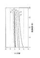
例えば、図8(A)、図8(B)では、Δhが0.01mmから0.05mmへと増えるにつれて、MN比が上昇する傾向にある。更に、Δhが0.05mmから0.15mm、0.15mmから0.25mmへと増えるにつれて、MN比が上昇する傾向にある。そして0.05mm〜0.25mmの範囲でのMN比の上昇率の方が、0.01mm〜0.05mmの範囲での上昇率よりも高くなる傾向にある。また0.15mm〜0.25mmの範囲でのMN比の上昇率の方が、0.05mm〜0.15mmの範囲での上昇率よりも高くなる傾向にある。 For example, in FIGS. 8A and 8B, the MN ratio tends to increase as Δh increases from 0.01 mm to 0.05 mm. Furthermore, as Δh increases from 0.05 mm to 0.15 mm and from 0.15 mm to 0.25 mm, the MN ratio tends to increase. And the increase rate of the MN ratio in the range of 0.05 mm to 0.25 mm tends to be higher than the increase rate in the range of 0.01 mm to 0.05 mm. Further, the increase rate of the MN ratio in the range of 0.15 mm to 0.25 mm tends to be higher than the increase rate in the range of 0.05 mm to 0.15 mm.
またΔhが0.5mmから0.35mmへと減少するにつれて、MN比が上昇する傾向にある。更に、Δhが0.35mmから0.25mmへと減少するにつれて、MN比が上昇する傾向にある。そして0.35mm〜0.25mmの範囲でのMN比の上昇率の方が、0.5mm〜0.35mmの範囲での上昇率よりも高くなる傾向にある。 Further, as Δh decreases from 0.5 mm to 0.35 mm, the MN ratio tends to increase. Furthermore, as Δh decreases from 0.35 mm to 0.25 mm, the MN ratio tends to increase. The rate of increase in MN ratio in the range of 0.35 mm to 0.25 mm tends to be higher than the rate of increase in the range of 0.5 mm to 0.35 mm.
以上より、Δhの範囲は、0.01mm≦Δh≦0.5mmであることが望ましく、更に好ましくは、0.05mm≦Δh≦0.35mmであることが望ましい。例えばΔh=0.25mm程度にすることで、MN比を最も大きくすることが可能になる。即ち、このようにΔhを小さな値にすることで、静脈消失点を超えるための最小限の押圧を被検体に与えながら、押圧変動等を要因とするノイズ成分の増加を抑制して、信号の品位を表すMN比を高めることが可能になる。 As described above, the range of Δh is desirably 0.01 mm ≦ Δh ≦ 0.5 mm, and more desirably 0.05 mm ≦ Δh ≦ 0.35 mm. For example, by making Δh = about 0.25 mm, the MN ratio can be maximized. That is, by setting Δh to a small value in this way, an increase in noise components caused by pressure fluctuations or the like is suppressed while giving the subject a minimum pressure for exceeding the venous vanishing point, and the signal It becomes possible to increase the MN ratio representing the quality.
図9は、凸部40による押圧とMN比及び脈拍数との関係を示す図である。図9に示すように、凸部40による押圧が、静脈消失点(静脈点)に対応する第1の押圧を超えると、静脈等によるノイズ成分(N)が減少するため、MN比が急激に高くなる。一方、凸部40による押圧が、動脈消失点(動脈点)に対応する第2の押圧を超えると、脈波信号成分(M)が減少するため、MN比が低下する。従って、静脈消失点に対応する第1の押圧と、動脈消失点に対応する第2の押圧との間の範囲内の押圧を与える必要がある。
FIG. 9 is a diagram showing the relationship between the pressing by the
この点、透光部材30に凸部40を設け、Δh>0とすれば、荷重機構による荷重がそれほど大きくなくても、静脈消失点と動脈消失点の間の範囲内の最適押圧(初期押圧)を被検体に対して効率的に与えることが可能になる。これにより、図9に示すような高いMN比の脈波検出信号を得ることができる。そして、最適押圧を与えることができれば、その範囲内においては、Δhはなるべく小さい方が、ノイズ成分の増加を抑えることができるため、望ましい。例えばΔhが大きくなりすぎると、脈波検出信号の成分(M)の低下や押圧変動の増加の要因となる。このため、Δhは、例えば0.01mm≦Δh≦0.5mm(0.05mm≦Δh≦0.35mm)の範囲に設定することが望ましい。
In this regard, when the
また本実施形態では、凸部40が、少なくとも被検体に接触する部分に曲面形状を有している。このように凸部40の表面形状を曲面形状にすれば、安定した接触状態で凸部により被検体に対して押圧を与えることが可能になる。
Moreover, in this embodiment, the
この場合に、凸部の曲面形状の曲率半径をRとすると、例えばR≧8mmであることが望ましい。このようにすれば、皮膚などの生体の表面との接触状態が安定する曲率半径の条件で、効率良く押圧を与えることが可能になる。 In this case, when the curvature radius of the curved surface shape of the convex portion is R, for example, it is desirable that R ≧ 8 mm. If it does in this way, it will become possible to give a pressure efficiently on the conditions of the curvature radius in which the contact state with the surface of living bodies, such as skin, is stabilized.
例えば図10、図11は、凸部40の曲面形状の曲率半径Rと脈DC値、Δ脈DC値(脈DC値の変化率)との関係を示す図である。R5、R6、R7、R8、R10、R12、R15の特性曲線は、各々、曲率半径Rが5mm、6mm、7mm、8mm、10mm、12mm、15mmである場合の特性曲線を示している。
For example, FIGS. 10 and 11 are diagrams illustrating the relationship between the curvature radius R of the curved surface shape of the
曲率半径Rが8mm(R8)になるまでは、曲率半径を大きくするほど、脈DC値(Δ脈DC値)は上昇する。一方、曲率半径Rが8mm以上になると、脈DC値の上昇は飽和する。別の言い方をすれば、曲率半径Rを8mm以上とすることで、脈DC値が安定するようになる。このように、皮膚との接触状態が安定する条件で適正な押圧(静脈消失点を越える押圧)を与えることができるような最小のRは、例えば8mmとなる。従って、曲率半径Rについては、R≧8mmの関係が成り立つことが望ましい。なお、後に詳述する絞り部82、84や遮光部100を設けることで、脈DC値を更に安定化させることが可能になる。
Until the curvature radius R reaches 8 mm (R8), the pulse DC value (Δ pulse DC value) increases as the curvature radius increases. On the other hand, when the curvature radius R is 8 mm or more, the increase of the pulse DC value is saturated. In other words, the pulse DC value is stabilized by setting the curvature radius R to 8 mm or more. Thus, the minimum R that can give an appropriate pressure (pressure exceeding the vanishing point) under the condition that the contact state with the skin is stable is, for example, 8 mm. Therefore, it is desirable that the relationship of R ≧ 8 mm holds for the curvature radius R. It should be noted that the pulse DC value can be further stabilized by providing the
4.押圧抑制部の詳細
次に、押圧抑制部60の詳細例について説明する。押圧抑制部60(土手構造)では、その押圧抑制面62の面積(被検体との接触面積)を大きくすることで、凸部40近傍にかかる押圧(接触圧)の変動を抑制できる。
4). Details of Press Suppression Unit Next, a detailed example of the
しかしながら、押圧抑制面62の面積を大きくしすぎたり、脈波センサーに対して押圧抑制面62の高さを高くしすぎると、凸部40近傍にかかる押圧が適正範囲に達しなくなり、脈波検出信号の品位が不十分になるおそれがあるという課題がある。
However, if the area of the
一方、押圧抑制面62の面積を小さくしたり高さを低くすると、押圧抑制の効果を十分に発揮できないという課題がある。押圧抑制の効果を発揮できないことは、押圧変動が大きくなって脈波検出信号のノイズ成分が増えてしまうことを意味する。
On the other hand, if the area of the
例えば図12(A)に示すように、手首付近の骨としては、親指側の橈骨と小指側の尺骨がある。そして、図12(B)に示すように生体情報検出装置の凸部40や押圧抑制部60の押圧抑制面62を手首の肌に接触させて、脈波等の生体情報を検出する際には、これらの橈骨や尺骨との干渉が生じないようにしながら、押圧抑制面62と手首の肌との接触面積を増加させることが望まれる。こうすることで、脈波センサーに対して押圧をかけやすくなると共に、押圧変動を効果的に抑制できるようになる。
For example, as shown in FIG. 12A, as the bone near the wrist, there are a rib on the thumb side and an ulna on the little finger side. Then, as shown in FIG. 12B, when the biological information such as a pulse wave is detected by bringing the
このために本実施形態の生体情報検出装置では、凸部40が被検体に与える押圧を抑制する押圧抑制部60を設けている。
For this reason, in the biological information detection apparatus of the present embodiment, a
そして図13に示すように、筺体面22が、第1の方向DR1に沿った中心線CLにより第1の領域RG1と第2の領域RG2に区画される場合に、凸部40(脈波センサー)は、第1の領域RG1に設けられる。
Then, as shown in FIG. 13, when the
例えば、第1の方向DR1に直交し凸部40から中心線CLへと向かう方向を第2の方向DR2としたとする。生体情報検出装置が被検体の手首に装着される場合には、この第2の方向DR2は、被検体の手から下腕へと向かう方向になる。このとき、凸部40は、被検体の手と下腕のうち手側に設けられる。即ち、手側の第1の領域RG1と下腕側の第2の領域RG2のうち、凸部40は、手側の第1の領域RG1に設けられる。
For example, it is assumed that the direction perpendicular to the first direction DR1 and going from the
更に、図13、図14に示すように、押圧抑制部60は、筺体面22に直交する方向からの平面視において、被検体の検出部位(手首又は腕等)の周長方向である第1の方向DR1に対して直交する第2の方向DR2に延びる押圧抑制面を有している。例えば押圧抑制部60は、凸部40の位置PS(凸部の最も高い位置)から第2の方向DR2に延びる押圧抑制面62を有する。即ち、押圧抑制面62が、凸部40の位置PSから、第2の方向DR2側(下腕側)に広がっている。
Furthermore, as shown in FIGS. 13 and 14, the
具体的には、押圧抑制面62は、凸部40の位置PSから中心線CLを越えて第2の方向DR2に延びる面となっている。例えば図13に示すように、押圧抑制面62(押圧抑制部)の長さをLSとし、筺体面22(本体部の裏面、裏蓋)の長さをLCとした場合にLS<LCとなっている。この場合に、例えば、(1/2)×LC≦LS≦(3/4)×LCとなることが望ましい。即ち、押圧抑制面62の第2の方向DR2側(9時側)での第1の端部ES1の位置は、ケース(裏蓋)の半分以上の位置であり、3/4以下の位置であることが望ましい。
Specifically, the
なお、長さLS、LCは、凸部40の位置PSにおける第2の方向DR2での押圧抑制面62(押圧抑制部)の長さである。具体的には、中心線CLに直交し、凸部40の位置PSを通る線をMLとした場合に、LSは、この線ML上での押圧抑制面62の長さであり、LCは、この線ML上での筺体面22(裏蓋)の長さである。
Note that the lengths LS and LC are the lengths of the pressure suppression surface 62 (press suppression portion) in the second direction DR2 at the position PS of the
また第2の方向DR2の反対方向を第3の方向DR3とし、凸部40の位置PSから、押圧抑制面62(押圧抑制部)の第2の方向DR2側の第1の端部ES1までの距離をLE1とし、凸部40の位置PSから、押圧抑制面62の第3の方向DR3側の第2の端部ES2までの距離をLE2としたとする。この場合に、図13ではLE1>LE2となっている。
Further, the direction opposite to the second direction DR2 is defined as a third direction DR3, and from the position PS of the
このようにすれば、LE2が小さいことから、凸部40は、押圧抑制面62の第2の端部ES2に寄った位置に配置されることになる。また、LE1が大きいことから、凸部40の位置から第1の端部ES1に向かって長い距離に亘って広がる押圧抑制面62を形成できるようになる。
In this way, since LE2 is small, the
更に、凸部40の位置PSにおける第1の方向DR1での押圧抑制面62の幅をWSとした場合に、WS<LE1となっている。
Further, when the width of the
このようにすれば、第1の方向DR1での押圧抑制面62の幅WSが小さくなり、第1の方向DR1が短手方向となり、第2の方向DR2が長手方向となるような押圧抑制面62を形成できるようになる。
By doing so, the width WS of the
なお、第1、第2の端部ES1、ES2は、例えば中心線CLに直交する線ML上での押圧抑制面62(押圧抑制部)の端部である。またLE1は、この線ML上での凸部40の位置PSから第1の端部ES1までの距離であり、LE2は、この線ML上での凸部40の位置PSから第2の端部ES2までの距離である。またWSは、凸部40の位置PSを通り中心線CLに平行な線上での押圧抑制面62(押圧抑制部)の幅である。
In addition, 1st, 2nd edge part ES1, ES2 is an edge part of the press suppression surface 62 (press suppression part) on the line ML orthogonal to the centerline CL, for example. LE1 is a distance from the position PS of the
例えば人間の腕は、手側から肘側に向かうにつれて太くなるテーパー形状となっており、手側に比べて肘側の方が、腕の径変化がより大きい。 For example, a human arm has a tapered shape that becomes thicker from the hand side toward the elbow side, and the arm diameter changes more on the elbow side than on the hand side.
この点、本実施形態では図13に示すように凸部40(脈波センサー)は、手側(左手装着の場合の3時方向)の領域である第1の領域RG1に設けられる。従って、生体情報検出装置を手首に装着にした際の座りが良く、装着感において優れている。また、上述のように腕はテーパー形状であるため、第1の領域RG1に凸部40を配置した方が、腕の径変化が少ないことから、押圧変動も少なく、結果として脈波検出信号に重畳するノイズも少なくなり、MN比を向上できる。
In this regard, in the present embodiment, as shown in FIG. 13, the convex portion 40 (pulse wave sensor) is provided in the first region RG1, which is a region on the hand side (3 o'clock direction in the case of wearing the left hand). Therefore, it is easy to sit down when the biological information detecting device is worn on the wrist, and the wearing feeling is excellent. In addition, since the arm has a tapered shape as described above, the change in the diameter of the arm is less when the
また、図5(B)で説明したように、生体情報検出装置により生体情報の測定を行う使用範囲では、荷重に対する押圧の変化特性における傾きを小さくして、押圧変動を最小限に抑えることが望まれる。このため、図7(B)のD2で説明したように、凸部40が被検体に与える押圧を、押圧抑制部60が抑制して、凸部40での押圧集中を低減している。そして、このような押圧抑制の効果を高めるためには、生体との接触面である押圧抑制面62の面積を、なるべく大きくする必要がある。
In addition, as described with reference to FIG. 5B, in the usage range in which the biological information is measured by the biological information detecting device, the inclination in the change characteristic of the pressure against the load can be reduced to minimize the pressure fluctuation. desired. For this reason, as explained in D2 of FIG. 7B, the pressing restraining
この場合に、図13の第1の方向DR1側に押圧抑制面62の接触面積を拡大しようとすると、押圧抑制面62の幅WSが大きくなる。しかしながら、図12(A)、図12(B)に示すように、手首の付近には橈骨と尺骨が存在するため、押圧抑制面62の幅WSが大きくなると、押圧抑制面62が橈骨、尺骨等と干渉してしまう。そして、このような干渉が生じると、図6(B)のD1で説明した、凸部40による初期押圧が抑制されてしまい、静脈消失点を超えるための初期押圧を被検体に対して与えることができなくなってしまう。
In this case, if the contact area of the
そこで図13では、押圧抑制面62は第2の方向DR2側に延びる面(広がる面)となっており、第2の方向DR2側に、生体との接触面積を拡大している。具体的には、押圧抑制面62は、第2の方向DR2を長軸方向とする、擬似的な楕円形状(トラック形状)となっている。即ち、凸部40の位置PSから第1の端部ES1までの距離LE1と、凸部40の位置PSから第2の端部ES2までの距離LE2との間には、上述のようにLE1>LE2の関係が成り立ち、押圧抑制面62の幅WSとLE1、LE2との間には、WS<LE1やWS<LE1+LE2の関係が成り立っている。
Therefore, in FIG. 13, the
このようにすれば、幅WSを小さくすることで押圧抑制面62と橈骨や尺骨との干渉を抑制して、凸部40による初期押圧を十分に確保(図6(B)のD1)しつつ、第2の方向DR2側に押圧抑制面62の接触面積を拡大することで、凸部40の押圧を抑制(図7(B)のD2)して、使用範囲での押圧変動を最小限に抑えることが可能になる。即ち、凸部40による十分な初期押圧の確保と、使用範囲での押圧変動の抑制を両立して実現できるようになり、ノイズ成分を低減して十分なMN比を確保することが可能になる。
In this way, by reducing the width WS, the interference between the
この場合、接触面積を確保するために押圧抑制面62の第2の方向DR2での長さを長くしすぎると、凸部40から遠くの場所(例えば下腕側の第1の端部ES1)における筋肉、腱の動きや腕の径変化等が、凸部40(脈波センサー)の部分にまで伝わってしまう。これにより、凸部40において押圧変動が発生し、結果として体動ノイズがより大きく重畳してしまう。
In this case, if the length of the
そこで図13では、押圧抑制面62は、凸部40の位置から中心線CLを越えて第2の方向DR2に延びる面となっているものの、第2の方向DR2での押圧抑制面62の長さLSと筺体面22の長さLCの間には、LS<LCの関係が成り立っている。更に望ましくは、(1/2)×LC≦LS≦(3/4)×LCの関係を成り立たせる。このように押圧抑制面62の第2の方向DR2での長さLSを、ある程度の長さに抑えれば、凸部40から遠くの場所における筋肉、腱等の動きが凸部40の部分にまで伝わって体動ノイズが重畳してしまう事態を、効果的に抑制できる。
Therefore, in FIG. 13, the
また本実施形態では図14に示すように、押圧抑制面62の第2の方向DR2側への延長部分に対して、筺体面22(ケース底面)を基準に傾斜をつけている。
Further, in the present embodiment, as shown in FIG. 14, the extension portion of the
例えば図14において、凸部40の位置PSから第2の方向DR2(広義には所定方向)において第1の距離LP1だけ離れた位置を第1の位置PP1とし、凸部40の位置PSから第2の方向DR2(所定方向)において第1の距離LP1よりも長い第2の距離LP2だけ離れた位置を第2の位置PP2とする。これらの第1、第2の位置PP1、PP2は、例えば図13において第2の方向DR2(所定方向)に沿った線ML上の位置である。また第1の位置PP1における、筺体面22に直交する方向DRHでの押圧抑制面62の高さをHS1とし、第2の位置PP2における、方向DRHでの押圧抑制面62の高さをHS2としたとする。すると図14ではHS1>HS2の関係が成り立っている。具体的には、押圧抑制面62は、筺体面22に直交する方向DRHでの高さが、凸部40の位置PSから第2の方向DR2(所定方向)へと向かうにつれて低くなるように傾斜している。例えば3度〜6度程度の範囲の角度の傾斜をつけている。なお、図14のように高さが滑らかに変化する傾斜にはせずに、例えばステップ状に高さが変化する傾斜にするなどの種々の変形実施が可能である。
For example, in FIG. 14, a position that is separated from the position PS of the
このような傾斜をつけることで、例えば押圧抑制面62の第2の方向DR2側(9時側)の第1の端部ES1付近での押圧集中を抑制できる。これにより、凸部40への荷重をかけやすくなり、適正押圧を得ることが容易になる。例えば前述したように腕はテーパー形状となっている。従って、例えば第2の方向DR2側の第1の端部ES1が高くなっていると、図1(A)、図1(B)のバンド320、322をきつく締めて、凸部40に荷重をかけようとしても、この第1の端部ES1において荷重を受け止めてしまう傾向が強くなってしまう。従って、バンド320、322をいくらきつく締めても、凸部40(脈波センサー)に必要な荷重をかけることができなくなり、適正な押圧を得るのが困難になるという問題がある。この点、図14のように押圧抑制面62に対して傾斜をつければ、このような問題を解消できるようになる。
By giving such an inclination, for example, the pressing concentration in the vicinity of the first end ES1 on the second direction DR2 side (9 o'clock side) of the pressing suppressing
図15、図16は、押圧抑制面62の形状とMN比、押圧変動との関係を示す図である。例えば図15、図16は、ユーザーがグーパーの動作(GP)や走る動作(RUN)を行った際において、押圧抑制面62が例えば真円の形状である場合と、本実施形態のような楕円形状(疑似楕円形状、トラック形状)である場合との、MN比や押圧変動の比較図となっている。
15 and 16 are diagrams showing the relationship between the shape of the
図15、図16に示すように、大多数のユーザーでは、図13に示すような9時側に拡大した楕円形状の押圧抑制面62の方が、真円形状である場合に比べて、MN比が高くなると共に押圧変動も小さくなる。
As shown in FIGS. 15 and 16, in the majority of users, the oval-shaped
例えば押圧抑制面62が真円形状である場合には、橈骨や尺骨に接触面が接触して初期押圧を十分にかけられなくなったり、接触面の面積が小さくなって、使用範囲において凸部40の押圧を十分に抑制できなくなるおそれがある。
For example, when the
この点、本実施形態のように、第2の方向DR2側(9時側)に接触面を拡大することで、凸部40での荷重変動が小さくなり、押圧変動が小さくなる。結果として、脈波検出信号の品位を表すMN比(脈成分のパワースペクトルの大きさ/ノイズ成分のパワースペクトルの大きさ)が高くなる。
In this regard, as in the present embodiment, by enlarging the contact surface in the second direction DR2 side (9 o'clock side), the load fluctuation at the
図17(A)〜図17(C)は押圧抑制部60の変形例である。図17(A)は変形例を示す斜視図であり、図17(B)は上面図であり、図17(C)は図17(B)のC−C’での断面図である。
FIG. 17A to FIG. 17C are modified examples of the
この変形例では、透光部材30に対して凸部40が設けられているが、この凸部40は、透光部材30の中心位置からずれた位置に設けられている。また、凸部40の周囲には、溝部42を介して、押圧抑制部60が設けられているが、押圧抑制部60(押圧抑制面)の形状・構造は、図13、図14とは異なった形状・構造となっている。例えば図17(B)の上面図において、押圧抑制部60は、透光部材30や凸部40を囲むドーナツ形状(同心円形状)となっている。
In this modified example, the
また、この変形例では図17(C)に示すように、図14と同様に、押圧抑制面62は、筺体面に直交する方向での高さが、凸部40の位置から外側へと向かうにつれて低くなるように傾斜している。また、凸部40の高さをHAとし、押圧抑制部60の高さをHB(最も高い場所での高さ)とした場合に、Δh=HA−HB>0の関係が成り立っている。
Further, in this modified example, as shown in FIG. 17C, as in FIG. 14, the
このように押圧抑制部60の形状・構造としては種々の変形実施が可能である。例えば生体情報検出装置が手首以外の部位に装着されるものである場合には、必ずしも、図13のように手側の第1の領域RG1に凸部40が設けられている必要はない。
As described above, various modifications can be made to the shape and structure of the
また、例えば図17(C)のような傾斜等がつけられている場合には、押圧抑制面62は、凸部40の位置から第2の方向DR2側に広がるような面でなくてもよい。即ち、傾斜がつけられる方向である所定方向は、第2の方向DR2には限定されない。また押圧抑制面62は、凸部40の周囲において、少なくとも三方(第1、第2、第3方向DR1、DR2、DR3)において連続した面であればよく、全周囲(四方)に亘って連続した面である必要は必ずしもない。
Further, for example, when an inclination or the like as shown in FIG. 17C is provided, the
また図4、図13、図14等では、カバー部材20の面を土手形状に成型することで、押圧抑制部60を形成しているが、本実施形態はこれに限定されない。例えば、押圧抑制部60を、カバー部材20とは別の部材で形成して筺体面22に配置するなどの種々の変形実施が可能である。
Moreover, in FIG.4, FIG.13, FIG.14 etc., although the
5.透光部材
次に透光部材30の形状・構造の種々の例について説明する。
5. Translucent Member Next, various examples of the shape and structure of the
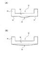
図18(A)に示すように、透光部材30は、凸部40とボディー部50を有する。凸部40は、透光部材30のうち、被検体側に少なくとも一部が突出(露出)する部分であり、図18(A)では凸部40は曲面形状となっている。このように人体の皮膚に接触する透光部材30の接触面を、曲面形状の凸部40で構成することで、皮膚表面に対する透光部材30の密着度が向上するため、皮膚表面からの反射光量や外乱光等のノイズ光の侵入を防止できる。なお凸部40を曲面以外の形状としてもよい。
As shown in FIG. 18A, the
また、ボディー部50は、凸部40に対して、被検体側と反対方向側(検出部側)である下方(図面では上方)に設けられる。このボディー部50は、透光部材30の本体部分であり、このボディー部50を本体部分として、被検体と接触するための凸部40が形成される。
Further, the
透光部材30(ボディー部50)において凸部40が形成されている側の面を第1の面とし、第1の面の裏側の面を第2の面とする。すると図18(A)では、第2の面において凸部40に対応する位置(凸部40の裏側)には、凹部32が形成されている。このような凹部32を形成することで、図4の受光部140への入射光や発光部150からの出射光が透光部材30を通る際の光路を短くできる。即ち透光部材30の実質的な厚さを薄くすることができ、さらに受光部140や発光部150をより被検体の表面に近づけることができる。これにより、光の透過率が高くなり、信号品位を向上できる。
In the translucent member 30 (body part 50), the surface on which the
また図18(A)では、凸部40の周囲に溝部42が設けられている。この溝部42の底面の高さは、押圧抑制面62の高さ(最も高い端部での高さ)よりも低くなっており、溝部42の底面は、押圧抑制面62よりも下方(検出部側)の面となる。
In FIG. 18A, a
例えば、樹脂やガラス等で形成される硬い素材の透光部材30の接触面に対して、肌のように相対的に柔らかいものを接触させると、透光部材30の周縁部(外周部)の付近においては、肌と接触していない領域や、接触圧の弱い領域が生じる。従って、例えば凸部40の周囲に、図18(A)に示すような溝部42を設けずに、平坦部にすると、この平坦部が肌と接触しなかったり、弱い接触状態になるなどして、接触状態が動的に変化してしまう。そして、このような接触状態の動的な変化が原因で、光学的に光の強弱が発生しやすくなり、そのような光が受光部140に入射すれば、脈成分とは相関の無いノイズとなってしまう。
For example, when a relatively soft material such as skin is brought into contact with the contact surface of the
この点、図18(A)のような溝部42を設ければ、このように接触状態が動的に変化する領域が発生してしまうのを、効果的に防止できるようになるため、信号品位の向上等を図れるようになる。
In this regard, if the
また図18(B)のE1に示すように、ボディー部50は、凸部40の位置から、筺体面のカバー部材20の下方に延在形成されている。そして押圧抑制面62は、このカバー部材20の面により形成されている。
Further, as shown by E1 in FIG. 18B, the
即ち、図3、図4のように、生体情報検出装置の裏蓋を、透光部材30と、この透光部材30を覆うように設けられたカバー部材20とにより形成する。そして、透光部材30のうち、カバー部材20により覆われていない部分が、脈波センサーの検出窓となり、この検出窓に凸部40が形成されている。
That is, as shown in FIGS. 3 and 4, the back cover of the biological information detecting device is formed by the
このような構造とすれば、防水性能等を向上することが可能になり、例えば水等の液体が生体情報検出装置の内部に侵入して、検出部130等の故障の要因となる事態を抑止できるようになる。即ち、ボディー部50を延在形成せずに、例えば図18(B)のE2に示す部分等でボディー部50が切断される構造であると、その切断部分に水等の液体が浸入して、防水性能が低下するおそれがある。
With such a structure, it becomes possible to improve waterproofing performance and the like, for example, a liquid such as water enters the inside of the biological information detection device and suppresses a situation that causes a failure of the
この点、図18(B)のE1では、ボディー部50がカバー部材20の下方にまで延在形成されているため、E2に示す部分には液体の侵入経路がなく、防水性能等を格段に向上できる。
In this regard, in E1 of FIG. 18B, since the
そして図18(B)では、このように延在形成した透光部材30のボディー部50を覆うカバー部材20を有効活用して、押圧抑制面62を形成している。こうすることで、防水性能等の向上と、押圧抑制による信号品位の向上とを両立して実現することが可能になる。
In FIG. 18B, the
なお、透光部材30の形状・構造としては種々の変形実施が可能である。例えば図19(A)の透光部材30では、図18(A)のような溝部42は設けられておらず、平坦部52だけが設けられている。この平坦部52の高さは、押圧抑制面62の高さ(端部での高さ)と例えば同じ高さになる。
Various modifications can be made to the shape and structure of the
また図19(B)では、図19(A)の平坦部52は設けられておらず、被検体との接触面(露出部分)は、全て曲面形状の凸部40により形成されている。即ち、図19(A)では、接触面は、曲面形状の凸部40と平坦部52とにより形成されていたが、図19(B)では、接触面は全て曲面形状の凸部40のみにより形成されている。このように透光部材30の形状・構造としては種々の変形実施が可能である。なお、図19(A)、図19(B)では共に、凸部40の裏側の面には凹部32が形成されている。
In FIG. 19B, the
6.絞り部、遮光部
さて、本実施形態のような生体情報検出装置では、透光部材30において、被検体である肌に接触する面は有限面積の接触面となっている。そして本実施形態では、例えば樹脂やガラス等で形成される硬い素材の透光部材30の有限面積の接触面に対して、肌のように相対的に柔らかいものを接触させている。すると、弾性力学の観点で見ると、透光部材30の周縁部(外周部)の付近においては、肌と接触していない領域や、接触圧の弱い領域が生じる。また生体情報検出装置の機器に外力が加えられて、機器にモーメントが発生するときなども、接触面の周縁部の付近の領域は、最も浮きやすい。
6). In the living body information detection apparatus as in the present embodiment, the surface of the
このような領域を介して、発光部150、肌、受光部140の間を通過する光には、動的な接触状態の変化に起因して、光学的に光の強弱が発生しやすい。そして、そのような光が受光部140に入射すれば、脈成分とは相関の無いノイズとなってしまう。
The light passing between the
また、静的な接触状態であっても、信号品位の低下は起こり得る。肌にきちんと接触していなければ、発光部150を起源としない外光が、受光部140に入射することがある。一方、過大な接触圧となっている場合には、皮下の血管を潰してしまうことにより、この領域を通過した光には、拍動成分が入りにくくなる。
Even in a static contact state, signal quality can be degraded. If the skin is not properly in contact, external light that does not originate from the
このようなノイズが大きく重畳するほど、脈波検出信号の信号品位は低下し、脈拍計測などの様々な生体計測において、計測データの信頼性が低下してしまう。 The greater the noise is superimposed, the lower the signal quality of the pulse wave detection signal, and the reliability of measurement data decreases in various biological measurements such as pulse measurement.
例えば図20(A)は、透光部材30の凸部40(接触面)が、被検体である肌2に与える押圧が小さい場合を示し、図20(B)は当該押圧が大きい場合を示している。図20(A)、図20(B)のA1、A2に示す場所に着目すると、押圧の変化により、肌2と凸部40との間の接触状態が変化している。例えば図20(A)では、A1、A2の場所において肌2と凸部40が非接触状態又は弱い接触状態になっているが、図20(B)では接触状態になっている。従って、発光部150から出射されて受光部140に戻ってくる光の強弱などが、図20(A)と図20(B)とで変化してしまい、計測データの信頼性が低下する。なお、図20(A)、図20(B)は図3に示す生体情報検出装置のA−A’断面図の凹部32周辺を拡大した図と解釈してもよいし、方向DRHに対して鉛直方向から凹部32周辺の構成部品を投影した投影図又は配置図と解釈してもよい。本実施形態では、図20(A)、図20(B)の類似図を用いて説明を行うが、いずれの図も同様に解釈できるものとする。
For example, FIG. 20A shows a case where the convex portion 40 (contact surface) of the
例えば図21(A)、図21(B)はヘルツの弾性接触理論を説明する図である。Eは肌のヤング率、vは肌のポアソン比、Fは加える力の最大値、rは球面半径、αは接触円面の半径、σは変位である。これらのパラメーターに所定値を代入し、ヘルツの弾性接触理論に基づいて、接触面中心からの距離に対する押圧を計算すると、例えば図21(B)のような結果が得られる。図21(B)に示すように、接触面中心から距離が離れると、押圧が低下し、例えばB1、B2に示す部分では、急激な低下になる。従って、図20(A)、図20(B)のA1、A2に示す場所では、荷重の微少な変化によって、接触面での押圧が急激に変化してしまい、計測データの信頼性が著しく低下する。 For example, FIGS. 21A and 21B are diagrams for explaining Hertz's elastic contact theory. E is the skin Young's modulus, v is the skin Poisson's ratio, F is the maximum force applied, r is the spherical radius, α is the radius of the contact circle, and σ is the displacement. By substituting predetermined values for these parameters and calculating the pressure against the distance from the center of the contact surface based on Hertz's elastic contact theory, a result such as that shown in FIG. 21B is obtained. As shown in FIG. 21 (B), when the distance is away from the center of the contact surface, the pressure is reduced. For example, the portions shown in B1 and B2 are drastically reduced. Therefore, at the locations indicated by A1 and A2 in FIGS. 20A and 20B, the pressure on the contact surface changes abruptly due to slight changes in the load, and the reliability of the measurement data is significantly reduced. To do.
例えば図20(A)、図20(B)では、人体の皮膚に接触する透光部材30の接触面を、曲面形状の凸形状(凸部)で構成している。このようにすることで、皮膚表面に対する透光部材30の密着度が向上するため、皮膚表面からの反射光量や外乱光等のノイズ光の侵入を防止できる。
For example, in FIG. 20 (A) and FIG. 20 (B), the contact surface of the
しかしながら、図21(A)、図21(B)から明らかなように、凸形状の周縁部(外周部)では中心部に対して相対的に肌との接触圧が低下する。 However, as is clear from FIG. 21A and FIG. 21B, the contact pressure with the skin is relatively lowered with respect to the central portion at the convex peripheral portion (outer peripheral portion).
この場合に、中心部の接触圧で最適化すると、周縁部の接触圧は最適範囲未満となる。一方、周縁部の接触圧で最適化すると、中心部の接触圧が最適範囲に対し過剰となる。 In this case, if the contact pressure at the central portion is optimized, the contact pressure at the peripheral portion is less than the optimum range. On the other hand, if the contact pressure at the peripheral edge is optimized, the contact pressure at the center is excessive with respect to the optimum range.
接触圧が最適範囲未満の場合は、機器の揺れにより脈波センサーが肌と接触したり離れたりするケースや、接触したままとしても脈波センサーが静脈を潰しきれていないことにより、脈波検出信号に体動ノイズが重畳する。このノイズ成分を低減すれば、より高いM/N比(S/N比)の脈波検出信号を得ることが可能になる。 When the contact pressure is less than the optimum range, the pulse wave sensor detects if the pulse wave sensor comes in contact with or away from the skin due to the shaking of the device, or the pulse wave sensor does not crush the veins even if it remains in contact. Body motion noise is superimposed on the signal. If this noise component is reduced, a pulse wave detection signal having a higher M / N ratio (S / N ratio) can be obtained.
以上のような課題を解決するために、図4、図22(A)、図22(B)に示すように、本実施形態では、絞り部80、82(アパーチャー)を設けている。絞り部80、82は、被検体と検出部130の間の光路において、被検体からの光を絞る。また図4等では、検出部130は、被検体に対して光を出射する発光部150を有しており、透光部材30は、発光部150からの光を透過する。そして絞り部80、82は、被検体と検出部130の間の光路において、発光部150からの光を絞る。なおリフレクター152は、発光部150が発光する光を反射して光の利用効率を高めるためのものである。
In order to solve the problems as described above, as shown in FIGS. 4, 22A, and 22B, in this embodiment,
このように本実施形態では、図22(A)、図22(B)のA1、A2に示す場所等での光(迷光)が検出されないように、絞り部80、82を設けて、光を絞っている。例えば、最適押圧化された透光部材30の透光領域の中心部(例えば凸部の頂点)を通過する光は、できるだけ遮断せずに透過させる一方で、透光部材30の透光領域(例えば凸部)の周縁部の付近を介した光は遮断する。例えば図22(A)、図22(B)では、絞り部80を設けることで、周縁部であるA1に示す場所での光が受光部140に入射されないようになる。また、絞り部82を設けることで、発光部150からの光が、A2に示す場所に対して出射されないようになる。つまり本実施形態では、押圧(荷重)の変化によって接触状態が変化する場所での光を絞っている。このようにすれば、図22(A)、図22(B)に示すようにA1、A2に示す場所で接触状態が変化した場合にも、A1、A2に示す場所での光の状態が受光結果に影響を及ばさなくなる。従って、計測データの信頼性等を向上できるようになる。
As described above, in the present embodiment, the
更に図4、図22(A)、図22(B)等では、受光部140と発光部150の間に遮光部100(遮光壁)を設けている。この遮光部100は、例えば、筺体面22(図3、図4参照)に直交する方向DRHに延在形成される遮光壁である。具体的には、例えば受光部140の中心位置と発光部150の中心位置を結ぶ線分に対して交差(直交)する方向に沿った壁面を有する遮光部100が設けられる。このような遮光部100を設けることで、発光部150からの直接光が受光部140に入射されるのが抑止されて、計測データの信頼性等を更に向上できるようになる。
Further, in FIGS. 4, 22 </ b> A, 22 </ b> B, etc., a light shielding unit 100 (light shielding wall) is provided between the
即ち、受光部140と発光部150との間の距離は、近ければ近いほど光学的な効率・性能が向上する。例えば光学的な効率・性能は距離の二乗に反比例して劣化する。従って、できる限り受光部140と発光部150の間の距離を近づけることが望ましい。
That is, the closer the distance between the
しかしながら、受光部140と発光部150の間の距離を近づけると、発光部150からの直接光が受光部140に入射されて性能が劣化する可能性が高まる。
However, when the distance between the
そこで、受光部140と発光部150の間に遮光部100を設け、発光部150からの直接光が受光部140に入射されるのを抑止する。即ち本実施形態では、前述したように、被検体との接触面の接触状態が不安定になる経路からの光学的な悪影響を除去するために、絞り部80、82を設けている。一方、発光部150の直接光による悪影響については遮光部100により除去する。こうすれば、被検体との接触面の接触状態の変動によるノイズを除去する絞り部80、82と、発光部150の直接光を除去する遮光部100とにより、光電型の脈波センサーの光学的な安定性を確保することが可能になる。なお遮光部100については、これを設けない構成とすることも可能である。
Therefore, the
なお、図4、図22(A)、図22(B)等では、絞り部80、82が、透光部材30と検出部130(受光部140、発光部150)の間に設けられている。例えば、絞り部80、82は、透光部材30や検出部130から離れた位置に配置設定されている。このように、透光部材30と検出部130の間に絞り部80、82を配置すれば、被検体と検出部130の間の光路上において、絞り部80、82により迷光を効果的に遮って、この迷光によるノイズが計測データに重畳されてしまう事態を効果的に抑制できる。但し、絞り部80、82の配置形成手法は、これに限定されず、種々の変形実施が可能であり、絞り部80、82を、透光部材30と被検体との間又は透光部材30内に設けてもよい。
In FIGS. 4, 22 </ b> A, 22 </ b> B, and the like, the
例えば図23(A)では、絞り部80、82は、透光部材30と検出部130の間に設けられているものの、透光部材30に対して密着するように絞り部80、82が配置形成されている。また図23(B)では、透光部材30内(材質中)に絞り部80、82が配置形成されている。また図23(C)では、被検体と透光部材30の間に絞り部80、82が配置形成されている。このように絞り部80、82の配置形成手法としては種々の態様を想定できる。
For example, in FIG. 23A, the
また絞り部80、82の製造手法も、図4、図22(A)、図22(B)等のように透光部材30等と別体に形成する手法に限定されず、種々の手法を採用できる。例えば図23(A)、図23(C)のように透光部材30に密着するように絞り部80、82を形成する場合には、塗装、蒸着又は印刷などの手法により絞り部80、82を形成すればよい。或いは図23(B)のように透光部材30の中に絞り部80、82を形成する場合には、例えばインサート成型などの手法により絞り部80、82を形成すればよい。
In addition, the manufacturing method of the
なお、本実施形態では、絞り部80、82と遮光部100とを遮光用部材78として一体形成してもよい。即ち、絞り部80、82と遮光部100(遮光壁)とを一体構造とする。図24は、このように一体形成された遮光用部材78の例を示す斜視図である。
In the present embodiment, the
図24に示すように、遮光用部材78には、受光部側に設けられた絞り部80(第1の絞り部)と、発光部側に設けられた絞り部82(第2の絞り部)とが形成されている。そして受光部側の絞り部80に対応して、受光部側の絞りの開口部81が形成され、発光部側の絞り部82に対応して、発光部側の絞りの開口部83が形成されている。絞り部80、82との間には、絞り部80、82と一体的に遮光部100が形成されている。例えば、遮光用部材78は、一端側に底部が形成され他端側が開口する有底筒部の形状となっており、この有底筒部の底部が絞り部80、82として形成される。そして底部である絞り部80、82に対して、アパーチャーとして機能する開口部81、83が形成されている。また有底筒部の他端側の開口の領域を2分割(分断)するように、遮光部100が形成されている。
As shown in FIG. 24, the
遮光部100は、図24に示すように、その中心部102において肉厚が細くなっている。こうすることで、受光部140と発光部150の距離を、より近づけることが可能になり、光学的な効率・性能を向上できる。
As shown in FIG. 24, the light-shielding
また、生体情報検出装置の筺体面22(図3、図4参照)に直交する方向DRH(図5(A)参照)での遮光部100の高さをH1とし、絞り部80、82の検出部130側の面である下面の高さをH2としたとする。これらの高さH1、H2は基準面(例えば基板160)からの高さである。この場合に、H1>H2の関係が成り立っている。即ち、遮光部100は、絞り部80、82の下面よりも高い位置まで延在形成された遮光壁となっている。こうすることで、発光部150からの光が、絞り部80、82等に反射して、受光部140に入射されてしまう事態を抑制できる。即ち、発光部150の直接反射光の影響を除去することが可能になり、測定データの信頼性の低下等を抑制できる。
Further, the height of the light-shielding
また、遮光用部材78は、受光部140及び発光部150が実装される基板160の上方(方向DRHの方向)から、基板160に向かって取り付けられる(図5(A)参照)。即ち、遮光用部材78の有底筒部形状の他端側の開口の領域に対して、受光部140及び発光部150が実装される基板160が挿入されるように、取り付けられる。そして遮光用部材78には、突起部86、88が形成されており、この突起部86、88が、基板160に形成された穴部に嵌合することで、遮光用部材78が基板160に対して固定される。これにより、例えば透光部材30の裏側の凹部32に対応する位置に、絞り部80、82、遮光部100、受光部140、発光部150が配置されるようになる。この場合に凹部32の部分では、透光部材30の肉厚が薄くなっている。従って、受光部140に入射される光や、発光部150から出射される光についての、透光部材30での通過距離である光路の長さを短くできる。従って、これらの光の透光部材30での減衰が低減され、透過光量を向上できる。
In addition, the
なお、絞り部80、82、遮光部100には、脈波センサーの光学的な効率・性能を向上するための加工処理等を施すことが望ましい。例えば、絞り部80、82、遮光部100の表面(壁面)を荒くする加工処理を行って、光の反射率を抑制する。或いは、絞り部80、82、遮光部100の表面をモスアイ構造にする。例えば数十〜数百nm周期の凹凸構造を表面に形成して、反射防止構造とする。或いは、絞り部80、82、遮光部100の表面の色を、黒色等の所定色にして、光の乱反射を防ぐようにする。このようにすれば、絞り部80、82、遮光部100での反射光が迷光となって、計測データのノイズ成分となってしまう事態を効果的に抑制できる。
In addition, it is desirable that the
さて、前述したように、脈波センサーの光学的な効率・性能を向上するためには、受光部140と発光部150との間の距離を最小化することが望ましい。このため、遮光部100をできるだけ薄い壁厚構造にする必要がある。特に、図24の遮光部100の中心部102(受光部140の中心位置と発光部150の中心位置を結ぶ線と交わる領域)において、遮光部100の壁厚を薄くする。
As described above, in order to improve the optical efficiency and performance of the pulse wave sensor, it is desirable to minimize the distance between the
しかしながら、このように薄い壁厚の遮光部100の単体構造では、強度が不足してしまう。例えば脈拍計が使用される走行時や自転車搭乗時には、強い衝撃(例えば10G程度)が機器に加わるため、それらの衝撃に対応できる強度が必要となる。
However, the strength of the single-piece structure of the light-shielding
そこで図24では、絞り部80、82と遮光部100を一体構造とする手法を採用している。即ち、絞り部80、82と遮光部100の各々を単体の部材で実現するのではなく、図24に示すように絞り部80、82と遮光部100が一体形成された遮光用部材78を用いる。このような一体形成された遮光用部材78であれば、遮光部100の壁厚が薄くても、衝撃に耐えうる強度を確保することが可能になる。
Therefore, in FIG. 24, a method is adopted in which the
また、絞り部80、82と遮光部100は共に、光学的な安定化という目的の点で一致しているため、材料の共通化等が容易である。例えば、絞り部80、82と遮光部100の表面の色を、乱反射の生じない黒色に設定することなども容易となる。
In addition, since the
また絞り部80、82と遮光部100を一体化することで、部品組み立て時の組立性が向上し、コスト低減に寄与する。例えば、透光部材30の凹部32に遮光用部材78を挿入し、遮光用部材78の突起部86、88を、受光部140、発光部150が実装された基板160に嵌合させて固定するだけで、脈波センサーの組み立てを完了できる。
Further, by integrating the
また、機器の量産性を考慮すると、遮光用部材78は射出成型により製造することが望ましい。しかしながら、遮光部100の壁厚があまりに薄いと、射出成形時に、遮光部100の部分に樹脂が十分に充填されないおそれがある。
Further, considering the mass productivity of equipment, it is desirable to manufacture the
そこで図24では、受光部側の絞り部80(第1の絞り部)の開口部81の面積よりも、発光部側の絞り部82の開口部83の面積の方が小さくなるようにしている。
Therefore, in FIG. 24, the area of the
また図24では、受光部140の中心と発光部150の中心を結ぶ線上において、遮光部100の壁厚が最小になるようにしている。例えば、中央部102に近づくにつれて壁厚が薄くなるようにしている。
In FIG. 24, the wall thickness of the
例えば発光部側の開口部83の面積を小さくすれば、図24のDP1、DP2の経路を、射出成型における樹脂の流し込み経路に設定できる。そして、DP1からDP3の経路と、DP2からDP4の経路で樹脂を流し込むことで、樹脂を十分に充填して、壁厚が薄い中央部102においても、樹脂により遮光部100を形成できるようになる。そして、例えばLED等により実現される発光部150の大きさは、フォトダイオードの半導体IC等により実現される受光部140の大きさに比べて、小さいのが一般的である。従って、発光部側の開口部83の面積を小さくしても、それほど問題は生じない。そして受光部側の開口部81の面積を大きくすることで、受光効率を高めることができ、生体情報検出装置の性能等の向上を図れる。
For example, if the area of the
そして、このように発光部側の開口部83の面積を小さくして、樹脂の流し込みを容易にし、遮光部100の中央部102等での壁厚を薄くすれば、受光部140と発光部150の間の距離を近づけることができる。これにより、光学的な効率・性能を向上できるようになる。即ち、遮光部100の強度と光学的な効率・性能を両立しながら、射出成形時の樹脂の充填不足を防ぎ、歩留まり等の向上を図ることが可能になる。
If the area of the
7.生体情報検出装置の全体構成
図25は、生体情報検出装置の全体構成の例を示す機能ブロック図である。図25の生体情報検出装置は、検出部130、体動検出部190、処理部200、記憶部240、表示部310を含む。なお本実施形態の生体情報検出装置は図25の構成に限定されず、その構成要素の一部を省略したり、他の構成要素を追加するなどの種々の変形実施が可能である。
7). Overall Configuration of Biological Information Detection Device FIG. 25 is a functional block diagram illustrating an example of the overall configuration of the biological information detection device. 25 includes a
検出部130は、脈波等の生体情報を検出するものであり、受光部140、発光部150を含む。これらの受光部140、発光部150等により脈波センサー(光電センサー)が実現される。検出部130は、脈波センサーにより検出された信号を、脈波検出信号として出力する。
The
体動検出部190は、種々のセンサーのセンサー情報に基づいて、体動に応じて変化する信号である体動検出信号を出力する。体動検出部190は、体動センサーとして例えば加速度センサー192を含む。なお、体動検出部190は、体動センサーとして圧力センサーやジャイロセンサーなどを有していてもよい。
The body
処理部200は、例えば記憶部240をワーク領域として、各種の信号処理や制御処理を行うものであり、例えばCPU等のプロセッサー或いはASICなどの論理回路により実現できる。処理部200は、信号処理部210、拍動情報演算部220、表示制御部230を含む。
The
信号処理部210は各種の信号処理(フィルター処理等)を行うものであり、例えば、検出部130からの脈波検出信号や体動検出部190からの体動検出信号などに対して信号処理を行う。例えば信号処理部210は体動ノイズ低減部212を含む。体動ノイズ低減部212は、体動検出部190からの体動検出信号に基づいて、脈波検出信号から、体動に起因したノイズである体動ノイズを低減(除去)する処理を行う。具体的には、例えば適応フィルターなどを用いたノイズ低減処理を行う。
The
拍動情報演算部220は、信号処理部210からの信号等に基づいて、拍動情報の演算処理を行う。拍動情報は例えば脈拍数などの情報である。具体的には、拍動情報演算部220は、体動ノイズ低減部212でのノイズ低減処理後の脈波検出信号に対してFFT等の周波数解析処理を行って、スペクトルを求め、求めたスペクトルにおいて代表的な周波数を心拍の周波数とする処理を行う。求めた周波数を60倍にした値が、一般的に用いられる脈拍数(心拍数)となる。なお、拍動情報は脈拍数そのものには限定されず、例えば脈拍数を表す他の種々の情報(例えば心拍の周波数や周期等)であってもよい。また、拍動の状態を表す情報であってもよく、例えば血液量そのものを表す値を拍動情報としてもよい。
The pulsation
表示制御部230は、表示部310に各種の情報や画像を表示するための表示制御を行う。例えば図1(A)に示すように、脈拍数などの拍動情報や時刻情報などの各種情報を、表示部310に表示する制御を行う。また、表示部310の代わりとして光、音又は振動等のユーザーの知覚を刺激する出力を行う報知デバイスを設けてもよい。このような報知デバイスとしては例えばLED、ブザー又はバイブレーターなどを想定できる。
The
なお、以上のように本実施形態について詳細に説明したが、本発明の新規事項および効果から実体的に逸脱しない多くの変形が可能であることは当業者には容易に理解できるであろう。従って、このような変形例はすべて本発明の範囲に含まれるものとする。例えば、明細書又は図面において、少なくとも一度、より広義または同義な異なる用語と共に記載された用語は、明細書又は図面のいかなる箇所においても、その異なる用語に置き換えることができる。また生体情報検出装置の構成、動作も本実施形態で説明したものに限定されず、種々の変形実施が可能である。 Although the present embodiment has been described in detail as described above, it will be easily understood by those skilled in the art that many modifications can be made without departing from the novel matters and effects of the present invention. Accordingly, all such modifications are intended to be included in the scope of the present invention. For example, a term described at least once together with a different term having a broader meaning or the same meaning in the specification or the drawings can be replaced with the different term in any part of the specification or the drawings. Further, the configuration and operation of the biological information detection apparatus are not limited to those described in the present embodiment, and various modifications can be made.
2 肌、10 裏蓋部、20 カバー部材、22 筺体面、24 ねじ穴部、
26 端子穴部、30 透光部材、32 凹部、40 凸部、42 溝部、
50 ボディー部、60 押圧抑制部、62 押圧抑制面、78 遮光用部材、
80、82 絞り部、100 遮光部、81、83 開口部、
86、88 突起部、100 遮光部、102 中心部、
130 検出部、140 受光部、150 発光部、152 リフレクター、
160 基板、190 体動検出部、192 加速度センサー、
200 処理部、210 信号処理部、212 体動ノイズ低減部、
220 拍動情報演算部、230 表示制御部、240 記憶部、
300 本体部、310 表示部、320、322 バンド、
330、332 伸縮部、340 連結部、342 固定部材、343 表示器、
344 スライド部材、350、352 バネ、
400 手首、410 手、420 下腕
2 skin, 10 back cover, 20 cover member, 22 housing surface, 24 screw hole,
26 terminal hole part, 30 translucent member, 32 concave part, 40 convex part, 42 groove part,
50 body portion, 60 pressure suppressing portion, 62 pressure suppressing surface, 78 light shielding member,
80, 82 Aperture part, 100 Light-shielding part, 81, 83 Opening part,
86, 88 Projection part, 100 Light shielding part, 102 Center part,
130 detector, 140 light receiver, 150 light emitter, 152 reflector,
160 substrate, 190 body motion detector, 192 acceleration sensor,
200 processing unit, 210 signal processing unit, 212 body movement noise reduction unit,
220 beat information calculation unit, 230 display control unit, 240 storage unit,
300 body, 310 display, 320, 322 bands,
330, 332 telescopic part, 340 connecting part, 342 fixing member, 343 indicator,
344 Slide member, 350, 352 Spring,
400 wrists, 410 hands, 420 lower arms
Claims (15)
前記被検体に接触する筺体面側に設けられ、前記被検体からの光を透過し、かつ前記被検体の生体情報の測定時に前記被検体に接触する凸部を有する透光部材と、
前記被検体に接触する筺体面側において前記凸部を囲むように設けられ、前記凸部が前記被検体に与える押圧を抑制する押圧抑制部と、
を含み、
前記筺体面に直交する方向での前記凸部の高さから前記押圧抑制部の高さを減じた値をΔhとした場合に、Δh>0であり、
前記押圧抑制部は押圧抑制面を有し、
前記凸部から前記筺体面の端部に向かう方向において第1の距離だけ離れた位置を第1の位置とし、前記凸部から前記筺体面の端部に向かう前記方向において前記第1の距離よりも長い第2の距離だけ離れた位置を第2の位置とし、前記第1の位置における、前記筺体面に直交する方向での前記押圧抑制面の高さをHS1とし、前記第2の位置における、前記筺体面に直交する方向での前記押圧抑制面の高さをHS2とした場合に、HS1>HS2であることを特徴とする生体情報検出装置。 A detection unit having a light receiving unit for receiving light from the subject;
A translucent member that is provided on the housing surface that contacts the subject, transmits light from the subject, and has a convex portion that contacts the subject when measuring biological information of the subject;
A pressure suppressing portion that is provided so as to surround the convex portion on the side of the housing that contacts the subject, and that suppresses the pressure that the convex portion gives to the subject;
Including
The height value obtained by subtracting the pressing suppressing portion from the height of the convex portion in a direction perpendicular to the housing surface when a Delta] h, Delta] h> than zero der,
The pressure suppression portion has a pressure suppression surface,
A position separated by a first distance from the convex portion toward the end of the housing surface is defined as a first position, and the first distance from the convex portion toward the end of the housing surface is determined from the first distance. A position separated by a long second distance is defined as a second position, and the height of the pressure suppression surface in the direction perpendicular to the housing surface at the first position is HS1, and the position at the second position is When the height of the pressure suppression surface in the direction orthogonal to the housing surface is HS2, HS1> HS2 .
前記被検体に接触する筺体面側に設けられ、前記被検体からの光を透過し、かつ前記被検体の生体情報の測定時に前記被検体に接触する凸部を有する透光部材と、
前記被検体に接触する筺体面側において前記凸部を囲むように設けられ、前記凸部が前記被検体に与える押圧を抑制する押圧抑制部と、
を含み、
前記筺体面に直交する方向での前記凸部の高さから前記押圧抑制部の高さを減じた値をΔhとした場合に、Δh>0であり、
前記押圧抑制部は押圧抑制面を有し、
前記押圧抑制面は、前記筺体面に直交する方向での高さが、前記凸部の位置から所定方向へと向かうにつれて低くなるように傾斜していることを特徴とする生体情報検出装置。 A detection unit having a light receiving unit for receiving light from the subject;
A translucent member that is provided on the housing surface that contacts the subject, transmits light from the subject, and has a convex portion that contacts the subject when measuring biological information of the subject;
A pressure suppressing portion that is provided so as to surround the convex portion on the side of the housing that contacts the subject, and that suppresses the pressure that the convex portion gives to the subject;
Including
The height value obtained by subtracting the pressing suppressing portion from the height of the convex portion in a direction perpendicular to the housing surface when a Delta] h, Delta] h> than zero der,
The pressure suppression portion has a pressure suppression surface,
The biological information detection apparatus , wherein the pressure suppression surface is inclined so that a height in a direction orthogonal to the housing surface decreases from a position of the convex portion toward a predetermined direction .
前記凸部の押圧を発生させる荷重機構による荷重に対する前記凸部の押圧の変化量を押圧変化量とした場合に、
前記押圧抑制部は、
前記荷重機構の荷重が0より大きくFL1以下となる第1の荷重範囲での前記押圧変化量に対して、前記荷重機構の荷重がFL1よりも大きくなる第2の荷重範囲での前記押圧変化量が小さくなるように、前記凸部が前記被検体に与える押圧を抑制することを特徴とする生体情報検出装置。 In claim 1 or 2 ,
When the amount of change in pressing of the convex portion relative to the load by the load mechanism that generates pressing of the convex portion is set as the amount of change in pressing,
The pressing suppression part is
The pressure change amount in the second load range in which the load of the load mechanism is greater than FL1 with respect to the pressure change amount in the first load range in which the load of the load mechanism is greater than 0 and less than or equal to FL1. The living body information detecting apparatus, wherein the convex portion suppresses the pressure applied to the subject so as to be small.
前記透光部材は、
前記被検体側に少なくとも一部が突出する前記凸部と、
前記凸部に対して、前記被検体側とは反対方向側である下方側に設けられるボディー部とを有し、
前記ボディー部は、前記凸部の位置から、前記筺体面のカバー部材の下方に延在形成され、前記押圧抑制面は前記カバー部材の面であることを特徴とする生体情報検出装置。 In any one of Claims 1 thru | or 3 ,
The translucent member is
The convex part protruding at least partially on the subject side;
A body portion provided on the lower side which is the opposite direction side to the subject side with respect to the convex portion,
The biological information detecting apparatus according to claim 1, wherein the body portion is formed to extend from a position of the convex portion below a cover member on the housing surface, and the pressing suppression surface is a surface of the cover member.
前記被検体の検出部位の周長方向を第1の方向とし、前記第1の方向に直交する方向を第2の方向とし、前記第2の方向の反対方向を第3の方向とした場合に、前記押圧抑制面は、前記凸部の周囲において、少なくとも前記第1の方向、前記第2の方向及び前記第3の方向において連続した面であることを特徴とする生体情報検出装置。 In any one of Claims 1 thru | or 4 ,
When the circumferential direction of the detection site of the subject is the first direction, the direction orthogonal to the first direction is the second direction, and the direction opposite to the second direction is the third direction The biological information detection apparatus, wherein the pressing suppression surface is a surface continuous in at least the first direction, the second direction, and the third direction around the convex portion.
前記凸部は、前記押圧抑制面から前記被検体側に、Δh>0となるように突出していることを特徴とする生体情報検出装置。 In any one of Claims 1 thru | or 5 ,
The living body information detecting apparatus, wherein the convex portion protrudes from the pressure suppression surface to the subject side so that Δh> 0.
前記透光部材と前記検出部の間又は前記透光部材と前記被検体との間又は前記透光部材内に設けられ、前記被検体と前記検出部の間の光路において前記被検体からの光を絞る絞り部を含むことを特徴とする生体情報検出装置。 In any one of Claims 1 thru | or 6 .
Light from the subject provided in an optical path between the light transmitting member and the detection unit, between the light transmitting member and the subject, or in the light transmitting member, and between the subject and the detection unit. A biological information detection device comprising a diaphragm portion for narrowing down the body.
前記検出部は、前記被検体に対して光を出射する発光部を含み、
前記透光部材は、前記発光部からの光を透過し、
前記受光部と前記発光部との間に設けられる遮光部を、
更に含むことを特徴とする生体情報検出装置。 In any one of Claims 1 thru | or 7 ,
The detection unit includes a light emitting unit that emits light to the subject,
The translucent member transmits light from the light emitting unit,
A light shielding part provided between the light receiving part and the light emitting part,
Furthermore, the biological information detection apparatus characterized by including.
0.01mm≦Δh≦0.5mmであることを特徴とする生体情報検出装置。 In any one of Claims 1 thru | or 8 .
A biological information detection apparatus, wherein 0.01 mm ≦ Δh ≦ 0.5 mm.
0.05mm≦Δh≦0.35mmであることを特徴とする生体情報検出装置。 In any one of Claims 1 thru | or 8 .
A biological information detection apparatus, wherein 0.05 mm ≦ Δh ≦ 0.35 mm.
前記凸部は、少なくとも前記被検体に接触する部分に曲面形状を有することを特徴とする生体情報検出装置。 In any one of Claims 1 thru | or 10 .
The living body information detecting apparatus, wherein the convex portion has a curved surface shape at least in a portion in contact with the subject.
前記凸部の前記曲面形状の曲率半径をRとした場合に、R≧8mmであることを特徴とする生体情報検出装置。 In claim 11 ,
The biometric information detection apparatus, wherein R ≧ 8 mm, where R is a curvature radius of the curved surface shape of the convex portion.
前記凸部を有する前記透光部材は、前記筺体面に対して固設されていることを特徴とする生体情報検出装置。 In any one of Claims 1 to 12 ,
The living body information detecting apparatus, wherein the translucent member having the convex portion is fixed to the housing surface.
前記押圧抑制部は、絶縁部材により形成されていることを特徴とする生体情報検出装置。 In any one of Claims 1 thru | or 13 .
The biological information detecting device, wherein the pressing suppression part is formed of an insulating member.
前記生体情報として脈波を検出することを特徴とする生体情報検出装置。 In any one of Claims 1 thru | or 14 .
A biological information detecting apparatus for detecting a pulse wave as the biological information.
Priority Applications (4)
| Application Number | Priority Date | Filing Date | Title |
|---|---|---|---|
| JP2013054493A JP6221278B2 (en) | 2013-03-18 | 2013-03-18 | Biological information detection device |
| CN201410045922.4A CN104055505B (en) | 2013-03-18 | 2014-02-08 | Bioinformation detecting device |
| US14/210,108 US20140276149A1 (en) | 2013-03-18 | 2014-03-13 | Biological information detection apparatus |
| EP14159841.7A EP2792298B8 (en) | 2013-03-18 | 2014-03-14 | Biological information detection apparatus |
Applications Claiming Priority (1)
| Application Number | Priority Date | Filing Date | Title |
|---|---|---|---|
| JP2013054493A JP6221278B2 (en) | 2013-03-18 | 2013-03-18 | Biological information detection device |
Publications (3)
| Publication Number | Publication Date |
|---|---|
| JP2014180290A JP2014180290A (en) | 2014-09-29 |
| JP2014180290A5 JP2014180290A5 (en) | 2016-04-07 |
| JP6221278B2 true JP6221278B2 (en) | 2017-11-01 |
Family
ID=51699600
Family Applications (1)
| Application Number | Title | Priority Date | Filing Date |
|---|---|---|---|
| JP2013054493A Active JP6221278B2 (en) | 2013-03-18 | 2013-03-18 | Biological information detection device |
Country Status (1)
| Country | Link |
|---|---|
| JP (1) | JP6221278B2 (en) |
Families Citing this family (1)
| Publication number | Priority date | Publication date | Assignee | Title |
|---|---|---|---|---|
| JP5817943B1 (en) | 2015-01-05 | 2015-11-18 | セイコーエプソン株式会社 | Biological information measuring module and biological information measuring device |
Family Cites Families (9)
| Publication number | Priority date | Publication date | Assignee | Title |
|---|---|---|---|---|
| GB2341233B (en) * | 1998-02-16 | 2003-08-13 | Seiko Epson Corp | Biometric measuring device |
| JP3785529B2 (en) * | 2000-12-06 | 2006-06-14 | カシオ計算機株式会社 | Blood pressure measurement system and blood pressure value calculation device |
| US7729748B2 (en) * | 2004-02-17 | 2010-06-01 | Joseph Florian | Optical in-vivo monitoring systems |
| JP4485234B2 (en) * | 2004-03-26 | 2010-06-16 | セイコーインスツル株式会社 | Biological information measuring device |
| JP2009006070A (en) * | 2007-06-29 | 2009-01-15 | Casio Comput Co Ltd | Pulse measuring device |
| JP2009082627A (en) * | 2007-10-02 | 2009-04-23 | Sharp Corp | Biological information measuring apparatus |
| WO2009139029A1 (en) * | 2008-05-12 | 2009-11-19 | パイオニア株式会社 | Self-luminous sensor device and method for manufacturing the same |
| JP5056867B2 (en) * | 2009-07-01 | 2012-10-24 | カシオ計算機株式会社 | Biological information detection apparatus and biological information detection method |
| JP5531577B2 (en) * | 2009-11-20 | 2014-06-25 | セイコーエプソン株式会社 | Biological information measuring device |
-
2013
- 2013-03-18 JP JP2013054493A patent/JP6221278B2/en active Active
Also Published As
| Publication number | Publication date |
|---|---|
| JP2014180290A (en) | 2014-09-29 |
Similar Documents
| Publication | Publication Date | Title |
|---|---|---|
| JP6167581B2 (en) | Biological information detection device | |
| US9820661B2 (en) | Biological information detection apparatus | |
| JP6229338B2 (en) | Photodetection unit and biological information detection apparatus | |
| JP6476656B2 (en) | Biological information detection device | |
| EP2792298B1 (en) | Biological information detection apparatus | |
| US9814399B2 (en) | Biological information detection apparatus | |
| JP5880535B2 (en) | Biological information detection device | |
| JP6209836B2 (en) | Biological information detection device | |
| JP5862731B1 (en) | Sensor and biological information detection apparatus | |
| JP5907200B2 (en) | Photodetection unit and biological information detection apparatus | |
| JP2016047086A (en) | Biological information detector | |
| US20160367144A1 (en) | Photodetection unit and biological information detection apparatus | |
| JP6167582B2 (en) | Biological information detection device | |
| JP6221278B2 (en) | Biological information detection device | |
| JP6399035B2 (en) | Biological information detection apparatus and electronic device | |
| JP6221277B2 (en) | Biological information detection device | |
| JP6260630B2 (en) | Biological information detection device | |
| JP6142596B2 (en) | Biological information detection device | |
| JP6323111B2 (en) | Photodetection unit and biological information detection apparatus |
Legal Events
| Date | Code | Title | Description |
|---|---|---|---|
| A521 | Written amendment |
Free format text: JAPANESE INTERMEDIATE CODE: A523 Effective date: 20160218 |
|
| A621 | Written request for application examination |
Free format text: JAPANESE INTERMEDIATE CODE: A621 Effective date: 20160218 |
|
| A977 | Report on retrieval |
Free format text: JAPANESE INTERMEDIATE CODE: A971007 Effective date: 20161221 |
|
| A131 | Notification of reasons for refusal |
Free format text: JAPANESE INTERMEDIATE CODE: A131 Effective date: 20170207 |
|
| A521 | Written amendment |
Free format text: JAPANESE INTERMEDIATE CODE: A523 Effective date: 20170405 |
|
| TRDD | Decision of grant or rejection written | ||
| A01 | Written decision to grant a patent or to grant a registration (utility model) |
Free format text: JAPANESE INTERMEDIATE CODE: A01 Effective date: 20170905 |
|
| A61 | First payment of annual fees (during grant procedure) |
Free format text: JAPANESE INTERMEDIATE CODE: A61 Effective date: 20170918 |
|
| R150 | Certificate of patent or registration of utility model |
Ref document number: 6221278 Country of ref document: JP Free format text: JAPANESE INTERMEDIATE CODE: R150 |