JP6219210B2 - Electronic device and display method in electronic device - Google Patents
Electronic device and display method in electronic device Download PDFInfo
- Publication number
- JP6219210B2 JP6219210B2 JP2014064355A JP2014064355A JP6219210B2 JP 6219210 B2 JP6219210 B2 JP 6219210B2 JP 2014064355 A JP2014064355 A JP 2014064355A JP 2014064355 A JP2014064355 A JP 2014064355A JP 6219210 B2 JP6219210 B2 JP 6219210B2
- Authority
- JP
- Japan
- Prior art keywords
- charging
- display
- center
- coil
- electronic device
- Prior art date
- Legal status (The legal status is an assumption and is not a legal conclusion. Google has not performed a legal analysis and makes no representation as to the accuracy of the status listed.)
- Active
Links
- 238000000034 method Methods 0.000 title claims description 15
- 230000005540 biological transmission Effects 0.000 claims description 39
- 238000001514 detection method Methods 0.000 description 43
- 230000004907 flux Effects 0.000 description 10
- 238000004891 communication Methods 0.000 description 8
- 238000010586 diagram Methods 0.000 description 8
- 238000003384 imaging method Methods 0.000 description 8
- 238000012790 confirmation Methods 0.000 description 7
- 230000006870 function Effects 0.000 description 7
- 230000009467 reduction Effects 0.000 description 6
- 238000004804 winding Methods 0.000 description 6
- 230000005236 sound signal Effects 0.000 description 5
- 230000008859 change Effects 0.000 description 3
- 239000004973 liquid crystal related substance Substances 0.000 description 3
- 230000004048 modification Effects 0.000 description 3
- 238000012986 modification Methods 0.000 description 3
- 230000002093 peripheral effect Effects 0.000 description 3
- 239000011347 resin Substances 0.000 description 3
- 229920005989 resin Polymers 0.000 description 3
- 230000005674 electromagnetic induction Effects 0.000 description 2
- 239000000463 material Substances 0.000 description 2
- 230000035699 permeability Effects 0.000 description 2
- 238000003825 pressing Methods 0.000 description 2
- 230000008569 process Effects 0.000 description 2
- 238000012545 processing Methods 0.000 description 2
- 230000004044 response Effects 0.000 description 2
- XLYOFNOQVPJJNP-UHFFFAOYSA-N water Substances O XLYOFNOQVPJJNP-UHFFFAOYSA-N 0.000 description 2
- 239000004925 Acrylic resin Substances 0.000 description 1
- 229920000178 Acrylic resin Polymers 0.000 description 1
- 239000004677 Nylon Substances 0.000 description 1
- 229920000122 acrylonitrile butadiene styrene Polymers 0.000 description 1
- 230000008901 benefit Effects 0.000 description 1
- 230000004397 blinking Effects 0.000 description 1
- 230000000694 effects Effects 0.000 description 1
- 238000005516 engineering process Methods 0.000 description 1
- 239000011521 glass Substances 0.000 description 1
- 230000006698 induction Effects 0.000 description 1
- 229920001778 nylon Polymers 0.000 description 1
- 229920005668 polycarbonate resin Polymers 0.000 description 1
- 239000004431 polycarbonate resin Substances 0.000 description 1
- 229910052594 sapphire Inorganic materials 0.000 description 1
- 239000010980 sapphire Substances 0.000 description 1
- 238000004904 shortening Methods 0.000 description 1
- 239000012780 transparent material Substances 0.000 description 1
Images


Classifications
-
- H—ELECTRICITY
- H02—GENERATION; CONVERSION OR DISTRIBUTION OF ELECTRIC POWER
- H02J—CIRCUIT ARRANGEMENTS OR SYSTEMS FOR SUPPLYING OR DISTRIBUTING ELECTRIC POWER; SYSTEMS FOR STORING ELECTRIC ENERGY
- H02J7/00—Circuit arrangements for charging or depolarising batteries or for supplying loads from batteries
- H02J7/0042—Circuit arrangements for charging or depolarising batteries or for supplying loads from batteries characterised by the mechanical construction
- H02J7/0044—Circuit arrangements for charging or depolarising batteries or for supplying loads from batteries characterised by the mechanical construction specially adapted for holding portable devices containing batteries
-
- H—ELECTRICITY
- H02—GENERATION; CONVERSION OR DISTRIBUTION OF ELECTRIC POWER
- H02J—CIRCUIT ARRANGEMENTS OR SYSTEMS FOR SUPPLYING OR DISTRIBUTING ELECTRIC POWER; SYSTEMS FOR STORING ELECTRIC ENERGY
- H02J50/00—Circuit arrangements or systems for wireless supply or distribution of electric power
- H02J50/10—Circuit arrangements or systems for wireless supply or distribution of electric power using inductive coupling
-
- H—ELECTRICITY
- H02—GENERATION; CONVERSION OR DISTRIBUTION OF ELECTRIC POWER
- H02J—CIRCUIT ARRANGEMENTS OR SYSTEMS FOR SUPPLYING OR DISTRIBUTING ELECTRIC POWER; SYSTEMS FOR STORING ELECTRIC ENERGY
- H02J50/00—Circuit arrangements or systems for wireless supply or distribution of electric power
- H02J50/90—Circuit arrangements or systems for wireless supply or distribution of electric power involving detection or optimisation of position, e.g. alignment
-
- H—ELECTRICITY
- H02—GENERATION; CONVERSION OR DISTRIBUTION OF ELECTRIC POWER
- H02J—CIRCUIT ARRANGEMENTS OR SYSTEMS FOR SUPPLYING OR DISTRIBUTING ELECTRIC POWER; SYSTEMS FOR STORING ELECTRIC ENERGY
- H02J7/00—Circuit arrangements for charging or depolarising batteries or for supplying loads from batteries
- H02J7/0047—Circuit arrangements for charging or depolarising batteries or for supplying loads from batteries with monitoring or indicating devices or circuits
- H02J7/0048—Detection of remaining charge capacity or state of charge [SOC]
- H02J7/0049—Detection of fully charged condition
-
- H—ELECTRICITY
- H02—GENERATION; CONVERSION OR DISTRIBUTION OF ELECTRIC POWER
- H02J—CIRCUIT ARRANGEMENTS OR SYSTEMS FOR SUPPLYING OR DISTRIBUTING ELECTRIC POWER; SYSTEMS FOR STORING ELECTRIC ENERGY
- H02J7/00—Circuit arrangements for charging or depolarising batteries or for supplying loads from batteries
- H02J7/0047—Circuit arrangements for charging or depolarising batteries or for supplying loads from batteries with monitoring or indicating devices or circuits
- H02J7/0048—Detection of remaining charge capacity or state of charge [SOC]
-
- H—ELECTRICITY
- H04—ELECTRIC COMMUNICATION TECHNIQUE
- H04M—TELEPHONIC COMMUNICATION
- H04M1/00—Substation equipment, e.g. for use by subscribers
- H04M1/72—Mobile telephones; Cordless telephones, i.e. devices for establishing wireless links to base stations without route selection
- H04M1/724—User interfaces specially adapted for cordless or mobile telephones
- H04M1/72403—User interfaces specially adapted for cordless or mobile telephones with means for local support of applications that increase the functionality
Landscapes
- Engineering & Computer Science (AREA)
- Power Engineering (AREA)
- Computer Networks & Wireless Communication (AREA)
- Charge And Discharge Circuits For Batteries Or The Like (AREA)
- Telephone Function (AREA)
- Signal Processing (AREA)
Description
本発明は、電子機器および電子機器における表示方法に関する。 The present invention relates to an electronic device and a display method in the electronic device.
特許文献1にも記載されているように、従来からコイルを備える電子機器に関して様々な技術が提案されている。特許文献1では、第1コイルに発生する誘導起電力を用いて電池(バッテリー)を充電する。この第1コイルの誘導起電力は、外部の充電器に設けられた第2コイルからの磁束が第1コイルに鎖交することで、発生する。
As described in
また電子機器は表示装置を有しており、使用者に対して種々の情報を表示する。 Moreover, the electronic device has a display device, and displays various information to the user.
第1コイルの中心と第2コイルの中心がずれると、第1コイルに鎖交する磁束の量が低減するので、誘導起電力の大きさが低減する。これは望ましくない。 If the center of the first coil is shifted from the center of the second coil, the amount of magnetic flux interlinking with the first coil is reduced, so that the magnitude of the induced electromotive force is reduced. This is undesirable.
そこで、第1コイルの中心と第2コイルの中心との間のズレ量の低減に資する表示技術を提供する。 Therefore, a display technique that contributes to a reduction in the amount of deviation between the center of the first coil and the center of the second coil is provided.
その一方で、電子機器の表示装置に表示される表示画面を変更すると、使用者が要望する表示画面とは別の表示画面が表示される場合もあり、使用者の利便性という点では好ましくない。 On the other hand, if the display screen displayed on the display device of the electronic device is changed, a display screen different from the display screen desired by the user may be displayed, which is not preferable in terms of user convenience. .
そこで、本発明は上述した点に鑑みて成されたものであり、利便性を維持しつつ、電子機器の充電用コイルの中心と充電器側コイルの中心との間のズレ量の低減に資する表示技術を提供することを目的とする。 Therefore, the present invention has been made in view of the above points, and contributes to a reduction in the amount of deviation between the center of the charging coil of the electronic device and the center of the charger side coil while maintaining convenience. The purpose is to provide display technology.
上記課題を解決するため、本発明にかかる電子機器の一態様は、外部の充電器側コイルからの磁界が鎖交することで誘導起電力を発生させる充電用コイルと、前記誘導起電力によって充電される電池と、表示領域を有し、平面視において、前記表示領域の輪郭内に前記充電用コイルの中心と一致する位置が存在する表示装置と、操作部と、前記表示装置に表示を行う第1モードを有する制御部とを備え、前記制御部は、前記第1モードにおいて、前記誘導起電力を用いた前記電池の充電が行われている間、前記充電に関する通知情報を前記表示領域に表示して消去せず、当該通知情報に対する操作を前記操作部が受けたとき、前記充電用コイルの中心を示す情報を前記表示領域に表示する。 In order to solve the above-described problem, an aspect of the electronic apparatus according to the present invention includes a charging coil that generates an induced electromotive force when a magnetic field from an external charger-side coil is interlinked, and charging by the induced electromotive force. A display device having a display area, a display device having a position that coincides with the center of the charging coil in an outline of the display region in a plan view, an operation unit, and the display device A control unit having a first mode, wherein the control unit displays notification information about the charging in the display area while the battery is charged using the induced electromotive force in the first mode. When the operation unit receives an operation for the notification information without displaying and erasing the information, information indicating the center of the charging coil is displayed in the display area.
また、本発明にかかる電子機器の一態様は、前記充電用コイルの中心を示す情報には、前記充電用コイルの中心を前記充電器側コイルの中心と一致させることを、使用者に促す第2情報が含まれる。 In one aspect of the electronic device according to the present invention, the information indicating the center of the charging coil prompts the user to make the center of the charging coil coincide with the center of the charger side coil. Two pieces of information are included.
また、本発明にかかる電子機器の一態様は、前記充電用コイルの中心を示す情報には、前記充電器側コイルの電力に対する前記充電用コイルの電力の比たる伝送効率を示す第3情報が含まれる。 In one aspect of the electronic device according to the present invention, the information indicating the center of the charging coil includes third information indicating a transmission efficiency that is a ratio of the power of the charging coil to the power of the charger-side coil. included.
また、本発明にかかる電子機器の一態様は、前記充電用コイルの中心を示す情報には、前記誘導起電力を用いた前記電池の充電が行われていることを示す第4情報を含む。 In one aspect of the electronic device according to the present invention, the information indicating the center of the charging coil includes fourth information indicating that the battery is charged using the induced electromotive force.
また、本発明にかかる電子機器の一態様は、前記制御部は、前記誘導起電力を用いた充電を行うときに、前記誘導起電力を用いて充電が行なわれていることを示す文字および図形を前記表示領域の一部のみに表示し、所定期間経過後に前記図形の表示を維持しつつ前記文字の表示を終了する。 In one aspect of the electronic device according to the present invention, the control unit performs a charge using the induced electromotive force, and characters and figures indicating that the charge is performed using the induced electromotive force. Is displayed only in a part of the display area, and the display of the character is terminated while maintaining the display of the graphic after a predetermined period.
また、本発明にかかる電子機器の一態様は、外部の接触充電器と着脱可能かつ電気的に接続し、前記接触充電器から電圧が入力される充電用コネクタと、前記制御部の制御を受けて、前記充電用コネクタからの前記電圧と前記誘導起電力との一方を選択し、前記一方を用いて前記電池を充電する選択部とを備え、前記制御部は、前記充電用コネクタに前記電圧が入力され、かつ、前記誘導起電力が発生しているときに、前記選択部に前記充電用コネクタからの前記電圧を選択させ、前記制御部は、前記表示領域に前記充電用コイルの中心を示す情報が表示された状態で、前記充電用コネクタに前記電圧が入力されたときに、前記充電用コイルの中心を示す情報の表示を終了する。 In addition, an aspect of the electronic device according to the present invention includes a charging connector that is detachably and electrically connected to an external contact charger and receives voltage from the contact charger, and is controlled by the control unit. And selecting one of the voltage from the charging connector and the induced electromotive force, and charging the battery using the one, and the control unit includes the voltage on the charging connector. Is input and the induced electromotive force is generated, the selection unit selects the voltage from the charging connector, and the control unit sets the center of the charging coil in the display area. in a state where information indicating is displayed, when the voltage to the charging connector is input, it terminates the display of the information indicating the center of the charging coil.
また、本発明にかかる電子機器の一態様は、前記制御部は、前記第1モードより消費電力が小さい、前記表示装置に表示をしていない第2モードを更に有し、前記第2モードにおいて、前記充電が行われたとき、前記表示装置を起動し、前記充電用コイルの中心を示す情報を前記表示領域に表示する。 In one aspect of the electronic device according to the present invention, the control unit further includes a second mode in which power consumption is smaller than that in the first mode and no display is performed on the display device. When the charging is performed, the display device is activated, and information indicating the center of the charging coil is displayed in the display area .
また、本発明にかかる電子機器の一態様は、消費電力が前記第2モードよりも高く前記第1モードよりも低い第3モードにおいて、前記操作を受けても前記充電用コイルの中心を示す情報の表示を行なわない。 Further, according to one aspect of the electronic device of the present invention, information indicating a center of the charging coil even when the operation is performed in a third mode in which power consumption is higher than the second mode and lower than the first mode. Is not displayed.
また、本発明にかかる電気機器における表示方法の一態様は、外部の充電器側コイルからの磁界が鎖交することで誘導起電力を発生させる充電用コイルと、前記誘導起電力によって充電される電池と、表示領域を有し、平面視において、前記表示領域の輪郭内に前記充電用コイルの中心と一致する位置が存在する表示装置と、操作部とを備える電子機器における表示方法であって、前記表示装置に表示を行う第1モードにおいて、前記誘導起電力を用いた前記電池の充電が行われている間、前記充電に関する通知情報を前記表示領域に表示して消去せず、当該通知情報に対する操作を受けたとき、前記充電用コイルの中心を示す情報を前記表示領域に表示する。
In addition, according to one aspect of the display method in the electric device according to the present invention, the charging coil that generates an induced electromotive force when a magnetic field from an external charger side coil is interlinked, and the charged electromotive force are used for charging. A display method in an electronic device comprising a battery, a display area, a display device having a position that coincides with the center of the charging coil in the outline of the display area in plan view, and an operation unit in the first mode for performing display on the display device, while the charging of the battery using the induced electromotive force is taking place, without deleting displays the notification information on the charge in the display area, the notification When an operation for information is received, information indicating the center of the charging coil is displayed in the display area.
本発明によれば、利便性を維持しつつ、電子機器の充電用コイルの中心と充電器側コイルの中心との間のズレ量の低減に資する表示を表示できる。 ADVANTAGE OF THE INVENTION According to this invention, the display which contributes to reduction of the deviation | shift amount between the center of the charging coil of an electronic device and the center of a charger side coil can be displayed, maintaining convenience.
第1の実施の形態.
<電子機器の外観>
図1は、第1の実施の形態に係る電子機器1の外観を示す前面図である。第1の実施の形態に係る電子機器1は、例えば、スマートフォン等の携帯電話機であって、基地局およびサーバー等を通じて他の通信装置と通信することが可能である。電子機器1は例えば通話または電子メールなどを行なうことができる。
First embodiment.
<Appearance of electronic equipment>
FIG. 1 is a front view showing an appearance of an
図1に示されるように、電子機器1の形状は、平面視において略長方形の板状形状となっている。電子機器1の外面(表面)は、図1に示されるように、カバーパネル2と筐体3とによって構成されている。
As shown in FIG. 1, the shape of the
カバーパネル2は、例えば板状であって、平面視において略長方形を成している。カバーパネル2は、図1,2に示されるように、電子機器1の前面部分における、周縁部分以外の部分を構成している。カバーパネル2は図1に示すように平面形状を有していても良く、或いは曲面形状を有していてもよい。
The
カバーパネル2は、透明の材料で形成されている。カバーパネル2の材料には、例えば、透明のサファイア、透明のガラスあるいは透明のアクリル樹脂が採用される。後述する表示装置の表示領域2aに表示された文字、記号、図形、映像等の各種情報は、カバーパネル2を通して使用者に視認される。また表示領域2aを取り囲む周縁領域においては、例えばフィルム等が貼られることで黒色となっており、表示装置による表示が使用者に視認されにくい領域となっている。
The
図1の例示では、カバーパネル2の上端部には、前面側撮像部160が備えられている。また、カバーパネル2の内側主面(電子機器1の内部側の主面)には、後述するタッチパネルが貼り付けられている。使用者は、表示領域2aを操作子(指等)で操作することによって、電子機器1に対して各種指示を与えることができる。
In the illustration of FIG. 1, a front
筐体3は、電子機器1の前面部分の周縁部分、側面部分および裏面部分を構成している。筐体3は、例えば、樹脂で形成されている。筐体3を形成する樹脂としては、例えば、ポリカーボネート樹脂、ABS樹脂あるいはナイロン系樹脂が採用される。筐体3は、1つの部材のみで構成されても良いし、複数の部材が組み合わされて構成されても良い。
The
図1の例示では、電子機器1の側面部分(例えば上側の側面部分)には、操作キー50が備えられている。操作キー50は、例えば、電子機器1の起動を行うとき、或いは電子機器1の機能を停止するときに使用者に押下される。操作キー50は例えばハードウェアキーである。なお図1の例示では、操作キー50を見やすくするために、上方に突出した態様で図示している。しかるに、操作キー50は電子機器1の側面部分に埋め込み配置されていても良い。言い換えれば、操作キー50の表面が電子機器1の側面部分の表面よりも内部側に位置してもよい。これにより、外部の部材が意図せず操作キー50と接触して、これを押下すること(いわゆる誤操作)を抑制できる。他の図では操作キー50が側面部分に埋め込み配置される態様で電子機器1を図示する。
In the example of FIG. 1, an
図1の例示では、ハードウェアキーとしての操作キー52も表示されている。使用者が操作キー52に対する操作を行うと、操作キー52に応じた処理が行なわれる。操作キー52はソフトウェアキーであっても良い。
In the example of FIG. 1, an operation key 52 as a hardware key is also displayed. When the user performs an operation on the
また、図1の例示では、表示領域2aの一部(例えば上部)には、ピクト表示領域2bが設けられる。ピクト表示領域2bには、例えば無線の電波状態、電池の充電量(バッテリー残量)または各種設定(例えばマナーモードなど)を示す図形、および、時刻などが表示される。図1の例示では、電池の充電量を示す図形22cが図示されている。このピクト表示領域2b以外の主領域2cには、例えばメインプログラムによってホーム画面(不図示)なども表示される。ホーム画面には、例えば各種のアプリケーションプログラムのアイコンが示される。このアイコンが使用者によって操作されたことをタッチパネルが検出すると、操作されたアイコンに対応するアプリケーションプログラムが実行される。これにより、当該アプリケーションプログラムに応じた表示画面が表示領域2aに表示されることとなる。アプリケーションプログラムとしては、例えば電話アプリケーション、電子メールプリケーションおよびインターネットブラウザアプリケーションなどが挙げられる。
In the illustration of FIG. 1, a
またカバーパネル2の上端部にはLED表示部40も設けられている。LED表示部40は発光素子(例えばLED:発光ダイオード)を有しており、この発光素子の発光により使用者へ種々の情報を報知する。例えば不在着信、未読の電子メールの受信などがあったときに、発光素子を発光させる。これにより、使用者に電子機器1の操作を促す。或いは、電子機器1は後述する電池を有しており、この電池の充電時において発光素子を発光させることで、充電中であることを使用者に表示する。不在着信等の通知と、充電中の表示とは、例えば発光素子の発光態様(点滅/点灯または発光色)で区別されると良い。
An
<電子機器の電気的構成>
図2は、電子機器1の電気的構成を示すブロック図である。図2に示されるように、電子機器1には、制御部10、無線通信部110、表示装置20、タッチパネル30、LED表示部40、操作キー50、電池60、充電検出部70、充電部80、マイク150、前面側撮像部160、裏面側撮像部170、スピーカー180および圧電振動素子190が設けられている。電子機器1に設けられた、これらの構成要素は、電子機器1の筐体3内に収められている。
<Electrical configuration of electronic equipment>
FIG. 2 is a block diagram showing an electrical configuration of the
制御部10は、CPU(Central Processing Unit)101、DSP(Digital Signal Processor)102および記憶部103等を備えている。制御部10は、電子機器1の他の構成要素を制御することによって、電子機器1の動作を統括的に管理する。記憶部103は、ROM(Read Only Memory)およびRAM(Random Access Memory)等で構成されている。記憶部103には、電子機器1を制御するための、具体的には電子機器1が備える無線通信部110、表示装置20等の各構成要素を制御するための制御プログラムであるメインプログラムおよび複数のアプリケーションプログラム(例えば通話、電子メールおよびインターネットなどのプログラム)等が記憶されている。制御部10の各種機能は、CPU101およびDSP102が記憶部103内の各種プログラムを実行することによって実現される。
The
無線通信部110は、アンテナ111を有している。無線通信部110は、電子機器1とは別の携帯電話機あるいはインターネットに接続されたウェブサーバ等の通信装置との通信信号の送受信を、基地局等を介してアンテナ111を用いて行う。
The
表示装置20は、例えば、液晶ディスプレイあるいは有機ELディスプレイである。前述した通り、表示装置20によって表示された各種情報は、表示領域2aを通して電子機器1の外部から視認される。
The
タッチパネル30は、例えば、投影型静電容量方式のタッチパネルである。タッチパネル30は、カバーパネル2の内側主面に貼り付けられている。タッチパネル30は、互いに対向配置されたシート状の二つの電極センサを備えている。使用者が指等の操作子で表示領域2aに対して接触すると、タッチパネル30における、当該操作子と対向する部分の静電容量が変化する。そして、タッチパネル30は、静電容量の変化に応じた電気的な信号を制御部10に出力する。このように、タッチパネル30は、操作子の表示領域2aに対する接触を検出することができる。
The
操作キー50は、押下されることで、電気的な指示信号を制御部10に出力する。操作キー50およびタッチパネル30はいずれも電子機器1への操作を受け付けるという点で共通する。これらは、課題を解決する手段の欄でいう操作部の一例に相当する。
When pressed, the operation key 50 outputs an electrical instruction signal to the
マイク150には、通話等の際に使用者の音声等が入力され、入力された音声等を電気的な信号に変換して制御部10に出力する。スピーカー180は、制御部10から入力される電気的な音信号を音に変換して出力することで、電子機器1から離れた場所に存在する使用者に着信音などを提供する。
The
圧電振動素子190は、カバーパネル2の内側主面に貼り付けられている。圧電振動素子190は、制御部10から与えられる駆動電圧によって振動させられる。制御部10は、音信号に基づいて駆動電圧を生成し、当該駆動電圧を圧電振動素子190に与える。圧電振動素子190が、制御部10によって音信号に基づいて振動させられることによって、カバーパネル2が音信号に基づいて振動する。その結果、カバーパネル2から使用者に受話音が伝達される。この受話音の音量は、使用者がカバーパネル2に耳を近づけた際に適切に聞こえる程度の音量となっている。
The
図2の例示では、使用者への受話音の伝達のために圧電振動素子190を採用しているものの、圧電振動素子190の代わりに、例えば、制御部10からの電気的な音信号を音に変換して出力するダイナミックスピーカーを採用してもよい。ダイナミックスピーカーを採用する場合には、カバーパネル2もしくは筐体3に、レシーバ穴が設けられる。ダイナミックスピーカーから出力される音は、カバーパネル2もしくは筐体3に設けられるレシーバ穴から外部に出力される。レシーバ穴から出力される音の音量は、スピーカー180から出力される音の音量よりも小さくなっている。
In the example of FIG. 2, the
LED表示部40は上述のように発光素子を有しており、その発光が制御部10によって制御される。前面側撮像部160および裏面側撮像部170は、静止画像および動画像を撮像する。裏面側撮像部170は電子機器1の裏面側に設けられる。
The
電池60はいわゆるバッテリーであり、電子機器1の動作電源として機能する。電池60は、電子機器1において電源を必要とする各部(図2に例示する各部)へと直流電源を供給する。
The
充電部80は外部の充電器から電力を受け取り、これを用いて電池60を充電する。より具体的には充電部80は非接触充電部82と充電用コネクタ(接続部)84とを有している。非接触充電部82および充電用コネクタ84は後に述べるように、それぞれ非接触充電器および接触充電器から電力を受け取り、それぞれ電池60を充電することができる。非接触充電部82および充電用コネクタ84の一方が制御部10によって選択されて、選択された一方が電池60を充電する。
The charging
充電検出部70は充電部80が充電器から電力を受け取っているか否かを検出する。より具体的には、非接触充電部82が非接触充電器から電力を受け取っているか否か、および、充電用コネクタ84が接触充電器から電力を受け取っているか否かを検出する。その検出結果は制御部10に入力される。
The
制御部10は充電検出部70の検出結果に応じて、非接触充電部82および充電用コネクタ84の一方を選択して、これを用いて電池60を充電する。
The
以下では、図3〜図5を用いて、非接触充電部82による電池60の充電を説明し、図6を用いて、充電用コネクタ84による電池60の充電を説明し、図7を用いて充電部80および充電検出部70の内部構成の具体的な一例について説明する。
Hereinafter, charging of the
図3では、電子機器1と非接触充電器8との一例が斜視図で示されている。非接触充電部82は充電用コイル82aを備えている。充電用コイル82aは、所定の巻回軸の周りを巻回する導線を有しており、その巻回軸が表示領域2aに略直交する姿勢で配置されている。
In FIG. 3, an example of the
非接触充電器8は例えば略平板状の形状を有しており、その内部に充電器側コイル8aを備えている。充電器側コイル8aは、所定の巻回軸の周りを巻回する導線を有しており、その巻回軸が非接触充電器8の主面に略直交する姿勢で配置される。非接触充電器8は不図示の電源に接続されており、当該電源を用いて充電器側コイル8aに電流(例えば交流電流)を流すことができる。これにより、充電器側コイル8aは磁界(例えば交番磁界)を発生する。
The
使用者は、充電用コイル82aを充電器側コイル8aに対向させるように、電子機器1を非接触充電器8の主面の上に載置する。図4は電子機器1を非接触充電器8の主面に載置したときのこれらの断面の一例を概念的に示している。この状態において、充電器側コイル8aから発生した磁束は充電用コイル82aに鎖交する。これにより、充電用コイル82aには誘導起電力が発生する。つまり、充電用コイル82aは充電器側コイル8aからの磁界を受けたときに、誘導起電力を発生させる。この誘導起電力は交流電圧である。非接触充電部82は後に述べるように、当該誘導起電力を整流して電池60を充電する。
The user places the
以上のように、非接触充電部82は非接触充電器8との磁気的な接続により電力を受け取って電池60を充電する。つまりこの充電では、電子機器1と非接触充電器8との電気的な接続を必要としない。よって、このような充電方法は非接触充電またはワイヤレス充電と呼ばれる。或いは電磁誘導を用いて充電が行なわれることから、この充電方法は電磁誘導充電とも呼ばれる。
As described above, the
充電用コイル82aが充電器側コイル8aから受け取る電力の効率(伝送効率)を向上させるために、非接触充電部82は磁性シート(不図示)を備えていても良い。なおここでいう伝送効率は、充電器側コイル8aの電力に対する充電用コイル82aの電力の比である。磁性シートは空気よりも高い透磁率を有する材料によって形成される。充電用コイル82aは、その巻回軸が当該磁性シートに略直交する姿勢で、当該磁性シートの一方の面に設けられる。磁性シートの透磁率は高いので、磁束の量を増大することができる。ひいては充電用コイル82aの誘導起電力を増大できる。逆にいえば、充電用コイル82aで必要な電圧を発生させるのに要する充電器側コイル8aの電力を低減できる。なお磁性シートを設けることで、充電用コイル82aを通る磁束が外側に漏れることも抑制できる。
In order to improve the efficiency (transmission efficiency) of power received by the charging
図4の例示では、電子機器1の裏面1bを非接触充電器8に向けて、電子機器1を非接触充電器8に載置する。よって図4の例示では、充電用コイル82aを、筐体3のうち裏面1b側の部分に貼り付けている。これにより、充電用コイル82aを充電器側コイル8aに近づけることができる。このように充電用コイル82aと充電器側コイル8aとの間の距離を短縮することで、充電用コイル82aに有効に鎖交する磁束の量を向上できる。したがって充電用コイル82aの誘導起電力の大きさを向上でき、ひいては伝送効率を向上することができる。
In the illustration of FIG. 4, the
また図5に示すように、平面視において、充電用コイル82aの中心P1および充電器側コイル8aの中心P2がずれていれば、そのズレ量(距離)に応じて、充電用コイル82aに有効に鎖交する磁束の量が低減する。つまり、この距離が長いほど、充電用コイル82aに発生する誘導起電力が低減するのである。これにより、伝送効率が低減する。よって、平面視において、充電用コイル82aの中心P1と充電器側コイル8aの中心P2との間の距離は短いことが望ましい。
Further, as shown in FIG. 5, when the center P1 of the charging
本願では、後に説明するように、充電用コイル82aの中心P1と充電器側コイル8aの中心P2との間の距離の低減に資する表示技術を提供する。その前提として、充電用コイル82aは、平面視においてその中心(巻回軸)が表示領域2aの輪郭の内部に位置するように、配置される(図3参照)。逆にいえば、表示領域2aは平面視において充電用コイル82aの中心と一致する位置を含む。この意義については後の説明から明らかとなる。なお図3では、互いに直交する仮想線(二点鎖線)の交点が充電用コイル82aの中心P1を示している。
As will be described later, the present application provides a display technique that contributes to a reduction in the distance between the center P1 of the charging
図6は、充電用コネクタを用いて電池を充電する方法を説明するための図である。電子機器1の例えば側面部分(例えば下側の側面部分)には充電用コネクタ84が設けられており、この充電用コネクタ84には、接触充電器9が電気的に接続される。接触充電器9は充電用コネクタ84に対して着脱可能である。接触充電器9は、例えば電線92と、電線の一端に設けられる端子94とを有しており、当該端子94が充電用コネクタ84と電気的に接続される。接触充電器9は例えばACアダプタ(不図示)を有しており、ACアダプタは例えば交流電源からの交流電圧を整流する。整流後の直流電圧は電線92および端子94を介して充電用コネクタ84に入力される。充電用コネクタ84に入力される電圧は電池60に印加されて、電池60が充電される。
FIG. 6 is a diagram for explaining a method of charging a battery using a charging connector. For example, a charging
図7は充電部80と充電検出部70との具体的な内部構成の一例を示すブロック図である。充電部80は例えば、充電用コネクタ84と、非接触充電部82と、選択部86と、電圧調整部88とを備えている。非接触充電部82は充電用コイル82aと整流部82bとを備えている。充電用コイル82aは上述のように非接触充電器8からの磁界を受けて誘導起電力を発生させる。充電用コイル82aからの誘導起電力(交流電圧)は整流部82bに入力される。整流部82bは誘導起電力を整流し、整流後の直流電圧を出力する。
FIG. 7 is a block diagram illustrating an example of a specific internal configuration of the charging
選択部86は制御部10の制御を受けて、充電用コネクタ84からの電圧および充電用コイル82aからの誘導起電力の一方を選択し、当該一方を用いて電池60を充電する。例えば選択部86はスイッチであり、充電用コネクタ84の電圧および非接触充電部82の出力電圧の一方を選択し、この一方を電圧調整部88に入力させる。
Under the control of the
電圧調整部88は入力された直流電圧を適切な値に調整(降圧または昇圧)して、調整後の直流電圧を電池60に印加する。これにより電池60が充電される。なお電圧調整が不要であれば、電圧調整部88は設けられなくても構わない。
The
充電検出部70は例えば電圧検出部72,74を備えている。電圧検出部72は非接触充電部82の出力電圧を検出して、その検出結果を制御部10へと出力する。電圧検出部74は充電用コネクタ84の電圧を検出して、その検出結果を制御部10へと出力する。非接触充電部82の出力電圧が基準値よりも大きいときには、非接触充電部82が非接触充電器8から電力を受け取っていると判定でき、同様に、充電用コネクタ84の電圧が基準値よりも大きいときには、充電用コネクタ84が接触充電器9から電力を受け取っていると判定できる。
The
制御部10は、非接触充電部82および充電用コネクタ84の出力電圧がそれぞれ基準値よりも大きいか否かを判定し、その判定結果に応じて選択部86を制御する。具体的には、充電用コネクタ84の電圧が基準値よりも大きく、非接触充電部82の出力電圧が基準値よりも小さい場合には、制御部10は選択部86を制御して、充電用コネクタ84の電圧を電圧調整部88に入力させる。つまりこの場合には、非接触充電器8が用いられておらず、接触充電器9からの電圧が充電用コネクタ84に入力されているので、充電用コネクタ84の電圧を用いて電池60を充電するのである。
The
一方で、充電用コネクタ84の電圧が基準値よりも小さく、非接触充電部82の出力電圧が基準値よりも大きい場合には、制御部10は選択部86を制御して、非接触充電部82の出力電圧を電圧調整部88に入力させる。つまりこの場合には、接触充電器9が用いられておらず、非接触充電器8の上に電子機器1が置かれているので、充電用コイル82aの誘導起電力を用いて電池60を充電するのである。
On the other hand, when the voltage of the charging
充電用コネクタ84の電圧および非接触充電部82の出力電圧の両方が基準値よりも大きい場合には、制御部10は選択部86を制御して、例えば充電用コネクタ84の電圧を電圧調整部88に入力させる。つまり接触充電器9および非接触充電器8の両方が用いられている場合には、例えば接触充電器9を優先的に採用するのである。
When both the voltage of the charging
<表示領域2a>
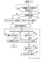
制御部10は充電検出部70の検出結果に基づいて表示装置20(表示領域2a)の表示を制御する。図8は制御部10の動作の一例を示すフローチャートである。この動作は電子機器1が起動した状態(直流電源が各部に供給されて起動した状態、通常モードとも呼ぶ)で実行される。
<
The
まずステップS1にて、制御部10は、充電器からの電力の伝送があるか否かを判定する。これは、充電検出部70からの検出結果を用いて判定される。例えば電圧検出部72,74の少なくともいずれか一方が基準値を超える電圧を検出しているときに、制御部10は充電器からの電力を受け取っていると判定する。ステップS1において否定的な判定がなされれば、再びステップS1を実行する。
First, in step S1, the
ステップS1において肯定的な判定がなされれば、ステップS2にて、制御部10は、非接触充電を行うか否かを判定する。これも充電検出部70の検出結果を用いて判定される。例えば電圧検出部72が基準値を超える電圧を検出しており、かつ、電圧検出部74が基準値を下回る電圧を検出しているときに、制御部10は非接触充電を行うと判定する。ステップS2において肯定的な判定がなされると、ステップS4にて制御部10は非接触充電を行っている旨を、表示領域2aのうち一部(例えばピクト表示領域2b)のみにおいて表示する。例えば図9に示すように、非接触充電を行なっている旨を示す図形22aおよび文字22bを表示する。図9の例示では、図形22aは黒丸に白抜きでPが表示された図形であり、文字22bは"Wireless Charging Enabled"である。
If a positive determination is made in step S1, in step S2, the
制御部10は一定時間経過後に図形22aの表示を維持しつつ、文字22bの表示を終了させても良い。一定時間の経過は周知のタイマー回路を用いることで計時できる。文字22bの表示を終了させることで、文字22bが表示されていた領域を他の通知に用いることができる。しかも、文字22bの表示面積は図形22aの表示面積よりも大きいので、図形22aの表示を終了させる場合に比べて、他の通知に利用できる領域を広く採ることができる。
The
ステップS4の次のステップS5にて、制御部10は、充電を行なっている旨を充電方法の区別無しに表示する。例えば図9に示すように、制御部10はLED表示部40を制御して発光素子を発光させるとともに、ピクト表示領域2bのバッテリー残量を示す図形22cを、充電を行なっていることを示す図形22dに変更する。
In step S5 following step S4, the
一方で、ステップS2にて否定的な判定がなされたときには、ステップS3にて制御部10は非接触充電を行っている旨の表示を行なうことなく、ステップS5を実行する。なおステップS3において制御部10は実質的な動作を行なう必要がないので、ステップS3は設けられなくても構わない。
On the other hand, when a negative determination is made in step S2,
ステップS5の動作はステップS2の判定結果によらず実行されるので、LED表示部40の発光および図形22dの表示は、充電用コネクタ84の電圧を用いた充電か、充電用コイル82aの誘導起電力を用いた充電か否かにかかわらず行なわれる。
Since the operation of step S5 is executed regardless of the determination result of step S2, the light emission of the
ステップS5の次に、ステップS6,S7の動作と、ステップS8〜S11の動作とを並行して行なう。これらの並行動作は例えば時分割で行なわれる。或いは、制御部10が2つの動作を同時期に実行することができれば、同時期に行なってもよい。
Following step S5, the operations of steps S6 and S7 and the operations of steps S8 to S11 are performed in parallel. These parallel operations are performed in a time division manner, for example. Alternatively, if the
ステップS6にて、制御部10は充電器からの電力の伝送がなくなったか否かを判定する。これは、充電検出部70の検出結果を用いて判定される。例えば電圧検出部72,74のいずれもが基準値を下回る電圧を検出しているときに、充電器からの電力の伝送がなくなったと判定する。ステップS6にて否定的な判断がなされると、未だ充電が行なわれていると判定して、再びステップS6を実行する。ステップS6にて肯定的な判断がなされると、充電が終了したと判定してステップS7を実行する。ステップS7においては、制御部10はLED表示部40の発光を停止させ、ピクト表示領域2bにおいて図形22a(必要であれば文字22b)の表示を終了し、図形22dを図形22cに切り替える。そして処理を終了する。つまり充電が終了すれば、充電用の表示も終了させるのである。
In step S6, the
次にステップS8〜S11の動作について説明する。なお、ステップS8〜S11の動作は非接触充電が行われることを前提とした動作であるので、非接触充電が行われているときのみ実行してもよい。 Next, operations in steps S8 to S11 will be described. In addition, since operation | movement of step S8-S11 is operation | movement on the assumption that non-contact charge is performed, you may perform only when non-contact charge is performed.
ステップS8においては、制御部10は、ステップS9の実行のトリガとなる操作があったか否かを判定する。この操作の有無は例えば操作キー50,52またはタッチパネル30への操作への操作の有無によって判定される。なお、後に述べる他の操作についても導お湯であるので繰り返しの説明を避ける。
In step S8, the
ここでは、次に説明する複数回の操作があったときにステップS9の実行のトリガとなる操作があったと判定する。例えば制御部10は第1の操作を受けて表示領域2aに通知画面(Notification Window)を表示する。通知画面とは、ピクト表示領域2bに表示された通知内容を表示するための画面である。第1の操作としては、例えば操作子を上側の領域外から表示領域2aの内側へとスライドさせる操作を採用できる。この第1の操作はタッチパネル30で検出される。
Here, it is determined that there is an operation that triggers execution of step S9 when there are a plurality of operations described below. For example, in response to the first operation, the
図10は通知画面の一例を模式的に示す図である。この通知画面では、使用者に対する種々の通知が示される。例えば図10では、無線LANに接続する機能がオンになっているか否かを示す図形および文字を含む枠24aと、GPS機能がオンになっている否を示す図形および文字を含む枠24bとが表示されている。枠24a,24bの下方には、非接触充電を行なっていることを示す枠24cも表示される。そして使用者による枠24cに対する第2操作をタッチパネル30で検出すると、ステップS8において肯定的な判定がなされる。第2操作としては、操作子を表示領域2aの一部に近接させ、その後、操作子を表示領域2aから離す操作(いわゆるタップ)を採用できる。
FIG. 10 is a diagram schematically illustrating an example of a notification screen. On this notification screen, various notifications to the user are shown. For example, in FIG. 10, a
なお必ずしも複数回の操作を行なう必要はなく、任意の1回の操作を採用できる。例えば図9の図形22aあるいは文字22bに対する操作(例えばタップ)を検出したときに、ステップS8において肯定的な判定を行ってもよい。
It is not always necessary to perform a plurality of operations, and any one operation can be adopted. For example, when an operation (for example, a tap) on the graphic 22a or the
ステップS8にて否定的な判定がなされると再びステップS8を実行する。ステップS8にて肯定的な判定がなされると、ステップS9にて、制御部10は、充電用コイル82aの中心位置を示すための画面(以下、充電画面と呼ぶ)の表示を行なう。充電画面は例えば表示領域2aの全体(あるいは主領域の全体)に表示される。なおステップS9の直前において、例えばアプリケーションプログラムによって表示領域2aに表示画面が表示されている場合には、そのアプリケーションを適宜に中断した上で、表示領域2aに充電画面を表示するとよい。
If a negative determination is made in step S8, step S8 is executed again. If an affirmative determination is made in step S8, in step S9, the
図11は充電画面の一例を模式的に示している。充電画面では充電用コイル82aの中心を示す情報(図11では図形26a)が表示される。本実施の形態では上述のように、平面視において、充電用コイル82aの中心P1が表示領域2aの輪郭内に位置している。つまり、表示領域2aには、平面視において充電用コイル82aの中心P1と一致する位置が存在する。よって制御部10は、その位置において、中心P1を示す図形26aを表示する。図11では図形26aは図形22aと同じであるものの、これらを異ならせても構わない。この表示により、使用者は充電用コイル82aの中心位置を認識することができる。よって使用者は充電用コイル82aの中心P1と充電器側コイル8aの中心P2とを合わせるべく、電子機器1の位置を調整しやすい。
FIG. 11 schematically shows an example of the charging screen. On the charging screen, information indicating the center of the charging
また制御部10は充電画面において、充電用コイル82aの中心P1と充電器側コイル8aの中心P2とを一致させることを、使用者に促す情報(図11では文章26b)を表示しても良い。これにより、使用者は、充電用コイル82aの中心P1と充電器側コイル8aの中心P2との位置を一致させる必要性を明確に認識することができる。
Further, the
また制御部10は充電画面において、非接触充電が行なわれている旨を示す情報(図11では文字26c)を表示しても良い。文字26cは例えば文字22b(図9)と同じである。なお、文字22b,26cとして、例えば「非接触充電を実行中です。」あるいは「Wireless Charging」と表示しても良い。これにより、使用者は充電画面においても非接触充電が行なわれていることを明確に認識することができる。なお文字26cとともに、或いは文字26cに替えて、非接触充電が行なわれている旨を示す図形が表示されてもよい。
Further, the
図11の例示では、充電用コイル82aの中心P1と充電器側コイル8aの中心P2とを一致させることを、文章26bによって使用者に促した。しかるに文章26bに替えて、或いは文章26bとともに、図12に示すように、図形26eが表示されても良い。図形26eは、充電用コイル82aの中心P1と充電器側コイル8aの中心P2とを一致させることを、使用者に促すための図形である。
In the illustration of FIG. 11, the
図12の例示では、電子機器1を斜視図で模式的に示す平面261と、当該平面261の内部において図形26aを斜視図で示した図形262と、非接触充電器8を斜視図で模式的に示す平面263と、当該平面263の内部に斜視図で示された図形264とが、図形26eにおいて表示されている。図形262,264が斜視図では見づらいので、これらを平面視で見た図形265,266も表示されている。図12の例示では、図形262,265の対応を分かりやすくすべく、図形262側を始点とし、図形265側を終点とする矢印も示されている。図形264,266についても同様に矢印が示されている。この図形266は非接触充電器8において充電器側コイル8aの中心P2の位置を示すものであり、非接触充電器8の主面(より詳細には充電器側コイル8aの中心を示す位置)にも設けられていることが望ましい。これにより、図形266(264)が充電器側コイル8aの中心を示していることが、使用者に理解できる。また図形26eにおいて、斜視図の図形262,264の位置が互いに一致することを示す破線267も表示されている。
In the illustration of FIG. 12, a
このような図形26eにより、使用者は、電子機器1において図形26aが示された位置(つまり中心P1)と、非接触充電器8において図形266が示された位置(つまり中心P2)とを一致させる必要性を、直感的に理解できる。 With such a graphic 26e, the user matches the position where the graphic 26a is shown in the electronic device 1 (that is, the center P1) and the position where the graphic 266 is shown in the non-contact charger 8 (that is, the center P2). You can intuitively understand the need to make it happen.
なお図11の例示では、充電用コイル82aを模式的に示す複数の同心円が破線で図示されている。これらの同心円を充電画面においても表示して構わない。これにより、図形26eが充電用コイル82aの中心を示すことが直感的に理解できる。
In the illustration of FIG. 11, a plurality of concentric circles schematically showing the charging
また、充電用コイル82aの中心P1を示す図形26aに替えて、中心P1を示す文字が示されても良い。要するに、充電用コイル82aの中心P1を示す印が表示されればよい。
Further, instead of the figure 26a indicating the center P1 of the charging
ステップS9の次のステップS10にて、充電画面の表示を終了するトリガとなる第3操作が行なわれたか否かを判定する。例えば充電画面にはCloseボタン26dが表示されている。第3操作としては、例えばこのCloseボタン26dへの操作(例えばタップ)を採用することができる。ステップS10にて否定的な判定がなされると、再びステップS10を実行する。ステップS10にて肯定的な判定がなされると、ステップS11にて制御部10は充電画面の表示を終了し、表示領域2aをステップS9よりも前の表示画面に戻す。そして、再びステップS8を実行する。
In step S10 following step S9, it is determined whether or not a third operation serving as a trigger for ending the display of the charging screen has been performed. For example, a
以上のように本実施の形態では、非接触充電が行われた状態において、使用者による操作があったときに、充電用コイル82aの中心を示す図形26a(或いは文字)が配置された充電画面を表示する。つまり、非接触充電を行ったとしても、使用者による操作がない場合には、充電画面を表示しない。よって、充電の直前までの表示画面が維持される。言い換えれば、充電の直前まで実行されていたアプリケーションプログラムが実行し続ける。
As described above, in the present embodiment, the charging screen in which the graphic 26a (or characters) indicating the center of the charging
よって、使用者があるアプリケーションプログラムを電子機器1に実行させているときに、電池60の充電量の不足を懸念して非接触充電を行っても、そのアプリケーションの実行を阻害しない。よって利便性を向上することができる。
Therefore, even when the user causes the
しかも上述のように、非接触充電を行っている状態で使用者が所定の操作を行なえば、その操作に応じて充電用コイル82aの中心位置が表示される。これにより、使用者は充電用コイル82aの中心P1の位置を認識できる。よってこの中心P1を充電器側コイル8aの中心P2に合わせやすい。
In addition, as described above, if the user performs a predetermined operation while performing non-contact charging, the center position of the charging
なお上述の例では、ステップS6,S7の動作と、ステップS8〜S11の動作とは、並行して行なわれる。よって、ステップS9の充電画面の表示中に充電器からの電力の伝送が途絶えると、ステップS6にて肯定的な判定がなされるので、ステップS7にて充電画面の表示が終了する。これにより、表示領域2aを速やかに元の表示に戻すことができる。
In the above example, the operations in steps S6 and S7 and the operations in steps S8 to S11 are performed in parallel. Therefore, if the transmission of power from the charger is interrupted during the display of the charging screen in step S9, a positive determination is made in step S6, and thus the display of the charging screen is terminated in step S7. Thereby, the
また、非接触充電を行っていないときにも、ステップS8〜S11の動作を実行してもよい。このとき、非接触充電を行っていなくても、使用者による所定の操作によって、充電用コイル82aの中心が表示される。したがって、使用者は、非接触充電を行う前から充電用コイル82aの中心の位置を認識できる。よって、使用者は、充電用コイル82aおよび充電器側コイル8aの中心位置を合わせながら、電子機器1を非接触充電器8に載置しやすい。例えば充電用コネクタ84を用いた充電から非接触充電へと切り替えるときにも、予め充電用コイル82aの中心の位置を認識できるので、これらの中心位置を合わせながら電子機器1を載置しやすい。
Moreover, you may perform operation | movement of step S8-S11 also when not performing non-contact charge. At this time, even if non-contact charging is not performed, the center of the charging
<非接触充電と充電用コネクタを用いた充電>
非接触充電器8および接触充電器9の両方から電力の伝送があるときには、制御部10は例えば接触充電器9を優先して用いる。より具体的には、制御部10は選択部86を制御して充電用コネクタ84の電圧を電圧調整部88へと入力する。
<Non-contact charging and charging using a charging connector>
When power is transmitted from both the
上述の動作に鑑みると、制御部10は、ステップS9の充電画面を表示した状態で、接触充電器9からの電力の伝送がある、つまり充電用コネクタ84に電圧の入力があると判定したときには、その充電画面の表示を終了し、表示領域2aを元の表示画面に戻してもよい。これにより、実際の充電に応じた表示を速やかに行なうことができる。
In view of the above-described operation, when the
より具体的な動作としては、例えば非接触充電中に行なわれるステップS8〜S10の動作と並行して、制御部10は、接触充電器9からの電力の伝送があるか否かを判定する。これは、充電検出部70の検出結果に基づいて判定される。接触充電器9からの電力の伝送があると判定すると、制御部10はステップS8〜S10の動作を中止する。例えばステップS8の実行段階においては、制御部10は以後のステップS8の動作を行なわない。また例えばステップS9,S10を実行していれば、制御部10は、充電画面の表示を終了して表示領域2aを元の表示画面に戻し、その後、ステップS8〜S11の動作を行なわない。
As a more specific operation, for example, in parallel with the operations of steps S8 to S10 performed during non-contact charging, the
他方、再び接触充電器9が外されて非接触充電のみが行われる場合には、再びステップS8〜S11の動作も行えばよい。
On the other hand, when the
<伝送効率についての表示>
図13に例示する電子機器1は、図2の電子機器1に比して、伝送効率検出部90を更に備えている。伝送効率検出部90は、充電用コイル82aの中心P1と充電器側コイル8aの中心P2との間のズレ量に依存する伝送効率を検出する。例えば伝送効率が高いほど非接触充電部82の出力電圧は大きいので、伝送効率検出部90として電圧検出部72を採用することができる。この場合、伝送効率検出部90は充電検出部70の一部として実現される。検出された伝送効率(例えば出力電圧)は制御部10に入力される。
<Indication about transmission efficiency>
The
制御部10は充電画面において伝送効率を示す情報も表示する。この充電効率は数値または図形によって表示される。以下により具体的な動作について説明する。
The
まず、充電用コイル82aの中心P1と充電器側コイル8aの中心P2との位置が一致しているときの、伝送効率(ここでは出力電圧、以下、最大電圧と呼ぶ)を予め記憶しておく。例えば記憶部103に最大電圧を予め記憶する。
First, the transmission efficiency (herein, the output voltage, hereinafter referred to as the maximum voltage) when the center P1 of the charging
そして、ステップS9にて、制御部10は、電圧検出部72が検出した検出電圧を最大電圧で規格化した数値に基づいて、充電用画面において伝送効率も表示する。例えば規格化した数値をそのまま表示しても良い。これにより、使用者は伝送効率、即ち充電用コイル82aの中心P1と充電器側コイル8aの中心P2の間のズレ量を認識できる。あるいは、図14に例示するように、図形26fを表示してもよい。図形26fは当該数値を示す図形であり、例えば複数の長尺バーが積層されて構成されている。そして、制御部10は伝送効率が高いほど順に下から長尺バーの色を変更する。使用者は、色の変更された長尺バーの数によって、伝送効率を認識できる。色が変更された長尺バーの数が多いほど、伝送効率は高い。
In step S9, the
これによれば、使用者は充電画面の伝送効率(中心P1,P2のズレ量)を認識しながら電子機器1を調整することができ、中心P1,P2を合わせやすい。
According to this, the user can adjust the
上述の例では、伝送効率検出部90として電圧検出部72を例示した。しかるに、これに限らず、例えば伝送効率検出部90は誘導起電力(交流電圧)の振幅(大きさ)を検出してもよい。伝送効率が高いほど当該振幅が大きいからである。或いは、伝送効率が大きいほど、充電用コイル82aから出力される交流電流の振幅が大きいので、伝送効率検出部90として、当該交流電流または整流部82bの出力側を流れる電流を検出する電流検出部を用いても良い。或いは伝送効率が大きいほど、充電用コイル82aに鎖交する磁束が大きいので、伝送効率検出部90として、当該磁束を検出する磁気センサを用いてもよい。そして、中心P1,P2が一致するときの上記諸量(電流、磁束など)を規格値として予め記憶し、検出した諸量を規格値で規格化した数値に基づいて、伝送効率を表示すればよい。
In the above example, the
<スリープモード>
制御部10は、所定の時間を超えて操作を受けない場合に、電子機器1のモードを通常モードからスリープモードへと移行させる。通常モードとは、例えば表示装置20が表示画面を表示している状態と把握することができる。スリープモードとは、通常モードよりも消費電力の小さいモードである。スリープモードにおいて、例えば制御部10は表示装置20の表示(点灯)を中断する。表示装置20が液晶ディスプレイであれば、バックライトを消灯する。これにより、表示領域2aには何も表示されなくなる一方で、バックライトによる消費電力を回避できる。またこの場合、表示領域2aに対する操作も無効となる。
<Sleep mode>
The
そして、スリープモードを解除する操作(例えば操作キー50への短期間の押下)を検出すると、制御部10は電子機器1のモードをスリープモードから通常モードへと移行する。これにより、表示領域2aの表示が復活すると共に、表示領域2aに対する操作が有効となる。
Then, when detecting an operation for canceling the sleep mode (for example, pressing the
このような電子機器1において、スリープモードが採用された状態で例えば操作キー50が押下されたとしても、制御部10は充電画面を表示しなくてもよい。つまりスリープモードにおいて、制御部10は充電画面の表示を禁止してもよい。これにより、消費電力の低減を優先することができる。
In such an
<変形例>
上述の例では、ステップS4(図8)においてピクト表示領域2bに、非接触充電器8を用いた充電が行われる旨を示す図形22aおよび文字22bを表示した。しかるに、ステップS4の実行時点で、所定のアプリケーションによって表示領域2aの全体に表示画面が表示されている場合には、ピクト表示領域2bが表示されないので、図形22aおよび文字22bも表示されなくてもよい。ただし、当該アプリケーションが中断または終了し、ピクト表示領域2bが表示される場合には、図形22aおよび文字22bも表示することが望ましい。ステップS5で説明した図形22dも同様である。
<Modification>
In the above-described example, the graphic 22a and the
第2の実施の形態.
電子機器1の操作キー50には、電子機器1の通常モード/停止モード(言い換えれば電源の投入/遮断)の切り替え機能が割り当てられる。例えば当該操作キー50が比較的長い期間にわたって押され続けたことを制御部10が認識すると、電子機器1の通常モード/停止モードを切り替える。通常モードでは、制御部10は電池60からの直流電源を各部へと供給して各部を起動し、停止モードでは、各部(例えば無線通信部110、前面側撮像部160、裏面側撮像部170、表示装置20およびタッチパネル30など)への直流電源の供給を遮断して各部を停止させる。なお停止モードにおいても、いくつかの構成部には直流電源が供給される。例えば停止モードであっても制御部10には直流電源が供給され、制御部10は操作キー50への操作を認識することができる。その他、必要な構成部への直流電源が供給される。また表示装置20に着目すると、停止モードは、表示装置20へと直流電圧が供給されていない状態、あるいは、表示画面を示す画像信号を表示装置20へと出力していない状態と把握することができる。
Second embodiment.
The
なお通常モードを消費電力が大きい状態であると把握すれば、停止モードは通常モードよりも消費電力が小さい状態であると把握することができる。また停止モードは上述のスリープモードよりも更に消費電力が小さい状態である。例えば停止モードで起動する構成部の数はスリープモードで起動する構成部の数よりも少ない。 If it is understood that the normal mode is a state in which the power consumption is large, it can be understood that the stop mode is a state in which the power consumption is smaller than that in the normal mode. The stop mode is a state in which the power consumption is smaller than that of the sleep mode described above. For example, the number of components that are activated in the stop mode is smaller than the number of components that are activated in the sleep mode.
第1の実施の形態では、通常モードおよびスリープモードにおいて充電が行われたときの表示について述べた。第2の実施の形態では、停止モードにおいて充電が行われたときの表示について述べる。 In the first embodiment, the display when charging is performed in the normal mode and the sleep mode has been described. In the second embodiment, a display when charging is performed in the stop mode will be described.
第2の実施の形態では、停止モードにおいても充電検出部70は機能する。よって充電検出部70の機能を発揮するために直流電源が必要であれば、停止モードにおいても、充電検出部70には直流電源が供給される。
In the second embodiment, the
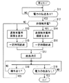
図15は、制御部10の動作の一例を示すフローチャートである。ステップS11,S12はステップS1,S2と同じである。ステップS12にて非接触充電器8を用いた充電が行われていると判定したときには、ステップS14において制御部10は非接触充電画面を表示する。なお、停止モードにおいて表示装置20が起動していない場合には、制御部10はまず表示装置20へと直流電源を供給して起動した上で、表示装置20に非接触充電用画面を表示させる。非接触充電画面には、平面視で充電用コイル82aの中心P1と一致する位置において、中心P1を示すための情報が含まれる。この非接触充電用画面としては、第1の実施の形態で述べた充電画面(図11、図12または図14)を採用することができる。第1の実施の形態で説明した各種情報(図形または文字等)を、非接触充電用画面に含ませることができる。これらが奏する効果も第1の実施の形態で述べたとおりである。
FIG. 15 is a flowchart illustrating an example of the operation of the
第2の実施の形態でも中心P1の位置が表示されるので、使用者は充電用コイル82aの中心P1を充電器側コイル8aの中心に一致させやすい。
Since the position of the center P1 is also displayed in the second embodiment, the user can easily align the center P1 of the charging
なおステップS14において、制御部10はLED表示部40を制御してその発光素子を発光させてもよい。
In step S14, the
次にステップS16において、制御部10がステップS14の実行から一定時間の経過を検出すると、ステップS17において、表示装置20を消灯する。一定時間の経過は周知のタイマー回路を用いて検出できる。表示装置20の消灯は、例えば表示装置20が液晶ディスプレイであれば、バックライトを消灯することで行なわれる。
Next, when the
ステップS12にて否定的な判定がなされたときには、ステップS13にて制御部10は通常充電用画面を表示する。なお、停止モードにおいて表示装置20が起動していない場合には、制御部10はまず表示装置20へと直流電源を供給して起動した上で、表示装置20に通常充電用画面を表示させる。通常充電用画面には、非接触充電か否かに拘わらず単に充電が行われている旨を示す表示が含まれる。図16は通常充電用画面の一例を模式的に示す図である。図16の例示では、表示領域2aの略中央に図形28aが示される。図形28aは例えば図形22c或いは図形22dと同様の図形である。
When a negative determination is made in step S12, the
図形28a以外の領域の画素には表示用電圧を印加しなくてもよい。この場合、当該他の領域では黒色が表示される。 The display voltage need not be applied to the pixels in the region other than the graphic 28a. In this case, black is displayed in the other area.
このような通常充電用画面の表示により、使用者は充電が適切に行われていることを明確に認識できる。 By displaying the normal charging screen, the user can clearly recognize that the charging is appropriately performed.
またステップS13において、制御部10はLED表示部40を制御してその発光素子を発光させてもよい。
In step S13, the
次にステップS15において、制御部10がステップS13の実行から一定時間の経過を検出すると、ステップS17において、制御部10は表示装置20を消灯する。
Next, in step S15, when the
このように、通常充電用画面または非接触充電用画面の表示は一定時間経過により消される。これにより、以後の消費電力を低減することができる。 In this way, the display of the normal charging screen or the non-contact charging screen is turned off after a certain period of time. Thereby, subsequent power consumption can be reduced.
ステップS17の次に、ステップS18,S19の判定を並行して行なう。ステップS18において、制御部10は充電確認の操作があったか否かを判定する。充電確認の操作としては、例えば操作キー50への比較的短時間の押下を採用することができる。充電確認の操作がないと判定されると、再びステップS18を実行し、充電確認の操作があったと判定されると、ステップS13を実行する。つまり充電確認の操作があったときには、非接触充電が行われているか否かに拘わらず、通常充電用画面を表示するのである。
Following step S17, the determinations of steps S18 and S19 are performed in parallel. In step S18, the
停止モードでは電子機器1が使用者によって使用されていないと想定されるので、電子機器1の位置が変わりにくいと想定される。よって、最初の1回目の表示では、非接触充電用画面を表示することで電子機器1の位置を適切な位置(充電用コイル82aの中心P1と充電器側コイル8aの中心P2とが一致する位置)へと移動させることを促し、以降の表示では通常充電用画面を表示しているのである。これにより、以降の表示においては、ステップS12に相当する判定処理を省略することができ、通常充電用画面を簡易に表示することができる。
Since it is assumed that the
上述の例では、充電用表示を最初の1回のみ表示しているが、例えば複数回の充電確認の操作に応じて非接触充電用画面を表示し、その後の充電確認の操作に応じて通常充電用画面を表示しても良い。より具体的には、制御部10は、充電確認の操作をカウントし、その操作数が例えば所定の回数よりも少ない場合に非接触充電用画面を表示し、その操作数が例えば当該回数以上であるときに通常充電用画面を表示すればよい。
In the above example, the charging display is displayed only once for the first time. For example, a non-contact charging screen is displayed in response to a plurality of charging confirmation operations, and a normal charging operation is performed in accordance with subsequent charging confirmation operations. A charging screen may be displayed. More specifically, the
また、図15のフローチャートによれば、ステップS14の非接触充電用画面を表示している最中において、充電確認の操作のあった場合には、ステップS13の通電充電用画面は表示されない。つまり、制御部10は、非接触充電用画面の表示を行っているときには、充電確認の操作を無効にする。これにより、適切に非接触充電用画面の表示を維持することができる。
Further, according to the flowchart of FIG. 15, when the operation for confirming charging is performed while the non-contact charging screen in step S <b> 14 is displayed, the energization charging screen in step S <b> 13 is not displayed. That is, the
またステップS13の通常充電用表示画面の表示中、或いはステップS14の非接触充電用画面の表示中に、充電器からの電力の伝送が途絶えると、制御部10はこれらの表示を終了して、表示装置20を消灯してもよい。より具体的には、制御部10は、ステップS13,S15,S14,S16の動作と並行して、ステップS19に相当する動作を実行し、充電器からの電力が途絶えたときに、ステップS13,S15,S14,S16の動作を中止してステップS17と同じ動作を実行すればよい。そして再びステップS11の動作を実行する。
Further, when the transmission of power from the charger is interrupted during the display of the normal charging display screen in step S13 or the non-contact charging screen in step S14, the
また非接触充電器8および接触充電器9の両方からの電力の伝送があったときに、接触充電器9を用いて充電を行う場合には、次のように表示を制御してもよい。すなわち、ステップS14の非接触充電用画面の表示中に、接触充電器9からの電力の伝送があったときには、制御部10は非接触充電用画面の表示を終了する。より具体的には、制御部10はステップS14,S16の動作と並行して、制御部10は接触充電器9からの電力の伝送があったか否かを判定する。そして肯定的な判定がなされれば、ステップS14,S16を中止し、一定時間の経過を待たずに非接触用充電画面の表示を終了する。例えばステップS17の動作を実行する。その後は、ステップS18,S19の動作を並行して行なう。
When power is transmitted from both the
このような動作により、速やかに非接触充電用画面の表示を終了させることができる。また以後も、充電確認の操作に応じて通常表示用画面を表示できる。 By such an operation, the display of the non-contact charging screen can be promptly terminated. Thereafter, the normal display screen can be displayed in accordance with the charging confirmation operation.
なおスリープモードにおいては、第1の実施の形態で述べたように、充電確認の操作(操作キー50の操作)があったとしても、制御部10は充電画面(通常充電用画面も含む)の表示を行なわない。これにより、消費電力の低減を優先することができる。
In the sleep mode, as described in the first embodiment, even if there is an operation for confirming charging (operation of the operation key 50), the
また上記の例では、本願発明を携帯電話機に適用する場合を例にあげて説明したが、本願発明は、スマートフォン等の携帯電話機以外の電子機器、例えばタブレット端末等にも適用することができる。 In the above example, the case where the present invention is applied to a mobile phone has been described as an example. However, the present invention can also be applied to an electronic device other than a mobile phone such as a smartphone, such as a tablet terminal.
以上のように、電子機器1は詳細に説明されたが、上記した説明は、全ての局面において例示であって、この発明がそれに限定されるものではない。また、上述した各種実施の形態および変形例は、相互に矛盾しない限り組み合わせて適用可能である。そして、例示されていない無数の変形例が、この発明の範囲から外れることなく想定され得るものと解される。
As mentioned above, although the
1 電子機器
2a 表示領域
10 制御部
20 表示装置
30 タッチパネル
50 操作キー
8a 充電器側コイル
82a 充電用コイル
84 充電用コネクタ
86 選択部
DESCRIPTION OF
Claims (9)
外部の充電器側コイルからの磁界が鎖交することで誘導起電力を発生させる充電用コイルと、
前記誘導起電力によって充電される電池と、
表示領域を有し、平面視において、前記表示領域の輪郭内に前記充電用コイルの中心と一致する位置が存在する表示装置と、
操作部と、
前記表示装置に表示を行う第1モードを有する制御部と
を備え、
前記制御部は、
前記第1モードにおいて、前記誘導起電力を用いた前記電池の充電が行われている間、前記充電に関する通知情報を前記表示領域に表示して消去せず、当該通知情報に対する操作を前記操作部が受けたとき、前記充電用コイルの中心を示す情報を前記表示領域に表示する、
電子機器。 Electronic equipment,
A charging coil that generates an induced electromotive force by interlinking magnetic fields from an external charger side coil; and
A battery charged by the induced electromotive force;
A display device having a display area and having a position that coincides with the center of the charging coil in the outline of the display area in a plan view;
An operation unit;
A control unit having a first mode for displaying on the display device,
The controller is
In the first mode, while the battery is charged using the induced electromotive force, the notification information related to the charging is not displayed in the display area and is not erased, and an operation on the notification information is performed on the operation unit. Is received, information indicating the center of the charging coil is displayed in the display area,
Electronics.
前記制御部の制御を受けて、前記充電用コネクタからの前記電圧と前記誘導起電力との一方を選択し、前記一方を用いて前記電池を充電する選択部と
を備え、
前記制御部は、前記充電用コネクタに前記電圧が入力され、かつ、前記誘導起電力が発生しているときに、前記選択部に前記充電用コネクタからの前記電圧を選択させ、
前記制御部は、前記表示領域に前記充電用コイルの中心を示す情報が表示された状態で、前記充電用コネクタに前記電圧が入力されたときに、前記充電用コイルの中心を示す情報の表示を終了する、請求項1から5のいずれか一つに記載の電子機器。 A connector for charging that is detachably and electrically connected to an external contact charger and to which a voltage is input from the contact charger;
Under the control of the control unit, select one of the voltage and the induced electromotive force from the charging connector, and comprises a selection unit that charges the battery using the one,
The control unit causes the selection unit to select the voltage from the charging connector when the voltage is input to the charging connector and the induced electromotive force is generated.
Wherein, in a state where the information indicating the center of the charging coil in the display region is displayed, when the voltage to the charging connector is input, it displays the information indicating the center of the charging coil The electronic device according to claim 1, wherein the electronic device is terminated.
前記第2モードにおいて、前記充電が行われたとき、前記表示装置を起動し、前記充電用コイルの中心を示す情報を前記表示領域に表示する、
請求項1から6のいずれか一つに記載の電子機器。 The control unit further includes a second mode in which power consumption is smaller than that in the first mode and no display is performed on the display device,
In the second mode, when the charging is performed, the display device is activated, and information indicating the center of the charging coil is displayed in the display area.
The electronic device as described in any one of Claim 1 to 6.
前記誘導起電力によって充電される電池と、
表示領域を有し、平面視において、前記表示領域の輪郭内に前記充電用コイルの中心と一致する位置が存在する表示装置と、
操作部と
を備える電子機器における表示方法であって、
前記表示装置に表示を行う第1モードにおいて、前記誘導起電力を用いた前記電池の充電が行われている間、前記充電に関する通知情報を前記表示領域に表示して消去せず、当該通知情報に対する操作を受けたとき、前記充電用コイルの中心を示す情報を前記表示領域に表示する、
電子機器における表示方法。 A charging coil that generates an induced electromotive force by interlinking magnetic fields from an external charger side coil; and
A battery charged by the induced electromotive force;
A display device having a display area and having a position that coincides with the center of the charging coil in the outline of the display area in plan view;
A display method in an electronic device including an operation unit,
In a first mode for performing display on the display device, while the charging of the battery using the induced electromotive force is taking place, without deleting displays the notification information on the charge in the display area, the notification information When receiving the operation for, information indicating the center of the charging coil is displayed in the display area,
Display method in electronic equipment.
Priority Applications (3)
| Application Number | Priority Date | Filing Date | Title |
|---|---|---|---|
| JP2014064355A JP6219210B2 (en) | 2014-03-26 | 2014-03-26 | Electronic device and display method in electronic device |
| PCT/JP2015/059328 WO2015147144A1 (en) | 2014-03-26 | 2015-03-26 | Electronic device and display method in electronic device |
| US15/272,195 US9819217B2 (en) | 2014-03-26 | 2016-09-21 | Electronic device, display method in electronic device, and non-transitory computer readable recording medium |
Applications Claiming Priority (1)
| Application Number | Priority Date | Filing Date | Title |
|---|---|---|---|
| JP2014064355A JP6219210B2 (en) | 2014-03-26 | 2014-03-26 | Electronic device and display method in electronic device |
Publications (2)
| Publication Number | Publication Date |
|---|---|
| JP2015188274A JP2015188274A (en) | 2015-10-29 |
| JP6219210B2 true JP6219210B2 (en) | 2017-10-25 |
Family
ID=54195651
Family Applications (1)
| Application Number | Title | Priority Date | Filing Date |
|---|---|---|---|
| JP2014064355A Active JP6219210B2 (en) | 2014-03-26 | 2014-03-26 | Electronic device and display method in electronic device |
Country Status (3)
| Country | Link |
|---|---|
| US (1) | US9819217B2 (en) |
| JP (1) | JP6219210B2 (en) |
| WO (1) | WO2015147144A1 (en) |
Families Citing this family (10)
| Publication number | Priority date | Publication date | Assignee | Title |
|---|---|---|---|---|
| JP6505372B2 (en) * | 2014-03-26 | 2019-04-24 | 京セラ株式会社 | Electronic device and control method of electronic device |
| JP6677520B2 (en) * | 2016-02-09 | 2020-04-08 | キヤノン株式会社 | Information processing apparatus, control method, and program |
| CN107317374B (en) * | 2017-07-28 | 2020-06-19 | 维沃移动通信有限公司 | Charging area display method and wireless charger |
| CN108448666A (en) * | 2018-03-16 | 2018-08-24 | 联想(北京)有限公司 | A kind of information processing method and electronic equipment |
| CN109617252B (en) * | 2019-01-02 | 2023-01-24 | 京东方科技集团股份有限公司 | Wireless charging device, equipment, system and method |
| CN110649719A (en) * | 2019-08-23 | 2020-01-03 | 华为技术有限公司 | Wireless charging method and electronic equipment |
| CN112994259A (en) * | 2019-12-18 | 2021-06-18 | 深圳市万普拉斯科技有限公司 | Wireless charging method and device, computer equipment and readable storage medium |
| CN110994731B (en) * | 2019-12-20 | 2022-01-07 | Oppo广东移动通信有限公司 | Charging prompting method and device, electronic equipment and computer readable storage medium |
| WO2022185728A1 (en) * | 2021-03-04 | 2022-09-09 | ソニーグループ株式会社 | Information processing device, information processing method, and program |
| US12061830B1 (en) | 2021-10-13 | 2024-08-13 | Glass-Media, Inc. | Interactive display apparatus and method of use |
Family Cites Families (12)
| Publication number | Priority date | Publication date | Assignee | Title |
|---|---|---|---|---|
| JP2003134699A (en) * | 2001-10-26 | 2003-05-09 | Olympus Optical Co Ltd | Electronic camera and battery charger |
| JP3996171B2 (en) | 2005-04-28 | 2007-10-24 | パナソニック モバイルコミュニケーションズ株式会社 | Battery pack lid providing non-contact charging interface and mobile phone including the battery pack lid |
| WO2009097555A2 (en) * | 2008-01-30 | 2009-08-06 | Google Inc. | Notification of mobile device events |
| EP2199142B1 (en) * | 2008-12-22 | 2013-04-17 | Aisin Aw Co., Ltd. | Guidance device for charging vehicle battery |
| JP5348183B2 (en) * | 2010-08-18 | 2013-11-20 | 三洋電機株式会社 | Battery built-in equipment and charger |
| KR20120020661A (en) * | 2010-08-30 | 2012-03-08 | 엘지전자 주식회사 | Mobile terminal and method for wireless charging |
| KR101832492B1 (en) * | 2011-06-10 | 2018-02-26 | 삼성전자주식회사 | Device and method for confirming remaining amount of battery in wireless terminal |
| US9171139B2 (en) * | 2011-08-05 | 2015-10-27 | Vmware, Inc. | Lock screens to access work environments on a personal mobile device |
| WO2013136394A1 (en) * | 2012-03-16 | 2013-09-19 | Necカシオモバイルコミュニケーションズ株式会社 | Information processing device, notification control method and program |
| JP2013215036A (en) * | 2012-04-02 | 2013-10-17 | Sharp Corp | Charging guidance system, electronic apparatus, charging guidance program, and recording medium |
| JP2014027738A (en) * | 2012-07-25 | 2014-02-06 | Nec Casio Mobile Communications Ltd | Portable device, control method thereof, and program |
| US20140306646A1 (en) * | 2013-03-16 | 2014-10-16 | Wei-Ting Liu | Wireless Charger |
-
2014
- 2014-03-26 JP JP2014064355A patent/JP6219210B2/en active Active
-
2015
- 2015-03-26 WO PCT/JP2015/059328 patent/WO2015147144A1/en active Application Filing
-
2016
- 2016-09-21 US US15/272,195 patent/US9819217B2/en active Active
Also Published As
| Publication number | Publication date |
|---|---|
| JP2015188274A (en) | 2015-10-29 |
| US20170012460A1 (en) | 2017-01-12 |
| WO2015147144A1 (en) | 2015-10-01 |
| US9819217B2 (en) | 2017-11-14 |
Similar Documents
| Publication | Publication Date | Title |
|---|---|---|
| JP6219210B2 (en) | Electronic device and display method in electronic device | |
| JP6505372B2 (en) | Electronic device and control method of electronic device | |
| US10649576B2 (en) | Electronic device with protective case and operating method thereof | |
| EP2701277B1 (en) | Method and apparatus for wireless charging an electronic device | |
| US8909300B2 (en) | Mobile terminal and controlling method of displaying direction | |
| US20130234659A1 (en) | Wireless charging system and method | |
| US20170026069A1 (en) | Mobile electronic apparatus, accessory device therefor, and electronic apparatus including the accessory device | |
| JP6163133B2 (en) | Electronic device and charging notification method in electronic device | |
| KR20130129745A (en) | Mobile terminal and control method thereof | |
| JP2008211951A (en) | Non contact type charger and non contact type charging apparatus | |
| EP3849049A1 (en) | Wireless charging method and device, foldable-screen electronic device and storage medium | |
| KR101988035B1 (en) | Mobile communication terminal and electric aharging mobile of wireless and control method thereof | |
| US8620392B2 (en) | Electronic device capable of continuing a telephone call when charging | |
| US10601261B2 (en) | Portable electronic device, method, and computer-readable recording medium | |
| US9813546B2 (en) | Electronic apparatus and method for controlling electronic apparatus | |
| US10021303B2 (en) | Electronic apparatus, recording medium and electronic apparatus system | |
| JP6357278B2 (en) | Electronic device and charging method | |
| US7973513B2 (en) | Systems and methods for ubiquitous charging | |
| JP2019144724A (en) | Electronic apparatus and control method | |
| JP2017069612A (en) | Mobile electronic apparatus | |
| US11557925B2 (en) | Wireless charging positioning device and method, and storage medium | |
| KR20150080823A (en) | Method for data output based on an object recognition and an electronic device thereof | |
| KR20160058468A (en) | Mobile terminal |
Legal Events
| Date | Code | Title | Description |
|---|---|---|---|
| A621 | Written request for application examination |
Free format text: JAPANESE INTERMEDIATE CODE: A621 Effective date: 20160713 |
|
| A131 | Notification of reasons for refusal |
Free format text: JAPANESE INTERMEDIATE CODE: A131 Effective date: 20170328 |
|
| A521 | Request for written amendment filed |
Free format text: JAPANESE INTERMEDIATE CODE: A523 Effective date: 20170525 |
|
| A131 | Notification of reasons for refusal |
Free format text: JAPANESE INTERMEDIATE CODE: A131 Effective date: 20170613 |
|
| A521 | Request for written amendment filed |
Free format text: JAPANESE INTERMEDIATE CODE: A523 Effective date: 20170808 |
|
| TRDD | Decision of grant or rejection written | ||
| A01 | Written decision to grant a patent or to grant a registration (utility model) |
Free format text: JAPANESE INTERMEDIATE CODE: A01 Effective date: 20170905 |
|
| A61 | First payment of annual fees (during grant procedure) |
Free format text: JAPANESE INTERMEDIATE CODE: A61 Effective date: 20170927 |
|
| R150 | Certificate of patent or registration of utility model |
Ref document number: 6219210 Country of ref document: JP Free format text: JAPANESE INTERMEDIATE CODE: R150 |