JP6219085B2 - Power system stabilization system and power system stabilization method - Google Patents
Power system stabilization system and power system stabilization method Download PDFInfo
- Publication number
- JP6219085B2 JP6219085B2 JP2013155953A JP2013155953A JP6219085B2 JP 6219085 B2 JP6219085 B2 JP 6219085B2 JP 2013155953 A JP2013155953 A JP 2013155953A JP 2013155953 A JP2013155953 A JP 2013155953A JP 6219085 B2 JP6219085 B2 JP 6219085B2
- Authority
- JP
- Japan
- Prior art keywords
- control
- reclosing
- failure
- accident
- assuming
- Prior art date
- Legal status (The legal status is an assumption and is not a legal conclusion. Google has not performed a legal analysis and makes no representation as to the accuracy of the status listed.)
- Active
Links
Images


Landscapes
- Supply And Distribution Of Alternating Current (AREA)
- Remote Monitoring And Control Of Power-Distribution Networks (AREA)
Description
本発明の実施形態は、電力系統安定化システムおよび電力系統安定化方法に関する。 Embodiments described herein relate generally to a power system stabilization system and a power system stabilization method.
電力系統に落雷などの事故が発生した場合、事故除去リレーシステムによって高速かつ最小範囲での事故除去が行われ、系統への影響は最小限に抑えられる。しかし、事故除去リレーシステムの動作にもかかわらず、遮断器不動作などによる事故除去時間の遅延、広範囲な事故遮断、ルート断事故などの重大事故の発生などに起因して事故除去後の系統構成が大幅に変化したりする場合には、潮流急変、大幅な需給アンバランスなどを引き起こし、系統の異常現象が発生する場合がある。これを放置すると、発生した異常現象が電力系統全体へ波及して大停電に拡大する恐れがあるため、このような異常現象の発生を未然に防止したり、系統全体への波及拡大を防止したりする事故波及防止リレーシステムがある。 When an accident such as a lightning strike occurs in the power system, the accident elimination relay system removes the accident at a high speed and in the minimum range, and the influence on the system is minimized. However, despite the operation of the accident elimination relay system, the system configuration after the accident elimination due to the occurrence of a major accident such as a delay in accident elimination due to circuit breaker malfunction, wide-range accident interruption, route interruption accident, etc. In the case of a drastic change, an abnormal phenomenon of the system may occur due to a sudden change in the tidal current and a significant imbalance in supply and demand. If this is left unattended, an abnormal phenomenon that occurs may spread to the entire power system and spread to a major power outage.Therefore, the occurrence of such an abnormal phenomenon or the spread of the entire system can be prevented. There is a relay system to prevent accidents.
事故波及防止リレーシステムは、通称、電力系統安定化システムあるいは電力系統安定化装置と呼ばれ、対象とする電力系統における異常現象(脱調現象、周波数異常、電圧異常、過負荷)に応じて様々な種類がある。 Accident Ripple Prevention Relay System, commonly known as a power system stabilization system or power system stabilization device, varies depending on the abnormal phenomenon (step out phenomenon, frequency abnormality, voltage abnormality, overload) in the target power system. There are various types.
以下、説明を簡単化するため、電力系統安定化システムの例として発電機や系統間の脱調現象の発生を未然に防止する脱調未然防止リレーシステムを用いて説明する。他の異常現象(周波数異常、電圧異常、過負荷)を対象とする電力系統安定化システムについても同様のことが言える。 Hereinafter, in order to simplify the explanation, an out-of-step prevention relay system that prevents the occurrence of a step-out phenomenon between the generator and the system will be described as an example of the power system stabilization system. The same can be said for the power system stabilization system for other abnormal phenomena (frequency abnormality, voltage abnormality, overload).
電力系統安定化システムを制御内容の演算方式で分類すると、大きく分けて事前演算型と事後演算型の2つに分類される。 When the power system stabilization system is classified by the calculation method of the control content, it is roughly classified into two types, a pre-calculation type and a post-calculation type.
事後演算型は、事故中および事故後の系統情報からオンラインで将来の現象について予測計算を行い、その結果に基づき制御対象発電機などの制御量を演算し、即座に制御を実施する方式である。 The post-calculation type is a method that performs predictive calculations for future phenomena online from system information during and after the accident, calculates the controlled variable of the controlled generator based on the results, and immediately performs control. .
一方、事前演算型は、事故および系統現象を想定して、事故前の系統情報から制御量を予め演算、設定しておき、実際に事故が発生した場合、設定を参照し、即座に制御を実施する方式である。 On the other hand, the pre-computation type calculates and sets the control amount from the system information before the accident, assuming accidents and system phenomena, and if an accident actually occurs, refer to the settings and control immediately. This is the method to be implemented.
さらに事前演算型は、オフライン事前演算型とオンライン事前演算型に分類される。 Further, the pre-calculation type is classified into an offline pre-calculation type and an online pre-calculation type.
オフライン事前演算型はオフラインの安定度計算に基づいて制御テーブルを決定するのに対し、オンライン事前演算型はオンラインで入手した系統情報(オンラインデータ)を用いて安定度計算を実施して制御テーブルを作成する点が異なるが、想定する系統事故種別に対する制御内容を演算して決定し、その結果を制御テーブルとして記憶しておき、事故発生時に事故種別と制御テーブルを照合して制御内容を決定する点は共通である。 The offline pre-computation type determines the control table based on the offline stability calculation, while the online pre-computation type performs stability calculation using the system information (online data) obtained online. Although the points to be created are different, the control content for the assumed system fault type is calculated and determined, the result is stored as a control table, and the control type is determined by comparing the accident type with the control table when an accident occurs The point is common.
架空送電線においては事故の大部分が雷によるものであり、保護リレー動作により送電線の遮断器を開放して事故電流が遮断されれば絶縁が回復するので、遮断器を再投入し、運転を継続することができる。これらの操作を自動的に行うのが自動再閉路(以下、再閉路)であり、架空送電線に広く適用されている。 In overhead power transmission lines, most of the accidents are caused by lightning, and the insulation is restored if the circuit breaker of the power transmission line is opened and the accident current is interrupted by the protective relay operation. Can continue. Automatic reclosing (hereinafter referred to as reclosing) that automatically performs these operations is widely applied to overhead power transmission lines.
再閉路には遮断してから投入指令を出すまでの時間(無電圧時間)の長さの違いから、高速、中速、低速の再閉路があり、また遮断相の違いから、単相、三相、多相などの再閉路方式がある。 There are high-speed, medium-speed, and low-speed reclosing due to the difference in the length of time (no-voltage time) from when the closing is made to when the closing command is issued to the reclosing circuit. There are reclosing methods such as phase and multiphase.
再閉路は事故除去のために一旦切り離された送電線を再び併用する行為であり、事故発生前の状態に速やかに回復させることができるため、再閉路が成功すれば過渡安定度を向上できる効果がある。 Reclosing is the act of reusing a transmission line that was once disconnected to eliminate the accident, and since it can be quickly restored to the state before the accident occurred, the effect of improving transient stability if the reclosing is successful. There is.
つまり、再閉路が成功する場合と失敗する場合とでは電力系統の安定度が異なるため、安定化に必要な制御量も異なるが、従来の電力系統安定化システムでは、事前演算の処理負担増加や事故発生後の短時間に再閉路の成功/失敗を検出して制御を切替える処理が複雑である、制御を行うタイミングが遅くなると制御量が増加する、等の理由から、再閉路の成功または失敗のどちらかを想定して制御内容を設定し、事故発生を検出したら直ちに制御を行うようにしている。 In other words, the stability of the power system differs between when the reclosing is successful and when it fails, so the amount of control required for stabilization also differs.However, in the conventional power system stabilization system, the processing load of the pre-computation is increased. Success or failure of reclosing because the process of switching control by detecting success / failure of reclosing in a short time after the occurrence of an accident is complicated, or when the control timing is delayed, the control amount increases. The control content is set assuming either of these, and the control is performed immediately after the occurrence of an accident is detected.
制御量が不足すると電力系統の安定度が維持できないので、従来の事前演算型の電力系統安定化システムでは、一般に、再閉路失敗を想定して制御内容を決めている。このため、再閉路が成功した際には過剰制御になる可能性がある。 Since the stability of the power system cannot be maintained if the control amount is insufficient, the conventional pre-computation type power system stabilization system generally determines the control contents assuming a reclosing failure. For this reason, there is a possibility of overcontrol when the reclosing is successful.
過剰制御の問題として、過剰な電源制限に起因した周波数異常や供給障害の発生や、必要以上に制御した発電設備等を復旧操作する運用者の負担増加などがある。 Problems of excessive control include occurrence of frequency abnormalities and supply failures due to excessive power supply restrictions, and an increase in the burden on the operator who restores power generation facilities controlled more than necessary.
このように、従来の事前演算型の電力系統安定化システムは再閉路失敗を想定して制御内容を決めているため、再閉路が成功した際には過剰制御になる可能性がある。 As described above, since the conventional pre-computation type power system stabilization system determines the control content on the assumption of reclosing failure, there is a possibility of over-control when the reclosing succeeds.
そこで、発明が解決しようとする課題は、過剰制御を防止することができる事前演算型の電力系統安定化システムを提供することにある。 Therefore, the problem to be solved by the invention is to provide a pre-computation type power system stabilization system capable of preventing over-control.
実施形態によれば、電力系統安定化システムは、電力系統の安定度維持に必要な電制発電機を示す情報を制御テーブルに設定し該制御テーブルを送信する中央演算装置と、系統事故発生時に事故種別を判定し該事故種別の情報を送信する事故検出端末装置と、前記中央演算装置から送信される制御テーブルを受信するとともに前記事故検出端末装置から送信される事故種別の情報を受信し該事故種別を該制御テーブルと照合して電制発電機を決定する演算装置と、前記演算装置により決定された電制発電機を電力系統から解列させる制御端末装置と、を備えて成る事前演算型の電力系統安定化システムにおいて、前記中央演算装置は、系統事故が発生した際の電力系統の安定度維持に必要な制御内容として、想定される事故種別ごとに、再閉路成功を想定した制御内容と再閉路失敗を想定した制御内容とをそれぞれ求めて制御テーブルに設定し、前記事故検出端末装置は、系統事故発生時に判定した事故種別の情報を前記演算装置へ送信するとともに、事故発生のタイミングから無電圧時間経過後に送電線保護リレーの動作信号を受信した場合に再閉路失敗と判定し再閉路失敗が検出されたことを示す信号を前記演算装置へ送信し、前記演算装置は、初めに再閉路成功を想定した制御内容による制御を行い、再閉路失敗が検出された場合は再閉路失敗を想定した制御内容による制御を追加で行うことを決定する。 According to the embodiment, the power system stabilization system includes a central processing unit that sets information indicating a control generator necessary for maintaining the stability of the power system in the control table and transmits the control table, and when a system fault occurs. Accident detection terminal device that determines the accident type and transmits information on the accident type, and receives the control table transmitted from the central processing unit and the information on the accident type transmitted from the accident detection terminal device A pre-computation comprising: an arithmetic device that determines an electric power generator by comparing the accident type with the control table; and a control terminal device that disconnects the electric power generator determined by the arithmetic device from the electric power system. in type power system stabilization system, the central processing unit, a control content required stability maintain the power system when the system fault occurs, each accident is assumed type, recloser Successful assumed control content and reclosing fails and assumed control contents determined respectively set in the control table, the fault detection terminal apparatus transmits information of the accident type is determined when a system fault occurs to the arithmetic unit And, when the operation signal of the transmission line protection relay is received after the no-voltage time has elapsed from the timing of the occurrence of the accident, a signal indicating that the reclosing failure is detected and the reclosing failure is detected is transmitted to the arithmetic unit, The arithmetic unit first performs control based on the control content assuming re-closing success, and when re-closing failure is detected, determines to additionally perform control based on the control content assuming re-closing failure.
事前演算型の電力系統安定化システムにおいて過剰制御を防止する過剰制御を防止することができる。 In the pre-computation type power system stabilization system, it is possible to prevent over-control that prevents over-control.
以下、図面を参照して、実施の形態について説明する。 Hereinafter, embodiments will be described with reference to the drawings.
(第1の実施形態)
図1〜図7を参照して、第1の実施形態について説明する。なお、図1,図2は、後述する各実施形態においても適宜使用する。
(First embodiment)
The first embodiment will be described with reference to FIGS. 1 and 2 are also used as appropriate in each embodiment described later.
図1は、第1の実施形態に係る系統安定化システムの構成の一例を示す図である。 FIG. 1 is a diagram illustrating an example of a configuration of a system stabilization system according to the first embodiment.
図1に示される系統安定化システムは、オンライン事前演算型の系統安定化システムであり、電力系統の接続状態および電力の需給状態を系統情報として給電情報網N経由で収集する系統情報収集手段101と、系統情報収集手段101により収集された系統情報と予め記憶されている系統設備データとに基づいて、現在の潮流状態を表わす解析用系統モデルを作成する系統モデル作成手段102と、系統モデル作成手段102により作成された解析用系統モデルと、予め記憶されている複数の想定事故種別データとに基づいて、複数の解析条件を設定する解析条件設定手段103と、解析条件設定手段103により設定された各解析条件に従って安定度計算を行ない、各解析条件に対する電力系統の安定度を判定し、各想定事故が発生した際に電力系統の安定度維持に必要な電制発電機(電源制限する発電機)を示す制御テーブルを設定する安定度判定手段104と、電力系統に事故が発生したことを起動条件とし、当該事故の種別を判定し検出する事故種別検出手段106と、事故種別検出手段106により検出された事故種別を安定度判定手段104により設定された各想定事故種別に対する電制発電機を記録した制御テーブルと照合して、電制発電機を決定する電制発電機決定手段105と、電制発電機決定手段105により決定された電制発電機を電力系統から解列させる制御手段107と、を備えて成る。
The system stabilization system shown in FIG. 1 is an online pre-computation system stabilization system, and system information collection means 101 collects the connection state of the power system and the power supply and demand state as system information via the power supply information network N. A system
ここで、上記解析条件設定手段103は、系統モデル作成手段102により作成された解析用系統モデルを記憶する系統モデル記憶部103aと、想定する複数の事故種別データを記憶している想定事故種別記憶部103bと、系統モデル記憶部103aおよび想定事故種別記憶部103bにそれぞれ記憶されている解析用系統モデルおよび想定事故種別データを用いて、電制発電機の組み合わせを変えて複数の解析条件を設定する解析条件設定部103cとから成るものであることが望ましい。
Here, the analysis
また、上記安定度判定手段104は、解析条件設定手段103により設定された各解析条件を記憶する解析条件記憶部104aと、当該解析条件記憶部104aに記憶されている各解析条件に対して過渡安定度計算を行なう過渡安定度計算部104bと、当該過渡安定度計算部104bによる計算結果を用いて、各解析条件に対する安定度を判定し、各想定事故が発生した際に電力系統の安定度維持に必要な電制発電機を求める安定度判定部104cと、安定度判定部104cの判定結果を制御テーブルとして設定する制御テーブル設定部104dと、から成るものであることが望ましい。
The
また、上記電制発電機決定手段105は、安定度判定手段104により設定された制御テーブルを記憶する制御テーブル記憶部105aと、事故種別検出手段106により検出された事故種別と前記制御テーブルを照合して、電制発電機を決定する照合処理部105bと、から成るものであることが望ましい。
The control
ここで、事故種別とは事故の様相のことであり、事故条件と呼ばれることもある。例えば、2回線送電線において1回線の1相だけで事故検出した場合の事故種別は1相1線地絡事故(1φ1LG)、1回線の3相で事故検出した場合は3相3線地絡事故(3φ3LG)、などと判定する。すなわち、事故種別検出手段106は、系統事故の発生を検出するとともに、事故検出した相の数などを検出することにより、事故種別を判定することができる。 Here, the accident type refers to the aspect of the accident and is sometimes referred to as an accident condition. For example, in the case of an accident detected with only one phase of one line in a two-line transmission line, the accident type is a one-phase one-line ground fault (1φ1LG), and when an accident is detected with three phases of one line, a three-phase three-wire ground fault It is determined that there is an accident (3φ3LG). That is, the accident type detection means 106 can determine the accident type by detecting the occurrence of a system fault and detecting the number of phases in which an accident has been detected.
事故種別検出手段106において系統事故を検出する方法には、送電線保護リレー等の事故除去リレーシステムの動作や、遮断器の状態変化、あるいは電力系統の電気量の変化を捉える方法があり、これらを複数組み合わせることによって系統事故を確実に検出することができる。 The method of detecting a system fault in the accident type detection means 106 includes a method of capturing an operation of an accident elimination relay system such as a power line protection relay, a state change of a circuit breaker, or a change in the amount of electricity in the power system. It is possible to reliably detect a system fault by combining a plurality of.
前述の手段を備えて成るオンライン事前演算型の系統安定化システムは、中央演算装置9と演算装置10と事故検出端末装置11と制御端末装置12とで構成される。
The online pre-calculation type system stabilization system including the above-described means includes a central processing unit 9, a
図2は、図1に示される系統安定化システムを構成する各装置の設置の一例を示す図である。 FIG. 2 is a diagram showing an example of installation of each device constituting the system stabilization system shown in FIG.
前述の中央演算装置9、演算装置10、事故検出端末装置11、および制御端末装置12は、図2に示されるように信号線などの通信設備8により接続される。また、電力系統には、発電機1、母線2、変圧器あるいは送電線3、遮断器(CB)4、電流計測器(CT)5、電圧計測器(PT)6、事故除去リレーシステム7が存在する。
The central processing unit 9, the
事故検出端末装置11は変電所など、制御端末装置12は発電所などにそれぞれ設置される。演算装置10は他の装置との通信が可能な個所に設置される。事故検出端末装置11や制御端末装置12と同じ場所に設置されることもある。さらには、演算装置10に、事故検出端末装置11や制御端末装置12の機能を含めて構成することもある。中央演算装置9は給電指令所など給電情報網Nと接続可能な個所に設置される。
The accident
本実施形態においては、想定事故種別記憶部103bに記憶される想定事故種別データについて、系統事故時の再閉路が成功する場合と再閉路が失敗する場合の両方を想定し、制御テーブル設定部104dには、事故種別ごとに、系統事故時の再閉路が成功する場合と再閉路が失敗する場合の両方の制御内容を設定する。 In the present embodiment, regarding the assumed accident type data stored in the assumed accident type storage unit 103b, both the case where the reclosing at the time of the system failure succeeds and the case where the reclosing fails, the control table setting unit 104d For each accident type, the control contents for both the case where the reclosing at the time of the system failure succeeds and the case where the reclosing fails are set.
具体的には、安定度判定手段104は、系統事故が発生した際の電力系統の安定度維持に必要な制御内容として、想定される事故種別ごとに、再閉路成功を想定した制御内容と再閉路失敗を想定した制御内容の両方をそれぞれ求めて制御テーブルに設定する。この場合、制御内容として電源制限する電制発電機を決定して該発電機を示す情報を制御テーブルに設定する処理を行う。また、電制発電機決定手段105は、系統事故発生時に、検出される事故種別を前記制御テーブルと照合して、初めに再閉路成功を想定した制御内容による制御を行い、再閉路失敗が検出された場合は再閉路失敗を想定した制御内容による制御を追加で行うことを決定する。
Specifically, the
図3に制御テーブルの設定例を示す。 FIG. 3 shows an example of setting the control table.
再閉路成功を想定した制御内容を第1段制御、再閉路失敗を想定した制御内容を第2段制御として設定する。但し、第1段制御は、系統事故発生時、再閉路の成功/失敗に関わらず最初に実施する制御である。 The control content assuming the reclosing success is set as the first stage control, and the control content assuming the reclosing failure is set as the second stage control. However, the first stage control is the control that is first performed when a system fault occurs regardless of the success / failure of the reclosing.
例えば、事故種別1の系統事故発生後の再閉路成功を想定した制御内容が発電機G1の電源制限で、再閉路失敗を想定した制御内容が発電機G2,G3の電源制限である場合、第1段制御の制御内容としてG1電源制限、第2段制御の制御内容としてG2,G3電源制限を設定する。 For example, when the control content assuming the reclosing success after the occurrence of a system fault of the accident type 1 is the power limitation of the generator G1, and the control content assuming the reclosing failure is the power limitation of the generators G2 and G3, The G1 power supply restriction is set as the control content of the first stage control, and the G2 and G3 power supply restrictions are set as the control content of the second stage control.
また、本実施形態においては、事故種別検出手段106は、事故種別判定と再閉路失敗検出を行う。図4に事故種別検出手段106の機能構成の例を、図5に再閉路失敗の検出ロジックの例を、図6に事故発生と制御実施のタイムチャートの例を示す。 In the present embodiment, the accident type detection means 106 performs accident type determination and reclosing failure detection. FIG. 4 shows an example of the functional configuration of the accident type detection means 106, FIG. 5 shows an example of a reclosing failure detection logic, and FIG. 6 shows an example of a time chart of accident occurrence and control execution.
図4に示されるように、事故種別検出手段106は、系統事故が発生した場合に事故検出部106aにより系統事故を検出し、事故種別判定部106bにより事故種別を判定し、送信部106dにより事故種別を送信する。また、事故種別検出手段106は、再閉路失敗が発生した場合には再閉路失敗検出部106cにより再閉路失敗を検出し、再閉路失敗検出を送信する。再閉路失敗検出部106cは、図5に示されるように、事故検出部106aにより検出される事故発生のタイミングから無電圧時間(79TB1)経過後に送電線保護リレー106eの動作信号(52TX)を受信した場合に、再閉路失敗と判定し、再閉路失敗検出を示す信号を出力する。
As shown in FIG. 4, when a system fault occurs, the accident type detection means 106 detects a system fault by the
電制発電機決定手段105は、図6に示されるように、タイミングT0で事故が発生した後、事故種別検出手段106により事故が検知され事故種別が通知されるタイミングT1で第1段制御を実施することを決定し、これにより制御手段107が第1段制御を実施する。その後、再閉路失敗が検出された場合、電制発電機決定手段105は、事故種別検出手段106から再閉路失敗検出が通知されるタイミングT2で第2段制御を実施することを決定し、これにより制御手段107が第2段制御を実施する。
As shown in FIG. 6, the electric power
図7に中央演算装置9の処理フローの例を示す。 FIG. 7 shows an example of the processing flow of the central processing unit 9.
中央演算装置9は、オンライン系統情報とあらかじめ記憶されている系統設備データとを用いて状態推定/系統縮約を行って、現在の潮流状態を表す解析用系統モデルを作成し(ステップS10)
中央演算装置9は、再閉路失敗を想定した電制発電機選択の処理を先に行い(ステップS11〜S15)、その後に、再閉路成功を想定した電制発電機選択の処理を行う(ステップS21〜S25)。
The central processing unit 9 performs state estimation / system contraction using online system information and system facility data stored in advance, and creates an analysis system model representing the current power flow state (step S10).
The central processing unit 9 first performs control generator selection processing assuming reclosing failure (steps S11 to S15), and then performs control generator selection processing assuming reclosing success (step S11). S21 to S25).
具体的には、中央演算装置9は、再閉路失敗を想定した電制発電機選択の処理を行うにあたり、想定事故のデータ(再閉路失敗を想定したもの)を所定の記憶領域に設定し(ステップS11)、解析用系統モデルと想定事故データに基づき、対象の想定事故の詳細安定度計算を行い(ステップS12)、事故が発生した場合の電力系統の安定度判定を行う(ステップS13)。そして、中央演算装置9は、電力系統の安定度が維持できないと判定した場合は(ステップS14のNo)、安定度維持に必要な制御内容算出を行い、安定度維持に必要な電制発電機を選択して所定の記憶領域に設定し(ステップS15)、ステップS12からの処理を繰り返す。一方、電力系統の安定度が維持できると判定した場合は(ステップS14のYes)、ステップS21の処理へ進む。 Specifically, the central processing unit 9 sets the data of the assumed accident (assuming the reclosing failure) in a predetermined storage area when performing the control generator selection process assuming the reclosing failure ( In step S11), based on the analysis system model and the assumed accident data, a detailed stability calculation of the target assumed accident is performed (step S12), and the stability of the power system when an accident occurs is determined (step S13). When the central processing unit 9 determines that the stability of the power system cannot be maintained (No in step S14), the central processing unit 9 calculates the control content necessary for maintaining the stability, and the electric power generator required for maintaining the stability. Is selected and set to a predetermined storage area (step S15), and the processing from step S12 is repeated. On the other hand, if it is determined that the stability of the power system can be maintained (Yes in step S14), the process proceeds to step S21.
次に、中央演算装置9は、再閉路成功を想定した電制発電機選択の処理を行うにあたり、想定事故のデータ(再閉路成功を想定したもの)を所定の記憶領域に設定し(ステップS21)、前述のステップS12〜S15と同様の処理を行う(ステップS22〜25)。 Next, the central processing unit 9 sets data on the assumed accident (assuming that the reclosing is successful) in a predetermined storage area when performing the control generator selection process assuming that the reclosing is successful (step S21). ), The same processing as in steps S12 to S15 described above is performed (steps S22 to 25).
全ての想定事故に対する電制発電機選択の処理が終了するまでステップS11〜S15、S21〜S25の処理を繰り返し、全ての想定事故に対する電制発電機選択の処理が終了したら(ステップS30のYes)、想定事故ごとに第1段制御で電源制限する電制発電機および第2段制御で電源制限する電制発電機を示す情報を制御テーブルに設定し、該制御テーブルを演算装置10へ送信する(ステップS31)。 The processes of steps S11 to S15 and S21 to S25 are repeated until the control generator selection process for all the assumed accidents is completed, and when the control generator selection process for all the assumed accidents is completed (Yes in step S30). , Information indicating the electric power generator whose power is limited in the first stage control and the electric power generator whose power is limited in the second stage control is set in the control table for each assumed accident, and the control table is transmitted to the arithmetic device 10 (Step S31).
中央演算装置9の処理完了後、演算装置10は、系統事故発生時に事故検出端末装置11から事故種別の情報を受信したときには、その事故種別を中央演算装置9から受信した制御テーブルと照合して、第1段制御で電源制限する電制発電機を決定し、制御端末装置12は、演算装置10により決定された電制発電機を電力系統から解列させる。また、演算装置10は、事故検出端末装置11から続いて再閉路失敗検出の通知を受信したときには、再び制御テーブルを参照し、第2段制御で電源制限する電制発電機を決定し、制御端末装置12は、演算装置10により決定された電制発電機を電力系統から解列させる。
After completion of the processing of the central processing unit 9, when the
第1の実施形態によれば、再閉路の成功/失敗に応じた段階的な制御を行うことができるため、再閉路成功時の過剰制御を防止することができる。また、過剰制御の防止によって、過剰な制御に起因する周波数異常や供給障害を防止し、電力系統における電力供給の信頼度を向上させることができる。また、過剰制御を行った発電設備などの復旧操作や電力系統安定化システムの動作解析の機会を削減し、運用者の負担を軽減させることができる。 According to the first embodiment, since stepwise control according to success / failure of reclosing can be performed, excessive control when reclosing is successful can be prevented. Further, by preventing excessive control, it is possible to prevent frequency abnormality and supply failure caused by excessive control, and to improve the reliability of power supply in the power system. In addition, it is possible to reduce the burden on the operator by reducing the opportunity for restoring operation of the power generation facilities that have been over-controlled and the operation analysis of the power system stabilization system.
(第2の実施形態)
図1,図2を参照するとともに図8,図9も参照して、第2の実施形態について説明する。
(Second Embodiment)
The second embodiment will be described with reference to FIGS. 1 and 2 as well as FIGS.
なお、この第2の実施形態では、第1の実施形態と共通する部分の説明を省略し、第1の実施形態と異なる部分を中心に説明する。 In the second embodiment, description of parts common to the first embodiment will be omitted, and description will be made centering on parts different from the first embodiment.
本実施形態においては、再閉路の成功/失敗を、送電線の回線単位で区別する。すなわち、想定事故種別記憶部103bに記憶される想定事故種別データについて、送電線2回線に跨る系統事故時の再閉路2回線成功、再閉路1回線失敗、再閉路2回線失敗のそれぞれの場合を想定し、制御テーブル設定部104dには、事故種別ごとに、送電線2回線に跨る系統事故時の再閉路2回線成功、再閉路1回線失敗、再閉路2回線失敗のそれぞれの場合の制御内容を設定する。 In the present embodiment, the success / failure of the reclosing is distinguished for each transmission line. That is, for the assumed accident type data stored in the assumed accident type storage unit 103b, the cases of reclosing 2 line success, reclosing 1 line failure, reclosing 2 line failure at the time of a system failure across two transmission lines Assuming that the control table setting unit 104d has, for each accident type, control contents in each case of reclosing 2 line success, reclosing 1 line failure, and reclosing 2 line failure at the time of a system fault across two transmission lines. Set.
具体的には、安定度判定手段104は、再閉路の成功/失敗を送電線の回線単位で区別し、送電線2回線に跨る系統事故が発生した際の再閉路2回線成功、再閉路1回線失敗、再閉路2回線失敗のそれぞれの場合を想定した制御内容を求めて制御テーブルに設定する。この場合、制御内容として電源制限する電制発電機を決定して該発電機を示す情報を制御テーブルに設定する処理を行う。また、電制発電機決定手段105は、系統事故発生時に検出される事故種別を制御テーブルと照合して、初めに再閉路2回線成功を想定した制御内容による制御を行い、再閉路失敗が検出された場合は再閉路が失敗した回線数に応じて再閉路1回線失敗または再閉路2回線失敗を想定した制御内容による制御を追加で行うことを決定する。
Specifically, the
図8に制御テーブルの設定例を示す。 FIG. 8 shows a control table setting example.
図8に示されるように、制御テーブルには、再閉路成功を想定した制御内容を第1段制御、再閉路失敗を想定した制御内容を第2段制御として設定する。但し、第1段制御は、系統事故発生時、再閉路の成功/失敗に関わらず最初に実施する制御である。さらに第2段制御を、再閉路1回線失敗の場合と再閉路2回線失敗の場合とに分けて設定する。 As shown in FIG. 8, in the control table, the control content assuming the reclosing success is set as the first stage control, and the control content assuming the reclosing failure is set as the second stage control. However, the first stage control is the control that is first performed when a system fault occurs regardless of the success / failure of the reclosing. Further, the second-stage control is set separately for the case of reclosing one line failure and the case of reclosing two line failure.
例えば、事故種別1の系統事故発生後の再閉路成功を想定した制御内容が発電機G1の電源制限で、再閉路1回線失敗を想定した制御内容が発電機G2の電源制限で、再閉路2回線失敗を想定した制御内容がG2,G3の電源制限である場合、第1段制御の制御内容としてG1電源制限、第2段制御(再閉路1回線失敗時用)の制御内容としてG2電源制限、第2段制御(再閉路2回線失敗時用)の制御内容としてG2,G3電源制限を設定する。 For example, the control content assuming the success of reclosing after the occurrence of a system fault of accident type 1 is the power limitation of the generator G1, and the control content assuming the reclosing 1 line failure is the power limitation of the generator G2, and the reclosing 2 If the control content assuming line failure is G2 and G3 power limitation, G1 power limitation is the control content of the first stage control, and G2 power source limitation is the control content of the second stage control (for reclosing 1 line failure) The G2 and G3 power supply restrictions are set as the control contents of the second stage control (for reclosing 2 line failure).
図9に再閉路失敗の検出ロジックの例を示す。 FIG. 9 shows an example of the reclosing failure detection logic.
図9に示されるように、再閉路失敗検出部106cは、事故検出部106aにより検出される事故発生のタイミングから無電圧時間(79TB1)経過後に1号送電線保護リレー106fの動作信号(52TX)または2号送電線保護リレー106gの動作信号(52TX)を受信した場合に、再閉路1回線失敗と判定し、再閉路1回線失敗検出を示す信号を出力する。また、再閉路失敗検出部106cは、事故検出部106aにより検出される事故発生のタイミングから無電圧時間(79TB1)経過後に1号送電線保護リレー106fの動作信号(52TX)と2号送電線保護リレー106gの動作信号(52TX)の両方を受信した場合に、再閉路2回線失敗と判定し、再閉路2回線失敗検出を示す信号を出力する。
As shown in FIG. 9, the reclosing
なお、本実施形態の中央演算装置9の処理フローについては、再閉路の成功/失敗を送電線の回線単位で区別する点を除けば、図7に示した処理フローと同様となるため、その説明を省略する。 The processing flow of the central processing unit 9 of the present embodiment is the same as the processing flow shown in FIG. 7 except that the success / failure of the reclosing is distinguished in units of transmission lines. Description is omitted.
中央演算装置9の処理完了後、演算装置10は、系統事故発生時に事故検出端末装置11から事故種別の情報を受信したときには、その事故種別を中央演算装置9から受信した制御テーブルと照合して、第1段制御で電源制限する電制発電機を決定し、制御端末装置12は、演算装置10により決定された電制発電機を電力系統から解列させる。また、演算装置10は、事故検出端末装置11から続いて再閉路1回線失敗検出の通知を受信したときには、再び制御テーブルを参照し、第2段制御(再閉路1回線失敗時用)で電源制限する電制発電機を決定し、制御端末装置12は、演算装置10により決定された電制発電機を電力系統から解列させる。一方、演算装置10は、事故検出端末装置11から続いて再閉路2回線失敗検出の通知を受信したときには、再び制御テーブルを参照し、第2段制御(再閉路2回線失敗時用)で電源制限する電制発電機を決定し、制御端末装置12は、演算装置10により決定された電制発電機を電力系統から解列させる。
After completion of the processing of the central processing unit 9, when the
第2の実施形態によれば、第1の実施形態の効果に加え、再閉路1回線失敗時と再閉路2回線失敗時との安定度の違いに応じた制御を行うことができ、再閉路1回線失敗時の過剰制御を防止することができる。 According to the second embodiment, in addition to the effects of the first embodiment, it is possible to perform control according to the difference in stability between when the reclose circuit 1 fails and when the reclose circuit 2 fails. It is possible to prevent over-control when one line fails.
(第3の実施形態)
図1,図2を参照するとともに図10も参照して、第3の実施形態について説明する。
(Third embodiment)
A third embodiment will be described with reference to FIGS. 1 and 2 as well as FIG.
なお、この第3の実施形態では、第1の実施形態と共通する部分の説明を省略し、第1の実施形態と異なる部分を中心に説明する。 In the third embodiment, description of parts common to the first embodiment will be omitted, and description will be made centering on parts different from the first embodiment.
本実施形態においては、安定度判定手段104での再閉路失敗を想定した電制発電機選択の処理において、電制発電機なしに電力系統の安定度維持が可能と判断した場合、再閉路成功を想定した電制発電機選択の処理を省略する。
In the present embodiment, when the
具体的には、図10に示されるように、中央演算装置9は、再閉路失敗を想定した電制発電機選択の処理において、電源制限する電制発電機なしに電力系統の安定度維持が可能と判断した場合、すなわち、ステップS15の電制発電機選択の処理を行うことなく、電力系統の安定度が維持できると判定した場合(ステップS14のYes、ステップS40のNo)、ステップS21〜S25の処理をスキップし、ステップS30の処理へ進む。 Specifically, as shown in FIG. 10, the central processing unit 9 can maintain the stability of the power system without a power generator that restricts power in the process of selecting a power generator that assumes a reclosing failure. When it is determined that it is possible, that is, when it is determined that the stability of the power system can be maintained without performing the control generator selection process in step S15 (Yes in step S14, No in step S40), steps S21 to S21 are performed. The process of S25 is skipped and the process proceeds to step S30.
第3の実施形態によれば、第1の実施形態の効果に加え、無用な演算処理を省略することができるので、安定度判定手段104の演算処理量の増加を抑えることができ、中央演算装置9の負担を軽減することができる。
According to the third embodiment, in addition to the effects of the first embodiment, an unnecessary calculation process can be omitted, so that an increase in the calculation processing amount of the
(第4の実施形態)
図1,図2を参照するとともに図11〜図13も参照して、第4の実施形態について説明する。
(Fourth embodiment)
The fourth embodiment will be described with reference to FIGS. 1 and 2 and also with reference to FIGS.
なお、この第4の実施形態では、第1の実施形態と共通する部分の説明を省略し、第1の実施形態と異なる部分を中心に説明する。 In the fourth embodiment, description of parts common to the first embodiment will be omitted, and description will be made centering on parts different from the first embodiment.
本実施形態においては、再閉路の成功/失敗を、高速再閉路と中速再閉路(あるいは低速再閉路)とで区別する。すなわち、想定事故種別記憶部103bに記憶される想定事故種別データについて、高速再閉路の成功/失敗、さらに中速再閉路の成功/失敗の場合を想定し、制御テーブル設定部104dには、事故種別ごとに、高速再閉路成功、高速再閉路失敗、高速再閉路失敗の後の中速再閉路失敗(あるいは低速再閉路失敗)のそれぞれの場合の制御内容を設定する。 In the present embodiment, success / failure of reclosing is distinguished between high-speed reclosing and medium-speed reclosing (or low-speed reclosing). That is, with respect to the assumed accident type data stored in the assumed accident type storage unit 103b, assuming the success / failure of the high-speed reclosing and further the success / failure of the medium-speed reclosing, the control table setting unit 104d For each type, the control content is set for each case of high-speed reclosing success, high-speed reclosing failure, and medium-speed reclosing failure after high-speed reclosing failure (or low-speed reclosing failure).
具体的には、安定度判定手段104は、再閉路の成功/失敗を高速再閉路と中速再閉路(あるいは低速再閉路)とで区別し、系統事故が発生した際の高速再閉路成功、高速再閉路失敗、高速再閉路失敗の後の中速再閉路失敗(あるいは低速再閉路失敗)のそれぞれの場合を想定した制御内容を求めて制御テーブルに設定する。この場合、制御内容として電源制限する電制発電機を決定して該発電機を示す情報を制御テーブルに設定する処理を行う。また、電制発電機決定手段105は、系統事故発生時に、検出される事故種別を制御テーブルと照合して、初めに高速再閉路成功を想定した制御内容による制御を行い、高速再閉路失敗が検出された場合は高速再閉路失敗を想定した制御内容による制御を追加で行い、さらに中速再閉路失敗(あるいは低速再閉路失敗)が検出された場合は中速再閉路失敗(あるいは低速再閉路失敗)を想定した制御内容による制御を追加で行うことを決定する。
Specifically, the stability determination means 104 distinguishes success / failure of reclosing between high-speed reclosing and medium-speed reclosing (or low-speed reclosing), and high-speed reclosing success when a system fault occurs, The control contents assuming the cases of high-speed reclosing failure and medium-speed reclosing failure after high-speed reclosing failure (or low-speed reclosing failure) are obtained and set in the control table. In this case, the control generator determines the power generator to be limited in power, and performs processing for setting information indicating the generator in the control table. In addition, when a system fault occurs, the control
図11に制御テーブルの設定例を示す。 FIG. 11 shows a setting example of the control table.
図11に示されるように、制御テーブルには、高速再閉路成功を想定した制御内容を第1段制御、高速再閉路失敗を想定した制御内容を第2段制御として設定する。但し、第1段制御は、系統事故発生時、再閉路の成功/失敗に関わらず最初に実施する制御である。さらに、高速再閉路失敗の後の中速再閉路失敗(あるいは低速再閉路失敗)を想定した制御内容を第3段制御として設定する。 As shown in FIG. 11, in the control table, the control content assuming high-speed reclosing success is set as the first-stage control, and the control content assuming high-speed reclosing failure is set as the second-stage control. However, the first stage control is the control that is first performed when a system fault occurs regardless of the success / failure of the reclosing. Further, the control content assuming a medium speed reclosing failure (or a low speed reclosing failure) after the high speed reclosing failure is set as the third stage control.
例えば、事故種別1の系統事故発生後の高速再閉路成功を想定した制御内容が発電機G1の電源制限で、高速再閉路失敗を想定した制御内容が発電機G2、G3の電源制限で、高速再閉路失敗の後の中速再閉路失敗(あるいは低速再閉路失敗)を想定した制御内容がG4の電源制限である場合、第1段制御の制御内容としてG1電源制限、第2段制御の制御内容としてG2,G3電源制限、第3段制御の制御内容としてG4電源制限を設定する。 For example, the control content assuming the success of high-speed reclosing after the occurrence of a system fault of accident type 1 is the power limitation of the generator G1, and the control content assuming the high-speed reclosing failure is the power limitation of the generators G2 and G3. If the control content assuming a medium-speed reclosing failure (or a low-speed reclosing failure) after the reclosing failure is a G4 power supply restriction, the G1 power supply restriction and the second-stage control control are performed as the control contents of the first stage control. G2 and G3 power supply restrictions are set as the contents, and G4 power supply restrictions are set as the control contents of the third stage control.
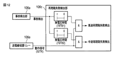
図12に再閉路失敗の検出ロジックの例を、図13に事故発生と制御実施のタイムチャートの例を示す。 FIG. 12 shows an example of detection logic for reclosing failure, and FIG. 13 shows an example of a time chart for accident occurrence and control execution.
図12に示されるように、再閉路失敗検出部106cは、事故検出部106aにより検出される事故発生のタイミングから高速再閉路の無電圧時間(79TB1)経過後に送電線保護リレー106eの動作信号(52TX)を受信した場合に、高速再閉路失敗と判定し、高速再閉路失敗検出を示す信号を出力する。また、再閉路失敗検出部106cは、事故検出部106aにより検出される事故発生のタイミングから、上記無電圧時間(79TB1)よりも長い中速再閉路(あるいは低速再閉路)の無電圧時間(79TB2)経過後に、送電線保護リレー106eの動作信号(52TX)を受信した場合に、中速再閉路失敗(あるいは低速再閉路失敗)と判定し、中速再閉路失敗検出(あるいは低速再閉路失敗検出)を示す信号を出力する。
As shown in FIG. 12, the reclosing
電制発電機決定手段105は、図13に示されるように、タイミングT0で事故が発生した後、事故種別検出手段106により事故が検知され事故種別が通知されるタイミングT1で第1段制御を実施することを決定し、これにより制御手段107が第1段制御を実施する。その後、高速再閉路失敗が検出された場合、電制発電機決定手段105は、事故種別検出手段106から高速再閉路失敗検出が通知されるタイミングT2で第2段制御を実施することを決定し、これにより制御手段107が第2段制御を実施する。その後、中速再閉路失敗が検出された場合、電制発電機決定手段105は、事故種別検出手段106から中速再閉路失敗検出が通知されるタイミングT3で第3段制御を実施することを決定し、これにより制御手段107が第3段制御を実施する。
As shown in FIG. 13, the electric power
なお、本実施形態の中央演算装置9の処理フローについては、再閉路の成功/失敗を高速再閉路と中速再閉路(あるいは低速再閉路)とで区別する点を除けば、図7に示した処理フローと同様となるため、その説明を省略する。 The processing flow of the central processing unit 9 of the present embodiment is shown in FIG. 7 except that the success / failure of the reclosing is distinguished between a high speed reclosing and a medium speed reclosing (or a low speed reclosing). Since the processing flow is the same as that described above, the description thereof is omitted.
中央演算装置9の処理完了後、演算装置10は、系統事故発生時に事故検出端末装置11から事故種別の情報を受信したときには、その事故種別を中央演算装置9から受信した制御テーブルと照合して、第1段制御で電源制限する電制発電機を決定し、制御端末装置12は、演算装置10により決定された電制発電機を電力系統から解列させる。また、演算装置10は、事故検出端末装置11から続いて高速再閉路失敗検出の通知を受信したときには、再び制御テーブルを参照し、第2段制御で電源制限する電制発電機を決定し、制御端末装置12は、演算装置10により決定された電制発電機を電力系統から解列させる。また、演算装置10は、事故検出端末装置11から続いて中速再閉路失敗検出(あるいは低速再閉路失敗検出)の通知を受信したときには、再び制御テーブルを参照し、第3段制御で電源制限する電制発電機を決定し、制御端末装置12は、演算装置10により決定された電制発電機を電力系統から解列させる。
After completion of the processing of the central processing unit 9, when the
第4の実施形態によれば、第1の実施形態の効果に加え、高速再閉路失敗時と中速再閉路失敗時(あるいは低速再閉路失敗時)との無電圧時間の違いに応じた段階的な制御を行うことができ、中速再閉路失敗時(あるいは低速再閉路失敗時)の過負荷制御などを適切に行うことができる。 According to the fourth embodiment, in addition to the effects of the first embodiment, a stage corresponding to a difference in no-voltage time between a high-speed reclosing failure and a medium-speed reclosing failure (or a low-speed reclosing failure) Control can be performed, and overload control at the time of medium speed reclosing failure (or at the time of low speed reclosing failure) can be appropriately performed.
以上詳述したように、各実施形態によれば、事前演算型の電力系統安定化システムにおいて過剰制御を防止することができる。 As described in detail above, according to each embodiment, it is possible to prevent over-control in a pre-computed power system stabilization system.
本発明のいくつかの実施形態を説明したが、これらの実施形態は、例として提示したものであり、発明の範囲を限定することは意図していない。これら新規な実施形態は、その他の様々な形態で実施されることが可能であり、発明の要旨を逸脱しない範囲で、種々の省略、置き換え、変更を行うことができる。これら実施形態やその変形は、発明の範囲や要旨に含まれるとともに、特許請求の範囲に記載された発明とその均等の範囲に含まれる。 Although several embodiments of the present invention have been described, these embodiments are presented by way of example and are not intended to limit the scope of the invention. These novel embodiments can be implemented in various other forms, and various omissions, replacements, and changes can be made without departing from the scope of the invention. These embodiments and modifications thereof are included in the scope and gist of the invention, and are included in the invention described in the claims and the equivalents thereof.
1…発電機、2…母線、3…送電線あるいは変圧器、4…遮断器(CB)、5…電流計測器(CT)、6…電圧計測器(VT)、7…事故除去リレーシステム、8…通信設備、9…中央演算装置、10…演算装置、11…事故検出端末装置、12…制御端末装置、101…系統情報収集手段、102…系統モデル作成手段、103…解析条件設定手段、103a…系統モデル記憶部、103b…想定事故種別記憶部、103c…解析条件設定部、104…安定度判定手段、104a…解析条件記憶部、104b…過渡安定度計算部、104c…安定度判定部、104d…制御テーブル設定部、105…電制発電機決定手段、105a…制御テーブル記憶部、105b…照合処理部、106…事故種別検出手段、107…制御手段。
DESCRIPTION OF SYMBOLS 1 ... Generator, 2 ... Bus line, 3 ... Transmission line or transformer, 4 ... Circuit breaker (CB), 5 ... Current measuring device (CT), 6 ... Voltage measuring device (VT), 7 ... Accident elimination relay system, DESCRIPTION OF
Claims (6)
前記中央演算装置は、系統事故が発生した際の電力系統の安定度維持に必要な制御内容として、想定される事故種別ごとに、再閉路成功を想定した制御内容と再閉路失敗を想定した制御内容とをそれぞれ求めて制御テーブルに設定し、
前記事故検出端末装置は、系統事故発生時に判定した事故種別の情報を前記演算装置へ送信するとともに、事故発生のタイミングから無電圧時間経過後に送電線保護リレーの動作信号を受信した場合に再閉路失敗と判定し再閉路失敗が検出されたことを示す信号を前記演算装置へ送信し、
前記演算装置は、初めに再閉路成功を想定した制御内容による制御を行い、再閉路失敗が検出された場合は再閉路失敗を想定した制御内容による制御を追加で行うことを決定する
ことを特徴とする電力系統安定化システム。 A central processing unit that sets information indicating a power generator necessary for maintaining the stability of the power system in the control table and transmits the control table, and determines the accident type when a system fault occurs and transmits information on the accident type An accident detection terminal device and a control table transmitted from the central processing unit and an accident type information transmitted from the accident detection terminal device are received, and the accident type is collated with the control table to control power generation. In a pre-computation type power system stabilization system comprising: an arithmetic device that determines a machine; and a control terminal device that disconnects the control generator determined by the arithmetic device from the power system,
The central processing unit, as the control content necessary for maintaining the stability of the power system when a system fault occurs, for each assumed accident type, control content assuming reclosing success and control assuming reclosing failure Each content and set it in the control table ,
The accident detection terminal device transmits information on an accident type determined at the time of occurrence of a system fault to the arithmetic device, and recloses when an operation signal of a power transmission line protection relay is received after a no-voltage time has elapsed from the timing of the accident occurrence. A signal indicating that a reclosing failure has been detected as a failure is transmitted to the arithmetic device,
The arithmetic device first performs control based on the control content assuming re-closing success, and if re-closing failure is detected, determines to additionally perform control based on the control content assuming re-closing failure. Power system stabilization system.
前記中央演算装置は、再閉路の成功/失敗を送電線の回線単位で区別し、送電線2回線に跨る系統事故が発生した際の再閉路2回線成功、再閉路1回線失敗、再閉路2回線失敗のそれぞれの場合を想定した制御内容を求めて制御テーブルに設定し、
前記演算装置は、系統事故発生時に、検出される事故種別を制御テーブルと照合して、初めに再閉路2回線成功を想定した制御内容による制御を行い、再閉路失敗が検出された場合は再閉路が失敗した回線数に応じて再閉路1回線失敗または再閉路2回線失敗を想定した制御内容による制御を追加で行うことを決定する
ことを特徴とする電力系統安定化システム。 In the electric power system stabilization system of Claim 1,
The central processing unit distinguishes the success / failure of the reclosing in units of transmission lines, and the reclosing 2 line success, reclosing 1 line failure, reclosing 2 when a system fault occurs across the 2 transmission lines. Find the control contents assuming each case of line failure, set it in the control table,
When a system fault occurs, the arithmetic device collates the detected fault type with the control table, and first performs control according to the control content assuming that the reclosing two-line success is successful. A power system stabilization system, characterized in that it is determined to additionally perform control according to control contents assuming reclosing 1 circuit failure or reclosing 2 circuit failure according to the number of circuits that have failed to be closed.
前記中央演算装置は、再閉路の成功/失敗を高速再閉路と中速再閉路あるいは低速再閉路とで区別し、系統事故が発生した際の高速再閉路成功、高速再閉路失敗、高速再閉路失敗の後の中速再閉路失敗あるいは低速再閉路失敗のそれぞれの場合を想定した制御内容を求めて制御テーブルに設定し、
前記演算装置は、系統事故発生時に、検出される事故種別を制御テーブルと照合して、初めに高速再閉路成功を想定した制御内容による制御を行い、高速再閉路失敗が検出された場合は高速再閉路失敗を想定した制御内容による制御を追加で行い、さらに中速再閉路失敗あるいは低速再閉路失敗が検出された場合は中速再閉路失敗あるいは低速再閉路失敗を想定した制御内容による制御を追加で行うことを決定することを特徴とする電力系統安定化システム。 In the electric power system stabilization system of Claim 1,
The central processing unit distinguishes success / failure of reclosing between high-speed reclosing, medium-speed reclosing, and low-speed reclosing, and high-speed reclosing success, high-speed reclosing failure, high-speed reclosing when a system fault occurs. Determine the control contents assuming each case of medium speed reclosing failure or low speed reclosing failure after failure, and set it in the control table,
When the system fault occurs, the arithmetic device collates the detected fault type with the control table, and first performs control based on the control content assuming high-speed reclosing success. Additional control based on the control details assuming reclosing failure is performed, and if medium speed reclosing failure or low speed reclosing failure is detected, control based on control details assuming medium speed reclosing failure or low speed reclosing failure is performed. A power system stabilization system characterized in that it is decided to perform additionally.
前記中央演算装置は、制御内容として電源制限する電制発電機を決定して該電制発電機を示す情報を制御テーブルに設定する処理を行うことを特徴とする電力系統安定化システム。 In the electric power system stabilization system of any one of Claims 1 thru | or 3,
The said central processing unit performs the process which determines the control generator which restrict | limits a power supply as control content, and sets the information which shows this control generator to a control table.
前記中央演算装置は、再閉路失敗を想定した電制発電機選択の処理を先に行い、電制発電機なしに電力系統の安定度維持が可能と判断した場合、再閉路成功を想定した発電機選択の処理を省略することを特徴とする電力系統安定化システム。 In the electric power system stabilization system of Claim 4,
The central processing unit first performs the control generator selection process assuming a reclosing failure, and if it is determined that the stability of the power system can be maintained without the control generator, the power generation assuming the reclosing success A power system stabilization system characterized by omitting the machine selection process.
前記中央演算装置により、系統事故が発生した際の電力系統の安定度維持に必要な制御内容として、想定される事故種別ごとに、再閉路成功を想定した制御内容と再閉路失敗を想定した制御内容とをそれぞれ求めて制御テーブルに設定しておき、
前記事故検出端末装置により、系統事故発生時に判定した事故種別の情報を前記演算装置へ送信するとともに、事故発生のタイミングから無電圧時間経過後に送電線保護リレーの動作信号を受信した場合に再閉路失敗と判定し再閉路失敗が検出されたことを示す信号を前記演算装置へ送信し、
前記演算装置により、初めに再閉路成功を想定した制御内容による制御を行い、再閉路失敗が検出された場合は再閉路失敗を想定した制御内容による制御を追加で行うことを決定する
ことを特徴とする電力系統安定化方法。 A central processing unit that sets information indicating a power generator necessary for maintaining the stability of the power system in the control table and transmits the control table, and determines the accident type when a system fault occurs and transmits information on the accident type An accident detection terminal device and a control table transmitted from the central processing unit and an accident type information transmitted from the accident detection terminal device are received, and the accident type is collated with the control table to control power generation. A power system applied to a pre-computation type power system stabilization system comprising: a computing device that determines a machine; and a control terminal device that disconnects the control generator determined by the computing device from the power system. A stabilization method,
By the central processing unit , as the control content necessary for maintaining the stability of the power system when a system fault occurs, for each assumed accident type, the control content assuming reclosing success and the control assuming reclosing failure Find the contents and set them in the control table.
When the accident detection terminal device transmits information on the type of accident determined at the time of occurrence of a system fault to the arithmetic unit, and when the operation signal of the transmission line protection relay is received after the no-voltage time has elapsed from the timing of the accident occurrence, the circuit is reclosed. A signal indicating that a reclosing failure has been detected as a failure is transmitted to the arithmetic device,
The control unit first performs control based on the control content assuming reclosing success, and when reclosing failure is detected, it is determined to additionally perform control based on the control content assuming reclosing failure. Power system stabilization method.
Priority Applications (1)
| Application Number | Priority Date | Filing Date | Title |
|---|---|---|---|
| JP2013155953A JP6219085B2 (en) | 2013-07-26 | 2013-07-26 | Power system stabilization system and power system stabilization method |
Applications Claiming Priority (1)
| Application Number | Priority Date | Filing Date | Title |
|---|---|---|---|
| JP2013155953A JP6219085B2 (en) | 2013-07-26 | 2013-07-26 | Power system stabilization system and power system stabilization method |
Publications (2)
| Publication Number | Publication Date |
|---|---|
| JP2015027199A JP2015027199A (en) | 2015-02-05 |
| JP6219085B2 true JP6219085B2 (en) | 2017-10-25 |
Family
ID=52491448
Family Applications (1)
| Application Number | Title | Priority Date | Filing Date |
|---|---|---|---|
| JP2013155953A Active JP6219085B2 (en) | 2013-07-26 | 2013-07-26 | Power system stabilization system and power system stabilization method |
Country Status (1)
| Country | Link |
|---|---|
| JP (1) | JP6219085B2 (en) |
Families Citing this family (1)
| Publication number | Priority date | Publication date | Assignee | Title |
|---|---|---|---|---|
| JP6933586B2 (en) * | 2018-01-15 | 2021-09-08 | 株式会社東芝 | Power system stabilization processing device and power system stabilization system |
Family Cites Families (8)
| Publication number | Priority date | Publication date | Assignee | Title |
|---|---|---|---|---|
| JPS5183138A (en) * | 1975-01-20 | 1976-07-21 | Hitachi Ltd | Denryokukeitono kadoanteidoseigyohoshiki |
| JPS5641725A (en) * | 1979-09-11 | 1981-04-18 | Tokyo Shibaura Electric Co | Controller for power system stabilizer |
| JPH07163054A (en) * | 1993-12-07 | 1995-06-23 | Hitachi Ltd | Series compensation control method for power system and series compensation device used therefor |
| JP3504471B2 (en) * | 1997-09-19 | 2004-03-08 | 三菱電機株式会社 | Power supply stabilization control method and device |
| JP3207388B2 (en) * | 1998-04-17 | 2001-09-10 | 株式会社東芝 | Power system protection control device, power system monitoring and control system, and storage medium storing program |
| JP2000125460A (en) * | 1998-10-16 | 2000-04-28 | Toshiba Corp | Reclose circuit of protective relay |
| JP2001078354A (en) * | 1999-09-06 | 2001-03-23 | Meidensha Corp | Fault determination method for power distribution wire |
| JP5424760B2 (en) * | 2009-07-17 | 2014-02-26 | 三菱電機株式会社 | Grid stabilization system |
-
2013
- 2013-07-26 JP JP2013155953A patent/JP6219085B2/en active Active
Also Published As
| Publication number | Publication date |
|---|---|
| JP2015027199A (en) | 2015-02-05 |
Similar Documents
| Publication | Publication Date | Title |
|---|---|---|
| US20200412167A1 (en) | Method and system for fast reconfiguration of power supply network in tens of milliseconds after power grid failure | |
| Leterme et al. | A local backup protection algorithm for HVDC grids | |
| US11128127B2 (en) | FLISR without communication | |
| JP2023177101A (en) | Power system stabilization device, computer program for power system stabilization device, and power system stabilization method | |
| US11611210B2 (en) | Tie switch restoration | |
| CN110783946B (en) | Method for locating phase faults in microgrids | |
| US11329479B2 (en) | Locating and isolating grid faults utilizing a fast close-open operation | |
| Sharafi et al. | Transmission system wide-area back-up protection using current phasor measurements | |
| CN109274078B (en) | A method, device and equipment for a line fault stability control criterion of a safety and stability control device | |
| Chandraratne et al. | Smart grid protection through self-healing | |
| Liu et al. | A simple multi agent system based adaptive relay setting strategy for distribution system with wind generation integration | |
| Tasdighi et al. | Impact analysis of network topology change on transmission distance relay settings | |
| CN106684822A (en) | Transformer dead-zone fault protection method and breaker failure protection method | |
| Das et al. | Real-time secured third zone relay operation under dynamic stressed conditions | |
| US11728638B2 (en) | Normally open tie pulse testing | |
| JP6219085B2 (en) | Power system stabilization system and power system stabilization method | |
| CN108345706A (en) | A kind of emulation mode that power supply is cut soon and model | |
| CN106300302A (en) | A kind of distribution protection method | |
| JP5728289B2 (en) | Power system stabilization system, power system stabilization method, and power system stabilization program | |
| CN110768219A (en) | GIL-overhead mixed line protection method and system | |
| Vijitha et al. | Short circuit analysis and adaptive zonal protection of distribution system with distributed generators | |
| JP7163163B2 (en) | Power system stabilization system | |
| CN116780639A (en) | A distributed photovoltaic grid-connected control method, device and storage medium | |
| Pordanjani et al. | Risk reduction in special protection systems by using an online method for transient instability prediction | |
| JP5889935B2 (en) | Power supply system overload mitigation system and power failure elimination method |
Legal Events
| Date | Code | Title | Description |
|---|---|---|---|
| A621 | Written request for application examination |
Free format text: JAPANESE INTERMEDIATE CODE: A621 Effective date: 20160721 |
|
| A977 | Report on retrieval |
Free format text: JAPANESE INTERMEDIATE CODE: A971007 Effective date: 20170421 |
|
| A131 | Notification of reasons for refusal |
Free format text: JAPANESE INTERMEDIATE CODE: A131 Effective date: 20170425 |
|
| A521 | Written amendment |
Free format text: JAPANESE INTERMEDIATE CODE: A523 Effective date: 20170620 |
|
| TRDD | Decision of grant or rejection written | ||
| A01 | Written decision to grant a patent or to grant a registration (utility model) |
Free format text: JAPANESE INTERMEDIATE CODE: A01 Effective date: 20170829 |
|
| A61 | First payment of annual fees (during grant procedure) |
Free format text: JAPANESE INTERMEDIATE CODE: A61 Effective date: 20170927 |
|
| R150 | Certificate of patent or registration of utility model |
Ref document number: 6219085 Country of ref document: JP Free format text: JAPANESE INTERMEDIATE CODE: R150 |
|
| S111 | Request for change of ownership or part of ownership |
Free format text: JAPANESE INTERMEDIATE CODE: R313115 |
|
| R350 | Written notification of registration of transfer |
Free format text: JAPANESE INTERMEDIATE CODE: R350 |