JP6219081B2 - refrigerator - Google Patents

refrigerator Download PDF

Info

Publication number
JP6219081B2
JP6219081B2 JP2013145713A JP2013145713A JP6219081B2 JP 6219081 B2 JP6219081 B2 JP 6219081B2 JP 2013145713 A JP2013145713 A JP 2013145713A JP 2013145713 A JP2013145713 A JP 2013145713A JP 6219081 B2 JP6219081 B2 JP 6219081B2
Authority
JP
Japan
Prior art keywords
water
water storage
storage unit
refrigerator
supply
Prior art date
Legal status (The legal status is an assumption and is not a legal conclusion. Google has not performed a legal analysis and makes no representation as to the accuracy of the status listed.)
Expired - Fee Related
Application number
JP2013145713A
Other languages
Japanese (ja)
Other versions
JP2015017765A (en
Inventor
尚宏 兼坂
尚宏 兼坂
尾崎 達哉
達哉 尾崎
及川 巧
巧 及川
英司 品川
英司 品川
Current Assignee (The listed assignees may be inaccurate. Google has not performed a legal analysis and makes no representation or warranty as to the accuracy of the list.)
Toshiba Lifestyle Products and Services Corp
Original Assignee
Toshiba Lifestyle Products and Services Corp
Priority date (The priority date is an assumption and is not a legal conclusion. Google has not performed a legal analysis and makes no representation as to the accuracy of the date listed.)
Filing date
Publication date
Application filed by Toshiba Lifestyle Products and Services Corp filed Critical Toshiba Lifestyle Products and Services Corp
Priority to JP2013145713A priority Critical patent/JP6219081B2/en
Publication of JP2015017765A publication Critical patent/JP2015017765A/en
Application granted granted Critical
Publication of JP6219081B2 publication Critical patent/JP6219081B2/en
Expired - Fee Related legal-status Critical Current
Anticipated expiration legal-status Critical

Links

Images

Description

本発明の実施形態は、冷蔵庫に関する。   Embodiments of the present invention relate to a refrigerator.

一部の冷蔵庫には、内部の酸素濃度を低減させることができる減酸素室が設けられている(例えば特許文献1)。減酸素室の中に食品を保存すると、その食品の酸化を抑えることができる。   Some refrigerators are provided with an oxygen reduction chamber capable of reducing the oxygen concentration inside (for example, Patent Document 1). If food is stored in a hypoxic chamber, oxidation of the food can be suppressed.

酸素濃度の低減は、減酸素室に接続された減酸素装置によって行われる。減酸素装置は、減酸素室外の空気に接するアノード(陽極)と、減酸素室内の空気に接するカソード(陰極)と、アノードとカソードとに挟持された高分子電解質膜とを備える。アノードとカソードの間に電圧が印加されると、次の反応が生じる。   The oxygen concentration is reduced by an oxygen reduction apparatus connected to the oxygen reduction chamber. The oxygen reduction device includes an anode (anode) in contact with air outside the oxygen reduction chamber, a cathode (cathode) in contact with air in the oxygen reduction chamber, and a polymer electrolyte membrane sandwiched between the anode and the cathode. When a voltage is applied between the anode and cathode, the following reaction occurs.

アノード 2HO → 4H + 4e + O・・・(a)
カソード 4H + 4e + O → 2HO・・・(b)
つまり、アノード側では水が分解して酸素と水素イオンが発生する。この水素イオンが高分子電解質膜を通ってカソード側へ浸透し、カソード側の酸素と結合して水となる。結果として、カソード側の酸素をアノード側へ移動させることになる。これにより、減酸素室内の酸素濃度を低減させる。
Anode 2H 2 O → 4H + + 4e + O 2 (a)
Cathode 4H + + 4e + O 2 → 2H 2 O (b)
That is, on the anode side, water is decomposed and oxygen and hydrogen ions are generated. The hydrogen ions permeate the cathode side through the polymer electrolyte membrane, and combine with oxygen on the cathode side to become water. As a result, the oxygen on the cathode side is moved to the anode side. Thereby, the oxygen concentration in the oxygen reduction chamber is reduced.

ところで、一般に、減酸素装置は、アノードとカソードとの間に一定の電流が流れるように電圧が制御される。しかし、アノード側に供給される水が不足した場合、通常の電圧では、アノード側で電子が発生せず一定の電流が流れない。そこで、冷蔵庫の制御部は、一定の電流を流すために、アノードとカソードとの間の電圧を上げる。すると、アノードとカソードとの間の高分子電解質膜が発熱し、高分子電解質膜が劣化する。   By the way, in general, in the oxygen reduction device, the voltage is controlled so that a constant current flows between the anode and the cathode. However, when the water supplied to the anode side is insufficient, at a normal voltage, electrons are not generated on the anode side and a constant current does not flow. Therefore, the control unit of the refrigerator raises the voltage between the anode and the cathode in order to flow a constant current. Then, the polymer electrolyte membrane between the anode and the cathode generates heat, and the polymer electrolyte membrane deteriorates.

特開2011−202898号公報JP 2011-202898 A

本発明が解決しようとする課題は、アノード側に供給される水が不足した場合であっても、高分子電解質膜の劣化を防ぐことができる冷蔵庫を提供することである。   The problem to be solved by the present invention is to provide a refrigerator capable of preventing deterioration of the polymer electrolyte membrane even when water supplied to the anode side is insufficient.

実施形態の冷蔵庫は、減酸素室と、前記減酸素室外の空気に接するアノードと、前記減酸素室内の空気に接するカソードと、前記アノードと前記カソードとの間に挟持される高分子電解質膜と、前記アノードに供給する水を溜める貯水部と、前記貯水部の水が一定量以下となったことを検知する水位検知手段とを備え、前記アノードと前記カソードとの間に電圧が印加されることにより、前記アノードにおいて水が分解されて水素イオンが発生するとともに、前記高分子電解質膜内を移動した前記水素イオンが前記カソードにおいて酸素と結合することにより、前記減酸素室内の酸素濃度が低減される冷蔵庫であって、前記水位検知手段により前記貯水部の水が一定量以下となったことが検知された場合に電圧の印加が止まることを特徴とする。   The refrigerator according to the embodiment includes an oxygen reduction chamber, an anode in contact with air outside the oxygen reduction chamber, a cathode in contact with air in the oxygen reduction chamber, and a polymer electrolyte membrane sandwiched between the anode and the cathode. A reservoir for storing water to be supplied to the anode, and water level detecting means for detecting that the amount of water in the reservoir is less than a certain amount, and a voltage is applied between the anode and the cathode. As a result, water is decomposed at the anode to generate hydrogen ions, and the hydrogen ions moved through the polymer electrolyte membrane are combined with oxygen at the cathode, thereby reducing the oxygen concentration in the oxygen-reducing chamber. The application of the voltage is stopped when the water level detecting means detects that the water in the water storage section is below a certain amount. .

実施形態の冷蔵庫の断面図。Sectional drawing of the refrigerator of embodiment. 冷蔵室の要部を示す正面図。The front view which shows the principal part of a refrigerator compartment. 図2のA−A断面図。AA sectional drawing of FIG. 図3のB−B断面図。BB sectional drawing of FIG. 図3のC−C線断面図。CC sectional view taken on the line of FIG. 図3のD−D線断面図。The DD sectional view taken on the line of FIG. 減酸素装置の断面図。Sectional drawing of an oxygen reduction apparatus. 減酸素ユニットの分解斜視図。The disassembled perspective view of an oxygen reduction unit. 収納室に取り付けられた減酸素ユニットの背面図。The rear view of the oxygen reduction unit attached to the storage chamber. 背面から見た給水装置の縦断面図。The longitudinal cross-sectional view of the water supply apparatus seen from the back. 収納室及び蒸発器カバーを取り外した状態の冷蔵空間の正面図。The front view of the refrigerated space of the state which removed the storage chamber and the evaporator cover.

本発明の実施の形態を図面に基づいて説明する。   Embodiments of the present invention will be described with reference to the drawings.

(1)冷蔵庫10の全体構造
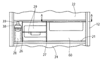
本実施形態の冷蔵庫10は、図1に示すように、外郭を形成する外箱と貯蔵空間を形成する内箱との間に断熱材を配設した前面に開口する冷蔵庫本体12を備える。冷蔵庫本体12内部は、断熱仕切壁14によって上方の冷蔵空間20と下方の冷凍空間40とに区画されている。
(1) Overall Structure of Refrigerator 10 As shown in FIG. 1, the refrigerator 10 of the present embodiment has an opening in the front surface in which a heat insulating material is disposed between an outer box that forms an outer shell and an inner box that forms a storage space. The refrigerator main body 12 is provided. The interior of the refrigerator main body 12 is partitioned into an upper refrigerated space 20 and a lower refrigerated space 40 by a heat insulating partition wall 14.

冷蔵空間20は、冷蔵温度(例えば、2〜3℃)に冷却される空間である。冷蔵空間20の内部は仕切板21によって上下に区画され、仕切板21の上方に複数段の載置棚を有する冷蔵室22が設けられ、仕切板21の下方に引き出し式の収納容器25が配置された野菜室24が設けられている。   The refrigerated space 20 is a space that is cooled to a refrigeration temperature (for example, 2 to 3 ° C.). The inside of the refrigerated space 20 is partitioned vertically by a partition plate 21, a refrigerator compartment 22 having a plurality of stages of mounting shelves is provided above the partition plate 21, and a drawer-type storage container 25 is disposed below the partition plate 21. A vegetable room 24 is provided.

図2に示すように、冷蔵室22の仕切板21の直上の空間が、2つの縦仕切壁26、27によって冷蔵庫幅方向に3つの空間に区画されている。具体的には、縦仕切壁26が冷蔵室22の左側の側壁に寄せて配設され、縦仕切壁27が冷蔵庫幅方向中央部付近に配設されている。冷蔵室22の左側の側壁と縦仕切壁26に挟まれた空間には、製氷用水を貯水する製氷用タンク28が配設されている。縦仕切壁26と縦仕切壁27に挟まれた空間には、引き出し式の収納容器29が上下2段に重ねて配設されている。縦仕切壁27と冷蔵室22の右側の側壁に挟まれた空間には、減酸素室60が設けられている。   As shown in FIG. 2, the space immediately above the partition plate 21 of the refrigerator compartment 22 is divided into three spaces in the refrigerator width direction by two vertical partition walls 26 and 27. Specifically, the vertical partition wall 26 is disposed close to the left side wall of the refrigerator compartment 22, and the vertical partition wall 27 is disposed in the vicinity of the central portion in the refrigerator width direction. An ice making tank 28 for storing ice making water is disposed in a space sandwiched between the left side wall and the vertical partition wall 26 of the refrigerator compartment 22. In a space sandwiched between the vertical partition wall 26 and the vertical partition wall 27, drawer-type storage containers 29 are arranged in two upper and lower stages. An oxygen reduction chamber 60 is provided in a space between the vertical partition wall 27 and the right side wall of the refrigerator compartment 22.

縦仕切壁27と冷蔵室22の右側壁に挟まれた空間に設けられた減酸素室60は、図3〜図5に示すように、仕切板21の上面に固定される減酸素容器62と、減酸素容器62内に収納される引出容器64とを備える。減酸素容器62は、前面が開口する直方体状の箱体からなり、前面の開口部が引出容器64の前板を兼ねた扉66によって閉塞されている。引出容器64は、左右両側面の後部に設けられたローラ65が、減酸素容器62の内側に設けられたレール67を摺動することで、減酸素容器62に対して前後方向に引出し可能となっている。   As shown in FIGS. 3 to 5, the oxygen reduction chamber 60 provided in the space between the vertical partition wall 27 and the right side wall of the refrigerator compartment 22 includes an oxygen reduction container 62 fixed to the upper surface of the partition plate 21. And an extraction container 64 housed in the oxygen reduction container 62. The oxygen reduction container 62 is formed of a rectangular parallelepiped box having a front opening, and the opening on the front is closed by a door 66 that also serves as a front plate of the drawer container 64. The drawer container 64 can be pulled out in the front-rear direction with respect to the oxygen reduction container 62 by a roller 65 provided at the rear of both left and right side surfaces sliding on a rail 67 provided inside the oxygen reduction container 62. It has become.

野菜室24の下方に配置した冷凍空間40は、冷凍温度(例えば、−18℃以下)に冷却される空間であって、上部に製氷装置23を備えた製氷室42と小型冷凍室とが左右に併設され、その下方に冷凍室46が設けられている。製氷装置23には製氷用タンク28内の水が供給される。   The freezing space 40 disposed below the vegetable room 24 is a space cooled to a freezing temperature (for example, −18 ° C. or lower), and the ice making room 42 having the ice making device 23 on the upper side and the small freezing room are left and right. And a freezer compartment 46 is provided therebelow. Water in the ice making tank 28 is supplied to the ice making device 23.

冷蔵室22の開口部は、冷蔵庫本体12の一側部の上下に設けられたヒンジにより回動自在に枢支された冷蔵室扉22aにより閉塞されている。   The opening of the refrigerator compartment 22 is closed by a refrigerator compartment door 22a pivotally supported by hinges provided above and below one side of the refrigerator body 12.

野菜室24、製氷室42、小型冷凍室および冷凍室46の開口部は、引き出し式扉24a,42a,46aにより閉塞されている。各引き出し式扉24a,42a,46aの裏面側に固着した左右一対の支持枠には、収納容器25,43,47が保持されており、開扉動作とともに庫外に引き出されるように構成されている。   Openings of the vegetable compartment 24, the ice making compartment 42, the small freezer compartment and the freezer compartment 46 are closed by drawer doors 24a, 42a and 46a. The pair of left and right support frames fixed to the back side of each pull-out door 24a, 42a, 46a holds the storage containers 25, 43, 47, and is configured to be pulled out of the cabinet as the door opens. Yes.

冷蔵庫本体12の背面底部には、機械室50が設けられ、冷凍サイクルを構成する圧縮機51などが載置されている。この機械室50の背面上部には、冷蔵庫10の動作を制御する制御部(不図示)が設けられている。   A machine room 50 is provided at the bottom of the back surface of the refrigerator main body 12, and a compressor 51 and the like constituting the refrigeration cycle are placed thereon. A control unit (not shown) for controlling the operation of the refrigerator 10 is provided on the upper back of the machine room 50.

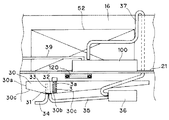
減酸素室60の後方から野菜室24の後方にわたって蒸発器カバー16が設けられている。蒸発器カバー16と冷蔵庫本体12の背面との間に蒸発器室18が区画形成されている。蒸発器室18内には、上から順に、冷蔵用蒸発器52、樋30、冷蔵用ファン53が配設されている。また、蒸発器カバー16と冷蔵用蒸発器52との間には断熱材16bが配設されている。樋30は、除霜運転時に冷蔵用蒸発器52から生じる除霜水を受ける。冷蔵用ファン53は、蒸発器室18内の冷気を冷蔵空間20内へ循環させる。   An evaporator cover 16 is provided from the rear of the oxygen reduction chamber 60 to the rear of the vegetable chamber 24. An evaporator chamber 18 is defined between the evaporator cover 16 and the back surface of the refrigerator main body 12. In the evaporator chamber 18, a refrigeration evaporator 52, a basket 30, and a refrigeration fan 53 are disposed in order from the top. Further, a heat insulating material 16 b is disposed between the evaporator cover 16 and the refrigeration evaporator 52. The eaves 30 receive defrosted water generated from the refrigeration evaporator 52 during the defrosting operation. The refrigeration fan 53 circulates the cool air in the evaporator chamber 18 into the refrigeration space 20.

冷蔵用蒸発器52とこれに当たる空気との間で熱交換が行われ、冷蔵用蒸発器52の周囲に冷気が発生する。冷蔵用蒸発器52で発生した冷気は、冷蔵用ファン53の回転駆動によって、冷蔵室22及び野菜室24に導入される。これにより冷蔵空間20が所定温度に冷却される。冷蔵空間20内を循環した冷気は、吸込口から再び蒸発器室18に戻される。   Heat exchange is performed between the refrigeration evaporator 52 and the air hitting it, and cold air is generated around the refrigeration evaporator 52. The cold air generated in the refrigeration evaporator 52 is introduced into the refrigeration room 22 and the vegetable room 24 by the rotational drive of the refrigeration fan 53. Thereby, the refrigerated space 20 is cooled to a predetermined temperature. The cold air circulated in the refrigerated space 20 is returned again to the evaporator chamber 18 from the suction port.

冷凍空間40の背面には、蒸発器カバー17と冷蔵庫本体12の背面との間に蒸発器室19が区画形成されている。蒸発器室19の内には、上から順に、冷凍用ファン55と冷凍用蒸発器54が配設されている。冷凍用ファン55の回転駆動によって、冷凍用蒸発器54で発生した冷気は、製氷室42、小型冷凍室、及び冷凍室46に導入され、冷凍空間40が所定温度に冷却される。その後冷気は、吸込口から再び蒸発器室19に戻される。   On the back surface of the freezing space 40, an evaporator chamber 19 is defined between the evaporator cover 17 and the back surface of the refrigerator body 12. In the evaporator chamber 19, a refrigeration fan 55 and a refrigeration evaporator 54 are arranged in order from the top. By the rotational drive of the freezing fan 55, the cold air generated in the freezing evaporator 54 is introduced into the ice making room 42, the small freezing room, and the freezing room 46, and the freezing space 40 is cooled to a predetermined temperature. Thereafter, the cool air is returned to the evaporator chamber 19 from the suction port.

冷蔵用蒸発器52及び冷凍用蒸発器54は、機械室50に設けられた圧縮機51や凝縮器(不図示)や切替弁(不図示)とともに冷凍サイクルを構成し、圧縮機51から吐出されて循環する冷媒によって冷却される。   The refrigeration evaporator 52 and the refrigeration evaporator 54 constitute a refrigeration cycle together with a compressor 51, a condenser (not shown) and a switching valve (not shown) provided in the machine room 50, and are discharged from the compressor 51. Cooled by the circulating refrigerant.

(2)樋30の構造
図4、5、11に示すように、冷蔵用蒸発器52の下方に樋30が配置されている。
(2) Structure of casket 30 As shown in FIGS. 4, 5, and 11, the casket 30 is disposed below the refrigeration evaporator 52.

樋30は、側壁30aから底面30bに向かって低くなるように傾斜する傾斜面30cによって側壁30aと底面30bとが接続されている。   The side wall 30a and the bottom face 30b are connected by the inclined surface 30c which inclines so that it may become low toward the bottom face 30b from the side wall 30a.

樋30の底面30bには、排水口31及び吸込口32が底面30bを貫通して設けられ、排水口31の周囲を取り囲むように環状のリブ33が底面30bから上方へ突出している。つまり、環状のリブ33は、排水口31と吸込口32との間を仕切っており、吸込口32が環状のリブ33の外側に配置されている。   A drain port 31 and a suction port 32 are provided on the bottom surface 30b of the trough 30 so as to penetrate the bottom surface 30b, and an annular rib 33 projects upward from the bottom surface 30b so as to surround the periphery of the drain port 31. That is, the annular rib 33 partitions the drain port 31 and the suction port 32, and the suction port 32 is disposed outside the annular rib 33.

排水口31には、排水ホース34が接続されており、樋30で受けた除霜水が排水ホース34を介して機械室50内に設けられた蒸発皿56へ排出される。   A drainage hose 34 is connected to the drainage port 31, and defrosted water received by the gutter 30 is discharged via the drainage hose 34 to an evaporation tray 56 provided in the machine room 50.

図5及び図11に示すように、樋30の下方には、水の供給手段(第1の供給手段)としての給水ポンプ36が配設されている。樋30の底面に設けられた吸込口32が吸込ホース35を介して給水ポンプ36の吸込側に接続されている。また、吐出側が給水ホース37を介して減酸素装置70の下方に配置された給水装置100に接続されている。これにより、蒸発器樋30で受けた冷蔵用蒸発器52の除霜水を、吸込口32から吸込ホース35を介して吸い込み、給水ホース37を介して給水装置100へ給水することが可能となっている。   As shown in FIGS. 5 and 11, a water supply pump 36 serving as a water supply means (first supply means) is disposed below the eaves 30. A suction port 32 provided on the bottom surface of the gutter 30 is connected to the suction side of the water supply pump 36 via a suction hose 35. In addition, the discharge side is connected to a water supply device 100 disposed below the oxygen reduction device 70 via a water supply hose 37. As a result, the defrosted water of the refrigeration evaporator 52 received by the evaporator bowl 30 can be sucked from the suction port 32 via the suction hose 35 and supplied to the water supply device 100 via the water supply hose 37. ing.

また、樋30には、上方から樋30の底面30b付近にかけてチューブ3aが配置されている。チューブ3aの下端は開口しており、該開口から水が出入りする。そのため、チューブ3a内の水面は、チューブ3a外の水面と、同じ高さになる。チューブ3aの内部には、渇水検知用温度センサ3が配されている。渇水検知用温度センサ3の温度測定部である先端は、予め定められた樋渇水高さよりわずかに高い位置に配置されている。樋30の水面が樋渇水高さまで下がり、渇水検知用温度センサ3の先端が水中から水面上に出ると、測定される温度が水の温度から空気の温度に変化する。これにより、樋30の水面が樋渇水高さまで低くなったことを検知する。樋渇水高さは、樋30内の水の量が一定量となった時の水面の高さである。この一定量は、冷蔵庫の設計等に応じて予め定められている量で、例えば、給水ポンプ36が後述するように一定時間稼働した場合に、樋30から貯水部103へ供給される水の量である。   Moreover, the tube 3a is arrange | positioned from the upper part to the bottom face 30b vicinity of the collar 30 in the collar 30. FIG. The lower end of the tube 3a is open, and water enters and exits from the opening. Therefore, the water surface in the tube 3a becomes the same height as the water surface outside the tube 3a. A drought detection temperature sensor 3 is arranged inside the tube 3a. The tip which is the temperature measurement part of the drought detection temperature sensor 3 is disposed at a position slightly higher than a predetermined drought water height. When the water surface of the dredger 30 falls to the drought water level and the tip of the drought detection temperature sensor 3 comes out of the water onto the water surface, the measured temperature changes from the water temperature to the air temperature. Thereby, it detects that the water surface of the dredging 30 became low to the drought water level. The drought water height is the height of the water surface when the amount of water in the tub 30 becomes a constant amount. This fixed amount is a predetermined amount according to the design of the refrigerator, for example, the amount of water supplied from the dredger 30 to the water storage unit 103 when the water supply pump 36 operates for a fixed time as will be described later. It is.

(3)減酸素装置70の構造
減酸素容器62の背面には、収納室60内の酸素を減少させる減酸素装置70が設けられている。
(3) Structure of Oxygen Reduction Device 70 On the back surface of the oxygen reduction container 62, an oxygen reduction device 70 that reduces oxygen in the storage chamber 60 is provided.

減酸素装置70は、図7に示すように、断熱材78で外側を覆われた上で、箱型のユニットケース76の内部に収納されている。ユニットケース76は、減酸素容器62の背面に設けられた開口部80を覆うように減酸素容器62の背面に固定され、開口部80を介して減酸素室60内部とユニットケース76内部とが連通している。また、ユニットケース76及び断熱材78の背面には、酸素を拡散させる排気口82が開口している。   As shown in FIG. 7, the oxygen reduction device 70 is covered inside a box-shaped unit case 76 after being covered with a heat insulating material 78. The unit case 76 is fixed to the back surface of the oxygen reducing container 62 so as to cover the opening 80 provided on the back surface of the oxygen reducing container 62, and the inside of the oxygen reducing chamber 60 and the inside of the unit case 76 are connected via the opening 80. Communicate. In addition, an exhaust port 82 for diffusing oxygen is opened on the back surface of the unit case 76 and the heat insulating material 78.

減酸素装置70は、高分子電解質膜83と、高分子電解質膜83の後部に設けられたアノード(陽極)層84と、高分子電解質膜83の前部に設けられたカソード(陰極)層85とを備える。なお、図7及び図8において、実際の各部材の厚みは薄いものであるが、説明を判り易くするために、図面ではその厚みを拡大して記載している。   The oxygen reduction device 70 includes a polymer electrolyte membrane 83, an anode (anode) layer 84 provided at the rear portion of the polymer electrolyte membrane 83, and a cathode (cathode) layer 85 provided at the front portion of the polymer electrolyte membrane 83. With. 7 and 8, the actual thickness of each member is thin, but in order to make the explanation easy to understand, the thickness is enlarged in the drawings.

高分子電解質膜83は、例えば、ナフィオンで形成されている。ナフィオンは、スルホン化されたテトラフルオロエチレンをもとにしたフッ素樹脂の共重合体で、イオン電導性を持つポリマーであり、内部を陽イオンだけが移動して、陰イオンや電子はナフィオン内を移動しない。   The polymer electrolyte membrane 83 is made of, for example, Nafion. Nafion is a copolymer of fluororesin based on sulfonated tetrafluoroethylene, and is a polymer with ionic conductivity. Only cations move inside, and anions and electrons move inside Nafion. Do not move.

アノード層84及びカソード層85は白金を含む触媒が担持されたカーボン触媒とカーボンペーパを積層してなる。アノード層84及びカソード層85の間に高分子電解質膜83が挟持された状態で、ホットプレスなどにより一体に接合されている。   The anode layer 84 and the cathode layer 85 are formed by laminating a carbon catalyst on which a catalyst containing platinum is supported and carbon paper. The polymer electrolyte membrane 83 is sandwiched between the anode layer 84 and the cathode layer 85 and is integrally joined by hot pressing or the like.

高分子電解質膜83を挟持するアノード層84及びカソード層85の外側には、一対の集電体86,87が配設され、一対の集電体86,87の更に外側に撥水層88,89が配設され、アノード層84側の撥水層88の外側に給水体90が配設され、これらが一対の固定部材91、92によって挟持されユニット化されている。   A pair of current collectors 86 and 87 are disposed outside the anode layer 84 and the cathode layer 85 sandwiching the polymer electrolyte membrane 83, and the water repellent layer 88 and 87 are disposed further outside the pair of current collectors 86 and 87. 89 is disposed, and a water supply body 90 is disposed outside the water-repellent layer 88 on the anode layer 84 side, and these are sandwiched by a pair of fixing members 91 and 92 to form a unit.

一対の集電体86,87は、表面に白金メッキを行なったメッシュ状のチタン膜からなり、外部の電源装置に接続されており、集電体86がアノード層84にプラス通電を行い、集電体87がカソード層85にマイナス通電を行い、アノード層84とカソード層85との間に電圧を印加する。また、両集電体86,87の接触による短絡を防止するため、両集電体86,87間には絶縁体93が設けられている。この絶縁体93は、高分子電解質膜83を挟持するアノード層84及びカソード層85の周囲を取り囲む額縁状に設けられている。   The pair of current collectors 86 and 87 is made of a mesh-like titanium film having a surface plated with platinum, and is connected to an external power supply. The current collector 86 conducts positive current to the anode layer 84 to collect current. The electric conductor 87 applies a negative current to the cathode layer 85 and applies a voltage between the anode layer 84 and the cathode layer 85. Further, an insulator 93 is provided between the current collectors 86 and 87 in order to prevent a short circuit due to contact between the current collectors 86 and 87. The insulator 93 is provided in a frame shape surrounding the anode layer 84 and the cathode layer 85 that sandwich the polymer electrolyte membrane 83.

撥水層88,89は、PTE(ポリエステル)フィルムやPTFE(ポリテトラフルオロエチレン)フィルムや撥水性樹脂を用いた布帛、あるいは撥水処理が施されたカーボンペーパなどの水を透過せずに水蒸気を透過させる膜体からなり、撥水層88,89の周縁部にガスケット94,95が設けられている。アノード層84側の撥水層88は、給水体90から液体の水がアノード層84へ進入するのを防止しつつ、水蒸気を給水体90からアノード層84側へ供給する。カソード層85側の撥水層89は、カソード層85で発生した水が減酸素容器62内部へ流出するのを防止する。撥水層88,89は、水蒸気だけでなく、酸素をはじめとする気体も通過できる。   The water repellent layers 88 and 89 are water vapor that does not transmit water such as a PTE (polyester) film, a PTFE (polytetrafluoroethylene) film, a fabric using a water repellent resin, or a carbon paper subjected to a water repellent treatment. The gasket 94,95 is provided in the peripheral part of the water-repellent layers 88,89. The water repellent layer 88 on the anode layer 84 side supplies water vapor from the water supply body 90 to the anode layer 84 side while preventing liquid water from entering the anode layer 84 from the water supply body 90. The water repellent layer 89 on the cathode layer 85 side prevents water generated in the cathode layer 85 from flowing out into the oxygen reduction container 62. The water repellent layers 88 and 89 can pass not only water vapor but also gas such as oxygen.

アノード層84側の撥水層89の後方に配設された給水体90は、例えば、合成樹脂繊維より形成されたシート状の不織布からなり、好ましくは、減酸素装置70の稼働時の温度以上のガラス転移温度を持った合成樹脂繊維(例えば、ポリプロピレン)が用いられる。図7及び図9に示すように、シート状の給水体90の下部は、ユニットケース76から下方に垂れ下がり、減酸素装置70の下方に配置された給水装置100に挿入されている。給水体90のユニットケース76から垂れ下がる部分は、先端部を残して給水体カバー98で覆われている。   The water supply body 90 disposed behind the water-repellent layer 89 on the anode layer 84 side is made of, for example, a sheet-like non-woven fabric formed from synthetic resin fibers, and is preferably at or above the temperature during operation of the oxygen reduction device 70. A synthetic resin fiber having a glass transition temperature of (for example, polypropylene) is used. As shown in FIGS. 7 and 9, the lower portion of the sheet-like water supply body 90 hangs down from the unit case 76 and is inserted into the water supply device 100 disposed below the oxygen reduction device 70. The portion of the water supply body 90 that hangs down from the unit case 76 is covered with a water supply body cover 98 leaving the tip.

一対の固定部材91,92は、上記のように積層された高分子電解質膜83、アノード層84、カソード層85、集電体86,87、絶縁体93、撥水層88,89、給水体90を挟持して固定する。アノード層84側に配設された固定部材91は、直方体形状を成し、図7に示すように、ユニットケース76及び断熱材78の排気口82に対応した位置に前後方向に貫通する排気口96が設けられている。アノード層84は、集電体86のメッシュ孔、撥水層88の微細孔、及び排気口96を通じて、減酸素室60外の空気と接している。   The pair of fixing members 91 and 92 includes the polymer electrolyte membrane 83, the anode layer 84, the cathode layer 85, the current collectors 86 and 87, the insulator 93, the water repellent layers 88 and 89, and the water supply body laminated as described above. Clamp 90 and fix. The fixing member 91 disposed on the anode layer 84 side has a rectangular parallelepiped shape, and as illustrated in FIG. 7, an exhaust port penetrating in the front-rear direction at a position corresponding to the exhaust port 82 of the unit case 76 and the heat insulating material 78. 96 is provided. The anode layer 84 is in contact with the air outside the oxygen reduction chamber 60 through the mesh holes of the current collector 86, the micro holes of the water repellent layer 88, and the exhaust port 96.

カソード層85側に配設された固定部材92は、直方体形状を成し、減酸素容器62の背面に設けられた開口部80に対応する位置に前後方向に貫通する吸気口97が設けられている。この吸気口97は、上下方向に細長く延びる複数のスリットから構成されている。カソード層85は、集電体87のメッシュ孔、撥水層89の微細孔、及び吸気口97を通じて、減酸素室60内の空気と接している。   The fixing member 92 disposed on the cathode layer 85 side has a rectangular parallelepiped shape, and an intake port 97 penetrating in the front-rear direction is provided at a position corresponding to the opening 80 provided on the back surface of the oxygen reduction container 62. Yes. The air inlet 97 is composed of a plurality of slits extending in the vertical direction. The cathode layer 85 is in contact with the air in the oxygen reduction chamber 60 through the mesh holes of the current collector 87, the fine holes of the water repellent layer 89, and the air inlet 97.

以上の構造の減酸素装置70は、次のように稼働する。   The oxygen reducing device 70 having the above structure operates as follows.

後述する給水装置100の貯水部103に溜まった水が、給水体90を伝って上方へ吸い上げられる。そして、撥水層88の外側まで吸い上げられると、そこで気化して水蒸気となる。この水蒸気は、撥水層88を通過してアノード層84に供給される。   Water accumulated in a water storage unit 103 of the water supply device 100 described later is sucked upward through the water supply body 90. And if it sucks up to the outer side of the water repellent layer 88, it will vaporize and it will become water vapor | steam there. The water vapor passes through the water repellent layer 88 and is supplied to the anode layer 84.

減酸素装置70の稼働中、アノード層84とカソード層85の間には、一定の電流が流れるように、電圧が印加されている。アノード層84に供給された水(水蒸気の状態)が分解されて、水素イオン及び酸素分子が発生する((a)式)。発生した水素イオンは、高分子電解質膜83内に浸透してカソード層85へ移動し、カソード層85側の酸素分子と結合して水となる((b)式)。これにより、カソード層85側である減酸素室60内の酸素濃度が低減される。   During operation of the oxygen reduction device 70, a voltage is applied between the anode layer 84 and the cathode layer 85 so that a constant current flows. Water (steam state) supplied to the anode layer 84 is decomposed to generate hydrogen ions and oxygen molecules (formula (a)). The generated hydrogen ions penetrate into the polymer electrolyte membrane 83 and move to the cathode layer 85, and combine with oxygen molecules on the cathode layer 85 side to become water (formula (b)). Thereby, the oxygen concentration in the oxygen reduction chamber 60 on the cathode layer 85 side is reduced.

(4)給水装置100及びその周辺の構造
減酸素装置70の下方には給水装置100が設けられている。
(4) Water supply apparatus 100 and surrounding structure The water supply apparatus 100 is provided below the oxygen reduction apparatus 70.

給水装置100は、直方体の箱型の装置である。図10に示すように、給水装置100の内部の長手方向の一端部が仕切板101で仕切られ、その仕切られた空間の下部に排水口102が形成されている。一方、仕切板101で仕切られた一端部とは反対側の広い空間が、水が溜まる貯水部103となっている。給水装置100の天井部には、給水装置100の長手方向と同方向に延長されたスリット状の開口部104が形成されている。減酸素装置70へ水を供給する給水手段としての給水体90が、開口部104の上方から貯水部103の底部にかけて配置されている。そのため、貯水部103に水が溜まっていると、水が給水体90を伝って上方の撥水層88に隣接する位置まで送られる。また、貯水部103の上方には、第1の取水口105と第2の取水口106が設けられている。第1の取水口105には、給水ポンプ36の吐出側に接続された給水ホース37が取り付けられている。そのため、給水ポンプ36が作動すると、樋30の水が貯水部103内へ注がれる。   The water supply apparatus 100 is a rectangular parallelepiped box-type apparatus. As shown in FIG. 10, one end in the longitudinal direction inside the water supply apparatus 100 is partitioned by a partition plate 101, and a drain outlet 102 is formed in the lower part of the partitioned space. On the other hand, a wide space opposite to the one end portion partitioned by the partition plate 101 is a water storage portion 103 in which water is accumulated. A slit-like opening 104 extending in the same direction as the longitudinal direction of the water supply device 100 is formed in the ceiling portion of the water supply device 100. A water supply body 90 as water supply means for supplying water to the oxygen reduction device 70 is arranged from above the opening 104 to the bottom of the water storage unit 103. Therefore, when water is accumulated in the water storage unit 103, the water is sent to the position adjacent to the upper water-repellent layer 88 through the water supply body 90. A first water intake port 105 and a second water intake port 106 are provided above the water storage unit 103. A water supply hose 37 connected to the discharge side of the water supply pump 36 is attached to the first water intake port 105. Therefore, when the water supply pump 36 is activated, the water in the tank 30 is poured into the water storage unit 103.

前記排水口102から下方へ、給水装置100内の水を外部へ排出する排水路118が設けられている。この排水路118は、仕切板21を貫通し、下端部が野菜室24の天井面を構成する仕切板21の下面から突出している。排水路118の下方には、蒸発器カバー16にネジなどで固定された送水樋120が設けられている。送水樋120の先端は樋30の上方に位置する。以上の構造のため、貯水部103の水が仕切板101を越えて溢れた場合、その水は排水口102、排水路118、及び送水樋120を通って、樋30へ送られる。   A drainage channel 118 for discharging the water in the water supply apparatus 100 to the outside is provided downward from the drainage port 102. The drainage channel 118 passes through the partition plate 21, and a lower end portion projects from the lower surface of the partition plate 21 that forms the ceiling surface of the vegetable compartment 24. Below the drainage channel 118, a water tank 120 fixed to the evaporator cover 16 with screws or the like is provided. The front end of the water trough 120 is located above the trough 30. Due to the above structure, when the water in the water storage unit 103 overflows beyond the partition plate 101, the water is sent to the dredger 30 through the drain port 102, the drainage channel 118, and the water feeding rod 120.

給水装置100は、水位検知手段としての、フロート装置112と渇水検知用磁気センサ110を備える。フロート装置112は、軸107、フロート108、マグネット109を備える。詳細には、貯水部103の上部には、軸107が、仕切板101と平行に仕切板101側に寄せて設けられている。フロート108は、一端が肉厚、他端が薄肉の板状部材である。その肉厚部分を、軸107が水平に貫通している。また、フロート108の薄肉側の端部付近には、マグネット109が埋め込まれている。これにより、フロート108が軸107を支点に回動し、それに伴い、マグネット109が円を描くように変位するようになっている。また、フロート108は発泡スチロール製で水に浮く。そのため、貯水部103内に水が存在すると、フロート108の軸107から遠い方(マグネット109が埋め込まれている方)の端部は、常に水に浮いた状態となる。そして、水面が上下に変動すると、フロート108が軸107を支点に回動することによって、フロート108のマグネット109が埋め込まれている方の端部が上下に変位する。すなわち、マグネット109は、貯水部103の水面が下がるに従い、貯水部103の底面に向かって下方へ変位し、貯水部103の水面が上がるに従い、給水装置100の天井部に向かって上方へ変位する。   The water supply apparatus 100 includes a float apparatus 112 and a drought detection magnetic sensor 110 as water level detection means. The float device 112 includes a shaft 107, a float 108, and a magnet 109. Specifically, a shaft 107 is provided on the upper part of the water storage unit 103 so as to approach the partition plate 101 in parallel with the partition plate 101. The float 108 is a plate-shaped member having one end thick and the other end thin. The shaft 107 penetrates the thick portion horizontally. A magnet 109 is embedded in the vicinity of the end of the float 108 on the thin side. As a result, the float 108 rotates about the shaft 107 as a fulcrum, and accordingly, the magnet 109 is displaced so as to draw a circle. The float 108 is made of styrene foam and floats on water. Therefore, when water is present in the water storage unit 103, the end of the float 108 that is far from the shaft 107 (the one in which the magnet 109 is embedded) always floats in the water. When the water surface fluctuates up and down, the float 108 rotates around the shaft 107, and the end of the float 108 in which the magnet 109 is embedded is displaced up and down. That is, the magnet 109 is displaced downward toward the bottom surface of the water storage unit 103 as the water level of the water storage unit 103 is lowered, and is displaced upward toward the ceiling part of the water supply device 100 as the water level of the water storage unit 103 is raised. .

給水装置100の底面の、マグネット109が下方に変位した場合にマグネット109が近接する位置には、渇水検知用磁気センサ110が設けられている。渇水検知用磁気センサ110は、そのセンサ部における磁場の値が一定値を超えると、そのことを検知し、制御部へ電気信号を送るものである。貯水部103の水の量が減り(それに伴い貯水部103の水面も下がる)、予め定められた一定量となることによって、マグネット109が予め定められた高さまで下方に変位すると、渇水検知用磁気センサ110のセンサ部における磁場の値が一定値を超える。そのことを検知した渇水検知用磁気センサ110が制御部へ電気信号を送る。この予め定められた高さを渇水高さとする。渇水高さは、冷蔵庫の設計等に応じて定めれば良いが、例えば貯水部103の内側の底面から開口面までの高さの5〜10%の高さとする。   A drought detection magnetic sensor 110 is provided on the bottom surface of the water supply apparatus 100 at a position where the magnet 109 approaches when the magnet 109 is displaced downward. When the value of the magnetic field in the sensor unit exceeds a certain value, the drought detection magnetic sensor 110 detects this and sends an electrical signal to the control unit. When the amount of water in the water storage unit 103 decreases (and the water level of the water storage unit 103 also decreases accordingly) and becomes a predetermined constant amount, the magnet 109 is displaced downward to a predetermined height. The value of the magnetic field in the sensor unit of the sensor 110 exceeds a certain value. Upon detecting this, the drought detection magnetic sensor 110 sends an electrical signal to the control unit. This predetermined height is set as the drought height. The drought height may be determined according to the design of the refrigerator, but is set to, for example, 5 to 10% of the height from the inner bottom surface of the water storage unit 103 to the opening surface.

また、給水装置100の底面には、渇水検知用磁気センサ110に隣接させて、水位低下検知用磁気センサ111が設けられている。水位低下検知用磁気センサ111は、そのセンサ部における磁場の値が一定値を超えると、そのことを検知し、制御部へ電気信号を送る。ただし、この場合の磁場の値は、渇水検知用磁気センサ110が検知する前記一定値より小さい。貯水部103の水の量が減り(それに伴い貯水部103の水面も下がる)、予め定められた一定量となることによって、マグネット109が予め定められた高さまで下方に変位すると、水位低下検知用磁気センサ111のセンサ部における磁場の値が一定値を超える。そのことを検知した水位低下検知用磁気センサ111が制御部へ電気信号を送る。この予め定められた高さを要給水高さとする。要給水高さは、冷蔵庫の設計等に応じて定めれば良いが、渇水高さよりも高い。   A water level drop detection magnetic sensor 111 is provided on the bottom surface of the water supply apparatus 100 adjacent to the drought detection magnetic sensor 110. When the value of the magnetic field in the sensor unit exceeds a certain value, the water level drop detection magnetic sensor 111 detects this and sends an electrical signal to the control unit. However, the value of the magnetic field in this case is smaller than the certain value detected by the drought detection magnetic sensor 110. When the amount of water in the water storage unit 103 decreases (and the water level of the water storage unit 103 also decreases accordingly) and becomes a predetermined constant amount, the magnet 109 is displaced downward to a predetermined height. The value of the magnetic field in the sensor unit of the magnetic sensor 111 exceeds a certain value. The magnetic sensor 111 for detecting the water level drop that has detected this sends an electrical signal to the control unit. This predetermined height is defined as the required water supply height. The required water supply height may be determined according to the design of the refrigerator or the like, but is higher than the drought water height.

また、製氷用タンク28の上部には、水の供給手段(第2の供給手段)としての給水ポンプ38が設けられている。給水ポンプ38の排出側には給水ホース39が取り付けられている。給水ホース39は、収納容器29の背後を廻り、その先端が給水装置100の第2の取水口106に取り付けられている。給水ポンプ38が稼働すると、製氷用タンク28内の水が汲み上げられて給水装置100へ送られる。   In addition, a water supply pump 38 as a water supply means (second supply means) is provided on the top of the ice making tank 28. A water supply hose 39 is attached to the discharge side of the water supply pump 38. The water supply hose 39 passes behind the storage container 29, and the tip thereof is attached to the second water intake 106 of the water supply device 100. When the water supply pump 38 is operated, water in the ice making tank 28 is pumped up and sent to the water supply apparatus 100.

(5)貯水部103の水が不足した場合の運転
以上の構成の冷蔵庫において、減酸素装置70が長時間稼働すると、貯水部103内の水が減少し、水面が下がる。そして、フロート108のマグネット109が要給水高さまで下がると、水位低下検知用磁気センサ111がそのことを検知し、制御部へ電気信号を送る。
(5) Operation when water in the water storage unit 103 is insufficient In the refrigerator configured as described above, when the oxygen reducing device 70 operates for a long time, the water in the water storage unit 103 decreases and the water level drops. When the magnet 109 of the float 108 is lowered to the required water supply height, the water level lowering detection magnetic sensor 111 detects this and sends an electric signal to the control unit.

電気信号を受けた制御部は、給水ポンプ36を一定時間駆動させる。この場合の一定時間とは、マグネット109が要給水高さまで下がったことを水位低下検知用磁気センサ111が検知した場合に給水ポンプ36が稼働すべき時間として、予め定められている時間である。これにより、一定量の水が樋30から貯水部103へ供給され、貯水部103の水面が上がる。この場合の一定量とは、冷蔵庫の設計等に応じて定められている量である。例えば、この一定量の水が貯水部103に供給されることにより、貯水部103の水面が、貯水部103の高さの8〜9割の高さまで上がる量である。給水ポンプ36の稼働中も減酸素装置70は稼働を続ける。その後も減酸素装置70は稼働を続け、貯水部103内の水面が下がり、フロート108のマグネット109が要給水高さまで下がる度に、樋30から貯水部103へ一定量の水の供給が行われる。   Upon receiving the electrical signal, the control unit drives the feed water pump 36 for a certain period of time. The fixed time in this case is a predetermined time as a time during which the water supply pump 36 should be operated when the water level lowering detection magnetic sensor 111 detects that the magnet 109 has been lowered to the required water supply height. As a result, a certain amount of water is supplied from the trough 30 to the water storage unit 103, and the water level of the water storage unit 103 rises. The certain amount in this case is an amount determined according to the design of the refrigerator. For example, by supplying a certain amount of water to the water storage unit 103, the water level of the water storage unit 103 is an amount that rises to 80 to 90% of the height of the water storage unit 103. The oxygen reduction device 70 continues to operate while the water supply pump 36 is in operation. Thereafter, the oxygen reduction device 70 continues to operate, and whenever a water level in the water storage unit 103 falls and the magnet 109 of the float 108 is lowered to the required water supply height, a certain amount of water is supplied from the dredger 30 to the water storage unit 103. .

しかし、渇水検知用温度センサ3が、樋30の水面が樋渇水高さまで下がったことを検知すると、以後、樋30の給水ポンプ36は稼働しない。その状態で、フロート108のマグネット109が要給水高さまで下がると、貯水部103の水位低下検知用磁気センサ111が、そのことを検知し、制御部へ電気信号を送る。   However, when the drought detection temperature sensor 3 detects that the water level of the dredger 30 has dropped to the drought water level, the water supply pump 36 of the dredger 30 will not operate thereafter. In this state, when the magnet 109 of the float 108 is lowered to the required water supply height, the water level lowering detection magnetic sensor 111 of the water storage unit 103 detects this and sends an electric signal to the control unit.

電気信号を受けた制御部は、製氷用タンク28の給水ポンプ38を一定時間駆動させる。この場合の一定時間とは、渇水検知用温度センサ3が樋30の水面が樋渇水高さまで下がったことを検知した場合であって、マグネット109が要給水高さまで下がったことを水位低下検知用磁気センサ111が検知した場合に、給水ポンプ38が稼働すべき時間として、予め定められている時間である。これにより、一定量の水が製氷用タンク28から貯水部103へ供給され、貯水部103の水面が上がる。この場合の一定量とは、冷蔵庫の設計等に応じて定められている量で、例えば、この一定量が貯水部103に供給されても、貯水部103から水が溢れないような量である。その後も減酸素装置70は稼働を続け、貯水部103内の水面が下がり、フロート108のマグネット109が要給水高さまで下がる度に、製氷用タンク28から貯水部103への一定量の水の供給が行われる。   Upon receiving the electrical signal, the control unit drives the water supply pump 38 of the ice making tank 28 for a certain period of time. The fixed time in this case is a case where the drought detection temperature sensor 3 detects that the water surface of the dredger 30 has been lowered to the drought water level, and that the magnet 109 has been lowered to the required water supply height. When the magnetic sensor 111 detects, it is a predetermined time as the time when the water supply pump 38 should operate. As a result, a certain amount of water is supplied from the ice making tank 28 to the water storage unit 103, and the water level of the water storage unit 103 rises. The fixed amount in this case is an amount determined according to the design of the refrigerator, for example, such that even if this fixed amount is supplied to the water storage unit 103, the water does not overflow from the water storage unit 103. . Thereafter, the oxygen reduction device 70 continues to operate, and a certain amount of water is supplied from the ice-making tank 28 to the water storage unit 103 each time the water level in the water storage unit 103 decreases and the magnet 109 of the float 108 decreases to the required water supply height. Is done.

しかし、製氷用タンク28の水が無くなった場合、給水ポンプ38が駆動しても貯水部103へ水が供給されない。その場合、貯水部103の水面が下がり続ける。   However, when the water in the ice making tank 28 runs out, water is not supplied to the water storage unit 103 even if the water supply pump 38 is driven. In that case, the water surface of the water storage unit 103 continues to fall.

貯水部103の水面が渇水高さまで下がると、渇水検知用磁気センサ110がそのことを検知し、制御部へ電気信号を送る。すると、制御部は、減酸素装置70のアノード層84とカソード層85との間への電圧の印加を止める。これにより、減酸素装置70の稼働が停止する。   When the water level of the water storage unit 103 drops to the drought level, the drought detection magnetic sensor 110 detects this and sends an electrical signal to the control unit. Then, the control unit stops applying voltage between the anode layer 84 and the cathode layer 85 of the oxygen reduction device 70. Thereby, the operation of the oxygen reduction device 70 is stopped.

(6)効果
以上の実施形態によれば、フロート108のマグネット109が要給水高さまで下がった場合に、樋30から貯水部103への水の供給が行われるため、アノード層84に供給される水が不足することを防ぎ、高分子電解質膜83の劣化を防ぐことができる。しかも減酸素装置70を稼働し続けることができる。
(6) Effect According to the above embodiment, when the magnet 109 of the float 108 is lowered to the required water supply height, water is supplied from the trough 30 to the water storage unit 103, and thus supplied to the anode layer 84. Water shortage can be prevented and deterioration of the polymer electrolyte membrane 83 can be prevented. Moreover, the oxygen reduction device 70 can continue to operate.

ここで、貯水部103へ供給される水は樋30に溜まっている除霜水であるため、使用者が貯水部103へ供給される水を供給する必要がなく、使用者にとって便利である。   Here, since the water supplied to the water storage unit 103 is defrost water stored in the basket 30, it is not necessary for the user to supply the water supplied to the water storage unit 103, which is convenient for the user.

さらに、樋30の水が無くなった場合は、製氷用タンク28から貯水部103へ水が供給されるため、減酸素装置70をさらに長時間稼働し続けることができる。   Further, when the water in the basket 30 is exhausted, water is supplied from the ice making tank 28 to the water storage unit 103, so that the oxygen reduction device 70 can be continued for a longer time.

なお、製氷用タンク28に溜まっている水は水道水であり、純粋ではない。従って、減酸素装置70へ供給する水として、本来適切ではない。しかし、以上の実施形態では、樋30の水が無くなった場合に限って、製氷用タンク28から貯水部103へ水が供給されるため、製氷用タンク28の水の使用量を最小限にすることができる。   The water stored in the ice making tank 28 is tap water and is not pure. Therefore, it is not originally appropriate as water to be supplied to the oxygen reduction device 70. However, in the above embodiment, water is supplied from the ice-making tank 28 to the water storage unit 103 only when the water in the basket 30 is exhausted, so that the amount of water used in the ice-making tank 28 is minimized. be able to.

樋30の水が一定量以下となり、製氷用タンク28の水も無くなった場合は、貯水部103の水面が渇水高さまで下がったことを渇水検知用磁気センサ110が検知し、減酸素装置70の稼働が停止される。そのため、高分子電解質膜83の劣化を防ぐことができる。   When the amount of water in the dredger 30 is below a certain amount and the water in the ice making tank 28 is exhausted, the drought detection magnetic sensor 110 detects that the water surface of the water storage section 103 has been lowered to the drought level, and the oxygen reduction device 70 Operation is stopped. Therefore, deterioration of the polymer electrolyte membrane 83 can be prevented.

また、フロート108のマグネット109が要給水高さまで下がったことを水位低下検知用磁気センサ111が検知すると、給水ポンプ36が予め定められた一定時間だけ稼働する。そのため、予め定められた一定量の水が貯水部103に供給される。そのため、過剰な量の水が供給されて貯水部103から水が溢れたり、逆に供給される水の量が少な過ぎたりすることがない。給水ポンプ38も、条件が揃うと一定時間だけ稼働するため、その効果は同様である。   Further, when the water level lowering detection magnetic sensor 111 detects that the magnet 109 of the float 108 has been lowered to the required water supply height, the water supply pump 36 is operated for a predetermined time. Therefore, a predetermined amount of water is supplied to the water storage unit 103. Therefore, an excessive amount of water is not supplied and the water storage section 103 overflows, and conversely, the amount of water supplied is not too small. Since the water supply pump 38 operates only for a certain period of time when the conditions are met, the effect is the same.

(7)変更例
(7−1)減酸素装置60の稼働の停止
貯水部103内の水が減った場合、樋30や製氷用タンク28からの給水がなされず、貯水部103の水面が渇水高さまで下がったこと、すなわち貯水部103の水の量が予め定められた一定量以下となったことを、渇水検知用磁気センサ110が検知した時に、減酸素装置70の稼働が停止されるように制御されても良い。特に、樋30や製氷用タンク28に給水ポンプが設けられていない冷蔵庫においては、このように制御される。これにより、アノード層84に供給される水が不足した場合に、アノード層84とカソード層85との間に高い電圧がかかって、高分子電解質膜83が劣化することを防ぐことができる。
(7) Modification (7-1) Stopping the operation of the oxygen reducing device 60 When the water in the water storage unit 103 is reduced, water supply from the dredging 30 or the ice making tank 28 is not performed, and the water surface of the water storage unit 103 is drought. The operation of the oxygen reduction device 70 is stopped when the drought detection magnetic sensor 110 detects that the height has dropped to the height, that is, the amount of water in the water storage unit 103 is equal to or less than a predetermined amount. It may be controlled. In particular, in a refrigerator in which the water supply pump is not provided in the basket 30 or the ice making tank 28, the control is performed in this way. Thereby, when water supplied to the anode layer 84 is insufficient, it is possible to prevent the polymer electrolyte membrane 83 from being deteriorated due to a high voltage applied between the anode layer 84 and the cathode layer 85.

また、樋30から貯水部103への水の供給はなされるが、製氷用タンク28から貯水部103への水の供給はなされないように制御されても良い。その場合、樋30の水面が樋渇水高さまで下がり樋30の給水ポンプ36が稼働しなくなると、貯水部103への水の供給がなされなくなる。その後、貯水部103の水面が渇水高さまで下がると、減酸素装置70の稼働が停止される。この場合、高分子電解質膜83の劣化を防ぐことができる上に、水道水が貯水部103に混入しない。   Further, the water may be supplied from the basket 30 to the water storage unit 103, but it may be controlled so that the water supply from the ice making tank 28 to the water storage unit 103 is not performed. In that case, when the water surface of the dredger 30 falls to the drought water level and the water supply pump 36 of the dredger 30 does not operate, water supply to the water storage unit 103 is not performed. Thereafter, when the water surface of the water storage unit 103 is lowered to the drought level, the operation of the oxygen reduction device 70 is stopped. In this case, deterioration of the polymer electrolyte membrane 83 can be prevented and tap water is not mixed into the water storage unit 103.

(7−2)貯水部103への水の供給量
上記の実施形態では、貯水部103の水が不足すると、予め定められた量の水が供給されるが、供給される水の量が予め定められていなくても良い。
(7-2) Amount of water supplied to the water storage unit 103 In the above embodiment, when the water in the water storage unit 103 is insufficient, a predetermined amount of water is supplied. It does not have to be defined.

例えば、貯水部103が満水となったことを検知する満水検知手段を備え、満水検知手段が満水を検知すると、樋30や製氷用タンク28等からの貯水部103への水の供給が停止されるように制御されても良い。その具体的な例は次の通りである。   For example, the water storage unit 103 is provided with a full water detection unit that detects that the water storage unit 103 is full. When the water detection unit detects full water, the supply of water from the basket 30 or the ice making tank 28 to the water storage unit 103 is stopped. It may be controlled so that. Specific examples are as follows.

この例の満水検知手段は、前記のフロート装置112と満水検知用磁気センサを備える。具体的には、上記の実施形態の貯水部103において、貯水部103の側壁外面の、マグネット109が上方に変位した場合にマグネット109が近接する位置に、満水検知用磁気センサが設けられている。満水検知用磁気センサは、そのセンサ部における磁場の値が一定値を超えると、そのことを検知し、前記制御部へ電気信号を送るものである。貯水部103に水が供給され(それに伴い水面が上がる)、予め定められた一定量となることによって、マグネット109が予め定められた高さまで上方に変位すると、満水検知用磁気センサによって制御部へ電気信号がられる。すると、制御部が給水ポンプ36や38を停止させる。これにより貯水部103への水の供給が停止される。この場合の予め定められた高さを満水高さとする。満水高さは、冷蔵庫の設計等に応じて定めれば良いが、例えば貯水部103の内側の底面から開口面までの高さの80〜90%の高さとする。   The full water detecting means of this example includes the float device 112 and a magnetic sensor for detecting full water. Specifically, in the water storage unit 103 of the above-described embodiment, a full water detection magnetic sensor is provided on the outer surface of the side wall of the water storage unit 103 at a position close to the magnet 109 when the magnet 109 is displaced upward. . When the value of the magnetic field in the sensor unit exceeds a certain value, the full water detection magnetic sensor detects this and sends an electrical signal to the control unit. When water is supplied to the water storage unit 103 (and the water surface rises accordingly) and reaches a predetermined fixed amount, when the magnet 109 is displaced upward to a predetermined height, the full water detection magnetic sensor sends the control unit to the control unit. An electrical signal is given. Then, the control unit stops the water supply pumps 36 and 38. Thereby, supply of the water to the water storage part 103 is stopped. The predetermined height in this case is defined as the full water height. The full water height may be determined according to the design of the refrigerator or the like. For example, the full water height is 80 to 90% of the height from the inner bottom surface to the opening surface of the water storage unit 103.

この場合、貯水部103が実際に満水になった場合に水の供給が止められるため、貯水部103から水が溢れたり、貯水部103に十分な水が溜まらなかったりすることがない。   In this case, since the supply of water is stopped when the water storage unit 103 is actually full, water does not overflow from the water storage unit 103 or sufficient water does not accumulate in the water storage unit 103.

(7−3)水位検知手段
上記の実施形態では、水位検知手段として、フロート装置112と渇水検知用磁気センサ110を用いているが、水位検知手段はこれに限られない。
(7-3) Water Level Detection Unit In the above embodiment, the float device 112 and the drought detection magnetic sensor 110 are used as the water level detection unit, but the water level detection unit is not limited to this.

他の水位検知手段としては、樋30の渇水を検知する場合と同様に、温度センサを用いることができる。   As other water level detection means, a temperature sensor can be used as in the case of detecting drought of the dredging 30.

さらに他の水位検知手段として、超音波の発信機と受信機を用いることが考えられる。具体的には、貯水部103の上方に超音波の発信機と受信機を設け、発信機から水面に向けて超音波を発信し、水面で反射した超音波を受信機で受信し、発信から受信までの時間差を見ることにより、水位を検知する。   Furthermore, it is conceivable to use an ultrasonic transmitter and receiver as other water level detection means. Specifically, an ultrasonic transmitter and receiver are provided above the water storage unit 103, the ultrasonic waves are transmitted from the transmitter toward the water surface, and the ultrasonic waves reflected by the water surface are received by the receiver. The water level is detected by looking at the time difference until reception.

さらに他の水位検知手段として、圧力計を用いることが考えられる。具体的には、貯水部103の内部の下部に圧力計を設け、該圧力計が測定する水圧の変化により水位を検知する。   Furthermore, it is conceivable to use a pressure gauge as another water level detection means. Specifically, a pressure gauge is provided in the lower part inside the water storage unit 103, and the water level is detected by a change in water pressure measured by the pressure gauge.

さらに他の水位検知手段として、誘電率測定計を用いることが考えられる。具体的には、貯水部103の内部の渇水高さの位置に接触式の誘電率測定計を設け、測定される誘電率が水の値であるか空気の値であるかにより、水位を検知する。   Further, it is conceivable to use a dielectric constant meter as another means for detecting the water level. Specifically, a contact-type dielectric constant meter is provided at the position of the drought height inside the water storage unit 103, and the water level is detected based on whether the measured dielectric constant is a water value or an air value. To do.

これらの水位検知手段は、貯水部103の要給水高さ、満水高さ、その他水位や、樋30や製氷用タンク28の水位を検知する手段としても用いることができる。   These water level detection means can also be used as means for detecting the required water supply height, full water height of the water storage unit 103, other water levels, and the water level of the dredging 30 or the ice making tank 28.

なお、製氷用タンク28に水位検知手段を設けた場合は、これにより製氷用タンク28の水が一定量以下となったことを検知し、給水ポンプ38を稼働させないよう制御することができる。   In the case where the water level detection means is provided in the ice making tank 28, it is possible to detect that the water in the ice making tank 28 has become a certain amount or less and to control the water supply pump 38 not to operate.

(7−4)貯水部103への水の供給源
上記の実施形態では、樋30や製氷用タンク28から貯水部103へ水が供給されるが、水の供給源はこれらに限られない。例えば、貯水部103へ供給する水を溜めるタンクが冷蔵空間20の一角に設けられ、このタンクに使用者が水を供給しても良い。
(7-4) Water supply source to the water storage unit 103 In the above embodiment, water is supplied from the basket 30 or the ice making tank 28 to the water storage unit 103, but the water supply source is not limited thereto. For example, a tank for storing water to be supplied to the water storage unit 103 may be provided at one corner of the refrigerated space 20, and a user may supply water to the tank.

(7−5)貯水部103の要給水高さ
貯水部103の要給水高さは、渇水高さと同じであっても良い。その場合、フロート108のマグネット109が要給水高さまで下がった場合は、原則として樋30から貯水部103への水の供給が行われる。しかし、給水ポンプ36が駆動しない場合や、貯水部103への実際の水の供給が行われないことや樋30に水が無くなったことをセンサ等により検知した場合は、減酸素装置70の稼働が停止される。
(7-5) Required water supply height of the water storage unit 103 The required water supply height of the water storage unit 103 may be the same as the drought height. In that case, when the magnet 109 of the float 108 is lowered to the required water supply height, in principle, water is supplied from the trough 30 to the water storage unit 103. However, when the water supply pump 36 is not driven, or when the actual water supply to the water storage unit 103 is not performed, or when it is detected by the sensor that the water has run out of the tank 30, the operation of the oxygen reduction device 70 is performed. Is stopped.

(7−6)貯水部103の水が不足していることの発信
冷蔵庫のタッチパネル等に発信手段を備え、フロート72のマグネット109が渇水高さまで下がったことが検知された場合、発信手段がそのことを発信するように構成されていても良い。例えば、タッチパネル等に発信手段としての表示機器を備え、マグネット109が渇水高さまで下がったことが検知された場合に、そのことが表示されるように構成されていても良い。これにより、貯水部103の水位が渇水高さになったことを、使用者が視覚により知ることができる。また、冷蔵庫の上部等に発信手段としての音響機器を備え、マグネット109が渇水高さまで下がったことが検知された場合に、そのことを意味する音声が鳴るように構成されていても良い。これにより、貯水部103の水位が渇水高さになったことを、使用者が聴覚により知ることができる。
(7-6) Transmission of lack of water in the water storage unit 103 When the touch panel of the refrigerator is provided with transmission means, and it is detected that the magnet 109 of the float 72 has dropped to the drought level, the transmission means You may be comprised so that a thing may be transmitted. For example, a display device as a transmission means may be provided on a touch panel or the like, and when it is detected that the magnet 109 has been lowered to the drought level, this may be displayed. Thereby, the user can know visually that the water level of the water storage unit 103 has reached the drought level. In addition, an audio device as a transmitting means may be provided in the upper part of the refrigerator or the like, and when it is detected that the magnet 109 has been lowered to the drought level, a sound indicating that may be configured. Thereby, the user can know by hearing that the water level of the water storage unit 103 has reached the drought level.

(7−7)その他
樋30や製氷用タンク28等から貯水部103への水の供給手段は、給水ポンプに限定されない。
(7-7) Others The means for supplying water from the dredger 30 or the ice making tank 28 to the water storage unit 103 is not limited to the water supply pump.

以上の実施形態は例示であり、発明の範囲はこれに限定されない。以上の実施形態は、その他の様々な形態で実施されることが可能であり、発明の要旨を逸脱しない範囲で、種々の省略、置換、変更を行うことができる。以上の実施形態やその変形は、特許請求の範囲に記載された発明とその均等の範囲に含まれるものである。   The above embodiment is an illustration and the scope of the invention is not limited to this. The above embodiments can be implemented in various other forms, and various omissions, substitutions, and changes can be made without departing from the scope of the invention. The above embodiments and modifications thereof are included in the inventions described in the claims and their equivalents.

3…渇水検知用温度センサ、3a…チューブ、10…冷蔵庫、12…冷蔵庫本体、14…断熱仕切壁、16…蒸発器カバー、16b…断熱材、17…蒸発器カバー、18…蒸発器室、19…蒸発器室、20…冷蔵空間、21…仕切板、22…冷蔵室、22a…冷蔵室扉、23…製氷装置、24…野菜室、24a…引き出し式扉、25…収納容器、26…縦仕切壁、27…縦仕切壁、28…製氷用タンク、29…収納容器、30…樋、30a…側壁、30b…底面、30c…傾斜面、31…排水口、32…吸込口、33…リブ、34…排水ホース、35…吸込ホース、36…給水ポンプ、37…給水ホース、38…給水ポンプ、39…給水ホース、40…冷凍空間、42…製氷室、42a…引き出し式扉、43…収納容器、46…冷凍室、46a…引き出し式扉、47…収納容器、50…機械室、51…圧縮機、52…冷蔵用蒸発器、53…冷蔵用ファン、54…冷凍用蒸発器、55…冷凍用ファン、56…蒸発皿、60…減酸素室、62…減酸素容器、64…引出容器、65…ローラ、66…扉、67…レール、70…減酸素装置、76…ユニットケース、78…断熱材、80…開口、82…排気孔、83…高分子電解質膜、84…アノード層、85…カソード層、86…集電体、87…集電体、88…撥水層、89…撥水層、90…給水体、91…固定部材、92…固定部材、93…絶縁体、94…ガスケット、95…ガスケット、96…排気口、97…吸気口、98…給水体カバー、100…給水装置、101…仕切板、102…排水口、103…貯水部、104…開口部、105…第1の取水口、106…第2の取水口、107…軸、108…フロート、109…マグネット、110…渇水検知用磁気センサ、111…水位低下検知用磁気センサ、112…フロート装置、118…排水路、120…送水樋 DESCRIPTION OF SYMBOLS 3 ... Temperature sensor for drought detection, 3a ... Tube, 10 ... Refrigerator, 12 ... Refrigerator main body, 14 ... Heat insulation partition wall, 16 ... Evaporator cover, 16b ... Heat insulation material, 17 ... Evaporator cover, 18 ... Evaporator chamber, DESCRIPTION OF SYMBOLS 19 ... Evaporator room, 20 ... Refrigeration space, 21 ... Partition plate, 22 ... Refrigeration room, 22a ... Refrigeration room door, 23 ... Ice making apparatus, 24 ... Vegetable room, 24a ... Pull-out door, 25 ... Storage container, 26 ... Vertical partition wall, 27 ... Vertical partition wall, 28 ... Ice making tank, 29 ... Storage container, 30 ... Bottle, 30a ... Side wall, 30b ... Bottom surface, 30c ... Inclined surface, 31 ... Drain port, 32 ... Suction port, 33 ... Rib, 34 ... Drain hose, 35 ... Suction hose, 36 ... Water supply pump, 37 ... Water supply hose, 38 ... Water supply pump, 39 ... Water supply hose, 40 ... Freezing space, 42 ... Ice making room, 42a ... Drawer door, 43 ... Storage container, 46 ... freezer compartment, 46 DESCRIPTION OF SYMBOLS ... Drawer type door, 47 ... Storage container, 50 ... Machine room, 51 ... Compressor, 52 ... Refrigerating evaporator, 53 ... Refrigerating fan, 54 ... Refrigerating evaporator, 55 ... Refrigerating fan, 56 ... Evaporating dish 60 ... Hypoxic chamber, 62 ... Hypoxic container, 64 ... Drawer container, 65 ... Roller, 66 ... Door, 67 ... Rail, 70 ... Hypoxic device, 76 ... Unit case, 78 ... Thermal insulation, 80 ... Opening, 82 ... exhaust hole, 83 ... polymer electrolyte membrane, 84 ... anode layer, 85 ... cathode layer, 86 ... current collector, 87 ... current collector, 88 ... water repellent layer, 89 ... water repellent layer, 90 ... water supply body 91 ... fixing member, 92 ... fixing member, 93 ... insulator, 94 ... gasket, 95 ... gasket, 96 ... exhaust port, 97 ... inlet port, 98 ... water supply cover, 100 ... water supply device, 101 ... partition plate, 102 ... Drain port, 103 ... Water storage part, 104 ... Opening part, 1 DESCRIPTION OF SYMBOLS 5 ... 1st water intake, 106 ... 2nd water intake, 107 ... axis | shaft, 108 ... float, 109 ... magnet, 110 ... magnetic sensor for drought detection, 111 ... magnetic sensor for water level fall detection, 112 ... float apparatus, 118 ... Drainage channel, 120 ... Water tank

Claims (9)

減酸素室と、前記減酸素室外の空気に接するアノードと、前記減酸素室内の空気に接するカソードと、前記アノードと前記カソードとの間に挟持される高分子電解質膜と、前記アノードに供給する水を溜める貯水部と、前記貯水部の水が一定量以下となったことを検知する水位検知手段とを備え、
前記アノードと前記カソードとの間に電圧が印加されることにより、前記アノードにおいて水が分解されて水素イオンが発生するとともに、前記高分子電解質膜内を移動した前記水素イオンが前記カソードにおいて酸素と結合して、前記減酸素室内の酸素濃度が低減される冷蔵庫であって、
前記水位検知手段により前記貯水部の水が一定量以下となったことが検知された場合に電圧の印加が止まることを特徴とする冷蔵庫。
An oxygen reduction chamber, an anode in contact with air outside the oxygen reduction chamber, a cathode in contact with air in the oxygen reduction chamber, a polymer electrolyte membrane sandwiched between the anode and the cathode, and a supply to the anode A water storage part for storing water, and a water level detection means for detecting that the water in the water storage part has become a certain amount or less,
When a voltage is applied between the anode and the cathode, water is decomposed at the anode to generate hydrogen ions, and the hydrogen ions that have moved through the polymer electrolyte membrane are oxygenated at the cathode. A refrigerator that combines and reduces the oxygen concentration in the oxygen-reducing chamber,
The refrigerator is characterized in that the application of voltage is stopped when it is detected by the water level detection means that the amount of water in the water storage section is below a certain amount.
前記貯水部に水を供給する供給手段を備え、前記貯水部の水が一定量以下となると、前記供給手段により前記貯水部に水が供給されることを特徴とする、請求項1に記載の冷蔵庫。   2. The supply device according to claim 1, further comprising a supply unit configured to supply water to the water storage unit, wherein water is supplied to the water storage unit by the supply unit when the amount of water in the water storage unit becomes a predetermined amount or less. refrigerator. 前記貯水部の水が一定量以下となると、前記供給手段により、前記貯水部に予め定められた量の水が供給されることを特徴とする、請求項2に記載の冷蔵庫。   3. The refrigerator according to claim 2, wherein when the water in the water storage unit becomes a predetermined amount or less, a predetermined amount of water is supplied to the water storage unit by the supply unit. 前記貯水部が満水になると、前記供給手段による前記貯水部への水の供給が止まることを特徴とする、請求項2に記載の冷蔵庫。   The refrigerator according to claim 2, wherein when the water storage part is full, the supply of water to the water storage part by the supply means is stopped. 冷気を発生させる蒸発器と、前記蒸発器で生じる除霜水を溜める樋と、前記樋の水を前記貯水部に供給する第1の供給手段とを備え、
前記貯水部の水が一定量以下となると、前記第1の供給手段により前記樋の水が前記貯水部に供給されることを特徴とする、請求項2〜4のいずれか1項に記載の冷蔵庫。
An evaporator that generates cold air, a tub that stores defrosted water generated in the evaporator, and a first supply means that supplies the water of the tub to the water storage unit,
5. The water storage unit according to claim 2, wherein when the amount of water in the water storage unit is equal to or less than a predetermined amount, the water of the dredging is supplied to the water storage unit by the first supply unit. refrigerator.
氷を製造する製氷装置と、前記製氷装置へ送られる水が溜まる製氷用タンクと、前記製氷用タンクの水を前記貯水部に供給する第2の供給手段とを備え、
前記樋の水が一定量以下となった場合であって、前記貯水部の水が一定量以下となると、前記第2の供給手段により前記製氷用タンクの水が前記貯水部に供給されることを特徴とする、請求項5に記載の冷蔵庫。
An ice making device for producing ice, an ice making tank for storing water to be sent to the ice making device, and a second supply means for supplying water from the ice making tank to the water storage unit,
When the amount of water in the dredger is less than a certain amount, and the amount of water in the water storage section is less than a certain amount, the water in the ice making tank is supplied to the water storage section by the second supply means. The refrigerator according to claim 5, wherein
前記水位検知手段により前記貯水部の水が一定量以下となったことが検知された場合に、そのことを外部に発信する発信手段を備えることを特徴とする、請求項1〜6のいずれか1項に記載の冷蔵庫。   When it is detected by the water level detection means that the water in the water storage section has become a certain amount or less, the water level detection means includes a transmission means for transmitting the fact to the outside. The refrigerator according to item 1. 前記発信手段は、前記貯水部の水が一定量以下となったことを表示する表示機器であることを特徴とする、請求項7に記載の冷蔵庫。   The refrigerator according to claim 7, wherein the transmitting unit is a display device that displays that the water in the water storage section has become a certain amount or less. 前記発信手段は、前記貯水部の水が一定量以下となったことを音声で知らせる音響機器であることを特徴とする、請求項7に記載の冷蔵庫。   The refrigerator according to claim 7, wherein the transmitting means is an acoustic device that informs by voice that the water in the water storage section has become a certain amount or less.
JP2013145713A 2013-07-11 2013-07-11 refrigerator Expired - Fee Related JP6219081B2 (en)

Priority Applications (1)

Application Number Priority Date Filing Date Title
JP2013145713A JP6219081B2 (en) 2013-07-11 2013-07-11 refrigerator

Applications Claiming Priority (1)

Application Number Priority Date Filing Date Title
JP2013145713A JP6219081B2 (en) 2013-07-11 2013-07-11 refrigerator

Publications (2)

Publication Number Publication Date
JP2015017765A JP2015017765A (en) 2015-01-29
JP6219081B2 true JP6219081B2 (en) 2017-10-25

Family

ID=52438919

Family Applications (1)

Application Number Title Priority Date Filing Date
JP2013145713A Expired - Fee Related JP6219081B2 (en) 2013-07-11 2013-07-11 refrigerator

Country Status (1)

Country Link
JP (1) JP6219081B2 (en)

Families Citing this family (3)

* Cited by examiner, † Cited by third party
Publication number Priority date Publication date Assignee Title
CN109855376B (en) * 2017-11-30 2020-03-31 青岛海尔股份有限公司 Refrigerating and freezing device and deoxygenation control method thereof
WO2021090382A1 (en) * 2019-11-06 2021-05-14 三菱電機株式会社 Refrigerator
CN113446795B (en) * 2020-03-24 2022-05-20 合肥华凌股份有限公司 Deoxidization module, fresh-keeping device and refrigerator

Family Cites Families (11)

* Cited by examiner, † Cited by third party
Publication number Priority date Publication date Assignee Title
JPS566859Y2 (en) * 1976-04-13 1981-02-14
JPH09287869A (en) * 1996-04-18 1997-11-04 Matsushita Electric Ind Co Ltd Refrigerator having oxygen-concentration adjusting function
JP2005257208A (en) * 2004-03-12 2005-09-22 Toshiba Corp Refrigerator
TWI389829B (en) * 2006-06-30 2013-03-21 Global Fresh Foods System and methods for transporting or storing oxidatively-degradable foodstuff
JP5486178B2 (en) * 2008-11-13 2014-05-07 有限会社ターナープロセス humidifier
JP5426254B2 (en) * 2009-07-01 2014-02-26 株式会社東芝 refrigerator
JP5349386B2 (en) * 2010-03-26 2013-11-20 株式会社東芝 refrigerator
JP2012083081A (en) * 2010-10-14 2012-04-26 Toshiba Corp Refrigerator
JP2013067852A (en) * 2011-09-26 2013-04-18 Toshiba Corp Oxygen depletion device and refrigerator
JP5865643B2 (en) * 2011-09-26 2016-02-17 株式会社東芝 Oxygen reduction unit, oxygen reduction control system and refrigerator
JP2013067851A (en) * 2011-09-26 2013-04-18 Toshiba Corp Oxygen depletion unit and refrigerator

Also Published As

Publication number Publication date
JP2015017765A (en) 2015-01-29

Similar Documents

Publication Publication Date Title
KR101572716B1 (en) Refrigerator and device for reducing oxygen
CN103542659B (en) Refrigerator
KR101694050B1 (en) Device for reducing oxygen and storage
JP6219081B2 (en) refrigerator
JP2014020722A (en) Refrigerator
TWI534400B (en) Oxygen depletion system
JP6226708B2 (en) Oxygen reduction device and refrigerator
JP6013046B2 (en) refrigerator
JP6242586B2 (en) Oxygen reduction device
JP6230234B2 (en) refrigerator
JP6202865B2 (en) refrigerator
CN216716697U (en) Refrigerator and humidifier
JP6203001B2 (en) Oxygen reduction device
JP6192971B2 (en) refrigerator
JP6712301B2 (en) Storage
JP5974319B2 (en) refrigerator
JP6707165B2 (en) refrigerator
JP6419439B2 (en) Storage
KR20110101750A (en) Ice maker and refrigerator having the same and ice supplying method thereof
JP6203000B2 (en) Oxygen reduction device and refrigerator
JP2011012877A (en) Refrigerator
JP6498876B2 (en) Oxygen reduction device and refrigerator
JP2006162224A (en) Water supply device
JP6262005B2 (en) Oxygen reduction device and refrigerator
JP2022049851A (en) Cooling storage

Legal Events

Date Code Title Description
A621 Written request for application examination

Free format text: JAPANESE INTERMEDIATE CODE: A621

Effective date: 20160526

A711 Notification of change in applicant

Free format text: JAPANESE INTERMEDIATE CODE: A711

Effective date: 20160607

A977 Report on retrieval

Free format text: JAPANESE INTERMEDIATE CODE: A971007

Effective date: 20170208

A131 Notification of reasons for refusal

Free format text: JAPANESE INTERMEDIATE CODE: A131

Effective date: 20170214

TRDD Decision of grant or rejection written
A01 Written decision to grant a patent or to grant a registration (utility model)

Free format text: JAPANESE INTERMEDIATE CODE: A01

Effective date: 20170829

A61 First payment of annual fees (during grant procedure)

Free format text: JAPANESE INTERMEDIATE CODE: A61

Effective date: 20170927

R150 Certificate of patent or registration of utility model

Ref document number: 6219081

Country of ref document: JP

Free format text: JAPANESE INTERMEDIATE CODE: R150

LAPS Cancellation because of no payment of annual fees