JP6218967B2 - Energy efficiency aware thermal management in multiprocessor system on chip - Google Patents
Energy efficiency aware thermal management in multiprocessor system on chip Download PDFInfo
- Publication number
- JP6218967B2 JP6218967B2 JP2016560981A JP2016560981A JP6218967B2 JP 6218967 B2 JP6218967 B2 JP 6218967B2 JP 2016560981 A JP2016560981 A JP 2016560981A JP 2016560981 A JP2016560981 A JP 2016560981A JP 6218967 B2 JP6218967 B2 JP 6218967B2
- Authority
- JP
- Japan
- Prior art keywords
- processing component
- processing
- performance data
- energy efficiency
- temperature
- Prior art date
- Legal status (The legal status is an assumption and is not a legal conclusion. Google has not performed a legal analysis and makes no representation as to the accuracy of the status listed.)
- Expired - Fee Related
Links
- 238000012545 processing Methods 0.000 claims description 330
- 238000000034 method Methods 0.000 claims description 87
- 238000009529 body temperature measurement Methods 0.000 claims description 31
- 230000008569 process Effects 0.000 claims description 31
- 238000012544 monitoring process Methods 0.000 claims description 29
- 230000004044 response Effects 0.000 claims description 13
- 238000003860 storage Methods 0.000 claims description 13
- 238000005070 sampling Methods 0.000 claims 7
- 238000012952 Resampling Methods 0.000 claims 1
- 238000007726 management method Methods 0.000 description 83
- 238000010586 diagram Methods 0.000 description 33
- OCUUDCWEKWOMFA-UHFFFAOYSA-N imidazol-1-yl-dimethyl-propan-2-ylsilane Chemical compound CC(C)[Si](C)(C)N1C=CN=C1 OCUUDCWEKWOMFA-UHFFFAOYSA-N 0.000 description 18
- 238000004422 calculation algorithm Methods 0.000 description 14
- 230000001360 synchronised effect Effects 0.000 description 13
- 238000009826 distribution Methods 0.000 description 11
- 230000009467 reduction Effects 0.000 description 11
- 238000004891 communication Methods 0.000 description 10
- 238000013461 design Methods 0.000 description 10
- 239000013256 coordination polymer Substances 0.000 description 9
- 238000004519 manufacturing process Methods 0.000 description 9
- 230000007704 transition Effects 0.000 description 9
- 230000000116 mitigating effect Effects 0.000 description 8
- XUIMIQQOPSSXEZ-UHFFFAOYSA-N Silicon Chemical compound [Si] XUIMIQQOPSSXEZ-UHFFFAOYSA-N 0.000 description 7
- 230000008859 change Effects 0.000 description 7
- 238000010835 comparative analysis Methods 0.000 description 7
- 230000006870 function Effects 0.000 description 7
- 230000003287 optical effect Effects 0.000 description 7
- 229910052710 silicon Inorganic materials 0.000 description 7
- 239000010703 silicon Substances 0.000 description 7
- 230000001351 cycling effect Effects 0.000 description 6
- 230000001960 triggered effect Effects 0.000 description 6
- 229920000729 poly(L-lysine) polymer Polymers 0.000 description 5
- 230000009471 action Effects 0.000 description 4
- 230000007423 decrease Effects 0.000 description 4
- 238000005516 engineering process Methods 0.000 description 3
- 238000005259 measurement Methods 0.000 description 3
- 239000004065 semiconductor Substances 0.000 description 3
- 238000012546 transfer Methods 0.000 description 3
- 238000004458 analytical method Methods 0.000 description 2
- 230000000295 complement effect Effects 0.000 description 2
- 238000004590 computer program Methods 0.000 description 2
- 239000000835 fiber Substances 0.000 description 2
- 230000000977 initiatory effect Effects 0.000 description 2
- 229910044991 metal oxide Inorganic materials 0.000 description 2
- 150000004706 metal oxides Chemical class 0.000 description 2
- 238000012795 verification Methods 0.000 description 2
- 230000006399 behavior Effects 0.000 description 1
- 230000008901 benefit Effects 0.000 description 1
- 230000005540 biological transmission Effects 0.000 description 1
- 239000000872 buffer Substances 0.000 description 1
- 230000015556 catabolic process Effects 0.000 description 1
- 230000001413 cellular effect Effects 0.000 description 1
- 230000001149 cognitive effect Effects 0.000 description 1
- 238000001816 cooling Methods 0.000 description 1
- 230000002596 correlated effect Effects 0.000 description 1
- 238000013500 data storage Methods 0.000 description 1
- 238000006731 degradation reaction Methods 0.000 description 1
- 230000001747 exhibiting effect Effects 0.000 description 1
- 238000010438 heat treatment Methods 0.000 description 1
- 230000010354 integration Effects 0.000 description 1
- 238000012986 modification Methods 0.000 description 1
- 230000004048 modification Effects 0.000 description 1
- 239000013307 optical fiber Substances 0.000 description 1
- 238000005457 optimization Methods 0.000 description 1
- 230000000750 progressive effect Effects 0.000 description 1
- 230000001105 regulatory effect Effects 0.000 description 1
- 238000013515 script Methods 0.000 description 1
- 239000007787 solid Substances 0.000 description 1
- 239000004575 stone Substances 0.000 description 1
- 238000006467 substitution reaction Methods 0.000 description 1
- 230000003313 weakening effect Effects 0.000 description 1
Images


Classifications
-
- G—PHYSICS
- G06—COMPUTING; CALCULATING OR COUNTING
- G06F—ELECTRIC DIGITAL DATA PROCESSING
- G06F1/00—Details not covered by groups G06F3/00 - G06F13/00 and G06F21/00
- G06F1/16—Constructional details or arrangements
- G06F1/20—Cooling means
- G06F1/203—Cooling means for portable computers, e.g. for laptops
-
- G—PHYSICS
- G05—CONTROLLING; REGULATING
- G05B—CONTROL OR REGULATING SYSTEMS IN GENERAL; FUNCTIONAL ELEMENTS OF SUCH SYSTEMS; MONITORING OR TESTING ARRANGEMENTS FOR SUCH SYSTEMS OR ELEMENTS
- G05B15/00—Systems controlled by a computer
- G05B15/02—Systems controlled by a computer electric
-
- G—PHYSICS
- G05—CONTROLLING; REGULATING
- G05D—SYSTEMS FOR CONTROLLING OR REGULATING NON-ELECTRIC VARIABLES
- G05D23/00—Control of temperature
- G05D23/19—Control of temperature characterised by the use of electric means
- G05D23/1917—Control of temperature characterised by the use of electric means using digital means
-
- G—PHYSICS
- G06—COMPUTING; CALCULATING OR COUNTING
- G06F—ELECTRIC DIGITAL DATA PROCESSING
- G06F1/00—Details not covered by groups G06F3/00 - G06F13/00 and G06F21/00
- G06F1/16—Constructional details or arrangements
- G06F1/20—Cooling means
- G06F1/206—Cooling means comprising thermal management
-
- G—PHYSICS
- G06—COMPUTING; CALCULATING OR COUNTING
- G06F—ELECTRIC DIGITAL DATA PROCESSING
- G06F1/00—Details not covered by groups G06F3/00 - G06F13/00 and G06F21/00
- G06F1/26—Power supply means, e.g. regulation thereof
-
- G—PHYSICS
- G06—COMPUTING; CALCULATING OR COUNTING
- G06F—ELECTRIC DIGITAL DATA PROCESSING
- G06F1/00—Details not covered by groups G06F3/00 - G06F13/00 and G06F21/00
- G06F1/26—Power supply means, e.g. regulation thereof
- G06F1/32—Means for saving power
- G06F1/3203—Power management, i.e. event-based initiation of a power-saving mode
- G06F1/3206—Monitoring of events, devices or parameters that trigger a change in power modality
-
- G—PHYSICS
- G06—COMPUTING; CALCULATING OR COUNTING
- G06F—ELECTRIC DIGITAL DATA PROCESSING
- G06F1/00—Details not covered by groups G06F3/00 - G06F13/00 and G06F21/00
- G06F1/26—Power supply means, e.g. regulation thereof
- G06F1/32—Means for saving power
- G06F1/3203—Power management, i.e. event-based initiation of a power-saving mode
- G06F1/3234—Power saving characterised by the action undertaken
- G06F1/324—Power saving characterised by the action undertaken by lowering clock frequency
-
- G—PHYSICS
- G06—COMPUTING; CALCULATING OR COUNTING
- G06F—ELECTRIC DIGITAL DATA PROCESSING
- G06F1/00—Details not covered by groups G06F3/00 - G06F13/00 and G06F21/00
- G06F1/26—Power supply means, e.g. regulation thereof
- G06F1/32—Means for saving power
- G06F1/3203—Power management, i.e. event-based initiation of a power-saving mode
- G06F1/3234—Power saving characterised by the action undertaken
- G06F1/3296—Power saving characterised by the action undertaken by lowering the supply or operating voltage
-
- G—PHYSICS
- G06—COMPUTING; CALCULATING OR COUNTING
- G06F—ELECTRIC DIGITAL DATA PROCESSING
- G06F11/00—Error detection; Error correction; Monitoring
- G06F11/30—Monitoring
- G06F11/3058—Monitoring arrangements for monitoring environmental properties or parameters of the computing system or of the computing system component, e.g. monitoring of power, currents, temperature, humidity, position, vibrations
-
- G—PHYSICS
- G06—COMPUTING; CALCULATING OR COUNTING
- G06F—ELECTRIC DIGITAL DATA PROCESSING
- G06F11/00—Error detection; Error correction; Monitoring
- G06F11/30—Monitoring
- G06F11/34—Recording or statistical evaluation of computer activity, e.g. of down time, of input/output operation ; Recording or statistical evaluation of user activity, e.g. usability assessment
- G06F11/3409—Recording or statistical evaluation of computer activity, e.g. of down time, of input/output operation ; Recording or statistical evaluation of user activity, e.g. usability assessment for performance assessment
- G06F11/3433—Recording or statistical evaluation of computer activity, e.g. of down time, of input/output operation ; Recording or statistical evaluation of user activity, e.g. usability assessment for performance assessment for load management
-
- G—PHYSICS
- G06—COMPUTING; CALCULATING OR COUNTING
- G06F—ELECTRIC DIGITAL DATA PROCESSING
- G06F11/00—Error detection; Error correction; Monitoring
- G06F11/30—Monitoring
-
- G—PHYSICS
- G06—COMPUTING; CALCULATING OR COUNTING
- G06F—ELECTRIC DIGITAL DATA PROCESSING
- G06F11/00—Error detection; Error correction; Monitoring
- G06F11/30—Monitoring
- G06F11/34—Recording or statistical evaluation of computer activity, e.g. of down time, of input/output operation ; Recording or statistical evaluation of user activity, e.g. usability assessment
-
- Y—GENERAL TAGGING OF NEW TECHNOLOGICAL DEVELOPMENTS; GENERAL TAGGING OF CROSS-SECTIONAL TECHNOLOGIES SPANNING OVER SEVERAL SECTIONS OF THE IPC; TECHNICAL SUBJECTS COVERED BY FORMER USPC CROSS-REFERENCE ART COLLECTIONS [XRACs] AND DIGESTS
- Y02—TECHNOLOGIES OR APPLICATIONS FOR MITIGATION OR ADAPTATION AGAINST CLIMATE CHANGE
- Y02D—CLIMATE CHANGE MITIGATION TECHNOLOGIES IN INFORMATION AND COMMUNICATION TECHNOLOGIES [ICT], I.E. INFORMATION AND COMMUNICATION TECHNOLOGIES AIMING AT THE REDUCTION OF THEIR OWN ENERGY USE
- Y02D10/00—Energy efficient computing, e.g. low power processors, power management or thermal management
-
- Y—GENERAL TAGGING OF NEW TECHNOLOGICAL DEVELOPMENTS; GENERAL TAGGING OF CROSS-SECTIONAL TECHNOLOGIES SPANNING OVER SEVERAL SECTIONS OF THE IPC; TECHNICAL SUBJECTS COVERED BY FORMER USPC CROSS-REFERENCE ART COLLECTIONS [XRACs] AND DIGESTS
- Y02—TECHNOLOGIES OR APPLICATIONS FOR MITIGATION OR ADAPTATION AGAINST CLIMATE CHANGE
- Y02D—CLIMATE CHANGE MITIGATION TECHNOLOGIES IN INFORMATION AND COMMUNICATION TECHNOLOGIES [ICT], I.E. INFORMATION AND COMMUNICATION TECHNOLOGIES AIMING AT THE REDUCTION OF THEIR OWN ENERGY USE
- Y02D30/00—Reducing energy consumption in communication networks
- Y02D30/50—Reducing energy consumption in communication networks in wire-line communication networks, e.g. low power modes or reduced link rate
Description
関連出願に関する説明
本出願は、その全内容が参照により本明細書に組み込まれる、2014年4月8日に出願された「SYSTEM AND METHOD FOR THERMAL MITIGATION IN A SYSTEM ON A CHIP」という名称の米国仮特許出願第61/977,013号の非仮出願として米国特許法第119条の下で優先権を主張する。本出願はまた、その全内容が参照により本明細書に組み込まれる、2014年4月18日に出願された「ENERGY EFFICIENCY AWARE THERMAL MANAGEMENT IN A HETEROGENEOUS MULTI-PROCESSOR SYSTEM ON A CHIP」という名称の米国仮特許出願第61/981,714号の非仮出願として米国特許法第119条の下で優先権を主張する。本出願は、両出願の全内容が参照により本明細書に組み込まれる、2014年5月18日に米国特許商標庁に出願され、それぞれ代理人整理番号141627U2および141627U3を有する「ENERGY EFFICIENCY AWARE THERMAL MANAGEMENT IN A MULTI-PROCESSOR SYSTEM ON A CHIP」という名称の2つの非仮出願に関する。
Description of Related Application This application is a US provisional application named “SYSTEM AND METHOD FOR THERMAL MITIGATION IN A SYSTEM ON A CHIP” filed on April 8, 2014, the entire contents of which are incorporated herein by reference. Claims priority under 35 USC 119 as a non-provisional application for patent application 61 / 977,013. This application is also a US provisional application entitled “ENERGY EFFICIENCY AWARE THERMAL MANAGEMENT IN A HETEROGENEOUS MULTI-PROCESSOR SYSTEM ON A CHIP” filed on April 18, 2014, the entire contents of which are incorporated herein by reference. Claims priority under 35 USC 119 as a non-provisional application for patent application 61 / 981,714. This application was filed with the United States Patent and Trademark Office on May 18, 2014, the entire contents of both applications being incorporated herein by reference, and has `` ENERGY EFFICIENCY AWARE THERMAL MANAGEMENT '' with representative numbers 141627U2 and 141627U3, respectively. It relates to two non-provisional applications named “IN A MULTI-PROCESSOR SYSTEM ON A CHIP”.
ポータブルコンピューティングデバイス(PCD)は、個人レベルおよび専門レベルで人々に必要なものになりつつある。これらのデバイスは、セルラー電話、携帯情報端末(PDA)、ポータブルゲームコンソール、パームトップコンピュータ、および他のポータブル電子デバイスを含み得る。 Portable computing devices (PCDs) are becoming necessary for people at the personal and professional level. These devices may include cellular phones, personal digital assistants (PDAs), portable game consoles, palmtop computers, and other portable electronic devices.
PCDは、通常、サイズに制約があり、したがってPCD内の構成要素用の空間は貴重である場合が多い。そのように、技術者および設計者がパッシブな冷却構成要素の巧妙な空間的構成または配置によって処理構成要素の熱劣化または熱破損を軽減するのに十分な空間は、一般的なPCDフォームファクタ内に存在しないことが多い。その結果、熱エネルギーの発生はPCDにおいて、性能を犠牲にして電子装置を弱めることまたは停止することを含み得る様々な熱管理技法を適用することによって管理される場合が多い。 PCDs are usually limited in size, so space for components within the PCD is often valuable. As such, sufficient space for engineers and designers to mitigate thermal degradation or thermal breakage of processing components by clever spatial configuration or placement of passive cooling components is within the typical PCD form factor. Often not present. As a result, the generation of thermal energy is often managed in PCD by applying various thermal management techniques that can include weakening or shutting down electronic devices at the expense of performance.
PCD内では、熱エネルギーの発生を軽減することとPCDにより提供されるサービス品質(「QoS」)に影響を与えることとの間のバランスを取ろうとして、熱管理技法が利用される。ヘテロジニアス処理構成要素を有するPCDでは、PCD内の様々な処理構成要素が同等に作られていないので、そのトレードオフのバランスを取ることによる問題を管理するは難しいことがある。したがって、熱トリガに応答して、すべての処理構成要素に対する電力周波数を等しく一様に制限する、または電源電圧およびクロックジェネレータ周波数を単に最も熱い処理構成要素に制限する当技術分野において知られている熱軽減手段は、熱エネルギー生成のレートを低減するのと引き換えに、QoSレベルを最適化できないことが多い。システムオンチップ(「SoC」)における様々な処理構成要素は、設計においてホモジニアスであるかヘテロジニアスであるかにかかわらず性能の点で必然的に変動するので、最も熱い処理構成要素が、QoSに対する影響に比べて熱エネルギー低減のための最大の可能性を提供するものであるとは限らない。 Within the PCD, thermal management techniques are utilized in an attempt to strike a balance between reducing the generation of thermal energy and affecting the quality of service (“QoS”) provided by the PCD. In a PCD with a heterogeneous processing component, the various processing components within the PCD are not created equally, so it can be difficult to manage the problem of balancing the trade-offs. Thus, in response to a thermal trigger, it is known in the art to equally or uniformly limit the power frequency for all processing components, or simply limit the power supply voltage and clock generator frequency to the hottest processing component. Thermal mitigation means often cannot optimize the QoS level in exchange for reducing the rate of thermal energy generation. The various processing components in a system-on-chip (“SoC”) inevitably vary in performance regardless of whether they are homogeneous or heterogeneous in design, so that the hottest processing components It does not necessarily provide the greatest potential for thermal energy reduction compared to impact.
したがって、当技術分野では、エネルギー効率認識型熱軽減のための方法およびシステムが必要である。さらに、当技術分野では、処理構成要素を比較して、最も非効率的なおよび最も効率的な処理構成要素を識別するためのシステムおよび方法が必要である。 Therefore, there is a need in the art for a method and system for energy efficiency aware heat mitigation. Further, there is a need in the art for systems and methods for comparing processing components to identify the most inefficient and most efficient processing components.
非同期のマルチプロセッサシステムオンチップ(「SoC」)を含むポータブルコンピューティングデバイスにおけるエネルギー効率認識型熱管理(energy efficiency aware thermal management)のための方法およびシステムの様々な実施形態が開示される。個々の処理構成要素は、意図された設計によって、または製造プロセスばらつきから異なる特性を有し得、マルチプロセッサSoCは、所与の温度で異なる処理効率を呈し得るので、エネルギー効率が最も低い処理構成要素に対する動作周波数および電力供給を調整することによって、電力および熱の制約下で性能を最大にするために、それらの測定された動作温度で個々の処理構成要素の性能および電力消費データを比較するエネルギー効率認識型熱管理技法が活用され得る。このようにして、本ソリューションの実施形態は、既知の作業負荷を処理するためにSoCにわたって消費される平均電力量を最適化する。 Various embodiments of methods and systems for energy efficiency aware thermal management in portable computing devices including asynchronous multiprocessor system-on-chip ("SoC") are disclosed. Individual processing components may have different characteristics depending on the intended design or from manufacturing process variations, and multiprocessor SoCs may exhibit different processing efficiencies at a given temperature, so that the processing configuration with the lowest energy efficiency Compare performance and power consumption data of individual processing components at their measured operating temperatures to maximize performance under power and thermal constraints by adjusting the operating frequency and power supply to the elements Energy efficiency aware thermal management techniques can be exploited. In this way, embodiments of the solution optimize the average amount of power consumed across the SoC to handle known workloads.
1つのそのような方法は、マルチプロセッサSoC中の複数の個々の処理構成要素の各々に一意に関連付けられた温度測定値を監視することを伴う。SoCが非同期のアーキテクチャを有するので、各処理構成要素は、専用の電源およびクロックジェネレータに関連付けられている。熱パラメータが監視され、熱パラメータに関連付けられたしきい値を超えたことを示す警報が受信される。次いで、処理構成要素の各々に一意に関連付けられた監視された温度測定値がサンプリングされる。サンプリングされた温度測定値に基づいて、各処理構成要素についての性能データの問合せが行われる。性能データは、所与の個々の処理構成要素の、所与の温度で動作しているときの電力消費と作業負荷処理能力との間の関係を表す。次いで、エネルギー効率が最も低い処理構成要素を識別するために、処理構成要素の性能データが比較される。ひとたびエネルギー効率が最も低い処理構成要素が識別されると、その専用の電源およびクロックジェネレータが調整される。有利には、専用の電源電圧およびクロックジェネレータ周波数を調整することは、エネルギー効率が最も低い処理構成要素による電力消費を低減するように動作し、それによって、SoCの全体の処理効率および性能が最適化される。 One such method involves monitoring temperature measurements that are uniquely associated with each of a plurality of individual processing components in a multiprocessor SoC. Since the SoC has an asynchronous architecture, each processing component is associated with a dedicated power supply and clock generator. A thermal parameter is monitored and an alert is received indicating that a threshold associated with the thermal parameter has been exceeded. The monitored temperature measurements that are uniquely associated with each of the processing components are then sampled. Based on the sampled temperature measurements, performance data for each processing component is queried. Performance data represents the relationship between power consumption and workload throughput when operating at a given temperature for a given individual processing component. The processing component performance data is then compared to identify the processing component with the lowest energy efficiency. Once the least energy efficient processing component is identified, its dedicated power supply and clock generator are adjusted. Advantageously, adjusting the dedicated power supply voltage and clock generator frequency works to reduce power consumption by the least energy efficient processing components, thereby optimizing the overall processing efficiency and performance of the SoC It becomes.
図面では、特に明記しない限り、様々な図を通じて、同様の参照番号は、同様の部分を参照している。「102A」または「102B」などの文字指定を伴う参照番号について、文字指定は、同じ図内に存在する2つの同様の部分または要素を区別することができる。参照番号がすべての図において同じ参照番号を有するすべての部分を包含することを意図するとき、参照番号に対する文字指定は省略される場合がある。 In the drawings, like reference numerals refer to like parts throughout the various figures unless otherwise specified. For reference numbers with character designations such as “102A” or “102B”, the character designation can distinguish between two similar parts or elements that exist in the same figure. When a reference number is intended to encompass all parts having the same reference number in all figures, the character designation for the reference number may be omitted.
「例示的な」という言葉は、本明細書では「例、事例、または例示として役立つ」ことを意味するように使用される。「例示的」として本明細書で説明されるいずれの態様も、排他的であるか、他の態様より好ましいか、または有利であると、必ずしも解釈されるべきでない。 The word “exemplary” is used herein to mean “serving as an example, instance, or illustration”. Any aspect described herein as "exemplary" is not necessarily to be construed as exclusive, preferred or advantageous over other aspects.
この説明において、「アプリケーション」という用語は、オブジェクトコード、スクリプト、バイトコード、マークアップ言語ファイルおよびパッチのような実行可能コンテンツを有するファイルを含むこともできる。さらに、本明細書において参照される「アプリケーション」は、開かれることが必要な場合があるドキュメント、またはアクセスされる必要がある他のデータファイルなどの、実際には実行可能ではないファイルを含む場合もある。 In this description, the term “application” may also include files with executable content such as object code, scripts, bytecodes, markup language files and patches. Further, an “application” referred to herein includes a file that is not actually executable, such as a document that may need to be opened, or other data file that needs to be accessed. There is also.
本明細書で使用される場合、「構成要素」、「データベース」、「モジュール」、「システム」、「熱エネルギー発生構成要素」、「処理構成要素」、「熱アグレッサ」、「処理エンジン」などの用語は、ハードウェア、ファームウェア、ハードウェアとソフトウェアの組合せ、ソフトウェア、または実行中のソフトウェアを問わず、コンピュータ関連のエンティティを指すことが意図される。たとえば、構成要素は、限定はされないが、プロセッサ上で実行されているプロセス、プロセッサ、オブジェクト、実行可能ファイル、実行のスレッド、プログラム、および/またはコンピュータであってもよい。実例として、コンピューティングデバイスにおいて実行されているアプリケーションと、コンピューティングデバイスの両方は、構成要素であり得る。1つまたは複数の構成要素は、プロセスおよび/または実行のスレッド内に存在する場合があり、構成要素は、1つのコンピュータに局在する場合があり、および/または、2つ以上のコンピュータ間に分散される場合がある。さらに、これらの構成要素は、種々のデータ構造を記憶している種々のコンピュータ可読媒体から実行することもできる。構成要素は、1つまたは複数のデータパケット(たとえば、ローカルシステム、分散システム内の別の構成要素とやりとりし、および/または、信号によってインターネットなどのネットワークにわたって他のシステムとやりとりする、1つの構成要素からのデータ)を有する信号などに従って、ローカルプロセスおよび/またはリモートプロセスによって通信することができる。 As used herein, “component”, “database”, “module”, “system”, “thermal energy generation component”, “processing component”, “thermal aggressor”, “processing engine”, etc. Is intended to refer to a computer-related entity, whether hardware, firmware, a combination of hardware and software, software, or running software. For example, a component may be, but is not limited to being, a process running on a processor, a processor, an object, an executable, a thread of execution, a program, and / or a computer. By way of illustration, both an application running on a computing device and the computing device can be a component. One or more components may reside within a process and / or thread of execution, a component may be localized on one computer, and / or between two or more computers May be distributed. In addition, these components can execute from various computer readable media having various data structures stored thereon. A component is one or more data packets (for example, one configuration that interacts with another component in a local system, distributed system, and / or interacts with other systems across a network, such as the Internet, by signal. Can be communicated by a local process and / or a remote process according to a signal or the like having data from an element).
本明細書では、「中央処理装置」(「CPU」)、デジタル信号プロセッサ(「DSP」)、および「チップ」という用語は、PCD中に存在し得る処理構成要素の非限定的な例であり、別段に規定されている場合を除き、互換的に使用される。その上、本明細書で区別されているように、CPU、DSP、またはチップは、「コア」または「サブコア」と本明細書では全般的に呼ばれる1つまたは複数の別個の処理コンポーネントからなることができる。 As used herein, the terms “central processing unit” (“CPU”), digital signal processor (“DSP”), and “chip” are non-limiting examples of processing components that may be present in a PCD. Used interchangeably, unless otherwise specified. Moreover, as distinguished herein, a CPU, DSP, or chip consists of one or more separate processing components, generally referred to herein as a “core” or “sub-core”. Can do.
本説明では、「ヘテロジニアス構成要素」は、それらの意図された設計において異なる構成要素、ならびに、ホモジニアス設計(設計によって同じ)であるが、生産のばらつき、動作中の温度、およびシリコンダイ上の構成要素位置による異なる電気的特性を有する構成要素を含む。処理構成要素が設計においてホモジニアスである場合でさえ、SOC上の各処理構成要素の電気的特性が、シリコン漏出製造ばらつき、スイッチング速度製造ばらつき、各構成要素における動作の間の動的な温度変化、およびシリコンダイ上の構成要素位置のうちの1つまたは複数のために変化する(互いに異なる)ことを、当業者は理解されよう。したがって、SOC上の構成要素が電力および性能の観点から完全にホモジニアスおよび同一でなくてもよいことを、当業者は認識されよう。 In this description, “heterogeneous components” are components that differ in their intended design, as well as homogeneous designs (same by design), but production variability, operating temperature, and on the silicon die. Includes components having different electrical characteristics depending on component location. Even when the processing components are homogeneous in design, the electrical characteristics of each processing component on the SOC can result in silicon leakage manufacturing variability, switching speed manufacturing variability, dynamic temperature changes during operation in each component, And those skilled in the art will appreciate that it will vary (different from each other) for one or more of the component locations on the silicon die. Thus, those skilled in the art will recognize that the components on the SOC may not be completely homogeneous and identical from a power and performance standpoint.
本明細書では、「熱」および「熱エネルギー」という用語は、「温度」の単位で測定され得るエネルギーを発生させ、または散逸する能力を有するデバイスまたは構成要素に関連して使用され得ることが理解されよう。その結果、「温度」という用語は、「熱エネルギー」を発生させるデバイスまたは構成要素の、相対的な暖かさまたは熱の欠如を示すことができる、何らかの基準値に対する任意の測定値を想定することはさらに理解されよう。たとえば、2つの構成要素が「熱」平衡にあるとき、2つの構成要素の「温度」は、同じである。 As used herein, the terms “heat” and “thermal energy” may be used in reference to devices or components that have the ability to generate or dissipate energy that can be measured in units of “temperature”. It will be understood. As a result, the term “temperature” assumes any measurement relative to some reference value that can indicate the relative warmth or lack of heat of the device or component that generates “thermal energy”. Will be further understood. For example, when two components are in “thermal” equilibrium, the “temperature” of the two components is the same.
本明細書では、「作業負荷」、「処理負荷」、「処理作業負荷」および「コードブロック」という用語は互換的に使用され、全般的に、所与の実施形態の所与の処理構成要素に関連付けられるか、または割り当てられ得る処理負担または処理負担の割合を対象にする。上記に定義されたものに加えて、「処理構成要素」または「熱エネルギー発生構成要素」または「熱アグレッサ」は、限定はしないが、中央処理ユニット、グラフィカル処理ユニット、コア、メインコア、サブコア、処理エリア、ハードウェアエンジンなど、またはポータブルコンピューティングデバイス内の集積回路の内部もしくは外部にある任意の構成要素であり得る。その上、「熱負荷」、「熱分布」、「熱シグネチャ」、「熱処理負荷」などの用語が、処理構成要素上で実行中であり得る作業負荷の負担を示す限り、本開示におけるこれらの「熱」の用語の使用が、処理負荷の分布、作業負荷の負担および電力消費に関連する場合があることは、当業者には認められよう。 As used herein, the terms “workload”, “processing load”, “processing workload”, and “code block” are used interchangeably and generally refer to a given processing component of a given embodiment. Covers the processing burden or percentage of processing burden that can be associated with or assigned to. In addition to those defined above, a “processing component” or “thermal energy generation component” or “thermal aggressor” includes, but is not limited to, a central processing unit, a graphical processing unit, a core, a main core, a sub-core, It can be a processing area, a hardware engine, etc., or any component that is internal or external to an integrated circuit within a portable computing device. Moreover, as long as terms such as “heat load”, “heat distribution”, “thermal signature”, “heat treatment load” indicate the workload burden that may be running on the processing component, these in this disclosure Those skilled in the art will recognize that the use of the term “heat” may relate to processing load distribution, workload burden and power consumption.
本明細書では、「熱軽減技法」、「熱ポリシー」、「熱管理」、および「熱軽減措置」という用語は、互換的に使用される。 As used herein, the terms “thermal mitigation technique”, “thermal policy”, “thermal management”, and “thermal mitigation measures” are used interchangeably.
当業者は、「DMIPS」という用語が、所与の数の100万命令毎秒を処理するのに必要なドライストーン反復の数を表すことを認識するだろう。本明細書では、この用語は、例示的な実施形態におけるプロセッサ性能の相対的なレベルを示すための尺度の一般的な単位として使用され、本開示の範囲内に入る任意の所与の実施形態が任意の特定のドライストーン評価を有するプロセッサを含むべきであること、または含むべきではないことを示唆するものと、解釈されることはない。 Those skilled in the art will recognize that the term “DMIPS” represents the number of drystone iterations required to process a given number of millions of instructions per second. As used herein, this term is used as a general unit of measure for indicating the relative level of processor performance in an exemplary embodiment, and any given embodiment falling within the scope of this disclosure. Should not be construed as implying that it should or should not include a processor with any particular dry stone rating.
本明細書では、「ポータブルコンピューティングデバイス」(「PCD」)という用語は、バッテリなどの限られた容量の電源電圧およびクロックジェネレータ周波数で動作する任意のデバイスを説明するために使用される。バッテリで動作するPCDは、数十年にわたって使われてきたが、第3世代(「3G」)および第4世代(「4G」)のワイヤレス技術の出現に結び付けられる、充電式バッテリにおける技術的進歩により、多数の機能を有する数多くのPCDが可能になった。したがって、PCDは、数ある中でも、携帯電話、衛星電話、ページャ、PDA、スマートフォン、ナビゲーションデバイス、スマートブックすなわちリーダ、メディアプレーヤ、上述のデバイスの組合せ、ワイヤレス接続を有するラップトップコンピュータであり得る。 As used herein, the term “portable computing device” (“PCD”) is used to describe any device that operates with a limited capacity power supply voltage and clock generator frequency, such as a battery. Battery-operated PCDs have been used for decades, but the technological advancements in rechargeable batteries are linked to the advent of third-generation (“3G”) and fourth-generation (“4G”) wireless technologies Has enabled many PCDs with many functions. Thus, the PCD can be a cell phone, satellite phone, pager, PDA, smartphone, navigation device, smart book or reader, media player, a combination of the above devices, a laptop computer with a wireless connection, among others.
ヘテロジニアス処理構成要素を有するPCDにおけるQoS最適化のために処理性能を管理することが、個々の処理エンジンの異なる性能特性を利用することによって、達成され得る。処理構成要素が設計においてホモジニアスである場合でさえ、SOC上の各処理構成要素の電気的特性が、限定はしないが、シリコン漏出製造ばらつき、スイッチング速度製造ばらつき、各構成要素における動作の間の動的な温度変化、およびシリコンダイ上の構成要素位置を含む任意の数の要因のために変化し得る(互いに異なる)。したがって、SOC上の構成要素が電力および性能の観点から完全にホモジニアスおよび同一でなくてもよいことを、当業者は認識されよう。したがって、本開示では、「ヘテロジニアス構成要素」は、ホモジニアス設計(設計によって同じ)であるが、生産のばらつき、動作中の温度、およびシリコンダイ上の構成要素位置による異なる電気的特性を有する構成要素も意味する。ヘテロジニアス処理構成要素に含まれ得る様々な処理エンジンの異なる性能特性に関して、性能の差異を、限定はされないが、異なるレベルのシリコン、設計の差異などを含む、いくつもの理由に帰すことができることを、当業者は認識するだろう。その上、所与の処理構成要素に関連付けられる性能特性は、処理構成要素の動作温度、その処理構成要素に供給される電力などとの関係で変化し得ることを、当業者は認識するだろう。 Managing processing performance for QoS optimization in PCD with heterogeneous processing components can be achieved by utilizing different performance characteristics of individual processing engines. Even when the processing components are homogeneous in design, the electrical characteristics of each processing component on the SOC include, but are not limited to, silicon leakage manufacturing variability, switching speed manufacturing variability, and behavior during operation on each component. May vary due to any number of factors including different temperature changes and component locations on the silicon die (different from each other). Thus, those skilled in the art will recognize that the components on the SOC may not be completely homogeneous and identical from a power and performance standpoint. Thus, in this disclosure, a “heterogeneous component” is a homogeneous design (same by design), but a configuration having different electrical characteristics due to production variability, temperature during operation, and component location on the silicon die. Also means element. With respect to the different performance characteristics of the various processing engines that can be included in a heterogeneous processing component, the performance difference can be attributed to a number of reasons, including but not limited to different levels of silicon, design differences, etc. Those skilled in the art will recognize. Moreover, those skilled in the art will recognize that the performance characteristics associated with a given processing component may vary in relation to the operating temperature of the processing component, the power supplied to the processing component, etc. .
たとえば、概して実施能力が低から高まで幅があるいくつかの異なる処理コアを含む場合がある、例示的なヘテロジニアスマルチコアプロセッサについて考える(特に、各々が1つまたは複数のコアを含むいくつかの異なる処理構成要素を含む場合がある、例示的なヘテロジニアスマルチプロセッサシステムオンチップ(「SoC」)も考えることができることは、当業者には認識されよう)。当業者に理解されるように、ヘテロジニアスプロセッサ内の低性能から中性能の処理コアは、所与の作業負荷能力において、より低い電力漏洩率を示し、その結果、比較的実施能力の高い処理コアよりも、低い熱エネルギー発生率を示す。より能力の高いコアは、より能力の低いコアよりも、短い期間で所与の作業負荷を処理することが可能であり得る。同様に、低下している処理速度を有する能力の高いコアは、所与の作業負荷能力において、より低い電力漏洩率を示し、その結果、フルの、抑制されていない能力で処理しているときよりも、低い熱エネルギー発生率を示す。 For example, consider an exemplary heterogeneous multi-core processor that may include several different processing cores that generally range in performance from low to high (particularly, several of each including one or more cores) Those skilled in the art will recognize that an exemplary heterogeneous multiprocessor system-on-chip (“SoC”) that may include different processing components may also be considered. As will be appreciated by those skilled in the art, a low to medium performance processing core within a heterogeneous processor exhibits a lower power leakage rate at a given workload capacity, resulting in relatively high performance processing. It shows a lower heat energy generation rate than the core. A more capable core may be able to handle a given workload in a shorter period of time than a less capable core. Similarly, a high-capacity core with reduced processing speed will exhibit a lower power leakage rate at a given workload capacity, resulting in a full, uncontrolled capacity. Shows a lower heat energy generation rate.
それでも、コアが動作し得る熱条件に応じて、より低性能のコアは、所与の作業負荷を処理する際に、(電力消費において)高性能のコアよりも効率的であることも、高性能のコアほど効率的ではないこともある。さらに、「最も熱い」コアは、所与の時間にエネルギー効率が最も低いコアである可能性はあるが、そうしたことが必ずしもすべてのシナリオに当てはまるとは限らない。したがって、犠牲にされた処理能力のために熱エネルギー軽減において最大のリターンを実現するために、エネルギー効率認識型熱管理ソリューションの実施形態は、相対温度と対照的に、様々な処理構成要素の中の相対的な処理効率を考慮して、熱管理決定を行う。 Nevertheless, depending on the thermal conditions under which the core can operate, a lower performance core may be more efficient (in terms of power consumption) than a higher performance core in handling a given workload. It may not be as efficient as the performance core. Moreover, the “hottest” core may be the least energy efficient core at a given time, but that is not necessarily the case for all scenarios. Thus, in order to achieve maximum return in thermal energy mitigation due to sacrificed processing capacity, an embodiment of an energy efficiency aware thermal management solution may be used in various processing components as opposed to relative temperature. The thermal management decision is made in consideration of the relative processing efficiency.
特に、所与の処理構成要素の処理効率は、動作周波数/電力消費によって表される電力効率比と見なされ得る。代替的に、電力効率は、たとえばDMIPSなど、既知の作業負荷によって表され得、効率比は、その既知の作業負荷/電力消費によって表され得る。ひとたび様々な処理構成要素の処理効率が決定されると、一般に当技術分野において理解されているように、動的制御および電圧スケーリング(「DCVS」)アルゴリズムは、SoCによって処理され得る全作業負荷量に対する最小限の影響で、熱エネルギー生成が軽減されるように、エネルギー効率が最も低い処理構成要素に供給される電力周波数を調整するために活用され得る。 In particular, the processing efficiency of a given processing component can be viewed as a power efficiency ratio represented by operating frequency / power consumption. Alternatively, power efficiency can be represented by a known workload, such as DMIPS, and the efficiency ratio can be represented by its known workload / power consumption. Once the processing efficiencies of the various processing components are determined, the dynamic control and voltage scaling (“DCVS”) algorithm is the total workload that can be processed by the SoC, as is generally understood in the art. Can be exploited to tune the power frequency supplied to the least energy efficient processing component so that thermal energy generation is reduced with minimal impact on.
所与の作業負荷を処理するために、所与の動作温度で所与のコアによって消費された電力を推論するために性能特性が使用され得る、ヘテロジニアスプロセッサ内の多様なコアの個々の性能特性(または限定はしないが、電流引き込みなど、性能特性のインジケータ)を考慮することによって、エネルギー効率認識型熱管理アルゴリズムは、全QoSに対する最小限の影響で熱エネルギー生成を低減するために、エネルギー効率が最も低いコア(必ずしも「最も熱い」コアとは限らない)が「ダイヤルダウンされる」ことを命令し得る。同様に、熱エネルギー生成を低減する必要性に応答して、エネルギー効率認識型熱管理アルゴリズムは、アクティブな作業負荷があまり効率的でないコアからより効率的なコアに再配分されるようにする、または、待ち行列に入れられた作業負荷(Queued Workloads)が、利用可能な容量を有するより効率的なコアに配分されるよう命令し得る。特に、本ソリューションの実施形態は、単にエネルギー効率がより低いコア上で作業負荷が稼働するのを防止しようとするのではない可能性がある。すなわち、いくつかの実施形態では、作業負荷が開始すると、システムは、各構成要素のエネルギー効率を考慮し、作業負荷を、作業負荷が適合する最も効率的なCPUに配置し得る。たとえば、最も効率的なコアがすでに非常に激しく利用されている場合、次に最も効率的なコアが選択され得る。これらの方法および他の方法で、エネルギー効率認識型熱管理ソリューションの実施形態は、ユーザによって経験される全QoSレベルを最適化しながら、PCDにおける熱エネルギー生成を管理し得る。 The individual performance of various cores in a heterogeneous processor whose performance characteristics can be used to infer the power consumed by a given core at a given operating temperature to handle a given workload By considering the characteristics (or indicators of performance characteristics such as, but not limited to, current draw), the energy efficiency-aware thermal management algorithms are designed to reduce thermal energy generation with minimal impact on overall QoS. The core with the lowest efficiency (not necessarily the “hottest” core) may command “dial down”. Similarly, in response to the need to reduce thermal energy generation, energy efficiency aware thermal management algorithms allow active workloads to be redistributed from less efficient cores to more efficient cores, Alternatively, queued workloads may be instructed to be distributed to more efficient cores with available capacity. In particular, embodiments of the present solution may not simply attempt to prevent workloads from running on less energy efficient cores. That is, in some embodiments, when the workload begins, the system may consider the energy efficiency of each component and place the workload on the most efficient CPU that the workload is compatible with. For example, if the most efficient core is already being used very hard, the next most efficient core may be selected. In these and other ways, embodiments of the energy efficiency aware thermal management solution may manage thermal energy generation in the PCD while optimizing the overall QoS level experienced by the user.
非限定的な例として、熱アラームをトリガするために、PCDにおける監視された熱しきい値が超えられ得る。熱しきい値は、限定はしないが、PCDの「皮膚」温、パッケージオンパッケージ(「PoP」)メモリデバイスの温度、コアの接合温度、電源およびクロックジェネレータ容量、使用事例シナリオなどに関連付けられ得る。熱しきい値を超えたと認識すると、エネルギー効率認識型熱管理ポリシーを容易にするための効率マネージャモジュールは、1つまたは複数の処理構成要素による電力消費を低減しようとし得る。有利には、電力消費を低減することによって、熱エネルギー生成が軽減され、熱警報が解除され得る。熱警報が解除された後、エネルギー効率認識型熱管理ソリューションのいくつかの実施形態は、以前、低減された電源電圧およびクロック生成周波数の受信側であったあまり効率的でない処理構成要素の電源電圧およびクロックジェネレータ周波数の増加を許可し得る。同様に、熱警報が解除された後、エネルギー効率認識型熱管理ソリューションのいくつかの実施形態は、以前、移行された電力モードの受信側であったあまり効率的でない処理構成要素についてアクティブ電力モードに戻ることを許可し得る。 As a non-limiting example, a monitored thermal threshold at the PCD can be exceeded to trigger a thermal alarm. The thermal threshold may be related to, but not limited to, PCD “skin” temperature, package-on-package (“PoP”) memory device temperature, core junction temperature, power supply and clock generator capacity, use case scenarios, and the like. Upon recognizing that the thermal threshold has been exceeded, an efficiency manager module for facilitating an energy efficiency aware thermal management policy may attempt to reduce power consumption by one or more processing components. Advantageously, by reducing power consumption, thermal energy generation can be reduced and thermal alarms can be released. After the thermal alarm is cleared, some embodiments of the energy efficiency aware thermal management solution may have previously received a reduced power supply voltage and a less efficient processing component power supply voltage that was the receiver of the clock generation frequency. And allow an increase in clock generator frequency. Similarly, after the thermal alarm is cleared, some embodiments of the energy efficiency aware thermal management solution may be active power mode for less efficient processing components that were previously the receiver of the transitioned power mode. May be allowed to return to
効率マネージャモジュールは、様々な処理構成要素に関連付けられた性能データについての問合せを行い、またはプロセッサ性能を示す測定値を受信し、アクティブな、および熱的にアグレッシブな処理構成要素のうちのどの1つまたは複数が、処理作業負荷でエネルギー効率が最も低いかを判断し得る。すなわち、効率マネージャモジュールは、どの処理構成要素が処理される既知の作業負荷の電力を最も多く消費するかを判断し得る。判断に基づいて、効率マネージャモジュールは、次いで、エネルギー効率が最も低い処理構成要素に供給される電力を低減させ得、それによって、消費されるミリワット(「mW」)電力当たり処理され得る作業負荷の平均量を不必要に犠牲にすることなく、複数の処理構成要素の全熱エネルギー生成が軽減される。このようにして、効率マネージャモジュールは、熱エネルギー生成を低減する必要性を満たしながら、QoSを最適化し得る。 The efficiency manager module queries for performance data associated with various processing components or receives measurements that indicate processor performance, and determines which one of the active and thermally aggressive processing components One or more may determine whether the processing workload is least energy efficient. That is, the efficiency manager module may determine which processing components consume the most of the known workload power to be processed. Based on the determination, the efficiency manager module may then reduce the power supplied to the least energy efficient processing component, thereby reducing the workload that can be processed per milliwatt ("mW") power consumed. Total thermal energy generation of multiple processing components is reduced without unnecessarily sacrificing the average amount. In this way, the efficiency manager module can optimize QoS while meeting the need to reduce thermal energy generation.
別の非限定的な例として、特定のコードブロックが、例示的なPCD内で中央処理装置(「CPU」)またはグラフィカル処理装置(「GPU」)のいずれかによって処理され得る。特定のコードブロックは、たとえば、CPUによる処理に割り当てられ得る。しかしながら、本ソリューションの例示的な実施形態の効率マネージャモジュールは、GPUが、コードブロックをより効率的に処理し、判断に応答して、コードブロックを、CPUからGPUに再配分する立場にあると決定し得る。このようにして、コードブロックを処理するために必要とされるエネルギー量は最小限に抑えられ得、その結果、SoCの全熱エネルギー生成が最小限に抑えられる。 As another non-limiting example, a particular code block may be processed by either a central processing unit (“CPU”) or a graphical processing unit (“GPU”) within an exemplary PCD. A particular code block may be assigned for processing by the CPU, for example. However, the efficiency manager module of the exemplary embodiment of the solution states that the GPU is in a position to process code blocks more efficiently and to redistribute code blocks from the CPU to the GPU in response to a decision. Can be determined. In this way, the amount of energy required to process the code block can be minimized, so that the total thermal energy generation of the SoC is minimized.
別の非限定的な例として、特定のコードブロックが、例示的なPCD内で中央処理装置(「CPU」)またはグラフィカル処理装置(「GPU」)のいずれかによって処理され得る。有利なことに、特定のコードブロックがCPUまたはGPUのうちの1つによって処理されることを事前に判定する代わりに、例示的な実施形態は、コードを処理する必要性が熟したときに、処理構成要素のうちのいずれが、コードブロックを処理するタスクを割り当てられるかを選択することができる。すなわち、コードブロックを効率的に処理するのに最も良い状態にあるプロセッサが作業負荷を割り当てられるように、CPUおよびGPUの性能曲線の「スナップショット」が比較され得る。特に、後続作業負荷の配分のための後続プロセッサ選択は、コードブロックがスケジューリング待ち行列から出るのに伴ってリアルタイムまたはほぼリアルタイムで行われ得ることが理解されるだろう。このようにして、効率管理モジュールは、作業負荷配分の直前に処理コアを選択することによって、QoSを最適化するために、ヘテロジニアスプロセッサ中の個々のコアに関連する動作温度を利用することができる。 As another non-limiting example, a particular code block may be processed by either a central processing unit (“CPU”) or a graphical processing unit (“GPU”) within an exemplary PCD. Advantageously, instead of pre-determining that a particular block of code is processed by one of the CPU or GPU, the exemplary embodiment can be used when the need to process the code is ripe One of the processing components can select which task can be assigned to process the code block. That is, “snapshots” of CPU and GPU performance curves can be compared so that the processor in the best state for efficiently processing code blocks can be assigned a workload. In particular, it will be appreciated that subsequent processor selection for subsequent workload allocation may be performed in real-time or near real-time as code blocks exit the scheduling queue. In this way, the efficiency management module can utilize operating temperatures associated with individual cores in a heterogeneous processor to optimize QoS by selecting processing cores immediately prior to workload allocation. it can.
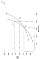
図1Aは、異なる熱条件のもとで動作する例示的な処理構成要素の1対の性能曲線(コア85℃、コア50℃)を示すグラフ300である。処理構成要素は、ヘテロジニアスマルチコアプロセッサ内のコアであってよく、効率の高いコア、効率が中程度のコア、または効率の低いコアであり得る。より具体的には、当業者であれば認めるように、処理構成要素は、限定はしないが、CPU、GPU、DSP、プログラマブルアレイ、ビデオエンコーダ/デコーダ、システムバス、カメラサブシステム(画像プロセッサ)、MDPなどを含む、所与のコードブロックを処理する能力を有する任意の処理エンジンであり得る。その上、上述のように、例示的な処理エンジンは、CPU、GPUなどの中にあるコアまたはサブコアであり得る。特に、エネルギー効率は、特定の電力消費レベルでの処理構成要素の処理性能または速度を示すために定義され得る。たとえば、エネルギー効率は、MIPS/mW(mW電力消費当たりの100万命令毎秒)またはMHz/mW(mW電力消費当たりのメガヘルツ動作クロック周波数)によって表され得る。
FIG. 1A is a
図1Aの図示からわかるように、3500MIPSの作業負荷において、50℃の環境内で動作する例示的なコアは約620mWの電力(点315)を消費するが、同じ3500MIPSの作業負荷において、動作環境が85℃に達するとき、コアの電力消費はほぼ1000mWの電力(点310)に増加する。したがって、85℃で動作するときの3.5MIPS/mWとは対照的に、約5.6MIPS/mWを処理することができるので、50℃の温度で動作するとき、例示的な処理構成要素の効率はより良い。さらに、所与の動作温度では、コアの処理効率は、作業負荷の増加につれて低減する。コア50℃の曲線を参照すると、たとえば、作業負荷が3500MIPSから約4300MIPSに増加するとき、電力消費はほぼ1000mW(点305)に増加する。 As can be seen from the illustration in FIG. 1A, at a 3500 MIPS workload, an exemplary core operating in a 50 ° C. environment consumes approximately 620 mW of power (point 315), but at the same 3500 MIPS workload, When the temperature reaches 85 ° C, the core power consumption increases to nearly 1000mW of power (point 310). Thus, as opposed to 3.5 MIPS / mW when operating at 85 ° C, approximately 5.6 MIPS / mW can be processed, so when operating at a temperature of 50 ° C, the efficiency of an exemplary processing component is Better. Furthermore, at a given operating temperature, the processing efficiency of the core decreases with increasing workload. Referring to the core 50 ° C. curve, for example, when the workload increases from 3500 MIPS to about 4300 MIPS, the power consumption increases to approximately 1000 mW (point 305).
所与の処理構成要素では、動作温度が上昇するにつれて、電力消費に関する処理構成要素の効率が低下する(すなわち、処理構成要素の動作温度が上がるにつれて、処理構成要素が所与の動作周波数において処理する能力を有するMIPSの数が減少する)ことが、図1Aの図示からわかる。特に、例示的な処理構成要素の動作温度の上昇は、限定はしないが、より高いクロック速度に関連付けられた処理構成要素内の電力漏洩の増加、処理構成要素に隣接した熱アグレッサ、処理構成要素に隣接した誤動作構成要素、周囲環境の変化などを含む、任意の数のファクタまたはファクタの組合せによって引き起こされ得ることは、当業者には認識されよう。その上、処理構成要素上の作業負荷が増加すると、電力消費の増加に関連付けられた電力漏洩率の上昇により、作業負荷配分時に処理構成要素に関連付けられた動作温度を上昇させ得ることは、当業者には認識されよう。処理構成要素の動作温度が上昇または下降し得る理由に関係なく、一般に、所与の処理構成要素の処理効率は、動作温度の上昇に反比例して下がるということを、図1Aの図示から気付くことが重要である。 For a given processing component, as the operating temperature increases, the efficiency of the processing component with respect to power consumption decreases (i.e., as the operating temperature of the processing component increases, the processing component processes at a given operating frequency). It can be seen from the illustration in FIG. 1A that the number of MIPS with the ability to In particular, the increase in operating temperature of an exemplary processing component includes, but is not limited to, increased power leakage within the processing component associated with higher clock speeds, thermal aggressor adjacent to the processing component, processing component Those skilled in the art will recognize that this can be caused by any number of factors or combinations of factors, including malfunctioning components adjacent to the environment, changes in the surrounding environment, and the like. In addition, as the workload on the processing component increases, it is possible to increase the operating temperature associated with the processing component at the time of workload distribution due to the increased power leakage rate associated with increased power consumption. It will be recognized by the contractor. It is noted from the illustration in FIG. 1A that, in general, the processing efficiency of a given processing component decreases inversely with the increase in operating temperature, regardless of why the operating temperature of the processing component may increase or decrease. is important.
ここで図1Bを見ると、異なる熱条件のもとで動作する、「低性能」CPU処理構成要素および「高性能」GPU処理構成要素という2つの例示的な処理構成要素の各々に対する、性能曲線のペア(GPU105℃、GPU95℃、CPU105℃、CPU95℃)を示すグラフ400が示されている。基本的に、図1Bのグラフ400は、2つの異なる例示的な処理構成要素の性能曲線を示し、これらの各々は、図1Aの図示によって表され得る。その上、図2の性能曲線のペアによって表される2つの例示的なプロセッサGPU、CPUは、共通のヘテロジニアスマルチプロセッサシステムオンチップ(「SoC」)内に含まれ得ることを、当業者は認識するだろう。
Turning now to FIG. 1B, performance curves for each of two exemplary processing components, a “low performance” CPU processing component and a “high performance” GPU processing component, operating under different thermal conditions. A
特に、例示的なエンジンGPU、CPUの性能曲線を重畳することによって、様々な移行点または乗換点405、410、415が、様々な曲線の交差点において定義されることが理解され得る。これらの乗換点は、異なるエンジンが最も効率的であるしきい値を表す。
In particular, it can be seen that various transition points or transfer
たとえば、例示的なGPU、CPUプロセッサの性能曲線の比較分析によって、プロセッサGPU、CPUの各々が95℃で動作している場合、約3700DMIPS(点410)の作業負荷では両方のプロセッサGPU、CPUが処理効率に関して実質的に同等であると、判定することができる。しかしながら、点410より下ではCPU処理構成要素がより効率的であること、すなわち、作業負荷が3700DMIPS未満ならば作業負荷のDMIPS当たりの電力消費はCPU処理構成要素の方が少ないことも、比較分析から理解され得る。逆に、点410より上ではGPUコアがより効率的であり、すなわち、作業負荷が3700DMIPSを超えれば作業負荷のDMIPS当たりの電力消費はGPUコアの方が少ない。 For example, according to a comparative analysis of the performance curves of exemplary GPU and CPU processors, if each of the processor GPUs and CPUs is operating at 95 degrees Celsius, both processor GPUs and CPUs will have a workload of approximately 3700 DMIPS (point 410). It can be determined that the processing efficiency is substantially equivalent. However, comparative analysis also shows that the CPU processing component is more efficient below point 410, that is, if the workload is less than 3700 DMIPS, the power consumption per DMIPS of the workload is less for the CPU processing component. Can be understood from Conversely, the GPU core is more efficient above point 410, that is, if the workload exceeds 3700 DMIPS, the GPU core consumes less power per DMIPS.
したがって、CPUが105℃で稼働しており、GPUがより低い95℃で稼働しているときの例示的な比較分析に依存すると、全熱エネルギー生成を低減するためのトリガに応答してエネルギー効率認識型熱管理ポリシーを適用する効率マネージャモジュールは、CPUの温度が高い場合であっても、ポイント405未満の作業負荷についてのあまり効率的でないGPUへの電力の低減を命令し得る。
Therefore, energy efficiency in response to a trigger to reduce total thermal energy generation, depending on an exemplary comparative analysis when the CPU is operating at 105 ° C and the GPU is operating at a lower 95 ° C An efficiency manager module that applies a cognitive thermal management policy may command a reduction in power to a less efficient GPU for workloads below
その上、いくつもの要因により、ヘテロジニアスマルチプロセッサSoC中の異なるプロセッサおよび/またはコアは、異なる熱条件で動作し得ることが理解されるだろう。たとえば、図1Bの図示では、移行点405は、105℃で動作する例示的なCPU処理構成要素の性能曲線と、95℃で動作する例示的なGPU処理構成要素の性能曲線の交差点を表す。その結果、例示的なプロセッサが異なる温度で動作していることを認識することによって、実施形態は、比較分析を利用して、上で説明された例示的な状況と同様に、処理の準備ができた所与のコードブロックを効率的に処理するために作業負荷を配分する直前に、プロセッサのうちのいずれが最も良い状態にあるかを判定することができる。たとえば、最も効率的な条件で作業負荷が処理されることを確実にするために、2400DMIPS未満の作業負荷はCPU処理構成要素に割り当てられてよく、2400DMIPSを超える作業負荷はGPU処理構成要素に割り当てられてよい。さらに、エネルギー効率認識型熱管理ソリューションの実施形態は、集合的な処理エンジンの全平均効率が最適化されるように、処理構成要素の中、およびその間に作業負荷を再配分し得ることが想定される。そうする際に、いくつかの実施形態は、単にエネルギー効率がより低いコア上で作業負荷が稼働するのを防止しようとするのではない可能性がある。すなわち、いくつかの実施形態では、作業負荷が開始すると、システムは、各構成要素のエネルギー効率を考慮し、作業負荷を、作業負荷が適合する最も効率的なCPUに配置し得る。たとえば、最も効率的なコアがすでに非常に激しく利用されている場合、次に最も効率的なコアが選択され得る。
Moreover, it will be appreciated that due to a number of factors, different processors and / or cores in a heterogeneous multiprocessor SoC can operate at different thermal conditions. For example, in the illustration of FIG. 1B,
特に、エネルギー効率認識型熱管理アルゴリズムのいくつかの実施形態は、次のコードブロックが割り当てられた場合、全作業負荷処理効率を最適化するために実行され得ることが想定される。たとえば、図1Bの図示の例示的な曲線GPU95℃およびCPU105℃を再び参照し、曲線に関連するプロセッサGPU、CPUが現在、2000DMIPSの割合で処理しており、効率管理モジュールが、2つの例示的なプロセッサのうちのいずれが、追加の作業負荷1000DMIPSを効率的に処理するのに最も良い状況にあるかを判定しようとしていると仮定する。エネルギー効率認識型熱管理アルゴリズムを使用して、現在処理されている2000DMIPSの作業負荷ではなく、処理構成要素GPU、CPUにつき想定される総作業負荷3000MIPS(エンジンごとに以前に配分された2000MIPSとエンジンのうちの1つに配分される追加の1000MIPSとの和)に基づいて、曲線を比較することができる。この非限定的な例では、図2の図示の例示的な曲線GPU95℃およびCPU105℃に基づいて、熱認識スケジューリングモジュールは、3000DMIPSで500mW超の電力を消費することになるCPUではなく、同じ作業負荷で処理するために400mW未満の電力を消費することになるより効率的なGPUを選択することができる。 In particular, it is envisioned that some embodiments of energy efficiency aware thermal management algorithms may be executed to optimize overall workload processing efficiency when the next code block is assigned. For example, referring again to the example curves GPU95 ° C and CPU105 ° C shown in Figure 1B, the processor GPU, CPU associated with the curve is currently processing at a rate of 2000 DMIPS, and the efficiency management module is Suppose that one of the active processors is trying to determine the best situation to efficiently handle the additional workload 1000DMIPS. Using an energy efficiency aware thermal management algorithm, the total workload 3000MIPS assumed per processing component GPU, CPU, rather than the currently processed 2000DMIPS workload (2000MIPS and engines previously allocated per engine) The curves can be compared based on the sum of the additional 1000 MIPS allocated to one of them. In this non-limiting example, based on the illustrated example curves GPU95 ° C and CPU105 ° C in Figure 2, the thermal recognition scheduling module does the same work, not a CPU that will consume more than 500mW at 3000DMIPS A more efficient GPU can be selected that will consume less than 400mW to process with the load.
上記の例を拡張して、追加の1000DMIPSをGPUに割り当てた後、効率管理モジュールは、CPU上で稼働する作業負荷の2000DMIPSをGPUに再配分するために移動することができ、それによって、3000DMIPSから5000DMIPSへのGPUの作業負荷がさらに増える。有利には、5000DMIPSで、GPUは、その2000DMIPSの作業負荷が再配分されなかった場合、CPUが消費するおおよそ8mW/DMIPSとは対照的に、作業負荷を処理するために、1000mWの電力または5mW/DMIPSを消費する。さらに、この例においてCPUから作業負荷が完全に取り除かれた状態で、効率マネージャモジュールは、CPUを保持状態、またはさらには電力縮小状態(power collapsed state)に移行し得、それによって、さらにエネルギーが節約され、熱エネルギー生成が軽減される。 After extending the above example and assigning an additional 1000DMIPS to the GPU, the efficiency management module can be moved to redistribute the 2000DMIPS of the workload running on the CPU to the GPU, thereby 3000DMIPS GPU workload from 1 to 5000 DMIPS further increases. Advantageously, at 5000 DMIPS, the GPU will have 1000mW power or 5mW to handle the workload, as opposed to roughly 8mW / DMIPS that the CPU consumes if its 2000DMIPS workload is not redistributed. Consumes / DMIPS. In addition, with the workload completely removed from the CPU in this example, the efficiency manager module can transition the CPU into a holding state, or even into a power collapsed state, thereby further energy savings. It is saved and heat energy generation is reduced.
エネルギー効率認識型熱管理アルゴリズムのさらに他の実施形態を使用して、追加の作業負荷が割り当てられた場合に予測される曲線のシフトに基づいて性能曲線を比較することができる。たとえば、それぞれ95℃および105℃の動作温度でそれぞれ2000DMIPSの割合で処理しているプロセッサGPUおよびCPUの例を再び参照すると、効率管理モジュールの実施形態は、追加の1000DMIPSの作業負荷配分から生じ得る性能曲線のシフトを予測することができる。特に、追加の1000DMIPSの作業負荷により、それが割り当てられた処理構成要素がより多くの電力を消費することがあるので、効率管理モジュールは、処理構成要素に現在関連付する動作温度が、追加の作業負荷により上昇すると考え、それにより、予測される温度上昇に関連する性能曲線を比較しようとすることがある。 Still other embodiments of energy efficiency aware thermal management algorithms can be used to compare performance curves based on the expected curve shifts when additional workload is allocated. For example, referring again to the example processor GPU and CPU processing at a rate of 2000 DMIPS, respectively at operating temperatures of 95 ° C. and 105 ° C., respectively, efficiency management module embodiments may result from an additional 1000 DMIPS workload distribution Performance curve shifts can be predicted. In particular, because of the additional 1000 DMIPS workload, the processing component to which it is assigned may consume more power, so the efficiency management module will allow the operating temperature currently associated with the processing component to We may think that it will increase due to workload and thereby try to compare the performance curves associated with the expected temperature increase.
例に戻ると、追加の作業負荷1000DMIPSにより、GPUの動作温度は95℃から100℃に上昇し、同様に、CPUの動作温度は105℃から110℃に上昇し得る。したがって、効率管理モジュールの実施形態は、それぞれ予測される温度100℃および110℃で動作するコアGPUおよびコアCPUに関連付けられる性能データ(図1Bには示されていないGPU100℃およびCPU110℃の性能曲線)を照会し、比較することができる。
Returning to the example, with an additional workload of 1000 DMIPS, the GPU operating temperature can be increased from 95 ° C. to 100 ° C., as well as the CPU operating temperature can be increased from 105 ° C. to 110 ° C. Thus, the efficiency management module embodiment provides performance data associated with core GPUs and core CPUs operating at expected temperatures of 100 ° C. and 110 ° C., respectively (
図1Cは、例示的な1対のコア、コア1およびコア2についての1対の性能曲線を示すグラフ500である。「遅い」コアと見なされ得るコア1に対して、コア2は、「速い」コアと見なされ得る。特に、当業者は、コア2は、コア1(約2100MHz)よりも高い最大周波数(約2500MHz)で処理することができるので、コア2を例示的な対のうちの速いコアとして認識する。したがって、および動作周波数がMIPSと相関するので、当業者は、コア2がコア1よりも多くMIPSを処理することができることも認識する。
FIG. 1C is a
図1Cの図における点510は、コア2がコア1よりも1MIPSの作業負荷を処理することにおいてより効率的である周波数(およそ1600MHz)を表す[2000MHzで、コア2は、およそ800mWの電力を消費しているだけである(点515)のに対して、コア1は、同じ2000MHzの動作周波数でおよそ1100mWの電力を消費している(点520)]。しかしながら、特に、点510より下では、例示的なコア1は、2つのうちより効率的なプロセッサである。したがって、コア1とコア2の両方が1600MHz未満の周波数で稼働しており、効率管理モジュールが熱エネルギー生成を低減するためのトリガ(たとえば、皮膚温しきい値を超えることに対する熱警報など)を認識した場合、効率管理モジュールは、トリガ時にコア2がコア1よりも「熱かった」かどうかにかかわらず、コア2に供給される周波数を低減しようとし得る。このようにして、所与のMIPSの作業負荷を処理する全効率が最適化されるとともに、熱エネルギー生成が軽減され得る。
図1Dは、図1Cの図において示した、例示的な1対のコア、コア1およびコア2についての異なる1対の性能曲線を示すグラフ600である。図1Dにおいて、性能曲線の各々は、コアのエネルギー効率対コアに供給される周波数をマッピングする。特に、図1Dの図における点610および615は、それぞれ、図1Cの図における点510および515/520と相関する。同様に、図1Dの図に示される最大動作周波数は、図1Cの図に示される最大動作周波数と相関する。
FIG. 1D is a
図1Dの図によって表される性能データを使用して、エネルギー効率認識型熱管理ソリューションの一実施形態は、両方のコアがそれらの最大動作周波数で、またはその近くで稼働している場合、最初にコア1に供給される周波数を低減することによって、熱トリガに反応し得る。特に、2000MHzの最大動作周波数で、コア1は、コア2よりも消費される電力のmW当たりより少ないMIPSの作業負荷を処理している。したがって、例示的なエネルギー効率認識型熱管理ソリューションは、熱エネルギー生成を軽減し、熱警報を解除しようとして、ワンステップで、コア1の周波数を低減し得る。あまり効率的でないコア1の周波数の低減が警報を解除しない場合、例示的なエネルギー効率認識型熱管理ソリューションは、第1のステップの低減後、コアのうちのどれがあまり効率的でないかを再評価し、周波数の第2のステップの低減を、エネルギー効率が最も低いコアに適用し得る。このプロセスは、そのようなステップバイステップ方式で、熱警報が解除されるまで、または、そうでなければ、熱軽減目標が達成されるまで、ステップの低減時に、エネルギー効率が最も低いコアに供給される周波数を低減し続ける。
Using the performance data represented by the diagram in FIG. 1D, one embodiment of an energy efficiency-aware thermal management solution is the first when both cores are operating at or near their maximum operating frequency. By reducing the frequency supplied to the
図2Aは、ヘテロジニアス処理構成要素を含むオンチップシステム102Aにおける非同期のアーキテクチャの態様を示す機能ブロック図である。エネルギー効率認識型熱管理ソリューションのいくつかの実施形態は、作業負荷処理効率を不必要に下げることなく、処理構成要素による熱エネルギー生成を管理することに適用可能であり得る。
FIG. 2A is a functional block diagram illustrating aspects of an asynchronous architecture in an on-
オンチップシステム102Aは、一連の処理構成要素PC0、PC1、PC2などを示すために表される。特に、オンチップシステム102Aのアーキテクチャは非同期であるので、処理構成要素の各々は、電源電圧およびクロックジェネレータ周波数、たとえば当業者によって理解されるように、位相ロックループ(「PLL」)などを制御するための専用クロックソースに関連付けられ得る。図において、クロック0は、PC0に対する電源およびクロックジェネレータに一意に関連付けられている。クロック1は、PC1に対する電源およびクロックジェネレータに一意に関連付けられている。クロック2は、PC2に対する電源およびクロックジェネレータに一意に関連付けられており、以下同様である。
The on-
有利には、非同期オンチップシステムにおける各処理構成要素が専用のクロックソースを有するので、エネルギー効率認識型熱管理ソリューションの実施形態は、熱エネルギー生成がしきい値を超えると、エネルギー効率が最も低い処理構成要素における目標とされた電力の低減を行うために、DCVSモジュールを使用し得る。 Advantageously, each processing component in an asynchronous on-chip system has a dedicated clock source so that an embodiment of an energy efficiency aware thermal management solution is least energy efficient when thermal energy generation exceeds a threshold A DCVS module may be used to achieve targeted power reduction in the processing component.
図2Bは、ヘテロジニアス処理構成要素を含むオンチップシステム102Bにおける同期のアーキテクチャの態様を示す機能ブロック図である。エネルギー効率認識型熱管理ソリューションのいくつかの実施形態は、作業負荷処理効率を不必要に下げることなく、処理構成要素による熱エネルギー生成を管理することに適用可能であり得る。
FIG. 2B is a functional block diagram illustrating aspects of a synchronization architecture in an on-
オンチップシステム102Bは、一連の処理構成要素PC0、PC1、PC2などを示すために表される。特に、オンチップシステム102Bのアーキテクチャが同期しているので、処理構成要素の各々は、すべての処理構成要素に対する単一の共通のクロックソースおよび電源に関連付けられる。有利には、同期のオンチップシステムにおける各処理構成要素が単一のクロックソースを共有するので、エネルギー効率認識型熱管理ソリューションの実施形態は、あまり効率的でない処理構成要素からより効率的な処理構成要素に作業負荷を配分または再配分することによって、熱エネルギー生成がしきい値を超えたとき、処理効率を最適化し得る。
On-
特に、あまり効率的でない処理構成要素は作業負荷がないので、エネルギー効率認識型熱管理ソリューションの実施形態は、あまり効率的でない処理構成要素の電力状態が、たとえば、アクティブ状態から保持状態に移行する、または保持状態から電力縮小状態に移行するよう命令し得る。有利には、新たな作業負荷をより効率的なプロセッサに配分する、および/またはアクティブな作業負荷をあまり効率的でないプロセッサからより効率的なプロセッサに再配分することによって、本ソリューションの実施形態は、所与の作業負荷を処理するために必要な電力量を最適化し得る。さらに、より効率的な処理構成要素が許容できるQoSを維持することができない場合、あまり効率的でない処理構成要素をオンラインに戻すためのレイテンシパラメータに鑑みて、同期のSoC102Bにおけるあまり効率的でない処理構成要素をアクティブ状態からアイドル状態に移行することによって、エネルギー効率認識型熱管理ソリューションの実施形態は、全電力消費効率をさらに最適化することができる。
In particular, because less efficient processing components have no workload, an embodiment of an energy efficiency aware thermal management solution causes the power state of less efficient processing components to transition from an active state to a hold state, for example Or may be instructed to transition from a hold state to a reduced power state. Advantageously, embodiments of the solution allow for the distribution of new workloads to more efficient processors and / or redistributing active workloads from less efficient processors to more efficient processors. , One can optimize the amount of power required to handle a given workload. In addition, if a more efficient processing component is unable to maintain acceptable QoS, the less efficient processing configuration in the
図3は、ポータブルコンピューティングデバイス(「PCD」)100におけるエネルギー効率認識型熱管理のためのオンチップシステム102の一実施形態を示す機能ブロック図である。特に、オンチップシステム102がアーキテクチャにおいて同期または非同期であり得ることが想定される。図1の図に対して上で説明されたように、電源電圧およびクロックジェネレータ周波数の目標とされた低減、ならびに/または処理構成要素にわたる作業負荷の配分は、個々のコアまたはプロセッサ222、224、226、228に一意に関連付けられた性能データの比較分析に基づき得る。特に、当業者は、処理構成要素110が説明のためにのみヘテロジニアス処理エンジンのグループとして示されており、各々が複数のコアおよび/またはサブコアを含むことも含まないこともある複数のヘテロジニアスコア222、224、226、228または複数のヘテロジニアスプロセッサ222、224、226、228を有する単一の処理構成要素を表し得ることを認識するだろう。したがって、処理エンジン222、224、226および228を本明細書において「コア」と呼ぶことは、本質的に例示的なものと理解され、本開示の範囲を限定しない。
FIG. 3 is a functional block diagram illustrating one embodiment of an on-
オンチップシステム102は、効率マネージャ(「EM」)モジュール101、DCVSモジュール26、およびスケジューラモジュール207と通信しているモニタモジュール114を用いて、コア222、224、226、228に個々に関連付けられている温度センサ157を監視し得る。モニタモジュール114は、限定的はしないが、皮膚温センサ、PoPメモリ温度センサ、接合温度センサ、処理構成要素に対する電力レール上の電流センサ、電源に関連した電流センサ、電源能力センサなど、しきい値を超え得る任意の数の熱エネルギーインジケータを監視することもできる。
On-
熱しきい値を超え、それがモニタモジュール114によって認識された場合、EMモジュール101は、エネルギー効率認識型の方法で熱エネルギー生成を軽減するための対策を講じるためにトリガされ得る。EMモジュール101は、モニタモジュール114から、処理構成要素のエネルギー効率に関連付けられた1つまたは複数の監視されたパラメータの表示を受信し、次いで、それらの表示を使用して、処理構成要素のうちのどれがエネルギー効率が最も低いかを判断し得る。いくつかの実施形態では、EMモジュール101は、モニタモジュール114から温度測定値を受信し、測定値を使用して、コア性能データストア24に性能データについて問い合わせ得る。性能データに基づいて、EMモジュール101は、作業負荷処理効率によってコア222、224、226、228のランキングを決定し得る。
If the thermal threshold is exceeded and it is recognized by the
その後、EMモジュール101は、非同期システム102Aにおけるあまり効率的でないコアに対する電源電圧およびクロックジェネレータ周波数を低減することを決定することができ、または同期システム102Bにおいて、EMモジュール101は、作業負荷があまり効率的でないコアからより効率的なコアに再配分されるようにし得る、または、待ち行列に入れられた作業負荷がより効率的なコアにスケジュールされるようにし得る。EMモジュール101によって命令された動的なDCVS調整ポリシーは、あまり効率的でない処理構成要素において低減されたレベルでプロセッサクロック速度を設定する、いくつかのあまり効率的でないプロセッサの電力状態をアクティブ状態からアイドル状態に移行するなどを行い得る。いくつかの実施形態では、EMモジュール101によって命令された作業負荷の配分および/または再配分は、スケジューラ207に対する命令を介して実施され得る。特に、エネルギー効率認識型熱管理ポリシーの適用を通して、EMモジュール101は、QoSを犠牲にして過度な電力消費を低減または緩和し得る。
The
当業者には認識されるように、処理コア222、224、226、228のうちの1つまたは複数の動作温度は、作業負荷が処理されるとき、周囲条件が変化するとき、隣接した熱エネルギー発生器がエネルギーを散逸させるときなどに変動することがある。したがって、様々な処理コア222、224、226、228の動作温度が変動するとき、それらのエンジン222、224、226、228に関連付けられた関連する性能データも変動する。コア222、224、226、228の各々に関連付けられた動作温度が変化するとき、モニタモジュール114は変化を認識し、変化を示す温度データをEMモジュール101へ送信し得る。測定された動作温度の変化は、EMモジュール101が、測定された動作温度に基づいてコア222、224、226、228のうちの1つまたは複数のための性能曲線について問い合わせるために、コア性能(「CP」)データストア24を参照することをトリガし得る。その後、EMモジュール101は、異なるコア222、224、226、228をエネルギー効率が最も低いコアと識別し、消費された電力のミリワット当たりの作業負荷のより効率的な処理を維持しながら、生成された熱エネルギーが軽減されるように、(DCVSモジュール26を介して)それに供給される電力周波数を調整し得る。EMモジュール101はまた、識別された性能曲線を比較し、待ち行列に入れられたコードブロック、またはあまり効率的でないコアからの再配分を必要とするコードブロックを効率的に処理するために比較時に最良に配置されたコア222、224、226、228を選択し得る。
As will be appreciated by those skilled in the art, the operating temperature of one or more of the
例示的なEMモジュール101は、様々な多様な処理構成要素222、224、226、228に関連付けられた1つまたは複数の性能曲線の比較分析を活用して、電力供給を調整するように、DCVSモジュール26に命令する、および/または作業負荷を効率的に処理するために最良に配置されたある処理構成要素に作業負荷を配分するもしくは再配分するように、スケジューラモジュール207に命令するように構成される。特に、当業者は、処理構成要素222、224、226、228の動作温度が変化したときには、EMモジュール101によって照会され、比較される性能曲線も変化することを認識するだろう。したがって、異なる時間にEMモジュール101は、エネルギー効率認識型熱管理ポリシーの適用のために異なる処理エンジン222、224、226、228を選択することができる。このようにして、配分時に利用可能な最も効率的な処理構成要素に作業負荷の割当てが配分されることを確実にすることによって、および/またはより効率的なプロセッサがアクティブな作業負荷を処理できるようにするために、エネルギー効率が最も低い処理構成要素による電力消費が低減されることを確実にすることによって、熱エネルギー生成を管理するとき、EMモジュール101がQoSを最適化することは、いくつかの実施形態の利点である。
The
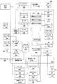
図4は、熱条件を監視し、性能データを比較し、最適電力周波数を設定し、効率的に処理するために最良に配置された処理構成要素に作業負荷をスケジュールするための方法およびシステムを実装するための、ワイヤレス電話の形態のPCD100の例示的で非限定的な態様の機能ブロック図である。図示されるように、PCD100は、互いに結合されたヘテロジニアスマルチコア中央処理装置(「CPU」)110およびアナログ信号プロセッサ126を含む、オンチップシステム102を含む。当業者によって理解されるように、CPU110は、0番目のコア222、1番目のコア224、およびN番目のコア230を備えてもよい。さらに、当業者によって理解されるように、CPU110の代わりに、デジタル信号プロセッサ(「DSP」)も利用され得る。その上、ヘテロジニアスマルチコアプロセッサの技術分野で理解されるように、コア222、224、230の各々は、同様の動作条件のもとで異なる効率で作業負荷を処理し得る。
Figure 4 shows a method and system for monitoring thermal conditions, comparing performance data, setting optimal power frequencies, and scheduling workloads to the best placed processing components for efficient processing. FIG. 2 is a functional block diagram of an exemplary, non-limiting aspect of a
一般に、効率マネージャモジュール101は、モニタモジュール114から温度データを受信し、温度データを使用してコア222、224、230に関連付けられた性能データについて問い合わせる、または性能データを推定し、コア222、224、230の相対的な処理効率を決定し、DCVSモジュール26および/またはスケジューラ207とともに働いて、電源を調整し、電力状態を移行し、および/またはコア222、224、230に対するコードブロックをスケジュールすることができる。
In general, the
モニタモジュール114は、オンチップシステム102全体を通して分散された複数の動作するセンサ(たとえば、熱センサ157)、およびPCD100のCPU110、ならびにEMモジュール101と通信する。EMモジュール101は、モニタモジュール114とともに働いて、モニタモジュール114によって監視された温度に関係するプロセッサ性能曲線について問い合わせ、曲線を比較し、電力周波数を最も効率的なレベルに設定し、コードブロックを処理する能力を有する利用可能な最も効率的なプロセッサを選択し得る。
The
図4に示すように、ディスプレイコントローラ128およびタッチスクリーンコントローラ130は、デジタル信号プロセッサ110に結合される。オンチップシステム102の外部にあるタッチスクリーンディスプレイ132は、ディスプレイコントローラ128およびタッチスクリーンコントローラ130に結合される。
As shown in FIG. 4, display controller 128 and touch screen controller 130 are coupled to
PCD100は、ビデオデコーダ134、たとえば位相反転線(「PAL」)デコーダ、順次式カラーメモリ(「SECAM」)デコーダ、全国テレビジョン方式委員会(「NTSC」)デコーダ、または任意の他のタイプのビデオデコーダ134をさらに含み得る。ビデオデコーダ134は、マルチコア中央処理ユニット(「CPU」)110に結合される。ビデオ増幅器136は、ビデオデコーダ134およびタッチスクリーンディスプレイ132に結合される。ビデオポート138は、ビデオ増幅器136に結合される。図4に示されるように、ユニバーサルシリアルバス(「USB」)コントローラ140が、CPU110に結合される。同様に、USBポート142は、USBコントローラ140に結合される。メモリ112および加入者識別モジュール(SIM)カード146も、CPU110に結合されてもよい。さらに、図4に示すように、デジタルカメラ148が、CPU110に結合され得る。例示的な態様では、デジタルカメラ148は、電荷結合デバイス(「CCD」)カメラまたは相補型金属酸化膜半導体(「CMOS」)カメラである。
The
図4にさらに示されるように、ステレオオーディオコーデック150が、アナログ信号プロセッサ126に結合される場合がある。さらに、オーディオ増幅器152が、ステレオオーディオコーデック150に結合される場合がある。例示的な態様では、第1のステレオスピーカ154および第2のステレオスピーカ156が、オーディオ増幅器152に結合される。図4は、マイクロフォン増幅器158もステレオオーディオコーデック150に結合される場合があることを示す。さらに、マイクロフォン160が、マイクロフォン増幅器158に結合される場合がある。特定の態様では、周波数変調(FM)ラジオチューナ162が、ステレオオーディオコーデック150に結合される場合がある。同様に、FMアンテナ164が、FMラジオチューナ162に結合される。さらに、ステレオヘッドフォン166が、ステレオオーディオコーデック150に結合されてもよい。
As further shown in FIG. 4, a
図4は、無線周波数(RF)トランシーバ168がアナログ信号プロセッサ126に結合され得ることをさらに示している。RFスイッチ170が、RFトランシーバ168およびRFアンテナ172に結合されてもよい。図4に示されるように、キーパッド174が、アナログ信号プロセッサ126に結合される場合がある。また、マイクロフォン付きモノヘッドセット176が、アナログ信号プロセッサ126に結合される場合がある。さらに、バイブレータデバイス178が、アナログ信号プロセッサ126に結合される場合がある。図4は、たとえばバッテリなどの電源180がオンチップシステム102に結合されることも示す。特定の態様では、電源は、充電式DCバッテリ、または交流(「AC」)電源に接続されたAC-DC変換器から導出されるDC電源を含む。
FIG. 4 further illustrates that a radio frequency (RF) transceiver 168 may be coupled to the analog signal processor 126. An
CPU110は、1つまたは複数の内部のオンチップ熱センサ157A、ならびに、1つまたは複数の外部のオフチップ熱センサ157Bにも結合され得る。オンチップ熱センサ157Aは、縦型PNP構造に基づき、通常は相補型金属酸化膜半導体(「CMOS」)の超大規模集積(「VLSI」)回路に専用の、1つまたは複数の絶対温度比例(「PTAT」)の温度センサを備え得る。オフチップ熱センサ157Bは、1つまたは複数のサーミスタを含み得る。熱センサ157は、アナログデジタル変換器(「ADC」)コントローラ103を用いてデジタル信号に変換される、電圧降下を生じさせ得る。しかしながら、本発明の範囲から逸脱することなく、他のタイプの熱センサ157が採用され得る。
熱センサ157は、ADCコントローラ103によって制御され監視されることに加えて、1つまたは複数のEMモジュール101によっても制御され監視され得る。EMモジュール101は、CPU110によって実行されるソフトウェアを含み得る。しかしながら、本発明の範囲から逸脱することなく、EMモジュール101はまた、ハードウェアおよび/またはファームウェアから形成され得る。EMモジュール101は、プロセッサ性能データについて問い合わせ、および/またはプロセッサ性能の表示を受信し、データの分析に基づいて、エネルギー効率が最も低いプロセッサの電力周波数を調整し、および/またはコードブロックを、作業負荷配分時にコードを効率的に処理する能力が最も高いプロセッサに配分するもしくは再配分することを担い得る。
In addition to being controlled and monitored by the
図4に戻ると、タッチスクリーンディスプレイ132、ビデオポート138、USBポート142、カメラ148、第1のステレオスピーカ154、第2のステレオスピーカ156、マイクロフォン160、FMアンテナ164、ステレオヘッドフォン166、RFスイッチ170、RFアンテナ172、キーパッド174、モノヘッドセット176、バイブレータ178、熱センサ157B、および電源180は、オンチップシステム102の外部にある。しかしながら、モニタモジュール114はまた、PCD100において動作可能なリソースのリアルタイム管理を助けるために、これらの外部のデバイスのうちの1つまたは複数から、アナログ信号プロセッサ126およびCPU110によって1つまたは複数の指示または信号を受信できることを理解されたい。
Returning to FIG. 4, touch screen display 132, video port 138,
特定の態様では、本明細書で説明する方法ステップのうちの1つまたは複数は、1つまたは複数のEMモジュール101を形成する、メモリ112に記憶された実行可能命令およびパラメータによって実施され得る。EMモジュール101を形成するこれらの命令は、本明細書で説明する方法を実施するために、ADCコントローラ103に加えて、CPU110、アナログ信号プロセッサ126、または別のプロセッサによって実行され得る。さらに、プロセッサ、110、126、メモリ112、そこに記憶された命令、またはそれらの組合せは、本明細書で説明される方法ステップのうちの1つまたは複数を実行するための手段として働く場合がある。
In certain aspects, one or more of the method steps described herein may be performed by executable instructions and parameters stored in
図5Aは、図4に示されるチップ102のための、ハードウェアの例示的な空間構成を示す機能ブロック図である。この例示的な実施形態によれば、アプリケーションCPU110は、チップ102の遠く左側の領域に配置されるが、モデムCPU168、126は、チップ102の遠く右側の領域に配置される。アプリケーションCPU110は、第0のコア222、第1のコア224、および第Nのコア230を含む、ヘテロジニアスマルチコアプロセッサを含み得る。アプリケーションCPU110は、EMモジュール101Aを実行していてよく(ソフトウェアで具現化される場合)、または、EMモジュール101Aを含んでよい(ハードウェアで具現化される場合)。アプリケーションCPU110は、オペレーティングシステム(「O/S」)モジュール208およびモニタモジュール114を含むように、さらに例示される。
FIG. 5A is a functional block diagram illustrating an exemplary spatial configuration of hardware for the
アプリケーションCPU110は、アプリケーションCPU110に隣接して配置されチップ102の左側の領域にある、1つまたは複数の位相ロックループ(「PLL」)209A、209Bに結合され得る。PLL209A、209Bに隣接しアプリケーションCPU110の下に、アプリケーションCPU110の主要なモジュール101Aとともに動作する固有のEMモジュール101Bを含み得るアナログデジタルコントローラ(「ADC」)103が、含まれ得る。
ADCコントローラ103のEMモジュール101Bは、モニタモジュール114とともに、「チップ102上」および「チップ102外」に設けられ得る複数の熱センサ157を監視および追跡することを担い得る。オンチップまたは内部熱センサ157Aは、様々な位置に配置され得る。
The
非限定的な例として、第1の内部熱センサ157A1は、アプリケーションCPU110とモデムCPU168、126との間に、かつ内部メモリ112に隣接して、チップ102の上部の中心領域に配置され得る。第2の内部熱センサ157A2は、モデムCPU168、126の下の、チップ102の右側領域に配置され得る。この第2の内部熱センサ157A2は、進化した縮小命令セットコンピュータ(「RISC」)命令セットマシン(「ARM」)177と第1のグラフィックプロセッサ135Aとの間にも配置され得る。デジタルアナログコントローラ(「DAC:digital-to-analog controller」)173は、第2の内部熱センサ157A2とモデムCPU168、126との間に配置され得る。
As a non-limiting example, the first internal thermal sensor 157A1 can be located in the central region at the top of the
第3の内部熱センサ157A3は、第2のグラフィックプロセッサ135Bと第3のグラフィックプロセッサ135Cとの間の、チップ102の遠く右側の領域に配置され得る。第4の内部熱センサ157A4は、チップ102の遠く右側の領域に、かつ第4のグラフィックプロセッサ135Dの下に配置され得る。第5の内部熱センサ157A5は、チップ102の遠く左側の領域に、かつPLL209およびADCコントローラ103に隣接して配置され得る。
The third internal heat sensor 157A3 may be disposed in the far right region of the
1つまたは複数の外部熱センサ157Bも、ADCコントローラ103に結合され得る。第1の外部熱センサ157B1は、チップの外部に、かつ、モデムCPU168、126、ARM177、およびDAC173を含み得るチップ102の右上4分の1の領域に隣接して配置され得る。第2の外部熱センサ157B2は、チップの外部に、かつ、第3のグラフィックプロセッサ135Cおよび第4のグラフィックプロセッサ135Dを含み得るチップ102の右下4分の1の領域に隣接して配置され得る。
One or more external thermal sensors 157B may also be coupled to the
図5Aに示されるハードウェアの様々な他の空間構成が、本発明の範囲から逸脱することなく実現され得ることを、当業者は認識するだろう。図5Aは、1つの例示的な空間配置、および主要なEMモジュール101AおよびそのEMモジュール101Bを有するADCコントローラ103が図5Aに示される例示的な空間配置に応じて決まる熱条件を認識し、処理効率データを比較し、作業負荷を配分する、またはQoSに不必要に影響を与えることなく熱条件を管理するよう電源を調整するために、モニタモジュール114とどのように連携し得るかを示す。
Those skilled in the art will recognize that various other spatial configurations of the hardware shown in FIG. 5A can be implemented without departing from the scope of the present invention. FIG. 5A recognizes and processes one exemplary spatial arrangement and thermal conditions determined by the
図5Bは、熱条件の識別およびエネルギー効率認識型熱管理アルゴリズムの適用をサポートするための、図4および図5AのPCD100の例示的なソフトウェアアーキテクチャ200を示す概略図である。任意の数のアルゴリズムが、ある熱条件が満たされる場合に、EMモジュール101によって適用され得る少なくとも1つのエネルギー効率認識型熱管理技法を形成することができ、またはその一部であり得る。
FIG. 5B is a schematic diagram illustrating an
図5Bに示されるように、CPUまたはデジタル信号プロセッサ110は、バス211を介してメモリ112に結合される。上で述べられたように、CPU110は、N個のコアプロセッサを有する複数コアのヘテロジニアスプロセッサである。すなわち、CPU110は、第1のコア222、第2のコア224、および第Nのコア230を含む。当業者には知られているように、第1のコア222、第2のコア224、および第Nのコア230の各々は、専用のアプリケーションまたはプログラムをサポートするのに利用可能であり、ヘテロジニアスプロセッサの一部として、同様の熱的な動作条件のもとで異なるレベルの性能を提供し得る。あるいは、利用可能なヘテロジニアスコアの2つ以上にわたる処理のために、1つまたは複数のアプリケーションまたはプログラムは分散していてよい。
As shown in FIG. 5B, the CPU or
CPU110は、ソフトウェアおよび/またはハードウェアを備え得るEMモジュール101から、コマンドを受信し得る。ソフトウェアとして具現化される場合、EMモジュール101は、CPU110および他のプロセッサによって実行されている他のアプリケーションプログラムにコマンドを出す、CPU110によって実行される命令を備える。
CPU110の第1のコア222、第2のコア224〜第Nのコア230は、単一の集積回路ダイに集積されるか、または、複数回路のパッケージにおいて別個のダイ上で集積または結合される場合がある。設計者は、第1のコア222、第2のコア224〜第Nのコア230を、1つまたは複数の共有キャッシュを介して結合することができ、バス、リング、メッシュ、およびクロスバートポロジーのようなネットワークトポロジーを介して、メッセージまたは命令の伝達を実施することができる。
The
当技術分野で知られているように、バス211は、1つまたは複数のワイヤード接続またはワイヤレス接続を介した複数の通信経路を含み得る。バス211は、通信を可能にするために、コントローラ、バッファ(キャッシュ)、ドライバ、リピータ、および受信機のような、簡単にするために省略される追加の要素を有してもよい。さらに、バス211は、上述の構成要素の間での適切な通信を可能にするために、アドレス、制御、および/またはデータ接続を含むことができる。
As is known in the art, the
図5Bに示すように、PCD100によって使用される論理がソフトウェアで実装されるとき、開始論理250、管理論理260、エネルギー効率認識型熱管理インターフェース論理270、アプリケーションストア280内のアプリケーション、およびファイルシステム290の部分のうちの1つまたは複数が、任意のコンピュータ関連のシステムまたは方法によって、またはそれと関連して使用するために、任意のコンピュータ可読媒体に記憶され得ることに留意されたい。
As shown in FIG. 5B, when the logic used by
本明細書の文脈では、コンピュータ可読媒体は、コンピュータ関連システムまたは方法によって、またはそれと関連して使用するために、コンピュータプログラムおよびデータを含むか、または記憶することができる、電子式、磁気式、光学式、または他の物理デバイスまたは手段である。様々な論理要素およびデータストアは、命令実行システム、装置、またはデバイスから命令を取り出し、命令を実行することができる、コンピュータベースのシステム、プロセッサを含むシステム、または他のシステムなどの、命令実行システム、装置またはデバイスによって、またはそれと関連して使用するために、任意のコンピュータ可読媒体において具現化され得る。本明細書の文脈では、「コンピュータ可読媒体」は、命令実行システム、装置、またはデバイスによって、またはそれと関連して使用するために、プログラムを記憶、通信、伝搬、または移送することができる任意の手段であり得る。 In the context of this specification, a computer-readable medium is an electronic, magnetic, which may contain or store a computer program and data for use by or in connection with a computer-related system or method. An optical or other physical device or means. Various logic elements and data stores are capable of fetching instructions from an instruction execution system, apparatus or device and executing the instructions, such as a computer-based system, a system including a processor, or other system. Can be embodied in any computer-readable medium for use by or in connection with an apparatus or device. In the context of this specification, a “computer-readable medium” is any medium that can store, communicate, propagate, or transport a program for use by or in connection with an instruction execution system, apparatus, or device. It can be a means.
コンピュータ可読媒体は、たとえば、限定はしないが、電子、磁気、光学、電磁、赤外線、または半導体のシステム、装置、デバイス、または伝搬媒体であることができる。コンピュータ可読媒体のより具体的な例(非包括的なリスト)を挙げると、以下のもの、すなわち、1つまたは複数のワイヤを有する電気的接続(電子的)、ポータブルコンピュータディスケット(磁気的)、ランダムアクセスメモリ(RAM)(電子的)、読取り専用メモリ(ROM)(電子的)、消去可能プログラマブル読取り専用メモリ(EPROM、EEPROM、またはフラッシュメモリ)(電子的)、光ファイバー(光学的)、およびポータブルコンパクトディスク読取り専用メモリ(CDROM)(光学的)を含むことになる。プログラムは、たとえば、紙または他の媒体の光学的走査を介して電子的に取り込まれ、次いでコンパイルされ、解釈され、またはさもなければ必要な場合に適当な方法で処理され、次いでコンピュータメモリに記憶され得るので、コンピュータ可読媒体が、そこにプログラムが印刷されている紙または別の適当な媒体でさえあり得ることに留意されたい。 The computer readable medium can be, for example but not limited to, an electronic, magnetic, optical, electromagnetic, infrared, or semiconductor system, apparatus, device, or propagation medium. More specific examples of computer readable media (non-comprehensive list) include: electrical connections (electronic) with one or more wires, portable computer diskettes (magnetic), Random access memory (RAM) (electronic), read-only memory (ROM) (electronic), erasable programmable read-only memory (EPROM, EEPROM, or flash memory) (electronic), optical fiber (optical), and portable It will include a compact disc read only memory (CDROM) (optical). The program is captured electronically, for example via optical scanning of paper or other media, then compiled, interpreted, or otherwise processed in an appropriate manner if necessary and then stored in computer memory It should be noted that the computer readable medium can be paper or even another suitable medium on which the program is printed.
代替の実施形態では、開始論理250、管理論理260、および場合によってはエネルギー効率認識型熱管理インターフェース論理270のうちの1つまたは複数がハードウェアに実装されるとき、様々な論理は、各々当技術分野でよく知られている以下の技術、すなわち、データ信号に対する論理機能を実装するための論理ゲートを有する個別の論理回路、適切な組合せの論理ゲートを有する特定用途向け集積回路(ASIC)、プログラマブルゲートアレイ(PGA)、フィールドプログラマブルゲートアレイ(FPGA)などのうちのいずれか、またはその組合せによって実装することができる。
In an alternative embodiment, when one or more of
メモリ112は、フラッシュメモリまたはソリッドステートメモリデバイスなどの不揮発性データ記憶デバイスである。単一のデバイスとして示されるが、メモリ112は、デジタル信号プロセッサ(または、追加のプロセッサコア)に結合される別個のデータストアとともに分散されたメモリデバイスであり得る。
The
開始論理250は、エネルギー効率認識比較分析、およびエネルギー効率認識型熱管理ポリシーの適用のために利用可能なコアのうちの1つまたは複数の識別のために、選択プログラムを選択的に特定し、ロードし、実行するための1つまたは複数の実行可能命令を含む。
管理論理260は、エネルギー効率認識型熱管理プログラムを終了し、さらに、利用可能なコアのうちの1つまたは複数に対するエネルギー効率認識比較分析、調整された電源のための選択、および/または作業負荷配分のためのより適切な交換プログラムを選択的に特定し、ロードし、実行するための1つまたは複数の実行可能命令を含む。管理論理260は、実行時に、またはPCD100が電力供給されデバイスのオペレータによって使用されている間に、これらの機能を実行するように構成される。交換プログラムは、組込みファイルシステム290のプログラムストア296において見出され得る。
The
代替プログラムは、デジタル信号プロセッサのコアプロセッサのうちの1つまたは複数よって実行されるときに、EMモジュール101およびモニタモジュール114によって提供される1つまたは複数の信号に従って動作することができる。この点について、監視モジュール114は、EMモジュール101から発せられる制御信号に応答して、イベント、プロセス、アプリケーション、リソース状態の条件、経過時間、温度などの、1つまたは複数のインジケータを提供することができる。
The alternative program can operate according to one or more signals provided by the
インターフェース論理270は、組込みファイルシステム290に記憶された情報を観察し、構成し、またはそうでなければ更新するために、外部入力を提示し、外部入力を管理し、かつ外部入力と相互にやりとりするための1つまたは複数の実行可能命令を含む。一実施形態では、インターフェース論理270は、USBポート142を介して受信された製造業者入力とともに動作することができる。これらの入力は、プログラムストア296から削除されるか、またはプログラムストア296に加えられることになる1つまたは複数のプログラムを含むことができる。代替的には、入力は、プログラムストア296内のプログラムのうちの1つまたは複数への編集または変更を含むことができる。さらに、入力は、開始論理250および管理論理260の一方または両方に対する1つまたは複数の変更、または全体的な代替を特定することができる。例として、入力は、皮膚温に関連付けられた温度測定値がある識別されたしきい値を超えると、あまり効率的でないコアからより効率的なコアに作業負荷を再配分するようPCD100に命令する管理ロジック260への変更を含み得る。さらなる例として、入力は、バッテリレベルがあるフロア量に達すると、エネルギー効率が最も低い処理コアに対する電力を1増分だけ低減するようPCD100に命令する管理ロジック260への変更を含み得る。
The
インターフェース論理270により、製造業者が、PCD100の定義された動作状態の下で、エンドユーザの体験を制御可能に構成および調整することが可能になる。メモリ112がフラッシュメモリであるとき、開始論理250、管理論理260、インターフェース論理270、アプリケーション記憶装置280内のアプリケーションプログラム、または組込みファイルシステム290内の情報のうちの1つまたは複数は、編集できるか、代替できるか、または別のやり方で変更できる。いくつかの実施形態では、インターフェース論理270によって、PCD100のエンドユーザまたは操作者は、開始論理250、管理論理260、アプリケーションストア280中のアプリケーション、および組込みファイルシステム290中の情報を検索し、見つけ、修正し、または置き換えることができる。操作者は、結果として生じるインターフェースを使用して、PCD100の次の開始時に実装される変更を加えることができる。あるいは、操作者は、得られたインターフェースを使用して、実行時中に実装される変更を行うことができる。
組込みファイルシステム290は、階層的に構成されたコア性能データストア24を含む。これに関して、ファイルシステム290は、様々な動作温度における様々なコア222、224、226、228の性能曲線に関連付けられた情報を記憶するための、全体のファイルシステム容量の中で確保された部分を含み得る。
The embedded
図6は、非同期のシステムオンチップにおけるエネルギー効率認識型熱管理のための方法600の一実施形態を示す論理フローチャートである。図6の実施形態では、様々な処理コア222、224、226、228の各々の性能曲線は、監視モジュール114によって収集された実際の性能データに基づいて経験的に決定されてよく、またはいくつかの実施形態では、性能曲線は、各コアの性能スペックにより決まる先験的な曲線であってよい。
FIG. 6 is a logic flow diagram illustrating one embodiment of a
いくつかの実施形態では、様々な処理コア222、224、226、228の性能曲線を経験的に決定するために、監視モジュール114は、温度センサ157、ならびにコア222、224、226、228の電力消費を監視するために有用な様々な他の電圧センサまたは電流センサと通信していてよい。そのような実施形態では、モニタモジュール114によって収集されたデータは、以前の作業負荷配分と結合され、経験的な性能曲線へとコンパイルされ得ることは、当業者には認識されよう。経験的な性能曲線は、CPデータストア24に記憶され、エネルギー効率認識型熱管理アルゴリズムによって使用され得る。
In some embodiments, in order to empirically determine the performance curves of the
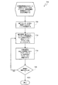
ブロック605で開始し、モニタモジュール114は、たとえばあらかじめ決定された温度しきい値を上回る温度測定値など、熱イベントを、熱エネルギー生成を低減するためのトリガとして認識し得る。前に説明したように、モニタモジュール114は、そのような熱警報情報を、エネルギー効率認識型管理ソリューションの適用のために、EMモジュール101に提供し得る。
Beginning at
ブロック610で、EMモジュール101は、SoCにおける様々なヘテロジニアス処理構成要素に関連付けられた性能データについての問合せを行い得る。モニタモジュール114によってEMモジュール101に提供される動作温度に基づいて、関連する性能データについての問合せが行われ得る。性能データを使用して、EMモジュール101は、作業負荷を効率的に処理するそれらの相対的な能力に基づいて、処理構成要素のランキングを決定し得る。
At
ブロック615で、EMモジュール101は、あらかじめ決定された増分だけ、あまり効率的でない処理コアのうちの1つまたは複数に供給される電力の周波数を低減し得る。特に、周波数の低減が処理構成要素によって処理される作業負荷の量の低減と直接相関することを、当業者は認識する。
At
次に、決定ブロック620で、EMモジュール101は、モニタモジュール114とともに働いて、ブロック610および615をトリガした熱警報が解除されたかどうかを判断し得る。警報が解除された場合、すなわち、ブロック615で実施された周波数の低減が、警報を正常に解除する低減された熱エネルギー生成をもたらした場合、「はい」分岐に進み、方法600が戻る。EMモジュール101は、あまり効率的でない処理コアに供給された周波数の増加を許可し得る。しかしながら、ブロック615でとられたアクションの結果として、警報が解除されなかった場合、「いいえ」分岐はブロック610に戻り、電力周波数の漸進的低減のために、「新たな」エネルギー効率が最も低い処理構成要素が識別される。特に、「新たな」エネルギー効率が最も低い処理構成要素が、エネルギー効率が最も低い処理構成要素として以前識別された同じ処理構成要素であり得ることが理解されよう。ブロック610〜620のループは、熱警報が解除されるまで、エネルギー効率が最も低い処理構成要素に供給された電力の周波数を増分的に低減し続ける。
Next, at
図7は、作業負荷再配分を介した同期のシステムオンチップにおけるエネルギー効率認識型熱管理のための方法700の一実施形態を示す論理フローチャートである。図7の実施形態では、様々な処理コア222、224、226、228の各々の性能曲線は、監視モジュール114によって収集された実際の性能データに基づいて経験的に決定されてよく、またはいくつかの実施形態では、性能曲線は、各コアの性能スペックにより決まる先験的な曲線であってよい。
FIG. 7 is a logic flow diagram illustrating one embodiment of a
いくつかの実施形態では、様々な処理コア222、224、226、228の性能曲線を経験的に決定するために、監視モジュール114は、温度センサ157、ならびにコア222、224、226、228の電力消費を監視するために有用な様々な他の電圧センサまたは電流センサと通信していてよい。そのような実施形態では、モニタモジュール114によって収集されたデータは、以前の作業負荷配分と結合され、経験的な性能曲線へとコンパイルされ得ることは、当業者には認識されよう。経験的な性能曲線は、CPデータストア24に記憶され、エネルギー効率認識型熱管理アルゴリズムによって使用され得る。
In some embodiments, in order to empirically determine the performance curves of the
ブロック705で開始し、モニタモジュール114は、たとえばあらかじめ決定された温度しきい値を上回る温度測定値など、熱イベントを、熱エネルギー生成を低減するためのトリガとして認識し得る。前に説明したように、モニタモジュール114は、そのような熱警報情報を、エネルギー効率認識型管理ソリューションの適用のために、EMモジュール101に提供し得る。
Beginning at
ブロック710で、EMモジュール101は、SoCにおける様々なヘテロジニアス処理構成要素に関連付けられた性能データについての問合せを行い得る。モニタモジュール114によってEMモジュール101に提供される動作温度に基づいて、関連する性能データについての問合せが行われ得る。性能データを使用して、EMモジュール101は、作業負荷を効率的に処理するそれらの相対的な能力に基づいて、処理構成要素のランキングを決定し得る。
At
ブロック715で、EMモジュール101は、あまり効率的でないプロセッサによって処理されているアクティブな作業負荷をより効率的なプロセッサに再配分し得る。特に、あまり効率的でないプロセッサおよびより効率的なプロセッサが共通の電源およびクロックジェネレータを共有する場合であっても、あまり効率的でないプロセッサからより効率的なプロセッサに作業負荷を移動することが、低減した電力量で作業負荷が処理されることにつながり得ることを、当業者は認識されよう。
At
次に、決定ブロック720で、EMモジュール101は、モニタモジュール114とともに働いて、ブロック710および715をトリガした熱警報が解除されたかどうかを判断し得る。警報が解除された場合、すなわち、あまり効率的でないプロセッサからより効率的なプロセッサへの作業負荷の再配分が、警報を正常に解除する低減された熱エネルギー生成をもたらした場合、「はい」分岐に進み、方法700が戻る。EMモジュール101は、あまり効率的でない処理コアへの作業負荷の将来の配分または再配分を許可し得る。しかしながら、ブロック715でとられたアクションの結果として、警報が解除されなかった場合、「いいえ」分岐はブロック710に戻り、作業負荷の低減のために、「新たな」エネルギー効率が最も低い処理構成要素が識別される。特に、「新たな」エネルギー効率が最も低い処理構成要素が、エネルギー効率が最も低い処理構成要素として以前識別された同じ処理構成要素であり得ることが理解されよう。ブロック710〜720のループは、熱警報が解除されるまで、エネルギー効率が最も低い処理構成要素から作業負荷を移動させ続ける。
Next, at
図8は、待ち行列に入れられた作業負荷の配分を介した同期のシステムオンチップにおけるエネルギー効率認識型熱管理のための方法800の一実施形態を示す論理フローチャートである。図8の実施形態では、様々な処理コア222、224、226、228の各々の性能曲線は、監視モジュール114によって収集された実際の性能データに基づいて経験的に決定されてよく、またはいくつかの実施形態では、性能曲線は、各コアの性能スペックにより決まる先験的な曲線であってよい。
FIG. 8 is a logic flow diagram illustrating one embodiment of a
いくつかの実施形態では、様々な処理コア222、224、226、228の性能曲線を経験的に決定するために、監視モジュール114は、温度センサ157、ならびにコア222、224、226、228の電力消費を監視するために有用な様々な他の電圧センサまたは電流センサと通信していてよい。そのような実施形態では、モニタモジュール114によって収集されたデータは、以前の作業負荷配分と結合され、経験的な性能曲線へとコンパイルされ得ることは、当業者には認識されよう。経験的な性能曲線は、CPデータストア24に記憶され、エネルギー効率認識型熱管理アルゴリズムによって使用され得る。
In some embodiments, in order to empirically determine the performance curves of the
ブロック805で開始し、モニタモジュール114は、たとえばあらかじめ決定された温度しきい値を上回る温度測定値など、熱イベントを、熱エネルギー生成を低減するためのトリガとして認識し得る。前に説明したように、モニタモジュール114は、そのような熱警報情報を、エネルギー効率認識型管理ソリューションの適用のために、EMモジュール101に提供し得る。
Beginning at
ブロック810で、EMモジュール101は、SoCにおける様々なヘテロジニアス処理構成要素に関連付けられた性能データについての問合せを行い得る。モニタモジュール114によってEMモジュール101に提供される動作温度に基づいて、関連する性能データについての問合せが行われ得る。性能データを使用して、EMモジュール101は、作業負荷を効率的に処理するそれらの相対的な能力に基づいて、処理構成要素のランキングを決定し得る。
At
ブロック815で、EMモジュール101は、作業負荷を最も効率的に処理するために最良に配置されたプロセッサに待ち行列に入れられた作業負荷を配分するようスケジューラ207に命令し得る。特に、作業負荷をより効率的なプロセッサに配分することが、低減した電力量で作業負荷が処理されることにつながり得ることを、当業者は認識されよう。
At
特に、EMモジュール101は、モニタモジュール114とともに働いて、作業負荷の配分のための「新たな」より効率的な処理構成要素を識別し続けることができる。特に、「新たな」より効率的な処理構成要素が、より効率的な処理構成要素として以前識別された同じ処理構成要素であり得ることが理解されよう。このようにして、方法800のエネルギー効率認識型熱管理ソリューションは、新たな作業負荷が、最少の電力量を消費するために処理時に最良に配置された処理構成要素にスケジュールされることを、継続的に確実にすることができる。
In particular, the
図9は、電力モード調整を介した同期のシステムオンチップにおけるエネルギー効率認識型熱管理のための方法900の一実施形態を示す論理フローチャートである。図9の実施形態では、様々な処理コア222、224、226、228の各々の性能曲線は、監視モジュール114によって収集された実際の性能データに基づいて経験的に決定されてよく、またはいくつかの実施形態では、性能曲線は、各コアの性能スペックにより決まる先験的な曲線であってよい。
FIG. 9 is a logic flow diagram illustrating one embodiment of a
いくつかの実施形態では、様々な処理コア222、224、226、228の性能曲線を経験的に決定するために、監視モジュール114は、温度センサ157、ならびにコア222、224、226、228の電力消費を監視するために有用な様々な他の電圧センサまたは電流センサと通信していてよい。そのような実施形態では、モニタモジュール114によって収集されたデータは、以前の作業負荷配分と結合され、経験的な性能曲線へとコンパイルされ得ることは、当業者には認識されよう。経験的な性能曲線は、CPデータストア24に記憶され、エネルギー効率認識型熱管理アルゴリズムによって使用され得る。
In some embodiments, in order to empirically determine the performance curves of the
ブロック905で開始し、モニタモジュール114は、たとえばあらかじめ決定された温度しきい値を上回る温度測定値など、熱イベントを、熱エネルギー生成を低減するためのトリガとして認識し得る。前に説明したように、モニタモジュール114は、そのような熱警報情報を、エネルギー効率認識型管理ソリューションの適用のために、EMモジュール101に提供し得る。
Beginning at
ブロック910で、EMモジュール101は、SoCにおける様々なヘテロジニアス処理構成要素に関連付けられた性能データについての問合せを行い得る。モニタモジュール114によってEMモジュール101に提供される動作温度に基づいて、関連する性能データについての問合せが行われ得る。性能データを使用して、EMモジュール101は、作業負荷を効率的に処理するそれらの相対的な能力に基づいて、処理構成要素のランキングを決定し得る。
At
ブロック915で、EMモジュール101は、不必要な電力消費を低減しようとして、あまり効率的でないプロセッサの電力モードを調整し得る。EMモジュール101は、限定はしないが、所与のアイドル状態電力モードからアクティブ電力モードに移行しているプロセッサに関連付けられたレイテンシを含む様々なパラメータに基づいてその電力モードを調整させるために最良に配置されたプロセッサを識別し得ると想定される。特に、プロセッサの電力モードをアクティブモードから保持モードまたは電力縮小モードに調整することが、SoCにわたる電力消費の平均的な節約をもたらし得ることを、当業者は認識されよう。
At
次に、決定ブロック920で、EMモジュール101は、モニタモジュール114とともに働いて、ブロック910および915をトリガした熱警報が解除されたかどうかを判断し得る。警報が解除された場合、すなわち、エネルギー効率が最も低いプロセッサの電力モードを調整することが警報を正常に解除する低減された熱エネルギー生成をもたらした場合、「はい」分岐に進み、方法900が戻る。EMモジュール101は、あまり効率的でない処理コアについてより高い電力消費モードに戻ることを許可し得る。しかしながら、ブロック915でとられたアクションの結果として、警報が解除されなかった場合、「いいえ」分岐はブロック910に戻り、電力モードの移行のために、「新たな」エネルギー効率が最も低い処理構成要素が識別される。特に、「新たな」エネルギー効率が最も低い処理構成要素が、エネルギー効率が最も低い処理構成要素として以前識別された同じ処理構成要素であり得ることが理解されよう。
Next, at
図10は、電力モードデューティサイクリングを介した同期のシステムオンチップにおけるエネルギー効率認識型熱管理のための方法1000の一実施形態を示す論理フローチャートである。図10の実施形態では、様々な処理コア222、224、226、228の各々の性能曲線は、監視モジュール114によって収集された実際の性能データに基づいて経験的に決定されてよく、またはいくつかの実施形態では、性能曲線は、各コアの性能スペックにより決まる先験的な曲線であってよい。
FIG. 10 is a logic flow diagram illustrating one embodiment of a
いくつかの実施形態では、様々な処理コア222、224、226、228の性能曲線を経験的に決定するために、監視モジュール114は、温度センサ157、ならびにコア222、224、226、228の電力消費を監視するために有用な様々な他の電圧センサまたは電流センサと通信していてよい。そのような実施形態では、モニタモジュール114によって収集されたデータは、以前の作業負荷配分と結合され、経験的な性能曲線へとコンパイルされ得ることは、当業者には認識されよう。経験的な性能曲線は、CPデータストア24に記憶され、エネルギー効率認識型熱管理アルゴリズムによって使用され得る。
In some embodiments, in order to empirically determine the performance curves of the
ブロック1005で開始し、モニタモジュール114は、たとえばあらかじめ決定された温度しきい値を上回る温度測定値など、熱イベントを、熱エネルギー生成を低減するためのトリガとして認識し得る。前に説明したように、モニタモジュール114は、そのような熱警報情報を、エネルギー効率認識型管理ソリューションの適用のために、EMモジュール101に提供し得る。
Beginning at
ブロック1010で、EMモジュール101は、SoCにおける様々なヘテロジニアス処理構成要素に関連付けられた性能データについての問合せを行い得る。モニタモジュール114によってEMモジュール101に提供される動作温度に基づいて、関連する性能データについての問合せが行われ得る。性能データを使用して、EMモジュール101は、作業負荷を効率的に処理するそれらの相対的な能力に基づいて、処理構成要素のランキングを決定し得る。
At
ブロック1015で、EMモジュール101は、不必要な電力消費を低減しようとして、あまり効率的でないプロセッサの電力モードを循環させ得る。電力モードを循環させることによって、プロセッサは、たとえば、保持状態とアクティブ状態との間でトグルするなど、その様々な電力モードを移行することができる。ある時間期間の間、複数の低電力モードの各々で静止することによって、処理構成要素による平均電力消費が最適化され得る。EMモジュール101は、限定はしないが、所与のアイドル状態電力モードから別の電力モードに移行しているプロセッサに関連付けられたレイテンシを含む様々なパラメータに基づいてその電力モードを循環させるために最良に配置されたプロセッサを識別し得ると想定される。特に、プロセッサにその電力モードを循環させることが、サイクルプロセッサの処理能力を完全に犠牲にすることなく、SoCにわたる電力消費の平均的な節約をもたらし得ることを、当業者は認識されよう。
At
次に、決定ブロック1020で、EMモジュール101は、モニタモジュール114とともに働いて、ブロック1010および1015をトリガした熱警報が解除されたかどうかを判断し得る。警報が解除された場合、すなわち、エネルギー効率が最も低いプロセッサの電力モードを循環させることが警報を正常に解除する低減された熱エネルギー生成をもたらした場合、「はい」分岐に進み、方法1000が戻る。EMモジュール101は、あまり効率的でない処理コアについて電力モードのデューティサイクルをやめることを許可し得る。しかしながら、ブロック1015でとられたアクションの結果として、警報が解除されなかった場合、「いいえ」分岐はブロック1010に戻り、電力モードの循環のために、「新たな」エネルギー効率が最も低い処理構成要素が識別される。特に、「新たな」エネルギー効率が最も低い処理構成要素が、エネルギー効率が最も低い処理構成要素として以前識別された同じ処理構成要素であり得ることが理解されよう。
Next, at
図11は、処理構成要素エネルギー効率レーティングの実行時検証のための方法1100の一実施形態を示す論理フローチャートである。エネルギー効率認識型熱管理ソリューションの例示的な実施形態に関して上述したように、様々なヘテロジニアス処理構成要素に関連付けられた性能データは、処理構成要素のうちのどれが、作業負荷を処理する際にエネルギー効率が最も低いかを判断するために使用され得る(処理構成要素に対する電力周波数が処理構成要素の処理能力と直接相関すると仮定すれば、エネルギー効率はMIPS/mWまたはMHz/mWで測定され得る)。性能データは、監視モジュール114によって収集された実際の性能データに基づいて経験的に決定されてよく、またはいくつかの実施形態では、性能曲線は、各コアの性能スペックによって決まる先験的な曲線であってよい。
FIG. 11 is a logic flow diagram illustrating one embodiment of a
特に、処理構成要素が時間とともに消耗するにつれて、処理構成要素の性能仕様から導出される先験的な性能データは正確ではない、またはその精度を失う可能性がある。したがって、方法1100の実施形態は、エネルギー効率認識型熱管理ソリューションがエネルギー効率に関する決定を行うために性能データに依存する前に所与の処理コアに関連付けられた性能データの妥当性を検査しようとする。
In particular, as processing components wear out over time, a priori performance data derived from processing component performance specifications may be inaccurate or lose its accuracy. Thus, embodiments of the
モニタモジュール114および/またはEMモジュール101は、チップ102の周りの電流センサおよび温度センサにアクセスし得るので、また、EMモジュール101は、CPデータストア24に記憶された、以前プロファイリングされた性能データについて問合せを行い得るので、方法1100の実施形態は、処理構成要素に関連付けられた記憶された性能データの精度を検査し、必要に応じて、それを更新するために使用され得る。関連の電流測定値および温度測定値は、サンプリングされ、処理構成要素またはサブシステムが予想された電流漏洩特性をアクティブに呈しているかどうかを判断するために、記憶された性能データと比較され得る。
ブロック1105で、モニタモジュール114は、特定の処理構成要素に関連付けられた電流、動作温度、および動作点(たとえば、電力周波数設定MHz)を監視し得る。ブロック1110で、EMモジュール101は、ブロック1105でモニタモジュール114によって測定された動作温度および動作点に基づいて、記憶された性能データについて問合せを行い得る。記憶された性能データは、処理構成要素の性能仕様、動作点、および動作温度を鑑みて予想された電流レベルを含み得る。
At
次に、ブロック1115で、EMモジュール101は、予想された電流漏洩を測定された電流漏洩と比較し得る。決定ブロック1120で、予想された電流漏洩が実際の測定された漏洩よりも大きい場合、「はい」分岐はブロック1140に進み、処理構成要素は、その最初の分類に対してより低い漏洩プロセッサと指定される。CPストア24内の処理構成要素に関連付けられた予想された電流漏洩は、実際の測定された電流漏洩を反映するために更新され得る。方法1100は戻る。
Next, at
決定ブロック1120に戻って、予想された電流漏洩が実際の測定された電流漏洩よりも大きくない場合、「いいえ」分岐は決定ブロック1125に進む。決定ブロック1125で、予想された電流漏洩が、許容できる統計的有意性の何らかの範囲内で、実際の測定された電流漏洩に実質的に等しい場合、「はい」分岐はブロック1135に進み、処理構成要素の分類が維持される。方法1100は戻る。
Returning to
決定ブロック1125で予想された電流漏洩が実際の測定された電流漏洩に実質的には等しくない場合、すなわち、予想された電流漏洩が実際の測定された電流漏洩よりも低い場合、「いいえ」分岐はブロック1130に進む。ブロック1130で、処理構成要素は、その最初の分類に対してより高い漏洩プロセッサと指定される。CPストア24内の処理構成要素に関連付けられた予想された電流漏洩は、実際の測定された電流漏洩を反映するために更新され得る。方法1100は戻る。
If the expected current leakage in
有利には、処理構成要素の相対的な漏洩分類を検証し、更新することによって、エネルギー効率認識型熱管理ソリューションは、どの処理構成要素が、熱軽減手段を適用する前の他の処理構成要素よりもより効率的であるか、またはあまり効率的でないかに関する評価を行う能力をより備え得る。 Advantageously, by verifying and updating the relative leakage classification of the processing components, the energy efficiency aware thermal management solution allows any processing component to be applied to other processing components prior to applying the thermal mitigation measures. It may be more capable of making an assessment as to whether it is more efficient or less efficient.
本発明が説明されたように機能するために、本明細書において説明されるプロセスまたはプロセスフローにおけるいくつかのステップが、他のステップに先行するのは当然である。しかしながら、そのような順序またはシーケンスが本発明の機能を変えない場合、本発明は、説明されたステップの順序に限定されない。すなわち、本発明の範囲および趣旨から逸脱することなく、いくつかのステップは、他のステップの前に実行される場合があるか、後に実行される場合があるか、または他のステップと並行して(実質的に同時に)実行される場合があることを認識されたい。場合によっては、本発明から逸脱することなく、いくつかのステップは、省略される場合があるか、または実行されない場合がある。さらに、「後に」、「次いで」、「次に」などの言葉は、ステップの順序を限定することを意図していない。これらの言葉は単に、例示的な方法の説明を通して読者を導くために使用される。 Of course, some steps in the process or process flow described herein precede other steps in order for the present invention to function as described. However, the invention is not limited to the described order of steps if such order or sequence does not change the function of the invention. That is, some steps may be performed before, after, or in parallel with other steps without departing from the scope and spirit of the present invention. It should be recognized that (substantially simultaneously) may be performed. In some cases, some steps may be omitted or not performed without departing from the invention. Furthermore, terms such as “after”, “next”, “next” are not intended to limit the order of the steps. These terms are only used to guide the reader through the description of exemplary methods.
さらに、プログラミングに関する当業者は、たとえば、本明細書における流れ図および関連する説明に基づいて、難なく、開示される発明を実施するコンピュータコードを書くことができるか、または実施するのに適したハードウェアおよび/もしくは回路を特定することができる。したがって、特定の1つのセットのプログラムコード命令または詳細なハードウェアデバイスの開示は、本発明の作製方法および使用方法を十分に理解するのに必要であるとは見なされない。特許請求されるコンピュータ実施のプロセスの本発明の機能性については、上述の説明において、様々な処理フローを示し得る図面と一緒に、より詳細に説明されている。 Moreover, those skilled in the art of programming can, without difficulty, write computer code that implements the disclosed invention or that is suitable for implementing, for example, based on the flowcharts and associated descriptions herein. And / or a circuit can be specified. Thus, disclosure of a particular set of program code instructions or detailed hardware devices is not deemed necessary to fully understand the methods of making and using the present invention. The inventive functionality of the claimed computer-implemented process is described in greater detail in the foregoing description, along with drawings that may show various process flows.
1つまたは複数の例示的な態様では、説明される機能は、ハードウェア、ソフトウェア、ファームウェア、またはそれらの任意の組合せにおいて実装することができる。ソフトウェアにおいて実装される場合、機能は、1つまたは複数の命令またはコードとして、コンピュータ可読媒体上に記憶される場合があるか、またはコンピュータ可読媒体上に送信される場合がある。コンピュータ可読媒体は、コンピュータ記憶媒体と、コンピュータプログラムの1つの場所から別の場所への転送を容易する任意の媒体を含む通信媒体の両方を含む。記憶媒体は、コンピュータによってアクセスされる場合がある任意の利用可能な媒体であってもよい。例であって、限定はしないが、そのようなコンピュータ可読媒体は、RAM、ROM、EEPROM、CD-ROMもしくは他の光ディスク記憶装置、磁気ディスク記憶装置もしくは他の磁気記憶デバイス、または命令またはデータ構造の形態で所望のプログラムコードを搬送または記憶するために使用することができ、コンピュータによってアクセスすることができる任意の他の媒体を含むことができる。 In one or more exemplary aspects, the functions described can be implemented in hardware, software, firmware, or any combination thereof. If implemented in software, the functions may be stored on or transmitted over as one or more instructions or code on a computer-readable medium. Computer-readable media includes both computer storage media and communication media including any medium that facilitates transfer of a computer program from one place to another. A storage media may be any available media that may be accessed by a computer. By way of example and not limitation, such computer readable media can be RAM, ROM, EEPROM, CD-ROM or other optical disk storage, magnetic disk storage or other magnetic storage device, or instructions or data structure Any other medium that can be used to carry or store the desired program code in the form of and can be accessed by a computer can be included.
また、任意の接続部も、厳密にはコンピュータ可読媒体と呼ばれる。たとえば、ソフトウェアが、同軸ケーブル、光ファイバケーブル、ツイストペア、デジタル加入者回線(「DSL」)、または、赤外線、無線、およびマイクロ波などのワイヤレス技術を使用して、ウェブサイト、サーバ、または他のリモートソースから送信される場合には、同軸ケーブル、光ファイバケーブル、ツイストペア、DSL、または、赤外線、無線、およびマイクロ波などのワイヤレス技術は、媒体の定義に含まれる。 Also, any connection is strictly called a computer readable medium. For example, the software uses a coaxial cable, fiber optic cable, twisted pair, digital subscriber line (“DSL”), or wireless technology such as infrared, wireless, and microwave to use a website, server, or other When transmitted from a remote source, coaxial cable, fiber optic cable, twisted pair, DSL, or wireless technologies such as infrared, radio, and microwave are included in the definition of the medium.
ディスク(disk)およびディスク(disc)は、本明細書において使用されるときに、コンパクトディスク(disc)(CD)、レーザディスク(disc)、光ディスク(disc)、デジタル多用途ディスク(disc)(DVD)、フロッピーディスク(disk)およびブルーレイディスク(disc)を含み、ディスク(disk)は通常、データを磁気的に再生するが、ディスク(disc)は、レーザを用いてデータを光学的に再生する。上記のものの組合せも、コンピュータ可読媒体の範囲内に含まれるべきである。 Disc and disc as used herein are compact disc (CD), laser disc (disc), optical disc (disc), digital versatile disc (DVD) ), Floppy disk and Blu-ray disc, which normally reproduces data magnetically, but the disc optically reproduces data using a laser. Combinations of the above should also be included within the scope of computer-readable media.
したがって、選択された態様が図示され詳細に説明されてきたが、以下の特許請求の範囲によって規定されるように、本発明の趣旨および範囲から逸脱することなく、態様において種々の置換および改変が行われる場合があることは理解されよう。 Accordingly, although selected aspects have been shown and described in detail, various substitutions and modifications may be made in the aspects without departing from the spirit and scope of the invention, as defined by the following claims. It will be understood that this may be done.
24 コア性能データストア
26 DCVSモジュール
100 ポータブルコンピューティングデバイス(「PCD」)
101 効率マネージャ(「EM」)モジュール
102 オンチップシステム
103 ADCコントローラ
110 CPU
110 デジタル信号プロセッサ
112 メモリ
114 モニタモジュール
126 アナログ信号プロセッサ
128 ディスプレイコントローラ
130 タッチスクリーンコントローラ
132 タッチスクリーンディスプレイ
134 ビデオデコーダ
135 グラフィックプロセッサ
136 ビデオ増幅器
138 ビデオポート
140 ユニバーサルシリアルバス(「USB」)コントローラ
142 USBポート
146 加入者識別モジュール(SIM)カード
148 デジタルカメラ
150 ステレオオーディオコーデック
152 オーディオ増幅器
154 第1のステレオスピーカ
156 第2のステレオスピーカ
157 温度センサ
158 マイクロフォン増幅器
160 マイクロフォン
162 周波数変調(FM)ラジオチューナ
164 FMアンテナ
166 ステレオヘッドフォン
168 無線周波数(RF)トランシーバ
170 RFスイッチ
172 RFアンテナ
173 デジタルアナログコントローラ
174 キーパッド
176 マイクロフォン付きモノヘッドセット
177 縮小命令セットコンピュータ(「RISC」)命令セットマシン(「ARM」)
178 バイブレータデバイス
180 電源
207 スケジューラモジュール
208 オペレーティングシステム(「O/S」)モジュール
209 位相ロックループ(「PLL」)
211 バス
222 コア
224 コア
226 コア
228 コア
230 コア
250 開始論理
260 管理論理
270 エネルギー効率認識型熱管理インターフェース論理
280 アプリケーションストア
290 ファイルシステム
296 プログラムストア
24 core performance data store
26 DCVS module
100 portable computing devices (`` PCD '')
101 Efficiency Manager (“EM”) module
102 On-chip system
103 ADC controller
110 CPU
110 digital signal processor
112 memory
114 Monitor module
126 analog signal processor
128 display controller
130 Touch screen controller
132 Touch screen display
134 Video decoder
135 graphics processor
136 Video amplifier
138 video port
140 Universal Serial Bus (“USB”) controller
142 USB port
146 Subscriber Identification Module (SIM) card
148 Digital camera
150 stereo audio codecs
152 audio amplifier
154 First stereo speaker
156 Second stereo speaker
157 Temperature sensor
158 Microphone amplifier
160 microphone
162 Frequency modulation (FM) radio tuner
164 FM antenna
166 Stereo headphones
168 radio frequency (RF) transceiver
170 RF switch
172 RF antenna
173 Digital analog controller
174 keypad
176 Mono headset with microphone
177 Reduced Instruction Set Computer (`` RISC '') Instruction Set Machine (`` ARM '')
178 Vibrator device
180 power supply
207 Scheduler module
208 Operating system (`` O / S '') module
209 Phase-locked loop (`` PLL '')
211 Bus
222 core
224 core
226 core
228 core
230 cores
250 start logic
260 Management logic
270 Energy Efficiency Aware Thermal Management Interface Logic
280 Application Store
290 file system
296 Program Store
Claims (26)
前記マルチプロセッサSoCにおける複数の個々の処理構成要素の各々に一意に関連付けられた温度測定値を監視するステップであり、各処理構成要素が、専用の電源電圧およびクロックジェネレータ周波数に関連付けられる、ステップと、
前記ポータブルコンピューティングデバイスの少なくとも1つの熱パラメータを監視するステップと、
前記ポータブルコンピューティングデバイスの前記監視された熱パラメータがあらかじめ決定されたしきい値を超えたことに応答して、警報を生成するステップと、
前記警報に応答して、前記処理構成要素の各々に一意に関連付けられた前記監視された温度測定値をサンプリングするステップと、
前記サンプリングされた温度測定値に基づいて、各処理構成要素についての性能データの問合せを行うステップであり、前記性能データが、所与の個々の処理構成要素の、所与の温度で動作しているときの電力消費と作業負荷処理能力との間の関係を表す、ステップと、
前記マルチプロセッサSoCにおいてエネルギー効率が最も低い処理構成要素を識別するために、各処理構成要素についての前記性能データを比較するステップと、
前記エネルギー効率が最も低い処理構成要素の前記専用の電源電圧およびクロックジェネレータ周波数を調整するステップであり、前記エネルギー効率が最も低い処理構成要素による前記電力消費を低減するように動作するステップと
を含み、
前記方法は、さらに、
前記警報が解除されなかったことを決定するステップと、
前記処理構成要素の各々に一意に関連付けられた前記監視された温度測定値を再サンプリングするステップと、
前記再サンプリングされた温度測定値に基づいて、各処理構成要素についての性能データの再問合せを行うステップと、
新たなエネルギー効率が最も低い処理構成要素を識別するために、各処理構成要素についての前記再問合わせされた性能データを比較するステップと、
前記新たなエネルギー効率が最も低い処理構成要素の前記専用の電源電圧およびクロックジェネレータ周波数を調整するステップであり、前記新たなエネルギー効率が最も低い処理構成要素による前記電力消費を低減するように動作するステップと
を含む、方法。 A method for managing thermal energy generation in a portable computing device having an asynchronous multiprocessor system on chip (`` SoC '') comprising:
Monitoring a temperature measurement uniquely associated with each of a plurality of individual processing components in the multiprocessor SoC, each processing component being associated with a dedicated power supply voltage and a clock generator frequency; and ,
Monitoring at least one thermal parameter of the portable computing device;
Generating an alert in response to the monitored thermal parameter of the portable computing device exceeding a predetermined threshold;
In response to the alarm, sampling the monitored temperature measurement uniquely associated with each of the processing components;
Querying performance data for each processing component based on the sampled temperature measurements, wherein the performance data is operating at a given temperature for a given individual processing component. Steps representing the relationship between power consumption and workload processing capacity when
Comparing the performance data for each processing component to identify the least energy efficient processing component in the multiprocessor SoC;
Adjusting the dedicated power supply voltage and clock generator frequency of the processing component with the lowest energy efficiency, and operating to reduce the power consumption by the processing component with the lowest energy efficiency. ,
The method further comprises:
Determining that the alarm has not been released;
Re-sampling the monitored temperature measurements uniquely associated with each of the processing components;
Re-querying performance data for each processing component based on the resampled temperature measurements;
Comparing the re-queried performance data for each processing component to identify the new least energy efficient processing component;
Adjusting the dedicated power supply voltage and clock generator frequency of the new energy-efficient processing component, and operating to reduce the power consumption by the new energy-efficient processing component A method comprising steps and.
前記エネルギー効率が最も低い処理構成要素に対する前記電源電圧およびクロックジェネレータ周波数の増加を許可するステップと
をさらに含む、請求項1に記載の方法。 Determining that the alarm has been released;
The method of claim 1, further comprising: allowing the power supply voltage and clock generator frequency to increase for the processing component with the lowest energy efficiency.
をさらに含む、請求項1に記載の方法。 The method of claim 1, further comprising: transitioning a power mode of the least energy efficient processor from an active mode to an idle mode.
前記エネルギー効率が最も低いプロセッサについてアクティブ電力モードに戻ることを許可するステップと
をさらに含む、請求項4に記載の方法。 Determining that the alarm has been released;
Allowing the processor with the lowest energy efficiency to return to active power mode.
前記マルチプロセッサSoCにおける複数の個々の処理構成要素の各々に一意に関連付けられた温度測定値を監視することであり、各処理構成要素が、専用の電源電圧およびクロックジェネレータ周波数に関連付けられる、監視することと、
前記ポータブルコンピューティングデバイスの少なくとも1つの熱パラメータを監視することと、
前記ポータブルコンピューティングデバイスの前記監視された熱パラメータがあらかじめ決定されたしきい値を超えたことに応答して、警報を生成することと、
前記警報に応答して、前記処理構成要素の各々に一意に関連付けられた前記監視された温度測定値をサンプリングすることと
を行うためのモニタモジュールと、
前記サンプリングされた温度測定値に基づいて、各処理構成要素についての性能データの問合せを行うことであり、前記性能データが、所与の個々の処理構成要素の、所与の温度で動作しているときの電力消費と作業負荷処理能力との間の関係を表す、問合せを行うことと、
前記マルチプロセッサSoCにおいてエネルギー効率が最も低い処理構成要素を識別するために、各処理構成要素についての前記性能データを比較することと
を行うための効率マネージャ(「EM」)モジュールと、
前記エネルギー効率が最も低い処理構成要素の前記専用の電源電圧およびクロックジェネレータ周波数を調整することであり、前記エネルギー効率が最も低い処理構成要素による前記電力消費を低減するように動作する、調整すること
を行うための動的制御および電圧スケーリング(「DCVS」)モジュールと
を含み、
前記モニタモジュールが、さらに、
前記警報が解除されなかったことを決定し、
前記処理構成要素の各々に一意に関連付けられた前記監視された温度測定値を再サンプリングする
ためのものであり、
前記EMモジュールが、さらに、
前記再サンプリングされた温度測定値に基づいて、各処理構成要素についての性能データの再問合せを行い、
新たなエネルギー効率が最も低い処理構成要素を識別するために、各処理構成要素についての前記再問合わせされた性能データを比較する
ためのものであり、
前記DCVSモジュールが、さらに、
前記新たなエネルギー効率が最も低い処理構成要素の前記専用の電源電圧およびクロックジェネレータ周波数を調整することであり、前記新たなエネルギー効率が最も低い処理構成要素による前記電力消費を低減するように動作する、調整すること
を行うためのものである、コンピュータシステム。 A computer system for managing thermal energy generation in a portable computing device having an asynchronous multiprocessor system-on-chip (“SoC”) comprising:
Monitoring temperature measurements uniquely associated with each of a plurality of individual processing components in the multiprocessor SoC, each processing component being associated with a dedicated power supply voltage and clock generator frequency And
Monitoring at least one thermal parameter of the portable computing device;
Generating an alert in response to the monitored thermal parameter of the portable computing device exceeding a predetermined threshold;
In response to the alarm, sampling the monitored temperature measurement uniquely associated with each of the processing components; and
Querying performance data for each processing component based on the sampled temperature measurements, wherein the performance data is operating at a given temperature for a given individual processing component. Querying to represent the relationship between power consumption and workload processing capacity when
An efficiency manager (“EM”) module for comparing the performance data for each processing component to identify the processing component with the lowest energy efficiency in the multiprocessor SoC;
Adjusting the dedicated power supply voltage and clock generator frequency of the processing component with the lowest energy efficiency, and adjusting to operate to reduce the power consumption by the processing component with the lowest energy efficiency A dynamic control and voltage scaling (`` DCVS '') module to perform
The monitor module further comprises:
Determining that the alarm was not released,
Re-sampling the monitored temperature measurements uniquely associated with each of the processing components;
The EM module further comprises:
Based on the resampled temperature measurements, requery performance data for each processing component;
For comparing the requeried performance data for each processing component to identify the new energy-efficient processing component;
The DCVS module further comprises:
Adjusting the dedicated power supply voltage and clock generator frequency of the new energy-efficient processing component to operate to reduce the power consumption by the new energy-efficient processing component A computer system that is intended to make adjustments.
前記警報が解除されたことを決定する
ためのものであり、
前記EMモジュールが、さらに、
前記エネルギー効率が最も低い処理構成要素に対する前記電源電圧およびクロックジェネレータ周波数の増加を許可する
ためのものである、
請求項8に記載のコンピュータシステム。 The monitor module further comprises:
For determining that the alarm has been released,
The EM module further comprises:
To allow an increase in the power supply voltage and clock generator frequency for the processing component with the lowest energy efficiency;
The computer system according to claim 8.
前記エネルギー効率が最も低いプロセッサの電力モードをアクティブモードからアイドルモードに移行する
ためのものである、
請求項8に記載のコンピュータシステム。 The monitor module further comprises:
For transitioning the power mode of the lowest energy efficient processor from active mode to idle mode,
The computer system according to claim 8.
前記警報が解除されたことを決定する
ためのものであり、
前記EMモジュールが、さらに、
前記エネルギー効率が最も低いプロセッサについてアクティブ電力モードに戻ることを許可する
ためのものである
請求項11に記載のコンピュータシステム。 The monitor module further comprises:
For determining that the alarm has been released,
The EM module further comprises:
12. The computer system according to claim 11, wherein the computer system is to allow the processor with the lowest energy efficiency to return to an active power mode.
前記マルチプロセッサSoCにおける複数の個々の処理構成要素の各々に一意に関連付けられた温度測定値を監視するための手段であり、各処理構成要素が、専用の電源電圧およびクロックジェネレータ周波数に関連付けられる、手段と、
前記ポータブルコンピューティングデバイスの少なくとも1つの熱パラメータを監視するための手段と、
前記ポータブルコンピューティングデバイスの前記監視された熱パラメータがあらかじめ決定されたしきい値を超えたことに応答して、警報を生成するための手段と、
前記警報に応答して、前記処理構成要素の各々に一意に関連付けられた前記監視された温度測定値をサンプリングするための手段と、
前記サンプリングされた温度測定値に基づいて、各処理構成要素についての性能データの問合せを行うための手段であり、前記性能データが、所与の個々の処理構成要素の、所与の温度で動作しているときの電力消費と作業負荷処理能力との間の関係を表す、手段と、
前記マルチプロセッサSoCにおいてエネルギー効率が最も低い処理構成要素を識別するために、各処理構成要素についての前記性能データを比較するための手段と、
前記エネルギー効率が最も低い処理構成要素の前記専用の電源電圧およびクロックジェネレータ周波数を調整するための手段であり、前記専用の電源電圧およびクロックジェネレータ周波数を調整することが、前記エネルギー効率が最も低い処理構成要素による前記電力消費を低減するように動作する、手段と
を含み、
前記コンピュータシステムが、さらに、
前記警報が解除されなかったことを決定するための手段と、
前記処理構成要素の各々に一意に関連付けられた前記監視された温度測定値を再サンプリングするための手段と、
前記再サンプリングされた温度測定値に基づいて、各処理構成要素についての性能データの再問合せを行うための手段と、
新たなエネルギー効率が最も低い処理構成要素を識別するために、各処理構成要素についての前記再問合わせされた性能データを比較するための手段と、
前記新たなエネルギー効率が最も低い処理構成要素の前記専用の電源電圧およびクロックジェネレータ周波数を調整するための手段であり、前記専用の電源電圧およびクロックジェネレータ周波数を調整することが、前記新たなエネルギー効率が最も低い処理構成要素による前記電力消費を低減するように動作する、手段と
をさらに含む、コンピュータシステム。 A computer system for managing thermal energy generation in a portable computing device having an asynchronous multiprocessor system-on-chip (“SoC”) comprising:
Means for monitoring a temperature measurement uniquely associated with each of a plurality of individual processing components in the multiprocessor SoC, each processing component being associated with a dedicated power supply voltage and clock generator frequency; Means,
Means for monitoring at least one thermal parameter of the portable computing device;
Means for generating an alert in response to the monitored thermal parameter of the portable computing device exceeding a predetermined threshold;
Means for sampling the monitored temperature measurements uniquely associated with each of the processing components in response to the alarm;
Means for querying performance data for each processing component based on the sampled temperature measurements, the performance data operating at a given temperature of a given individual processing component Means to represent the relationship between power consumption and workload processing capacity when
Means for comparing the performance data for each processing component to identify the least energy efficient processing component in the multiprocessor SoC;
Means for adjusting the dedicated power supply voltage and clock generator frequency of the processing component having the lowest energy efficiency, wherein adjusting the dedicated power supply voltage and clock generator frequency is the process having the lowest energy efficiency. Means for operating to reduce said power consumption by a component, and
The computer system further comprises:
Means for determining that the alarm has not been released;
Means for resampling the monitored temperature measurements uniquely associated with each of the processing components;
Means for re-querying performance data for each processing component based on the resampled temperature measurements;
Means for comparing the re-queried performance data for each processing component to identify new energy-efficient processing components;
Means for adjusting the dedicated power supply voltage and clock generator frequency of the processing component having the lowest new energy efficiency, wherein adjusting the dedicated power supply voltage and clock generator frequency is the new energy efficiency. And a means for operating to reduce the power consumption by the lowest processing component.
前記エネルギー効率が最も低い処理構成要素に対する前記電源電圧およびクロックジェネレータ周波数の増加を許可するための手段と
をさらに含む、請求項14に記載のコンピュータシステム。 Means for determining that the alarm has been released;
15. The computer system of claim 14, further comprising: means for allowing an increase in the power supply voltage and clock generator frequency for the least energy efficient processing component.
をさらに含む、請求項14に記載のコンピュータシステム。 15. The computer system of claim 14, further comprising means for transitioning a power mode of the least energy efficient processor from an active mode to an idle mode.
前記エネルギー効率が最も低いプロセッサについてアクティブ電力モードに戻ることを許可するための手段と
をさらに含む、請求項17に記載のコンピュータシステム。 Means for determining that the alarm has been released;
18. The computer system of claim 17, further comprising: means for allowing the processor with the lowest energy efficiency to return to active power mode.
前記マルチプロセッサSoCにおける複数の個々の処理構成要素の各々に一意に関連付けられた温度測定値を監視するステップであり、各処理構成要素が、専用の電源電圧およびクロックジェネレータ周波数に関連付けられる、ステップと、
前記ポータブルコンピューティングデバイスの少なくとも1つの熱パラメータを監視するステップと、
前記ポータブルコンピューティングデバイスの前記監視された熱パラメータがあらかじめ決定されたしきい値を超えたことに応答して、警報を生成するステップと、
前記警報に応答して、前記処理構成要素の各々に一意に関連付けられた前記監視された温度測定値をサンプリングするステップと、
前記サンプリングされた温度測定値に基づいて、各処理構成要素についての性能データの問合せを行うステップであり、前記性能データが、所与の個々の処理構成要素の、所与の温度で動作しているときの電力消費と作業負荷処理能力との間の関係を表す、ステップと、
前記マルチプロセッサSoCにおいてエネルギー効率が最も低い処理構成要素を識別するために、各処理構成要素についての前記性能データを比較するステップと、
前記エネルギー効率が最も低い処理構成要素の前記専用の電源電圧およびクロックジェネレータ周波数を調整するステップであり、前記エネルギー効率が最も低い処理構成要素による前記電力消費を低減するように動作するステップと
を含み、
前記方法が、さらに、
前記警報が解除されなかったことを決定するステップと、
前記処理構成要素の各々に一意に関連付けられた前記監視された温度測定値を再サンプリングするステップと、
前記再サンプリングされた温度測定値に基づいて、各処理構成要素についての性能データの再問合せを行うステップと、
新たなエネルギー効率が最も低い処理構成要素を識別するために、各処理構成要素についての前記再問合わせされた性能データを比較するステップと、
前記新たなエネルギー効率が最も低い処理構成要素の前記専用の電源電圧およびクロックジェネレータ周波数を調整するステップであり、前記新たなエネルギー効率が最も低い処理構成要素による前記電力消費を低減するように動作する、調整するステップと
を含む、コンピュータ使用可能記憶媒体。 A computer usable storage medium storing computer readable program code for managing thermal energy generation in a portable computing device having an asynchronous multiprocessor system on chip ("SoC"). Adapted to be performed to perform a method, said method comprising:
Monitoring a temperature measurement uniquely associated with each of a plurality of individual processing components in the multiprocessor SoC, each processing component being associated with a dedicated power supply voltage and a clock generator frequency; and ,
Monitoring at least one thermal parameter of the portable computing device;
Generating an alert in response to the monitored thermal parameter of the portable computing device exceeding a predetermined threshold;
In response to the alarm, sampling the monitored temperature measurement uniquely associated with each of the processing components;
Querying performance data for each processing component based on the sampled temperature measurements, wherein the performance data is operating at a given temperature for a given individual processing component. Steps representing the relationship between power consumption and workload processing capacity when
Comparing the performance data for each processing component to identify the least energy efficient processing component in the multiprocessor SoC;
Adjusting the dedicated power supply voltage and clock generator frequency of the processing component with the lowest energy efficiency, and operating to reduce the power consumption by the processing component with the lowest energy efficiency. ,
The method further comprises:
Determining that the alarm has not been released;
Re-sampling the monitored temperature measurements uniquely associated with each of the processing components;
Re-querying performance data for each processing component based on the resampled temperature measurements;
Comparing the re-queried performance data for each processing component to identify the new least energy efficient processing component;
Adjusting the dedicated power supply voltage and clock generator frequency of the new energy-efficient processing component, and operating to reduce the power consumption by the new energy-efficient processing component , and adjusting, computer-usable storage medium.
前記警報が解除されたことを決定するステップと、
前記エネルギー効率が最も低い処理構成要素に対する前記電源電圧およびクロックジェネレータ周波数の増加を許可するステップと
をさらに含む、請求項21に記載のコンピュータ使用可能記憶媒体。 The method comprises
Determining that the alarm has been released;
23. The computer usable storage medium of claim 21, further comprising: allowing the power supply voltage and clock generator frequency to increase for the processing component with the lowest energy efficiency.
前記エネルギー効率が最も低いプロセッサの電力モードをアクティブモードからアイドルモードに移行するステップ
をさらに含む、請求項21に記載のコンピュータ使用可能記憶媒体。 The method comprises
24. The computer usable storage medium of claim 21, further comprising: transitioning a power mode of the least energy efficient processor from an active mode to an idle mode.
前記警報が解除されたことを決定するステップと、
前記エネルギー効率が最も低いプロセッサについてアクティブ電力モードに戻ることを許可するステップと
をさらに含む、請求項24に記載のコンピュータ使用可能記憶媒体。 The method comprises
Determining that the alarm has been released;
25. The computer usable storage medium of claim 24, further comprising allowing a return to active power mode for the least energy efficient processor.
Applications Claiming Priority (7)
| Application Number | Priority Date | Filing Date | Title |
|---|---|---|---|
| US201461977013P | 2014-04-08 | 2014-04-08 | |
| US61/977,013 | 2014-04-08 | ||
| US201461981714P | 2014-04-18 | 2014-04-18 | |
| US61/981,714 | 2014-04-18 | ||
| US14/280,629 | 2014-05-18 | ||
| US14/280,629 US9582012B2 (en) | 2014-04-08 | 2014-05-18 | Energy efficiency aware thermal management in a multi-processor system on a chip |
| PCT/US2015/024841 WO2015157370A1 (en) | 2014-04-08 | 2015-04-08 | Energy efficiency aware thermal management in a multi-processor system on a chip |
Publications (2)
| Publication Number | Publication Date |
|---|---|
| JP2017513146A JP2017513146A (en) | 2017-05-25 |
| JP6218967B2 true JP6218967B2 (en) | 2017-10-25 |
Family
ID=54209704
Family Applications (3)
| Application Number | Title | Priority Date | Filing Date |
|---|---|---|---|
| JP2016560981A Expired - Fee Related JP6218967B2 (en) | 2014-04-08 | 2015-04-08 | Energy efficiency aware thermal management in multiprocessor system on chip |
| JP2016560971A Ceased JP2017517057A (en) | 2014-04-08 | 2015-04-08 | Energy efficiency aware thermal management in multiprocessor system on chip |
| JP2016560985A Ceased JP2017513147A (en) | 2014-04-08 | 2015-04-08 | Energy efficiency aware thermal management in multiprocessor system on chip |
Family Applications After (2)
| Application Number | Title | Priority Date | Filing Date |
|---|---|---|---|
| JP2016560971A Ceased JP2017517057A (en) | 2014-04-08 | 2015-04-08 | Energy efficiency aware thermal management in multiprocessor system on chip |
| JP2016560985A Ceased JP2017513147A (en) | 2014-04-08 | 2015-04-08 | Energy efficiency aware thermal management in multiprocessor system on chip |
Country Status (7)
| Country | Link |
|---|---|
| US (3) | US9823673B2 (en) |
| EP (3) | EP3129853A1 (en) |
| JP (3) | JP6218967B2 (en) |
| KR (3) | KR101827666B1 (en) |
| CN (3) | CN106170742B (en) |
| BR (3) | BR112016023544A2 (en) |
| WO (3) | WO2015157370A1 (en) |
Families Citing this family (51)
| Publication number | Priority date | Publication date | Assignee | Title |
|---|---|---|---|---|
| US20160253210A1 (en) * | 2004-07-26 | 2016-09-01 | Yi-Chuan Cheng | Cellular with Multi-Processors |
| US9357482B2 (en) * | 2011-07-13 | 2016-05-31 | Alcatel Lucent | Method and system for dynamic power control for base stations |
| US9823673B2 (en) | 2014-04-08 | 2017-11-21 | Qualcomm Incorporated | Energy efficiency aware thermal management in a multi-processor system on a chip based on monitored processing component current draw |
| US9829867B2 (en) * | 2014-09-12 | 2017-11-28 | Celestica Technology Consultancy (Shanghai) Co., Ltd. | Fan control system and method thereof |
| FR3026869B1 (en) * | 2014-10-07 | 2016-10-28 | Sagem Defense Securite | ON-CHIP ON-CHIP SYSTEM WITH HIGH OPERATING SAFETY |
| US9898071B2 (en) * | 2014-11-20 | 2018-02-20 | Apple Inc. | Processor including multiple dissimilar processor cores |
| US20160224080A1 (en) * | 2015-02-02 | 2016-08-04 | Qualcomm Incorporated | Calibration margin optimization in a multi-processor system on a chip |
| US10085367B2 (en) * | 2015-03-12 | 2018-09-25 | International Business Machines Corporation | Minimizing leakage in liquid cooled electronic equipment |
| US9785157B2 (en) * | 2015-03-30 | 2017-10-10 | Mediatek Inc. | Method for controlling circuit modules within chip and associated system on chip |
| US9817681B2 (en) * | 2015-05-07 | 2017-11-14 | International Business Machines Corporation | Real-time device settings using knowledge base |
| KR102599653B1 (en) * | 2015-11-20 | 2023-11-08 | 삼성전자주식회사 | Integrated circuit for performing cooling algorithm and mobile device including the same |
| US10073718B2 (en) * | 2016-01-15 | 2018-09-11 | Intel Corporation | Systems, methods and devices for determining work placement on processor cores |
| US10528097B2 (en) | 2016-03-10 | 2020-01-07 | International Business Machines Corporation | Chip transient temperature predictor |
| US10955884B2 (en) * | 2016-03-16 | 2021-03-23 | Advanced Micro Devices, Inc. | Method and apparatus for managing power in a thermal couple aware system |
| EP3264268A1 (en) * | 2016-06-29 | 2018-01-03 | Intel Corporation | Distributed processing qos algorithm for system performance optimization under thermal constraints |
| US10034407B2 (en) * | 2016-07-22 | 2018-07-24 | Intel Corporation | Storage sled for a data center |
| US20180067768A1 (en) * | 2016-09-06 | 2018-03-08 | Qualcomm Incorporated | System and method for data path aware thermal management in a portable computing device |
| US10216246B2 (en) * | 2016-09-30 | 2019-02-26 | Intel Corporation | Multi-level loops for computer processor control |
| US10503238B2 (en) * | 2016-11-01 | 2019-12-10 | Microsoft Technology Licensing, Llc | Thread importance based processor core parking and frequency selection |
| JP6404300B2 (en) * | 2016-11-21 | 2018-10-10 | 京セラ株式会社 | Electronic device, control method of electronic device, and program |
| CN110178008A (en) * | 2017-01-18 | 2019-08-27 | 环球电气股份有限公司 | System and method for persistently monitoring power supply system temperature |
| US10591965B2 (en) * | 2017-01-20 | 2020-03-17 | Qualcomm Incorporated | System and method for context-aware thermal management and workload scheduling in a portable computing device |
| CN107515736B (en) * | 2017-07-01 | 2021-01-15 | 广州深域信息科技有限公司 | Method for accelerating computation speed of deep convolutional network on embedded equipment |
| US10782772B2 (en) * | 2017-07-12 | 2020-09-22 | Wiliot, LTD. | Energy-aware computing system |
| US11551990B2 (en) * | 2017-08-11 | 2023-01-10 | Advanced Micro Devices, Inc. | Method and apparatus for providing thermal wear leveling |
| US11742038B2 (en) | 2017-08-11 | 2023-08-29 | Advanced Micro Devices, Inc. | Method and apparatus for providing wear leveling |
| KR102474460B1 (en) | 2017-08-23 | 2022-12-07 | 삼성전자 주식회사 | electronic device and method for controlling of operation the same |
| KR102539044B1 (en) * | 2017-10-30 | 2023-06-01 | 삼성전자주식회사 | Method of operating system on chip, system on chip performing the same and electronic system including the same |
| KR102442921B1 (en) | 2017-12-11 | 2022-09-13 | 삼성전자주식회사 | Electronic device capable of increasing the task management efficiency of the digital signal processor |
| JP7130373B2 (en) * | 2018-01-09 | 2022-09-05 | キヤノン株式会社 | Imaging device |
| CN108733491B (en) * | 2018-05-15 | 2021-10-15 | 华东师范大学 | Thermal sensing and low-energy-consumption task scheduling method for heterogeneous MPSoC system |
| US11226667B2 (en) | 2018-07-12 | 2022-01-18 | Wiliot Ltd. | Microcontroller operable in a battery-less wireless device |
| US10817039B2 (en) | 2018-08-31 | 2020-10-27 | Hewlett Packard Enterprise Development Lp | Adjusting a power limit in response to a temperature difference |
| US10664027B2 (en) | 2018-10-09 | 2020-05-26 | Intel Corporation | Methods, systems and apparatus for dynamic temperature aware functional safety |
| KR102639095B1 (en) | 2018-10-29 | 2024-02-23 | 삼성전자주식회사 | Electronic device for managing degradation degree |
| US11188138B2 (en) * | 2018-11-30 | 2021-11-30 | Intel Corporation | Hardware unit for controlling operating frequency in a processor |
| CN109254852B (en) * | 2018-12-18 | 2019-03-29 | 展讯通信(上海)有限公司 | Data processing equipment and method |
| KR102042494B1 (en) | 2019-05-31 | 2019-11-08 | 아주대학교산학협력단 | Apparatus and method for improving thermal cycling reliability of multicore microprocessor |
| US11256232B2 (en) | 2019-07-16 | 2022-02-22 | Motorola Solutions, Inc. | Thermal mitigation within a converged radio device |
| KR20210016707A (en) * | 2019-08-05 | 2021-02-17 | 삼성전자주식회사 | Scheduling method and scheduling device based on performance efficiency and computer readable medium |
| CN110489169B (en) * | 2019-08-06 | 2021-10-19 | 晶晨半导体(上海)股份有限公司 | Quick starting method for memory of system on chip |
| KR20210021271A (en) | 2019-08-17 | 2021-02-25 | 삼성전자주식회사 | Method and system for reducing thermal shading in image sensor using on chip localized heat source |
| US11487308B2 (en) | 2019-09-17 | 2022-11-01 | International Business Machines Corporation | Ensuring IoT device functionality in the presence of multiple temperature dependencies |
| US11892893B2 (en) | 2019-10-01 | 2024-02-06 | Microsoft Technology Licensing, Llc | Systems and methods for thermal system management |
| US11586472B2 (en) * | 2019-12-10 | 2023-02-21 | Advanced Micro Devices, Inc. | Method of task transition between heterogenous processors |
| US11656664B2 (en) | 2020-06-05 | 2023-05-23 | Apple Inc. | Context aware thermal pressure prediction and reaction |
| US20240028396A1 (en) * | 2020-11-24 | 2024-01-25 | Raytheon Company | Run-time schedulers for field programmable gate arrays or other logic devices |
| CN113190498B (en) * | 2021-04-09 | 2023-04-28 | 浙江毫微米科技有限公司 | Frequency adjustment method and device and electronic equipment |
| KR20230037757A (en) | 2021-09-09 | 2023-03-17 | 삼성전자주식회사 | Apparatus and method for dynamic thermal management using frequency clamping and idle injection |
| JP7218410B1 (en) * | 2021-10-04 | 2023-02-06 | レノボ・シンガポール・プライベート・リミテッド | Information processing device and control method |
| US20230123344A1 (en) * | 2021-10-14 | 2023-04-20 | Jason Heger | Dual system on a chip eyewear |
Family Cites Families (67)
| Publication number | Priority date | Publication date | Assignee | Title |
|---|---|---|---|---|
| US5623647A (en) * | 1995-03-07 | 1997-04-22 | Intel Corporation | Application specific clock throttling |
| US6415388B1 (en) | 1998-10-30 | 2002-07-02 | Intel Corporation | Method and apparatus for power throttling in a microprocessor using a closed loop feedback system |
| US6442700B1 (en) | 1999-08-10 | 2002-08-27 | Intel Corporation | Thermal control within systems having multiple CPU performance states |
| US6557072B2 (en) | 2001-05-10 | 2003-04-29 | Palm, Inc. | Predictive temperature compensation for memory devices systems and method |
| US6938176B1 (en) | 2001-10-05 | 2005-08-30 | Nvidia Corporation | Method and apparatus for power management of graphics processors and subsystems that allow the subsystems to respond to accesses when subsystems are idle |
| US7281140B2 (en) * | 2001-12-28 | 2007-10-09 | Intel Corporation | Digital throttle for multiple operating points |
| US7096145B2 (en) * | 2002-01-02 | 2006-08-22 | Intel Corporation | Deterministic power-estimation for thermal control |
| US7036030B1 (en) * | 2002-02-07 | 2006-04-25 | Advanced Micro Devices, Inc. | Computer system and method of using temperature measurement readings to detect user activity and to adjust processor performance |
| US6885233B2 (en) | 2002-05-02 | 2005-04-26 | Intel Corporation | Altering operating frequency and voltage set point of a circuit in response to the operating temperature and instantaneous operating voltage of the circuit |
| US20040132503A1 (en) | 2003-01-03 | 2004-07-08 | Chia-Pin Chiu | Thermal management for telecommunication devices |
| JP4360938B2 (en) | 2003-03-18 | 2009-11-11 | パナソニック株式会社 | Processor, driving method thereof, and electronic information processing apparatus |
| US7093147B2 (en) | 2003-04-25 | 2006-08-15 | Hewlett-Packard Development Company, L.P. | Dynamically selecting processor cores for overall power efficiency |
| US7003409B2 (en) | 2003-08-19 | 2006-02-21 | International Business Machines Corporation | Predictive failure analysis and failure isolation using current sensing |
| US7141953B2 (en) | 2003-09-04 | 2006-11-28 | Intel Corporation | Methods and apparatus for optimal voltage and frequency control of thermally limited systems |
| US7353409B2 (en) | 2004-06-29 | 2008-04-01 | International Business Machines Corporation | System and method to maintain data processing system operation in degraded system cooling condition |
| US7451333B2 (en) | 2004-09-03 | 2008-11-11 | Intel Corporation | Coordinating idle state transitions in multi-core processors |
| US7966511B2 (en) * | 2004-07-27 | 2011-06-21 | Intel Corporation | Power management coordination in multi-core processors |
| US9063785B2 (en) * | 2004-11-03 | 2015-06-23 | Intel Corporation | Temperature-based thread scheduling |
| KR101108397B1 (en) * | 2005-06-10 | 2012-01-30 | 엘지전자 주식회사 | Apparatus and method for controlling power supply in a multi-core processor |
| US7263457B2 (en) | 2006-01-03 | 2007-08-28 | Advanced Micro Devices, Inc. | System and method for operating components of an integrated circuit at independent frequencies and/or voltages |
| DE102006014037A1 (en) * | 2006-03-27 | 2007-10-11 | Infineon Technologies Ag | Integrated circuit`s e.g. system-on-chip`s, operating range determining method for e.g. personal digital assistant, involves executing test routine to test system component in circuit with various supply voltages and operating frequencies |
| JP2008026948A (en) | 2006-07-18 | 2008-02-07 | Renesas Technology Corp | Semiconductor integrated circuit |
| US8214660B2 (en) | 2006-07-26 | 2012-07-03 | International Business Machines Corporation | Structure for an apparatus for monitoring and controlling heat generation in a multi-core processor |
| US20080115010A1 (en) | 2006-11-15 | 2008-05-15 | Rothman Michael A | System and method to establish fine-grained platform control |
| US7793125B2 (en) | 2007-01-10 | 2010-09-07 | International Business Machines Corporation | Method and apparatus for power throttling a processor in an information handling system |
| US8312460B1 (en) | 2007-05-22 | 2012-11-13 | Hewlett-Packard Development Company, L.P. | Allocating computer resources to workloads using utilization based probability distributions |
| US7945804B2 (en) * | 2007-10-17 | 2011-05-17 | International Business Machines Corporation | Methods and systems for digitally controlled multi-frequency clocking of multi-core processors |
| US8442697B2 (en) * | 2007-12-18 | 2013-05-14 | Packet Digital | Method and apparatus for on-demand power management |
| JP5311234B2 (en) | 2008-04-09 | 2013-10-09 | 日本電気株式会社 | Computer system and its operation method |
| US8281160B1 (en) | 2008-04-17 | 2012-10-02 | Marvell International Ltd. | Method and system for selecting an operating frequency for a chip to provide a desired overall power dissipation value for the chip |
| CN102016748A (en) * | 2008-04-21 | 2011-04-13 | 自适应计算企业股份有限公司 | System and method for managing energy consumption in a compute environment |
| US9405348B2 (en) | 2008-04-21 | 2016-08-02 | Adaptive Computing Enterprises, Inc | System and method for managing energy consumption in a compute environment |
| US8620235B2 (en) * | 2008-05-23 | 2013-12-31 | Qualcomm Incorporated | Thermal management for data modules |
| US7884499B2 (en) | 2008-06-30 | 2011-02-08 | Intel Corporation | Intervention of independent self-regulation of power consumption devices |
| US8112647B2 (en) | 2008-08-27 | 2012-02-07 | Globalfoundries Inc. | Protocol for power state determination and demotion |
| US8359597B1 (en) * | 2008-09-11 | 2013-01-22 | John Lizy K | Workload-guided application scheduling in multi-core system based at least on applicaton branch transition rates |
| WO2010048316A1 (en) | 2008-10-21 | 2010-04-29 | Raritan Americas, Inc. | Methods of achieving cognizant power management |
| US9043795B2 (en) * | 2008-12-11 | 2015-05-26 | Qualcomm Incorporated | Apparatus and methods for adaptive thread scheduling on asymmetric multiprocessor |
| US8738949B2 (en) | 2009-08-31 | 2014-05-27 | Empire Technology Development Llc | Power management for processor |
| US20110138395A1 (en) | 2009-12-08 | 2011-06-09 | Empire Technology Development Llc | Thermal management in multi-core processor |
| US8775830B2 (en) | 2009-12-16 | 2014-07-08 | Qualcomm Incorporated | System and method for dynamically controlling a plurality of cores in a multicore central processing unit based on temperature |
| US8312305B2 (en) | 2010-02-04 | 2012-11-13 | International Business Machines Corporation | Power management for systems on a chip |
| US8429441B2 (en) | 2010-04-19 | 2013-04-23 | International Business Machines Corporation | Operating processor below maximum turbo mode frequency by sending higher than actual current amount signal to monitor |
| US8984216B2 (en) | 2010-09-09 | 2015-03-17 | Fusion-Io, Llc | Apparatus, system, and method for managing lifetime of a storage device |
| US8943334B2 (en) | 2010-09-23 | 2015-01-27 | Intel Corporation | Providing per core voltage and frequency control |
| US8793512B2 (en) | 2010-10-29 | 2014-07-29 | Advanced Micro Devices, Inc. | Method and apparatus for thermal control of processing nodes |
| CN102169357B (en) * | 2011-02-23 | 2013-05-08 | 北京大学深圳研究生院 | DSP (Digital Signal Processor) capable of regulating working voltage and clock frequency and regulating method thereof |
| US8683243B2 (en) * | 2011-03-11 | 2014-03-25 | Intel Corporation | Dynamic core selection for heterogeneous multi-core systems |
| US8484496B2 (en) | 2011-04-22 | 2013-07-09 | Qualcomm Incorporated | Method and system for thermal management of battery charging concurrencies in a portable computing device |
| US8942857B2 (en) | 2011-04-22 | 2015-01-27 | Qualcomm Incorporated | Method and system for thermal load management in a portable computing device |
| US9207730B2 (en) * | 2011-06-02 | 2015-12-08 | Apple Inc. | Multi-level thermal management in an electronic device |
| US8688289B2 (en) * | 2011-07-07 | 2014-04-01 | Qualcomm Incorporated | Method and system for preempting thermal load by proactive load steering |
| US9383804B2 (en) | 2011-07-14 | 2016-07-05 | Qualcomm Incorporated | Method and system for reducing thermal load by forced power collapse |
| US8601300B2 (en) | 2011-09-21 | 2013-12-03 | Qualcomm Incorporated | System and method for managing thermal energy generation in a heterogeneous multi-core processor |
| US9442773B2 (en) | 2011-11-21 | 2016-09-13 | Qualcomm Incorporated | Thermally driven workload scheduling in a heterogeneous multi-processor system on a chip |
| US8738971B2 (en) | 2011-12-07 | 2014-05-27 | Arm Limited | Limiting certain processing activities as error rate probability rises |
| US9304570B2 (en) | 2011-12-15 | 2016-04-05 | Intel Corporation | Method, apparatus, and system for energy efficiency and energy conservation including power and performance workload-based balancing between multiple processing elements |
| US9122464B2 (en) | 2011-12-22 | 2015-09-01 | Intel Corporation | Method, apparatus, and system for energy efficiency and energy conservation including energy efficient processor thermal throttling using deep power down mode |
| US9128717B2 (en) | 2012-03-02 | 2015-09-08 | Avago Technologies General Ip (Singapore) Pte. Ltd. | Data processing system with thermal control |
| EP2847674A4 (en) | 2012-05-09 | 2016-01-27 | Intel Corp | Scheduling tasks among processor cores |
| US8972759B2 (en) * | 2012-06-29 | 2015-03-03 | Qualcomm Incorporated | Adaptive thermal management in a portable computing device including monitoring a temperature signal and holding a performance level during a penalty period |
| US9116703B2 (en) * | 2012-10-15 | 2015-08-25 | Advanced Micro Devices, Inc. | Semi-static power and performance optimization of data centers |
| US9494996B2 (en) | 2013-03-15 | 2016-11-15 | Intel Corporation | Processor having frequency of operation information for guaranteed operation under high temperature events |
| US10409353B2 (en) * | 2013-04-17 | 2019-09-10 | Qualcomm Incorporated | Dynamic clock voltage scaling (DCVS) based on application performance in a system-on-a-chip (SOC), and related methods and processor-based systems |
| US9292293B2 (en) | 2013-08-08 | 2016-03-22 | Qualcomm Incorporated | Intelligent multicore control for optimal performance per watt |
| JP2015130035A (en) | 2014-01-07 | 2015-07-16 | 富士通株式会社 | Semiconductor device and control method |
| US9823673B2 (en) | 2014-04-08 | 2017-11-21 | Qualcomm Incorporated | Energy efficiency aware thermal management in a multi-processor system on a chip based on monitored processing component current draw |
-
2014
- 2014-05-18 US US14/280,631 patent/US9823673B2/en not_active Expired - Fee Related
- 2014-05-18 US US14/280,629 patent/US9582012B2/en not_active Expired - Fee Related
- 2014-05-18 US US14/280,630 patent/US9977439B2/en active Active
-
2015
- 2015-04-08 EP EP15719923.3A patent/EP3129853A1/en not_active Withdrawn
- 2015-04-08 BR BR112016023544A patent/BR112016023544A2/en not_active IP Right Cessation
- 2015-04-08 JP JP2016560981A patent/JP6218967B2/en not_active Expired - Fee Related
- 2015-04-08 WO PCT/US2015/024841 patent/WO2015157370A1/en active Application Filing
- 2015-04-08 KR KR1020167027602A patent/KR101827666B1/en active IP Right Grant
- 2015-04-08 JP JP2016560971A patent/JP2017517057A/en not_active Ceased
- 2015-04-08 BR BR112016023524A patent/BR112016023524A2/en not_active IP Right Cessation
- 2015-04-08 CN CN201580017986.6A patent/CN106170742B/en not_active Expired - Fee Related
- 2015-04-08 JP JP2016560985A patent/JP2017513147A/en not_active Ceased
- 2015-04-08 CN CN201580018319.XA patent/CN106233224B/en active Active
- 2015-04-08 EP EP15718315.3A patent/EP3129852A1/en not_active Withdrawn
- 2015-04-08 KR KR1020167027601A patent/KR20160142835A/en unknown
- 2015-04-08 EP EP15719925.8A patent/EP3129854B1/en active Active
- 2015-04-08 WO PCT/US2015/024845 patent/WO2015157371A1/en active Application Filing
- 2015-04-08 CN CN201580018355.6A patent/CN106170743B/en not_active Expired - Fee Related
- 2015-04-08 KR KR1020167027600A patent/KR101813435B1/en active IP Right Grant
- 2015-04-08 BR BR112016023530A patent/BR112016023530A2/en not_active IP Right Cessation
- 2015-04-08 WO PCT/US2015/024848 patent/WO2015157374A1/en active Application Filing
Also Published As
| Publication number | Publication date |
|---|---|
| CN106170743A (en) | 2016-11-30 |
| WO2015157371A1 (en) | 2015-10-15 |
| CN106233224B (en) | 2019-09-03 |
| EP3129853A1 (en) | 2017-02-15 |
| CN106170742B (en) | 2019-12-13 |
| US20150286257A1 (en) | 2015-10-08 |
| EP3129852A1 (en) | 2017-02-15 |
| BR112016023530A2 (en) | 2017-08-15 |
| BR112016023524A2 (en) | 2017-08-15 |
| JP2017513146A (en) | 2017-05-25 |
| US20150286225A1 (en) | 2015-10-08 |
| WO2015157370A1 (en) | 2015-10-15 |
| CN106170742A (en) | 2016-11-30 |
| KR101813435B1 (en) | 2017-12-28 |
| US9582012B2 (en) | 2017-02-28 |
| JP2017517057A (en) | 2017-06-22 |
| KR20160142836A (en) | 2016-12-13 |
| EP3129854B1 (en) | 2019-06-12 |
| US9823673B2 (en) | 2017-11-21 |
| US9977439B2 (en) | 2018-05-22 |
| KR20160142834A (en) | 2016-12-13 |
| KR20160142835A (en) | 2016-12-13 |
| CN106233224A (en) | 2016-12-14 |
| EP3129854A1 (en) | 2017-02-15 |
| CN106170743B (en) | 2019-06-28 |
| WO2015157374A1 (en) | 2015-10-15 |
| KR101827666B1 (en) | 2018-02-08 |
| JP2017513147A (en) | 2017-05-25 |
| BR112016023544A2 (en) | 2017-08-15 |
| US20150286262A1 (en) | 2015-10-08 |
Similar Documents
| Publication | Publication Date | Title |
|---|---|---|
| JP6218967B2 (en) | Energy efficiency aware thermal management in multiprocessor system on chip | |
| JP6249953B2 (en) | Thermally driven workload scheduling in heterogeneous multiprocessor system on chip | |
| JP6591971B2 (en) | System and method for idle state optimization in a multiprocessor system on a chip | |
| US8996902B2 (en) | Modal workload scheduling in a heterogeneous multi-processor system on a chip | |
| KR101529419B1 (en) | Thermal load management in a portable computing device | |
| JP5922778B2 (en) | System and method for managing the generation of thermal energy in a heterogeneous multi-core processor | |
| US9411403B2 (en) | System and method for dynamic DCVS adjustment and workload scheduling in a system on a chip | |
| JP2015528160A (en) | System and method for adaptive thermal management in portable computing devices | |
| JP2017502383A (en) | System and method for system-on-chip multi-correlation learning thermal management in portable computing devices | |
| US10591965B2 (en) | System and method for context-aware thermal management and workload scheduling in a portable computing device | |
| JP2016514301A (en) | System and method for temperature-driven selection of voltage modes in portable computing devices |
Legal Events
| Date | Code | Title | Description |
|---|---|---|---|
| A521 | Request for written amendment filed |
Free format text: JAPANESE INTERMEDIATE CODE: A523 Effective date: 20170410 |
|
| A621 | Written request for application examination |
Free format text: JAPANESE INTERMEDIATE CODE: A621 Effective date: 20170410 |
|
| A871 | Explanation of circumstances concerning accelerated examination |
Free format text: JAPANESE INTERMEDIATE CODE: A871 Effective date: 20170410 |
|
| A975 | Report on accelerated examination |
Free format text: JAPANESE INTERMEDIATE CODE: A971005 Effective date: 20170518 |
|
| A131 | Notification of reasons for refusal |
Free format text: JAPANESE INTERMEDIATE CODE: A131 Effective date: 20170529 |
|
| A521 | Request for written amendment filed |
Free format text: JAPANESE INTERMEDIATE CODE: A523 Effective date: 20170727 |
|
| TRDD | Decision of grant or rejection written | ||
| A01 | Written decision to grant a patent or to grant a registration (utility model) |
Free format text: JAPANESE INTERMEDIATE CODE: A01 Effective date: 20170828 |
|
| A61 | First payment of annual fees (during grant procedure) |
Free format text: JAPANESE INTERMEDIATE CODE: A61 Effective date: 20170926 |
|
| R150 | Certificate of patent or registration of utility model |
Ref document number: 6218967 Country of ref document: JP Free format text: JAPANESE INTERMEDIATE CODE: R150 |
|
| LAPS | Cancellation because of no payment of annual fees |