JP6217358B2 - Information processing apparatus and recovery management method - Google Patents
Information processing apparatus and recovery management method Download PDFInfo
- Publication number
- JP6217358B2 JP6217358B2 JP2013249632A JP2013249632A JP6217358B2 JP 6217358 B2 JP6217358 B2 JP 6217358B2 JP 2013249632 A JP2013249632 A JP 2013249632A JP 2013249632 A JP2013249632 A JP 2013249632A JP 6217358 B2 JP6217358 B2 JP 6217358B2
- Authority
- JP
- Japan
- Prior art keywords
- function unit
- processing function
- unit
- address information
- recovery
- Prior art date
- Legal status (The legal status is an assumption and is not a legal conclusion. Google has not performed a legal analysis and makes no representation as to the accuracy of the status listed.)
- Active
Links
Images


Classifications
-
- H—ELECTRICITY
- H04—ELECTRIC COMMUNICATION TECHNIQUE
- H04L—TRANSMISSION OF DIGITAL INFORMATION, e.g. TELEGRAPHIC COMMUNICATION
- H04L41/00—Arrangements for maintenance, administration or management of data switching networks, e.g. of packet switching networks
- H04L41/06—Management of faults, events, alarms or notifications
- H04L41/0654—Management of faults, events, alarms or notifications using network fault recovery
- H04L41/0659—Management of faults, events, alarms or notifications using network fault recovery by isolating or reconfiguring faulty entities
- H04L41/0661—Management of faults, events, alarms or notifications using network fault recovery by isolating or reconfiguring faulty entities by reconfiguring faulty entities
-
- G—PHYSICS
- G06—COMPUTING; CALCULATING OR COUNTING
- G06F—ELECTRIC DIGITAL DATA PROCESSING
- G06F11/00—Error detection; Error correction; Monitoring
- G06F11/07—Responding to the occurrence of a fault, e.g. fault tolerance
- G06F11/16—Error detection or correction of the data by redundancy in hardware
- G06F11/20—Error detection or correction of the data by redundancy in hardware using active fault-masking, e.g. by switching out faulty elements or by switching in spare elements
- G06F11/202—Error detection or correction of the data by redundancy in hardware using active fault-masking, e.g. by switching out faulty elements or by switching in spare elements where processing functionality is redundant
- G06F11/2023—Failover techniques
- G06F11/2025—Failover techniques using centralised failover control functionality
-
- G—PHYSICS
- G06—COMPUTING; CALCULATING OR COUNTING
- G06F—ELECTRIC DIGITAL DATA PROCESSING
- G06F11/00—Error detection; Error correction; Monitoring
- G06F11/07—Responding to the occurrence of a fault, e.g. fault tolerance
- G06F11/16—Error detection or correction of the data by redundancy in hardware
- G06F11/20—Error detection or correction of the data by redundancy in hardware using active fault-masking, e.g. by switching out faulty elements or by switching in spare elements
- G06F11/202—Error detection or correction of the data by redundancy in hardware using active fault-masking, e.g. by switching out faulty elements or by switching in spare elements where processing functionality is redundant
- G06F11/2023—Failover techniques
- G06F11/2028—Failover techniques eliminating a faulty processor or activating a spare
-
- G—PHYSICS
- G06—COMPUTING; CALCULATING OR COUNTING
- G06F—ELECTRIC DIGITAL DATA PROCESSING
- G06F11/00—Error detection; Error correction; Monitoring
- G06F11/07—Responding to the occurrence of a fault, e.g. fault tolerance
- G06F11/16—Error detection or correction of the data by redundancy in hardware
- G06F11/20—Error detection or correction of the data by redundancy in hardware using active fault-masking, e.g. by switching out faulty elements or by switching in spare elements
- G06F11/202—Error detection or correction of the data by redundancy in hardware using active fault-masking, e.g. by switching out faulty elements or by switching in spare elements where processing functionality is redundant
- G06F11/2038—Error detection or correction of the data by redundancy in hardware using active fault-masking, e.g. by switching out faulty elements or by switching in spare elements where processing functionality is redundant with a single idle spare processing component
-
- G—PHYSICS
- G06—COMPUTING; CALCULATING OR COUNTING
- G06F—ELECTRIC DIGITAL DATA PROCESSING
- G06F11/00—Error detection; Error correction; Monitoring
- G06F11/07—Responding to the occurrence of a fault, e.g. fault tolerance
- G06F11/16—Error detection or correction of the data by redundancy in hardware
- G06F11/20—Error detection or correction of the data by redundancy in hardware using active fault-masking, e.g. by switching out faulty elements or by switching in spare elements
- G06F11/202—Error detection or correction of the data by redundancy in hardware using active fault-masking, e.g. by switching out faulty elements or by switching in spare elements where processing functionality is redundant
- G06F11/2048—Error detection or correction of the data by redundancy in hardware using active fault-masking, e.g. by switching out faulty elements or by switching in spare elements where processing functionality is redundant where the redundant components share neither address space nor persistent storage
Description
本発明は、情報処理装置およびリカバリ管理方法に関する。 The present invention relates to an information processing apparatus and a recovery management method.
従来から、サーバ障害時にネットワークブートを使用して運用系サーバから待機系サーバにサーバ環境を引き継がせて、自動復旧させる技術がある。例えば、障害検出後にサーバ内のドライバやサーバ間を接続するネットワーク機器が、サーバ環境の引継ぎを実行する。なお、サーバ環境とは、IP(Internet Protocol)アドレス、MAC(Media Access Control)アドレスやWWN(World Wide Name)などである。 Conventionally, there is a technology for automatically recovering a server environment by taking over the server environment from an active server to a standby server using a network boot in the event of a server failure. For example, after a failure is detected, a driver in the server or a network device that connects servers performs takeover of the server environment. The server environment includes an IP (Internet Protocol) address, a MAC (Media Access Control) address, a WWN (World Wide Name), and the like.
また、パーティション機能等を用いてサーバ内のリソースを分割して使用する場合でも、ネットワークブートを使用して、運用系パーティションを待機系パーティションで自動復旧することが行われている。 Further, even when resources in a server are divided and used by using a partition function or the like, the active partition is automatically restored to the standby partition using network boot.
例えば、サーバAがパーティションA1およびパーティションA2を有し、サーバBがパーティションB1およびパーティションB2を有し、各サーバが業務ネットワークとは異なる管理ネットワークを用いて各パーティションを監視する例で説明する。このような状態でパーティションA1が故障した場合、管理装置は、他のパーティションにパーティションA1のサーバ環境を引き継がせて、パーティションA1を他のパーティションでリカバリする。 For example, an example will be described in which server A has partition A1 and partition A2, server B has partition B1 and partition B2, and each server monitors each partition using a management network different from the business network. When the partition A1 fails in such a state, the management apparatus takes over the server environment of the partition A1 to another partition and recovers the partition A1 with the other partition.
しかしながら、上記技術では、ネットワークブートによるリカバリが失敗してサービスが継続できないことがある。 However, with the above technique, recovery by network boot may fail and service cannot be continued.
具体的には、故障したパーティションの管理ネットワークとは異なる管理ネットワークを介して管理されるパーティションで、故障したパーティションをリカバリさせるとする。このとき、リカバリ先で管理用アドレスが競合してサーバ環境が移行できず、サービスが継続できない場合がある。 Specifically, it is assumed that a failed partition is recovered by a partition managed via a management network different from the management network of the failed partition. At this time, there is a case where the management address conflicts at the recovery destination, the server environment cannot be migrated, and the service cannot be continued.
上記例では、パーティションA1をパーティションB2でリカバリする場合、パーティションA1の管理用アドレスと、リカバリ先のパーティションB2と同じ管理ネットワークに属するパーティションB1の管理用アドレスとが競合すると、リカバリが失敗する。 In the above example, when the partition A1 is recovered in the partition B2, if the management address of the partition A1 conflicts with the management address of the partition B1 belonging to the same management network as the recovery destination partition B2, the recovery fails.
1つの側面では、リカバリの失敗を抑制できる情報処理装置およびリカバリ管理方法を提供することを目的とする。 An object of one aspect is to provide an information processing apparatus and a recovery management method that can suppress a failure in recovery.
第1の案では、情報処理装置は、第1の管理ネットワークを介して監視される、情報処理装置としての機能を発揮する第1の処理機能部で、第2の管理ネットワークを介して監視される第2の処理機能部をリカバリさせる場合、前記第2の処理機能部が前記第2の管理ネットワークで使用するネットワーク情報と、前記第1の管理ネットワークを介して監視される各処理機能部が使用するネットワーク情報との競合を検出する検出部を有する。情報処理装置は、前記検出部によって検出された前記ネットワーク情報の競合を解消して、前記第2の処理機能部を前記第1の処理機能部でリカバリするリカバリ実行部を有する。 In the first proposal, the information processing apparatus is monitored via the second management network, with the first processing function unit that functions as the information processing apparatus monitored via the first management network. When the second processing function unit is recovered, the network information used by the second processing function unit in the second management network and each processing function unit monitored via the first management network are It has a detection part which detects the competition with the network information to be used. The information processing apparatus includes a recovery execution unit that resolves the contention of the network information detected by the detection unit and recovers the second processing function unit using the first processing function unit.
1実施形態によれば、リカバリの失敗を抑制できる。 According to one embodiment, recovery failure can be suppressed.
以下に、本願の開示する情報処理装置およびリカバリ管理方法の実施例を図面に基づいて詳細に説明する。なお、この実施例によりこの発明が限定されるものではない。なお、各実施例は、矛盾のない範囲内で適宜組み合わせることができる。 Embodiments of an information processing apparatus and a recovery management method disclosed in the present application will be described below in detail with reference to the drawings. Note that the present invention is not limited to the embodiments. Each embodiment can be appropriately combined within a consistent range.
[全体構成図]
図1は、実施例1に係るシステムの全体構成例を示す図である。図1に示すように、このシステムは、業務サーバ10と業務サーバ110とを有する。
[Overall configuration diagram]
FIG. 1 is a diagram illustrating an example of the overall configuration of a system according to the first embodiment. As shown in FIG. 1, this system includes a
業務サーバ10は、パーティション20とパーティション50とサーバ管理部80を有する。なお、各パーティションおよびサーバ管理部80は、業務サーバ10内の論理的なサーバでもよく、ブレードサーバのような物理的なサーバでもよい。
The
パーティション20は、入出力を実行するI/O部30と各種処理を実行する演算部40とを有し、これらによってサービスを提供する。同様に、パーティション50は、入出力を実行するI/O部60と各種処理を実行する演算部70とを有し、これらによって業務サービスを提供する。サーバ管理部80は、業務サーバ10内の各パーティションの監視やネットワークブートによるリカバリを実行する。
The
業務サーバ110は、パーティション120とパーティション150とサーバ管理部180を有する。なお、各パーティションおよびサーバ管理部180は、業務サーバ110内の論理的なサーバでもよく、ブレードサーバのように物理的なサーバでもよい。
The
パーティション120は、入出力を実行するI/O部130と各種処理を実行する演算部140とを有し、これらによってサービスを提供する。同様に、パーティション150は、入出力を実行するI/O部160と各種処理を実行する演算部170とを有し、これらによって業務サービスを提供する。サーバ管理部180は、業務サーバ110内の各パーティションの監視やネットワークブートによるリカバリを実行する。
The
また、サーバ管理部80とサーバ管理部180とは、監視LAN(Local Area Network)3を介して接続されて、監視状況や各パーティションの情報を共有する。
The
また、各パーティションの各I/O部は、NIC(ネットワークインタフェースカード)とFCカード(ファイバチャネルカード)を有する。各パーティションの各NICには、業務サービス用のIPアドレスとMACアドレスとが設定され、業務LAN1に接続される。各パーティションの各FCカードには、WWNが設定され、SAN(Storage Area Network)2に接続される。 Each I / O unit of each partition has a NIC (network interface card) and an FC card (fiber channel card). A business service IP address and a MAC address are set in each NIC of each partition and connected to the business LAN 1. A WWN is set for each FC card in each partition and connected to a SAN (Storage Area Network) 2.
また、各パーティションの各演算部は、各パーティションの監視に使用される筐体内NICを有する。各筐体内NICには、管理用のIPアドレスとMACアドレスとが設定され、同一サーバ内のサーバ管理部に接続される。なお、ここで設定されるMACアドレスは、製造元によって設定されたMACアドレスをオペレーティングシステムが参照する仮想的なアドレスに変換した仮想MACアドレスである。 In addition, each calculation unit of each partition has an in-housing NIC used for monitoring each partition. A management IP address and a MAC address are set in each in-housing NIC and connected to a server management unit in the same server. The MAC address set here is a virtual MAC address obtained by converting the MAC address set by the manufacturer into a virtual address referred to by the operating system.
本実施例では、パーティション20の演算部40の筐体内NICには、IPアドレスとして「10.18.13.11」、仮想的なMACアドレスとして「12-e2-00-03-11」が設定されている。また、パーティション50の演算部70の筐体内NICには、IPアドレスとして「10.18.13.12」、仮想的なMACアドレスとして「12-e2-00-03-12」が設定されている。同様に、パーティション120の演算部140の筐体内NICには、IPアドレスとして「10.18.13.11」、仮想的なMACアドレスとして「12-e2-00-03-11」が設定されている。また、パーティション150の演算部170の筐体内NICには、IPアドレスとして「10.18.13.12」、仮想的なMACアドレスとして「12-e2-00-03-12」が設定されている。なお、ここで示した数字等は例示であり、任意に変更することができる。
In this embodiment, “10.18.13.11” is set as the IP address and “12-e2-00-03-11” is set as the virtual MAC address in the in-housing NIC of the
ここで、実施例1では、業務サーバ110のパーティション120およびパーティション150と、業務サーバ10のパーティション20とが動作しており、業務サーバ10のパーティション50が停止中であるとする。そして、業務サーバ110のパーティション120の待機系として業務サーバ10のパーティション50が設定されている。つまり、業務サーバ110のパーティション120と、業務サーバ10のパーティション50とには、同様のアプリケーション等がインストールされている。
Here, in the first embodiment, it is assumed that the
この状態で、業務サーバ110のパーティション120が故障し、業務サーバ110のパーティション120を業務サーバ10のパーティション50で、ネットワークブートによってリカバリする例を想定する。
In this state, an example is assumed in which the
[業務サーバの機能構成]
図2は、実施例1に係る業務サーバの機能構成を示す機能ブロック図である。業務サーバ10と業務サーバ110とは同様の構成を有するので、ここでは業務サーバ10について説明する。
[Functional configuration of business server]
FIG. 2 is a functional block diagram illustrating the functional configuration of the business server according to the first embodiment. Since the
図2に示すように、業務サーバ10は、パーティション20とパーティション50とサーバ管理部80とを有する。なお、パーティション20とパーティション50とは同様の構成を有するので、ここではパーティション50について説明する。
As illustrated in FIG. 2, the
(パーティションの機能構成)
パーティション50は、図2に示すように、I/O部60と演算部70とを有する。I/O部60は、業務LAN通信部61とSAN通信部62とを有し、これらによって業務サービスに関する情報の送受信等を実行する。
(Partition function configuration)
The
業務LAN通信部61は、業務LAN1に接続される他の装置との間で通信を実行する処理部であり、例えばNICなどである。例えば、業務LAN通信部61は、業務サービスに関するパケットの送受信を実行する。
The business
SAN通信部62は、SAN2に接続されるストレージ装置との間で通信を実行する処理部であり、例えばFCカードなどである。例えば、SAN通信部62は、ストレージ装置へのデータ書き込みやストレージ装置からのデータ読み出しを実行する。
The
演算部70は、パーティション50全体の処理を司る処理部であり、例えばプロセッサまたは仮想プロセッサ、メモリなどを有する処理部である。この演算部70は、筐体内通信部71、故障検出部72、サーバ停止部73、NW切替依頼部74、仮想アドレス切替部75を有する。なお、故障検出部72、サーバ停止部73、NW切替依頼部74、仮想アドレス切替部75は、例えばプロセッサ等が実行するプロセスなどである。
The
筐体内通信部71は、管理用のIPアドレスと仮想MACアドレスとが設定されており、パーティション50の監視に関する情報の送受信を実行する。具体的には、筐体内通信部71は、サーバ管理部80と接続され、リカバリの実行指示やサーバ環境などを受信する。また、筐体内通信部71は、パーティション50の故障通知やリカバリ指示などを、サーバ管理部80に送信する。
The in-
故障検出部72は、パーティション50の故障を検出する処理部である。例えば、故障検出部72は、監視ソフト等を用いて、パーティション50の生死監視やパーティション50で実行されるアプリケーションの監視を実行する。そして、故障検出部72は、故障を検出した場合に、サーバ停止部73に故障検出を通知するとともに、筐体内通信部71を介して故障内容等をサーバ管理部80に通知する。
The failure detection unit 72 is a processing unit that detects a failure of the
サーバ停止部73は、故障が検出されたパーティションを停止する処理部である。具体的には、サーバ停止部73は、アプリケーション故障の場合、当該アプリケーションを停止し、パーティション50の業務サーバとしての機能が故障した場合、当該機能を停止する。このとき、サーバ停止部73は、監視LAN3に接続する処理部等については停止を抑制する。また、サーバ停止部73は、機能等を停止したことをNW切替依頼部74に通知するとともに、筐体内通信部71を介してサーバ管理部80に通知する。
The
NW切替依頼部74は、故障によってパーティションが停止された場合に、ネットワークの切替をサーバ管理部80に依頼する処理部である。具体的には、NW切替依頼部74は、パーティション50の故障が検出された場合に、待機系への切替をサーバ管理部80に依頼する。つまり、NW切替依頼部74は、ネットワークブートによるリカバリの実行を要求する。
The NW
仮想アドレス切替部75は、リカバリされたパーティションのアドレス情報に切替える処理部である。具体的には、仮想アドレス切替部75は、サーバ管理部80から切替指示を受信した場合、リカバリ先のパーティションの管理用のアドレスを、リカバリ元のパーティションの管理用のアドレスに切替える。
The virtual
例えば、仮想アドレス切替部75は、リカバリ元のパーティション20が使用する管理用のIPアドレスと仮想MACアドレスとをサーバ管理部80から取得して、筐体内通信部71に設定する。また、仮想アドレス切替部75は、リカバリ元のパーティション20が使用する業務用のアドレス情報やWWNをサーバ管理部80等から取得して、業務LAN通信部61やSAN通信部62に設定する。
For example, the virtual
(サーバ管理部の機能構成)
図2に示すように、サーバ管理部80は、通信制御部81、サーバ環境情報テーブル82、送受信部83、検出部84、調整部85、監視部86、リカバリ実行部87を有する。なお、各処理部は、例えばプロセッサが実行するプロセスや電子回路なである。
(Functional configuration of the server management unit)
As illustrated in FIG. 2, the
通信制御部81は、監視LAN3を介して他のサーバと接続する処理部である。具体的には、通信制御部81は、業務サーバ10が有する各パーティションの各筐体内通信部と接続され、業務サーバ110が有するサーバ管理部180と接続される。
The
例えば、通信制御部81は、サーバ管理部180にリカバリ要求を送信し、サーバ管理部180からリカバリ要求を受信する。また、通信制御部81は、各パーティションから故障通知等を受信し、リカバリ指示やアドレス情報の切替指示等を送信する。
For example, the
サーバ環境情報テーブル82は、システム内の各業務サーバに設定されている情報を記憶するテーブルであり、例えばメモリなどに格納される。図3は、サーバ環境情報テーブルに記憶される情報の例を示す図である。図3に示すように、サーバ環境情報テーブル82は、各業務サーバの各パーティションに対応付けて「筐体内NIC(IPアドレス、仮想MACアドレス)、I/O部(IPアドレス、仮想MACアドレス)、ネットワークブートリカバリ設定」を記憶する。なお、サーバ環境情報テーブル82は、これら以外にもWWNなどを対応付けて記憶することもできる。 The server environment information table 82 is a table for storing information set in each business server in the system, and is stored in, for example, a memory. FIG. 3 is a diagram illustrating an example of information stored in the server environment information table. As shown in FIG. 3, the server environment information table 82 is associated with each partition of each business server, “internal NIC (IP address, virtual MAC address), I / O unit (IP address, virtual MAC address), “Network boot recovery setting” is stored. The server environment information table 82 can also store WWN and the like in association with them.
ここで記憶される「筐体内NIC(IPアドレス)」は、筐体内ネットワークすなわち管理用ネットワークで使用される管理用のIPアドレスであり、パーティションの筐体内通信部に設定されるIPアドレスである。「筐体内NIC(仮想MACアドレス)」は、筐体内ネットワークすなわち管理用ネットワークで使用される管理用のMACアドレスであり、パーティションの筐体内通信部に設定される仮想的なMACアドレスである。パーティション内のオペレーティングシステムは、これらのIPアドレスと仮想MACアドレスとを用いて、監視に関する情報を送受信する。 The “intra-box NIC (IP address)” stored here is a management IP address used in the intra-box network, that is, the management network, and is an IP address set in the intra-box communication unit of the partition. “Intra-box NIC (virtual MAC address)” is a management MAC address used in the intra-box network, that is, the management network, and is a virtual MAC address set in the intra-box communication unit of the partition. The operating system in the partition transmits and receives information related to monitoring using these IP addresses and virtual MAC addresses.
ここで記憶される「I/O部(IPアドレス)」は、筐体外ネットワークすなわち業務用ネットワークで使用される業務用のIPアドレスであり、パーティションの業務LAN通信部に設定されるIPアドレスである。「I/O部(仮想MACアドレス)」は、筐体外ネットワークすなわち業務用ネットワークで使用される業務用のMACアドレスであり、パーティションの業務LAN通信部に設定される仮想的なMACアドレスである。パーティション内のオペレーティングシステムは、これらのIPアドレスと仮想MACアドレスとを用いて、業務に関する情報を送受信する。また、「ネットワークブートリカバリ設定」は、運用系と待機系とを示す情報を記憶する。 The “I / O unit (IP address)” stored here is a business IP address used in an external network, that is, a business network, and is an IP address set in the business LAN communication unit of the partition. . The “I / O unit (virtual MAC address)” is a business MAC address used in an external network, that is, a business network, and is a virtual MAC address set in the business LAN communication unit of the partition. The operating system in the partition uses these IP addresses and virtual MAC addresses to send and receive information about business. The “network boot recovery setting” stores information indicating the active system and the standby system.
図3の例では、業務サーバ10のパーティション50の筐体内通信部71にはIPアドレス「10.18.13.12」、仮想MACアドレス「12-e2-00-03-12」が設定されている。また、業務サーバ10のパーティション50の業務LAN通信部61にはIPアドレス「10.18.26.22」と仮想MACアドレス「12-e2-00-04-22」が設定されている。また、業務サーバ110のパーティション120が運用系であり、業務サーバ10のパーティション50が待機系に設定されている。
In the example of FIG. 3, the IP address “10.18.13.12” and the virtual MAC address “12-e2-00-03-12” are set in the in-
また、図3に示すように、異なる業務サーバ間、つまりサーバ管理部の管理対象が異なる業務サーバ間では、重複した管理アドレスが設定されているが、サーバ管理部と業務サーバ間の通信にしか使用されないので、重複によるエラーは発生しない。ところが、業務アドレスについては、各業務サーバが同じ業務LAN1に接続されることから、一意なアドレスが設定される。 In addition, as shown in FIG. 3, duplicate management addresses are set between different business servers, that is, between business servers with different management targets of the server management unit, but only for communication between the server management unit and the business server. Since it is not used, there will be no duplicate errors. However, a unique address is set for the business address because each business server is connected to the same business LAN 1.
送受信部83は、各サーバ管理部間でサーバ環境を送受信する処理部である。具体的には、送受信部83は、業務サーバ10の各パーティションに対して、管理用のアドレスや業務用のアドレス等が設定されると、設定された情報を同システム内のサーバ管理部180に送信する。また、送受信部83は、サーバ管理部180から、業務サーバ110の各パーティションに設定された各アドレス情報を受信する。
The transmission /
そして、送受信部83は、送受信した情報を用いて、サーバ環境情報テーブル82を生成する。このとき、送受信部83は、管理者等から運用系と待機系の情報を受信して、サーバ環境情報テーブル82に格納する。
And the transmission /
検出部84は、リカバリ後のサーバ環境から管理アドレスの重複を検出する処理部である。具体的には、検出部84は、停止中のパーティション50で、故障した業務サーバ110のパーティション120をリカバリさせる場合、リカバリ先の業務サーバ10内でリカバリ後に発生する管理アドレスの競合を検出する。
The
ここで、競合検出の処理手順の具体例を説明する。図4は、サーバ環境情報の競合検出を説明する図である。図4に示すように、まず、検出部84は、サーバ環境情報テーブル82に設定されたネットワークブートリカバリ設定の有無を参照する(処理1)。ここで、検出部84は、業務サーバ110のパーティション120の待機系が業務サーバ10のパーティション50であることを特定する。
Here, a specific example of a conflict detection processing procedure will be described. FIG. 4 is a diagram for explaining conflict detection of server environment information. As shown in FIG. 4, first, the
次に、検出部84は、ネットワークリカバリ後に管理アドレスの設定を想定する(処理2)。ここでは、検出部84は、リカバリ元のパーティション120の管理アドレス「10.18.13.11、12-e2-00-03-11」を、リカバリ先のパーティション50に設定すると想定する。
Next, the
その後、検出部84は、リカバリ先の業務サーバ10内で管理アドレスが重複するか否かを判定する(処理3)。図4の場合、検出部84は、リカバリ後に想定される管理アドレスがパーティション20とパーティション50とで競合すると検出する。したがって、検出部84は、管理アドレスが競合することを調整部85に通知する。このとき、検出部84は、管理アドレスが競合しない場合には、競合なしを調整部85に通知する。
Thereafter, the
調整部85は、検出部84によって検出された管理アドレスの競合を解消する処理部である。具体的には、調整部85は、競合すると検出されたいずれかのパーティションのアドレス情報を、競合しないアドレスに書換える。例えば、調整部85は、サーバ環境情報テーブル82において、管理アドレスが競合するパーティションのうち、リカバリ先ではないパーティションの管理アドレスを別のアドレスに書換える。
The
図5は、サーバ環境情報テーブルの更新例を説明する図である。図5に示すように、調整部85は、管理アドレスが競合する業務サーバ10のパーティション20とパーティション50のうち、リカバリ先ではないパーティション20の管理アドレス「10.18.13.11、12-e2-00-03-11」を「10.18.13.13、12-e2-00-03-13」に書換える。このようにすることで、実際にリカバリが発生した場合であっても、管理アドレスの競合を抑制でき、ネットワークブートによるリカバリの失敗を抑制できる。
FIG. 5 is a diagram illustrating an example of updating the server environment information table. As illustrated in FIG. 5, the
また、ここでは、リカバリ発生前に、管理アドレスが競合するパーティションのうち、リカバリ先ではないパーティションの管理アドレスを別のアドレスに書換える例を説明したが、他の方法で競合を解消することもできる。例えば、調整部85は、リカバリが発生した場合に、リカバリ先のパーティション50の管理アドレスを「10.18.13.11、12-e2-00-03-11」から「10.18.13.13、12-e2-00-03-13」に書換えてリカバリすると予約しておくこともできる。この場合、調整部85は、実際にリカバリが行われる際に、管理アドレスの書換えを実行する。
Also, here, an example has been described in which the management address of a partition that is not the recovery destination is rewritten to another address before the recovery occurs, but conflicts can also be resolved by other methods. it can. For example, the
監視部86は、監視対象である各パーティションからの故障通知や正常通知を受信する処理部である。例えば、監視部86は、業務サーバ10のパーティション20やパーティション50から故障通知や正常通知を受信し、各パーティションの状態を管理する。そして、監視部86は、パーティションの故障通知を受信した場合、リカバリ実行部87にリカバリを要求する。
The
リカバリ実行部87は、監視部86によってパーティションの故障が検出された場合、サーバ管理部180にリカバリを要求する処理部である。また、リカバリ実行部87は、サーバ管理部180からリカバリ要求を受信した場合、サーバ環境情報テーブル82にしたがってリカバリを実行する処理部である。
The
例えば、リカバリ実行部87は、パーティション20が故障した場合には、パーティション20を示す情報とともに、リカバリ要求をサーバ管理部180に送信して、パーティション20のリカバリを要求する。なお、リカバリ実行部87は、パーティション20が故障した場合に業務サーバ10内にリカバリ先が指定されていると、指定されているパーティションでリカバリを実行する。
For example, when the
また、リカバリ実行部87は、業務サーバ110のパーティション120を示す情報とともにリカバリ要求をサーバ管理部180から受信した場合、サーバ環境情報テーブル82を参照して、リカバリ先がパーティション50であることを特定する。そして、リカバリ実行部87は、筐体内通信部71に設定する管理用アドレス、I/O部60の各通信部に設定する業務用アドレス、WWNなどをサーバ環境情報テーブル82から取得して、パーティション50に通知する。その後、リカバリ実行部87は、アドレス情報等の設定が完了した通知をパーティション50から受信すると、リカバリさせたパーティション50すなわち待機系サーバを起動させる。
Further, when the
[処理の流れ]
図6は、実施例1に係るシステムが実行する処理の流れを示すフローチャートである。図6に示すように、リカバリ先のサーバ管理部80は、各業務サーバの各パーティションについてサーバ環境の設定が完了すると(S101:Yes)、S102を実行する。
[Process flow]
FIG. 6 is a flowchart illustrating the flow of processing executed by the system according to the first embodiment. As illustrated in FIG. 6, when the server environment setting for each partition of each business server is completed (S101: Yes), the recovery destination
すると、各サーバ管理部が、設定されたサーバ環境をやり取りし、リカバリ先となるサーバ管理部80の検出部84が、管理アドレスの競合を判定する(S102)。ここで、サーバ管理部80は、生成したサーバ環境情報テーブル82を参照することで、自装置がリカバリ先側と判定できる。
Then, each server management unit exchanges the set server environment, and the
そして、リカバリ先のサーバ管理部80は、競合があると判定すると(S103:Yes)、競合しないアドレスを再設定してサーバ環境情報テーブル82を書換えて(S104)、S102に戻る。一方、リカバリ先のサーバ管理部80は、競合がないと判定すると(S103:No)、S105の処理を実行する。
If the recovery destination
その後、サーバ管理部180がパーティション120の故障を検出すると(S105:Yes)、パーティション120は、パーティション120すなわち業務サーバを停止する(S106)。例えば、パーティション120は、業務サーバとして機能させるアプリケーション等を停止する。
Thereafter, when the
続いて、故障したパーティション120が、サーバ管理部180に対してネットワークの切替を指示し、サーバ管理部180が、ネットワークをリカバリ先に切替える(S107)。このとき、サーバ管理部180は、リカバリ要求をサーバ管理部80に送信する。
Subsequently, the failed
そして、サーバ管理部80のリカバリ実行部87が、サーバ環境情報テーブル82に従って、設定対象である管理アドレス等のサーバ環境をリカバリ先のパーティション50に通知し、仮想アドレス切替部75が、各アドレス等を設定する(S108)。その後、サーバ管理部80のリカバリ実行部87は、パーティション50すなわち待機系サーバを起動させる(S109)。例えば、パーティション50の演算部70は、サーバ管理部80の指示にしたがって、業務サーバとして機能させるアプリケーション等を起動する。
Then, the
[効果]
このように、リカバリ先となるサーバ管理部80は、リカバリ発生前に、リカバリ後のサーバ環境を想定し、管理アドレスの重複が発生する場合には、事前に管理アドレスを再設定しておくことで、事前に不整合の発生を抑制できる。したがって、実際にネットワークブートによるリカバリが発生した場合に通常通り処理しても、エラーなくリカバリを完了させることができる。
[effect]
As described above, the
また、同一業務サーバ内に待機系を用意しなくても、同一サブネット内の筐体で1つの待機系を用意することで、ネットワークブートによるリカバリを実現できる。同一業務サーバ内でネットワークブートによるリカバリを実行する場合と比較すると、待機系としてスタンバイさせておく台数が少なくて済む。 Further, even if a standby system is not prepared in the same business server, recovery by network boot can be realized by preparing one standby system in a casing in the same subnet. Compared with the case where recovery by network boot is executed in the same business server, the number of standby units as standby units is smaller.
ところで、実施例1では、リカバリ先が停止中である場合の例を説明したが、これに限定されるものではなく、リカバリ先が動作中であっても、エラーなくリカバリを完了させることができる。 Incidentally, in the first embodiment, an example in which the recovery destination is stopped has been described. However, the present invention is not limited to this, and the recovery can be completed without error even when the recovery destination is operating. .
そこで、実施例2では、リカバリ先が動作中の場合に、ネットワークブートによるリカバリを実行する例を説明する。実施例2が想定する全体構成図は、実施例1と同様とする。また、実施例2では、業務サーバ110のパーティション120およびパーティション150と、業務サーバ10のパーティション20およびパーティション50が動作しているとする。そして、業務サーバ110のパーティション120の待機系として業務サーバ10のパーティション50が設定されている。
Thus, in the second embodiment, an example in which recovery by network boot is executed when the recovery destination is operating will be described. The overall configuration diagram assumed in the second embodiment is the same as that in the first embodiment. In the second embodiment, it is assumed that the
この状態で、業務サーバ110のパーティション120が故障し、業務サーバ110のパーティション120を業務サーバ10のパーティション50で、ネットワークブートによってリカバリする例を想定する。
In this state, an example is assumed in which the
[業務サーバの機能構成]
図7は、実施例2に係る業務サーバの機能構成を示す機能ブロック図である。業務サーバ10と業務サーバ110とは同様の構成を有するので、ここでは業務サーバ10について説明する。また、実施例1と同様の機能を有する処理部等については、図2と同様の符号をつけたので、それらの詳細な説明は省略する。
[Functional configuration of business server]
FIG. 7 is a functional block diagram illustrating the functional configuration of the business server according to the second embodiment. Since the
ここでは、実施例1とは異なる機能を有するパーティション50の演算部70について説明する。なお、演算部70の筐体内通信部71、故障検出部72、サーバ停止部73は、実施例1と同様の機能を実行するので、それらの詳細な説明は省略する。
Here, the
実施例1と異なる機能として、演算部70は、筐体内外情報テーブル70a、Bind IP−MACテーブル70b、ネットワーク情報テーブル70c、適用判定部76、テーブル更新部77を有する。
As a function different from that of the first embodiment, the
筐体内外情報テーブル70aは、デバイスが筐体内ネットワークか筐体外ネットワークのいずれに属するかを示す情報を記憶するテーブルである。つまり、筐体内外情報テーブル70aは、パーティション50内の各デバイスが管理用か業務用かを示す情報を記憶する。
The inside / outside housing information table 70a is a table that stores information indicating whether a device belongs to a network inside the housing or a network outside the housing. That is, the inside / outside housing information table 70a stores information indicating whether each device in the
図8は、筐体内外情報テーブルに記憶される情報の例を示す図である。図8に示すように、筐体内外情報テーブル70aは、「筐体内ネットワーク、筐体外ネットワーク」を記憶する。ここで、「筐体内ネットワーク」は、管理用の監視LAN3に接続される、管理用のデバイスを示す。「筐体外ネットワーク」は、業務用の業務LAN1またはSAN2に接続される、業務用のデバイスを示す。 FIG. 8 is a diagram illustrating an example of information stored in the inside / outside housing information table. As illustrated in FIG. 8, the inside / outside housing information table 70 a stores “inside housing network, outside housing network”. Here, “internal network” indicates a management device connected to the management monitoring LAN 3. “External network” indicates a business device connected to the business LAN 1 or SAN 2 for business.
図8の例では、「Bus/Dev/Func」が「0/7/0」、「0/8/0」、「0/9/0」のデバイスは管理用であることを示す。また、「Bus/Dev/Func」が「5/0/0」、「5/1/0」、「10/0/0」などのデバイスは業務用であることを示す。ここで「Bus/Dev/Func」は、PCIExpressにおいてデバイスを特定するアドレス表記の例であり、「Bus」はバス番号、「Dev」はデバイス番号、「Func」はファンクション番号を示す。 In the example of FIG. 8, it is indicated that devices having “Bus / Dev / Func” of “0/7/0”, “0/8/0”, and “0/9/0” are for management. In addition, devices having “Bus / Dev / Func” of “5/0/0”, “5/1/0”, “10/0/0”, and the like are business-use devices. Here, “Bus / Dev / Func” is an example of an address notation for specifying a device in PCI Express, “Bus” indicates a bus number, “Dev” indicates a device number, and “Func” indicates a function number.
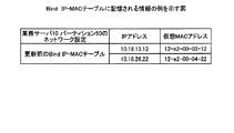
Bind IP−MACテーブル70bは、パーティション内のオペレーティングシステムが参照するアドレス情報を記憶するテーブルである。つまり、オペレーティングシステムは、このテーブルに記憶されるアドレス情報を用いて、データの送受信を実行する。 The Bind IP-MAC table 70b is a table that stores address information referred to by the operating system in the partition. That is, the operating system executes data transmission / reception using the address information stored in the table.
図9は、Bind IP−MACテーブルに記憶される情報の例を示す図である。図9では、一例として、業務サーバ10のパーティション50に対応するテーブルを図示したが、Bind IP−MACテーブル70bは、パーティションごとに情報を記憶する。
FIG. 9 is a diagram illustrating an example of information stored in the Bind IP-MAC table. In FIG. 9, as an example, a table corresponding to the
図9に示すように、Bind IP−MACテーブル70bは、業務サーバ10のパーティション50の情報として、「IPアドレス」と「仮想MACアドレス」とを対応付けて記憶する。ここで記憶される「IPアドレス」は、パーティション50のオペレーティングシステムが参照するIPアドレスであり、「仮想MACアドレス」は、パーティション50のオペレーティングシステムが参照する仮想的なMACアドレスである。なお、Bind IP−MACテーブル70bは、これら以外にもWWNを記憶することもできる。
As illustrated in FIG. 9, the Bind IP-MAC table 70 b stores “IP address” and “virtual MAC address” in association with each other as information on the
図9の例では、パーティション50のオペレーティングシステムは、「IPアドレス、仮想MACアドレス」として「10.18.13.12、12-e2-00-03-12」を参照する。これは、パーティション50の演算部70の筐体内通信部71に設定される情報であり、管理用のアドレス情報である。また、パーティション50のオペレーティングシステムは、「IPアドレス、仮想MACアドレス」として「10.18.26.22、12-e2-00-04-22」を参照する。これは、パーティション50のI/O部60に設定される情報であり、業務用のアドレス情報である。
In the example of FIG. 9, the operating system of the
ネットワーク情報テーブル70cは、パーティション50が有するデバイスおよびデバイスが接続されるネットワークに関する情報を記憶するテーブルである。図10は、ネットワーク情報テーブルに記憶される情報の例を示す図である。
The network information table 70c is a table that stores information about the devices included in the
ネットワーク情報テーブル70cは、「Bus/Dev/Func、種別、IPアドレス、仮想MACアドレス、仮想WWN」を対応付けて記憶する。「Bus/Dev/Func」は、デバイスを特定する情報であり、「種別」は、デバイスの種別を示す情報である。「IPアドレス」は、デバイスに設定されているIPアドレスであり、「仮想MACアドレス」は、オペレーティングシステムが当該デバイスのMACアドレスとして認識する仮想的なMACアドレスである。「仮想WWN」は、オペレーティングシステムが当該デバイスのWWNとして認識する仮想的なWWNである。 The network information table 70c stores “Bus / Dev / Func, type, IP address, virtual MAC address, virtual WWN” in association with each other. “Bus / Dev / Func” is information for specifying a device, and “Type” is information indicating the type of device. The “IP address” is an IP address set for the device, and the “virtual MAC address” is a virtual MAC address that the operating system recognizes as the MAC address of the device. “Virtual WWN” is a virtual WWN that the operating system recognizes as the WWN of the device.
図10の例では、ネットワーク情報テーブル70cは、「0/7/0、LAN、10.18.13.12、12-e2-00-03-12、−」、「8/0/0、LAN、10.18.26.22、12-e2-00-04-22、−」、「9/0/0、FC、−、−、10:00:00:a0:98:00:00:22」を記憶する。 In the example of FIG. 10, the network information table 70 c includes “0/7/0, LAN, 10.18.13.12, 12-e2-00-03-12, −”, “8/0/0, LAN, 10.18.26.22”. , 12-e2-00-04-22,-"," 9/0/0, FC,-,-, 10: 00: a0: 98: 00: 00: 22 ".
つまり、デバイス「0/7/0」は、LANに接続されるデバイスであり、IPアドレス「10.18.13.12」と仮想MACアドレス「12-e2-00-03-12」が設定されている。また、デバイス「8/0/0」は、LANに接続されるデバイスであり、IPアドレス「10.18.26.22」と仮想MACアドレス「12-e2-00-04-22」が設定されている。また、デバイス「9/0/0」は、SANに接続されるデバイスであり、WWN「10:00:00:a0:98:00:00:22」が設定されている。 That is, the device “0/7/0” is a device connected to the LAN, and the IP address “10.18.13.12” and the virtual MAC address “12-e2-00-03-12” are set. The device “8/0/0” is a device connected to the LAN, and an IP address “10.18.26.22” and a virtual MAC address “12-e2-00-04-22” are set. The device “9/0/0” is a device connected to the SAN, and the WWN “10: 00: 00: 00 a0: 98: 00: 00: 22” is set.
適用判定部76は、リカバリに伴う管理アドレスの変更適否を判定する処理部である。具体的には、適用判定部76は、リカバリ時に管理アドレスの変更が発生するかを判定し、発生する場合に当該変更の適否を判定する。そして、適用判定部76は、管理アドレスの変更が発生する場合、故障したパーティションに設定される管理アドレスではなく、リカバリ先のパーティションに元々設定された管理アドレスを、リカバリ後に使用することを決定する。
The
ここで、適用判定部76による適用判定について、パーティション50を例にして説明する。図11は、ネットワーク変更の適用可否の判定例を説明する図である。図11に示すように、適用判定部76は、図10に示したネットワーク情報テーブル70cと図8に示した筐体内外情報テーブル70aとから、各デバイスが管理用(筐体内)ネットワークか業務用(筐体外)ネットワークのいずれに接続されるかを判定する(図11の11A)。
Here, application determination by the
ここでは、適用判定部76は、デバイス「0/7/0」については管理用の筐体内ネットワークに接続されるデバイスであると判定する。つまり、デバイス「0/7/0」は、筐体内通信部71に該当する。また、適用判定部76は、デバイス「8/0/0」と「9/0/0」については業務用の筐体外ネットワークに接続されるデバイスであると判定する。つまり、デバイス「8/0/0」は、業務LAN通信部61に該当し、デバイス「9/0/0」は、SAN通信部62に該当する。
Here, the
そして、適用判定部76は、仮想アドレス切替部75から切替対象のネットワーク情報を取得する(図11の11B)。具体的には、適用判定部76は、「Bus/Dev/Func、種別、IPアドレス、仮想MACアドレス、仮想WWN」を対応付けた情報を取得する。ここでは、適用判定部76は、「0/7/0、LAN、10.18.13.11、12-e2-00-03-11、−」、「8/0/0、LAN、10.18.23.11、12-e2-00-04-11、−」、「9/0/0、FC、−、−、10:00:00:a0:98:00:00:11」を取得する。
And the
その後、適用判定部76は、図11の11Aに示すリカバリ先の現在のネットワーク情報と、図11の11Bに示すリカバリ元のネットワーク情報とを比較し、管理用アドレスの変更が発生するかを判定する(図11の11C)。この例では、適用判定部76は、図11の11Aに示す筐体内ネットワークと判定されたデバイス「0/7/0」のアドレスと、図11の11Bにおいてデバイス「0/7/0」に対応するアドレスとが異なっていることから、管理用アドレスの変更が発生すると判定する。
After that, the
この結果、適用判定部76は、リカバリにおいて、筐体内ネットワークで使用する管理アドレスの変更を拒否し、筐体外ネットワークで使用する業務アドレスの変更を許容すると判定する(図11の11D)。
As a result, in the recovery, the
具体的には、適用判定部76は、リカバリにおいて管理アドレスの変更が仮想アドレス切替部75より要求されているが、リカバリ前後で管理アドレスを変更することになり、競合が発生する危険があると判定する。したがって、適用判定部76は、管理アドレスについては、リカバリ元であるパーティション120の管理アドレスを反映しないと判定する。一方、適用判定部76は、リカバリ後はリカバリ元のパーティション120の業務を実行するので、業務アドレスは変更すると判定する。したがって、適用判定部76は、業務アドレスについては、リカバリ元であるパーティション120の業務アドレスを反映すると判定する。
Specifically, the
これらの結果を踏まえて、適用判定部76は、仮想アドレス切替部75に対して、管理アドレスの変更を拒否し、業務アドレスの変更を許容する指示を送信する。また、適用判定部76は、テーブル更新部77に対して、反映対象の業務アドレスを送信して、Bind IP−MACテーブル70bの更新を指示する。ここでは、適用判定部76は、「8/0/0、LAN、10.18.23.11、12-e2-00-04-11、−」をテーブル更新部77に送信する。その後、仮想アドレス切替部75は、管理アドレスの再設定を抑制し、業務アドレスとWWNの設定を実行する。
Based on these results, the
テーブル更新部77は、リカバリにともなって、Bind IP−MACテーブル70bの更新を実行する処理部である。具体的には、テーブル更新部77は、適用判定部76から受信した「8/0/0、LAN、10.18.23.11、12-e2-00-04-11、−」をBind IP−MACテーブル70bに追加する。
The
図12は、Bind IP−MACテーブルの更新例を説明する図である。図12に示すように、テーブル更新部77は、「IPアドレス、仮想MACアドレス」として「10.18.13.12、12-e2-00-03-12」と「10.18.26.22、12-e2-00-04-22」が記憶される状況で、「10.18.23.11、12-e2-00-04-11」を受信する。すると、テーブル更新部77は、Bind IP−MACテーブル70bに、「10.18.23.11、12-e2-00-04-11」に対応する新たなレコードを追加する。この結果、パーティション50のオペレーティングシステムは、リカバリ後に、リカバリされたパーティション120の業務アドレスを正確に認識することができ、通信断を発生させずに業務に関する通信等を実行できる。
FIG. 12 is a diagram illustrating an example of updating the Bind IP-MAC table. As shown in FIG. 12, the
[処理の流れ]
図13は、実施例2に係るシステムが実行する処理の流れを示すフローチャートである。図13に示すように、サーバ管理部180がパーティション120の故障を検出すると(S201:Yes)、パーティション120は、パーティション120すなわち業務サーバを停止する(S202)。
[Process flow]
FIG. 13 is a flowchart illustrating a flow of processing executed by the system according to the second embodiment. As shown in FIG. 13, when the
続いて、故障したパーティション120が、サーバ管理部180に対してネットワークの切替を指示し、サーバ管理部180が、ネットワークをリカバリ先に切り替える(S203)。このとき、サーバ管理部180は、リカバリ要求をサーバ管理部80に送信する。
Subsequently, the failed
そして、サーバ管理部80のリカバリ実行部87が、サーバ環境情報テーブル82に従って、設定対象である管理アドレス等のサーバ環境をリカバリ先のパーティション50に通知し、仮想アドレス切替部75が、各アドレス等を仮設定する(S204)。続いて、サーバ管理部80のリカバリ実行部87は、リカバリ対象のサーバ環境が設定された待機系サーバを起動させる(S205)。一例としては、リカバリ実行部87は、待機系サーバにリカバリ対象のサーバ環境が設定した後、当該待機系サーバを再起動させる。
Then, the
その後、リカバリ先のパーティション50の適用判定部76は、筐体内ネットワークすなわち管理アドレスの変更があるかを判定する(S206)。
Thereafter, the
ここで、適用判定部76は、変更がないと判定した場合(S207:No)、リカバリ元の管理アドレスをそのまま設定することを許容する(S208)。つまり、仮想アドレス切替部75は、S204で仮設定した状態を適用し、正式に設定を完了する。
Here, when it is determined that there is no change (S207: No), the
一方、適用判定部76は、変更があると判定した場合(S207:Yes)、筐体内ネットワークの変更を取り消す(S209)。つまり、適用判定部76は、仮想アドレス切替部75に対して、仮設定した管理アドレスの再設定を指示する。
On the other hand, if it is determined that there is a change (S207: Yes), the
そして、仮想アドレス切替部75は、S204で仮設定したリカバリ元であるパーティション120の管理アドレスを破棄し、リカバリ先であるパーティション50に元々設定されていた管理アドレスを再設定する(S210)。
Then, the virtual
S208またはS210を処理した後、仮想アドレス切替部75は、設定対象である業務アドレス等のサーバ環境をリカバリ先のパーティション50に設定する(S211)。そして、テーブル更新部77は、パーティション50に設定されたサーバ環境を有効にするために、設定されたサーバ環境でBind IP−MACテーブル70bを更新する(S212)。
After processing S208 or S210, the virtual
[効果]
このように、サーバ管理部80は、リカバリ先のパーティションが動作中であっても、リカバリ元のパーティションを正確にリカバリすることができる。したがって、停止中の待機系を用意しなくても、運用しているパーティションでリカバリすることができるので、効率的なサーバ運用を実現できる。また、リカバリ先のパーティションは、単純にアドレス情報を設定するだけでなく、オペレーティングシステムが参照できるようにBind IP−MACテーブル70bを更新することもできる。このため、リカバリ完了後に設定ミス等による通信断の発生を抑制できる。
[effect]
As described above, the
さて、これまで本発明の実施例について説明したが、本発明は上述した実施例以外にも、種々の異なる形態にて実施されてよいものである。そこで、以下に異なる実施例を説明する。 Although the embodiments of the present invention have been described so far, the present invention may be implemented in various different forms other than the embodiments described above. Therefore, different embodiments will be described below.
(リカバリ対象)
上記実施例では、パーティション120をパーティション50でリカバリする例を説明したが、リカバリ対象をパーティションに限定するものではない。例えば、物理サーバをパーティションでリカバリすることもでき、パーティションを物理サーバでリカバリすることもでき、仮想マシン等を用いてリカバリすることもできる。
(Target for recovery)
In the above embodiment, the example in which the
(システム)
また、本実施例において説明した各処理のうち、自動的におこなわれるものとして説明した処理の全部または一部を手動的におこなうこともできる。あるいは、手動的におこなわれるものとして説明した処理の全部または一部を公知の方法で自動的におこなうこともできる。この他、上記文書中や図面中で示した処理手順、制御手順、具体的名称、各種のデータやパラメータを含む情報については、特記する場合を除いて任意に変更することができる。
(system)
In addition, among the processes described in the present embodiment, all or a part of the processes described as being automatically performed can be manually performed. Alternatively, all or part of the processing described as being performed manually can be automatically performed by a known method. In addition, the processing procedure, control procedure, specific name, and information including various data and parameters shown in the above-described document and drawings can be arbitrarily changed unless otherwise specified.
また、図示した各装置の各構成要素は機能概念的なものであり、必ずしも物理的に図示の如く構成されていることを要しない。すなわち、各装置の分散や統合の具体的形態は図示のものに限られない。つまり、その全部または一部を、各種の負荷や使用状況などに応じて、任意の単位で機能的または物理的に分散・統合して構成することができる。さらに、各装置にて行なわれる各処理機能は、その全部または任意の一部が、CPUおよび当該CPUにて解析実行されるプログラムにて実現され、あるいは、ワイヤードロジックによるハードウェアとして実現され得る。 Further, each component of each illustrated apparatus is functionally conceptual, and does not necessarily need to be physically configured as illustrated. That is, the specific form of distribution and integration of each device is not limited to the illustrated one. That is, all or a part of them can be configured to be functionally or physically distributed / integrated in arbitrary units according to various loads or usage conditions. Further, all or any part of each processing function performed in each device may be realized by a CPU and a program analyzed and executed by the CPU, or may be realized as hardware by wired logic.
(業務サーバの構成)
本実施例で開示する業務サーバの構成例を図14に示す。図14は、業務サーバのハードウェア構成例を説明する図である。図14に示すように、各業務サーバは、バックプレーン100に複数の切換装置としてのクロスバとしてXB101、XB102などを有し、クロスバそれぞれにシステムボードとしてSB110〜SB113と入出力システムボードとしてIOSB150とを有する。なお、クロスバ、システムボード、入出力システムボードの数はあくまで例示であり、これに限定されるものではない。
(Business server configuration)
A configuration example of the business server disclosed in this embodiment is shown in FIG. FIG. 14 is a diagram illustrating a hardware configuration example of a business server. As shown in FIG. 14, each business server has XB101, XB102, etc. as crossbars as a plurality of switching devices on the
バックプレーン100は、複数のコネクタ等を相互接続するバスを形成する回路基板である。XB101、XB102は、システムボードと入出力システムボードとの間でやり取りされるデータの経路を動的に選択するスイッチである。
The
また、XB101に接続されるSB110、SB111、SB112、SB113は、電子機器を構成する電子回路基板であり同様の構成を有するので、ここではSB110についてのみ説明する。なお、各SBは、例えば各パーティションやサーバ管理部に該当する。また、SB110は、システムコントローラ(System Controller:SC)110aと、4台のCPU110b〜110eと、メモリアクセスコントローラ(Memory Access Controller:MAC)110hおよび110iと、DIMM(Dual Inline Memory Module)110fおよび110gとを有する。
In addition, since SB110, SB111, SB112, and SB113 connected to XB101 are electronic circuit boards constituting the electronic device and have the same configuration, only SB110 will be described here. Each SB corresponds to, for example, each partition or server management unit. The
SC110aは、SB110に搭載されるCPU110b〜110eとMAC110h、MAC110iとの間におけるデータ転送などの処理を制御し、SB110全体を制御する。
The
CPU110b〜110eそれぞれは、SC110aを介して他のLSIと接続され、本実施の形態で開示したリカバリ制御方法を実現するプロセッサである。例えば、各CPUは、演算部やサーバ管理部等で実行される各種処理を実行する。
Each of the
MAC110hは、DIMM110fとSC110aとの間に接続され、DIMM110fへのアクセスを制御する。MAC110iは、DIMM110gとSC110aとの間に接続され、DIMM110gへのアクセスを制御する。DIMM110fは、SC110aを介して他の電子機器と接続され、メモリを装着してメモリ増設などを行うメモリモジュールである。DIMM110gは、SC110aを介して他の電子機器と接続され、メモリを装着してメモリ増設などを行う主記憶装置(メインメモリ)としてのメモリモジュールである。
The
IOSB150は、XB101を介してSB110〜SB113それぞれと接続されるとともに、SCSI(Small Computer System Interface)、FC(Fibre Channel)、イーサネット(登録商標)などを介して入出力デバイスと接続される。IOSB150は、入出力デバイスとXB101との間におけるデータ転送などの処理を制御する。なお、SB110に搭載されるCPU、MAC、DIMMなどの電子機器はあくまで例示であり、電子機器の種類又は電子機器の数が図示したものに限定されるものではない。
The
10、110 業務サーバ
20、50、120、150 パーティション
30、60、130、160 I/O部
31、61 業務LAN通信部
32、62 SAN通信部
40、70、140、170 演算部
70a 筐体内外情報テーブル
70b Bind IP−MACテーブル
70c ネットワーク情報テーブル
41、71 筐体内通信部
42、72 故障検出部
43、73 サーバ停止部
44、74 NW切替依頼部
45、75 仮想アドレス切替部
76 適用判定部
77 テーブル更新部
80、180 サーバ管理部
81 通信制御部
82 サーバ環境情報テーブル
83 送受信部
84 検出部
85 調整部
86 監視部
87 リカバリ実行部
10, 110
Claims (7)
第1の管理ネットワークを介して監視される、前記情報処理装置としての機能を発揮する第1の処理機能部で、第2の管理ネットワークを介して監視される第2の処理機能部をリカバリさせる場合、前記記憶部を参照して、前記第2の処理機能部が筐体内ネットワークで使用する筐体内アドレス情報の変更が発生するか否かを判定する判定部と、
前記筐体内アドレス情報の変更が発生する場合、筐体内アドレス情報の変更を抑制するとともに筐体外ネットワークで使用される筐体外アドレス情報の変更を適用すると判定し、前記第1の処理機能部に対応する筐体内アドレス情報と前記第2の処理機能部に対応する筐体外アドレス情報とを設定して、前記第2の処理機能部を前記第1の処理機能部でリカバリするリカバリ実行部と
を有することを特徴とする情報処理装置。 For each processing function unit that performs a function as an information processing apparatus, address information assigned to each device used by the processing function unit, and a network indicating whether the network to which each device is connected is an intra-casing network or an external network A storage unit for storing information in association with each other;
It is monitored via a first management network, by the first processing function unit to function as the information processing apparatus, to recover the second processing function unit to be monitored via a second management network A determination unit that refers to the storage unit and determines whether or not a change in in-housing address information used by the second processing function unit in the in-housing network occurs ;
When the change of the address information in the case occurs, it is determined that the change of the address information in the case is suppressed and the change of the address information outside the case used in the network outside the case is applied, and corresponds to the first processing function unit A recovery execution unit configured to set address information inside the case to be performed and address information outside the case corresponding to the second processing function unit, and recover the second processing function unit by the first processing function unit. An information processing apparatus characterized by that.
前記第2の処理機能部は、前記第1のサーバ装置とは異なる第2のサーバ装置が有するパーティションであることを特徴とする請求項1に記載の情報処理装置。 The first processing function unit is a partition that the first server device has,
The information processing apparatus according to claim 1, wherein the second processing function unit is a partition included in a second server apparatus different from the first server apparatus.
前記リカバリ実行部は、前記第2の処理機能部のリカバリが発生する前に、前記第1の処理機能部の筐体内アドレス情報と前記第2の処理機能部の筐体外アドレス情報とを、前記第1の処理機能部に事前に設定しておくことを特徴とする請求項1に記載の情報処理装置。The recovery execution unit obtains the in-housing address information of the first processing function unit and the out-of-housing address information of the second processing function unit before the recovery of the second processing function unit occurs. The information processing apparatus according to claim 1, wherein the information processing apparatus is set in advance in the first processing function unit.
情報処理装置としての機能を発揮する処理機能部ごとに、当該処理機能部が使用する各デバイスに割当てられるアドレス情報と、各デバイスが接続されるネットワークが筐体内ネットワークか筐体外ネットワークかを示すネットワーク情報とを対応付けて記憶する記憶部を参照し、
第1の管理ネットワークを介して監視される、前記情報処理装置としての機能を発揮する第1の処理機能部で、第2の管理ネットワークを介して監視される第2の処理機能部をリカバリさせる場合、前記第2の処理機能部が筐体内ネットワークで使用する筐体内アドレス情報の変更が発生するか否かを判定し、
前記筐体内アドレス情報の変更が発生する場合、筐体内アドレス情報の変更を抑制するとともに筐体外ネットワークで使用される筐体外アドレス情報の変更を適用すると判定し、前記第1の処理機能部に対応する筐体内アドレス情報と前記第2の処理機能部に対応する筐体外アドレス情報とを設定して、前記第2の処理機能部を前記第1の処理機能部でリカバリする
処理を含んだことを特徴とするリカバリ管理方法。 Information processing device
For each processing function unit that performs a function as an information processing apparatus, address information assigned to each device used by the processing function unit, and a network indicating whether the network to which each device is connected is an intra-casing network or an external network Refer to the storage unit that stores information in association with each other,
It is monitored via a first management network, by the first processing function unit to function as the information processing apparatus, to recover the second processing function unit to be monitored via a second management network The second processing function unit determines whether or not a change in address information within the housing used in the network within the housing occurs ,
When the change of the address information in the case occurs, it is determined that the change of the address information in the case is suppressed and the change of the address information outside the case used in the network outside the case is applied, and corresponds to the first processing function unit A process for setting the address information in the casing and the address information outside the casing corresponding to the second processing function unit, and recovering the second processing function unit by the first processing function unit. A featured recovery management method.
前記リカバリする処理は、前記第2の処理機能部のリカバリが発生する前に、前記第1の処理機能部の筐体内アドレス情報と前記第2の処理機能部の筐体外アドレス情報とを、前記第1の処理機能部に事前に設定しておくことを特徴とする請求項6に記載のリカバリ管理方法。The process to recover includes the in-housing address information of the first processing function unit and the out-of-housing address information of the second processing function unit before the recovery of the second processing function unit occurs. The recovery management method according to claim 6, wherein the recovery processing method is set in advance in the first processing function unit.
Priority Applications (2)
| Application Number | Priority Date | Filing Date | Title |
|---|---|---|---|
| JP2013249632A JP6217358B2 (en) | 2013-12-02 | 2013-12-02 | Information processing apparatus and recovery management method |
| US14/549,998 US20150154083A1 (en) | 2013-12-02 | 2014-11-21 | Information processing device and recovery management method |
Applications Claiming Priority (1)
| Application Number | Priority Date | Filing Date | Title |
|---|---|---|---|
| JP2013249632A JP6217358B2 (en) | 2013-12-02 | 2013-12-02 | Information processing apparatus and recovery management method |
Publications (2)
| Publication Number | Publication Date |
|---|---|
| JP2015106385A JP2015106385A (en) | 2015-06-08 |
| JP6217358B2 true JP6217358B2 (en) | 2017-10-25 |
Family
ID=53265420
Family Applications (1)
| Application Number | Title | Priority Date | Filing Date |
|---|---|---|---|
| JP2013249632A Active JP6217358B2 (en) | 2013-12-02 | 2013-12-02 | Information processing apparatus and recovery management method |
Country Status (2)
| Country | Link |
|---|---|
| US (1) | US20150154083A1 (en) |
| JP (1) | JP6217358B2 (en) |
Families Citing this family (1)
| Publication number | Priority date | Publication date | Assignee | Title |
|---|---|---|---|---|
| KR102374767B1 (en) * | 2020-09-29 | 2022-03-14 | 엘에스일렉트릭(주) | System for copying inverter setting based on web and device thereof |
Family Cites Families (8)
| Publication number | Priority date | Publication date | Assignee | Title |
|---|---|---|---|---|
| JP3441264B2 (en) * | 1995-09-26 | 2003-08-25 | 三菱電機株式会社 | Multi-system |
| US7499410B2 (en) * | 2001-12-26 | 2009-03-03 | Cisco Technology, Inc. | Fibre channel switch that enables end devices in different fabrics to communicate with one another while retaining their unique fibre channel domain—IDs |
| JP4757670B2 (en) * | 2006-03-16 | 2011-08-24 | 株式会社日立製作所 | System switching method, computer system and program thereof |
| JP4279298B2 (en) * | 2006-07-18 | 2009-06-17 | 株式会社東芝 | Computer system and program capable of taking over service and IP address |
| US8108514B2 (en) * | 2008-04-02 | 2012-01-31 | International Business Machines Corporation | High availability of internet protocol addresses within a cluster |
| JP4811489B2 (en) * | 2009-03-27 | 2011-11-09 | 日本電気株式会社 | Server system, collective server device, and MAC address management method |
| JP5594668B2 (en) * | 2010-10-21 | 2014-09-24 | データアクセス株式会社 | Node, clustering system, clustering system control method, and program |
| US9923787B2 (en) * | 2012-04-27 | 2018-03-20 | International Business Machines Corporation | Network configuration predictive analytics engine |
-
2013
- 2013-12-02 JP JP2013249632A patent/JP6217358B2/en active Active
-
2014
- 2014-11-21 US US14/549,998 patent/US20150154083A1/en not_active Abandoned
Also Published As
| Publication number | Publication date |
|---|---|
| JP2015106385A (en) | 2015-06-08 |
| US20150154083A1 (en) | 2015-06-04 |
Similar Documents
| Publication | Publication Date | Title |
|---|---|---|
| US10432470B2 (en) | Distributed subnet manager for InfiniBand networks | |
| CN105743692B (en) | Policy-based framework for application management | |
| Yamato et al. | Fast and reliable restoration method of virtual resources on OpenStack | |
| US9582377B1 (en) | Dynamic sizing of storage capacity for a remirror buffer | |
| US11226753B2 (en) | Adaptive namespaces for multipath redundancy in cluster based computing systems | |
| US9237093B2 (en) | Bandwidth on-demand adaptive routing | |
| US20200073656A1 (en) | Method and Apparatus for Drift Management in Clustered Environments | |
| GB2492620A (en) | Midplane for blade server management | |
| JP2007172334A (en) | Method, system and program for securing redundancy of parallel computing system | |
| CN106980529B (en) | Computer system for managing resources of baseboard management controller | |
| JP2014522052A (en) | Reduce hardware failure | |
| WO2018137520A1 (en) | Service recovery method and apparatus | |
| US11349706B2 (en) | Two-channel-based high-availability | |
| CN107645402B (en) | Route management method and device | |
| US20190334990A1 (en) | Distributed State Machine for High Availability of Non-Volatile Memory in Cluster Based Computing Systems | |
| US20210075763A1 (en) | System and method of using a global discovery service to enable routing of packets from a source container to a destination container | |
| BR112017011541B1 (en) | METHOD FOR PROCESSING A BLOCK REQUEST, BLOCK REQUEST MANAGEMENT APPARATUS AND SERVER | |
| CN113656147A (en) | Cluster deployment method, device, equipment and storage medium | |
| JP5531487B2 (en) | Server system and server system management method | |
| WO2021072130A1 (en) | Dynamic discovery of service nodes in a network | |
| US9430341B2 (en) | Failover in a data center that includes a multi-density server | |
| Venâncio et al. | VNF‐Consensus: A virtual network function for maintaining a consistent distributed software‐defined network control plane | |
| JP6217358B2 (en) | Information processing apparatus and recovery management method | |
| US10305987B2 (en) | Method to syncrhonize VSAN node status in VSAN cluster | |
| US8929251B2 (en) | Selecting a master processor from an ambiguous peer group |
Legal Events
| Date | Code | Title | Description |
|---|---|---|---|
| A621 | Written request for application examination |
Free format text: JAPANESE INTERMEDIATE CODE: A621 Effective date: 20160804 |
|
| A977 | Report on retrieval |
Free format text: JAPANESE INTERMEDIATE CODE: A971007 Effective date: 20170412 |
|
| A131 | Notification of reasons for refusal |
Free format text: JAPANESE INTERMEDIATE CODE: A131 Effective date: 20170418 |
|
| A521 | Request for written amendment filed |
Free format text: JAPANESE INTERMEDIATE CODE: A523 Effective date: 20170614 |
|
| TRDD | Decision of grant or rejection written | ||
| A01 | Written decision to grant a patent or to grant a registration (utility model) |
Free format text: JAPANESE INTERMEDIATE CODE: A01 Effective date: 20170829 |
|
| A61 | First payment of annual fees (during grant procedure) |
Free format text: JAPANESE INTERMEDIATE CODE: A61 Effective date: 20170911 |
|
| R150 | Certificate of patent or registration of utility model |
Ref document number: 6217358 Country of ref document: JP Free format text: JAPANESE INTERMEDIATE CODE: R150 |