JP6216552B2 - Vibration suppression suspension structure - Google Patents
Vibration suppression suspension structure Download PDFInfo
- Publication number
- JP6216552B2 JP6216552B2 JP2013132907A JP2013132907A JP6216552B2 JP 6216552 B2 JP6216552 B2 JP 6216552B2 JP 2013132907 A JP2013132907 A JP 2013132907A JP 2013132907 A JP2013132907 A JP 2013132907A JP 6216552 B2 JP6216552 B2 JP 6216552B2
- Authority
- JP
- Japan
- Prior art keywords
- suspension
- connecting member
- suspension rod
- vibration
- swing
- Prior art date
- Legal status (The legal status is an assumption and is not a legal conclusion. Google has not performed a legal analysis and makes no representation as to the accuracy of the status listed.)
- Active
Links
Images


Landscapes
- Vibration Prevention Devices (AREA)
Description
この発明は、支持体に吊ロッドを介して吊り下げられた被吊下物の振動を抑制する振動抑制吊構造に関するものである。 The present invention relates to a vibration suppressing suspension structure that suppresses vibration of a suspended object suspended from a support via a suspension rod.
従来、天井スラブに吊ボルトで吊り下げられた吊設備機器が、大地震等により落下することがあった。原因を検討すると、吊ボルトの根元(基端部、天井スラブに固定される上端部)に応力が集中し、該根元の降伏後に塑性変形が累積して吊ボルトの根元が破断に至ることがわかった。このような吊ボルトの破断を防止するために、一対の吊ボルトの一方の根元と他方の先端部(吊設備機器に固定される下端部)との間に筋交いを設け、各吊ボルトの変形を抑えたものがある(例えば、特許文献1参照)。 Conventionally, a suspension equipment device suspended from a ceiling slab with a suspension bolt may fall due to a large earthquake or the like. When the cause is examined, stress concentrates on the base of the suspension bolt (base end, upper end fixed to the ceiling slab), and plastic deformation accumulates after the base yields, and the base of the suspension bolt may break. all right. In order to prevent such breakage of the suspension bolt, a brace is provided between one base of the pair of suspension bolts and the other end portion (lower end portion fixed to the suspension equipment), and deformation of each suspension bolt (For example, refer to Patent Document 1).
しかし、上述のような吊構造においては、吊ボルト等の吊り下げ用のロッド部材(以下、「吊ロッド」と呼ぶ。)とともに筋交いを設けることにより、吊ロッドの変形を飛躍的に抑えることができるが、筋交いが隣接する一方の吊ロッドの基端部と他方の吊ロッドの先端部とを連結する部材であるため、例えば、隣接する吊ロッドの間に梁等の障害物があるときには、筋交いを設けることが困難な場合がある。 However, in the suspension structure as described above, by providing a bracing together with a rod member for suspension such as a suspension bolt (hereinafter referred to as “suspending rod”), the deformation of the suspension rod can be remarkably suppressed. However, since the brace is a member that connects the proximal end of one hanging rod and the distal end of the other hanging rod adjacent to each other, for example, when there is an obstacle such as a beam between the adjacent hanging rods, It may be difficult to provide braces.
そこでこの発明は、隣接する吊ロッド間に筋交いを設けることなく、被吊下物の振動を確実に抑制できるようにして、設置の自由度を高めることのできる振動抑制吊構造を提供しようとするものである。 In view of this, the present invention intends to provide a vibration suppressing suspension structure that can reliably suppress the vibration of the suspended object without providing a bracing between adjacent hanging rods and can increase the degree of freedom of installation. Is.
この発明に係る振動抑制吊構造では、上記課題を解決するために、支持体に複数の吊ロッドで吊り下げられた被吊下物の振動を抑制する振動抑制吊構造において、下端に前記被吊下物が取り付けられる前記複数の吊ロッドと、前記複数の吊ロッドの各上部を前記支持体に連結する複数の連結具と、前記複数の吊ロッドの過大な揺動変位を規制する揺動規制具と、を備え、前記連結具は、前記支持体に対する前記吊ロッドの上部の揺動方向及び上下方向の相対変位を許容する変位許容部と、前記吊ロッドの下方荷重を支持する座と、前記吊ロッドの上部の相対変位時に、その相対変位に伴う運動エネルギーを減衰するエネルギー吸収部と、を備え、前記揺動規制具は、前記複数の吊ロッドの各外周部を取り囲む複数の規制筒と、前記複数の規制筒同士を剛的に連結する連結壁と、を備えている構成とした。 In the vibration suppression suspension structure according to the present invention, in order to solve the above-described problem, in the vibration suppression suspension structure that suppresses the vibration of the suspended object suspended by a plurality of suspension rods on the support body, The plurality of suspension rods to which a lower article is attached, the plurality of coupling members for coupling the upper portions of the plurality of suspension rods to the support, and the swing regulation for restricting excessive swing displacement of the plurality of suspension rods A displacement permitting portion that allows relative displacement in the swinging direction and vertical direction of the upper portion of the suspension rod with respect to the support, and a seat that supports a downward load of the suspension rod; An energy absorbing portion that attenuates kinetic energy associated with the relative displacement of the upper portion of the suspension rod, and the swing restricting tool surrounds the outer peripheral portions of the suspension rods. And the plurality of regulations A connecting wall rigidly connected to each other, has a configuration that includes a.
この構成により、地震等によって被吊下物が振動したときには、各吊ロッドの上部が支持体に対して連結具の変位許容部を介して相対変位し、その相対変位に伴う運動エネルギーが連結具のエネルギー吸収部によって減衰される。これにより、被吊下物の振動エネルギーの一部がエネルギー吸収部によって吸収される。また、被吊下物の振動時には、各吊ロッドの下方荷重は、連結具の座を介して支持体に支持されるものの、各吊ロッドの上部の相対変位は連結具の変位許容部によって許容されるため、各吊ロッドの上端部には大きな応力が集中しなくなる。
また、被吊下物の振動時に吊ロッドの揺動が大きくなると、吊ロッド、若しくは、その吊ロッドの周囲を覆う部材が揺動規制具の規制筒と当接することにより、その揺動が抑制される。つまり、各規制筒は、連結壁によって相互に剛的に連結されているために、吊ロッドの揺動には追従せず、吊ロッド、若しくは、その吊ロッドの周囲を覆う部材と当接して当該吊ロッドの揺動を規制することになる。そして、揺動規制具は、複数の吊ロッドの各外周部を取り囲む複数の規制筒と、その複数の規制筒同士を剛的に連結する連結壁と、を備えた簡単な構造であることから、隣接する吊ロッド間に障害物が存在する場合にも大きなスペースを占有することなく容易に設置することができる。
With this configuration, when the suspended object vibrates due to an earthquake or the like, the upper part of each suspension rod is relatively displaced with respect to the support via the displacement allowable portion of the coupling tool, and the kinetic energy associated with the relative displacement is coupled to the coupling tool. It is attenuated by the energy absorption part. Thereby, a part of vibration energy of the suspended object is absorbed by the energy absorbing portion. In addition, when the suspended object vibrates, the downward load of each suspension rod is supported by the support through the seat of the connector, but the relative displacement of the upper part of each suspension rod is allowed by the displacement allowance portion of the connector. Therefore, a large stress does not concentrate on the upper end portion of each suspension rod.
In addition, if the suspension rod swings greatly during vibration of the suspended object, the suspension rod or a member that covers the periphery of the suspension rod comes into contact with the restriction cylinder of the swing restriction tool, thereby suppressing the swing. Is done. In other words, since each regulating cylinder is rigidly connected to each other by the connecting wall, it does not follow the swinging of the suspension rod, but comes into contact with the suspension rod or a member covering the periphery of the suspension rod. The swinging of the suspension rod is restricted. And since the rocking | fluctuation control tool is a simple structure provided with the some control cylinder which surrounds each outer peripheral part of a some suspension rod, and the connection wall which connects the some control cylinders rigidly. Even when there is an obstacle between adjacent suspension rods, it can be easily installed without occupying a large space.
前記連結壁は、前記規制筒の上下方向の中央よりも下方領域で略水平に延出していることが望ましい。
この場合、複数の規制筒を剛的に連結する連結壁が、規制筒の上下方向の中央よりも下方領域で略水平に延出していることから、吊ロッド間の上方側に梁等の障害物が存在しても、その障害物を避けての設置が可能になる。
The connecting walls, and Turkey not extend substantially horizontally in the lower region than the vertical center of the regulating cylinder is desirable.
In this case, since the connecting wall that rigidly connects the plurality of restriction cylinders extends substantially horizontally in the region below the vertical center of the restriction cylinder, an obstacle such as a beam is formed above the suspension rods. Even if an object exists, it can be installed avoiding the obstacle.
前記規制筒と前記吊ロッドの間には、前記吊ロッドに対する前記規制筒の軸方向の相対変位を規制する規制手段が設けられるようにしても良い。
この場合、被吊下物の振動時に、揺動規制具に上方に突き上げるような荷重が入力されても、規制筒の上方変位は規制手段によって規制されることになる。
Between the regulation cylinder and the suspension rod, a regulation means for regulating relative displacement of the regulation cylinder in the axial direction with respect to the suspension rod may be provided.
In this case, even when a load that pushes upward is input to the swing restricting tool during vibration of the suspended object, the upward displacement of the restricting cylinder is restricted by the restricting means.
前記変位許容部は、前記支持体に取り付けられる第1の連結部材と、前記吊ロッドの上部を吊下げ支持するとともに、前記第1の連結部材に相対変位可能に連結される第2の連結部材と、を備え、前記第1の連結部材と前記第2の連結部材のうちの一方の部材には、他方の部材に揺動可能に摺接する湾曲状のガイド面が設けられ、前記第2の連結部材には、前記吊ロッドの上部が上方変位可能に吊り下げ支持され、前記吊ロッドの上部の被支持部と前記第2の連結部材上の支持部の間には、前記エネルギー吸収部である第1の弾性部材が設けられ、前記第1の連結部材と前記第2の連結部材の間には、前記エネルギー吸収部である第2の弾性部材が介装されるようにしても良い。
この場合、被吊下物の下方荷重が吊ロッドに入力されると、その荷重は第1の弾性部材を介して吊ロッドの上部から第2の連結部材に入力される。第2の連結部材に入力された荷重は、ガイド面を介して第1の連結部材に入力され、第1の連結部材を介して支持体に支持される。また、被吊下物の振動時に、吊ロッドが上下方向に振動すると、その振動は吊ロッドと第2の連結部材の間の第1の弾性部材と、第1の連結部材と第2の連結部材の間の第2の弾性部材とによって減衰される。また、被吊下物の振動時に、連結具内のガイド面を支持部として吊ロッドの上部が揺動すると、その振動は第2の弾性部材によって減衰される。
The displacement allowing portion includes a first connecting member attached to the support and a second connecting member that supports the upper portion of the suspension rod in a suspended manner and is connected to the first connecting member so as to be relatively displaceable. One of the first connecting member and the second connecting member is provided with a curved guide surface that slidably contacts the other member, and the second connecting member is provided with the second connecting member. The upper part of the suspension rod is supported by the connection member so as to be displaceable upward, and the energy absorbing unit is interposed between the supported part on the upper part of the suspension rod and the support part on the second connection member. A first elastic member may be provided, and a second elastic member that is the energy absorbing portion may be interposed between the first connecting member and the second connecting member.
In this case, when the downward load of the suspended object is input to the suspension rod, the load is input to the second connecting member from the upper portion of the suspension rod via the first elastic member. The load input to the second connecting member is input to the first connecting member via the guide surface, and is supported by the support via the first connecting member. Further, when the suspension rod vibrates in the vertical direction during the vibration of the suspended object, the vibration is caused by the first elastic member between the suspension rod and the second coupling member, the first coupling member, and the second coupling. Damped by the second elastic member between the members. Further, when the suspended object is vibrated, if the upper part of the hanging rod swings with the guide surface in the connector as a support portion, the vibration is attenuated by the second elastic member.
この発明によれば、隣接する吊ロッド間に筋交いを設けることなく、被吊下物の振動を確実に抑制することができる。このため、被吊下物の設置の自由度を高めることができる。
特に、この発明においては、複数の吊ロッドの各外周部を取り囲む複数の規制筒と、その複数の規制筒同士を剛的に連結する連結壁と、を備えた揺動規制具が設けられているため、被吊下物の振動時に吊ロッドの揺動を速やかに収束させることができる。そして、この発明の場合、連結具に入力される吊ロッドの過大な揺動荷重を揺動規制具に分散させて受け止めることができるため、連結具に作用する負荷を低減することができる。
According to this invention, it is possible to reliably suppress the vibration of the suspended object without providing a bracing between adjacent hanging rods. For this reason, the freedom degree of installation of a suspended object can be raised.
In particular, in the present invention, there is provided a swing restricting tool including a plurality of restricting cylinders that surround the outer peripheral portions of the plurality of suspension rods, and a connection wall that rigidly connects the restricting cylinders. Therefore, the swinging of the suspension rod can be quickly converged when the suspended object vibrates. And in the case of this invention, since the excessive rocking | fluctuation load of the suspension rod input into a coupling tool can be disperse | distributed to a rocking | fluctuation control tool, the load which acts on a coupling tool can be reduced.
以下、この発明の実施形態を図面に基づいて説明する。 Embodiments of the present invention will be described below with reference to the drawings.
<第1の実施形態>
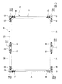
図1〜図3に示すように、この実施形態の振動抑制吊構造1は、支持体の一形態である建造物の天井スラブ2に、被吊下物の一形態である空調設備等の吊設備機器7を吊下げ支持するものであり、地震発生時等における吊設備機器7の振動を抑制する機能を備えている。
吊設備機器7は、例えば長方体状をなし、その上面8を略水平にして天井スラブ2の下方に設置される。吊設備機器7の上面8の側方には、略水平な外向きのフランジ9が設けられている。吊設備機器7の平面視(上面視)の四隅と、長尺な二辺の中途部の各一箇所(計6箇所)には、吊ロッドの一形態である吊ボルト5の下端が固定されている。吊ボルト5は、軸方向の全域の外周面にねじ山が形成されており、その下端が吊設備機器7のフランジ9を貫通した状態で当該フランジ9に締結固定されている。なお、図1中符号4は、天井スラブ2の下面3よりも下方に突出するように建造物に設置された梁である。
<First Embodiment>
As shown in FIG. 1 to FIG. 3, the vibration suppression suspension structure 1 of this embodiment is suspended from a
The
下端が吊設備機器7に固定された各吊ボルト5の上端部は、連結具15を介して天井スラブ2の下面3に連結されている。
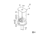
図4〜図6に示すように、連結具15は、アンカーボルト13とナット13aを介して天井スラブ2に固定される第1の連結部材16と、吊ボルト5の上部を支持するとともに、第1の連結部材16に揺動、及び、上下動可能に連結される第2の連結部材17と、吊ボルト5の上部が第1の連結部材16に対して相対変位するときに、その相対変位に伴う運動エネルギーを減衰するエネルギー吸収部である第1の弾性部材28及び第2の弾性部材19と、を備えている。この実施形態においては、第1の連結部材16と第2の連結部材17が支持体(天井スラブ2)に対する吊ボルト5の相対変位を許容する変位許容部を構成している。
An upper end portion of each
As shown in FIGS. 4 to 6, the
第1の連結部材16は、複数の鋼材を溶接や締結具等により一体に結合してなる。第1の連結部材16は、略水平に配置されてアンカーボルト13が貫通する平板状の上端板部21と、上端板部21の水平方向両側から下方に延びる一対の立板部23と、一対の立板部23の下方に連なる下部円筒部23aと、下部円筒部23aの下端に略水平に配置される円板状の係合板部24と、を有する。以下、一対の立板部23にわたる方向を第1の連結部材16の長手方向ということがある。
The first connecting
第1の連結部材16の上端板部21は、係合板部24と略同径の円板に対し、前記長手方向と直交する方向の両側を前記長手方向に沿って切り欠いた形状とされている。上端板部21の略中央位置には、アンカーボルト13が挿通されるボルト孔21aが形成され、係合板部24には、上端板部21のボルト孔21aと同軸位置にそのボルト孔21aよりも大径の円形状の挿通孔24aが形成されている。また、一対の立板部23は、下部円筒部23aを上方に延長させた仮想円筒から、前記長手方向と直交する方向の両側を切り欠いた形状とされている。
The upper
第2の連結部材17は、内側に吊ボルト5の上部が挿通される円筒状の内周壁部34と、内周壁部34の外側に内周壁部34と同軸に配置される外周壁部33と、下方に凸に椀状に湾曲して外周壁部33と内周壁部34の下端部同士を連結するガイド壁部31と、を備えている。第2の連結部材17は、第1の連結部材16の下部円筒部23a内に配置され、ガイド壁部31の湾曲した下面が、第1の連結部材16の挿通孔24aの上面側の縁部に摺動自在に当接するようになっている。この実施形態では、ガイド壁部31の湾曲した下面が、第1の連結部材16に揺動可能に摺接するガイド面40を構成している。
第2の連結部材17の内周壁部34の上部には、後に詳述するように吊ボルト5の上端部が吊り下げ支持されるようになっている。このため、吊ボルト5に作用する吊設備機器7の荷重は、第2の連結部材17のガイド面40と第1の連結部材16の係合板部24(挿通孔24aの上面側の縁部)との当接部を介して第1の連結部材16に入力され、その入力された荷重がアンカーボルト13を介して天井スラブ2に支持される。
The second connecting
As will be described in detail later, the upper end portion of the
また、第2の連結部材17の内周壁部34の下縁には、吊ボルト5の外側を隙間をもって囲繞する金属製の補強パイプ42の上端部が固定されている。補強パイプ42は、吊ボルト5の外周側に配置されて吊ボルト5の曲げ強度を補う部材であり、その下端は後に詳述するように吊ボルト5の下端近傍に支持されている。なお、挿通孔24aは、連結具15(第1の連結部材16)に対する吊ボルト5と補強パイプ42の揺動を許容するように補強パイプ42の外径よりも大きい内径とされている。
Further, an upper end portion of a
内周壁部34を貫通した吊ボルト5の上端部には、円環状の第1の弾性部材28が一対のワッシャ29によって上下を挟み込まれた状態で嵌装されるとともに、第1の弾性部材28とワッシャ29の上方変位を規制する(抜け止めする)ためのナット27が取り付けられている。ナット27によって変位規制された下方のワッシャ29は、内周壁部34の上端面に当接している。吊ボルト5に作用する下方荷重(吊設備機器7の垂直荷重)は、ナット27と第1の弾性部材28を介して内周壁部34に作用する。このため、吊設備機器7から吊ボルト5に入力された上下方向の振動成分は第1の弾性部材28によって減衰される。
なお、この実施形態では、ナット27が吊ボルト5の上部の被支持部を構成し、内周壁部34の上端面が第2の連結部材17上の支持部を構成している。また、この実施形態では、第2の連結部材17の内周壁部34の上端面や、第1の連結部材16の係合板部24の上面等が吊ボルト5の下方荷重を支持する座を構成している。
An annular first
In this embodiment, the
第1の連結部材16側の下部円筒部23aの内周面と、第2の連結部材17側の外周壁部33の外周面との間には、円筒状の第2の弾性部材19が挟み込まれて配置されている。第2の弾性部材19は、吊設備機器7の振動に伴って第2の連結部材17が吊ボルト5の上部とともに揺動方向や上下方向に振動すると、その振動に応じて撓み変形することにより、吊ボルト5の振動を減衰する。
第2の弾性部材19は、第2の連結部材17の外周壁部33の外周面と、第1の連結部材16の下部円筒部23aの内周面に接着等によって固定されている。外周壁部33と下部円筒部23aとの間で第2の弾性部材19が伸縮変形やせん断変形することにより、吊ボルト5の揺動や上下振動を減衰することができる。
A cylindrical second
The second
また、この振動抑制吊構造1においては、図1〜図3に示すように、複数の吊ボルト5の過大な揺動変位を規制する揺動規制具50が設けられている。
揺動規制具50は、複数の吊ボルト5の各外周部を取り囲む複数の規制筒51と、複数の規制筒51同士を剛的に連結する連結壁52と、を備えている。この実施形態の場合、規制筒51と連結壁52は鋼材等の金属材料によって形成されている。規制筒51は、その内径が補強パイプ42の外径よりも所定寸法大きく形成されており、各吊ボルト5と補強パイプ42の外側を所定隙間をもって取り囲むように配置される。
Moreover, in this vibration suppression suspension structure 1, as shown in FIGS. 1-3, the rocking |
The
各規制筒51は、周域を取り囲む補強パイプ42よりも若干短い軸長に形成されている。また、この実施形態の連結壁52は、各規制筒51の下端近傍(上下方向の中央よりも下方領域)の外周に溶接固定される継手材53と、略水平方向に延出して隣接する継手材53同士を接続する梁材54と、を備え、各継手材53と梁材54が接続プレート55を介してボルト締結されている。
図2に示すように、平面視で四隅に配置される継手材53は、規制筒51を挟む略直角な二方にそれぞれ継手片が延出する形状とされ、平面視で長辺の中途部に配置される継手材53は、規制筒51を挟む相反方向の二方にそれぞれ継手片が延出する形状とされている。なお、図面において、平面視で四隅に配置される継手材53には、符号53Aを付し、平面視で長辺の中途部に配置される継手材53には、符号53Bを付してある。
各梁材54は、図7に示すように断面コ状に形成されている。また、継手材53は、各継手片の断面が、梁材54の断面に対応するように略コ字状、若しくは、H状に形成されている。
Each regulating
As shown in FIG. 2, the
Each
この実施形態の場合、各規制筒51の下端近傍の外周に継手材53が溶接され、隣接する継手材53同士が、略水平方向に延出する梁材54を介して相互に連結される構造とされているため、継手材53と梁材54の連結態様を変更することにより、吊設備機器7の形状やサイズに応じて揺動規制具50の形状やサイズを容易に変更することができる。
In the case of this embodiment, the
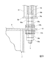
図8,図9に示すように、前述した吊ボルト5の下端は、吊設備機器7のフランジ9を貫通した状態において、吊ボルト5に螺合されるナット56a,56b,56cによって上下から挟み込んで固定されている。なお、フランジ9の下面とナット56bの間と、フランジ9の上面とナット56cの間には、それぞれ防振用の弾性部材57a,57bが介装されている。
As shown in FIGS. 8 and 9, the lower end of the above-described
また、揺動規制具50の各規制筒51の下端には、端部プレート58が一体に取り付けられ、その端部プレート58に吊ボルト5の挿通される貫通孔58aが形成されている。吊ボルト5の下部領域の吊設備機器7との締結部よりも上方位置には、吊ボルト5に螺合されるナット59a,59bによって端部プレート58が上下から挟み込まれることで、規制筒51の下端が固定されている。また、吊ボルト5の外周側に配置される補強パイプ42は、図9に示すように、その下端がナット59bの上面に当接することにより、吊ボルト5に対する下方変位を規制されている。なお、この実施形態においては、規制筒51の下端の端部プレート58を上下から挟み込んで吊ボルト5に固定する一対のナット59a,59bが、吊ボルト5に対する規制筒51の軸方向の相対変位を規制する規制手段を構成している。
Further, an
この振動抑制吊構造1の場合、吊設備機器7の荷重は複数の吊ボルト5と連結具15を介して天井スラブ2に支持されるが、連結具15の内部においては、吊ボルト5に作用する下方荷重が吊ボルト5の上端のナット27と第1の弾性部材28を介して第2の連結部材17の内周壁部34に入力される。そして、第2の連結部材17に入力された下方荷重は、第2の連結部材17のガイド面40と第1の連結部材16の係合板部24との当接部を通して第2の連結部材17に入力され、第2の連結部材17を介して天井スラブ2に支持される。
In the case of this vibration suppression suspension structure 1, the load of the
この状態から地震等により被吊下物である吊設備機器7が振動すると、図10に示すように、複数の吊ボルト5の上部がその振動の上下方向成分を受けて連結具15内で上下方向に変位する。このとき、吊ボルト5の上部のナット27と第2の連結部材17の内周壁部34との間に介在されている第1の弾性部材28が弾性的に圧縮と復元を繰り返すとともに、第2の連結部材17の外周壁部33と第1の連結部材16の下部円筒部23aの間に介装されている第2の弾性部材19が弾性的にせん断伸長と復元を繰り返す。これにより、吊ボルト5に入力された振動の上下方向成分は第1の弾性部材28と第2の弾性部材19によって吸収される。
When the suspended
また、吊設備機器7の振動時に、複数の吊ボルト5の上部がその振動の水平方向成分を受けて連結具15を支点として揺動する。この吊ボルト5の上部の揺動は、第2の連結部材17の湾曲したガイド面40が、第1の連結部材16の係合板部24上で摺動することにより許容される。こうして、吊ボルト5の上部が第2の連結部材17とともに揺動すると、第2の連結部材17の外周壁部33と第1の連結部材16の下部円筒部23aの間に介装された第2の弾性部材19が弾性的な圧縮と復元、或いは、捩れと復元を繰り返す。これにより、吊ボルト5に入力された振動の水平方向成分は第2の弾性部材19によって吸収される。
In addition, when the
ただし、吊設備機器7の振動時に、吊ボルト5の上部の揺動が大きくなると、図11に示すように、吊ボルト5の外周側を覆う補強パイプ42の上部側の外周面が、揺動規制具50の規制筒51の上端側の内周面に当接する。即ち、揺動規制具50の複数の規制筒51は、連結壁52によって相互に剛的に連結されているために、吊ボルト5の上部の揺動には完全に追従せず、吊ボルト5の上部の揺動が大きくなると、吊ボルト5を覆う補強パイプ42の外周面が規制筒51の上端側の内周面に当接することになる。したがって、吊設備機器7の振動に伴う吊ボルト5の過大な揺動変位は揺動規制具50によって規制され、連結具15内の第2の弾性部材19の減衰作用と相俟って振動は速やかに吸収される。
However, when the swinging of the upper part of the
以上のように、この実施形態の振動抑制吊構造1は、吊設備機器7から吊ボルト5に作用する下方荷重は連結具15内の座である内周壁部34の上端やガイド面40、係合板部24等を通して天井スラブ2に確実に支持させることができるものの、吊ボルト5の上部の上下方向と揺動方向の相対変位が連結具15内で許容されるようになっているため、振動時に吊ボルト5の上端部に大きな応力が作用するのを回避することができる。
また、この振動抑制吊構造1では、連結具15内での吊ボルト5の上部の上下方向や揺動方向の相対変位に伴う運動エネルギーが、第1の弾性部材28や第2の弾性部材19によって吸収されるため、吊設備機器7の振動を速やかに抑制することができる。
As described above, in the vibration suppression suspension structure 1 of this embodiment, the downward load acting on the
Further, in this vibration suppression suspension structure 1, the kinetic energy associated with the relative displacement in the vertical direction and swinging direction of the upper portion of the
さらに、この振動抑制吊構造1においては、吊ボルト5の過大な揺動を揺動規制具50で規制して吊設備機器7の振動を速やかに抑制することができる。そして、この振動抑制吊構造1の場合、連結具15に入力される吊ボルト5の過大な揺動荷重を揺動規制具50で分散して受け止めることができるため、連結具15に作用する負荷を低減して各部の疲労を少なくすることができる。
Furthermore, in the vibration suppression suspension structure 1, excessive swinging of the
また、この振動抑制吊構造1は、揺動規制具50が、複数の吊ボルト5の各外周部を取り囲む複数の規制筒51と、その複数の規制筒51同士を剛的に連結する連結壁52と、を備えた構成とされているため、隣接する吊ボルト5間に筋交いを設ける場合に比較して、隣接する吊ボルト5間の占有スペースを小さくすることができる。したがって、設備の設置の自由度が高まる。
特に、この実施形態の場合、揺動規制具50の連結壁52が、規制筒51の下端の近傍(上下方向の中央よりも下方領域)で略水平方向に延出しているため、例えば、図1に示すように、吊ボルト5間の上方側に梁4等の障害物が張り出している場合であっても、その障害物を避けて何等問題なく設置することができる。
Further, in the vibration suppressing suspension structure 1, the
In particular, in the case of this embodiment, the connecting
さらに、この実施形態の振動抑制吊構造1においては、規制筒51の下端が一対のナット59a,59bによって吊ボルト5の下端の近傍に係止されているため、吊設備機器7の振動時に、揺動規制具50に上方に突き上げるような振動や衝撃が入力されても、揺動規制具50の跳ね上がりが確実に防止される。このため、揺動規制具50の跳ね上がりに伴うガタつきや異音の発生を未然に防止することができる。
Furthermore, in the vibration suppression suspension structure 1 of this embodiment, the lower end of the
<第2の実施形態>
次に、図12〜図14に示す第2の実施形態について説明する。なお、第1の実施形態と同一部分には同一符号を付して重複する説明を省略するものとする。
この実施形態の振動抑制吊構造1は、基本的な構成は第1の実施形態とほぼ同様であるが、各吊ボルト5に対する規制筒51の軸方向の相対変位を規制する規制手段の構成が第1の実施形態のものと異なっている。
即ち、この実施形態では、規制筒51の下端は吊設備機器7のフランジ9の上面にそのまま載置し、補強パイプ42の上部の規制筒51の上端部からの突出領域に、規制筒51の上端面に摺動可能に当接する樹脂クリップ60が取り付けられている。この実施形態の場合、樹脂クリップ60が規制手段を構成している。
<Second Embodiment>
Next, a second embodiment shown in FIGS. 12 to 14 will be described. In addition, the same code | symbol is attached | subjected to the same part as 1st Embodiment, and the overlapping description shall be abbreviate | omitted.
The basic structure of the vibration suppression suspension structure 1 of this embodiment is substantially the same as that of the first embodiment, but the structure of the restriction means for restricting the relative displacement in the axial direction of the
That is, in this embodiment, the lower end of the
この実施形態においては、図14に示すように吊設備機器7の振動に伴って吊ボルト5が傾動すると、第1の実施形態と同様に、吊ボルト5を取り囲む補強パイプ42の上部側の外周面が規制筒51の上端側の内周面に当接することにより、吊ボルト5の過大な揺動変位が規制される。また、吊ボルト5に対する規制筒51の上方変位は補強パイプ42の上部に取り付けられた樹脂クリップ60によって規制される。
In this embodiment, when the
この第2の実施形態は、基本構成が第1の実施形態とほぼ同様であるため、同様の効果を得ることができる。ただし、第2の実施形態は、補強パイプ42の上部側の外周面に取り付けられた樹脂クリップ60によって規制筒51の上方変位を規制するものであるため、第1の実施形態に比較して構造が簡単で、組付け作業も容易になるという利点がある。
Since the basic configuration of the second embodiment is substantially the same as that of the first embodiment, the same effect can be obtained. However, since the second embodiment regulates the upward displacement of the regulating
なお、この発明は上記の実施形態に限定されるものではなく、その要旨を逸脱しない範囲で種々の設計変更が可能である。例えば、吊ボルト5の運動エネルギーを減衰させるエネルギー吸収部は、第2の弾性部材19を設けずに、第1の連結部材16と第2の連結部材17の間の接触摩擦のみによって運動エネルギーを減衰させることも可能である。また、上記の実施形態においては、被吊下物を吊下げる吊ロッドの一形態として吊ボルト5を採用したが、吊ロッドは必ずしもボルトのようなねじの形態を持つものに限定されるものではない。
また、この発明で対象とする被吊下物は、空調設備等の設備機器に限定されるものではなく、設備機器以外の機器や吊り下げ式のフロア、天井、配管等であっても良い。
In addition, this invention is not limited to said embodiment, A various design change is possible in the range which does not deviate from the summary. For example, the energy absorbing portion that attenuates the kinetic energy of the
Moreover, the suspended object targeted in the present invention is not limited to equipment such as air conditioning equipment, but may be equipment other than equipment, a suspended floor, ceiling, piping, or the like.
1…振動抑制支持構造
2…天井スラブ(支持体)
5…吊ボルト(吊ロッド)
7…吊設備機器(被吊下物)
15…連結具
16…第1の連結部材
17…第2の連結部材
19…第2の弾性部材(エネルギー吸収部)
24…係合板部(座)
27…ナット(被支持部)
28…第1の弾性部材(エネルギー吸収部)
34…内周壁部(支持部,座)
40…ガイド面(座)
50…揺動規制具
51…規制筒
52…連結壁
59a,59b…ナット(固定手段)
60…樹脂クリップ(規制手段)
1 ... Vibration
5 ... Suspension bolt (suspending rod)
7 ... Hanging equipment (suspended objects)
DESCRIPTION OF
24 ... engaging plate (seat)
27 ... Nut (supported part)
28 ... 1st elastic member (energy absorption part)
34 ... Inner wall (support, seat)
40 ... Guide surface (seat)
DESCRIPTION OF
60 ... Resin clip (regulation means)
Claims (4)
下端に前記被吊下物が取り付けられる前記複数の吊ロッドと、
前記複数の吊ロッドの各上部を前記支持体に連結する複数の連結具と、
前記複数の吊ロッドの過大な揺動変位を規制する揺動規制具と、を備え、
前記連結具は、前記支持体に対する前記吊ロッドの上部の揺動方向及び上下方向の相対変位を許容する変位許容部と、前記吊ロッドの下方荷重を支持する座と、前記吊ロッドの上部の相対変位時に、その相対変位に伴う運動エネルギーを減衰するエネルギー吸収部と、を備え、
前記揺動規制具は、前記複数の吊ロッドの各外周部を取り囲む複数の規制筒と、前記複数の規制筒同士を剛的に連結する連結壁と、を備えていることを特徴とする振動抑制吊構造。 In the vibration suppression suspension structure that suppresses the vibration of the suspended object suspended by a plurality of suspension rods on the support,
The plurality of suspension rods to which the suspended object is attached at the lower end;
A plurality of connectors for connecting the upper portions of the plurality of suspension rods to the support;
A swing restrictor that restricts excessive swing displacement of the plurality of suspension rods,
The connector includes a displacement allowing portion that allows relative displacement in the swing direction and vertical direction of the upper portion of the suspension rod with respect to the support, a seat that supports a downward load of the suspension rod, and an upper portion of the suspension rod. An energy absorber that attenuates kinetic energy associated with the relative displacement at the time of relative displacement;
The swing restricting tool includes a plurality of restricting cylinders surrounding each outer peripheral portion of the plurality of suspension rods, and a connecting wall that rigidly connects the restricting cylinders to each other. Control suspension structure.
前記第1の連結部材と前記第2の連結部材のうちの一方の部材には、他方の部材に揺動可能に摺接する湾曲状のガイド面が設けられ、
前記第2の連結部材には、前記吊ロッドの上部が上方変位可能に吊り下げ支持され、
前記吊ロッドの上部の被支持部と前記第2の連結部材上の支持部の間には、前記エネルギー吸収部である第1の弾性部材が設けられ、
前記第1の連結部材と前記第2の連結部材の間には、前記エネルギー吸収部である第2の弾性部材が介装されていることを特徴とする請求項1〜3のいずれか1項に記載の振動抑制吊構造。 The displacement allowing portion includes a first connecting member attached to the support and a second connecting member that supports the upper portion of the suspension rod in a suspended manner and is connected to the first connecting member so as to be relatively displaceable. And comprising
One of the first connecting member and the second connecting member is provided with a curved guide surface that slidably contacts the other member,
The upper part of the suspension rod is suspended and supported by the second connecting member so as to be displaced upward,
Between the supported part on the upper part of the suspension rod and the support part on the second connecting member, a first elastic member that is the energy absorbing part is provided,
The second elastic member, which is the energy absorbing portion, is interposed between the first connecting member and the second connecting member. The vibration suppression suspension structure described in 1.
Priority Applications (1)
| Application Number | Priority Date | Filing Date | Title |
|---|---|---|---|
| JP2013132907A JP6216552B2 (en) | 2013-06-25 | 2013-06-25 | Vibration suppression suspension structure |
Applications Claiming Priority (1)
| Application Number | Priority Date | Filing Date | Title |
|---|---|---|---|
| JP2013132907A JP6216552B2 (en) | 2013-06-25 | 2013-06-25 | Vibration suppression suspension structure |
Publications (2)
| Publication Number | Publication Date |
|---|---|
| JP2015007340A JP2015007340A (en) | 2015-01-15 |
| JP6216552B2 true JP6216552B2 (en) | 2017-10-18 |
Family
ID=52337776
Family Applications (1)
| Application Number | Title | Priority Date | Filing Date |
|---|---|---|---|
| JP2013132907A Active JP6216552B2 (en) | 2013-06-25 | 2013-06-25 | Vibration suppression suspension structure |
Country Status (1)
| Country | Link |
|---|---|
| JP (1) | JP6216552B2 (en) |
Families Citing this family (6)
| Publication number | Priority date | Publication date | Assignee | Title |
|---|---|---|---|---|
| EP2520797B1 (en) * | 2011-05-03 | 2015-10-21 | Siemens Aktiengesellschaft | Direct drive wind turbine with a thermal control system |
| JP6495667B2 (en) * | 2015-01-23 | 2019-04-03 | 株式会社オクジュー | Connecting bracket |
| JP6585791B2 (en) * | 2018-09-14 | 2019-10-02 | 株式会社オクジュー | Connecting bracket |
| KR102230065B1 (en) * | 2019-02-12 | 2021-03-19 | 문재성 | Hanger for ceiling |
| JP7319204B2 (en) * | 2020-01-28 | 2023-08-01 | トヨタホーム株式会社 | Ceiling fixed suspension base reinforcement structure |
| KR102450472B1 (en) * | 2021-10-08 | 2022-10-06 | 경기대학교 산학협력단 | Seismic and Damping Devices for Building Ceilings |
Family Cites Families (7)
| Publication number | Priority date | Publication date | Assignee | Title |
|---|---|---|---|---|
| JPH08261284A (en) * | 1995-03-22 | 1996-10-08 | Showa Electric Wire & Cable Co Ltd | Hanging type vibration isolating device |
| JP4351227B2 (en) * | 2006-04-25 | 2009-10-28 | 大成建設株式会社 | Support structure for equipment |
| JP5879812B2 (en) * | 2011-08-16 | 2016-03-08 | 株式会社大林組 | Ceiling suspension device |
| JP6002482B2 (en) * | 2012-07-09 | 2016-10-05 | 株式会社Nttファシリティーズ | Vibration suppression suspension structure |
| JP2014016106A (en) * | 2012-07-09 | 2014-01-30 | Ntt Facilities Inc | Vibration suppression suspension structure |
| JP6037726B2 (en) * | 2012-08-31 | 2016-12-07 | 株式会社Nttファシリティーズ | Vibration suppression suspension structure |
| JP6037727B2 (en) * | 2012-08-31 | 2016-12-07 | 株式会社Nttファシリティーズ | Vibration suppression suspension structure |
-
2013
- 2013-06-25 JP JP2013132907A patent/JP6216552B2/en active Active
Also Published As
| Publication number | Publication date |
|---|---|
| JP2015007340A (en) | 2015-01-15 |
Similar Documents
| Publication | Publication Date | Title |
|---|---|---|
| JP6216552B2 (en) | Vibration suppression suspension structure | |
| JP4729134B1 (en) | Metal plate for vibration control and building structure | |
| JP6209785B2 (en) | Anti-vibration stopper structure and anti-vibration stand having the anti-vibration stopper structure | |
| SG182046A1 (en) | Hanging type vibration isolator | |
| JP5848554B2 (en) | Anti-vibration stand | |
| JP6247870B2 (en) | Seismic reduction device | |
| JP6830523B2 (en) | Seismic retrofitting damper | |
| JP6037727B2 (en) | Vibration suppression suspension structure | |
| JP6214439B2 (en) | Equipment support room floor support structure and building | |
| KR101449930B1 (en) | Outside type vibration control system for construction | |
| JP7562099B2 (en) | Bolt reinforcement bracket, support device, and support structure for ceiling hanging objects | |
| JP5814770B2 (en) | Anti-vibration stand | |
| JP6037726B2 (en) | Vibration suppression suspension structure | |
| JP5869309B2 (en) | Ceiling suspended seismic reduction device | |
| JP4529564B2 (en) | Seismic structure of suspended ceiling | |
| JP5953175B2 (en) | Vibration suppression suspension structure | |
| JP2020159224A (en) | Compressor and support member for compressor | |
| JP6302277B2 (en) | Building vibration control structure | |
| JP5953174B2 (en) | Vibration suppression suspension structure | |
| JP5972151B2 (en) | Rack structure with exposed column base and improved damping and earthquake resistance | |
| JP6079457B2 (en) | Building | |
| JP2019183446A (en) | Ceiling vibration control system | |
| JP7257668B2 (en) | Anti-vibration device and construction method | |
| JP7052953B2 (en) | Damping structure | |
| JP6949653B2 (en) | Board buckling suppression structure |
Legal Events
| Date | Code | Title | Description |
|---|---|---|---|
| A621 | Written request for application examination |
Free format text: JAPANESE INTERMEDIATE CODE: A621 Effective date: 20160315 |
|
| A977 | Report on retrieval |
Free format text: JAPANESE INTERMEDIATE CODE: A971007 Effective date: 20161207 |
|
| A131 | Notification of reasons for refusal |
Free format text: JAPANESE INTERMEDIATE CODE: A131 Effective date: 20170131 |
|
| A521 | Request for written amendment filed |
Free format text: JAPANESE INTERMEDIATE CODE: A523 Effective date: 20170303 |
|
| TRDD | Decision of grant or rejection written | ||
| A01 | Written decision to grant a patent or to grant a registration (utility model) |
Free format text: JAPANESE INTERMEDIATE CODE: A01 Effective date: 20170829 |
|
| A61 | First payment of annual fees (during grant procedure) |
Free format text: JAPANESE INTERMEDIATE CODE: A61 Effective date: 20170925 |
|
| R150 | Certificate of patent or registration of utility model |
Ref document number: 6216552 Country of ref document: JP Free format text: JAPANESE INTERMEDIATE CODE: R150 |
|
| R250 | Receipt of annual fees |
Free format text: JAPANESE INTERMEDIATE CODE: R250 |
|
| R250 | Receipt of annual fees |
Free format text: JAPANESE INTERMEDIATE CODE: R250 |
|
| R250 | Receipt of annual fees |
Free format text: JAPANESE INTERMEDIATE CODE: R250 |
|
| R250 | Receipt of annual fees |
Free format text: JAPANESE INTERMEDIATE CODE: R250 |
|
| R250 | Receipt of annual fees |
Free format text: JAPANESE INTERMEDIATE CODE: R250 |
|
| R250 | Receipt of annual fees |
Free format text: JAPANESE INTERMEDIATE CODE: R250 |