JP6212726B2 - Storage box for electrical and electronic equipment - Google Patents
Storage box for electrical and electronic equipment Download PDFInfo
- Publication number
- JP6212726B2 JP6212726B2 JP2013089135A JP2013089135A JP6212726B2 JP 6212726 B2 JP6212726 B2 JP 6212726B2 JP 2013089135 A JP2013089135 A JP 2013089135A JP 2013089135 A JP2013089135 A JP 2013089135A JP 6212726 B2 JP6212726 B2 JP 6212726B2
- Authority
- JP
- Japan
- Prior art keywords
- door
- hinge
- box body
- attached
- box
- Prior art date
- Legal status (The legal status is an assumption and is not a legal conclusion. Google has not performed a legal analysis and makes no representation as to the accuracy of the status listed.)
- Active
Links
Images


Landscapes
- Engineering & Computer Science (AREA)
- Hinges (AREA)
- Casings For Electric Apparatus (AREA)
- Mechanical Engineering (AREA)
- Microelectronics & Electronic Packaging (AREA)
Description
本発明は、箱本体に蝶番により扉を取付けた電気電子機器収納用箱の改良に関するものである。 The present invention relates to an improvement in a box for storing electrical and electronic equipment in which a door is attached to a box body by a hinge.
配電盤、分電盤などに用いられる電気電子機器収納用箱の多くは、箱本体に蝶番により扉を取付けた構造を採用している。蝶番は箱本体側蝶番金具と扉側蝶番金具とからなり、双方の蝶番金具の蝶番管部に蝶番ピンを差し込むことによって連結している。特許文献1に示されるように、箱本体側蝶番金具は箱本体への取付板部と蝶番管部との間に立上げ部を備えている。
Many electrical and electronic equipment storage boxes used for switchboards, distribution boards, etc. have a structure in which a door is attached to the box body by a hinge. The hinge is composed of a hinge body on the box body side and a hinge metal on the door side, and is connected by inserting a hinge pin into the hinge pipe part of both hinge brackets. As shown in
このような電気電子機器収納用箱は、その製造時、内部機器の取付時、扉への機器取付時などには扉と箱本体の蝶番を合せて蝶番ピンを差し込み、組み付けを行うものである。この作業を行う際に、重量の大きい扉を箱本体の蝶番取付部や蝶番の上に一時的に水平に置いたうえ、扉を持ち上げて蝶番ピンを差し込むことがある。このとき扉の重量が箱本体や蝶番との接触部に作用するため、扉の側部の塗装が疵付くことがあった。 Such electrical and electronic equipment storage boxes are assembled by inserting hinge pins together with the hinges of the door and the box body when manufacturing, attaching internal equipment, attaching equipment to the door, etc. . When performing this operation, a heavy door may be temporarily placed horizontally on the hinge mounting portion or hinge of the box body, and then the door may be lifted and a hinge pin inserted. At this time, since the weight of the door acts on the contact portion with the box main body and the hinge, the coating on the side portion of the door may become wrinkled.
従って本発明の目的は上記した従来の問題点を解決し、扉の取付時に扉を箱本体の蝶番の上に一時的に置いた場合にも、扉の側部の塗装が疵付くことのない電気電子機器収納用箱を提供することである。 Therefore, the object of the present invention is to solve the above-mentioned conventional problems, and even when the door is temporarily placed on the hinge of the box body when the door is installed, the coating on the side of the door does not become sticky. It is to provide a box for storing electrical and electronic equipment.
上記の課題を解決するためになされた本発明は、箱本体に箱本体側蝶番金具と扉側蝶番金具とからなる蝶番により扉を取付けた電気電子機器収納用箱であって、箱本体への取付板部、立上げ部、蝶番管部を備える箱本体側蝶番金具の前記取付板部に、扉の取付時に扉を一時的に支持する差し込み可能な扉保護部材を取付けたことを特徴とするものである。 The present invention made to solve the above problems is an electric and electronic equipment storage box in which a door is attached to a box body by a hinge comprising a box body side hinge bracket and a door side hinge bracket . It is characterized in that an insertable door protection member that temporarily supports the door when the door is attached is attached to the attachment plate portion of the box body side hinge fitting having the attachment plate portion, the rising portion, and the hinge pipe portion. Is.
なお請求項2のように、取付板部の一部に蝶番管部側に突出する段部を設け、この段部に前記扉保護部材を取付けた構造とすることができる。また請求項3のように、前記箱本体側蝶番金具の立上げ部とは反対側の開放側から、挟み込み形状とした扉保護部材を取付けた構造とすることが好ましく、さらに請求項4のように、前記箱本体側蝶番金具の立上げ部とは反対側の開放側を、箱本体の外側に向けて取付けた構造とすることが好ましい。
In addition, like
本発明によれば、箱本体側蝶番金具の取付板部に扉の取付時に扉を一時的に支持する差し込み可能な扉保護部材を取付けたので、扉の取付時に扉を箱本体の蝶番の上に一時的に置いた場合にも、扉の側部を疵付くことのないように保護することができる。また扉保護部材はワンタッチで取付けることができるので、取付けに手数を要しない。 According to the present invention, since the insertable door protection member that temporarily supports the door when the door is attached is attached to the attachment plate portion of the box body side hinge fitting, the door is placed on the hinge of the box body when the door is attached. Even when temporarily placed on the door, the side of the door can be protected from being caught. Further, since the door protection member can be attached with a single touch, no effort is required for installation.
請求項2の発明のように、取付板部の一部に蝶番管部側に突出する段部を設け、この段部に前記扉保護部材を取付ければ、扉保護部材の取付けが容易であるうえ、扉保護部材を取付板部のより高い位置に取付けることができるので、扉の保護効果を高めることができる。
If the step part which protrudes in the hinge pipe part side is provided in a part of attachment plate part like invention of
請求項3の発明のように、箱本体側蝶番金具の立上げ部とは反対側の開放側から挟み込み形状とした扉保護部材を取付けた構造とすれば、扉保護部材の取付け作業性をより向上させることができる。
As in the invention of
請求項4の発明のように、箱本体側蝶番金具の立上げ部とは反対側の開放側を箱本体の外側に向けて取付けた構造とすれば、扉を開放側に傾けたときに扉から受ける荷重の方向が扉保護部材の差し込み方向となるので、外れるおそれがない。
If the structure is such that the open side opposite to the rising portion of the box body side hinge fitting is attached to the outside of the box body as in the invention of
以下に本発明の実施形態を説明する。
図1は実施形態の電気電子機器収納用箱の全体斜視図であり、1は箱本体、2はこの箱本体1に蝶番3によって開閉自在に取付けられた扉である。本実施形態の電気電子機器収納用箱は屋内仕様であるため、箱本体1の開口部の周囲には開口端面から1段下がった枠部4が形成されており、この枠部4に扉2が取り付けられている。扉2は閉じた状態では、その表面が枠部4の表面と面一となるように、枠部4の内部に収まる形状寸法となっている。
Embodiments of the present invention will be described below.
FIG. 1 is an overall perspective view of an electric / electronic equipment storage box according to an embodiment.
図1に示すように、蝶番3は箱本体側蝶番金具5と扉側蝶番金具6とからなる。この実施形態ではこれらは何れも板材を折り曲げて形成したものであるが、鋳造により形成したものであってもよい。
As shown in FIG. 1, the
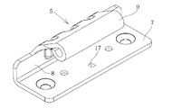
箱本体側蝶番金具5は図2から図5に示すように、取付板部7、立上げ部8、蝶番管部9を備えている。取付板部7は箱本体1の枠部4にねじで固定される部分であり、取付用のねじ孔10が形成されている。立上げ部8は取付板部7の端部から箱本体1の表面側に向かって立ち上がるように湾曲形成された部分であり、その先端は斜めに折り曲げたうえで蝶番管部9が形成されている。蝶番管部9は蝶番ピン11が差し込まれる管状又は孔状の部分である。
As shown in FIGS. 2 to 5, the box
箱本体側蝶番金具5は、その立上げ部8とは反対側の開放側を箱本体1の外側に向けて取付けられる。また扉側蝶番金具6も対応する蝶番管部を備えるものであり、扉側蝶番金具6は溶接により扉2の折り曲げられた側部12に取付けられている。
The box body side
図2に示すように、第1の実施形態では、箱本体側蝶番金具5の取付板部7の中央部分に、蝶番管部9側に向かって突出する段部13が形成されている。この段部13は取付板部7の、立上げ部8とは反対側の開放側に位置する端面14から立上げ部8に向かって一定幅で延びている。そしてこの段部13に、開放側の端面14から差し込み可能な扉保護部材15が差し込まれている。この扉保護部材15は断面がコの字状の樹脂製部材であり、図3、図4のように下面先端のフック16を段部13の孔17に係合させて取付けられている。扉保護部材15は開放側の端面14から差し込むだけで、ワンタッチで取付け可能である。なお扉保護部材15は必ずしも樹脂製である必要はなく、ゴム製であっても差し支えない。
As shown in FIG. 2, in the first embodiment, a
上記した第1の実施形態では、扉保護部材15を取付板部7の段部13に取付けたが、図6に示す第2の実施形態のように、取付板部7を平板状としたまま扉保護部材15を取付けることもできる。
In the first embodiment described above, the
このように箱本体側蝶番金具5の取付板部7に扉保護部材15を取付けたので、扉2の取付時に図7に示すように扉2を箱本体1の蝶番3の上に一時的に置いた場合にも、扉2の側部12は扉保護部材15によって支持されることとなり、扉2の側部12を疵付くことのないように保護することができる。特に第1の実施形態では、段部13に扉保護部材15を差し込んだので、位置がずれることがなく、強固な取付けが可能である。また扉保護部材15の上面を取付板部7の上面から十分に高くすることができるので、扉2の保護効果に優れ、蝶番を鋳造により形成しなくても板材を折り曲げて形成したものであっても対応できる利点がある。
Since the
また、扉保護部材15を開放側の端面14から差し込む構造としたことにより、扉2を開放側に傾けたときに扉保護部材15が扉2の側部12から受ける横方向の荷重の方向と、扉保護部材15の差し込み方向とが一致するので、扉保護部材15が外れるおそれがない。なお図8は図7の状態から扉2を持ち上げて扉側蝶番金具6の蝶番管部9を箱本体側蝶番金具5の蝶番管部9と一致させ、蝶番ピン11を挿入した状態を示す。
In addition, since the
上記した第1及び第2の実施形態では、扉保護部材15を取付板部7の端面14から差し込んだが、図9に示す第3の実施形態のように、取付板部7に取付け孔18を形成し、取付板部7の表面に対して垂直方向(上方)から扉保護部材15を差し込むこともできる。この場合には扉保護部材15の頭部を取付け孔18よりも十分に大径にしておくものとする。
In the first and second embodiments described above, the
以上に説明したように、本発明においては、箱本体側蝶番金具5の取付板部7に差し込み可能な扉保護部材15を取付けたので、扉保護部材15の取付け作業は簡単である。また扉2の取付時に扉2を箱本体1の蝶番3の上に一時的に置いた場合にも、扉2の側部12を疵付くことのないように保護することができる利点がある。
As described above, in the present invention, since the
1 箱本体
2 扉
3 蝶番
4 枠部
5 箱本体側蝶番金具
6 扉側蝶番金具
7 取付板部
8 立上げ部
9 蝶番管部
10 ねじ孔
11 蝶番ピン
12 側部
13 段部
14 端面
15 扉保護部材
16 フック
17 孔
18 取付け孔
DESCRIPTION OF
Claims (4)
Priority Applications (1)
| Application Number | Priority Date | Filing Date | Title |
|---|---|---|---|
| JP2013089135A JP6212726B2 (en) | 2013-04-22 | 2013-04-22 | Storage box for electrical and electronic equipment |
Applications Claiming Priority (1)
| Application Number | Priority Date | Filing Date | Title |
|---|---|---|---|
| JP2013089135A JP6212726B2 (en) | 2013-04-22 | 2013-04-22 | Storage box for electrical and electronic equipment |
Publications (2)
| Publication Number | Publication Date |
|---|---|
| JP2014212281A JP2014212281A (en) | 2014-11-13 |
| JP6212726B2 true JP6212726B2 (en) | 2017-10-18 |
Family
ID=51931802
Family Applications (1)
| Application Number | Title | Priority Date | Filing Date |
|---|---|---|---|
| JP2013089135A Active JP6212726B2 (en) | 2013-04-22 | 2013-04-22 | Storage box for electrical and electronic equipment |
Country Status (1)
| Country | Link |
|---|---|
| JP (1) | JP6212726B2 (en) |
Family Cites Families (4)
| Publication number | Priority date | Publication date | Assignee | Title |
|---|---|---|---|---|
| JPS5519803Y2 (en) * | 1975-08-18 | 1980-05-12 | ||
| JPS5849506U (en) * | 1981-09-25 | 1983-04-04 | 日東工業株式会社 | Lid box pivot device for switchboard cases |
| JPH0526223Y2 (en) * | 1987-08-20 | 1993-07-01 | ||
| JP4504472B2 (en) * | 1999-03-31 | 2010-07-14 | 日東工業株式会社 | Door drooping prevention member for electrical equipment storage box |
-
2013
- 2013-04-22 JP JP2013089135A patent/JP6212726B2/en active Active
Also Published As
| Publication number | Publication date |
|---|---|
| JP2014212281A (en) | 2014-11-13 |
Similar Documents
| Publication | Publication Date | Title |
|---|---|---|
| JPWO2017022068A1 (en) | Assembly structure of electronic device casing and electronic device | |
| JP6178652B2 (en) | cover | |
| JP6212726B2 (en) | Storage box for electrical and electronic equipment | |
| JP6014857B2 (en) | Door holding member for electrical equipment storage box | |
| KR100824341B1 (en) | Cable Fixture | |
| JP6548163B2 (en) | Joint reinforcement | |
| JP4630167B2 (en) | Wiring cover mounting structure | |
| JP5726337B2 (en) | Flexible cable deflection regulating structure and in-vehicle electronic device having the same | |
| JP2016226156A (en) | Electric equipment housing box | |
| JP5187971B2 (en) | Electrical equipment storage box | |
| CN104538164A (en) | Low-voltage current transformer box of transformer | |
| JP6323903B2 (en) | Electrical junction box | |
| JP5964105B2 (en) | Electronic device and electronic device casing applied thereto | |
| JP6366498B2 (en) | Electrical equipment storage box | |
| JP6356464B2 (en) | Electrical equipment storage box | |
| CN205545902U (en) | Speaker device | |
| JP4912272B2 (en) | Electrical and electronic equipment storage cabinet | |
| JP2009180443A (en) | Casing structure for outdoor unit of air conditioner | |
| JP5051715B2 (en) | Panel support bracket | |
| JP6444250B2 (en) | Electrical equipment storage box | |
| JP6347729B2 (en) | Electrical equipment storage box | |
| JP6231850B2 (en) | Fuse unit | |
| KR200469932Y1 (en) | Rear cover | |
| JP4752370B2 (en) | Power cord installation structure | |
| JP5657241B2 (en) | Equipment storage cabinet |
Legal Events
| Date | Code | Title | Description |
|---|---|---|---|
| A621 | Written request for application examination |
Free format text: JAPANESE INTERMEDIATE CODE: A621 Effective date: 20160223 |
|
| A977 | Report on retrieval |
Free format text: JAPANESE INTERMEDIATE CODE: A971007 Effective date: 20161130 |
|
| A131 | Notification of reasons for refusal |
Free format text: JAPANESE INTERMEDIATE CODE: A131 Effective date: 20161206 |
|
| A521 | Written amendment |
Free format text: JAPANESE INTERMEDIATE CODE: A523 Effective date: 20170201 |
|
| TRDD | Decision of grant or rejection written | ||
| A01 | Written decision to grant a patent or to grant a registration (utility model) |
Free format text: JAPANESE INTERMEDIATE CODE: A01 Effective date: 20170822 |
|
| A61 | First payment of annual fees (during grant procedure) |
Free format text: JAPANESE INTERMEDIATE CODE: A61 Effective date: 20170822 |
|
| R150 | Certificate of patent or registration of utility model |
Ref document number: 6212726 Country of ref document: JP Free format text: JAPANESE INTERMEDIATE CODE: R150 |