JP6208695B2 - Method for forming a continuous multilayer film - Google Patents
Method for forming a continuous multilayer film Download PDFInfo
- Publication number
- JP6208695B2 JP6208695B2 JP2014559880A JP2014559880A JP6208695B2 JP 6208695 B2 JP6208695 B2 JP 6208695B2 JP 2014559880 A JP2014559880 A JP 2014559880A JP 2014559880 A JP2014559880 A JP 2014559880A JP 6208695 B2 JP6208695 B2 JP 6208695B2
- Authority
- JP
- Japan
- Prior art keywords
- barrier film
- film
- multilayer
- protective layer
- layer
- Prior art date
- Legal status (The legal status is an assumption and is not a legal conclusion. Google has not performed a legal analysis and makes no representation as to the accuracy of the status listed.)
- Expired - Fee Related
Links
- 238000000034 method Methods 0.000 title claims description 63
- 230000004888 barrier function Effects 0.000 claims description 197
- 239000004820 Pressure-sensitive adhesive Substances 0.000 claims description 72
- 239000011241 protective layer Substances 0.000 claims description 66
- 239000000853 adhesive Substances 0.000 claims description 48
- 230000001070 adhesive effect Effects 0.000 claims description 48
- 229920002313 fluoropolymer Polymers 0.000 claims description 25
- 239000004811 fluoropolymer Substances 0.000 claims description 25
- 230000005540 biological transmission Effects 0.000 claims description 14
- 230000001681 protective effect Effects 0.000 claims description 14
- XLYOFNOQVPJJNP-UHFFFAOYSA-N water Chemical compound O XLYOFNOQVPJJNP-UHFFFAOYSA-N 0.000 claims description 10
- 239000010408 film Substances 0.000 description 253
- 239000010410 layer Substances 0.000 description 94
- 239000000758 substrate Substances 0.000 description 56
- -1 polyethylene terephthalate Polymers 0.000 description 35
- 229920000840 ethylene tetrafluoroethylene copolymer Polymers 0.000 description 29
- 239000000463 material Substances 0.000 description 27
- 229920000642 polymer Polymers 0.000 description 21
- 229920002367 Polyisobutene Polymers 0.000 description 18
- 239000000178 monomer Substances 0.000 description 17
- 229920001577 copolymer Polymers 0.000 description 15
- 230000032798 delamination Effects 0.000 description 15
- 239000000203 mixture Substances 0.000 description 15
- 238000012360 testing method Methods 0.000 description 15
- 229920005989 resin Polymers 0.000 description 13
- 239000011347 resin Substances 0.000 description 13
- 230000004224 protection Effects 0.000 description 12
- 239000003381 stabilizer Substances 0.000 description 12
- 239000000126 substance Substances 0.000 description 12
- 239000003963 antioxidant agent Substances 0.000 description 11
- 238000004519 manufacturing process Methods 0.000 description 11
- 229910052751 metal Inorganic materials 0.000 description 11
- 239000002184 metal Substances 0.000 description 11
- 229920006254 polymer film Polymers 0.000 description 10
- 230000008569 process Effects 0.000 description 10
- 239000011888 foil Substances 0.000 description 9
- 239000006097 ultraviolet radiation absorber Substances 0.000 description 9
- NIXOWILDQLNWCW-UHFFFAOYSA-M Acrylate Chemical compound [O-]C(=O)C=C NIXOWILDQLNWCW-UHFFFAOYSA-M 0.000 description 8
- 239000004215 Carbon black (E152) Substances 0.000 description 8
- 150000001412 amines Chemical class 0.000 description 8
- 230000000712 assembly Effects 0.000 description 8
- 238000000429 assembly Methods 0.000 description 8
- 230000015556 catabolic process Effects 0.000 description 8
- 238000000576 coating method Methods 0.000 description 8
- 238000006731 degradation reaction Methods 0.000 description 8
- 229930195733 hydrocarbon Natural products 0.000 description 8
- 150000002430 hydrocarbons Chemical class 0.000 description 8
- RRHGJUQNOFWUDK-UHFFFAOYSA-N Isoprene Chemical compound CC(=C)C=C RRHGJUQNOFWUDK-UHFFFAOYSA-N 0.000 description 7
- 239000002033 PVDF binder Substances 0.000 description 7
- NIXOWILDQLNWCW-UHFFFAOYSA-N acrylic acid group Chemical group C(C=C)(=O)O NIXOWILDQLNWCW-UHFFFAOYSA-N 0.000 description 7
- 229920000139 polyethylene terephthalate Polymers 0.000 description 7
- 239000005020 polyethylene terephthalate Substances 0.000 description 7
- 229920001296 polysiloxane Polymers 0.000 description 7
- 229920002981 polyvinylidene fluoride Polymers 0.000 description 7
- 239000004697 Polyetherimide Substances 0.000 description 6
- 239000004642 Polyimide Substances 0.000 description 6
- 229920009638 Tetrafluoroethylene-Hexafluoropropylene-Vinylidenefluoride Copolymer Polymers 0.000 description 6
- 239000006096 absorbing agent Substances 0.000 description 6
- 230000003078 antioxidant effect Effects 0.000 description 6
- 230000008901 benefit Effects 0.000 description 6
- 230000000052 comparative effect Effects 0.000 description 6
- 238000010276 construction Methods 0.000 description 6
- 239000002274 desiccant Substances 0.000 description 6
- 239000004611 light stabiliser Substances 0.000 description 6
- 229920001601 polyetherimide Polymers 0.000 description 6
- 229920001721 polyimide Polymers 0.000 description 6
- 230000001737 promoting effect Effects 0.000 description 6
- GHMLBKRAJCXXBS-UHFFFAOYSA-N resorcinol Chemical compound OC1=CC=CC(O)=C1 GHMLBKRAJCXXBS-UHFFFAOYSA-N 0.000 description 6
- 125000003866 trichloromethyl group Chemical group ClC(Cl)(Cl)* 0.000 description 6
- 239000004696 Poly ether ether ketone Substances 0.000 description 5
- QVGXLLKOCUKJST-UHFFFAOYSA-N atomic oxygen Chemical compound [O] QVGXLLKOCUKJST-UHFFFAOYSA-N 0.000 description 5
- 239000003431 cross linking reagent Substances 0.000 description 5
- 239000008393 encapsulating agent Substances 0.000 description 5
- 239000011521 glass Substances 0.000 description 5
- 239000001301 oxygen Substances 0.000 description 5
- 229910052760 oxygen Inorganic materials 0.000 description 5
- 239000003208 petroleum Substances 0.000 description 5
- 229920006260 polyaryletherketone Polymers 0.000 description 5
- 229920000728 polyester Polymers 0.000 description 5
- 229920002530 polyetherether ketone Polymers 0.000 description 5
- 238000006116 polymerization reaction Methods 0.000 description 5
- 230000005855 radiation Effects 0.000 description 5
- KAKZBPTYRLMSJV-UHFFFAOYSA-N Butadiene Chemical compound C=CC=C KAKZBPTYRLMSJV-UHFFFAOYSA-N 0.000 description 4
- VQTUBCCKSQIDNK-UHFFFAOYSA-N Isobutene Chemical group CC(C)=C VQTUBCCKSQIDNK-UHFFFAOYSA-N 0.000 description 4
- 239000004695 Polyether sulfone Substances 0.000 description 4
- XSQUKJJJFZCRTK-UHFFFAOYSA-N Urea Chemical compound NC(N)=O XSQUKJJJFZCRTK-UHFFFAOYSA-N 0.000 description 4
- 239000012790 adhesive layer Substances 0.000 description 4
- 239000004202 carbamide Substances 0.000 description 4
- 239000011248 coating agent Substances 0.000 description 4
- QHSJIZLJUFMIFP-UHFFFAOYSA-N ethene;1,1,2,2-tetrafluoroethene Chemical group C=C.FC(F)=C(F)F QHSJIZLJUFMIFP-UHFFFAOYSA-N 0.000 description 4
- 238000012986 modification Methods 0.000 description 4
- 230000004048 modification Effects 0.000 description 4
- 229920003023 plastic Polymers 0.000 description 4
- 239000004033 plastic Substances 0.000 description 4
- 229920000058 polyacrylate Polymers 0.000 description 4
- 229920002312 polyamide-imide Polymers 0.000 description 4
- 229920006393 polyether sulfone Polymers 0.000 description 4
- 239000011112 polyethylene naphthalate Substances 0.000 description 4
- 238000004381 surface treatment Methods 0.000 description 4
- 239000006188 syrup Substances 0.000 description 4
- 235000020357 syrup Nutrition 0.000 description 4
- 239000004962 Polyamide-imide Substances 0.000 description 3
- PPBRXRYQALVLMV-UHFFFAOYSA-N Styrene Chemical group C=CC1=CC=CC=C1 PPBRXRYQALVLMV-UHFFFAOYSA-N 0.000 description 3
- 239000012963 UV stabilizer Substances 0.000 description 3
- 238000010521 absorption reaction Methods 0.000 description 3
- 239000012298 atmosphere Substances 0.000 description 3
- 150000001875 compounds Chemical class 0.000 description 3
- 238000010894 electron beam technology Methods 0.000 description 3
- 238000005516 engineering process Methods 0.000 description 3
- 229920001038 ethylene copolymer Polymers 0.000 description 3
- 238000009472 formulation Methods 0.000 description 3
- 239000012760 heat stabilizer Substances 0.000 description 3
- 229920001519 homopolymer Polymers 0.000 description 3
- RAXXELZNTBOGNW-UHFFFAOYSA-N imidazole Natural products C1=CNC=N1 RAXXELZNTBOGNW-UHFFFAOYSA-N 0.000 description 3
- 239000003999 initiator Substances 0.000 description 3
- 229910052757 nitrogen Inorganic materials 0.000 description 3
- JRZJOMJEPLMPRA-UHFFFAOYSA-N olefin Natural products CCCCCCCC=C JRZJOMJEPLMPRA-UHFFFAOYSA-N 0.000 description 3
- 230000035699 permeability Effects 0.000 description 3
- 229920003207 poly(ethylene-2,6-naphthalate) Polymers 0.000 description 3
- 229920003223 poly(pyromellitimide-1,4-diphenyl ether) Polymers 0.000 description 3
- 229920000515 polycarbonate Polymers 0.000 description 3
- 239000004417 polycarbonate Substances 0.000 description 3
- 229920000098 polyolefin Polymers 0.000 description 3
- 230000002829 reductive effect Effects 0.000 description 3
- 239000002356 single layer Substances 0.000 description 3
- VZCYOOQTPOCHFL-UHFFFAOYSA-N trans-butenedioic acid Natural products OC(=O)C=CC(O)=O VZCYOOQTPOCHFL-UHFFFAOYSA-N 0.000 description 3
- 229910052724 xenon Inorganic materials 0.000 description 3
- FHNFHKCVQCLJFQ-UHFFFAOYSA-N xenon atom Chemical compound [Xe] FHNFHKCVQCLJFQ-UHFFFAOYSA-N 0.000 description 3
- LTYBJDPMCPTGEE-UHFFFAOYSA-N (4-benzoylphenyl) prop-2-enoate Chemical compound C1=CC(OC(=O)C=C)=CC=C1C(=O)C1=CC=CC=C1 LTYBJDPMCPTGEE-UHFFFAOYSA-N 0.000 description 2
- VXNZUUAINFGPBY-UHFFFAOYSA-N 1-Butene Chemical compound CCC=C VXNZUUAINFGPBY-UHFFFAOYSA-N 0.000 description 2
- YBYIRNPNPLQARY-UHFFFAOYSA-N 1H-indene Chemical compound C1=CC=C2CC=CC2=C1 YBYIRNPNPLQARY-UHFFFAOYSA-N 0.000 description 2
- KWVGIHKZDCUPEU-UHFFFAOYSA-N 2,2-dimethoxy-2-phenylacetophenone Chemical compound C=1C=CC=CC=1C(OC)(OC)C(=O)C1=CC=CC=C1 KWVGIHKZDCUPEU-UHFFFAOYSA-N 0.000 description 2
- UZUNCLSDTUBVCN-UHFFFAOYSA-N 2-(benzotriazol-2-yl)-6-(2-phenylpropan-2-yl)-4-(2,4,4-trimethylpentan-2-yl)phenol Chemical compound C=1C(C(C)(C)CC(C)(C)C)=CC(N2N=C3C=CC=CC3=N2)=C(O)C=1C(C)(C)C1=CC=CC=C1 UZUNCLSDTUBVCN-UHFFFAOYSA-N 0.000 description 2
- HRPVXLWXLXDGHG-UHFFFAOYSA-N Acrylamide Chemical compound NC(=O)C=C HRPVXLWXLXDGHG-UHFFFAOYSA-N 0.000 description 2
- XKRFYHLGVUSROY-UHFFFAOYSA-N Argon Chemical compound [Ar] XKRFYHLGVUSROY-UHFFFAOYSA-N 0.000 description 2
- IJGRMHOSHXDMSA-UHFFFAOYSA-N Atomic nitrogen Chemical compound N#N IJGRMHOSHXDMSA-UHFFFAOYSA-N 0.000 description 2
- OMPJBNCRMGITSC-UHFFFAOYSA-N Benzoylperoxide Chemical compound C=1C=CC=CC=1C(=O)OOC(=O)C1=CC=CC=C1 OMPJBNCRMGITSC-UHFFFAOYSA-N 0.000 description 2
- 239000004322 Butylated hydroxytoluene Substances 0.000 description 2
- NLZUEZXRPGMBCV-UHFFFAOYSA-N Butylhydroxytoluene Chemical compound CC1=CC(C(C)(C)C)=C(O)C(C(C)(C)C)=C1 NLZUEZXRPGMBCV-UHFFFAOYSA-N 0.000 description 2
- ZTQSAGDEMFDKMZ-UHFFFAOYSA-N Butyraldehyde Chemical compound CCCC=O ZTQSAGDEMFDKMZ-UHFFFAOYSA-N 0.000 description 2
- CURLTUGMZLYLDI-UHFFFAOYSA-N Carbon dioxide Chemical compound O=C=O CURLTUGMZLYLDI-UHFFFAOYSA-N 0.000 description 2
- 239000004971 Cross linker Substances 0.000 description 2
- VZCYOOQTPOCHFL-OWOJBTEDSA-N Fumaric acid Chemical compound OC(=O)\C=C\C(O)=O VZCYOOQTPOCHFL-OWOJBTEDSA-N 0.000 description 2
- UFHFLCQGNIYNRP-UHFFFAOYSA-N Hydrogen Chemical compound [H][H] UFHFLCQGNIYNRP-UHFFFAOYSA-N 0.000 description 2
- OFOBLEOULBTSOW-UHFFFAOYSA-N Malonic acid Chemical compound OC(=O)CC(O)=O OFOBLEOULBTSOW-UHFFFAOYSA-N 0.000 description 2
- CERQOIWHTDAKMF-UHFFFAOYSA-N Methacrylic acid Chemical compound CC(=C)C(O)=O CERQOIWHTDAKMF-UHFFFAOYSA-N 0.000 description 2
- 229920005987 OPPANOL® Polymers 0.000 description 2
- OFBQJSOFQDEBGM-UHFFFAOYSA-N Pentane Chemical compound CCCCC OFBQJSOFQDEBGM-UHFFFAOYSA-N 0.000 description 2
- 235000000126 Styrax benzoin Nutrition 0.000 description 2
- 244000028419 Styrax benzoin Species 0.000 description 2
- 235000008411 Sumatra benzointree Nutrition 0.000 description 2
- KKEYFWRCBNTPAC-UHFFFAOYSA-N Terephthalic acid Chemical compound OC(=O)C1=CC=C(C(O)=O)C=C1 KKEYFWRCBNTPAC-UHFFFAOYSA-N 0.000 description 2
- QYKIQEUNHZKYBP-UHFFFAOYSA-N Vinyl ether Chemical compound C=COC=C QYKIQEUNHZKYBP-UHFFFAOYSA-N 0.000 description 2
- KTSFMFGEAAANTF-UHFFFAOYSA-N [Cu].[Se].[Se].[In] Chemical compound [Cu].[Se].[Se].[In] KTSFMFGEAAANTF-UHFFFAOYSA-N 0.000 description 2
- 238000005299 abrasion Methods 0.000 description 2
- 229910052782 aluminium Inorganic materials 0.000 description 2
- XAGFODPZIPBFFR-UHFFFAOYSA-N aluminium Chemical compound [Al] XAGFODPZIPBFFR-UHFFFAOYSA-N 0.000 description 2
- VSCWAEJMTAWNJL-UHFFFAOYSA-K aluminium trichloride Chemical compound Cl[Al](Cl)Cl VSCWAEJMTAWNJL-UHFFFAOYSA-K 0.000 description 2
- 230000003373 anti-fouling effect Effects 0.000 description 2
- 125000003118 aryl group Chemical group 0.000 description 2
- 239000002585 base Substances 0.000 description 2
- 229960002130 benzoin Drugs 0.000 description 2
- WTEOIRVLGSZEPR-UHFFFAOYSA-N boron trifluoride Chemical compound FB(F)F WTEOIRVLGSZEPR-UHFFFAOYSA-N 0.000 description 2
- 229940095259 butylated hydroxytoluene Drugs 0.000 description 2
- 235000010354 butylated hydroxytoluene Nutrition 0.000 description 2
- 238000007334 copolymerization reaction Methods 0.000 description 2
- HVMJUDPAXRRVQO-UHFFFAOYSA-N copper indium Chemical compound [Cu].[In] HVMJUDPAXRRVQO-UHFFFAOYSA-N 0.000 description 2
- ISAOCJYIOMOJEB-UHFFFAOYSA-N desyl alcohol Natural products C=1C=CC=CC=1C(O)C(=O)C1=CC=CC=C1 ISAOCJYIOMOJEB-UHFFFAOYSA-N 0.000 description 2
- ZZEMEJKDTZOXOI-UHFFFAOYSA-N digallium;selenium(2-) Chemical compound [Ga+3].[Ga+3].[Se-2].[Se-2].[Se-2] ZZEMEJKDTZOXOI-UHFFFAOYSA-N 0.000 description 2
- 239000005038 ethylene vinyl acetate Substances 0.000 description 2
- 230000005281 excited state Effects 0.000 description 2
- 235000019382 gum benzoic Nutrition 0.000 description 2
- 239000001257 hydrogen Substances 0.000 description 2
- 229910052739 hydrogen Inorganic materials 0.000 description 2
- 238000005304 joining Methods 0.000 description 2
- 238000010030 laminating Methods 0.000 description 2
- 239000012939 laminating adhesive Substances 0.000 description 2
- VZCYOOQTPOCHFL-UPHRSURJSA-N maleic acid Chemical compound OC(=O)\C=C/C(O)=O VZCYOOQTPOCHFL-UPHRSURJSA-N 0.000 description 2
- 230000003287 optical effect Effects 0.000 description 2
- ISWSIDIOOBJBQZ-UHFFFAOYSA-N phenol group Chemical group C1(=CC=CC=C1)O ISWSIDIOOBJBQZ-UHFFFAOYSA-N 0.000 description 2
- 229920001230 polyarylate Polymers 0.000 description 2
- 239000003505 polymerization initiator Substances 0.000 description 2
- 230000000379 polymerizing effect Effects 0.000 description 2
- 238000002203 pretreatment Methods 0.000 description 2
- 238000007639 printing Methods 0.000 description 2
- 238000000197 pyrolysis Methods 0.000 description 2
- 238000000926 separation method Methods 0.000 description 2
- 125000006850 spacer group Chemical group 0.000 description 2
- 238000001228 spectrum Methods 0.000 description 2
- 230000035882 stress Effects 0.000 description 2
- 238000009823 thermal lamination Methods 0.000 description 2
- 238000012546 transfer Methods 0.000 description 2
- 238000011282 treatment Methods 0.000 description 2
- 239000004711 α-olefin Substances 0.000 description 2
- PSGCQDPCAWOCSH-UHFFFAOYSA-N (4,7,7-trimethyl-3-bicyclo[2.2.1]heptanyl) prop-2-enoate Chemical compound C1CC2(C)C(OC(=O)C=C)CC1C2(C)C PSGCQDPCAWOCSH-UHFFFAOYSA-N 0.000 description 1
- PMJHHCWVYXUKFD-SNAWJCMRSA-N (E)-1,3-pentadiene Chemical compound C\C=C\C=C PMJHHCWVYXUKFD-SNAWJCMRSA-N 0.000 description 1
- MYWOJODOMFBVCB-UHFFFAOYSA-N 1,2,6-trimethylphenanthrene Chemical compound CC1=CC=C2C3=CC(C)=CC=C3C=CC2=C1C MYWOJODOMFBVCB-UHFFFAOYSA-N 0.000 description 1
- MSAHTMIQULFMRG-UHFFFAOYSA-N 1,2-diphenyl-2-propan-2-yloxyethanone Chemical compound C=1C=CC=CC=1C(OC(C)C)C(=O)C1=CC=CC=C1 MSAHTMIQULFMRG-UHFFFAOYSA-N 0.000 description 1
- 229940008841 1,6-hexamethylene diisocyanate Drugs 0.000 description 1
- LGJCFVYMIJLQJO-UHFFFAOYSA-N 1-dodecylperoxydodecane Chemical compound CCCCCCCCCCCCOOCCCCCCCCCCCC LGJCFVYMIJLQJO-UHFFFAOYSA-N 0.000 description 1
- JWYVGKFDLWWQJX-UHFFFAOYSA-N 1-ethenylazepan-2-one Chemical compound C=CN1CCCCCC1=O JWYVGKFDLWWQJX-UHFFFAOYSA-N 0.000 description 1
- LMAUULKNZLEMGN-UHFFFAOYSA-N 1-ethyl-3,5-dimethylbenzene Chemical compound CCC1=CC(C)=CC(C)=C1 LMAUULKNZLEMGN-UHFFFAOYSA-N 0.000 description 1
- HECLRDQVFMWTQS-RGOKHQFPSA-N 1755-01-7 Chemical class C1[C@H]2[C@@H]3CC=C[C@@H]3[C@@H]1C=C2 HECLRDQVFMWTQS-RGOKHQFPSA-N 0.000 description 1
- ZWWKXEXFVYBART-UHFFFAOYSA-N 2,5-diisocyanato-5-methylcyclohexa-1,3-diene Chemical compound O=C=NC1(C)CC=C(N=C=O)C=C1 ZWWKXEXFVYBART-UHFFFAOYSA-N 0.000 description 1
- OZAIFHULBGXAKX-UHFFFAOYSA-N 2-(2-cyanopropan-2-yldiazenyl)-2-methylpropanenitrile Chemical compound N#CC(C)(C)N=NC(C)(C)C#N OZAIFHULBGXAKX-UHFFFAOYSA-N 0.000 description 1
- SMZOUWXMTYCWNB-UHFFFAOYSA-N 2-(2-methoxy-5-methylphenyl)ethanamine Chemical compound COC1=CC=C(C)C=C1CCN SMZOUWXMTYCWNB-UHFFFAOYSA-N 0.000 description 1
- JAHNSTQSQJOJLO-UHFFFAOYSA-N 2-(3-fluorophenyl)-1h-imidazole Chemical compound FC1=CC=CC(C=2NC=CN=2)=C1 JAHNSTQSQJOJLO-UHFFFAOYSA-N 0.000 description 1
- ZMWRRFHBXARRRT-UHFFFAOYSA-N 2-(benzotriazol-2-yl)-4,6-bis(2-methylbutan-2-yl)phenol Chemical compound CCC(C)(C)C1=CC(C(C)(C)CC)=CC(N2N=C3C=CC=CC3=N2)=C1O ZMWRRFHBXARRRT-UHFFFAOYSA-N 0.000 description 1
- GOXQRTZXKQZDDN-UHFFFAOYSA-N 2-Ethylhexyl acrylate Chemical compound CCCCC(CC)COC(=O)C=C GOXQRTZXKQZDDN-UHFFFAOYSA-N 0.000 description 1
- WFUGQJXVXHBTEM-UHFFFAOYSA-N 2-hydroperoxy-2-(2-hydroperoxybutan-2-ylperoxy)butane Chemical compound CCC(C)(OO)OOC(C)(CC)OO WFUGQJXVXHBTEM-UHFFFAOYSA-N 0.000 description 1
- LRRQSCPPOIUNGX-UHFFFAOYSA-N 2-hydroxy-1,2-bis(4-methoxyphenyl)ethanone Chemical compound C1=CC(OC)=CC=C1C(O)C(=O)C1=CC=C(OC)C=C1 LRRQSCPPOIUNGX-UHFFFAOYSA-N 0.000 description 1
- XMLYCEVDHLAQEL-UHFFFAOYSA-N 2-hydroxy-2-methyl-1-phenylpropan-1-one Chemical compound CC(C)(O)C(=O)C1=CC=CC=C1 XMLYCEVDHLAQEL-UHFFFAOYSA-N 0.000 description 1
- OMIGHNLMNHATMP-UHFFFAOYSA-N 2-hydroxyethyl prop-2-enoate Chemical compound OCCOC(=O)C=C OMIGHNLMNHATMP-UHFFFAOYSA-N 0.000 description 1
- BQZJOQXSCSZQPS-UHFFFAOYSA-N 2-methoxy-1,2-diphenylethanone Chemical compound C=1C=CC=CC=1C(OC)C(=O)C1=CC=CC=C1 BQZJOQXSCSZQPS-UHFFFAOYSA-N 0.000 description 1
- RIWRBSMFKVOJMN-UHFFFAOYSA-N 2-methyl-1-phenylpropan-2-ol Chemical compound CC(C)(O)CC1=CC=CC=C1 RIWRBSMFKVOJMN-UHFFFAOYSA-N 0.000 description 1
- NCTBYWFEJFTVEL-UHFFFAOYSA-N 2-methylbutyl prop-2-enoate Chemical compound CCC(C)COC(=O)C=C NCTBYWFEJFTVEL-UHFFFAOYSA-N 0.000 description 1
- KUDUQBURMYMBIJ-UHFFFAOYSA-N 2-prop-2-enoyloxyethyl prop-2-enoate Chemical compound C=CC(=O)OCCOC(=O)C=C KUDUQBURMYMBIJ-UHFFFAOYSA-N 0.000 description 1
- AIBRSVLEQRWAEG-UHFFFAOYSA-N 3,9-bis(2,4-ditert-butylphenoxy)-2,4,8,10-tetraoxa-3,9-diphosphaspiro[5.5]undecane Chemical compound CC(C)(C)C1=CC(C(C)(C)C)=CC=C1OP1OCC2(COP(OC=3C(=CC(=CC=3)C(C)(C)C)C(C)(C)C)OC2)CO1 AIBRSVLEQRWAEG-UHFFFAOYSA-N 0.000 description 1
- FRIBMENBGGCKPD-UHFFFAOYSA-N 3-(2,3-dimethoxyphenyl)prop-2-enal Chemical compound COC1=CC=CC(C=CC=O)=C1OC FRIBMENBGGCKPD-UHFFFAOYSA-N 0.000 description 1
- ZVYGIPWYVVJFRW-UHFFFAOYSA-N 3-methylbutyl prop-2-enoate Chemical compound CC(C)CCOC(=O)C=C ZVYGIPWYVVJFRW-UHFFFAOYSA-N 0.000 description 1
- ATVJXMYDOSMEPO-UHFFFAOYSA-N 3-prop-2-enoxyprop-1-ene Chemical compound C=CCOCC=C ATVJXMYDOSMEPO-UHFFFAOYSA-N 0.000 description 1
- BVDBXCXQMHBGQM-UHFFFAOYSA-N 4-methylpentan-2-yl prop-2-enoate Chemical compound CC(C)CC(C)OC(=O)C=C BVDBXCXQMHBGQM-UHFFFAOYSA-N 0.000 description 1
- YXHRTMJUSBVGMX-UHFFFAOYSA-N 4-n-butyl-2-n,4-n-bis(2,2,6,6-tetramethylpiperidin-4-yl)-2-n-[6-[(2,2,6,6-tetramethylpiperidin-4-yl)amino]hexyl]-1,3,5-triazine-2,4-diamine Chemical compound N=1C=NC(N(CCCCCCNC2CC(C)(C)NC(C)(C)C2)C2CC(C)(C)NC(C)(C)C2)=NC=1N(CCCC)C1CC(C)(C)NC(C)(C)C1 YXHRTMJUSBVGMX-UHFFFAOYSA-N 0.000 description 1
- DXPPIEDUBFUSEZ-UHFFFAOYSA-N 6-methylheptyl prop-2-enoate Chemical compound CC(C)CCCCCOC(=O)C=C DXPPIEDUBFUSEZ-UHFFFAOYSA-N 0.000 description 1
- FIHBHSQYSYVZQE-UHFFFAOYSA-N 6-prop-2-enoyloxyhexyl prop-2-enoate Chemical compound C=CC(=O)OCCCCCCOC(=O)C=C FIHBHSQYSYVZQE-UHFFFAOYSA-N 0.000 description 1
- CUXGDKOCSSIRKK-UHFFFAOYSA-N 7-methyloctyl prop-2-enoate Chemical compound CC(C)CCCCCCOC(=O)C=C CUXGDKOCSSIRKK-UHFFFAOYSA-N 0.000 description 1
- QGZKDVFQNNGYKY-UHFFFAOYSA-N Ammonia Chemical compound N QGZKDVFQNNGYKY-UHFFFAOYSA-N 0.000 description 1
- 229910015900 BF3 Inorganic materials 0.000 description 1
- 229920002799 BoPET Polymers 0.000 description 1
- BVKZGUZCCUSVTD-UHFFFAOYSA-L Carbonate Chemical compound [O-]C([O-])=O BVKZGUZCCUSVTD-UHFFFAOYSA-L 0.000 description 1
- 229910004613 CdTe Inorganic materials 0.000 description 1
- 229920001634 Copolyester Polymers 0.000 description 1
- 229920000089 Cyclic olefin copolymer Polymers 0.000 description 1
- LCGLNKUTAGEVQW-UHFFFAOYSA-N Dimethyl ether Chemical compound COC LCGLNKUTAGEVQW-UHFFFAOYSA-N 0.000 description 1
- 229920006358 Fluon Polymers 0.000 description 1
- 229910001218 Gallium arsenide Inorganic materials 0.000 description 1
- 239000004831 Hot glue Substances 0.000 description 1
- 229920013646 Hycar Polymers 0.000 description 1
- CERQOIWHTDAKMF-UHFFFAOYSA-M Methacrylate Chemical compound CC(=C)C([O-])=O CERQOIWHTDAKMF-UHFFFAOYSA-M 0.000 description 1
- WHNWPMSKXPGLAX-UHFFFAOYSA-N N-Vinyl-2-pyrrolidone Chemical compound C=CN1CCCC1=O WHNWPMSKXPGLAX-UHFFFAOYSA-N 0.000 description 1
- 229920000459 Nitrile rubber Polymers 0.000 description 1
- 229910019142 PO4 Inorganic materials 0.000 description 1
- OAICVXFJPJFONN-UHFFFAOYSA-N Phosphorus Chemical compound [P] OAICVXFJPJFONN-UHFFFAOYSA-N 0.000 description 1
- 229920012266 Poly(ether sulfone) PES Polymers 0.000 description 1
- 239000004721 Polyphenylene oxide Substances 0.000 description 1
- 239000004743 Polypropylene Substances 0.000 description 1
- XUIMIQQOPSSXEZ-UHFFFAOYSA-N Silicon Chemical compound [Si] XUIMIQQOPSSXEZ-UHFFFAOYSA-N 0.000 description 1
- 229920006355 Tefzel Polymers 0.000 description 1
- 241000727732 Tokoyo Species 0.000 description 1
- DAKWPKUUDNSNPN-UHFFFAOYSA-N Trimethylolpropane triacrylate Chemical compound C=CC(=O)OCC(CC)(COC(=O)C=C)COC(=O)C=C DAKWPKUUDNSNPN-UHFFFAOYSA-N 0.000 description 1
- 229920004738 ULTEM® Polymers 0.000 description 1
- 229920001646 UPILEX Polymers 0.000 description 1
- 230000006750 UV protection Effects 0.000 description 1
- QROGIFZRVHSFLM-QHHAFSJGSA-N [(e)-prop-1-enyl]benzene Chemical compound C\C=C\C1=CC=CC=C1 QROGIFZRVHSFLM-QHHAFSJGSA-N 0.000 description 1
- BGYHLZZASRKEJE-UHFFFAOYSA-N [3-[3-(3,5-ditert-butyl-4-hydroxyphenyl)propanoyloxy]-2,2-bis[3-(3,5-ditert-butyl-4-hydroxyphenyl)propanoyloxymethyl]propyl] 3-(3,5-ditert-butyl-4-hydroxyphenyl)propanoate Chemical compound CC(C)(C)C1=C(O)C(C(C)(C)C)=CC(CCC(=O)OCC(COC(=O)CCC=2C=C(C(O)=C(C=2)C(C)(C)C)C(C)(C)C)(COC(=O)CCC=2C=C(C(O)=C(C=2)C(C)(C)C)C(C)(C)C)COC(=O)CCC=2C=C(C(O)=C(C=2)C(C)(C)C)C(C)(C)C)=C1 BGYHLZZASRKEJE-UHFFFAOYSA-N 0.000 description 1
- 230000032900 absorption of visible light Effects 0.000 description 1
- 238000000862 absorption spectrum Methods 0.000 description 1
- GTDPSWPPOUPBNX-UHFFFAOYSA-N ac1mqpva Chemical compound CC12C(=O)OC(=O)C1(C)C1(C)C2(C)C(=O)OC1=O GTDPSWPPOUPBNX-UHFFFAOYSA-N 0.000 description 1
- 150000008062 acetophenones Chemical class 0.000 description 1
- 150000001252 acrylic acid derivatives Chemical class 0.000 description 1
- 239000000654 additive Substances 0.000 description 1
- 230000002411 adverse Effects 0.000 description 1
- 125000002723 alicyclic group Chemical group 0.000 description 1
- 239000012670 alkaline solution Substances 0.000 description 1
- XYLMUPLGERFSHI-UHFFFAOYSA-N alpha-Methylstyrene Chemical compound CC(=C)C1=CC=CC=C1 XYLMUPLGERFSHI-UHFFFAOYSA-N 0.000 description 1
- 150000001408 amides Chemical class 0.000 description 1
- 229910021417 amorphous silicon Inorganic materials 0.000 description 1
- 238000004458 analytical method Methods 0.000 description 1
- 238000013459 approach Methods 0.000 description 1
- 229910052786 argon Inorganic materials 0.000 description 1
- 238000000231 atomic layer deposition Methods 0.000 description 1
- 230000009286 beneficial effect Effects 0.000 description 1
- NEFJPHDWZWTFQC-UHFFFAOYSA-N benzene-1,3-dicarboxylic acid;benzene-1,3-diol Chemical compound OC1=CC=CC(O)=C1.OC(=O)C1=CC=CC(C(O)=O)=C1 NEFJPHDWZWTFQC-UHFFFAOYSA-N 0.000 description 1
- WPYMKLBDIGXBTP-UHFFFAOYSA-N benzoic acid Chemical compound OC(=O)C1=CC=CC=C1 WPYMKLBDIGXBTP-UHFFFAOYSA-N 0.000 description 1
- RWCCWEUUXYIKHB-UHFFFAOYSA-N benzophenone Chemical compound C=1C=CC=CC=1C(=O)C1=CC=CC=C1 RWCCWEUUXYIKHB-UHFFFAOYSA-N 0.000 description 1
- 239000012965 benzophenone Substances 0.000 description 1
- 235000019400 benzoyl peroxide Nutrition 0.000 description 1
- XITRBUPOXXBIJN-UHFFFAOYSA-N bis(2,2,6,6-tetramethylpiperidin-4-yl) decanedioate Chemical compound C1C(C)(C)NC(C)(C)CC1OC(=O)CCCCCCCCC(=O)OC1CC(C)(C)NC(C)(C)C1 XITRBUPOXXBIJN-UHFFFAOYSA-N 0.000 description 1
- 229920001400 block copolymer Polymers 0.000 description 1
- 230000000903 blocking effect Effects 0.000 description 1
- 239000004566 building material Substances 0.000 description 1
- OCWYEMOEOGEQAN-UHFFFAOYSA-N bumetrizole Chemical compound CC(C)(C)C1=CC(C)=CC(N2N=C3C=C(Cl)C=CC3=N2)=C1O OCWYEMOEOGEQAN-UHFFFAOYSA-N 0.000 description 1
- DQXBYHZEEUGOBF-UHFFFAOYSA-N but-3-enoic acid;ethene Chemical compound C=C.OC(=O)CC=C DQXBYHZEEUGOBF-UHFFFAOYSA-N 0.000 description 1
- IAQRGUVFOMOMEM-UHFFFAOYSA-N butene Natural products CC=CC IAQRGUVFOMOMEM-UHFFFAOYSA-N 0.000 description 1
- DKVNPHBNOWQYFE-UHFFFAOYSA-N carbamodithioic acid Chemical compound NC(S)=S DKVNPHBNOWQYFE-UHFFFAOYSA-N 0.000 description 1
- 150000001721 carbon Chemical class 0.000 description 1
- 229910002092 carbon dioxide Inorganic materials 0.000 description 1
- 239000001569 carbon dioxide Substances 0.000 description 1
- 125000002843 carboxylic acid group Chemical group 0.000 description 1
- 238000006243 chemical reaction Methods 0.000 description 1
- 238000005229 chemical vapour deposition Methods 0.000 description 1
- UUAGAQFQZIEFAH-UHFFFAOYSA-N chlorotrifluoroethylene Chemical compound FC(F)=C(F)Cl UUAGAQFQZIEFAH-UHFFFAOYSA-N 0.000 description 1
- 239000000109 continuous material Substances 0.000 description 1
- 238000004132 cross linking Methods 0.000 description 1
- 229910021419 crystalline silicon Inorganic materials 0.000 description 1
- BLCKNMAZFRMCJJ-UHFFFAOYSA-N cyclohexyl cyclohexyloxycarbonyloxy carbonate Chemical compound C1CCCCC1OC(=O)OOC(=O)OC1CCCCC1 BLCKNMAZFRMCJJ-UHFFFAOYSA-N 0.000 description 1
- KBLWLMPSVYBVDK-UHFFFAOYSA-N cyclohexyl prop-2-enoate Chemical compound C=CC(=O)OC1CCCCC1 KBLWLMPSVYBVDK-UHFFFAOYSA-N 0.000 description 1
- 238000005034 decoration Methods 0.000 description 1
- FWLDHHJLVGRRHD-UHFFFAOYSA-N decyl prop-2-enoate Chemical compound CCCCCCCCCCOC(=O)C=C FWLDHHJLVGRRHD-UHFFFAOYSA-N 0.000 description 1
- 238000011161 development Methods 0.000 description 1
- LSXWFXONGKSEMY-UHFFFAOYSA-N di-tert-butyl peroxide Chemical compound CC(C)(C)OOC(C)(C)C LSXWFXONGKSEMY-UHFFFAOYSA-N 0.000 description 1
- 238000010586 diagram Methods 0.000 description 1
- 238000002845 discoloration Methods 0.000 description 1
- 239000012990 dithiocarbamate Substances 0.000 description 1
- 150000002148 esters Chemical class 0.000 description 1
- 238000011156 evaluation Methods 0.000 description 1
- 239000003063 flame retardant Substances 0.000 description 1
- 239000001530 fumaric acid Substances 0.000 description 1
- 235000010985 glycerol esters of wood rosin Nutrition 0.000 description 1
- 229910052736 halogen Inorganic materials 0.000 description 1
- 150000002367 halogens Chemical class 0.000 description 1
- 229910052734 helium Inorganic materials 0.000 description 1
- 239000001307 helium Substances 0.000 description 1
- SWQJXJOGLNCZEY-UHFFFAOYSA-N helium atom Chemical compound [He] SWQJXJOGLNCZEY-UHFFFAOYSA-N 0.000 description 1
- RRAMGCGOFNQTLD-UHFFFAOYSA-N hexamethylene diisocyanate Chemical compound O=C=NCCCCCCN=C=O RRAMGCGOFNQTLD-UHFFFAOYSA-N 0.000 description 1
- 238000005984 hydrogenation reaction Methods 0.000 description 1
- 150000003949 imides Chemical class 0.000 description 1
- AMGQUBHHOARCQH-UHFFFAOYSA-N indium;oxotin Chemical compound [In].[Sn]=O AMGQUBHHOARCQH-UHFFFAOYSA-N 0.000 description 1
- 238000007641 inkjet printing Methods 0.000 description 1
- 229910052809 inorganic oxide Inorganic materials 0.000 description 1
- 230000002452 interceptive effect Effects 0.000 description 1
- 229920000554 ionomer Polymers 0.000 description 1
- 230000001678 irradiating effect Effects 0.000 description 1
- 239000002655 kraft paper Substances 0.000 description 1
- 238000007648 laser printing Methods 0.000 description 1
- PBOSTUDLECTMNL-UHFFFAOYSA-N lauryl acrylate Chemical compound CCCCCCCCCCCCOC(=O)C=C PBOSTUDLECTMNL-UHFFFAOYSA-N 0.000 description 1
- 239000002346 layers by function Substances 0.000 description 1
- 238000007644 letterpress printing Methods 0.000 description 1
- 239000011968 lewis acid catalyst Substances 0.000 description 1
- 230000000670 limiting effect Effects 0.000 description 1
- 230000014759 maintenance of location Effects 0.000 description 1
- 239000011976 maleic acid Substances 0.000 description 1
- 239000003550 marker Substances 0.000 description 1
- 230000007246 mechanism Effects 0.000 description 1
- 239000012528 membrane Substances 0.000 description 1
- 239000007769 metal material Substances 0.000 description 1
- 229910044991 metal oxide Inorganic materials 0.000 description 1
- 150000004706 metal oxides Chemical class 0.000 description 1
- FQPSGWSUVKBHSU-UHFFFAOYSA-N methacrylamide Chemical compound CC(=C)C(N)=O FQPSGWSUVKBHSU-UHFFFAOYSA-N 0.000 description 1
- 125000005395 methacrylic acid group Chemical group 0.000 description 1
- LVHBHZANLOWSRM-UHFFFAOYSA-N methylenebutanedioic acid Natural products OC(=O)CC(=C)C(O)=O LVHBHZANLOWSRM-UHFFFAOYSA-N 0.000 description 1
- 230000003278 mimic effect Effects 0.000 description 1
- OVHHHVAVHBHXAK-UHFFFAOYSA-N n,n-diethylprop-2-enamide Chemical compound CCN(CC)C(=O)C=C OVHHHVAVHBHXAK-UHFFFAOYSA-N 0.000 description 1
- 229940088644 n,n-dimethylacrylamide Drugs 0.000 description 1
- YLGYACDQVQQZSW-UHFFFAOYSA-N n,n-dimethylprop-2-enamide Chemical compound CN(C)C(=O)C=C YLGYACDQVQQZSW-UHFFFAOYSA-N 0.000 description 1
- YSLAUVZTCDVIPD-UHFFFAOYSA-N n-(2,2-dihydroxyethyl)-n-ethylprop-2-enamide Chemical compound OC(O)CN(CC)C(=O)C=C YSLAUVZTCDVIPD-UHFFFAOYSA-N 0.000 description 1
- UUORTJUPDJJXST-UHFFFAOYSA-N n-(2-hydroxyethyl)prop-2-enamide Chemical compound OCCNC(=O)C=C UUORTJUPDJJXST-UHFFFAOYSA-N 0.000 description 1
- SWPMNMYLORDLJE-UHFFFAOYSA-N n-ethylprop-2-enamide Chemical compound CCNC(=O)C=C SWPMNMYLORDLJE-UHFFFAOYSA-N 0.000 description 1
- AWGZKFQMWZYCHF-UHFFFAOYSA-N n-octylprop-2-enamide Chemical compound CCCCCCCCNC(=O)C=C AWGZKFQMWZYCHF-UHFFFAOYSA-N 0.000 description 1
- 150000004767 nitrides Chemical class 0.000 description 1
- 229920006120 non-fluorinated polymer Polymers 0.000 description 1
- SSDSCDGVMJFTEQ-UHFFFAOYSA-N octadecyl 3-(3,5-ditert-butyl-4-hydroxyphenyl)propanoate Chemical compound CCCCCCCCCCCCCCCCCCOC(=O)CCC1=CC(C(C)(C)C)=C(O)C(C(C)(C)C)=C1 SSDSCDGVMJFTEQ-UHFFFAOYSA-N 0.000 description 1
- 238000007645 offset printing Methods 0.000 description 1
- 238000013086 organic photovoltaic Methods 0.000 description 1
- 238000010525 oxidative degradation reaction Methods 0.000 description 1
- 239000003973 paint Substances 0.000 description 1
- 230000002093 peripheral effect Effects 0.000 description 1
- 150000002978 peroxides Chemical class 0.000 description 1
- 239000010452 phosphate Substances 0.000 description 1
- 239000011574 phosphorus Substances 0.000 description 1
- 229910052698 phosphorus Inorganic materials 0.000 description 1
- 230000000704 physical effect Effects 0.000 description 1
- MXXWOMGUGJBKIW-YPCIICBESA-N piperine Chemical compound C=1C=C2OCOC2=CC=1/C=C/C=C/C(=O)N1CCCCC1 MXXWOMGUGJBKIW-YPCIICBESA-N 0.000 description 1
- 229940075559 piperine Drugs 0.000 description 1
- WVWHRXVVAYXKDE-UHFFFAOYSA-N piperine Natural products O=C(C=CC=Cc1ccc2OCOc2c1)C3CCCCN3 WVWHRXVVAYXKDE-UHFFFAOYSA-N 0.000 description 1
- 235000019100 piperine Nutrition 0.000 description 1
- PMJHHCWVYXUKFD-UHFFFAOYSA-N piperylene Natural products CC=CC=C PMJHHCWVYXUKFD-UHFFFAOYSA-N 0.000 description 1
- 229920001200 poly(ethylene-vinyl acetate) Polymers 0.000 description 1
- 229920003229 poly(methyl methacrylate) Polymers 0.000 description 1
- 229920003050 poly-cycloolefin Polymers 0.000 description 1
- 229920000570 polyether Polymers 0.000 description 1
- 229920000307 polymer substrate Polymers 0.000 description 1
- 239000004926 polymethyl methacrylate Substances 0.000 description 1
- 229920001155 polypropylene Polymers 0.000 description 1
- 239000004800 polyvinyl chloride Substances 0.000 description 1
- 229920000915 polyvinyl chloride Polymers 0.000 description 1
- 229920002620 polyvinyl fluoride Polymers 0.000 description 1
- HJWLCRVIBGQPNF-UHFFFAOYSA-N prop-2-enylbenzene Chemical compound C=CCC1=CC=CC=C1 HJWLCRVIBGQPNF-UHFFFAOYSA-N 0.000 description 1
- 238000010526 radical polymerization reaction Methods 0.000 description 1
- 229920005604 random copolymer Polymers 0.000 description 1
- 230000009467 reduction Effects 0.000 description 1
- 238000011160 research Methods 0.000 description 1
- 238000005096 rolling process Methods 0.000 description 1
- 238000007650 screen-printing Methods 0.000 description 1
- 239000004065 semiconductor Substances 0.000 description 1
- 229910052710 silicon Inorganic materials 0.000 description 1
- 239000010703 silicon Substances 0.000 description 1
- MSFGZHUJTJBYFA-UHFFFAOYSA-M sodium dichloroisocyanurate Chemical compound [Na+].ClN1C(=O)[N-]C(=O)N(Cl)C1=O MSFGZHUJTJBYFA-UHFFFAOYSA-M 0.000 description 1
- 239000002904 solvent Substances 0.000 description 1
- 230000002269 spontaneous effect Effects 0.000 description 1
- 238000004544 sputter deposition Methods 0.000 description 1
- 230000006641 stabilisation Effects 0.000 description 1
- 238000011105 stabilization Methods 0.000 description 1
- 238000007655 standard test method Methods 0.000 description 1
- 238000003860 storage Methods 0.000 description 1
- 229920006132 styrene block copolymer Polymers 0.000 description 1
- 150000003457 sulfones Chemical class 0.000 description 1
- 239000011593 sulfur Substances 0.000 description 1
- 229910052717 sulfur Inorganic materials 0.000 description 1
- ISXSCDLOGDJUNJ-UHFFFAOYSA-N tert-butyl prop-2-enoate Chemical compound CC(C)(C)OC(=O)C=C ISXSCDLOGDJUNJ-UHFFFAOYSA-N 0.000 description 1
- 238000005979 thermal decomposition reaction Methods 0.000 description 1
- 238000002207 thermal evaporation Methods 0.000 description 1
- 230000008646 thermal stress Effects 0.000 description 1
- 230000000930 thermomechanical effect Effects 0.000 description 1
- 229920002803 thermoplastic polyurethane Polymers 0.000 description 1
- 239000010409 thin film Substances 0.000 description 1
- 238000005809 transesterification reaction Methods 0.000 description 1
- 238000010023 transfer printing Methods 0.000 description 1
- 238000002834 transmittance Methods 0.000 description 1
- HGBOYTHUEUWSSQ-UHFFFAOYSA-N valeric aldehyde Natural products CCCCC=O HGBOYTHUEUWSSQ-UHFFFAOYSA-N 0.000 description 1
- 229920002554 vinyl polymer Polymers 0.000 description 1
- 238000009736 wetting Methods 0.000 description 1
Images


Classifications
-
- H—ELECTRICITY
- H01—ELECTRIC ELEMENTS
- H01L—SEMICONDUCTOR DEVICES NOT COVERED BY CLASS H10
- H01L31/00—Semiconductor devices sensitive to infrared radiation, light, electromagnetic radiation of shorter wavelength or corpuscular radiation and specially adapted either for the conversion of the energy of such radiation into electrical energy or for the control of electrical energy by such radiation; Processes or apparatus specially adapted for the manufacture or treatment thereof or of parts thereof; Details thereof
- H01L31/04—Semiconductor devices sensitive to infrared radiation, light, electromagnetic radiation of shorter wavelength or corpuscular radiation and specially adapted either for the conversion of the energy of such radiation into electrical energy or for the control of electrical energy by such radiation; Processes or apparatus specially adapted for the manufacture or treatment thereof or of parts thereof; Details thereof adapted as photovoltaic [PV] conversion devices
- H01L31/042—PV modules or arrays of single PV cells
- H01L31/048—Encapsulation of modules
-
- B—PERFORMING OPERATIONS; TRANSPORTING
- B32—LAYERED PRODUCTS
- B32B—LAYERED PRODUCTS, i.e. PRODUCTS BUILT-UP OF STRATA OF FLAT OR NON-FLAT, e.g. CELLULAR OR HONEYCOMB, FORM
- B32B15/00—Layered products comprising a layer of metal
- B32B15/04—Layered products comprising a layer of metal comprising metal as the main or only constituent of a layer, which is next to another layer of the same or of a different material
-
- B—PERFORMING OPERATIONS; TRANSPORTING
- B32—LAYERED PRODUCTS
- B32B—LAYERED PRODUCTS, i.e. PRODUCTS BUILT-UP OF STRATA OF FLAT OR NON-FLAT, e.g. CELLULAR OR HONEYCOMB, FORM
- B32B15/00—Layered products comprising a layer of metal
- B32B15/20—Layered products comprising a layer of metal comprising aluminium or copper
-
- B—PERFORMING OPERATIONS; TRANSPORTING
- B32—LAYERED PRODUCTS
- B32B—LAYERED PRODUCTS, i.e. PRODUCTS BUILT-UP OF STRATA OF FLAT OR NON-FLAT, e.g. CELLULAR OR HONEYCOMB, FORM
- B32B27/00—Layered products comprising a layer of synthetic resin
- B32B27/06—Layered products comprising a layer of synthetic resin as the main or only constituent of a layer, which is next to another layer of the same or of a different material
- B32B27/08—Layered products comprising a layer of synthetic resin as the main or only constituent of a layer, which is next to another layer of the same or of a different material of synthetic resin
-
- B—PERFORMING OPERATIONS; TRANSPORTING
- B32—LAYERED PRODUCTS
- B32B—LAYERED PRODUCTS, i.e. PRODUCTS BUILT-UP OF STRATA OF FLAT OR NON-FLAT, e.g. CELLULAR OR HONEYCOMB, FORM
- B32B27/00—Layered products comprising a layer of synthetic resin
- B32B27/28—Layered products comprising a layer of synthetic resin comprising synthetic resins not wholly covered by any one of the sub-groups B32B27/30 - B32B27/42
- B32B27/281—Layered products comprising a layer of synthetic resin comprising synthetic resins not wholly covered by any one of the sub-groups B32B27/30 - B32B27/42 comprising polyimides
-
- B—PERFORMING OPERATIONS; TRANSPORTING
- B32—LAYERED PRODUCTS
- B32B—LAYERED PRODUCTS, i.e. PRODUCTS BUILT-UP OF STRATA OF FLAT OR NON-FLAT, e.g. CELLULAR OR HONEYCOMB, FORM
- B32B27/00—Layered products comprising a layer of synthetic resin
- B32B27/28—Layered products comprising a layer of synthetic resin comprising synthetic resins not wholly covered by any one of the sub-groups B32B27/30 - B32B27/42
- B32B27/285—Layered products comprising a layer of synthetic resin comprising synthetic resins not wholly covered by any one of the sub-groups B32B27/30 - B32B27/42 comprising polyethers
-
- B—PERFORMING OPERATIONS; TRANSPORTING
- B32—LAYERED PRODUCTS
- B32B—LAYERED PRODUCTS, i.e. PRODUCTS BUILT-UP OF STRATA OF FLAT OR NON-FLAT, e.g. CELLULAR OR HONEYCOMB, FORM
- B32B27/00—Layered products comprising a layer of synthetic resin
- B32B27/28—Layered products comprising a layer of synthetic resin comprising synthetic resins not wholly covered by any one of the sub-groups B32B27/30 - B32B27/42
- B32B27/286—Layered products comprising a layer of synthetic resin comprising synthetic resins not wholly covered by any one of the sub-groups B32B27/30 - B32B27/42 comprising polysulphones; polysulfides
-
- B—PERFORMING OPERATIONS; TRANSPORTING
- B32—LAYERED PRODUCTS
- B32B—LAYERED PRODUCTS, i.e. PRODUCTS BUILT-UP OF STRATA OF FLAT OR NON-FLAT, e.g. CELLULAR OR HONEYCOMB, FORM
- B32B27/00—Layered products comprising a layer of synthetic resin
- B32B27/28—Layered products comprising a layer of synthetic resin comprising synthetic resins not wholly covered by any one of the sub-groups B32B27/30 - B32B27/42
- B32B27/288—Layered products comprising a layer of synthetic resin comprising synthetic resins not wholly covered by any one of the sub-groups B32B27/30 - B32B27/42 comprising polyketones
-
- B—PERFORMING OPERATIONS; TRANSPORTING
- B32—LAYERED PRODUCTS
- B32B—LAYERED PRODUCTS, i.e. PRODUCTS BUILT-UP OF STRATA OF FLAT OR NON-FLAT, e.g. CELLULAR OR HONEYCOMB, FORM
- B32B27/00—Layered products comprising a layer of synthetic resin
- B32B27/30—Layered products comprising a layer of synthetic resin comprising vinyl (co)polymers; comprising acrylic (co)polymers
- B32B27/304—Layered products comprising a layer of synthetic resin comprising vinyl (co)polymers; comprising acrylic (co)polymers comprising vinyl halide (co)polymers, e.g. PVC, PVDC, PVF, PVDF
-
- B—PERFORMING OPERATIONS; TRANSPORTING
- B32—LAYERED PRODUCTS
- B32B—LAYERED PRODUCTS, i.e. PRODUCTS BUILT-UP OF STRATA OF FLAT OR NON-FLAT, e.g. CELLULAR OR HONEYCOMB, FORM
- B32B27/00—Layered products comprising a layer of synthetic resin
- B32B27/32—Layered products comprising a layer of synthetic resin comprising polyolefins
-
- B—PERFORMING OPERATIONS; TRANSPORTING
- B32—LAYERED PRODUCTS
- B32B—LAYERED PRODUCTS, i.e. PRODUCTS BUILT-UP OF STRATA OF FLAT OR NON-FLAT, e.g. CELLULAR OR HONEYCOMB, FORM
- B32B27/00—Layered products comprising a layer of synthetic resin
- B32B27/36—Layered products comprising a layer of synthetic resin comprising polyesters
- B32B27/365—Layered products comprising a layer of synthetic resin comprising polyesters comprising polycarbonates
-
- B—PERFORMING OPERATIONS; TRANSPORTING
- B32—LAYERED PRODUCTS
- B32B—LAYERED PRODUCTS, i.e. PRODUCTS BUILT-UP OF STRATA OF FLAT OR NON-FLAT, e.g. CELLULAR OR HONEYCOMB, FORM
- B32B37/00—Methods or apparatus for laminating, e.g. by curing or by ultrasonic bonding
- B32B37/14—Methods or apparatus for laminating, e.g. by curing or by ultrasonic bonding characterised by the properties of the layers
- B32B37/16—Methods or apparatus for laminating, e.g. by curing or by ultrasonic bonding characterised by the properties of the layers with all layers existing as coherent layers before laminating
- B32B37/22—Methods or apparatus for laminating, e.g. by curing or by ultrasonic bonding characterised by the properties of the layers with all layers existing as coherent layers before laminating involving the assembly of both discrete and continuous layers
- B32B37/223—One or more of the layers being plastic
- B32B37/226—Laminating sheets, panels or inserts between two continuous plastic layers
-
- B—PERFORMING OPERATIONS; TRANSPORTING
- B32—LAYERED PRODUCTS
- B32B—LAYERED PRODUCTS, i.e. PRODUCTS BUILT-UP OF STRATA OF FLAT OR NON-FLAT, e.g. CELLULAR OR HONEYCOMB, FORM
- B32B7/00—Layered products characterised by the relation between layers; Layered products characterised by the relative orientation of features between layers, or by the relative values of a measurable parameter between layers, i.e. products comprising layers having different physical, chemical or physicochemical properties; Layered products characterised by the interconnection of layers
- B32B7/04—Interconnection of layers
- B32B7/12—Interconnection of layers using interposed adhesives or interposed materials with bonding properties
-
- B—PERFORMING OPERATIONS; TRANSPORTING
- B32—LAYERED PRODUCTS
- B32B—LAYERED PRODUCTS, i.e. PRODUCTS BUILT-UP OF STRATA OF FLAT OR NON-FLAT, e.g. CELLULAR OR HONEYCOMB, FORM
- B32B2250/00—Layers arrangement
- B32B2250/44—Number of layers variable across the laminate
-
- B—PERFORMING OPERATIONS; TRANSPORTING
- B32—LAYERED PRODUCTS
- B32B—LAYERED PRODUCTS, i.e. PRODUCTS BUILT-UP OF STRATA OF FLAT OR NON-FLAT, e.g. CELLULAR OR HONEYCOMB, FORM
- B32B2255/00—Coating on the layer surface
- B32B2255/10—Coating on the layer surface on synthetic resin layer or on natural or synthetic rubber layer
-
- B—PERFORMING OPERATIONS; TRANSPORTING
- B32—LAYERED PRODUCTS
- B32B—LAYERED PRODUCTS, i.e. PRODUCTS BUILT-UP OF STRATA OF FLAT OR NON-FLAT, e.g. CELLULAR OR HONEYCOMB, FORM
- B32B2255/00—Coating on the layer surface
- B32B2255/26—Polymeric coating
-
- B—PERFORMING OPERATIONS; TRANSPORTING
- B32—LAYERED PRODUCTS
- B32B—LAYERED PRODUCTS, i.e. PRODUCTS BUILT-UP OF STRATA OF FLAT OR NON-FLAT, e.g. CELLULAR OR HONEYCOMB, FORM
- B32B2307/00—Properties of the layers or laminate
- B32B2307/40—Properties of the layers or laminate having particular optical properties
- B32B2307/41—Opaque
-
- B—PERFORMING OPERATIONS; TRANSPORTING
- B32—LAYERED PRODUCTS
- B32B—LAYERED PRODUCTS, i.e. PRODUCTS BUILT-UP OF STRATA OF FLAT OR NON-FLAT, e.g. CELLULAR OR HONEYCOMB, FORM
- B32B2307/00—Properties of the layers or laminate
- B32B2307/50—Properties of the layers or laminate having particular mechanical properties
- B32B2307/54—Yield strength; Tensile strength
-
- B—PERFORMING OPERATIONS; TRANSPORTING
- B32—LAYERED PRODUCTS
- B32B—LAYERED PRODUCTS, i.e. PRODUCTS BUILT-UP OF STRATA OF FLAT OR NON-FLAT, e.g. CELLULAR OR HONEYCOMB, FORM
- B32B2307/00—Properties of the layers or laminate
- B32B2307/70—Other properties
- B32B2307/71—Resistive to light or to UV
-
- B—PERFORMING OPERATIONS; TRANSPORTING
- B32—LAYERED PRODUCTS
- B32B—LAYERED PRODUCTS, i.e. PRODUCTS BUILT-UP OF STRATA OF FLAT OR NON-FLAT, e.g. CELLULAR OR HONEYCOMB, FORM
- B32B2307/00—Properties of the layers or laminate
- B32B2307/70—Other properties
- B32B2307/712—Weather resistant
-
- B—PERFORMING OPERATIONS; TRANSPORTING
- B32—LAYERED PRODUCTS
- B32B—LAYERED PRODUCTS, i.e. PRODUCTS BUILT-UP OF STRATA OF FLAT OR NON-FLAT, e.g. CELLULAR OR HONEYCOMB, FORM
- B32B2307/00—Properties of the layers or laminate
- B32B2307/70—Other properties
- B32B2307/724—Permeability to gases, adsorption
- B32B2307/7242—Non-permeable
- B32B2307/7246—Water vapor barrier
-
- B—PERFORMING OPERATIONS; TRANSPORTING
- B32—LAYERED PRODUCTS
- B32B—LAYERED PRODUCTS, i.e. PRODUCTS BUILT-UP OF STRATA OF FLAT OR NON-FLAT, e.g. CELLULAR OR HONEYCOMB, FORM
- B32B2307/00—Properties of the layers or laminate
- B32B2307/70—Other properties
- B32B2307/726—Permeability to liquids, absorption
- B32B2307/7265—Non-permeable
-
- B—PERFORMING OPERATIONS; TRANSPORTING
- B32—LAYERED PRODUCTS
- B32B—LAYERED PRODUCTS, i.e. PRODUCTS BUILT-UP OF STRATA OF FLAT OR NON-FLAT, e.g. CELLULAR OR HONEYCOMB, FORM
- B32B2327/00—Polyvinylhalogenides
- B32B2327/12—Polyvinylhalogenides containing fluorine
-
- B—PERFORMING OPERATIONS; TRANSPORTING
- B32—LAYERED PRODUCTS
- B32B—LAYERED PRODUCTS, i.e. PRODUCTS BUILT-UP OF STRATA OF FLAT OR NON-FLAT, e.g. CELLULAR OR HONEYCOMB, FORM
- B32B2457/00—Electrical equipment
-
- B—PERFORMING OPERATIONS; TRANSPORTING
- B32—LAYERED PRODUCTS
- B32B—LAYERED PRODUCTS, i.e. PRODUCTS BUILT-UP OF STRATA OF FLAT OR NON-FLAT, e.g. CELLULAR OR HONEYCOMB, FORM
- B32B2457/00—Electrical equipment
- B32B2457/12—Photovoltaic modules
-
- B—PERFORMING OPERATIONS; TRANSPORTING
- B32—LAYERED PRODUCTS
- B32B—LAYERED PRODUCTS, i.e. PRODUCTS BUILT-UP OF STRATA OF FLAT OR NON-FLAT, e.g. CELLULAR OR HONEYCOMB, FORM
- B32B37/00—Methods or apparatus for laminating, e.g. by curing or by ultrasonic bonding
- B32B37/14—Methods or apparatus for laminating, e.g. by curing or by ultrasonic bonding characterised by the properties of the layers
- B32B37/16—Methods or apparatus for laminating, e.g. by curing or by ultrasonic bonding characterised by the properties of the layers with all layers existing as coherent layers before laminating
- B32B37/22—Methods or apparatus for laminating, e.g. by curing or by ultrasonic bonding characterised by the properties of the layers with all layers existing as coherent layers before laminating involving the assembly of both discrete and continuous layers
- B32B37/223—One or more of the layers being plastic
-
- Y—GENERAL TAGGING OF NEW TECHNOLOGICAL DEVELOPMENTS; GENERAL TAGGING OF CROSS-SECTIONAL TECHNOLOGIES SPANNING OVER SEVERAL SECTIONS OF THE IPC; TECHNICAL SUBJECTS COVERED BY FORMER USPC CROSS-REFERENCE ART COLLECTIONS [XRACs] AND DIGESTS
- Y02—TECHNOLOGIES OR APPLICATIONS FOR MITIGATION OR ADAPTATION AGAINST CLIMATE CHANGE
- Y02E—REDUCTION OF GREENHOUSE GAS [GHG] EMISSIONS, RELATED TO ENERGY GENERATION, TRANSMISSION OR DISTRIBUTION
- Y02E10/00—Energy generation through renewable energy sources
- Y02E10/50—Photovoltaic [PV] energy
-
- Y—GENERAL TAGGING OF NEW TECHNOLOGICAL DEVELOPMENTS; GENERAL TAGGING OF CROSS-SECTIONAL TECHNOLOGIES SPANNING OVER SEVERAL SECTIONS OF THE IPC; TECHNICAL SUBJECTS COVERED BY FORMER USPC CROSS-REFERENCE ART COLLECTIONS [XRACs] AND DIGESTS
- Y10—TECHNICAL SUBJECTS COVERED BY FORMER USPC
- Y10T—TECHNICAL SUBJECTS COVERED BY FORMER US CLASSIFICATION
- Y10T156/00—Adhesive bonding and miscellaneous chemical manufacture
- Y10T156/10—Methods of surface bonding and/or assembly therefor
- Y10T156/1089—Methods of surface bonding and/or assembly therefor of discrete laminae to single face of additional lamina
- Y10T156/1092—All laminae planar and face to face
- Y10T156/1093—All laminae planar and face to face with covering of discrete laminae with additional lamina
- Y10T156/1095—Opposed laminae are running length webs
-
- Y—GENERAL TAGGING OF NEW TECHNOLOGICAL DEVELOPMENTS; GENERAL TAGGING OF CROSS-SECTIONAL TECHNOLOGIES SPANNING OVER SEVERAL SECTIONS OF THE IPC; TECHNICAL SUBJECTS COVERED BY FORMER USPC CROSS-REFERENCE ART COLLECTIONS [XRACs] AND DIGESTS
- Y10—TECHNICAL SUBJECTS COVERED BY FORMER USPC
- Y10T—TECHNICAL SUBJECTS COVERED BY FORMER US CLASSIFICATION
- Y10T156/00—Adhesive bonding and miscellaneous chemical manufacture
- Y10T156/10—Methods of surface bonding and/or assembly therefor
- Y10T156/1089—Methods of surface bonding and/or assembly therefor of discrete laminae to single face of additional lamina
- Y10T156/1092—All laminae planar and face to face
- Y10T156/1097—Lamina is running length web
Description
本開示は、概して、可撓性光起電ソーラーモジュールに使用することができるフィルム、可撓性光起電ソーラーモジュールに使用することができるフィルムのロール、フィルム及びフィルムのロールを作製するプロセス、並びにこのようなフィルムを含む可撓性光起電ソーラーモジュールに関する。 The present disclosure generally relates to a film that can be used in a flexible photovoltaic solar module, a roll of film that can be used in a flexible photovoltaic solar module, a process for making a film and a roll of film, And a flexible photovoltaic solar module comprising such a film.
有機光起電デバイス(OPV)及び銅インジウムガリウムニセレン化物(CIGS)のような薄膜太陽電池などの新興成長ソーラー技術は、水蒸気からの保護を必要とし、屋外環境において(例えば、紫外線(UV)に対して)耐久性である必要がある。典型的には、ガラスが封入材料としてこのようなソーラーデバイスに対して使用されてきたが、それは、ガラスが、水蒸気に対して非常に良好なバリアであり、光学的に透明であり、紫外線に対して安定であるからである。しかしながら、ガラスは重く、脆く、可撓性にするのが困難であり、取り扱いが困難である。ガラスの欠点を共有せずに、ガラス様バリア特性及びUV安定性を有するガラスに取って替わる透明な可撓性封入材料の開発への関心は高く、ガラスのバリア特性に近づく多数の可撓性バリアフィルムが開発されてきた。 Emerging growing solar technologies such as organic photovoltaic devices (OPV) and thin film solar cells such as copper indium gallium diselenide (CIGS) require protection from water vapor and are used in outdoor environments (eg, ultraviolet (UV) Must be durable). Typically, glass has been used for such solar devices as an encapsulating material, but it is a very good barrier to water vapor, optically transparent, and UV sensitive This is because it is stable. However, glass is heavy, fragile, difficult to make flexible, and difficult to handle. There is a high interest in developing transparent flexible encapsulants that replace glass with glass-like barrier properties and UV stability without sharing the disadvantages of glass, and many flexibility approaches the barrier properties of glass Barrier films have been developed.
ソーラーデバイスが屋外で使用されるため、それらは風、水、及び日光をはじめとする、様々な要素に暴露される。ソーラーパネルへの水透過は、長年の問題である。ソーラーパネルは風、日光により有害な影響を受ける。 As solar devices are used outdoors, they are exposed to various elements, including wind, water, and sunlight. Water permeation into solar panels has been a problem for many years. Solar panels are adversely affected by wind and sunlight.
多数の可撓性バリアフィルムが多層フィルム積層体である。いかなる多層フィルム積層体でも、特にエッジにおいて、層間剥離の潜在性を有する。エッジにおいて層間剥離を低減することによって総合バリアフィルム性能を向上させ得る。バリアフィルム層間剥離を低減する1つの方法は、バリア層及びバリアフィルム基材が環境から絶縁されるように、バリアフィルムの周縁部の周りに保護層を導入することである。 A number of flexible barrier films are multilayer film laminates. Any multilayer film laminate has the potential for delamination, especially at the edges. Total barrier film performance can be improved by reducing delamination at the edges. One way to reduce barrier film delamination is to introduce a protective layer around the periphery of the barrier film so that the barrier layer and barrier film substrate are insulated from the environment.
本開示の発明者らは、連続ロールフォーマットでバリアフィルムエッジ保護を提供することが望ましいことを認識した。このことの1つの理由は、ロールトゥーロール法がソーラーモジュール製造コストを低減できることである。その結果、本開示の発明者らは、ロールトゥーロールフォーマットで不連続バリアフィルムシートをエッジ保護層及び耐候性トップシートと結合させる手段を提供する新規のプロセスを発見した。本開示の発明者らはまた、ロールフォーマットで不連続バリアフィルムシート、エッジ保護層、及び耐候性トップシートを含む新規のフィルム及びフィルムのロールを発見した。 The inventors of the present disclosure have recognized that it is desirable to provide barrier film edge protection in a continuous roll format. One reason for this is that the roll-to-roll method can reduce solar module manufacturing costs. As a result, the inventors of the present disclosure have discovered a novel process that provides a means for bonding discontinuous barrier film sheets with edge protection layers and weathering topsheets in a roll-to-roll format. The inventors of this disclosure have also discovered new films and rolls of film that include a discontinuous barrier film sheet, an edge protection layer, and a weatherable topsheet in a roll format.
いくつかの実施形態では、連続多層フィルムを形成する方法は、多層バリアフィルムの別個のセグメントを提供することであって、多層バリアフィルムの隣接した別個のセグメントが間隙によって分離されている、ことと、バリアフィルムとして使用することができる連続フィルムを形成するために。 In some embodiments, the method of forming a continuous multilayer film is to provide separate segments of the multilayer barrier film, wherein adjacent separate segments of the multilayer barrier film are separated by a gap; To form a continuous film, which can be used as a barrier film.
保護層の少なくとも一部分が間隙にまたがるように、保護層を、多層バリアフィルムの2つの隣接した別個のセグメントに隣接して定置することと、を含む。いくつかの実施形態では、フィルムは、
耐候性シートと、多層バリアフィルムのセグメントと、多層バリアフィルムの少なくとも2つの隣接したセグメントの少なくとも一部分に重なっている保護層と、を備える、連続多層フィルムを含み、該連続多層フィルムは、電子デバイス内のバリアフィルムとして使用することができる。
Placing the protective layer adjacent to two adjacent separate segments of the multilayer barrier film such that at least a portion of the protective layer spans the gap. In some embodiments, the film is
A continuous multilayer film comprising a weatherable sheet, a segment of the multilayer barrier film, and a protective layer overlying at least a portion of at least two adjacent segments of the multilayer barrier film, the continuous multilayer film comprising an electronic device It can be used as an inner barrier film.
いくつかの実施形態では、フィルムのロールは本明細書に記載されている該フィルムのいずれかを含む。 In some embodiments, the roll of film comprises any of the films described herein.
いくつかの実施形態では、光起電力セルは、本明細書に記載されているフィルムのいずれかを含む。 In some embodiments, the photovoltaic cell comprises any of the films described herein.
いくつかの実施形態では、該保護層は不透明である。いくつかの実施形態では、該保護層は保護シート及び接着剤を含み、かつ多層バリアフィルムの別個のセグメントに隣接している。いくつかの実施形態では、該方法は耐候性シートを多層バリアフィルムに隣接して定置することを更に含む。いくつかの実施形態では、該フィルムは耐候性シートを更に含む。いくつかの実施形態では、該耐候性シートはフルオロポリマーを含む。いくつかの実施形態では、該フルオロポリマーは、エチレンテトラフルオロ−エチレンコポリマー、テトラフルオロエチレン−ヘキサフルオロプロピレンコポリマー、テトラフルオロエチレン−ヘキサフルオロプロピレン−ビニリデンフルオリドコポリマー、又はポリフッ化ビニリデンのうち少なくとも1つを含む。いくつかの実施形態では、該方法は、感圧接着剤を多層バリアフィルム上に定置することを更に含む。いくつかの実施形態では、該フィルムは感圧接着剤を多層バリアフィルム上に更に含む。いくつかの実施形態では、該感圧接着剤はアクリレート、シリコーン、ポリイソブチレン、及び尿素のうち少なくとも1つを含む。いくつかの実施形態では、該感圧接着剤は、UV安定剤、ヒンダードアミン光安定剤、抗酸化剤、及び熱安定剤のうち少なくとも1つを含む。いくつかの実施形態では、多層バリアフィルムの各別個のセグメントは第1サイドエッジ及び第2サイドエッジを有し、かつ該方法は、多層バリアフィルムの別個のセグメントのすべてのエッジが環境から絶縁される、連続的にエッジが保護されたバリアフィルムを形成するために、保護層を多層バリアフィルムの別個のセグメントの第1及び第2サイドエッジの少なくとも一方に隣接して定置することを更に含む。いくつかの実施形態では、該多層バリアフィルムが第1主表面及び第2主表面を有し、かつ保護層が第1主表面に隣接していて、該方法が基材を多層バリアフィルムの第2主表面に隣接して定置すること、を更に含む。いくつかの実施形態では、該基材がポリエチレンテレフタレート、ポリエチレンナフタレート、ポリエーテルエーテルケトン、ポリアリールエーテルケトン、ポリアクリレート、ポリエーテルイミド、ポリアリールスルホン、ポリエーテルスルホン、ポリアミドイミド、又はポリイミドのうち少なくとも1つを含む。いくつかの実施形態では、該多層バリアフィルムが第1主表面及び第2主表面を有し、かつ保護層が第1主表面に隣接していて、該方法が電子デバイスを多層バリアフィルムの第2主表面に隣接して定置すること、を更に含む。いくつかの実施形態では、該方法はバリアフィルム及び電子デバイス構成体を屋根に隣接して貼付すること、を更に含む。いくつかの実施形態では、該多層バリアフィルムはポリマー層及び無機バリア層を含む。いくつかの実施形態では、該無機バリア層は酸化物層である。いくつかの実施形態では、該多層バリアフィルムは少なくとも2つの酸化物層を含む。いくつかの実施形態では、該多層バリアフィルムは少なくとも2つのポリマー層を含む。いくつかの実施形態では、該保護層はインク層、金属箔層、及び無機バリア層のうちの少なくとも1つである。いくつかの実施形態では、該方法は連続多層フィルムのロールを形成すること、を更に含む。幾つかの実施形態では、
ロールは、バリアフィルムの複数の別個のシートを含む。いくつかの実施形態では、該保護層はマルチセグメントを含み、各セグメントは第1末端エッジ及び第2末端エッジを有し、該方法は、バリアフィルムとして使用することができる連続フィルムを形成するために保護層の1つのセグメントの第1及び第2末端エッジが間隙にまたがるように、保護層の1つのセグメントを多層バリアフィルムの2つの隣接した別個のセグメントに隣接して定置すること、を更に含む。
In some embodiments, the protective layer is opaque. In some embodiments, the protective layer includes a protective sheet and an adhesive and is adjacent to a separate segment of the multilayer barrier film. In some embodiments, the method further comprises placing a weatherable sheet adjacent to the multilayer barrier film. In some embodiments, the film further comprises a weatherable sheet. In some embodiments, the weatherable sheet comprises a fluoropolymer. In some embodiments, the fluoropolymer is at least one of ethylene tetrafluoro-ethylene copolymer, tetrafluoroethylene-hexafluoropropylene copolymer, tetrafluoroethylene-hexafluoropropylene-vinylidene fluoride copolymer, or polyvinylidene fluoride. including. In some embodiments, the method further comprises placing a pressure sensitive adhesive on the multilayer barrier film. In some embodiments, the film further comprises a pressure sensitive adhesive on the multilayer barrier film. In some embodiments, the pressure sensitive adhesive comprises at least one of acrylate, silicone, polyisobutylene, and urea. In some embodiments, the pressure sensitive adhesive comprises at least one of a UV stabilizer, a hindered amine light stabilizer, an antioxidant, and a heat stabilizer. In some embodiments, each separate segment of the multilayer barrier film has a first side edge and a second side edge, and the method includes isolating all edges of the separate segments of the multilayer barrier film from the environment. Further comprising placing a protective layer adjacent to at least one of the first and second side edges of the separate segments of the multilayer barrier film to form a continuously edge protected barrier film. In some embodiments, the multilayer barrier film has a first major surface and a second major surface, and a protective layer is adjacent to the first major surface, the method comprising: Further comprising placing adjacent to the two major surfaces. In some embodiments, the substrate is of polyethylene terephthalate, polyethylene naphthalate, polyetheretherketone, polyaryletherketone, polyacrylate, polyetherimide, polyarylsulfone, polyethersulfone, polyamideimide, or polyimide. Including at least one. In some embodiments, the multilayer barrier film has a first major surface and a second major surface, and a protective layer is adjacent to the first major surface, the method comprising: Further comprising placing adjacent to the two major surfaces. In some embodiments, the method further comprises applying the barrier film and the electronic device structure adjacent to the roof. In some embodiments, the multilayer barrier film comprises a polymer layer and an inorganic barrier layer. In some embodiments, the inorganic barrier layer is an oxide layer. In some embodiments, the multilayer barrier film comprises at least two oxide layers. In some embodiments, the multilayer barrier film comprises at least two polymer layers. In some embodiments, the protective layer is at least one of an ink layer, a metal foil layer, and an inorganic barrier layer. In some embodiments, the method further comprises forming a roll of continuous multilayer film. In some embodiments,
The roll includes a plurality of separate sheets of barrier film. In some embodiments, the protective layer comprises multi-segments, each segment having a first end edge and a second end edge, the method for forming a continuous film that can be used as a barrier film. Placing one segment of the protective layer adjacent to two adjacent separate segments of the multilayer barrier film such that the first and second end edges of the one segment of the protective layer span the gap. Including.
本開示は、開示された要素又はプロセスのいずれのものとの組み合わせを許容する。 This disclosure allows combinations with any of the disclosed elements or processes.
本開示の様々な実施形態の以下の詳細な説明を、添付の図面と合せて考慮することで、本開示のより完全な理解が可能である。
エッジ層間剥離は多層物品に対する1つの懸念である。エッジ層間剥離は層同士の分離を引き起こし得る。層間剥離は3つの入力の評価、制御、及び修正によって制御することができる。第一の入力は、可視光及び、いくつかの実施形態では、紫外線を含む、多層バリアフィルムの層同士間の界面における光への暴露である。第二の入力は水への暴露である。第三の入力は界面上の応力である。これらの3つの入力の最小化及び制御は、ASTMD 3330−「感圧テープの引き剥がし粘着力の標準試験法(Standard Test Method of Peel Adhesion of Pressure-Sensitive Tape)」に準拠して測定したときに20グラム/インチ(0.08N/cm)未満の剥離として本明細書で定義された、自発性層間剥離を低減させる。 Edge delamination is one concern for multilayer articles. Edge delamination can cause separation between layers. Delamination can be controlled by evaluation, control, and modification of three inputs. The first input is exposure to light at the interface between the layers of the multilayer barrier film, including visible light and, in some embodiments, ultraviolet light. The second input is exposure to water. The third input is the stress on the interface. These three inputs are minimized and controlled when measured according to ASTM D 3330-“Standard Test Method of Peel Adhesion of Pressure-Sensitive Tape”. Reduces spontaneous delamination, defined herein as delamination less than 20 grams / inch (0.08 N / cm).
例えば、光起電デバイスにおける可撓性バリアフィルムの分離・層間剥離を防止する方法の開発が、光起電業界にとって特に貴重である。光起電モジュールは、電力を出力する時間が長いほど、光起電モジュールはより貴重になる。いくつかの実施形態では、本開示は可撓性バリアフィルムのバリア特性を妨げることなく、光起電モジュールの長寿命化を図ることを目的とする。 For example, the development of a method for preventing the separation and delamination of flexible barrier films in photovoltaic devices is particularly valuable to the photovoltaic industry. The longer a photovoltaic module outputs power, the more valuable it becomes. In some embodiments, the present disclosure is directed to extending the lifetime of photovoltaic modules without interfering with the barrier properties of the flexible barrier film.
使用される場合には、エッジ保護をバリアフィルムに適用するための、1つの例示の目下使用されているプロセスは次の通りである。バリアフィルムは接着剤(例えば、感圧接着剤)で塗布され、トップシートがそれに対して適用される。結果得られる構造体は、所望のサイズを有する断片に切断される。エッジ保護は、次いで所望のパターンで適用される。このプロセスは、時間がかかり、かつ多くの工程を必要とした。本開示の発明者らは、有意な製造の利点がエッジ保護を含むロールトゥーロールバリアフィルムを作製することによって達成できるであろうと認識した。製造工程の多くを無くすことによって、バリアフィルムの製造コストを低減でき、したがって、バリアフィルムを含む光起電モジュール全体の製造コストを低減できる。ソーラーモジュール全体のコストを低く抑えることによって、ソーラーエネルギーの発生は安上がりになり、かつエネルギー源として広く採用されることになり、地球規模的なグリーンエネルギーの採用につながり得る。 If used, one exemplary currently used process for applying edge protection to a barrier film is as follows. The barrier film is applied with an adhesive (eg, a pressure sensitive adhesive) and a topsheet is applied thereto. The resulting structure is cut into pieces having the desired size. Edge protection is then applied in the desired pattern. This process was time consuming and required many steps. The inventors of the present disclosure recognized that significant manufacturing advantages could be achieved by making a roll-to-roll barrier film that includes edge protection. By eliminating many of the manufacturing steps, the manufacturing cost of the barrier film can be reduced, and thus the manufacturing cost of the entire photovoltaic module including the barrier film can be reduced. By keeping the cost of the entire solar module low, the generation of solar energy will be cheap and widely adopted as an energy source, which can lead to the adoption of global green energy.
本開示のいくつかの実施形態は、フィルム及び/又はフィルムのロールを生産する方法に関する。本開示のいくつかの実施形態は、連続した、エッジ保護バリアフィルム及び/又はフィルムのロールを生産する方法に関する。 Some embodiments of the present disclosure relate to a method of producing a film and / or a roll of film. Some embodiments of the present disclosure relate to a method for producing a continuous, edge protective barrier film and / or roll of film.
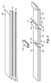
図1は、本開示に係る1つの例示の方法を示す。図2は、図1に示された方法を用いて作製される物理的多層フィルム構成体を模式的に示す。図1に示すように、バリアフィルム100は製造ラインに入る。第1主表面122上に第1ライナー及び第2主表面124上に第2ライナーを有する接着剤120(図1では感圧接着剤として示す)は、その第1ライナーが工程125において除去され、かつ第1主表面122がバリアフィルム100に隣接した状態でバリアフィルム100上に定置及び/又は積層される。接着剤120の第2ライナーは工程126において除去されて接着剤120の第2主表面124を暴露する。
FIG. 1 illustrates one exemplary method according to the present disclosure. FIG. 2 schematically shows a physical multilayer film construct made using the method shown in FIG. As shown in FIG. 1, the
次に、バリアフィルム/接着剤構成体はクロスウェブ方向に別個のセグメント130に切断され、かつバリアフィルム/接着剤構成体の一部分が除去されて(除去部分135)多層バリアフィルム100/接着剤120構成体の隣接した別個のセグメント130同士間に間隙140を形成する。いくつかの実施形態では、間隙は約3mm〜約2フィート(600mm)の範囲にある。いくつかの実施形態では、間隙は約15mm〜約200mmの範囲にある。いくつかの実施形態では、間隙はおよそ50mmである。
The barrier film / adhesive construct is then cut into
次に、バリアフィルム/接着剤構成体の除去部分135はダウンウェブ方向に保護層材料150で置き換えられ、これによって連続フィルムを再形成する。図1に示すように、これは次の通り行うことができる。保護層材料150のセグメントが間隙140にまたがり、かつバリアフィルム100/接着剤120構成体の2つの隣接した別個のセグメント130のそれぞれに接触するか又は重なるように、保護層材料150のセグメントが、バリアフィルム100/接着剤120構成体の2つの隣接した別個のセグメント130のそれぞれの上に定置される。いくつかの実施形態では、保護層150は第1末端エッジ152及び第2末端エッジ154を有し、かつエッジ(152及び154)はバリアフィルム100/接着剤120構成体の2つの隣接した別個のセグメント130の末端エッジ156及び158に接触する及び/又は重なる。
The
いくつかの実施形態では(例えば、図1及び図2に示したものも含む)、単一の保護層セグメント150はバリアフィルム100/接着剤120構成体の2つの隣接した別個のセグメント130のそれぞれに重なる。バリアフィルム100/接着剤120構成体の別個のセグメントと重なることによって、保護層セグメント150は連続材料のロールを形成するように巻き取ることができる材料の連続シートを形成する。保護層セグメント150はまた、バリアフィルム100/接着剤120構成体の別個のセグメント130の末端エッジ156及び158に対してエッジ保護をもたらす。
In some embodiments (including, for example, those shown in FIGS. 1 and 2), a single
いくつかの実施形態では、保護層150は、バリアフィルム100/接着剤120構成体と重なるところでは、該重なりは、バリアフィルム100/接着剤120構成体の各別個のセグメント130上に約1mm〜約50mmの範囲にすることができる。いくつかの実施形態では、該重なりは、バリアフィルム100/接着剤120構成体の各別個のセグメント130上に約5mm〜約20mmの範囲にある。いくつかの実施形態では、該重なりはバリアフィルム100/接着剤120構成体の各別個のセグメント130上に約10mmである。
In some embodiments, where the
いくつかの実施形態では、保護層150は、バリアフィルム100/接着剤120構成体の少なくとも部分に完全に重なる連続層である。このような実施形態では、保護層150は透明であってもよい。
In some embodiments, the
図1に示した最後の工程は、上述したように形成されたバリアフィルム100/接着剤120/保護層150構成体の上部に連続耐候性シート160(そのライナーは、存在していれば、除去されている)を定置すること及び/又は積層することである。その隣接したエッジが保護層150によって保護され、かつその上部表面(及びいくつかの実施形態では、サイドエッジ)が耐候性シート160によって保護される、バリア材料100の別個のセグメントを含む材料の連続シートは製造ラインから離れて、かつ販売することができるロールへ巻き取ることができる。熱ラミネーションはまた、図2に示した保護層セグメント150を接合する際に用いられてよい。
The last step shown in FIG. 1 is the
図1(及び図2)に示した特定の実施形態では、耐候性シート160はそれのダウンウェブ側面164及び166に沿ってエッジ保護材料180を含むように事前に処理されている。例えば、熱ラミネーションを介した接合を含む、取り付けの追加の方法を用いることができる。
In the particular embodiment shown in FIG. 1 (and FIG. 2),
上述した製造の利点に加えて、このプロセス及び結果得られる材料は、バリア材料の別個のセグメントをそれらの意図された最終用途のために所望のサイズに切断しておく、更に製造工程及びコストを低減するという付加的な利点を有する。 In addition to the manufacturing advantages described above, this process and the resulting material further cuts the separate segments of barrier material to the desired size for their intended end use, further reducing the manufacturing process and cost. Has the added advantage of reducing.
本開示のいくつかの実施形態は、バリアフィルムとして使用することができる連続多層フィルムに関する。図2及び図3は、本明細書に記載される方法に従って作製された連続フィルムの一部分の1つの代表的な物理的構成体を示す。図2は、加工中の連続フィルムバリア構成体の一部分を示す模式的、分解斜視図である。図3は、連続フィルムバリア構成体の一部分の断面図である。 Some embodiments of the present disclosure relate to continuous multilayer films that can be used as barrier films. 2 and 3 show one exemplary physical structure of a portion of a continuous film made according to the method described herein. FIG. 2 is a schematic, exploded perspective view showing a portion of the continuous film barrier construction being processed. FIG. 3 is a cross-sectional view of a portion of a continuous film barrier construction.
図3に示されている例示の構成体200は2つの別個のセグメント210及び220を含む。各セグメントはバリアフィルム100、接着剤120、及び基材240(図2には示されない)を含む。セグメント210及び220の上部に及びそれらに重なって、保護層セグメント150が存在する。保護層セグメント150は接着剤層120の第2主表面124に隣接している。図2及び図3に示されている特定の実施形態では、保護層150はポリマー層250(例えば、黒色ETFE)及び接着剤層260(例えば、感圧接着剤)を含む。保護層セグメント150の上部に及び重なって、耐候性シート160が存在する。図2及び図3に示されている実施形態では、耐候性シート160のダウンウェブ側面(164及び166)は、耐候性シート160のサイドエッジに沿って保護層材料180(ポリマー層270(例えば、黒色ETFE)及び接着剤層280(例えば、感圧接着剤)を含む)に隣接している。
The
図4及び図5は、概して本明細書に記載される方法及び教示に従って作製された1つの代表的な代替例示の構成体を示す。図4及び図5の組立品は、バリア層の隣接した別個のセグメントの末端エッジ同士の間に保護層セグメントを含まない。 4 and 5 generally illustrate one representative alternative exemplary construction made in accordance with the methods and teachings described herein. The assembly of FIGS. 4 and 5 does not include a protective layer segment between the end edges of adjacent separate segments of the barrier layer.
本明細書に記載される連続多層フィルムの単独層について以下により詳細に論じられる。 The single layers of the continuous multilayer film described herein are discussed in more detail below.
多層バリアフィルム
明細書において使用されるとき、用語「バリアフィルム」は酸素又は水の少なくとも一方に対してバリアを提供するフィルムを指す。バリアフィルムは、典型的には特定の用途によって要求されるような規定のレベルにおける酸素及び水透過率を有するように選択される。いくつかの実施形態では、バリアフィルムは、38℃及び100%相対湿度にて約0.005g/m2/日未満、いくつかの実施形態では、38℃及び100%相対湿度にて約0.0005g/m2/日未満、いくつかの実施形態では、38℃及び100%相対湿度にて0.00005g/m2/日未満の水蒸気透過率(WVTR)を有する。いくつかの実施形態では、バリアフィルムは50℃及び100%相対湿度で約0.05、0.005、0.0005、又は0.00005g/m2/日未満、又は更には85℃及び100%相対湿度で約0.005、0.0005、0.00005g/m2/日未満のWVTRを有する。いくつかの実施形態では、バリアフィルムは、23℃及び90%相対湿度で約0.005g/m2/日未満、いくつかの実施形態では、23℃及び相対湿度90%で約0.0005g/m2/日未満、いくつかの実施形態では、23℃及び90%相対湿度で0.00005g/m2/日未満の酸素透過率を有する。
Multilayer Barrier Film As used herein, the term “barrier film” refers to a film that provides a barrier to at least one of oxygen or water. The barrier film is typically selected to have oxygen and water permeability at a defined level as required by the particular application. In some embodiments, the barrier film is less than about 0.005 g / m 2 / day at 38 ° C. and 100% relative humidity, and in some embodiments, about 0.005 g at 38 ° C. and 100% relative humidity. Less than 0005 g / m 2 / day, in some embodiments, has a water vapor transmission rate (WVTR) of less than 0.00005 g / m 2 / day at 38 ° C. and 100% relative humidity. In some embodiments, the barrier film is less than about 0.05, 0.005, 0.0005, or 0.00005 g / m 2 / day, or even 85 ° C. and 100% at 50 ° C. and 100% relative humidity. It has a WVTR of less than about 0.005, 0.0005, 0.00005 g / m 2 / day at relative humidity. In some embodiments, the barrier film is less than about 0.005 g / m 2 / day at 23 ° C. and 90% relative humidity, and in some embodiments, about 0.0005 g / at 23 ° C. and 90% relative humidity. Less than m 2 / day, in some embodiments, has an oxygen transmission rate of less than 0.00005 g / m 2 / day at 23 ° C. and 90% relative humidity.
多層バリアフィルムは種々の構成体から選択することができる。いくつかの例示の有用な多層バリアフィルムは原子層蒸着、熱蒸発、スパッタリング、及び化学蒸着によって調製される無機フィルムを含む。いくつかの実施形態では、多層バリアフィルムは可撓性及び/又は透明である。 The multilayer barrier film can be selected from a variety of constructions. Some exemplary useful multilayer barrier films include inorganic films prepared by atomic layer deposition, thermal evaporation, sputtering, and chemical vapor deposition. In some embodiments, the multilayer barrier film is flexible and / or transparent.
いくつかの実施形態では、多層バリアフィルムは無機/有機多層を含む。無機/有機多層を含む可撓性超バリアフィルムは、例えば米国特許第7,018,713号(Padiyathら)に記載されている。このような可撓性超バリアフィルムは、第2ポリマー層により隔てられた、2つ以上の無機バリア層によりオーバーコートされたポリマーフィルム上に配設された第1ポリマー層を有してもよい。いくつかの実施形態では、バリアフィルムは第1ポリマー層上に介在する1つ無機酸化物を含む。追加の代表的な多層バリアフィルムはまた、例えば米国特許第4,696,719号(Bischoff)、同第4,722,515号(Ham)、同第4,842,893号(Yializisら)、同第4,954,371号(Yializis)、同第5,018,048号(Shawら)、同第5,032,461号(Shawら)、同第5,097,800号(Shawら)、同第5,125,138号(Shawら)、同第5,440,446号(Shawら)、同第5,547,908号(Furuzawaら)、同第6,045,864号(Lyonsら)、同第6,231,939号(Shawら)及び第6,214,422号(Yializis)において;公開済みPCT出願第WO 00/26973号(Delta V Technologies,Inc.)において;D.G.Shaw及びM.G.Langlois,「A New Vapor Deposition Process for Coating Paper and Polymer Webs」,6th International Vacuum Coating Conference(1992)において;D.G.Shaw及びM.G.Langlois、「A New High Speed Process for Vapor Depositing Acrylate Thin Films:An Update」、Society of Vacuum Coaters 36th Annual Technical Conference Proceedings(1993)において;D.G.Shaw及びM.G.Langlois、「Use of Vapor Deposited Acrylate Coatings to Improve the BarrierProperties of Metallized Film」、Society of Vacuum Coaters 37th Annual Technical Conference Proceedings(1994)において;D.G.Shaw,M.Roehrig,M.G.Langlois and C.Sheehan、「Use of Evaporated Acrylate Coatings to Smooth the Surface of Polyester and Polypropylene Film Substrates」、RadTech(1996)において;J.Affinito,P.Martin,M.Gross,C.Coronado及びE.Greenwell、「Vacuum deposited polymer/metal multilayer films for optical application」、Thin Solid Films 270、43〜48(1995)において;及びJ.D.Affinito,M.E.Gross,C.A.Coronado,G.L.Graff,E.N.Greenwell and P.M.Martin、「Polymer−Oxide Transparent Barrier Layers」において見出すことができる。1つの代表的な市販のバリアフィルムは、3M Companyから市販されているUBF 9Lである。
In some embodiments, the multilayer barrier film comprises an inorganic / organic multilayer. Flexible super-barrier films containing inorganic / organic multilayers are described, for example, in US Pat. No. 7,018,713 (Padiyath et al.). Such a flexible super-barrier film may have a first polymer layer disposed on a polymer film overcoated with two or more inorganic barrier layers separated by a second polymer layer. . In some embodiments, the barrier film includes one inorganic oxide interposed on the first polymer layer. Additional exemplary multilayer barrier films are also described, for example, in U.S. Pat. Nos. 4,696,719 (Bischoff), 4,722,515 (Ham), 4,842,893 (Yializis et al.), 4,954,371 (Yializis), 5,018,048 (Shaw et al.), 5,032,461 (Shaw et al.), 5,097,800 (Shaw et al.) 5,125,138 (Shaw et al.), 5,440,446 (Shaw et al.), 5,547,908 (Furuzawa et al.), 6,045,864 (Lyons). Et al., 6,231,939 (Shaw et al.) And 6,214,422 (Yializis); published PCT application WO 00/26973 (Delta). V Technologies, in Inc);. D. G. Shaw and M.W. G. Langlois, “A New Vapor Deposition Process for Coating Paper and Polymer Webs”, 6th International Vacuum Coating Conference (1992); G. Shaw and M.W. G. Langlois, “A New High Speed Process for Vapor Depositing Acrylate Thin Films: An Update”, Society of Proceeds of Water Coats. G. Shaw and M.W. G. Langlois, “Use of Vapor Deposited Acrylate Coatings to Improve the Barrier Properties of Metalized Film 94, Society of Vaccum Coates 37”. G. Shaw, M .; Roehrig, M.C. G. Langlois and C.L. In Sheehan, “Use of Evaporated Coatings to Smooth the Surface of Polyester and Polypropylene Film Substrates”, RadTech (1996); Affinito, P.A. Martin, M.M. Gross, C.I. Coronado and E.I. Greenwell, “Vacuum deposited polymer / metal multilayer film for optical application,” Thin
いくつかの実施形態では、多層バリアフィルムは環境から絶縁されている。本出願の目的で、バリアフィルムは、組立品を取り囲む空気との境界面を有しないときには、「環境から絶縁されている」。 In some embodiments, the multilayer barrier film is insulated from the environment. For the purposes of this application, a barrier film is “insulated from the environment” when it does not have an interface with the air surrounding the assembly.
基材を含む実施形態において、並びにバリアフィルムと基材が互いに直接に隣接している場合には、基材の主表面は、バリアフィルムへの粘着力を向上させるように、処理することができる。いくつかの代表的な表面処理としては、好適な反応性又は非反応性雰囲気(例えば、プラズマ、グロー放電、コロナ放電、誘電体バリア放電又は大気圧放電)の存在下での電気放電;化学前処理;又は火炎前処理が挙げられる。いくつかの実施形態は、基材の主表面とバリアフィルムとの間にやはり形成され得る別個の粘着力促進層を含む。粘着力促進層は、例えば別個のポリマー層又は金属、金属酸化物、金属窒化物、あるいは金属酸窒化物の層などの金属含有層とすることができる。いくつかの実施形態では、粘着力促進層は数ナノメートル(nm)(例えば、1又は2nm)から約50nm以上までの厚さを有する。いくつかの実施形態では、基材の一方の面(つまり、一方の主表面)はバリアフィルムへの粘着力を向上させるように処理することができる、かつ他方の面(つまり、主表面)は被覆されるべきデバイス又はこのようなデバイスを被覆する封止材(例えば、EVA又はポリオレフィン)への粘着力を向上させるように処理することができる。(例えば、溶剤又は他の前処理により)表面処理された一部の有用な基材は、例えばDu Pont Teijin社から市販されている。これらのフィルムの一部に対しては、両面が表面処理され(例えば、同一又は異なる前処理により),他のフィルムに対しては、片面のみが表面処理される。 In embodiments that include a substrate, and when the barrier film and the substrate are directly adjacent to each other, the major surface of the substrate can be treated to improve adhesion to the barrier film. . Some typical surface treatments include electrical discharges in the presence of a suitable reactive or non-reactive atmosphere (eg, plasma, glow discharge, corona discharge, dielectric barrier discharge or atmospheric pressure discharge); Treatment; or flame pretreatment. Some embodiments include a separate adhesion promoting layer that can also be formed between the major surface of the substrate and the barrier film. The adhesion promoting layer can be, for example, a separate polymer layer or a metal-containing layer such as a metal, metal oxide, metal nitride, or metal oxynitride layer. In some embodiments, the adhesion promoting layer has a thickness from a few nanometers (nm) (eg, 1 or 2 nm) to about 50 nm or more. In some embodiments, one side of the substrate (ie, one major surface) can be treated to improve adhesion to the barrier film, and the other side (ie, the major surface) is It can be treated to improve the adhesion to the device to be coated or the encapsulant (eg EVA or polyolefin) covering such a device. Some useful substrates that have been surface treated (eg, with solvents or other pretreatments) are commercially available from, for example, Du Pont Teijin. For some of these films, both sides are surface treated (eg, by the same or different pretreatments), and for other films, only one side is surface treated.
いくつかの実施形態では、多層バリアフィルムは可視光及び赤外光に対して透過性である。用語「可視光及び赤外光に対して透過性」は、本明細書で使用するとき、スペクトルの可視及び赤外部分にわたって垂直軸に沿って測定した少なくとも約75%の平均透過率を有することを意味する。いくつかの実施形態では、可視光及び赤外線透過性組立品は、400nm〜1400nmの範囲の平均透過率が少なくとも約75%(いくつかの実施形態では少なくとも約80、85、90、92、95、97又は98%)である。可視光及び赤外線透過性組立品は、例えば光電池による、可視光及び赤外線の吸収に関して干渉しないものである。いくつかの実施形態では、可視光及び赤外線透過性組立品は、光電池に有用である光の波長の範囲の平均透過率が少なくとも約75%(いくつかの実施形態では少なくとも約80、85、90、92、95、97又は98%)である。 In some embodiments, the multilayer barrier film is transparent to visible light and infrared light. The term “transparent to visible and infrared light” as used herein has an average transmission of at least about 75% measured along the vertical axis over the visible and infrared portions of the spectrum. Means. In some embodiments, the visible and infrared transmissive assembly has an average transmission in the range of 400 nm to 1400 nm of at least about 75% (in some embodiments at least about 80, 85, 90, 92, 95, 97 or 98%). Visible and infrared transmissive assemblies are those that do not interfere with the absorption of visible and infrared light, eg, by a photovoltaic cell. In some embodiments, the visible and infrared transmissive assembly has an average transmittance of at least about 75% (in some embodiments at least about 80, 85, 90) in the range of wavelengths of light useful for photovoltaic cells. 92, 95, 97 or 98%).
いくつかの実施形態では、多層バリアフィルムは可撓性である。本明細書で使用するとき、用語「可撓性」は、ロールに成形することができることを指す。いくつかの実施形態では、用語「可撓性」は、最大7.6センチメートル(cm)(3インチ)の曲率半径でロール芯の周りに折り曲げることができることを指す。いくつかの実施形態は、最大(6.4cm)(2.5インチ)、5cm(2インチ)、3.8cm(1.5インチ)、又は2.5cm(1インチ)曲率半径を有する。いくつかの実施形態では、可撓性組立品は少なくとも0.635cm(1/4インチ)、1.3cm(1/2インチ)又は1.9cm(3/4インチ)の曲率半径の周りに折り曲げることができる。 In some embodiments, the multilayer barrier film is flexible. As used herein, the term “flexible” refers to being able to be formed into a roll. In some embodiments, the term “flexible” refers to being able to fold around a roll core with a radius of curvature of up to 7.6 centimeters (cm) (3 inches). Some embodiments have a radius of maximum (6.4 cm) (2.5 inches), 5 cm (2 inches), 3.8 cm (1.5 inches), or 2.5 cm (1 inch). In some embodiments, the flexible assembly folds around a radius of curvature of at least 1/4 inch, 1.3 cm (1/2 inch), or 1.9 cm (3/4 inch). be able to.
保護層
保護層は、可視光線(380〜750nm)がバリアフィルムに到達することを妨げる任意の層とすることができる。いくつかの実施形態では、保護層は不透明である。本出願の目的で、層が可視光(380〜750nm)の透過率の低減をもたらすならば、具体的には380〜450nmの間に透過率を低減させるならば、その層は不透明であり、これによって可視光がバリアフィルムに到達するのを妨げる。一般的に、層の追加が多層フィルムにおいて、380〜450nmの間の任意の波長で最大20%の透過率を生じる場合に、層は不透明である。いくつかの実施形態では、不透明層は380〜450nmの間の任意の波長で2%透過の最大透過率を生じる。特定の実施形態において、不透明層は、380〜450nmの間のいずれかの波長において、0.2%の最大透過率を形成する。実施例はインク層(例えば、油性マーカーからのインク)及び不透明テープを含む。1つの例示の特定の実施例は、Asahi Glass Ltd.(Tokyo,Japan)から市販されている黒色ETFE(例えば、ETFE(エチレンテトラフルオロエチレン)の裏材を有し、かつ3M Companyから市販されている8172PCLなどのPSAを使用して積層される不透明テープである。いくつかの実施形態では、裏材は3M Companyから市販されている3M Tape Primer 94などの接着剤層と反対側のプライマーを含んでもよい。不透明保護層が不透明テープである場合、テープは多層フィルム内のいずれかの向きにあり得る。例えば、テープは、電子デバイスと反対側のバリアフィルムフィルム上にあり得る。テープはまた、電子デバイスの反対側、又は電子デバイスと同じ側のいずれかの、耐候性シート上にあり得る。このような実施形態では、テープは電子デバイスと同じ側にある、不透明テープは耐候性シートによって被覆することができ、不透明テープのために付加的保護度が提供される。
Protective layer The protective layer can be any layer that prevents visible light (380-750 nm) from reaching the barrier film. In some embodiments, the protective layer is opaque. For the purposes of this application, if a layer results in a reduction in the transmission of visible light (380-750 nm), specifically if the transmission is reduced between 380-450 nm, the layer is opaque; This prevents visible light from reaching the barrier film. In general, a layer is opaque when the addition of the layer results in a multilayer film that produces up to 20% transmission at any wavelength between 380 and 450 nm. In some embodiments, the opaque layer produces a maximum transmission of 2% transmission at any wavelength between 380 and 450 nm. In certain embodiments, the opaque layer forms a maximum transmission of 0.2% at any wavelength between 380 and 450 nm. Examples include ink layers (eg, ink from oily markers) and opaque tape. One illustrative specific example is Asahi Glass Ltd. Opaque tape with a black ETFE (eg, ETFE (ethylene tetrafluoroethylene) backing available from Tokyo, Japan) and laminated using a PSA such as 8172PCL available from 3M Company In some embodiments, the backing may include a primer opposite the adhesive layer, such as 3M Tape Primer 94 commercially available from 3M Company, where the tape is when the opaque protective layer is an opaque tape. Can be in any orientation within the multilayer film, for example, the tape can be on the barrier film film opposite the electronic device, either on the opposite side of the electronic device, or on the same side as the electronic device. In such an embodiment, in such an embodiment, the Flop is on the same side as the electronic device, the opaque tape may be coated with weather resistant sheet, additional protection degree for the opaque tape is provided.
保護層は任意の所望の長さ及び幅とすることができる。いくつかの実施形態では、保護層は組立品の周縁部に定置されてよい、若しくは組立品の表面の周りにフレームを形成することができる。エッジに集中する応力が原因で、層間剥離は、概して、エッジ内に又は周りに開始しやすい。いったん層間剥離が始まると、「エッジ」は多層物品の反対側に向けて前進して、その結果、層同士間の界面全体の層間剥離が生じることになる。エッジにおける層間剥離を停止することによって、多層物品における単独層が接着されたままであることを可能にする。 The protective layer can be of any desired length and width. In some embodiments, the protective layer may be placed on the periphery of the assembly or may form a frame around the surface of the assembly. Due to the stress concentrated at the edge, delamination generally tends to start in or around the edge. Once delamination begins, the “edge” advances toward the opposite side of the multilayer article, resulting in delamination across the interface between the layers. By stopping delamination at the edges, it is possible for a single layer in the multilayer article to remain adhered.
いくつかの実施形態では、ソーラーモジュール全体に入射する光は表面積の少なくとも一部分に、例えば5%未満、1%未満あるいは0.5%未満に制限される。光は連続的に又は不連続パターン、例えば点、線、記号、文字、数、あるいは図形において遮断できる。また、組立品の周縁部に光の遮断、すなわち組立品の表面の周りに光の透過を制限するフレームを作成することは有益であり得る。 In some embodiments, light incident on the entire solar module is limited to at least a portion of the surface area, for example, less than 5%, less than 1%, or less than 0.5%. The light can be blocked in a continuous or discontinuous pattern, such as dots, lines, symbols, letters, numbers, or figures. It may also be beneficial to create a frame at the periphery of the assembly that blocks light, i.e., restricts light transmission around the surface of the assembly.
いくつかの実施形態では、保護層は、インク層、金属箔層、及び無機バリア層などの無金属のバリア層のうちの少なくとも1つを含む。任意の金属箔層を使用することができる。いくつかの実施形態では、金属箔はアルミホイルである。1つの商業的に代表的なアルミホイルがAll Foils,Inc.によって販売されている。金属の高コスト化を招くことなく、水に対するバリアを生成することができるいかなる無機層も使用することができる。光を遮断するいかなるインク層も使用することができる。 In some embodiments, the protective layer includes at least one of a metal-free barrier layer such as an ink layer, a metal foil layer, and an inorganic barrier layer. Any metal foil layer can be used. In some embodiments, the metal foil is an aluminum foil. One commercially representative aluminum foil is All Foils, Inc. Sold by. Any inorganic layer that can create a barrier to water without incurring high metal costs can be used. Any ink layer that blocks light can be used.
図2及び図3は本開示に係るいくつかの例示の実施形態を示す。図2及び図3では、不透明保護層はバリア層の各別個のセグメントの周縁部を完全に取り囲む。 2 and 3 illustrate some exemplary embodiments according to the present disclosure. 2 and 3, the opaque protective layer completely surrounds the peripheral edge of each separate segment of the barrier layer.
耐候性シート
本開示のいくつかの実施形態は耐候性シートを含む。耐候性シートは単層にでも多層にでもできる。いくつかの実施形態では、耐候性シートは可撓性及び/又は可視光と赤外光に対して透過性であり、かつ/又は有機フィルム形成ポリマーを含む。耐候性シートを形成することができるいくつかの代表的な材料は、ポリエステル、ポリカーボネート、ポリエーテル、ポリイミド、ポリオレフィン、フルオロポリマー、及びこれらの組み合わせを含む。
Weatherproof Sheet Some embodiments of the present disclosure include a weatherproof sheet. The weatherproof sheet can be a single layer or multiple layers. In some embodiments, the weatherable sheet is flexible and / or transmissive to visible and infrared light and / or includes an organic film-forming polymer. Some exemplary materials that can form a weatherproof sheet include polyester, polycarbonate, polyether, polyimide, polyolefin, fluoropolymer, and combinations thereof.
電子デバイスが、例えばソーラーデバイスである実施形態では、耐候性シートが紫外(UV)線による劣化に対して耐性があることが望ましい。紫外線(例えば、約280〜約400nmの波長を有する光)により引き起こされる光酸化分解は、ポリマーフィルムの変色並びに光学的及び機械的特性の低下につながるおそれがある。本明細書に記載の耐候性シートは、例えば光起電デバイスのための耐性、耐候性トップコートを提供することができる。基材は、通常、耐摩耗性及び衝撃耐性であり、例えば屋外要素に曝露した際の光起電デバイスの劣化を防止することができる。 In embodiments where the electronic device is a solar device, for example, it is desirable for the weatherable sheet to be resistant to degradation by ultraviolet (UV) radiation. Photo-oxidative degradation caused by ultraviolet light (eg, light having a wavelength of about 280 to about 400 nm) can lead to discoloration of the polymer film and degradation of optical and mechanical properties. The weatherable sheets described herein can provide a resistant, weatherable topcoat, for example, for photovoltaic devices. The substrate is typically abrasion and impact resistant and can prevent degradation of the photovoltaic device, for example when exposed to outdoor elements.
UV光への耐性を改善するために、耐候性シートに各種の安定剤を添加することができる。このような安定剤の具体例は、紫外線吸収剤(UVA)(例えば、赤色シフトUV吸収剤)、ヒンダードアミン光安定剤(HALS)、及び/又抗酸化剤のうちの少なくとも1つを含む。これらの添加剤は、下記に更に詳細に説明される。いくつかの実施形態では、用語「紫外光による劣化に対して抵抗性である」は、耐候性シートが少なくとも1つの紫外線吸収剤又はヒンダードアミン光安定剤を含むことを意味する。いくつかの実施形態では、用語「紫外光による劣化に対して耐性」は、耐候性シートが、少なくとも300nm〜400nmの波長範囲において少なくとも30nm範囲にわたって入射紫外光の少なくとも50%を反射又は吸収することを意味する。いくつかの実施形態では、耐候性シートはUVA又はHALSを含む必要がない。 In order to improve the resistance to UV light, various stabilizers can be added to the weather-resistant sheet. Specific examples of such stabilizers include at least one of an ultraviolet absorber (UVA) (eg, a red shift UV absorber), a hindered amine light stabilizer (HALS), and / or an antioxidant. These additives are described in further detail below. In some embodiments, the term “resistant to ultraviolet light degradation” means that the weatherable sheet comprises at least one UV absorber or hindered amine light stabilizer. In some embodiments, the term “resistant to degradation by ultraviolet light” means that the weathering sheet reflects or absorbs at least 50% of incident ultraviolet light over a range of at least 30 nm in a wavelength range of at least 300 nm to 400 nm. Means. In some embodiments, the weatherable sheet need not include UVA or HALS.
耐候性シートのUV耐久性は、例えば加速耐候性試験を用いて評価可能である。加速耐候試験は、概して、ASTM G−155「Standard practice for exposing non−Metallic materias in accelerated test devices that use laboratory light sources」に記載されるものと同様の技法を使用して、フィルム上で行なわれる。上記のASTMの方法は、材料性能を正しくランク付けする、屋外耐久性の妥当な予測因子と考えられる。物理的特性の変化を検出するための機構は、ASTM G155において説明される耐候サイクル及び反射モードで操作されるD65光源の使用である。上記試験下で、紫外線保護層が物品に適用される場合、物品は、著しい亀裂、剥離、層間剥離又は曇りの発生前、CIE L*a*b*色空間を使用して得られるb*値が、5以下、4以下、3以下、又は2以下で増加する前に、340nmにおいて少なくとも18,700kJ/m2の曝露に耐えなければならない。 The UV durability of the weather resistant sheet can be evaluated using, for example, an accelerated weather resistance test. Accelerated weathering is generally performed as described in ASTM G-155 “Standard practice for exposing non-Metallic materials in accredited test devices that use laboratory light sources”. The ASTM method described above is considered a reasonable predictor of outdoor durability that ranks material performance correctly. A mechanism for detecting changes in physical properties is the use of a D65 light source operated in the weathering cycle and reflection mode described in ASTM G155. Under the above test, when the UV protective layer is applied to the article, the article will be b * value obtained using CIE L * a * b * color space before the occurrence of significant cracks, delamination, delamination or haze. Must withstand an exposure of at least 18,700 kJ / m 2 at 340 nm before increasing below 5, 4 below, 3 below, or 2 below.
いくつかの実施形態において、本明細書に開示された耐候性シートは、フルオロポリマーを含む。フルオロポリマーは、典型的には、UVA、HALS及び酸化防止剤などの安定剤がない場合でも、UV分解に対して耐性である。いくつかの代表的なフルオロポリマーは、エチレン−テトラフルオロエチレンコポリマー(ETFE)、エチレン−クロロ−トリフルオロエチレンコポリマー(ECTFE)、テトラフルオロエチレン−ヘキサフルオロプロピレンコポリマー(FEP)、テトラフルオロエチレン−ペルフルオロビニルエーテルコポリマー(PFA,MFA)テトラフルオロエチレン−ヘキサフルオロプロピレン−フッ化ビニリデンコポリマー(THV)、ポリフッ化ビニリデンホモ及びコポリマー(PVDF)、これらのブレンド、及びこれらの及びその他のフルオロポリマーのブレンドを含む。フルオロポリマーは、典型的には、TFE、CTFE、VDF、HFPのホモ又はコポリマー若しくは他の十分にフッ素化された、部分的フッ素化された若しくはビニルエーテル及びアルファ−オレフィン又は他のハロゲン含有モノマーなどの水素添加モノマーを含む。 In some embodiments, the weatherable sheet disclosed herein comprises a fluoropolymer. Fluoropolymers are typically resistant to UV degradation even in the absence of stabilizers such as UVA, HALS and antioxidants. Some representative fluoropolymers are ethylene-tetrafluoroethylene copolymer (ETFE), ethylene-chloro-trifluoroethylene copolymer (ECTFE), tetrafluoroethylene-hexafluoropropylene copolymer (FEP), tetrafluoroethylene-perfluorovinyl ether. Copolymer (PFA, MFA) tetrafluoroethylene-hexafluoropropylene-vinylidene fluoride copolymer (THV), polyvinylidene fluoride homo and copolymer (PVDF), blends thereof, and blends of these and other fluoropolymers. Fluoropolymers are typically TFE, CTFE, VDF, HFP homo- or copolymers or other fully fluorinated, partially fluorinated or vinyl ether and alpha-olefins or other halogen containing monomers, etc. Contains hydrogenated monomers.
フルオロポリマーフィルムのCTEは、典型的には、炭化水素ポリマーから作製されるフィルムと比較して大きい。例えば、フルオロポリマーフィルムのCTEは、少なくとも75、80、90、100、110、120、又は130ppm/K(150、160、180、200、220、240又は260ppm/℃)であってよい。例えば、ETFEのCTEは、90〜140ppm/K(180〜280ppm℃)の範囲であってよい。 The CTE of fluoropolymer films is typically large compared to films made from hydrocarbon polymers. For example, the CTE of the fluoropolymer film may be at least 75, 80, 90, 100, 110, 120, or 130 ppm / K (150, 160, 180, 200, 220, 240, or 260 ppm / ° C.). For example, the CTE of ETFE may be in the range of 90-140 ppm / K (180-280 ppm ° C.).
基材が少なくとも1種のフルオロポリマーを含む実施形態では、基材及び/又はフィルムはまた非フッ素化材料を含む。例えば、ポリフッ化ビニリデンとポリメチルメタクリレートの配合物を使用することができる。いくつかの代表的な可撓性、可視光・赤外光透過性基材は多層フィルム基材を含む。多層フィルム基材は、異なる層に異なるフルオロポリマーを有することができ、又は少なくとも1層のフルオロポリマー及び少なくとも1層の非フッ素化ポリマーを含むことができる。多層フィルムは、数層(例えば、少なくとも2又は3層)を含むか、又は少なくとも100層(例えば、全層で100〜2000又はそれ以上の範囲の)を含むことができる。異なる多層フィルム基材における異なるポリマーは、例えば米国特許第5,540,978号(Schrenk)に記載されるように、例えば300〜400nmの波長範囲においてUV光の相当部分(例えば、少なくとも30、40、又は50%)を反射するように選択することができる。このようなブレンド及び多層フィルム基材は、上述のフルオロポリマーよりも低いCTEを有する耐UV性基材を提供するのに有用であり得る。 In embodiments where the substrate includes at least one fluoropolymer, the substrate and / or film also includes a non-fluorinated material. For example, a blend of polyvinylidene fluoride and polymethyl methacrylate can be used. Some exemplary flexible, visible / infrared light transmissive substrates include multilayer film substrates. The multilayer film substrate can have different fluoropolymers in different layers, or can comprise at least one fluoropolymer and at least one non-fluorinated polymer. Multilayer films can include several layers (eg, at least 2 or 3 layers) or at least 100 layers (eg, in the range of 100 to 2000 or more in all layers). Different polymers in different multi-layer film substrates can be represented by a substantial portion of UV light (eg, at least 30, 40, for example, in the wavelength range of 300-400 nm, as described in US Pat. No. 5,540,978 (Schrenk). , Or 50%). Such blends and multilayer film substrates can be useful in providing UV resistant substrates having a lower CTE than the fluoropolymers described above.
フルオロポリマーを含む有用な耐候性シートは、例えば、商品名「TEFZEL ETFE」及び「TEDLAR」でE.I.DuPont De Nemours and Co.,Wilmington,DEから商業的に入手することができる、かつフィルムは商品名「DYNEON ETFE」、「DYNEON THV」、「DYNEON FEP」、及び「DYNEON PVDF」でDyneon LLC,Oakdale,MNから、商品名「NORTON ETFE」でSt.Gobain Performance Plastics,Wayne,NJから、商品名「CYTOPS」でAsahi Glass Ltd.から、並びに商品名「DENKA DX FILM」でDenka Kagaku Kogyo KK,Tokyo,Japanから入手可能な樹脂から作製される。 Useful weathering sheets comprising fluoropolymers are available, for example, under the trade names “TEFZEL ETFE” and “TEDLAR” from E.I. I. DuPont De Nemours and Co. , Commercially available from Wilmington, DE, and films are trade names from Dyneon LLC, Oakdale, MN under the trade names "DYNEON ETFE", "DYNEON THV", "DYNEON FEP", and "DYNEON PVDF". “NORTON ETFE” Asahi Glass Ltd. under the trade name “CYTOPS” from Gobain Performance Plastics, Wayne, NJ. And from the resin available from Denka Kagaku Kogyo KK, Tokyo, Japan under the trade name “DENKA DX FILM”.
フルオロポリマーを含まないいくつかの代表的な耐候性シートは、UVA、HALS、及び抗酸化剤の不在化でUV光による分解に対して耐性があると報告されている。例えば、米国特許第3,444,129号;同第3,460,961号;同第3,492,261号;及び同第3,503,779号に記載されているものなど、例えばある特定のレゾルシノールイソフタル酸/テレフタル酸コポリアリーレートは耐候性であると報告されている。1,3−ジヒドロキシベンゼン有機ジカルボン酸塩由来の構造単位を備える層を含有するある特定の耐候性多層物品は国際特許出願公開第WO 2000/061664号に報告されている、かつレゾルシノールアリレートポリエステル鎖成分を含有するある特定のポリマーが米国特許第6,306,507号に報告されている。少なくとも1種の1,3−ジヒドロキシベンゼンと少なくとも1種の芳香族ジカルボン酸に由来する構造単位を備え、1つの層に形成され、かつ炭酸塩構造単位を備える別のポリマーと積層された、ブロックコポリエステル炭素塩が米国特許公開第2004/0253428号に報告されている。ポリカーボネートを含有する耐候性シートは、例えばポリエステルと比較して比較的大きいCTEを有することがある。ポリカーボネートを含有する耐候性シートのCTEは、例えば約70ppm/K(140ppm/℃)であってよい。 Some representative weatherproof sheets that do not contain a fluoropolymer have been reported to be resistant to degradation by UV light in the absence of UVA, HALS, and antioxidants. For example, certain ones such as those described in US Pat. Nos. 3,444,129; 3,460,961; 3,492,261; and 3,503,779 Of resorcinol isophthalic acid / terephthalic acid copolyarylate are reported to be weather resistant. Certain weatherable multilayer articles containing layers comprising structural units derived from 1,3-dihydroxybenzene organic dicarboxylate are reported in International Patent Application Publication No. WO 2000/061664, and resorcinol arylate polyester chain component Certain polymers containing are reported in US Pat. No. 6,306,507. A block comprising structural units derived from at least one 1,3-dihydroxybenzene and at least one aromatic dicarboxylic acid, laminated in one layer and laminated with another polymer comprising carbonate structural units Copolyester carbon salts are reported in US Patent Publication No. 2004/0253428. Weatherproof sheets containing polycarbonate may have a relatively large CTE compared to, for example, polyester. The CTE of the weatherable sheet containing polycarbonate may be, for example, about 70 ppm / K (140 ppm / ° C.).
上記の耐候性シートの実施形態のいずれのためにでも、耐候性シート(例えば、フルオロポリマー)の主表面は感圧接着剤との密着性を向上させるために処理を施すことができる。有用な表面処理としては、好適な反応性又は非反応性雰囲気(例えば、プラズマ、グロー放電、コロナ放電、誘電体バリア放電又は大気圧放電)の存在における電気的な放電;化学的前処理(例えば、アルカリ溶液及び/又は液体アンモニアを用いる);火焔前処理;又は電子線ビーム処理が挙げられる。更に別個の接着促進層を耐候性シートの主表面と感圧接着剤(PSA)との間に形成することもできる。いくつかの実施形態では、耐候性シートは基材と感圧接着剤との間に化学結合を形成するためにPSAで塗布され、かつ引き続いて電子ビームで照射されたフルオロポリマーであってもよい;(例えば、米国特許第6,878,400号(Yamanakaら)を参照)。表面処理される一部の有用な耐候性シートは、例えば商品名「NORTON ETFE」でSt.Gobain Performance Plasticsから市販されている。 For any of the above weather resistant sheet embodiments, the main surface of the weather resistant sheet (eg, fluoropolymer) can be treated to improve adhesion to the pressure sensitive adhesive. Useful surface treatments include electrical discharges in the presence of a suitable reactive or non-reactive atmosphere (eg plasma, glow discharge, corona discharge, dielectric barrier discharge or atmospheric pressure discharge); chemical pretreatment (eg , Alkaline solution and / or liquid ammonia); flame pretreatment; or electron beam treatment. Furthermore, a separate adhesion promoting layer can be formed between the main surface of the weatherproof sheet and the pressure sensitive adhesive (PSA). In some embodiments, the weatherable sheet may be a fluoropolymer applied with PSA to form a chemical bond between the substrate and the pressure sensitive adhesive and subsequently irradiated with an electron beam. (See, eg, US Pat. No. 6,878,400 (Yamanaka et al.)). Some useful weather-resistant sheets that are surface treated are, for example, St. Commerce under the trade name “NORTON ETFE”. Commercially available from Gobain Performance Plastics.
いくつかの実施形態で耐候性シートは、約0.01mm〜約1mm、いくつかの実施形態では約0.05mm〜約0.25mm又は0.05mm〜0.15mmの厚さを有する。 In some embodiments, the weatherable sheet has a thickness of about 0.01 mm to about 1 mm, and in some embodiments about 0.05 mm to about 0.25 mm, or 0.05 mm to 0.15 mm.
接着剤
既知の接着剤が使用できる。いくつかの実施形態では、感圧接着剤(「PSA」)は耐候性シートとバリアフィルムとの間にある。PSAは、(1)侵襲性及び永続性のある粘着、(2)指圧以下の圧力による接着力、(3)被着体に貼り続ける充分な能力、及び(4)被着体からきれいに取り外すのに充分な凝集力さを含む特性を有することが、当業者には周知である。PSAとして良好に機能することが分かっている材料は、必要な粘弾性特性を示し、粘着、剥離接着、及び剪断保持力の所望のバランスをもたらすように設計並びに処方されたポリマーである。1つの代表的な市販の接着剤は、3M Companyにより販売される、8172PCLである。
Adhesives Known adhesives can be used. In some embodiments, the pressure sensitive adhesive (“PSA”) is between the weatherable sheet and the barrier film. PSA has (1) invasive and permanent adhesion, (2) adhesive strength by pressure below finger pressure, (3) sufficient ability to continue to adhere to the adherend, and (4) clean removal from the adherend. Are well known to those skilled in the art. Materials that have been shown to function well as PSA are polymers that are designed and formulated to exhibit the necessary viscoelastic properties and provide the desired balance of tack, peel adhesion, and shear retention. One representative commercially available adhesive is 8172 PCL, sold by 3M Company.
感圧接着剤を識別するための有用な1つの方法は、Dahlquist基準である。この基準は感圧接着剤を、1×10⁻⁶cm2/ダイン(1×10−5m2/N)を上回る1秒クリープコンプライアンスを有する接着剤と定義している。これは「Handbook of Pressure Sensitive Adhesive Technology」,Donatas Satas(Ed.),2nd Edition,p.172,Van Nostrand Reinhold,New York,NY,1989に記載されており、本明細書に参照によって組み込まれている。別の方法としては、弾性率が、第1の近似により、クリープコンプライアンスの逆数であるので、感圧接着剤は約1×10⁶ダイン/cm2(1×105Pa)未満の貯蔵弾性率を有する接着剤と定義されてよい。 One useful method for identifying pressure sensitive adhesives is the Dahlquist criterion. This criterion defines a pressure sensitive adhesive as an adhesive having a 1 second creep compliance of greater than 1 × 10 −6 cm 2 / dyne (1 × 10 −5 m 2 / N). This is "Handbook of Pressure Sensitive Adhesive Technology", Donatas Satas (Ed.), 2 nd Edition, p. 172, Van Nostrand Reinhold, New York, NY, 1989, which is incorporated herein by reference. Alternatively, the elastic modulus is the reciprocal of creep compliance, according to the first approximation, so that the pressure sensitive adhesive has a storage modulus less than about 1 × 10 6 dynes / cm 2 (1 × 10 5 Pa). May be defined as an adhesive having
いくつかの実施形態では、PSAは流動しない、かつ接着剤結合ラインを通しての酸素及び水分の遅い又は最小湿潤を提供するのに十分なバリア特性を有する。また、いくつかの実施形態では、PSAは、概して、例えば光起電力セルによる可視光の吸収を妨害しないように、可視光と赤外光に対して透過性である,.PSAは、垂直軸に沿って測定すると、スペクトルの可視部分にわたって少なくとも約75%(いくつかの実施形態では、少なくとも約80、85、90、92、95、97又は98%)の平均透過率を有する。いくつかの実施形態では、PSAは、400nm〜1400nmの範囲にわたって少なくとも約75%(いくつかの実施形態では少なくとも約80、85、90、92、95、97又は98%)の平均透過率を有する。代表的なPSAとしては、アクリレート、シリコーン、ポリイソブチレン、尿素及びこれらの組み合わせが挙げられる。一部の有用な市販のPSAとしては、商品名「ARclear 90453」及び「ARclear 90537」でペンシルベニア州Glen RockのAdhesive Research,Inc.社から入手可能なものなどの紫外線硬化性PSA、並びに商品名「OPTICALLY CLEAR LAMINATING ADHESIVE 8171」、「OPTICALLY CLEAR LAMINATING ADHESIVE 8172CL」及び「OPTICALLY CLEAR LAMINATING ADHESIVE 8172PCL」でミネソタ州St.Paulの3M Company社から入手可能な光学的に透明なPSAが挙げられる。 In some embodiments, the PSA does not flow and has sufficient barrier properties to provide slow or minimal wetting of oxygen and moisture through the adhesive bond line. Also, in some embodiments, the PSA is generally transmissive to visible and infrared light so as not to interfere with the absorption of visible light by, for example, photovoltaic cells. The PSA has an average transmission of at least about 75% (in some embodiments, at least about 80, 85, 90, 92, 95, 97 or 98%) over the visible portion of the spectrum when measured along the vertical axis. Have. In some embodiments, the PSA has an average transmission of at least about 75% (in some embodiments at least about 80, 85, 90, 92, 95, 97 or 98%) over the range of 400 nm to 1400 nm. . Exemplary PSA includes acrylate, silicone, polyisobutylene, urea and combinations thereof. Some useful commercially available PSAs are trade names “ARclear 90453” and “ARclear 90537”, Adhesive Research, Inc., Glen Rock, PA. UV curable PSA, such as those available from the company, and trade names “OPTICALLY CLEAR LAMINATING ADHESIVE 8171”, “OPTICALLY CLEAR LAMINATING ADHESIVE 8172CL” and “OPTICALLY CLEAR LAMINING ADPC” An optically clear PSA available from 3M Company of Paul.
いくつかの実施形態では、PSAは最大50,000psi(3.4×10⁸Pa)の弾性率(引っ張り弾性率)を有する。引っ張り弾性率は、例えば商品名「INSTRON 5900」でInstron(Norwood,MA)から入手可能な試験システムなどの引っ張り試験機により測定可能である。いくつかの実施形態では、PSAの引っ張り弾性率は、最大40,000、30,000、20,000、又は10,000psi(2.8×10⁸Pa、2.1×10⁸Pa、1.4×10⁸Pa、又は6.9×10⁸)である。 In some embodiments, the PSA has a modulus (tensile modulus) of up to 50,000 psi (3.4 × 10 8 Pa). The tensile modulus can be measured, for example, by a tensile tester such as a test system available from Instron (Norwood, MA) under the trade name “INSTRON 5900”. In some embodiments, the tensile modulus of the PSA can be up to 40,000, 30,000, 20,000, or 10,000 psi (2.8 × 10 8 Pa, 2.1 × 10 8 Pa, 1. 4 × 10 8 Pa or 6.9 × 10 8 ).
いくつかの実施形態では、PSAはアクリル又はアクリレートPSAである。本明細書で使用するとき、用語「アクリル」又は「アクリレート」は、アクリル又はメタクリル基の少なくとも1つを有する化合物を含む。例えば、少なくとも2つの異なるモノマー(第1及び第2モノマー)を一体化することにより、有用なアクリルPSAを作製することができる。代表的な好適な第1モノマーとしては、2−メチルブチルアクリレート、2−エチルヘキシルアクリレート、イソオクチルアクリレート、ラウリルアクリレート、n−デシルアクリレート、4−メチル−2−ペンチルアクリレート、イソアミルアクリレート、sec−ブチルアクリレート、及びイソノニルアクリレートが挙げられる。代表的な好適な第2モノマーとしては、(メタ)アクリル酸(例えばアクリル酸、メタクリル酸、イタコン酸、マレイン酸、及びフマル酸)、(メタ)アクリルアミド(例えばアクリルアミド、メタクリルアミド、N−エチルアクリルアミド、N−ヒドロキシエチルアクリルアミド、N−オクチルアクリルアミド、N−t−ブチルアクリルアミド、N,N−ジメチルアクリルアミド、N,N−ジエチルアクリルアミド、及びN−エチル−N−ジヒドロキシエチルアクリルアミド)、(メタ)アクリレート(例えば、2−ヒドロキシエチルアクリレート又はメタクリレート、シクロヘキシルアクリレート、t−ブチルアクリレート、又はイソボルニルアクリレート)、N−ビニルピロリドン、N−ビニルカプロラクタム、アルファ−オレフィン、ビニルエーテル、アリルエーテル、スチレン系モノマー、又はマレエートが挙げられる。 In some embodiments, the PSA is an acrylic or acrylate PSA. As used herein, the term “acryl” or “acrylate” includes compounds having at least one of an acrylic or methacrylic group. For example, a useful acrylic PSA can be made by integrating at least two different monomers (first and second monomers). Typical suitable first monomers include 2-methylbutyl acrylate, 2-ethylhexyl acrylate, isooctyl acrylate, lauryl acrylate, n-decyl acrylate, 4-methyl-2-pentyl acrylate, isoamyl acrylate, sec-butyl acrylate , And isononyl acrylate. Typical suitable second monomers include (meth) acrylic acid (eg, acrylic acid, methacrylic acid, itaconic acid, maleic acid, and fumaric acid), (meth) acrylamide (eg, acrylamide, methacrylamide, N-ethylacrylamide). N-hydroxyethylacrylamide, N-octylacrylamide, Nt-butylacrylamide, N, N-dimethylacrylamide, N, N-diethylacrylamide, and N-ethyl-N-dihydroxyethylacrylamide), (meth) acrylate ( For example, 2-hydroxyethyl acrylate or methacrylate, cyclohexyl acrylate, t-butyl acrylate, or isobornyl acrylate), N-vinyl pyrrolidone, N-vinyl caprolactam, alpha-olefin Vinyl ether, allyl ether, styrene monomer, or maleate and the like.
架橋剤を配合物中に含めることによって、アクリル系PSAを作製してもよい。代表的な架橋剤としては、共重合型多官能性エチレン型不飽和モノマー(例えば、1,6−ヘキサンジオルジアクリレート、トリメチロールプロパントリアクリレート、ペンタエリスリトールテトラアクリレート、及び1,2−エチレングリコールジアクリレート);励起状態で水素を引き抜く能力のあるエチレン型不飽和化合物(例えば、米国特許第4,737,559号(Kellenら)で記載されているアクリレート化ベンゾフェノン、Sartomer Company(Exton,PA)から入手可能なp−アクリロキシ−ベンゾフェノン、p−N−(メタクリロイル−4−オキサペンタメチレン)−カルバモイルオキシベンゾフェノン、N−(ベンゾイル−p−フェニレン)−N’−(メタクリロキシメチレン)−カルボジイミド、及びp−アクリロキシ−ベンゾフェノンを含む、米国特許第5,073,611号(Rehmerら)で記載されているモノマー);オレフィン型不飽和結合を本質的に含まず、上述の第2モノマー中でカルボン酸基との反応能力のある、非イオン性架橋剤(例えば、1,4−ビス(エチレンイミノカルボニルアミノ)ベンゼン;4,4−ビス(エチレンイミノカルボニルアミノ)ジフェニルメタン;1,8−ビス(エチレンイミノカルボニルアミノ)オクタン、1,4−トリレンジイソシアネート;1,6−ヘキサメチレンジイソシアネート、N,N’−ビス−1,2−プロピレンイソフタルアミド、ジエポキシド、ジ酸無水物、ビス(アミド)、及びビス(イミド));及びオレフィン型不飽和結合を本質的に含まず、第1及び第2モノマーと非共重合性であり、かつ励起状態で水素を引き抜く能力のある、非イオン性架橋剤(例えば、2,4−ビス(トリクロロメチル)−6−(4−メトキシ)フェニル)−s−トリアジン;2,4−ビス(トリクロロメチル)−6−(3,4−ジメトキシ)フェニル)−s−トリアジン;2,4−ビス(トリクロロメチル)6−(3,4,5−トリメトキシ)フェニル)−s−トリアジン;2,4−ビス(トリクロロメチル)−6−(2,4−ジメトキシ)フェニル)−s−トリアジン;米国特許第4,330,590号(Vesley)で記載されているような2,4−ビス(トリクロロメチル)−6−(3−メトキシ)フェニル)−s−トリアジン;米国特許第4,329,384号(Vesley)で記載されているような2,4−ビス(トリクロロメチル)−6−ナフタレニル−s−トリアジン及び2,4−ビス(トリクロロメチル)−6−(4−メトキシ)ナフタレニル−s−トリアジン)が挙げられる。 An acrylic PSA may be made by including a cross-linking agent in the formulation. Typical crosslinking agents include copolymeric polyfunctional ethylenically unsaturated monomers (eg, 1,6-hexanediol diacrylate, trimethylolpropane triacrylate, pentaerythritol tetraacrylate, and 1,2-ethylene glycol diacrylate). Acrylates); ethylenically unsaturated compounds capable of abstracting hydrogen in the excited state (eg from acrylated benzophenone, Sartomer Company (Exton, PA) described in US Pat. No. 4,737,559 (Kellen et al.)). Available p-acryloxy-benzophenone, pN- (methacryloyl-4-oxapentamethylene) -carbamoyloxybenzophenone, N- (benzoyl-p-phenylene) -N ′-(methacryloxymethylene) -carbodi And the monomers described in US Pat. No. 5,073,611 (Rehmer et al.), Including p-acryloxy-benzophenone); essentially free of olefinic unsaturated bonds and in the second monomer described above A nonionic crosslinking agent capable of reacting with a carboxylic acid group (eg, 1,4-bis (ethyleneiminocarbonylamino) benzene; 4,4-bis (ethyleneiminocarbonylamino) diphenylmethane; 1,8-bis (Ethyleneiminocarbonylamino) octane, 1,4-tolylene diisocyanate; 1,6-hexamethylene diisocyanate, N, N′-bis-1,2-propyleneisophthalamide, diepoxide, dianhydride, bis (amide) And bis (imide)); and essentially free of olefinic unsaturated bonds, A nonionic crosslinker (eg, 2,4-bis (trichloromethyl) -6- (4-methoxy) phenyl) -s that is non-copolymerizable with two monomers and has the ability to withdraw hydrogen in the excited state -Triazine; 2,4-bis (trichloromethyl) -6- (3,4-dimethoxy) phenyl) -s-triazine; 2,4-bis (trichloromethyl) 6- (3,4,5-trimethoxy) phenyl ) -S-triazine; 2,4-bis (trichloromethyl) -6- (2,4-dimethoxy) phenyl) -s-triazine; as described in US Pat. No. 4,330,590 (Vesley) 2,4-bis (trichloromethyl) -6- (3-methoxy) phenyl) -s-triazine; 2 as described in US Pat. No. 4,329,384 (Vesley) 4- bis (trichloromethyl) -6-naphthalenyl -s- triazine and 2,4-bis (trichloromethyl) -6- (4-methoxy) naphthalenyl -s- triazine) and the like.
典型的には、第1モノマーは、100部のコポリマーの全重量基準で80〜100重量部(pbw)の量であり、第2のモノマーは、100部のコポリマーの全重量基準で0〜20pbwの量である。モノマーの一体化した重量基準で0.005〜2重量%、例えば約0.01〜約0.5重量%又は約0.05〜0.15重量%の量で架橋剤を使用することができる。 Typically, the first monomer is in an amount of 80-100 parts by weight (pbw) based on the total weight of 100 parts copolymer, and the second monomer is 0-20 pbw based on the total weight of 100 parts copolymer. Is the amount. The cross-linking agent can be used in an amount of 0.005 to 2% by weight, for example about 0.01 to about 0.5% by weight or about 0.05 to 0.15% by weight, based on the integrated weight of monomer. .
本開示を実践するのに有用なアクリル又はアクリレートPSAは、例えば無溶媒、バルク、フリーラジカル重合プロセス(例えば、熱、電子ビーム放射、又は紫外放射を用いた)により調製することができる。このような重合は、典型的には重合開始剤(例えば、光開始剤又は熱開始剤)により促進される。代表的な光開始剤は、ベンゾインメチルエーテル及びベンゾインイソプロピルエーテルなどのベンゾインエーテル、アニソインメチルエーテルなどの置換されたベンゾインエーテル、2,2−ジメトキシ−2−フェニルアセトフェノンなどの置換されたアセトフェノン、及び2−メチル−2−ヒドロキシプロピオフェノンなどの置換されたアルファ−ケトールを含む。市販の光開始剤の例としては、Ciba−Geigy Corp.(Hawthorne,NY)から入手可能なIRGACURE 651及びDAROCUR 1173、並びにBASF(Parsippany,NJ)から入手可能なLUCERIN TPOが挙げられる。好適な熱開始剤の例としては、ジベンゾイルペルオキシド、ジラウリルペルオキシド、メチルエチルケトンペルオキシド、クメンヒドロペルオキシド、ジシクロヘキシルペルオキシジカーボネート、並びに2,2−アゾ−ビス(イソブチロニトリル)、及びt−ブチルペルベンゾエートなどの過酸化物が挙げられるが、これらに限定されない。市販の熱開始剤の例としては、ACROS Organics(Pittsburgh,PA)から入手可能なVAZO 64、及びElf Atochem North America(Philadelphia,PA)から入手可能なLUCIDOL 70が挙げられる。重合開始剤がモノマーの重合の促進に有効な量(例えば、全モノマー含量100部基準で0.1重量部〜約5.0重量部又は0.2重量部〜約1.0重量部)で使用される。 Acrylic or acrylate PSAs useful for practicing the present disclosure can be prepared, for example, by solventless, bulk, free radical polymerization processes (eg, using heat, electron beam radiation, or ultraviolet radiation). Such polymerization is typically facilitated by a polymerization initiator (eg, a photoinitiator or a thermal initiator). Exemplary photoinitiators include benzoin ethers such as benzoin methyl ether and benzoin isopropyl ether, substituted benzoin ethers such as anisoin methyl ether, substituted acetophenones such as 2,2-dimethoxy-2-phenylacetophenone, and Includes substituted alpha-ketols such as 2-methyl-2-hydroxypropiophenone. Examples of commercially available photoinitiators include Ciba-Geigy Corp. IRGACURE 651 and DAROCUR 1173 available from (Hawthorne, NY), and LUCERIN TPO available from BASF (Parsippany, NJ). Examples of suitable thermal initiators include dibenzoyl peroxide, dilauryl peroxide, methyl ethyl ketone peroxide, cumene hydroperoxide, dicyclohexyl peroxydicarbonate, and 2,2-azo-bis (isobutyronitrile), and t-butyl peroxide. Examples include, but are not limited to, peroxides such as benzoate. Examples of commercially available thermal initiators include VAZO 64 available from ACROS Organics (Pittsburgh, PA) and LUCIDOL 70 available from Elf Atochem North America (Philadelphia, PA). In an amount in which the polymerization initiator is effective in promoting the polymerization of the monomer (for example, 0.1 to about 5.0 parts by weight or 0.2 to about 1.0 parts by weight based on 100 parts of the total monomer content) used.
光架橋剤を使用する場合には、被覆された接着剤を約250nm〜約400nmの波長を有する紫外線照射に暴露することができる。接着剤の架橋に必要とされる、この範囲の波長の放射エネルギーは、約100ミリジュール/cm2〜約1,500ミリジュール/cm2、又は特に、約200ミリジュール/cm2〜約800ミリジュール/cm2である。 If a photocrosslinker is used, the coated adhesive can be exposed to ultraviolet radiation having a wavelength of about 250 nm to about 400 nm. Is required to crosslink the adhesive, the radiant energy of a wavelength in this range is about 100 millijoules / cm 2 ~ about 1,500 millijoules / cm 2, or particularly, from about 200 millijoules / cm 2 ~ about 800 Millijoule / cm 2 .
有用な無溶媒重合方法は、米国特許第4,379,201号(Heilmannら.)に開示されている。初期には、不活性な環境で混合物をUV照射に被覆可能なベースシロップの形成に充分な時間暴露し、引き続き架橋剤及び光開始剤の残りを添加することにより、第1及び第2モノマーの混合物を、光開始剤の一部と重合させることができる。次いで、架橋剤を含有するこの最終のシロップ(例えば、No.4 LTVスピンドルにより1分当たり60回転で測定して、約100センチポイーズ〜約6000センチポイーズのブルックフィールド粘度を23℃で有することもある)を、耐候性シート上に被覆することができる。シロップを耐候性シート上に被覆したならば、更なる重合及び架橋を不活性な環境(例えば、酸素を除いた、窒素、二酸化炭素、ヘリウム、及びアルゴン)で行うことができる。光活性なシロップの層をUV照射又は電子線に透明なシリコーン処理したPETフィルムなどのポリマーフィルムで被覆し、フィルムを空気中で照射することにより、充分に不活性な雰囲気を得ることができる。 Useful solvent-free polymerization methods are disclosed in US Pat. No. 4,379,201 (Heilmann et al.). Initially, the mixture of the first and second monomers is exposed in an inert environment for a time sufficient to form a base syrup that can be coated with UV radiation, followed by addition of the remainder of the crosslinker and photoinitiator. The mixture can be polymerized with a portion of the photoinitiator. This final syrup containing the cross-linking agent (eg, may have a Brookfield viscosity of about 100 centipoise to about 6000 centipoise at 23 ° C., measured at 60 revolutions per minute with a No. 4 LTV spindle) Can be coated on a weather-resistant sheet. Once the syrup is coated on a weatherable sheet, further polymerization and crosslinking can be performed in an inert environment (eg, nitrogen, carbon dioxide, helium, and argon, excluding oxygen). A sufficiently inert atmosphere can be obtained by coating the layer of photoactive syrup with a polymer film such as a UV-treated or electron-transparent silicone-treated PET film and irradiating the film in air.
いくつかの実施形態では、本開示の実施に有用なPSAはポリイソブチレンを含む。ポリイソブチレンは、主鎖又は側鎖にポリイソブチレン骨格を有してよい。有用なポリイソブチレンは、例えばルイス酸触媒(例えば、塩化アルニミウム又は三フッ化ホウ素)の存在下にて、イソブチレン単独を、又はn−ブテン、イソプレン又はブタジエンと組み合わせて重合することにより、調製することができる。 In some embodiments, a PSA useful for practicing the present disclosure comprises polyisobutylene. The polyisobutylene may have a polyisobutylene skeleton in the main chain or side chain. Useful polyisobutylenes are prepared, for example, by polymerizing isobutylene alone or in combination with n-butene, isoprene or butadiene in the presence of a Lewis acid catalyst (eg, aluminum chloride or boron trifluoride). Can do.
有用なポリイソブチレン材料は、複数の製造業者から市販されている。ホモポリマーは、例えば商品名「OPPANOL」及び「GLISSOPAL」(例えば、OPPANOL B15、B30、B50、B100、B150、及びB200並びにGLISSOPAL 1000、1300、及び2300)でBASF Corp.(Florham Park,NJ)から;商品名「SDG」、「JHY」、及び「EFROLEN」でUnited Chemical Products(UCP)(St.Petersburg,Russia)から市販されている。ポリイソブチレンコポリマーは、イソブチレンを少量(例えば、最大30、25、20、15、10、又は5重量パーセント)の例えば、スチレン、イソプレン、ブテン、又はブタジエンなどの他のモノマーの存在において重合することにより調製可能である。代表的な好適なイソブチレン/イソプレンコポリマーは、商品名「EXXON BUTYL」(例えば、EXXON BUTYL 065、068、及び268)でExxon Mobil Corp.(Irving,TX)から;商品名「BK−1675N」でUCPから;及び商品名「LANXESS」(例えば、LANXESS BUTYL 301、LANXESS BUTYL 101−3、及びLANXESS BUTYL 402)でSarnia(Ontario,Canada)から市販されている。代表的な好適なイソブチレン/スチレンブロックコポリマーは、商品名「SIBSTAR」でKaneka(Osaka、Japan)から市販されている。他の代表的な好適なポリイソブチレン樹脂は、例えば商品名「VISTANEX」でExxon Chemical Co.から、商品名「HYCAR」でGoodrichCorp.(Charlotte,NC)から、商品名「JSR BUTYL」でJapan Butyl Co.,Ltd.(Kanto,Japan)から市販されている。 Useful polyisobutylene materials are commercially available from several manufacturers. Homopolymers can be obtained, for example, under the trade names “OPPANOL” and “GLISSSOPAL” (eg, OPPANOL B15, B30, B50, B100, B150, and B200 and GLISSSOPAL 1000, 1300, and 2300). (Florham Park, NJ); commercially available from United Chemical Products (UCP) (St. Petersburg, Russia) under the trade names "SDG", "JHY", and "EFROLEN". Polyisobutylene copolymers are obtained by polymerizing isobutylene in the presence of small amounts (eg, up to 30, 25, 20, 15, 10, or 5 weight percent) of other monomers such as styrene, isoprene, butene, or butadiene. It can be prepared. Exemplary suitable isobutylene / isoprene copolymers are available under the trade name “EXXON BUTYL” (eg, EXXON BUTYL 065, 068, and 268), Exxon Mobile Corp. (From Irving, TX); from UCP under the trade name “BK-1675N”; and from Saria (From Ontario, Canada) under the trade name “LANXESS” (eg, LANXESS BUTYL 301, LANXESS BUTYL 101-3, and LANXESS BUTYL 402). It is commercially available. An exemplary suitable isobutylene / styrene block copolymer is commercially available from Kaneka (Osaka, Japan) under the trade designation “SIBSTAR”. Other representative suitable polyisobutylene resins are available from Exxon Chemical Co., for example under the trade name “VISTANEX”. From Goodrich Corp. under the trade name “HYCAR”. (Charlotte, NC) from Japan Butyl Co. under the trade name “JSR BUTYL”. , Ltd., Ltd. (Kanto, Japan).
本開示を実践するのに有用なポリイソブチレンは、広範囲の分子量及び広範囲の粘度を有し得る。多くの異なる分子量及び粘度のポリイソブチレンが市販されている。 Polyisobutylene useful for practicing the present disclosure can have a wide range of molecular weights and a wide range of viscosities. Many different molecular weight and viscosity polyisobutylenes are commercially available.
ポリイソブチレンを含むいくつかの実施形態では、PSAは、水素添加炭化水素粘着付与剤(いくつかの実施形態では、ポリ(環状オレフィン))を更に含む。これらの実施形態のいくつかは、水素添加炭化水素粘着付与剤を約5〜90重量パーセント含む。いくつかの実施形態では、ポリ(環状オレフィン))は、PSA組成物の全重量に基づいて約10〜95重量パーセントのポリイソブチレンとブレンドされる。有用なポリイソブチレンPSAは、国際特許出願公開第WO 2007/087281号(Fujitaら)に記載されているような水素添加ポリ(環状オレフィン)及びポリイソブチレン樹脂を備える接着剤組成物を含む。 In some embodiments comprising polyisobutylene, the PSA further comprises a hydrogenated hydrocarbon tackifier (in some embodiments, a poly (cyclic olefin)). Some of these embodiments comprise about 5 to 90 weight percent of a hydrogenated hydrocarbon tackifier. In some embodiments, the poly (cyclic olefin)) is blended with about 10 to 95 weight percent polyisobutylene based on the total weight of the PSA composition. Useful polyisobutylene PSA comprises an adhesive composition comprising a hydrogenated poly (cycloolefin) and a polyisobutylene resin as described in International Patent Application Publication No. WO 2007/088781 (Fujita et al.).
「水素添加」炭化水素の粘着付与剤成分は、部分水素添加樹脂(例えば、任意の水素添加比率を有する)、完全水素添加樹脂、又はこれらの組み合わせを含んでもよい。いくつかの実施形態では、水素添加炭化水素粘着付与剤は完全に水素添加されており、これは、PSAの水分透過性を低下させ、ポリイソブチレン樹脂との適合性を高め得る。水素添加炭化水素粘着付与剤は、多くの場合、水素添加脂環式樹脂、水素添加芳香族樹脂、又はこれらの組み合わせである。例えば、いくつかの粘着付与樹脂は、石油ナフサの熱分解で生成されるC9留分のコポリマー化により得られる水素添加C9系石油樹脂、石油ナフサの熱分解で生成されるC5留分のコポリマー化により得られる水素添加C5系石油樹脂、又は、石油ナフサの熱分解で生成されるC5留分及びC9留分の組み合わせの重合により得られる水素添加C5/C9系石油樹脂である。C9留分として、例えばインデン、ビニル−トルエン、α−メチルスチレン、β−メチルスチレン、又はこれらの組み合わせを挙げることができる。C5留分として、例えばペンタン、イソプレン、ピペリン、1,3−ペンタジエン、又はこれらの組み合わせを挙げることができる。いくつかの実施形態では、水素添加炭化水素粘着付与剤は、水素添加ポリ(環状オレフィン)ポリマーである。いくつかの実施形態では、水素添加ポリ(環状オレフィン)は、水素添加ポリ(ジシクロペンタジエン)であり、これは、PSAに利点(例えば、低水分透過性及び透明性)をもたらし得る。粘着付与樹脂は、典型的には非晶質であり、5000グラム/モル以下の重量平均分子量を有する。 The “hydrogenated” hydrocarbon tackifier component may comprise a partially hydrogenated resin (eg, having any hydrogenation ratio), a fully hydrogenated resin, or a combination thereof. In some embodiments, the hydrogenated hydrocarbon tackifier is fully hydrogenated, which can reduce the moisture permeability of the PSA and increase compatibility with the polyisobutylene resin. The hydrogenated hydrocarbon tackifier is often a hydrogenated alicyclic resin, a hydrogenated aromatic resin, or a combination thereof. For example, some tackifying resins are hydrogenated C9 petroleum resins obtained by copolymerization of C9 fractions produced by pyrolysis of petroleum naphtha, copolymerization of C5 fractions produced by pyrolysis of petroleum naphtha. Or a hydrogenated C5 / C9 petroleum resin obtained by polymerization of a combination of a C5 fraction and a C9 fraction produced by thermal decomposition of petroleum naphtha. Examples of the C9 fraction include indene, vinyl-toluene, α-methylstyrene, β-methylstyrene, or a combination thereof. Examples of the C5 fraction include pentane, isoprene, piperine, 1,3-pentadiene, and combinations thereof. In some embodiments, the hydrogenated hydrocarbon tackifier is a hydrogenated poly (cyclic olefin) polymer. In some embodiments, the hydrogenated poly (cyclic olefin) is hydrogenated poly (dicyclopentadiene), which can provide advantages (eg, low moisture permeability and transparency) to the PSA. The tackifying resin is typically amorphous and has a weight average molecular weight of 5000 grams / mole or less.
一部の好適な水素化炭化水素粘着付与剤は、商品名「ARKON」(例えば、ARKON P又はARKON M)でArakawa Chemical Industries Co.,Ltd.(Osaka,Japan)から;商品名「ESCOREZ」でExxon Chemicalから;商品名「REGALREZ」(例えば、REGALREZ 1085、1094、1126、1139、3102、及び6108)でEastman(Kingsport,TN)から;商品名「WINGTACK」(例えば、WINGTACK 95及びRWT−7850)樹脂でCray Valley(Exton,PA)から;商品名「PICCOTAC」(例えば、PICCOTAC 6095−E、8090−E、8095、8595、9095、及び9105)でEastmanから;商品名「CLEARON」、グレードP、M及びKでYasuhara Chemical(Hiroshima,Japan)から;商品名「FORAL AX」及び「FORAL 105」でHercules Inc.(Wilmington,DE)から;商品名「PENCEL A」、「ESTERGUM H」、「SUPER ESTER A」、及び「PINECRYSTAL」でArakawa Chemical Industries Co.,Ltd.(Osaka,Japan)から;Arakawa Chemical Industries Co.,Ltd.);商品名「EASTOTAC H」でEastmanから;及び商品名「IMARV」でIdemitsu Petrochemical Co.,(Tokyo,Japan)から市販されている。 Some suitable hydrogenated hydrocarbon tackifiers are available from Arakawa Chemical Industries Co. under the trade name “ARKON” (eg, ARKON P or ARKON M). , Ltd., Ltd. From Osaka, Japan; from Exxon Chemical under the trade name “ESCOREZ”; from Eastman (Kingsport, TN) under the trade name “REGALREZ” (eg REGALREZ 1085, 1094, 1126, 1139, 3102 and 6108); “WINGACK” (eg, WINGTACK 95 and RWT-7850) resins from Cray Valley (Exton, PA); trade names “PICCOTAC” (eg, PICCOTAC 6095-E, 8090-E, 8095, 8595, 9095, and 9105) From Eastman; trade name “CLEARON”, grades P, M and K from Yasuhara Chemical (Hiroshima, Japan); trade name FORAL AX "and Hercules Inc. in the" FORAL 105 " (Wilmington, DE); Arakawa Chemical Industries Co. under the trade names “PENCEL A”, “ESTERGUM H”, “SUPER ESTER A”, and “PINECRYSTAL”. , Ltd., Ltd. (Osaka, Japan); Arakawa Chemical Industries Co. , Ltd., Ltd. ); Trade name “EASTOTAC H” from Eastman; and trade name “IMAV” with Idemitu Petrochemical Co. , (Tokyo, Japan).
任意追加的に、(上述したPSAの実施形態のいずれをも含む)本開示を実践するのに有用なPSAは、UV吸収剤(UVA)、ヒンダードアミン光安定剤、又は抗酸化剤の少なくとも1つを含む。有用なUVAの例としては、多層フィルム基材(例えば、商品名「TINUVIN 328」、「TINUVIN 326」、「TINUVIN 783」、「TINUVIN 770」、「TINUVIN 479」、「TINUVIN 928」、及び「TINUVIN 1577」でCiba Specialty Chemicals Corporationかた入手可能なもの)と併用した上述のものが挙げられる。UVAは、使用される場合には、感圧性接着剤組成物の総重量に基づいて約0.01〜3重量パーセントの量で存在することができる。有用な酸化防止剤の例としては、ヒンダードフェノール系化合物及びリン酸エステル系化合物並びに多層フィルム基材と一緒に上述されているもの(例えば、商品名「IRGANOX 1010」、「IRGANOX 1076」、及び「IRGAFOS 126」でCiba Specialty Chemicals Corporationから入手可能なもの、並びにブチル化ヒドロキシトルエン(BHT))が挙げられる。酸化防止剤は、使用される場合には、感圧性接着剤組成物の総重量に基づいて約0.01〜2重量パーセントの量で存在することができる。有用な安定剤の例としては、フェノール系安定剤、ヒンダードアミン系安定剤(例えば、多層フィルム基材と共に上述したもの、並びに、商品名「CHIMASSORB 2020」などの「CHIMASSORB」でBASFから入手可能なものを含む)、イミダゾール系安定剤、ジチオカルバメート系安定剤、リン系安定剤及びイオウエステル系安定剤が挙げられる。このような化合物は、使用される場合には、感圧性接着剤組成物の総重量に基づいて約0.01〜3重量パーセントの量で存在することができる。
Optionally, a PSA useful for practicing the present disclosure (including any of the above-described PSA embodiments) is at least one of a UV absorber (UVA), a hindered amine light stabilizer, or an antioxidant. including. Examples of useful UVAs include multilayer film substrates (eg, trade names “TINUVIN 328”, “TINUVIN 326”, “TINUVIN 783”, “TINUVIN 770”, “TINUVIN 479”, “TINUVIN 928”, and “TINUVIN 928”). 1577 ", which is used in combination with Ciba Specialty Chemicals Corporation). UVA, when used, can be present in an amount of about 0.01 to 3 weight percent, based on the total weight of the pressure sensitive adhesive composition. Examples of useful antioxidants include those described above with hindered phenolic and phosphate ester compounds and multilayer film substrates (eg, trade names “IRGANOX 1010”, “IRGANOX 1076”, and "
いくつかの実施形態では、本明細書に開示されているPSA層は、少なくとも0.005(いくつかの実施形態では、少なくとも0.01、0.02、0.03、0.04、又は0.05mm)の厚さである。いくつかの実施形態では、PSA層は、最大で約0.2mm(いくつかの実施形態では、最大0.15、0.1、又は0.075mm)の厚さを有する。例えば、PSA層の厚さは、0.005mm〜0.2mm、0.005mm〜0.1mm、又は0.01〜0.1mmの範囲であり得る。 In some embodiments, the PSA layer disclosed herein is at least 0.005 (in some embodiments, at least 0.01, 0.02, 0.03, 0.04, or 0). .05 mm). In some embodiments, the PSA layer has a thickness of up to about 0.2 mm (in some embodiments, up to 0.15, 0.1, or 0.075 mm). For example, the thickness of the PSA layer can range from 0.005 mm to 0.2 mm, 0.005 mm to 0.1 mm, or 0.01 to 0.1 mm.
いったんPSA層を耐候性シートに塗布したならば、本明細書に開示されているバリアフィルムに接着する前に、剥離ライナーにより暴露された主表面を一時的に保護することもできる。有用な剥離ライナーの例としては、例えばシリコーンで塗布されたクラフト紙;ポリプロピレンフィルム;E.I.du Pont de Nemours and Co.(Wilmington,DE)から入手可能なものなどのフルオロポリマーフィルム;並びに、例えばシリコーン又はフルオロカーボンで塗布されたポリエステル及び他のポリマーフィルムが挙げられる。 Once the PSA layer is applied to the weathering sheet, the exposed major surface can also be temporarily protected by a release liner prior to adhering to the barrier film disclosed herein. Examples of useful release liners include, for example, kraft paper coated with silicone; polypropylene film; I. du Pont de Nemours and Co. Fluoropolymer films such as those available from (Wilmington, DE); and polyesters and other polymer films coated with, for example, silicones or fluorocarbons.
UV光に対する耐性を向上するために、各種の安定剤をPSA層に添加することができる。このような安定剤の例としては、紫外線吸収剤(UVA)(例えば、赤色シフトUV吸収剤)、ヒンダードアミン光吸収剤(HALS)又は酸化防止剤が挙げられる。 Various stabilizers can be added to the PSA layer to improve resistance to UV light. Examples of such stabilizers include ultraviolet absorbers (UVA) (eg, red shift UV absorbers), hindered amine light absorbers (HALS), or antioxidants.
理論によって縛られることを望むことなしに、本開示に係るバリア組立品内のPSA層は、バリア組立品を、高CTE耐候性シート(例えば、フルオロポリマー)が原因で起こる熱応力から保護する働きをすると考えられる。更に、第1と耐候性シートとの間のCTE不整合が比較的に低い(例えば、40ppm/K(80ppm/℃)未満)実施形態においても、PSA層は耐候性シートを、第1のポリマーフィルム基材(例えば、最大50ppm/K(100ppm/℃)のCTEを有する)の上に堆積されたバリアフィルムに取り付けるための従来の手段として機能する。PSA層がUVA、HALS、又は酸化防止剤の少なくとも1つを含む場合には、PSA層は、バリアフィルムのUV光による劣化からの保護を更に提供することができる。 Without wishing to be bound by theory, the PSA layer in the barrier assembly according to the present disclosure serves to protect the barrier assembly from thermal stresses caused by high CTE weather resistant sheets (eg, fluoropolymers). It is thought to do. Furthermore, even in embodiments where the CTE mismatch between the first and weathering sheet is relatively low (eg, less than 40 ppm / K (80 ppm / ° C.)), the PSA layer may cause the weathering sheet to be the first polymer. It serves as a conventional means for attaching to a barrier film deposited on a film substrate (eg, having a CTE of up to 50 ppm / K (100 ppm / ° C.)). If the PSA layer includes at least one of UVA, HALS, or antioxidant, the PSA layer can further provide protection from degradation of the barrier film by UV light.
基材
本開示のいくつかの実施形態は基材(例えば、図3を参照)を含む。一般に、基材はポリマーフィルムである。本開示の文脈においては、用語「ポリマーの」は有機ホモポリマー及びコポリマーとともに、例えばエステル交換をはじめとして、共押出によって又は反応によって、混和性ブレンドで形成され得るポリマー又はコポリマーを含むと理解される。用語「ポリマー」及び「コポリマー」は、ランダム及びブロックコポリマーの両方を含む。
Substrates Some embodiments of the present disclosure include a substrate (see, eg, FIG. 3). In general, the substrate is a polymer film. In the context of this disclosure, the term “polymeric” is understood to include organic homopolymers and copolymers, as well as polymers or copolymers that can be formed in a miscible blend, such as by transesterification, by coextrusion or by reaction. . The terms “polymer” and “copolymer” include both random and block copolymers.
基材は、例えばそのCTEが電子デバイス(例えば、可撓性光起電デバイス)のCTEとほぼ同じ(例えば、約10ppm/K(20ppm/℃))以内かあるいはそれを下回るように、選択されてよい。換言すれば、基材は、基材と電子デバイスとの間のCTE不整合を最小にするように選択することができる。いくつかの実施形態では、基材は封入すべきデバイスの20、15、10、又は5ppm/K(40、30、20、又は10ppm/℃)以内であるCTEを有する。いくつかの実施形態では、低CTEを有する基材を選択することが好ましいこともある。例えば,いくつかの実施形態では、基材は最大50(100ppm/℃(いくつかの実施形態では、最大45、40、35、又は30ppm/K(90、80、70、又は60))ppm/KのCTEを有する。いくつかの実施形態では、基材のCTEは0.1〜50、0.1〜45、0.1〜40、0.1〜35、又は0.1〜30ppm/K(0.2〜100、0.2〜90、0.2〜80、0.2〜70、又は0.2〜60ppm/℃)の範囲にある.基材が選択されるときには、基材のCTEと耐候性シート(後述される)との間の差は、いくつかの実施形態では、少なくとも40、50、60、70、80、90、100、又は110ppm/K(80、100、120、140、160、180、200、又は220ppm/℃)である。基材のCTEと耐候性シートとの間の差は、いくつかの実施形態では、最大150、140、又は130ppm/K(300、280、又は260ppm/℃)であってよい。例えば、基材と耐候性シートとの間のCTE不整合の範囲は、例えば40〜150ppm/K(80〜300ppm/℃)、50〜140ppm/K(100〜280ppm/℃)、又は80〜130ppm/K(160〜260ppm/℃)であってよい。CTEは熱機械的解析によって求めることができる。また、多くの基材のCTEは製品データシート又はハンドブックに見出すことができる。 The substrate is selected, for example, such that its CTE is within or below about the same as the CTE of an electronic device (eg, a flexible photovoltaic device) (eg, about 10 ppm / K (20 ppm / ° C.)). It's okay. In other words, the substrate can be selected to minimize CTE mismatch between the substrate and the electronic device. In some embodiments, the substrate has a CTE that is within 20, 15, 10, or 5 ppm / K (40, 30, 20, or 10 ppm / ° C.) of the device to be encapsulated. In some embodiments, it may be preferable to select a substrate having a low CTE. For example, in some embodiments, the substrate is up to 50 (100 ppm / ° C. (in some embodiments, up to 45, 40, 35, or 30 ppm / K (90, 80, 70, or 60)) ppm / Having a CTE of K. In some embodiments, the CTE of the substrate is 0.1-50, 0.1-45, 0.1-40, 0.1-35, or 0.1-30 ppm / K. (0.2 to 100, 0.2 to 90, 0.2 to 80, 0.2 to 70, or 0.2 to 60 ppm / ° C.) When a substrate is selected, The difference between CTE and weathering sheet (described below) is at least 40, 50, 60, 70, 80, 90, 100, or 110 ppm / K (80, 100, 120, 140, 160, 180, 200, or 220 ppm / ° C The difference between the CTE of the substrate and the weathering sheet may in some embodiments be up to 150, 140, or 130 ppm / K (300, 280, or 260 ppm / ° C.), for example. The range of CTE mismatch between the substrate and the weathering sheet is, for example, 40 to 150 ppm / K (80 to 300 ppm / ° C), 50 to 140 ppm / K (100 to 280 ppm / ° C), or 80 to 130 ppm / It can be K (160-260 ppm / ° C.) CTE can be determined by thermomechanical analysis and CTE for many substrates can be found in product data sheets or handbooks.
いくつかの実施形態では、基材は、最大5×10⁹Paの弾性率(引っ張り弾性率)を有する。引っ張り弾性率は、例えば商品名「INSTRON 5900」でInstron(Norwood,MA)から入手可能な試験システムなどの引っ張り試験機により測定可能である。いくつかの実施形態では、基材の引っ張り弾性率は、最大4.5×10⁹Pa、4×10⁹Pa、3.5×10⁹Pa、又は3×10⁹Paである。 In some embodiments, the substrate has a modulus of elasticity (tensile modulus ) of up to 5 × 10 9 Pa. The tensile modulus can be measured, for example, by a tensile tester such as a test system available from Instron (Norwood, MA) under the trade name “INSTRON 5900”. In some embodiments, the tensile modulus of the substrate is up to 4.5 × 10 9 Pa, 4 × 10 9 Pa, 3.5 × 10 9 Pa, or 3 × 10 9 Pa.
いくつかの実施形態では、基材は、支持体を拘束しない場合に、少なくとも熱安定化温度までの収縮を最小化するために(例えば、ヒートセット、張力下でのアニール、又は他の方法を用いて)熱安定化される。基材に好適な代表的な材料としては、ポリエチレンテレフタレート(PET)、ポリエチレンナフタレート(PEN)、ポリエーテルエーテルケトン(PEEK)、ポリアリールエーテルケトン(PAEK)、ポリアリレート(PAR)、ポリエーテルイミド(PEI)、ポリアリールスルホン(PAS)、ポリエーテルスルホン(PES)、ポリアミドイミド(PAI)、及びポリイミドが挙げられ、これらはいずれも所望により熱安定化されたものでもよい。これらの材料は、<1から約42ppm/K(2〜約84ppm/℃)の範囲のCTEを有すると報告されている。代表的な基材は種々の供給元から市販されている。ポリイミドは、例えば商品名「KAPTON」(例えば、「KAPTON E」又は「KAPTON H」)でE.I.Dupont de Nemours & Co.(Wilmington,DE)から;商品名「APICAL AV」でKanegafugi Chemical Industry Companyから;商品名「UPILEX」でUBE Industries,Ltd.から入手可能である。ポリエーテルスルホンは、例えばSumitomoから入手可能である。ポリエーテルイミドは、例えば商品名「ULTEM」でGeneral Electric Companyから入手可能である。PETなどのポリエステルは、例えばDu Pont Teijin Film(Hopewell、VA)から入手可能である。 In some embodiments, the substrate can be used to minimize shrinkage to at least the thermal stabilization temperature (eg, heat set, anneal under tension, or other methods) when the substrate is not constrained. Used) and heat stabilized. Typical materials suitable for the substrate include polyethylene terephthalate (PET), polyethylene naphthalate (PEN), polyether ether ketone (PEEK), polyaryl ether ketone (PAEK), polyarylate (PAR), and polyetherimide. (PEI), polyarylsulfone (PAS), polyethersulfone (PES), polyamideimide (PAI), and polyimide, all of which may be heat stabilized as desired. These materials are reported to have a CTE in the range of <1 to about 42 ppm / K (2 to about 84 ppm / ° C.). Representative substrates are commercially available from various suppliers. Polyimides are available for example under the trade name “KAPTON” (for example, “KAPTON E” or “KAPTON H”). I. Dupont de Nemours & Co. (Wilmington, DE); from Kanegafugi Chemical Industry Company under the trade name “APICAL AV”; UBE Industries, Ltd. under the trade name “UPILEX”. Is available from Polyethersulfone is available from, for example, Sumitomo. Polyetherimide is available, for example, from the General Electric Company under the trade name “ULTEM”. Polyesters such as PET are available from, for example, Du Pont Teijin Film (Hopewell, VA).
いくつかの実施形態では、ポリマーフィルム基材は、約0.01mm〜約1mm、いくつかの実施形態では約0.1mm〜約0.5mm又は約0.1mm〜約0.25mmの厚さを有する。これらの範囲外の厚さもまた、用途によっては有用であり得る。いくつかの実施形態では、基材は少なくとも0.01、0.05、0.06、0.07、0.08、0.09、0.1、0.11、0.12、又は0.13mmの厚さを有する。 In some embodiments, the polymer film substrate has a thickness of about 0.01 mm to about 1 mm, and in some embodiments about 0.1 mm to about 0.5 mm, or about 0.1 mm to about 0.25 mm. Have. Thicknesses outside these ranges can also be useful in some applications. In some embodiments, the substrate is at least 0.01, 0.05, 0.06, 0.07, 0.08, 0.09, 0.1, 0.11, 0.12, or 0.00. It has a thickness of 13 mm.
他の所望による構成要素
所望により、本開示による組立品は、乾燥剤を含有することができる。いくつかの実施形態では、本開示に係る組立品は、乾燥剤を本質的に含まない。「乾燥剤を本質的に含まない」とは、乾燥剤が存在し得るものの、光起電モジュールを効果的に乾燥させるには不十分な量であり得ることを意味する。乾燥剤を本質的に含まない組立品としては、乾燥剤が組立品に全く組み込まれていないものが挙げられる。
Other Optional Components If desired, an assembly according to the present disclosure can contain a desiccant. In some embodiments, assemblies according to the present disclosure are essentially free of desiccant. “Essentially free of desiccant” means that although a desiccant may be present, it may be in an amount insufficient to effectively dry the photovoltaic module. Assemblies that are essentially free of desiccant include those in which no desiccant is incorporated into the assembly.
物理的又は化学的特性を変える又は改善するために、様々な機能層又はコーティングを所望により組立品に追加することができる。代表的な有用層又はコーティングとしては、可視光及び赤外線透過性導電性層又は電極(例えば、酸化インジウムスズの);静電気防止コーティング又はフィルム;難燃剤;磨耗耐性又はハードコート材料;光学コーティング;防曇材料;反射防止コーティング;汚れ防止コーティング;偏光コーティング;防汚材料;プリズムフィルム;追加の粘着剤(例えば、感圧性接着剤又はホットメルト接着剤);隣接した層に対する接着を促進する下塗剤;追加の紫外線保護層;並びにバリア組立品が接着剤ロール形態で使用される際の使用のための低接着後面サイズ材料が挙げられる。これらの構成要素を、例えばバリアフィルムの中に組み込むことができ、あるいは、高分子フィルム基材の表面に適用することができる。 Various functional layers or coatings can be added to the assembly as desired to alter or improve physical or chemical properties. Typical useful layers or coatings include visible and infrared transparent conductive layers or electrodes (eg, indium tin oxide); antistatic coatings or films; flame retardants; abrasion resistant or hard coat materials; optical coatings; Antifogging coating; antifouling coating; polarizing coating; antifouling material; prism film; additional pressure sensitive adhesive (eg, pressure sensitive adhesive or hot melt adhesive); primer to promote adhesion to adjacent layers; Additional UV protection layers; as well as low adhesion backside size materials for use when the barrier assembly is used in the form of an adhesive roll. These components can be incorporated, for example, in a barrier film or can be applied to the surface of a polymeric film substrate.
本明細書に開示される組立品に組み込むことができる他の所望による特徴としては、図形及びスペーサ構造が挙げられる。例えば、本明細書に開示される組立品は、製品識別、配向又は配置情報、宣伝若しくはブランド情報、装飾、又は他の情報の表示に使用されるもののような、インク、又は他の印刷された指標で処理されてもよい。インク又は印刷された指標は、当該技術分野で既知の技術(例えば、スクリーン印刷、インクジェット印刷、熱転写印刷、凸版印刷、オフセット印刷、フレキソ印刷、スティップル印刷及びレーザー印刷)を使用して、提供することができる。例えば、接着剤中にスペーサ構造を含んで、特定の結合ラインの厚さを維持してもよい。 Other optional features that can be incorporated into the assemblies disclosed herein include graphic and spacer structures. For example, the assemblies disclosed herein may be ink or other printed, such as those used to display product identification, orientation or placement information, promotional or brand information, decoration, or other information It may be processed with an indicator. Ink or printed indicators shall be provided using techniques known in the art (eg, screen printing, ink jet printing, thermal transfer printing, letterpress printing, offset printing, flexographic printing, staple printing and laser printing). Can do. For example, a spacer structure may be included in the adhesive to maintain a specific bond line thickness.
本開示による組立品は、様々な方法を用いて便宜的に組み立てることが可能である。例えば、感圧接着剤層は、剥離ライナー上又は2つの剥離ライナーの間の転写PSAであってもよい。転写接着剤は、剥離ライナーの除去後に耐候性シート上に堆積されたバリアフィルムに耐候性シートを積層するのに使用できる。別の例では、PSAは、耐候性シート上に、及び/又は第1のポリマー基材シートと耐候性シートを一緒に積層する以前の第1のポリマーフィルム基材に堆積されたバリアフィルム上に、被覆することが可能である。更なる例では、無溶剤の接着剤配合物は、例えば耐候性シートと、第1のポリマーフィルム基材上に堆積されるバリアフィルムとの間に被覆可能である。引き続いて、配合物を熱又は照射により上述のように硬化させて、本開示に係る組立品を得ることができる。 Assemblies according to the present disclosure can be conveniently assembled using a variety of methods. For example, the pressure sensitive adhesive layer may be a transfer PSA on a release liner or between two release liners. The transfer adhesive can be used to laminate the weathering sheet to the barrier film deposited on the weathering sheet after removal of the release liner. In another example, the PSA is on the weathering sheet and / or on the barrier film deposited on the first polymer film substrate prior to laminating the first polymer substrate sheet and the weathering sheet together. It is possible to coat. In a further example, the solventless adhesive formulation can be coated, for example, between a weatherproof sheet and a barrier film deposited on the first polymer film substrate. Subsequently, the formulation can be cured as described above by heat or irradiation to obtain an assembly according to the present disclosure.
本開示のいくつかの実施形態は上述した多層フィルムのロールに関する。 Some embodiments of the present disclosure relate to a roll of the multilayer film described above.
本開示のフィルム及びフィルムのロールは可撓性ソーラー組立品においてバリアフィルムとして使用することができる。このような組立品は、概して、本明細書に記載されるようなバリアフィルム100組立品の一実施形態に隣接した電子デバイスを含む。本開示に係る組立品において使用できる電子デバイスは、例えば光起電力セルを含む。代表的な光起電力セルは、それぞれが太陽エネルギーを電力に変換する独特な吸収スペクトルを有する種々の材料を使って開発されてきたものを含む。光電池の製造に使用される材料及びこれらの太陽光吸収帯の端波長の例としては、結晶性シリコン単接合(約400nm〜約1150nm)、非晶質シリコン単接合(約300nm〜約720nm)、リボンシリコン(約350nm〜約1150nm)、CIS(銅インジウムセレン化物)(約400nm〜約1300nm)、CIGS(銅インジウムガリウム二セレン化物)(約350nm〜約1100nm)、CdTe(約400nm〜約895nm)、GaAsマルチ接合(約350nm〜約1750nm)が挙げられる。これらの半導体材料の短い波長の左吸収帯端は、通常、300nm〜400nmの間である。特定の実施形態では、電子デバイスはCIGSセルである。いくつかの実施形態では、組立品が適用されるソーラーデバイス(例えば、光電池)は可撓性フィルム基材を備え、すなわち可撓性光起電装置を提供する。
Films and film rolls of the present disclosure can be used as barrier films in flexible solar assemblies. Such an assembly generally includes an electronic device adjacent to one embodiment of the
いくつかの実施形態では、ソーラー組立品は封止材を含む。いくつかの実施形態では、封止材は光起電力セル及び関連回路機構の上及び周囲に塗布することができる。いくつかの代表的な封止材はエチレンビニルアセテート(EVA)、ポリビニルブチルアルデヒド(PVB)、ポリロレフィン、熱可塑性ウレタン、透明ポリ塩化ビニル、及びイオノマーを含む。いくつかの実施形態において、電子デバイスは、エッジに、それを密封するエッジシールを備える。例えば、エッジシール材は光電池及び関連する回路の上及びそれらの側面の周りに適用される。いくつかの実施例では、
いくつかの実施形態では、ソーラー組立品は、バックシートを含む。代表的なバックシートは、ポリマーフィルムであり、かつ多くの実施形態は多層ポリマーフィルムである。バックシートフィルムの市販されている一例は、3M Company(Saint Paul,Minnesota)から市販されている3M(商標)Scotchshield(商標)フィルムである。バックシートは、ルーフィング膜などの建築材料(例えば、建物一体型太陽光発電(BIPV))に接続することができる。
In some embodiments, the solar assembly includes an encapsulant. In some embodiments, the encapsulant can be applied over and around the photovoltaic cell and associated circuitry. Some exemplary encapsulants include ethylene vinyl acetate (EVA), polyvinyl butyraldehyde (PVB), polyolefin, thermoplastic urethane, clear polyvinyl chloride, and ionomer. In some embodiments, the electronic device comprises an edge seal that seals it to the edge. For example, edge seals are applied over and around the photovoltaic cells and associated circuits. In some embodiments,
In some embodiments, the solar assembly includes a backsheet. An exemplary backsheet is a polymer film, and many embodiments are multilayer polymer films. An example of a commercially available backsheet film is the 3M ™ Scotchshield ™ film commercially available from 3M Company (Saint Paul, Minnesota). The backsheet can be connected to a building material such as a roofing membrane (eg, building-integrated photovoltaic (BIPV)).
本開示の実施形態及び利点は、以下の非限定的な実施例によって例示されるが、特定の材料及びこれらの実施例に記載の量、並びに他の条件及び詳細は、本開示を不当に制限するものと解釈されるべきではない。 Embodiments and advantages of the present disclosure are illustrated by the following non-limiting examples, although certain materials and amounts described in these examples, as well as other conditions and details, unduly limit the present disclosure. Should not be construed to do.
材料
UBF 9L:3M Companyから市販されている「3M(商標)Ultra Barrier Solar Film 9L」
UBF 5S:3M Companyから
入手可能な「3M(商標)Ultra Barrier Solar Film 5S」
8172PCL:3M Company(St.Paul,MN)から市販されている「3M OPTICALLY CLEAR ADHESIVE 8172P」。
ETFE:商品名「NORTON(登録商標)ETFE」でSt.Gobain Performance Plastics(Wayne,NJ)から入手可能な表面処理(C処理された)を施したエチレン−テトラフルオロエチレンフィルム。
不透明ETFE:商標名「FLUON(登録商標)ETFE」で
Asahi Glass.,LTD(Tokoyo,Japan)から市販されている「Film 25GB 1150DCS 2010」で表面処理(DCS)を施した黒色エチレン−テトラフルオロエチレンフィルム。
プライマー94:3M Company(St.Paul,MN)から市販されている「3M(商標)Tape Primer 94」。
Materials UBF 9L: "3M (TM) Ultra Barrier Solar Film 9L" commercially available from 3M Company
UBF 5S: “3M ™ Ultra Barrier Solar Film 5S” available from 3M Company
8172PCL: “3M OPTICALLY CLEAR ADHESIVE 8172P” commercially available from 3M Company (St. Paul, MN).
ETFE: Trade name “NORTON (registered trademark) ETFE” under St. An ethylene-tetrafluoroethylene film with a surface treatment (C-treated) available from Gobain Performance Plastics (Wayne, NJ).
Opaque ETFE: Asahi Glass. Under the trade name “FLUON (registered trademark) ETFE”. Black ethylene-tetrafluoroethylene film subjected to surface treatment (DCS) with “Film 25GB 1150DCS 2010” commercially available from LTD, Tokyo (Japan).
Primer 94: “3M ™ Tape Primer 94” commercially available from 3M Company (St. Paul, MN).
比較例1
3M Company(St.Paul,MN)から市販されている、「UBF 9L」バリアフィルム積層体の試料は、1.3cm(0.5インチ)×13cm(5インチ)ストリップに切断した。耐候性トップシートをおよそ1.3cm(0.5インチ)「UBF 9L」から除去して剥離試験用のタブを作成した。180度剥離試験は、IMASS,Inc.,Accord,MAから市販される、「IMASS SLIP PEELSP−2000」試験機を使用して実行された。ASTM D3330方法Aの後に以下の修正が行われた。1.3cm(0.5インチ)×13cm(5インチ)ストリップは、耐候性シートのタブ付き面を上に向けた状態で、3M Company(ミネソタ州St.Paul)から入手可能な、38mm(1.5インチ)幅「3M Removable Repositionable Tape 655 Clear」両面スティックテープを介して手の圧力を用いてIMASSテストプラットホームに接着させた。0.5インチ(1.3cm)耐候性シートタブは、剥離角度が180度となるようにして剥離試験器に定置した。引き剥がし粘着力は、180度の角度、31cm(12インチ/分)の速度で測定した、かつ粘着力の値は1秒遅れを用いて20秒平均にわたって収集した。20秒平均剥離は、lbs/インチで記録された。合計4つの試料が、平均化され、表1に記録されている。
Comparative Example 1
A sample of “UBF 9L” barrier film laminate, commercially available from 3M Company (St. Paul, MN), was cut into 1.3 cm (0.5 inch) × 13 cm (5 inch) strips. The weather resistant topsheet was removed from approximately 1.3 cm (0.5 inch) “UBF 9L” to create a tab for peel testing. The 180 degree peel test was performed by IMASS, Inc. , Accord, MA, and run using an "IMAS SLIP PEELSP-2000" tester. The following modifications were made after ASTM D3330 Method A. A 1.3 cm (0.5 inch) by 13 cm (5 inch) strip is 38 mm (1) available from 3M Company (St. Paul, MN) with the tabbed side of the weatherproof sheet facing up. .5 inches) wide “3M Removable Removable Tape 655 Clear” adhered to the IMASS test platform using hand pressure via double sided stick tape. The 0.5 inch (1.3 cm) weatherproof sheet tab was placed in a peel tester with a peel angle of 180 degrees. The peel adhesion was measured at an angle of 180 degrees, a speed of 31 cm (12 inches / minute), and the adhesion values were collected over a 20 second average using a 1 second delay. The 20 second average peel was recorded in lbs / inch. A total of four samples are averaged and recorded in Table 1.
「UBF 9L」バリアフィルム積層体の別の試料は、7.6cm(3インチ)×13cm(5インチ)断片に切断された。 Another sample of the “UBF 9L” barrier film laminate was cut into 7.6 cm (3 inch) × 13 cm (5 inch) pieces.
比較例1の引き剥がし粘着力試験
比較試料1は、ASTM G155に従って作動される昼光フィルター付きキセノンアーク灯耐候装置に定置した。供試体は、290nm〜800nmの範囲における、公称1187mJ/m2の合計照射量に暴露させた。光暴露後、試料は、次いで、1.3cm(1/2インチ)×13cm(5インチ)ストリップに切断した、かつ光暴露前と同じ方法で引き剥がし粘着力について測定した。引きはがし粘着力を試験した試料が、試料ホルダーにより暴露装置の光から遮蔽されないように注意した。合計4つの試料を平均化して、表1に記録されている。
Peel adhesion test of Comparative Example 1
(実施例1)
「UBF 9L」バリアフィルム積層体の試料を7.6cm(3インチ)×13cm(5インチ)断片に切断した。3M Company(St.Paul,MN)から市販される「3M PAINT REPLACEMENT TAPE(APPLIQUE)5004」の断片を、「UBF 9L」積層体の耐候性トップシートに接着した。アップリケフィルム上の保護ライナーを除去して、感圧接着剤を暴露し、手の圧力を介して「UBF 9L」に接着した。この物品は、「UBF 9L」の光遮蔽縁部を想定することを意図された。この試料は、次いで、1.3cm(0.5インチ)×13cm(5インチ)ストリップに切断した、かつ比較例1と同じ方法で引き剥がし粘着力について測定した。合計4つの試料を測定した、かつ組み合わせた4つの試料の平均が表1に報告されている。
Example 1
A sample of the “UBF 9L” barrier film laminate was cut into 7.6 cm (3 inch) × 13 cm (5 inch) pieces. A piece of “3M PAINT REPLACEMENT TAPE (APPLIQUE) 5004” commercially available from 3M Company (St. Paul, MN) was adhered to the weatherable topsheet of the “UBF 9L” laminate. The protective liner on the applique film was removed to expose the pressure sensitive adhesive and adhered to “UBF 9L” via hand pressure. This article was intended to assume a “UBF 9L” light shielding edge. This sample was then cut into 1.3 cm (0.5 inch) × 13 cm (5 inch) strips and measured for peel adhesion in the same manner as Comparative Example 1. A total of four samples were measured and the average of the four samples combined is reported in Table 1.
光暴露及び剥離試験結果
実施例1組立品の試料は、ASTM G155に従って作動される昼光フィルター付きキセノンアーク灯耐候装置に定置した。供試体は290nm〜800nmの範囲における、公称1187mJ/m2の合計照射量に暴露した。光暴露後、試料は1.3cm(0.5インチ)×13cm(5インチ)ストリップに切断した、かつ光暴露前と同じ方法で引き剥がし粘着力について測定した。合計4つの試料を測定して、4つの試料の平均が表1に報告されている。
Light Exposure and Peel Test Results Example 1 Samples of the assembly were placed in a xenon arc lamp weathering device with a daylight filter operated according to ASTM G155. Specimens were exposed to a nominal dose of 1187 mJ / m 2 in the range of 290 nm to 800 nm. After light exposure, the samples were cut into 1.3 cm (0.5 inch) by 13 cm (5 inch) strips and measured for peel adhesion in the same manner as before light exposure. A total of four samples were measured and the average of the four samples is reported in Table 1.

(実施例2)
PET基材及びバリアスタック(バリアスタックはアクリルポリマー層及び酸化物層を備える)を備える、3M Company(St.Paul,MN)から入手可能な、「UBF 5S」バリアフィルムのシート(3インチ×5インチ)(7.62cm×12.7cm)は、不透明保護層及び耐候性トップシートを備える多層フィルム積層体を調製するのに使用した。「UBF 5S」バリアフィルム積層体のバリアコートした側面は、黒色「SHARPIE」ブランド油性マーカー(Sanford Corp.,Oakbrook,ILから市販されている)で着色され、よって「UBF 5S」バリアフィルム積層体は、本質的に不透明である(本明細書において記載される)。アクリル感圧接着剤(商品名「Optically Clear Adhesive 8172PCL」で3M Company(St.Paul,MN)から市販)の断片は、1つのライナーを除去した状態で、「SHARPIE」ブランドインク層に手で積層した。接着剤剥離ライナーは、その後、除去した、かつSt.Gobain(Courbevoie,France)から市販されている50ミクロン(2ミル)エチレンテトラフルオロエチレン(ETFE)フィルムの34cm(13.5インチ)スリットロールのC処理された側面に積層した。結果得られる多層フィルム積層体は、本質的に不透明なインク層から構成した、かつ剥離接着試料が切断及び剥離できるように、作製した。結果得られる組立品は、バリア組立品のエッジを模することを意図された。
(Example 2)
A sheet of “UBF 5S” barrier film (3 inches × 5) available from 3M Company (St. Paul, Minn.) Comprising a PET substrate and a barrier stack (the barrier stack comprises an acrylic polymer layer and an oxide layer). Inch) (7.62 cm × 12.7 cm) was used to prepare a multilayer film laminate comprising an opaque protective layer and a weatherable topsheet. The barrier-coated side of the “UBF 5S” barrier film laminate is colored with a black “SHARPIE” brand oily marker (commercially available from Sanford Corp., Oakbrook, IL), so the “UBF 5S” barrier film laminate is , Essentially opaque (described herein). A piece of acrylic pressure-sensitive adhesive (commercially available from 3M Company (St. Paul, MN) under the trade name “Optically Clear Adhesive 8172PCL”) is layered by hand on the “SHARPIE” brand ink layer with one liner removed. did. The adhesive release liner was then removed and St. It was laminated to the C-treated side of a 34 cm (13.5 inch) slit roll of 50 micron (2 mil) ethylene tetrafluoroethylene (ETFE) film commercially available from Gobain (Courbevoie, France). The resulting multilayer film laminate was made up of an essentially opaque ink layer and was prepared so that the peel adhesive sample could be cut and peeled. The resulting assembly was intended to mimic the edge of a barrier assembly.
比較例2
実施例2は「SHARPIE」ブランドインクを適用しなかったこと除き全く同じに繰り返した。
Comparative Example 2
Example 2 was repeated exactly the same except that no “SHARPIE” brand ink was applied.
光暴露及び剥離試験結果
実施例2、及び比較例2の最終的な多層組立品は、ASTMG 155に従って作動される昼光フィルター付きキセノンアーク灯耐候装置に暴露させた。供試体は、290nm〜800nmの範囲における、公称1187mJ/m2の合計照射量に暴露させた。光暴露後、組立品は1.3cm(0.5インチ)×13cm(5インチ)ストリップに切断した。概算は「UBF 5S」バリアフィルム積層体からETFEを0.5インチ(1.3cm)除去して、剥離試験のためのタブを作り出した。180度剥離試験は、IMASS,Inc.(Accord,MA)から市販される、「IMASS SLIP PEELSP−2000」試験機を使用して実行した。ASTM D3330方法Aの後に以下の修正を行った。ETFEタブ付きの面を上に向けた状態で手の圧力を用いて、1.3cm(0.5インチ)×13cm(5インチ)ストリップは、3M Company(St.Paul,MN)から入手可能な、38.1mm(1.5インチ)幅の「3M Removable Repositionable Tape 655 Clear」両面スティックテープを介してIMASSテストプラットホームに接着させた。1.3cm(0.5インチ)ETFEタブは、剥離角度が180度になるように、剥離試験機に定置した。引き剥がし粘着力は、31cm(12インチ/分)の速度で、180度の角度で測定した、かつ粘着力の値は1秒の遅れを用いて20秒平均にわたって収集した。合計4つの試料が測定されたかつ、4つの試料の平均が記録されている。
Light Exposure and Peel Test Results The final multilayer assembly of Example 2 and Comparative Example 2 was exposed to a xenon arc lamp weathering device with a daylight filter operated according to ASTM G155. The specimens were exposed to a nominal dose of 1187 mJ / m 2 in the range of 290 nm to 800 nm. After exposure to light, the assembly was cut into 1.3 cm (0.5 inch) by 13 cm (5 inch) strips. The estimate removed 0.5 inch (1.3 cm) of ETFE from the “UBF 5S” barrier film laminate to create a tab for peel testing. The 180 degree peel test was performed by IMASS, Inc. The test was performed using an “IMAS SLIP PEELSP-2000” tester, commercially available from (Accord, Mass.). The following modifications were made after ASTM D3330 Method A. A 1.3 cm (0.5 inch) by 13 cm (5 inch) strip is available from 3M Company (St. Paul, MN) using hand pressure with the ETFE tabbed side up. , 38.1 mm (1.5 inch) wide “3M Removable Reposable Tape 655 Clear” double-sided stick tape and adhered to the IMASS test platform. The 1.3 cm (0.5 inch) ETFE tab was placed in a peel tester so that the peel angle was 180 degrees. The peel adhesion was measured at a speed of 31 cm (12 inches / minute) at an angle of 180 degrees, and the adhesion values were collected over a 20 second average using a 1 second delay. A total of four samples were measured and the average of the four samples is recorded.
上記の実施例は遮光層の利点を実証する。次の実施例3には、最終組立品が電子デバイスと反対側のバリアスタックに隣接した不透明保護層、基材と反対側のバリアスタックに隣接した耐候性シートを含み、多層フィルムが透明かつ可撓性であり、かつバリアスタック及び基材が環境から絶縁されているように、連続的に遮光層を組み込む1つの例示の方法が記載されている。 The above examples demonstrate the advantages of the light shielding layer. In Example 3 below, the final assembly includes an opaque protective layer adjacent to the barrier stack opposite the electronic device, a weathering sheet adjacent to the barrier stack opposite the substrate, and the multilayer film is transparent and acceptable. One exemplary method is described that incorporates a light blocking layer continuously so that it is flexible and the barrier stack and substrate are insulated from the environment.
実施例3(連続エッジ保護バリア組立品)
Asahi Glass,LTD(Tokoyo,Japan)から市販されている黒色ETFE(25um厚さ×330mm幅×およそ100m長さ)DCS下塗りフィルムの前もってスリットされたロールが、3M Company(St.Paul,MN)から市販されている、3M OPTICALLY CLEAR ADHESIVE 8172PCL感圧接着剤(310mm幅×およそ100m長さ)のロールに積層された。このロールは、次いで、3M推奨によるコート重量において黒色ETFEの反対側に3M Company(St.Paul,MN)から市販されている3M(商標)Tape Primer 94で塗布した。結果得られたテープのロールは、次いで、20mm及び70mm等の適切な幅にスリットした。
Example 3 (continuous edge protection barrier assembly)
A pre-slit roll of black ETFE (25 um thick × 330 mm wide × approximately 100 m long) DCS primer film commercially available from Asahi Glass, LTD (Tokoyo, Japan) is available from 3M Company (St. Paul, MN). It was laminated to a commercially available roll of 3M OPTICALLY CLEAR ADHESIVE 8172PCL pressure sensitive adhesive (310 mm wide x approximately 100 m long). The roll was then applied with 3M ™ Tape Primer 94, commercially available from 3M Company (St. Paul, MN) on the opposite side of the black ETFE at a coat weight as recommended by 3M. The resulting tape roll was then slit to appropriate widths such as 20 mm and 70 mm.
3Mから入手可能な、3M(商標)Ultra Barrier Solar Film 5S(325mm幅×およそ100m長さ)のロールは、3M Company(ミネソタ州、St.Paul)から市販される、3M OPTICALLY CLEAR ADHESIVE 8172PCL感圧接着剤(310mm幅×およそ100m長さ)のロールに積層した(バリア側に面する)。結果得られる積層体は305mmの最終スリット幅にスリットした。第ニに、保護ライナーは8172PCL接着剤から除去された、その後、8172PCL及びUBF 5S(305mm幅×50mm長さ)の切片の除去が続いた。第三に、8172PCL及びUBF 5Sの除去された切片は、上述したように不透明保護テープ切片(305mm幅×70mm長さ)と置き換えた。この工程は3メートル毎に繰り返した。第四に、上述した不透明保護テープ(20mm幅×およそ100m長さ)の2つのロールが、商標名「NORTON(登録商法)ETFE」でSt.Gobain Performance Plastics(Wayne,NJ)から市販されている2ミル(0.05mm)C−treated clear ETFEの305mm幅×およそ100m長さ)ロールに積層した。不透明保護テープは、各端部がETFEロールの全長にわたって不透明保護テープによって被覆されたように、ETFEのC処理された面に積層した。第五に、鮮明なETFEのC処理された面は、次いで、工程3において形成された積層体の8712p露出面に積層した。この結果は、特定の幅と長さ寸法の予め規定されたバリアフィルムを取り囲む不透明保護層及び基材と反対側のバリアスタックに隣接した耐候性シートを含む連続最終組立品である。 3M ™ Ultra Barrier Solar Film 5S (325 mm wide × approximately 100 m long) roll available from 3M is available from 3M Company (St. Paul, Minn.) 3M OPTICALLY CLEAR ADHESIVE 8172PCL pressure sensitive It was laminated on an adhesive (310 mm width × approximately 100 m length) roll (facing the barrier side). The resulting laminate was slit to a final slit width of 305 mm. Second, the protective liner was removed from the 8172 PCL adhesive, followed by removal of 8172 PCL and UBF 5S (305 mm width × 50 mm length) sections. Third, the removed sections of 8172 PCL and UBF 5S were replaced with opaque protective tape sections (305 mm width × 70 mm length) as described above. This process was repeated every 3 meters. Fourth, two rolls of the above-described opaque protective tape (20 mm width × about 100 m length) are sold under the brand name “NORTON (Registered Commercial Code) ETFE” in St. 2 mil (0.05 mm) C-treated clear ETFE 305 mm width × approximately 100 m length) commercially available from Gobain Performance Plastics (Wayne, NJ). The opaque protective tape was laminated to the C-treated side of ETFE so that each end was covered by the opaque protective tape over the entire length of the ETFE roll. Fifth, the clear ETFE C-treated surface was then laminated to the 8712p exposed surface of the laminate formed in Step 3. The result is a continuous final assembly comprising an opaque protective layer surrounding a pre-defined barrier film of specific width and length dimensions and a weathering sheet adjacent to the barrier stack opposite the substrate.
本出願において、開示された要素の任意の組合せが可能である。 In this application, any combination of the disclosed elements is possible.
本明細書で使用するとき、用語「a」、「an」、及び「the」は、互換可能なものとして使用され、1つ以上を意味し、「及び/又は」は、一方又は両方の記述された事例が起こる場合があることを示すために使用され、例えばA及び/又はBは、(A及びB)と(A又はB)とを含む。 As used herein, the terms “a”, “an”, and “the” are used interchangeably and mean one or more, and “and / or” is a description of one or both. For example, A and / or B includes (A and B) and (A or B).
言及された全ての参照は、参照により本明細書に組み込まれる。 All references mentioned are incorporated herein by reference.
他に指示がない限り、本開示及び特許請求の範囲で使用される特徴の大きさ、量、物理特性を表わす数字は全て、どの場合においても用語「約」によって修飾されるものとして理解されるべきである。それ故に、そうでないことが示されない限り、前述の明細書及び添付の特許請求の範囲で示される数値パラメータは、当業者が本明細書で開示される教示内容を用いて、目標対象とする所望の特性に応じて、変化し得る近似値である。 Unless otherwise indicated, all numbers representing the size, amount, and physical characteristics of features used in this disclosure and the claims are to be understood as being modified in each case by the term “about”. Should. Therefore, unless indicated to the contrary, the numerical parameters set forth in the foregoing specification and the appended claims are not intended to be targeted by those skilled in the art using the teachings disclosed herein. It is an approximate value that can vary depending on the characteristics of
本明細書及び添付の「特許請求の範囲」において使用するところの単数形「a」、「an」、及び「the」は、その内容が明らかにそうでないことが示さないかぎりは複数の指示物を有する実施形態を包含する。本開示及び添付の特許請求の範囲において使用するとき、その内容について別段の明確な指示がない限り、「又は」という用語は概して、「及び/又は」を包含する意味で用いられる。 As used in this specification and the appended claims, the singular forms “a”, “an”, and “the” include plural referents unless the content clearly dictates otherwise. Including the embodiment. As used in this disclosure and the appended claims, the term “or” is generally employed in its sense including “and / or” unless the content clearly dictates otherwise.
本開示の様々な実施形態及び実施が開示される。開示された実施形態は、例証するために提示されるもので、制限するためのものではない。上記の実施及び他の実施は以下の請求項の範囲内である。本開示が、開示されたもの以外の実施形態及び実施により実行され得ることは当業者には理解されよう。上記の実施形態及び実施例の詳細には、本発明の基礎をなす原理から逸脱することなく多くの変更を加えることができる点は当業者に認識されるであろう。本開示は本明細書に記載される説明的実施形態及び実施例によって不要に限定されるものではない点、更にこうした実施例及び実施形態はあくまで一例として示されるものであって本開示の範囲は以下の特許請求の範囲によってのみ限定されるものである点は理解されるはずである。更に、本開示に対する様々な改変及び変形が、本開示の趣旨及び範囲から逸脱することなく当業者にとって明らかとなろう。したがって、本出願の範囲は、以下の「特許請求の範囲」によってのみ定められるべきものである。本発明の実施態様の一部を以下の項目[1]−[42]に記載する。
[1]
連続多層フィルムを形成する方法であって、
多層バリアフィルムの別個のセグメントを用意することであって、多層バリアフィルムの隣接した別個のセグメントが間隙によって分離される、ことと、
バリアフィルムとして使用することができる連続フィルムを形成するために前記保護層の少なくとも一部分が前記間隙にまたがるように、保護層を、多層バリアフィルムの2つの隣接した別個のセグメントに隣接して定置することと、を含む、方法。
[2]
前記保護層が不透明である、項目1に記載の方法。
[3]
前記保護層が保護シート及び接着剤を含み、前記保護シートが前記多層バリアフィルムの前記別個のセグメントに隣接している、項目1又は2に記載の方法。
[4]
耐候性シートを、前記多層バリアフィルムに隣接して定置すること、を更に含む、項目1から3のいずれかに記載の方法。
[5]
前記耐候性シートがフルオロポリマーを含む、項目1から4のいずれかに記載の方法。
[6]
前記フルオロポリマーが、エチレン−テトラフルオロ−エチレンコポリマー、テトラフルオロエチレン−ヘキサフルオロプロピレンコポリマー、テトラフルオロエチレン−ヘキサフルオロプロピレン−ビニリデンフルオリドコポリマー、又はポリフッ化ビニリデンのうちの少なくとも1つを含む、項目5に記載の方法。
[7]
感圧接着剤を前記多層バリアフィルム上に定置すること、を更に含む、項目1から6のいずれかに記載の方法。
[8]
前記感圧接着剤が、アクリレート、シリコーン、ポリイソブチレン及び尿素のうちの少なくとも1つを含む、項目7に記載の方法。
[9]
前記感圧接着剤が、UV安定剤、ヒンダードアミン光安定剤、抗酸化剤、及び熱安定剤のうちの少なくとも1つを含む、項目7又は項目8に記載の方法。
[10]
多層バリアフィルムの各別個のセグメントが第1サイドエッジ及び第2サイドエッジを有し、前記方法が、
多層バリアフィルムの前記別個のセグメントのすべてのエッジが環境から絶縁されている、連続的にエッジ保護されたバリアフィルムを形成するために、保護層を、多層バリアフィルムの前記別個のセグメントの前記第1及び第2サイドエッジの少なくとも一方に隣接して定置すること、を更に含む、項目1から9のいずれかに記載の方法。
[11]
前記多層バリアフィルムが第1主表面及び第2主表面を有し、かつ前記保護層が前記第1主表面に隣接していて、
基材を、前記多層バリアフィルム面の前記第2主表面に隣接して定置すること、を更に含む、項目1から10のいずれかに記載の方法。
[12]
前記基材が、ポリエチレンテレフタレート、ポリエチレンナフタレート、ポリエーテルエーテルケトン、ポリアリールエーテルケトン、ポリアクリレート、ポリエーテルイミド、ポリアリールスルホン、ポリエーテルスルホン、ポリアミドイミド、又はポリイミドのうちの少なくとも1つを含む、項目11に記載の方法。
[13]
前記多層バリアフィルムが、第1主表面及び第2主表面を有し、かつ前記保護層が前記第1主表面に隣接していて、
電子デバイスを、前記多層バリアフィルムの前記第2主表面に隣接して定置すること、を更に含む、項目1から12のいずれかに記載の方法。
[14]
前記バリアフィルム及び電子デバイス構成体を屋根に隣接して貼付すること、を更に備える、項目13に記載の方法。
[15]
前記多層バリアフィルムがポリマー層及び無機バリア層を含む、項目1から14のいずれかに記載の方法。
[16]
前記無機バリア層が酸化物層である、項目15に記載の方法。
[17]
前記多層バリアフィルムが少なくとも2つの酸化物層を含む、項目1から16のいずれかに記載の方法。
[18]
前記多層バリアフィルムが少なくとも2つのポリマー層を含む、項目1から17のいずれかに記載の方法。
[19]
前記保護層がインク層、金属箔層、及び無機バリア層のうちの少なくとも1つである、項目1から18のいずれかに記載の方法。
[20]
前記連続多層フィルムのロールを形成すること、を更に含む、項目1から19のいずれかに記載の方法。
[21]
連続多層フィルムであって、
耐候性シートと、
多層バリアフィルムのセグメントと、
前記多層バリアフィルムの少なくとも2つの隣接したセグメントの少なくとも一部分に重なる保護層と、を備え、
前記連続多層フィルムが電子デバイスにおいてバリアフィルムとして使用することができる、フィルム。
[22]
前記保護層が不透明である、項目21に記載のフィルム。
[23]
前記保護層が保護シート及び接着剤を含み、前記保護シートが前記多層バリアフィルムの前記別個のセグメントに隣接している、項目21又は22のいずれかに記載のフィルム。
[24]
前記耐候性シートが前記多層バリアフィルムに隣接している、項目21から23のいずれかに記載のフィルム。
[25]
前記耐候性シートがフルオロポリマーを含む、項目21から24のいずれかに記載のフィルム。
[26]
前記フルオロポリマーが、エチレン−テトラフルオロ−エチレンコポリマー、テトラフルオロエチレン−ヘキサフルオロプロピレンコポリマー、テトラフルオロエチレン−ヘキサフルオロプロピレン−ビニリデンフルオリドコポリマー、又はポリフッ化ビニリデンのうちの少なくとも1つを備える、項目25に記載のフィルム。
[27]
前記多層バリアフィルムと前記耐候性シートとの間に感圧接着剤、を更に備える、項目21から26のいずれかに記載のフィルム。
[28]
前記感圧接着剤が、アクリレート、シリコーン、ポリイソブチレン、及び尿素のうちの少なくとも1つを含む、項目27に記載のフィルム。
[29]
前記感圧接着剤が、UV安定剤、ヒンダードアミン光安定剤、抗酸化剤、及び熱安定剤のうちの少なくとも1つを備える、項目27又は項目28のいずれかに記載のフィルム。
[30]
多層バリアフィルムの各セグメントが第1サイドエッジ及び第2サイドエッジを有し、前記連続多層フィルムが、
前記多層バリアフィルムのすべてのエッジが環境から絶縁されている、連続的にエッジ保護されているバリアフィルムを形成するために、前記多層バリアフィルムの前記第1及び第2サイドエッジの少なくとも一方に隣接している保護層、を更に備える、項目21から29のいずれかに記載のフィルム。
[31]
前記多層バリアフィルムが第1主表面及び第2主表面を有し、かつ前記保護層が前記第1主表面に隣接していて、
前記多層バリアフィルムの前記第2主表面に隣接している基材、を更に備える、項目21から30のいずれかに記載のフィルム。
[32]
前記基材が、ポリエチレンテレフタレート、ポリエチレンナフタレート、ポリエーテルエーテルケトン、ポリアリールエーテルケトン、ポリアクリレート、ポリエーテルイミド、ポリアリールスルホン、ポリエーテルスルホン、ポリアミドイミド、又はポリイミド
のうちの少なくとも1つを含む、項目31に記載のフィルム。
[33]
前記多層バリアフィルムが、第1主表面及び第2主表面を有し、かつ前記保護層が前記第1主表面に隣接していて、
前記多層バリアフィルムの前記第2主表面に隣接した電子デバイス、を更に備える、項目21から32のいずれかに記載のフィルム。
[34]
前記電子デバイスが光起電力セルである、項目33に記載のフィルム。
[35]
前記多層バリアフィルムがポリマー層及び無機バリア層を含む、項目21から34のいずれかに記載のフィルム。
[36]
前記無機バリア層が酸化物層である、項目35に記載のフィルム。
[37]
前記多層バリアフィルムが少なくとも2つの酸化物層を含む、項目21から36のいずれかに記載のフィルム。
[38]
前記多層バリアフィルムが少なくとも2つのポリマー層を含む、項目21から37のいずれかに記載のフィルム。
[39]
前記保護層がインク層、金属箔層、及び無機バリア層のうちの少なくとも1つである、項目21から38のいずれかに記載のフィルム。
[40]
前記連続多層フィルムがロールを形成する、項目21から39のいずれかに記載のフィルム。
[41]
前記ロールが、バリアフィルムの複数の別個のシートを含む、項目40に記載のフィルム。
[42]
前記保護層がマルチセグメントを含み、各セグメントが第1末端エッジ及び第2末端エッジを有し、かつ前記方法が、
前記保護層の1つのセグメントの前記第1及び第2末端エッジが前記間隙にまたがってバリアフィルムとして使用することができる連続フィルムを形成するように、保護層の1つのセグメントを、多層バリアフィルムの2つの隣接した別個のセグメントに隣接して定置すること、を更に含む、項目1から19のいずれかに記載の方法。
Various embodiments and implementations of the present disclosure are disclosed. The disclosed embodiments are presented for purposes of illustration and not limitation. These and other implementations are within the scope of the following claims. Those skilled in the art will appreciate that the present disclosure may be practiced with embodiments and implementations other than those disclosed. It will be appreciated by those skilled in the art that many changes can be made to the details of the above embodiments and examples without departing from the principles underlying the invention. It should be noted that the present disclosure is not unnecessarily limited by the illustrative embodiments and examples described in the present specification, and further, such examples and embodiments are merely shown as examples, and the scope of the present disclosure is limited. It should be understood that the invention is limited only by the following claims. In addition, various modifications and variations to the present disclosure will be apparent to those skilled in the art without departing from the spirit and scope of the disclosure. Accordingly, the scope of the present application should be defined only by the following “claims”. A part of the embodiment of the present invention is described in the following items [1] to [42].
[1]
A method of forming a continuous multilayer film comprising:
Providing separate segments of the multilayer barrier film, wherein adjacent adjacent segments of the multilayer barrier film are separated by a gap;
A protective layer is placed adjacent to two adjacent separate segments of a multilayer barrier film such that at least a portion of the protective layer spans the gap to form a continuous film that can be used as a barrier film. A method comprising:
[2]
Item 2. The method according to
[3]
Item 3. The method of
[4]
The method according to any one of
[5]
Item 5. The method according to any one of
[6]
Item 5 wherein the fluoropolymer comprises at least one of ethylene-tetrafluoro-ethylene copolymer, tetrafluoroethylene-hexafluoropropylene copolymer, tetrafluoroethylene-hexafluoropropylene-vinylidene fluoride copolymer, or polyvinylidene fluoride. The method described in 1.
[7]
7. A method according to any of
[8]
8. The method of
[9]
9. The method of
[10]
Each separate segment of the multilayer barrier film has a first side edge and a second side edge;
In order to form a continuously edge protected barrier film in which all the edges of the separate segments of the multilayer barrier film are insulated from the environment, a protective layer is formed on the separate segments of the multilayer barrier film. 10. The method according to any of items 1-9, further comprising placing adjacent to at least one of the first and second side edges.
[11]
The multilayer barrier film has a first main surface and a second main surface, and the protective layer is adjacent to the first main surface;
11. A method according to any of
[12]
The substrate includes at least one of polyethylene terephthalate, polyethylene naphthalate, polyetheretherketone, polyaryletherketone, polyacrylate, polyetherimide, polyarylsulfone, polyethersulfone, polyamideimide, or polyimide. The method according to Item 11.
[13]
The multilayer barrier film has a first main surface and a second main surface, and the protective layer is adjacent to the first main surface;
13. The method according to any of items 1-12, further comprising placing an electronic device adjacent to the second major surface of the multilayer barrier film.
[14]
14. The method of item 13, further comprising affixing the barrier film and electronic device structure adjacent to the roof.
[15]
15. A method according to any of
[16]
Item 16. The method according to Item 15, wherein the inorganic barrier layer is an oxide layer.
[17]
17. A method according to any of
[18]
18. A method according to any of
[19]
Item 19. The method according to any one of
[20]
20. A method according to any of items 1-19, further comprising forming a roll of the continuous multilayer film.
[21]
A continuous multilayer film,
A weather-resistant sheet,
A segment of a multilayer barrier film;
A protective layer overlying at least a portion of at least two adjacent segments of the multilayer barrier film,
A film wherein the continuous multilayer film can be used as a barrier film in an electronic device.
[22]
Item 22. The film according to Item 21, wherein the protective layer is opaque.
[23]
23. A film according to any of items 21 or 22, wherein the protective layer comprises a protective sheet and an adhesive, and the protective sheet is adjacent to the separate segment of the multilayer barrier film.
[24]
24. A film according to any of items 21 to 23, wherein the weatherproof sheet is adjacent to the multilayer barrier film.
[25]
25. A film according to any of items 21 to 24, wherein the weather resistant sheet comprises a fluoropolymer.
[26]
Item 25, wherein the fluoropolymer comprises at least one of ethylene-tetrafluoro-ethylene copolymer, tetrafluoroethylene-hexafluoropropylene copolymer, tetrafluoroethylene-hexafluoropropylene-vinylidene fluoride copolymer, or polyvinylidene fluoride. Film.
[27]
27. The film according to any of items 21 to 26, further comprising a pressure sensitive adhesive between the multilayer barrier film and the weatherproof sheet.
[28]
28. The film of item 27, wherein the pressure sensitive adhesive comprises at least one of acrylate, silicone, polyisobutylene, and urea.
[29]
29. A film according to any of items 27 or 28, wherein the pressure sensitive adhesive comprises at least one of a UV stabilizer, a hindered amine light stabilizer, an antioxidant, and a heat stabilizer.
[30]
Each segment of the multilayer barrier film has a first side edge and a second side edge, and the continuous multilayer film comprises:
Adjacent to at least one of the first and second side edges of the multilayer barrier film to form a continuously edge-protected barrier film in which all edges of the multilayer barrier film are insulated from the environment 30. The film according to any of items 21 to 29, further comprising a protective layer.
[31]
The multilayer barrier film has a first main surface and a second main surface, and the protective layer is adjacent to the first main surface;
31. A film according to any of items 21 to 30, further comprising a substrate adjacent to the second main surface of the multilayer barrier film.
[32]
The base material includes at least one of polyethylene terephthalate, polyethylene naphthalate, polyether ether ketone, polyaryl ether ketone, polyacrylate, polyether imide, polyaryl sulfone, polyether sulfone, polyamide imide, or polyimide. Item 32. The film according to Item 31.
[33]
The multilayer barrier film has a first main surface and a second main surface, and the protective layer is adjacent to the first main surface;
The film according to any of items 21 to 32, further comprising an electronic device adjacent to the second main surface of the multilayer barrier film.
[34]
34. A film according to item 33, wherein the electronic device is a photovoltaic cell.
[35]
35. A film according to any of items 21 to 34, wherein the multilayer barrier film comprises a polymer layer and an inorganic barrier layer.
[36]
36. A film according to item 35, wherein the inorganic barrier layer is an oxide layer.
[37]
37. A film according to any of items 21 to 36, wherein the multilayer barrier film comprises at least two oxide layers.
[38]
38. A film according to any of items 21 to 37, wherein the multilayer barrier film comprises at least two polymer layers.
[39]
39. A film according to any of items 21 to 38, wherein the protective layer is at least one of an ink layer, a metal foil layer, and an inorganic barrier layer.
[40]
40. A film according to any of items 21 to 39, wherein the continuous multilayer film forms a roll.
[41]
41. A film according to item 40, wherein the roll comprises a plurality of separate sheets of barrier film.
[42]
The protective layer comprises multi-segments, each segment having a first end edge and a second end edge, and the method comprises:
One segment of the protective layer is formed on the multilayer barrier film such that the first and second terminal edges of the one segment of the protective layer form a continuous film that can be used as a barrier film across the gap. 20. A method according to any of items 1-19, further comprising placing adjacent to two adjacent separate segments.
Claims (4)
多層バリアフィルムの別個のセグメントを用意することであって、多層バリアフィルムの隣接した別個のセグメントが間隙によって分離される、ことと、
バリアフィルムとして使用することができる連続フィルムを形成するために保護層の少なくとも一部分が前記間隙にまたがるように、保護層を、多層バリアフィルムの2つの隣接した別個のセグメントに隣接して定置することと、を含み、
前記多層バリアフィルムが38℃及び100%相対湿度において0.005g/m2/日未満の水蒸気透過率を有し、前記多層バリアフィルムは可視光及び赤外光に対して透過性であり、前記保護層は不透明であり、前記保護層は保護シート及び接着剤を含み、前記保護シートが前記多層バリアフィルムの前記別個のセグメントに隣接している、方法。 A method of forming a continuous multilayer film comprising:
Providing separate segments of the multilayer barrier film, wherein adjacent adjacent segments of the multilayer barrier film are separated by a gap;
Placing a protective layer adjacent to two adjacent separate segments of a multilayer barrier film such that at least a portion of the protective layer spans the gap to form a continuous film that can be used as a barrier film. And including
The multilayer barrier film has a 0.005 g / m 2 / day water vapor transmission rate of less than Te 38 ° C. and 100% relative humidity smell, the multilayer barrier film is transparent to visible light and infrared light The protective layer is opaque, the protective layer includes a protective sheet and an adhesive, and the protective sheet is adjacent to the separate segment of the multilayer barrier film.
Applications Claiming Priority (3)
| Application Number | Priority Date | Filing Date | Title |
|---|---|---|---|
| US201261605496P | 2012-03-01 | 2012-03-01 | |
| US61/605,496 | 2012-03-01 | ||
| PCT/US2012/049147 WO2013130122A1 (en) | 2012-03-01 | 2012-08-01 | Continuous edge protected barrier assemblies |
Publications (3)
| Publication Number | Publication Date |
|---|---|
| JP2015515391A JP2015515391A (en) | 2015-05-28 |
| JP2015515391A5 JP2015515391A5 (en) | 2015-09-17 |
| JP6208695B2 true JP6208695B2 (en) | 2017-10-04 |
Family
ID=49083136
Family Applications (1)
| Application Number | Title | Priority Date | Filing Date |
|---|---|---|---|
| JP2014559880A Expired - Fee Related JP6208695B2 (en) | 2012-03-01 | 2012-08-01 | Method for forming a continuous multilayer film |
Country Status (8)
| Country | Link |
|---|---|
| US (1) | US20150114457A1 (en) |
| EP (1) | EP2819555B1 (en) |
| JP (1) | JP6208695B2 (en) |
| KR (1) | KR101883030B1 (en) |
| CN (1) | CN104159478B (en) |
| SG (1) | SG11201405379SA (en) |
| TW (1) | TWI583556B (en) |
| WO (1) | WO2013130122A1 (en) |
Families Citing this family (6)
| Publication number | Priority date | Publication date | Assignee | Title |
|---|---|---|---|---|
| JP6139525B2 (en) | 2011-08-04 | 2017-05-31 | スリーエム イノベイティブ プロパティズ カンパニー | Edge protection barrier assembly |
| WO2013192615A2 (en) * | 2012-06-22 | 2013-12-27 | Quanex Ig Systems Inc. | Primed edge sealing tape for photovoltaic module |
| US20170077440A1 (en) * | 2015-02-04 | 2017-03-16 | Lg Chem, Ltd. | Pressure-sensitive adhesive composition |
| GB201710213D0 (en) * | 2017-06-27 | 2017-08-09 | Dupont Teijin Films U S Ltd Partnership | Functional film and production method |
| CN110964449A (en) * | 2019-11-12 | 2020-04-07 | 昆山龙腾光电股份有限公司 | Protective film, touch display screen and manufacturing method of touch display screen |
| FR3109668B1 (en) * | 2020-04-28 | 2022-08-12 | Thales Sa | Flexible membrane equipped with photovoltaic cells |
Family Cites Families (14)
| Publication number | Priority date | Publication date | Assignee | Title |
|---|---|---|---|---|
| EP0242460A1 (en) * | 1985-01-18 | 1987-10-28 | SPECTRUM CONTROL, INC. (a Pennsylvania corporation) | Monomer atomizer for vaporization |
| SE9200353L (en) * | 1992-02-07 | 1993-06-28 | Tetra Laval Holdings & Finance | PACKAGING LAMINATE, INCLUDING A GAS AND AROMBARRIAR LAYER CONTAINING SILICONE, WAS TAKEN TO MANUFACTURING THE LAMINATE AND THE LAMINATE PACKAGING CONTAINER |
| US5677338A (en) * | 1996-03-15 | 1997-10-14 | Agraquest, Inc. | Methods of using emu oil and active fractions thereof as an insect repellent |
| US6958179B2 (en) * | 1999-12-30 | 2005-10-25 | 3M Innovative Properties Company | Segmented sheeting and methods of making and using same |
| JP2002326303A (en) * | 2001-04-27 | 2002-11-12 | Nippon Shokubai Co Ltd | Gas barrier laminated film |
| JP2005174701A (en) * | 2003-12-10 | 2005-06-30 | Toyota Industries Corp | Electroluminescent device |
| US8405193B2 (en) * | 2004-04-02 | 2013-03-26 | General Electric Company | Organic electronic packages having hermetically sealed edges and methods of manufacturing such packages |
| US20090090412A1 (en) * | 2005-12-22 | 2009-04-09 | Hermann Calwer | Photovoltaic device and method for encapsulating |
| JP5211696B2 (en) * | 2006-10-06 | 2013-06-12 | 東レ株式会社 | Hard coat film, method for producing the same, and antireflection film |
| JP2010521073A (en) * | 2007-03-09 | 2010-06-17 | スリーエム イノベイティブ プロパティズ カンパニー | Multilayer film |
| KR101563025B1 (en) * | 2007-12-28 | 2015-10-23 | 쓰리엠 이노베이티브 프로퍼티즈 컴파니 | Flexible encapsulating films and a method of making the same |
| US8241722B2 (en) * | 2008-11-10 | 2012-08-14 | Pliant, Llc | Multilayer films having breathable regions for use in broadcast fumigation |
| EP2361022A4 (en) * | 2008-11-24 | 2013-04-10 | Applied Ft Composite Solutions Inc | Resilient pad composite and process for making same |
| CN103079818B (en) * | 2010-07-02 | 2015-03-25 | 3M创新有限公司 | Barrier assembly |
-
2012
- 2012-08-01 JP JP2014559880A patent/JP6208695B2/en not_active Expired - Fee Related
- 2012-08-01 EP EP12869606.9A patent/EP2819555B1/en not_active Not-in-force
- 2012-08-01 SG SG11201405379SA patent/SG11201405379SA/en unknown
- 2012-08-01 WO PCT/US2012/049147 patent/WO2013130122A1/en active Application Filing
- 2012-08-01 KR KR1020147026891A patent/KR101883030B1/en active IP Right Grant
- 2012-08-01 US US14/381,761 patent/US20150114457A1/en not_active Abandoned
- 2012-08-01 CN CN201280071031.5A patent/CN104159478B/en not_active Expired - Fee Related
- 2012-08-03 TW TW101128114A patent/TWI583556B/en not_active IP Right Cessation
Also Published As
| Publication number | Publication date |
|---|---|
| SG11201405379SA (en) | 2014-11-27 |
| EP2819555B1 (en) | 2017-05-03 |
| TW201336687A (en) | 2013-09-16 |
| EP2819555A4 (en) | 2016-02-10 |
| US20150114457A1 (en) | 2015-04-30 |
| CN104159478B (en) | 2017-07-25 |
| KR20140132742A (en) | 2014-11-18 |
| JP2015515391A (en) | 2015-05-28 |
| TWI583556B (en) | 2017-05-21 |
| KR101883030B1 (en) | 2018-07-27 |
| WO2013130122A1 (en) | 2013-09-06 |
| CN104159478A (en) | 2014-11-19 |
| EP2819555A1 (en) | 2015-01-07 |
Similar Documents
| Publication | Publication Date | Title |
|---|---|---|
| US10038112B2 (en) | Edge protected barrier assemblies | |
| JP6139524B2 (en) | Barrier assembly | |
| JP6208695B2 (en) | Method for forming a continuous multilayer film | |
| JP6228116B2 (en) | Edge protection barrier assembly | |
| JP2014526985A (en) | Edge protected barrier assembly | |
| JP6185465B2 (en) | Method for making delamination resistor assembly | |
| JP6141842B2 (en) | Edge protected barrier assembly |
Legal Events
| Date | Code | Title | Description |
|---|---|---|---|
| A521 | Request for written amendment filed |
Free format text: JAPANESE INTERMEDIATE CODE: A523 Effective date: 20150729 |
|
| A621 | Written request for application examination |
Free format text: JAPANESE INTERMEDIATE CODE: A621 Effective date: 20150729 |
|
| A977 | Report on retrieval |
Free format text: JAPANESE INTERMEDIATE CODE: A971007 Effective date: 20160623 |
|
| A131 | Notification of reasons for refusal |
Free format text: JAPANESE INTERMEDIATE CODE: A131 Effective date: 20160628 |
|
| A601 | Written request for extension of time |
Free format text: JAPANESE INTERMEDIATE CODE: A601 Effective date: 20160927 |
|
| A521 | Request for written amendment filed |
Free format text: JAPANESE INTERMEDIATE CODE: A523 Effective date: 20161221 |
|
| A131 | Notification of reasons for refusal |
Free format text: JAPANESE INTERMEDIATE CODE: A131 Effective date: 20170124 |
|
| A601 | Written request for extension of time |
Free format text: JAPANESE INTERMEDIATE CODE: A601 Effective date: 20170421 |
|
| A521 | Request for written amendment filed |
Free format text: JAPANESE INTERMEDIATE CODE: A523 Effective date: 20170724 |
|
| TRDD | Decision of grant or rejection written | ||
| A01 | Written decision to grant a patent or to grant a registration (utility model) |
Free format text: JAPANESE INTERMEDIATE CODE: A01 Effective date: 20170808 |
|
| A61 | First payment of annual fees (during grant procedure) |
Free format text: JAPANESE INTERMEDIATE CODE: A61 Effective date: 20170907 |
|
| R150 | Certificate of patent or registration of utility model |
Ref document number: 6208695 Country of ref document: JP Free format text: JAPANESE INTERMEDIATE CODE: R150 |
|
| R250 | Receipt of annual fees |
Free format text: JAPANESE INTERMEDIATE CODE: R250 |
|
| LAPS | Cancellation because of no payment of annual fees |