JP6208135B2 - Circuit for reducing power consumption - Google Patents
Circuit for reducing power consumption Download PDFInfo
- Publication number
- JP6208135B2 JP6208135B2 JP2014530911A JP2014530911A JP6208135B2 JP 6208135 B2 JP6208135 B2 JP 6208135B2 JP 2014530911 A JP2014530911 A JP 2014530911A JP 2014530911 A JP2014530911 A JP 2014530911A JP 6208135 B2 JP6208135 B2 JP 6208135B2
- Authority
- JP
- Japan
- Prior art keywords
- bias voltage
- power amplifier
- predistortion
- circuit
- power
- Prior art date
- Legal status (The legal status is an assumption and is not a legal conclusion. Google has not performed a legal analysis and makes no representation as to the accuracy of the status listed.)
- Active
Links
Images


Classifications
-
- H—ELECTRICITY
- H03—ELECTRONIC CIRCUITRY
- H03F—AMPLIFIERS
- H03F1/00—Details of amplifiers with only discharge tubes, only semiconductor devices or only unspecified devices as amplifying elements
- H03F1/32—Modifications of amplifiers to reduce non-linear distortion
- H03F1/3241—Modifications of amplifiers to reduce non-linear distortion using predistortion circuits
-
- H—ELECTRICITY
- H03—ELECTRONIC CIRCUITRY
- H03F—AMPLIFIERS
- H03F1/00—Details of amplifiers with only discharge tubes, only semiconductor devices or only unspecified devices as amplifying elements
- H03F1/02—Modifications of amplifiers to raise the efficiency, e.g. gliding Class A stages, use of an auxiliary oscillation
- H03F1/0205—Modifications of amplifiers to raise the efficiency, e.g. gliding Class A stages, use of an auxiliary oscillation in transistor amplifiers
- H03F1/0211—Modifications of amplifiers to raise the efficiency, e.g. gliding Class A stages, use of an auxiliary oscillation in transistor amplifiers with control of the supply voltage or current
- H03F1/0244—Stepped control
-
- H—ELECTRICITY
- H03—ELECTRONIC CIRCUITRY
- H03F—AMPLIFIERS
- H03F1/00—Details of amplifiers with only discharge tubes, only semiconductor devices or only unspecified devices as amplifying elements
- H03F1/02—Modifications of amplifiers to raise the efficiency, e.g. gliding Class A stages, use of an auxiliary oscillation
- H03F1/0205—Modifications of amplifiers to raise the efficiency, e.g. gliding Class A stages, use of an auxiliary oscillation in transistor amplifiers
- H03F1/0261—Modifications of amplifiers to raise the efficiency, e.g. gliding Class A stages, use of an auxiliary oscillation in transistor amplifiers with control of the polarisation voltage or current, e.g. gliding Class A
- H03F1/0266—Modifications of amplifiers to raise the efficiency, e.g. gliding Class A stages, use of an auxiliary oscillation in transistor amplifiers with control of the polarisation voltage or current, e.g. gliding Class A by using a signal derived from the input signal
-
- H—ELECTRICITY
- H03—ELECTRONIC CIRCUITRY
- H03F—AMPLIFIERS
- H03F1/00—Details of amplifiers with only discharge tubes, only semiconductor devices or only unspecified devices as amplifying elements
- H03F1/02—Modifications of amplifiers to raise the efficiency, e.g. gliding Class A stages, use of an auxiliary oscillation
- H03F1/0205—Modifications of amplifiers to raise the efficiency, e.g. gliding Class A stages, use of an auxiliary oscillation in transistor amplifiers
- H03F1/0261—Modifications of amplifiers to raise the efficiency, e.g. gliding Class A stages, use of an auxiliary oscillation in transistor amplifiers with control of the polarisation voltage or current, e.g. gliding Class A
- H03F1/0272—Modifications of amplifiers to raise the efficiency, e.g. gliding Class A stages, use of an auxiliary oscillation in transistor amplifiers with control of the polarisation voltage or current, e.g. gliding Class A by using a signal derived from the output signal
-
- H—ELECTRICITY
- H03—ELECTRONIC CIRCUITRY
- H03F—AMPLIFIERS
- H03F1/00—Details of amplifiers with only discharge tubes, only semiconductor devices or only unspecified devices as amplifying elements
- H03F1/32—Modifications of amplifiers to reduce non-linear distortion
- H03F1/3241—Modifications of amplifiers to reduce non-linear distortion using predistortion circuits
- H03F1/3247—Modifications of amplifiers to reduce non-linear distortion using predistortion circuits using feedback acting on predistortion circuits
-
- H—ELECTRICITY
- H03—ELECTRONIC CIRCUITRY
- H03F—AMPLIFIERS
- H03F3/00—Amplifiers with only discharge tubes or only semiconductor devices as amplifying elements
- H03F3/20—Power amplifiers, e.g. Class B amplifiers, Class C amplifiers
- H03F3/24—Power amplifiers, e.g. Class B amplifiers, Class C amplifiers of transmitter output stages
-
- H—ELECTRICITY
- H04—ELECTRIC COMMUNICATION TECHNIQUE
- H04L—TRANSMISSION OF DIGITAL INFORMATION, e.g. TELEGRAPHIC COMMUNICATION
- H04L25/00—Baseband systems
- H04L25/02—Details ; arrangements for supplying electrical power along data transmission lines
- H04L25/03—Shaping networks in transmitter or receiver, e.g. adaptive shaping networks
- H04L25/03006—Arrangements for removing intersymbol interference
- H04L25/03343—Arrangements at the transmitter end
-
- H—ELECTRICITY
- H03—ELECTRONIC CIRCUITRY
- H03F—AMPLIFIERS
- H03F2200/00—Indexing scheme relating to amplifiers
- H03F2200/321—Use of a microprocessor in an amplifier circuit or its control circuit
-
- H—ELECTRICITY
- H03—ELECTRONIC CIRCUITRY
- H03F—AMPLIFIERS
- H03F2201/00—Indexing scheme relating to details of amplifiers with only discharge tubes, only semiconductor devices or only unspecified devices as amplifying elements covered by H03F1/00
- H03F2201/32—Indexing scheme relating to modifications of amplifiers to reduce non-linear distortion
- H03F2201/3233—Adaptive predistortion using lookup table, e.g. memory, RAM, ROM, LUT, to generate the predistortion
-
- H—ELECTRICITY
- H04—ELECTRIC COMMUNICATION TECHNIQUE
- H04B—TRANSMISSION
- H04B1/00—Details of transmission systems, not covered by a single one of groups H04B3/00 - H04B13/00; Details of transmission systems not characterised by the medium used for transmission
- H04B1/02—Transmitters
- H04B1/04—Circuits
- H04B2001/0408—Circuits with power amplifiers
Landscapes
- Engineering & Computer Science (AREA)
- Power Engineering (AREA)
- Physics & Mathematics (AREA)
- Nonlinear Science (AREA)
- Computer Networks & Wireless Communication (AREA)
- Signal Processing (AREA)
- Amplifiers (AREA)
- Transmitters (AREA)
Description
関連出願
本出願は、ここにおける引用によってここにおいて明示で組み入れられている“SUPER−APT”に関する米国仮特許出願一連番号第61/535,871号(出願日:2011年9月16日)に関するものであり、SUPER−APT”に関する米国仮特許出願一連番号第61/535,871号(出願日:2011年9月16日)からの優先権を主張するものである。
RELATED APPLICATION This application is related to US Provisional Patent Application Serial No. 61 / 535,871 (Filing Date: September 16, 2011) relating to “SUPER-APT” which is expressly incorporated herein by reference. And claims priority from US Provisional Patent Application Serial No. 61 / 535,871 (Filing Date: September 16, 2011) for SUPER-APT ".
本開示は、概して、電子デバイスに関するものである。より具体的には、本開示は、電力消費量を低減させるための回路に関するものである。 The present disclosure relates generally to electronic devices. More specifically, the present disclosure relates to a circuit for reducing power consumption.
この数十年間の間に電子デバイスの使用が一般的になってきている。特に、電子技術の進歩が、ますます複雑で有用になっている電子デバイスのコストを低減させている。コスト低減及び消費者の要求が、現代社会において実際上あまねく存在するような形で電子デバイスの使用を増殖させている。電子デバイスの使用が拡大するのに従い、電子デバイスの新しい及び改良された特徴に関する要求も拡大している。より具体的には、より高速に、より効率的に又はより高い品質で機能を実施する電子デバイスがしばしば求められている。 The use of electronic devices has become common during the last few decades. In particular, advances in electronic technology have reduced the cost of increasingly complex and useful electronic devices. Cost reductions and consumer demands are increasing the use of electronic devices in a way that is practically present in modern society. As the use of electronic devices expands, so does the demand for new and improved features of electronic devices. More specifically, there is often a need for electronic devices that perform functions faster, more efficiently, or with higher quality.
電子デバイスは、機能にするために1つ以上のエネルギー源を使用することができる。幾つかの電子デバイスは、ポータブルなエネルギー源、例えば、バッテリ、を使用する。より長持ちするバッテリが希望され及びエネルギーの浪費に対する懸念が生じている結果として、エネルギー的により効率的な電子デバイスが追求されるようになっている。 Electronic devices can use one or more energy sources to make them functional. Some electronic devices use portable energy sources, such as batteries. As a result of the desire for longer-lasting batteries and concerns about energy waste, energetically more efficient electronic devices are being pursued.
従って、電子デバイスのエネルギー効率を向上させることが1つの難題となっている。特に、電子デバイスのエネルギー効率を向上させる上での1つの難点が増幅器をより効率的に動作させるための方法を見つけ出すことを可能にしつつある。本議論からわかるように、エネルギー使用効率を向上させるシステム及び方法が有益であることができる。 Therefore, improving the energy efficiency of electronic devices has become a challenge. In particular, one difficulty in improving the energy efficiency of electronic devices is making it possible to find ways to operate amplifiers more efficiently. As can be seen from this discussion, systems and methods that improve energy use efficiency can be beneficial.
電力消費量を低減させるための回路について説明される。回路は、電力増幅器と、電力増幅器に結合された前置歪み補償器(predistorter)と、を含む。回路は、電力増幅器に結合された電源も含む。回路は、電力増幅器、前置歪み補償器及び電源に結合されたコントローラをさらに含む。コントローラは、送信信号およびフィードバック信号を同時並行して捕捉(capture)し、電力増幅器が要求事項に従って増幅された送信信号を生成するのを可能にする一組の電圧及びプリディストーション(predistortion)から最小バイアス電圧を決定する。 A circuit for reducing power consumption is described. The circuit includes a power amplifier and a predistorter coupled to the power amplifier. The circuit also includes a power source coupled to the power amplifier. The circuit further includes a controller coupled to the power amplifier, the predistorter, and the power source. The controller captures the transmit signal and the feedback signal in parallel and minimizes from a set of voltages and predistortions that allow the power amplifier to produce an amplified transmit signal according to requirements. Determine the bias voltage.
最小バイアス電圧を決定することは、現在のバイアス電圧に対応する電圧増幅器の特性を決定するのを含むことができる。最小バイアス電圧を決定することは、電圧の組内の次のバイアス電圧に対応する次のプリディストーションを決定することを含むこともできる。次のバイアス電圧は、現在のバイアス電圧よりも低いことができる。最小バイアス電圧を決定することは、次のバイアス電圧に対応する性能を推定することをさらに含むことができる。コントローラは、次のプリディストーションを決定すること及び性能を推定することを繰り返すことができる。 Determining the minimum bias voltage can include determining a characteristic of the voltage amplifier that corresponds to the current bias voltage. Determining the minimum bias voltage can also include determining a next predistortion corresponding to the next bias voltage in the set of voltages. The next bias voltage can be lower than the current bias voltage. Determining the minimum bias voltage can further include estimating performance corresponding to the next bias voltage. The controller can repeat determining the next predistortion and estimating the performance.
次の電圧に対応する性能を推定することは、次のバイアス電圧に対応する1つ以上の性能メトリックを推定することを含むことができる。1つ以上の性能メトリックは、隣接チャネル漏洩比(ACLR)、隣接チャネル電力比(ACPR)、エラーベクトルマグニチュード(EVM)、受信帯域雑音(RxBN)、送信チェーン全体の利得及び/又は送信チェーン全体の電力を含むことができる。要求事項は、隣接チャネル漏洩比(ACLR)、隣接チャネル電力比(ACPR)、ピーク対平均比(PAR)、エラーベクトルマグニチュード(EMV)、受信帯域雑音(RxBN)、送信チェーン全体の利得及び/又は送信チェーン全体の電力に関する指定値を含むことができる。 Estimating the performance corresponding to the next voltage may include estimating one or more performance metrics corresponding to the next bias voltage. One or more performance metrics may include adjacent channel leakage ratio (ACLR), adjacent channel power ratio (ACPR), error vector magnitude (EVM), received band noise (RxBN), overall transmission chain gain and / or overall transmission chain. Power can be included. Requirements include: adjacent channel leakage ratio (ACLR), adjacent channel power ratio (ACPR), peak-to-average ratio (PAR), error vector magnitude (EMV), received band noise (RxBN), overall transmission chain gain and / or A specified value for the power of the entire transmission chain may be included.
コントローラは、次のバイアス電圧及び次のプリディストーションが、電力増幅器が要求事項に従って増幅された送信信号を生成することを可能にするかどうかを決定することができる。コントローラは、次のバイアス電圧及び次のプリディストーションが、電力増幅器が要求事項に従って増幅された送信信号を生成するのを可能にする場合は現在のバイアス電圧を低減させることもできる。コントローラは、次のバイアス電圧及び次のプリディストーションが、電力増幅器が要求事項に従って増幅された送信信号を生成するのを可能にしない場合は少なくとも1つのパラメータを追加設定することができる。 The controller can determine whether the next bias voltage and the next predistortion allow the power amplifier to produce an amplified transmit signal according to the requirements. The controller can also reduce the current bias voltage if the next bias voltage and the next predistortion allow the power amplifier to produce an amplified transmit signal according to the requirements. The controller can additionally set at least one parameter if the next bias voltage and the next predistortion do not allow the power amplifier to produce an amplified transmission signal according to the requirements.
少なくとも1つのパラメータを設定することは、現在のバイアス電圧を示すパラメータを電源制御信号で送信することを含むことができる。少なくとも1つのパラメータを設定することは、現在のバイアス電圧に対応するプリディストーションを示す1つ以上のパラメータをプリディストーション制御信号で送信することも含むことができる。 Setting the at least one parameter can include transmitting a parameter indicative of a current bias voltage in a power control signal. Setting the at least one parameter can also include transmitting one or more parameters in a predistortion control signal indicative of predistortion corresponding to the current bias voltage.
コントローラは、1つ以上の基準に基づいて再評価が必要であるかどうかを決定することができる。コントローラは、欠陥性能が生じるかどうかを決定することもできる。コントローラは、欠陥性能が生じた場合は平均電力トラッキング(APT)に基づいて現在のバイアス電圧を初期電圧に設定することができる。 The controller can determine whether a reevaluation is necessary based on one or more criteria. The controller can also determine whether defect performance occurs. The controller can set the current bias voltage to the initial voltage based on average power tracking (APT) if a defect performance occurs.
次のプリディストーションを決定することは、次のバイアス電圧に対応する次の電力増幅器の特性を決定するために電力増幅器の特性をスケーリングすることを含むことができる。 Determining the next predistortion can include scaling the characteristic of the power amplifier to determine the characteristic of the next power amplifier corresponding to the next bias voltage.
コントローラは、スイッチ又はデュプレクサの前で電力増幅器の出力部からのフィードバック信号を捕捉することができる。コントローラは、スイッチ又はデュプレクサの後で電力増幅器の出力部からのフィードバック信号を捕捉することができる。 The controller can capture the feedback signal from the output of the power amplifier before the switch or duplexer. The controller can capture the feedback signal from the output of the power amplifier after the switch or duplexer.
回路によって電力消費量を低減させる方法も説明される。方法は、送信信号及びフィードバック信号を同時並行して捕捉することを含む。方法は、電力増幅器が要求事項に従って増幅された送信信号を生成するのを可能にする電圧の組及びプリディストーションから最小バイアス電圧を決定することも含む。 A method for reducing power consumption by a circuit is also described. The method includes acquiring a transmission signal and a feedback signal concurrently. The method also includes determining a minimum bias voltage from a set of voltages and predistortion that allows the power amplifier to generate an amplified transmission signal according to the requirements.
電力消費量を低減させるためのコンピュータプログラム製品も説明される。コンピュータプログラム製品は、命令を有する非一時的な有形のコンピュータによって読み取り可能な媒体を含む。命令は、送信信号およびフィードバック信号を同時並行して捕捉することを回路に行わせるためのコードを含む。命令は、電力増幅器が要求事項に従って増幅された送信信号を生成するのを可能にする電圧の組及びプリディストーションから最小バイアス電圧を決定することを回路に行わせるためのコードも含む。 A computer program product for reducing power consumption is also described. The computer program product includes a non-transitory tangible computer readable medium having instructions. The instructions include code for causing the circuit to capture the transmit signal and the feedback signal concurrently. The instructions also include code for causing the circuit to determine a minimum bias voltage from the set of voltages and predistortion that enables the power amplifier to generate an amplified transmit signal according to the requirements.
電力消費量を低減させるための装置も説明される。装置は、送信信号及びフィードバック信号を同時並行して捕捉するための手段を含む。装置は、電力増幅器が要求事項に従って増幅された送信信号を生成するのを可能にする電圧の組及びプリディストーションから最小バイアス電圧を決定するための手段も含む。 An apparatus for reducing power consumption is also described. The apparatus includes means for acquiring the transmission signal and the feedback signal in parallel. The apparatus also includes means for determining a minimum bias voltage from a set of voltages and predistortion that allows the power amplifier to generate an amplified transmission signal according to the requirements.
ここにおいて開示されるシステム及び方法は、回路及び/又は電子デバイスに実装することができる。電子デバイスの例は、携帯電話、スマートフォン、ラップトップコンピュータ、デスクトップコンピュータ、ネットブック、タブレットデバイス、電子リーダー、パーソナルデジタルアシスタント(PDA)、基地局、無線ルータ、オーディオプレーヤー(例えば、ムービングピクチャエキスパーツグループ−1(MPEG−1)又はMPEG−2オーディオレイヤ3(MP3)プレーヤー)、ゲームプレイコンソール、ポータブルゲームプレイデバイス、ビデオカメラ、スチルカメラ、テレビ、集積回路、等を含む。ここにおいて開示されるシステム及び方法の幾つかの構成では、電子デバイスは、1つ以上の工業規格、例えば、第3世代パートナーシッププロジェクト(3GPP)規格、3GPPロングタームエボルーション(LTE)規格、グローバル移動体通信システム(GSM(登録商標))、ユニバーサル移動通信システム(UMTS)、米国電気電子学会(IEEE)802.11(例えば、“Wi−Fi)”規格、IEEE802.16(例えば、異なる機器間の世界的相互接続性“WiMAX”)、及びその他に準拠して動作することができる。ここにおいて開示されるシステム及び方法の一部は、1つ以上の規格に関して説明される一方で、それらのシステム及び方法は、数多くのシステム及び/又は規格に適用可能であるため、本開示の適用範囲を制限すべきではない。 The systems and methods disclosed herein can be implemented in circuits and / or electronic devices. Examples of electronic devices are mobile phones, smartphones, laptop computers, desktop computers, netbooks, tablet devices, electronic readers, personal digital assistants (PDAs), base stations, wireless routers, audio players (eg, moving picture expert groups) -1 (MPEG-1) or MPEG-2 audio layer 3 (MP3) player), game play console, portable game play device, video camera, still camera, television, integrated circuit, and the like. In some configurations of the systems and methods disclosed herein, the electronic device is one or more industry standards, such as the 3rd Generation Partnership Project (3GPP) standard, 3GPP Long Term Evolution (LTE) standard, global mobile Communication system (GSM®), universal mobile communication system (UMTS), Institute of Electrical and Electronics Engineers (IEEE) 802.11 (eg “Wi-Fi”) standard, IEEE 802.16 (eg world between different devices) Network connectivity (WiMAX)), and others. While some of the systems and methods disclosed herein are described in terms of one or more standards, those systems and methods are applicable to many systems and / or standards, The range should not be limited.
ここにおいて使用される場合、用語“回路”(circuit)、“回路”(circuitry)、及び用語“回路”のその他の変形は、構造上の要素又はコンポーネントを表すことができる。例えば、回路は、処理及び/又はメモリセル、ユニット、ブロック及び/又はその他のコンポーネントの形態の回路構成要素の集合体、例えば、多数の集積回路コンポーネント、であることができる。 As used herein, the terms “circuit”, “circuit”, and other variations of the term “circuit” may represent structural elements or components. For example, a circuit can be a collection of circuit components in the form of processing and / or memory cells, units, blocks, and / or other components, such as a number of integrated circuit components.
ここにおいて使用される場合の用語“結合する”、“結合すること”、“結合された”又は単語結合のその他の変形は、間接的な接続又は直接的な接続のいずれも示すことができることが注目されるべきである。例えば、第1のコンポーネントが第2のコンポーネントに“結合される”場合は、第1のコンポーネントは、(例えば、他のコンポーネントを通じて)第2のコンポーネントに間接的に接続されるか又は第2のコンポーネントに直接的に接続される。さらに、ここにおいて使用される場合、コンポーネント、要素又はエンティティ(例えば、トランジスタ、キャパシタ、抵抗器、電源、回路、ブロック/モジュール、等)を“第1の”、“第2の”、“第3の”又は“第4の”コンポーネントとして指定することは、説明を明確化することを目的としてコンポーネントを区別するために使用されるということが注目されるべきである。また、“第2の”、“第3の”又は“第4の”、等を指定するために使用されるラベルは、先行するラベル“第1の”、“第2の”又は“第3の”を使用する要素が含まれる又は使用されることを必ず意味するものではないことも注目されるべきである。例えば、単に要素又はコンポーネントに“第3の”コンポーネントというラベルが付されているだけでは、“第1の”及び“第2の”要素又はコンポーネントが存在する又は使用されるということは必ずしも意味しない。換言すると、数字のラベル(例えば、第1の、第2の、第3の、第4の、等)は、説明を容易にするために使用されるラベルであり、特定の要素数、特定の順序又は特定の構造を必ずしも意味しない。従って、コンポーネントは、あらゆる形でラベル又は数字を付すことができる。 The terms “couple”, “join”, “coupled” or other variations of word combinations as used herein can indicate either indirect or direct connections. It should be noted. For example, if a first component is “coupled” to a second component, the first component is indirectly connected to the second component (eg, through another component) or the second component Connected directly to the component. Further, as used herein, a component, element or entity (eg, transistor, capacitor, resistor, power supply, circuit, block / module, etc.) is referred to as “first”, “second”, “third It should be noted that designating as "" or "fourth" component is used to distinguish components for purposes of clarity of explanation. Also, the label used to designate “second”, “third”, “fourth”, etc. is the preceding label “first”, “second” or “third”. It should also be noted that elements using "" are not necessarily included or used. For example, simply labeling an element or component as a “third” component does not necessarily mean that “first” and “second” elements or components are present or used. . In other words, numeric labels (eg, first, second, third, fourth, etc.) are labels that are used for ease of explanation and have a certain number of elements, a certain number It does not necessarily mean an order or a specific structure. Thus, the component can be labeled or numbered in any way.
用語“同時並行した”及びその変形は、2つイベントが時間的に重なることができること及び/又は時間的に互いに接近して生じることができることを表す。しかしながら、用語“同時並行した”及びその変形は、2つイベントがまったく同時に生じることを表す場合と表さない場合がある。 The term “simultaneously” and variations thereof indicate that two events can overlap in time and / or can occur close to each other in time. However, the term “concurrent” and variations thereof may or may not indicate that two events occur at exactly the same time.
ここにおいて開示されるシステム及び方法は、電力消費量を低減させるために実装することができる。幾つかの構成では、ここにおいて開示されるシステム及び方法は、既知の平均電力トラッキング(average power tracking)(APT)方式以上に電力消費量を低減させることができる。例えば、ここにおいて開示されるシステム及び方法は、既知の平均電力トラッキング(APT)方式によって提供されるバイアス電圧を超えるそれを低減させるためにプリディストーションを利用することができる。このアプローチ法は、“スーパーAPT”又は“SAPT”と呼ぶことができる。 The systems and methods disclosed herein can be implemented to reduce power consumption. In some configurations, the systems and methods disclosed herein can reduce power consumption over known average power tracking (APT) schemes. For example, the systems and methods disclosed herein can utilize predistortion to reduce that beyond the bias voltage provided by known average power tracking (APT) schemes. This approach may be referred to as “Super APT” or “SAPT”.
平均電力トラッキング(APT)は、効率を向上させるために電力増幅器(PA)電源バイアス電圧を引き下げることができる。ここにおいて開示されるシステム及び方法は、バイアス電圧をさらに引き下げるためにプリディストーションと組み合わせて平均電力トラッキング(APT)を利用することができる。幾つかの構成では、ここにおいて開示されるシステム及び方法は、次の手順を実装することができる。 Average power tracking (APT) can lower the power amplifier (PA) power supply bias voltage to improve efficiency. The systems and methods disclosed herein can utilize average power tracking (APT) in combination with predistortion to further reduce the bias voltage. In some configurations, the systems and methods disclosed herein may implement the following procedure.
本手順は、初期電圧で開始することができる。幾つかの構成及び/又は事例では、初期バイアス電圧は、平均電力トラッキングに基づくVcc(0)であることができる。この場合は、初期電圧(例えば、Vcc(0))は、例えば、平均電力トラッキング(APT)に基づいて決定される“安全な”バイアス電圧であることができる。さらに加えて又は代替で、初期電圧は、予測される性能上の要求事項(例えば、隣接チャネル漏洩比(ACLR)、受信帯域雑音(RxBN)、利得、等)の点で“安全”であるとみなされるその他のあらゆるバイアス電圧であることができる。初期電圧は、幾つかの構成及び/又は事例では更新又は調整することができる。 The procedure can begin with an initial voltage. In some configurations and / or cases, the initial bias voltage can be Vcc (0) based on average power tracking. In this case, the initial voltage (eg, Vcc (0)) can be a “safe” bias voltage that is determined, for example, based on average power tracking (APT). Additionally or alternatively, the initial voltage should be “safe” in terms of expected performance requirements (eg, adjacent channel leakage ratio (ACLR), receive band noise (RxBN), gain, etc.). It can be any other bias voltage considered. The initial voltage can be updated or adjusted in some configurations and / or cases.
本手順は、(例えば、電力増幅器から)送信信号およびフィードバック信号を同時並行して捕捉することができる。ステップ“i”において、本手順は、現在の電圧Vcc(i)での電力増幅器(PA)の特性を計算することができる。本手順は、より低いVcc(i+1)に関して新しいプリディストーションを設計することができる。本手順は、電力増幅器(PA)出力部での性能を予測することができる。本手順は、最低のVcc(i+1)において性能要求が満たされるまで前記の2つのステップを繰り返すことができる。本手順は、1つ以上のパラメータを設定することができる。例えば、本手順は、振幅変調−振幅変調(AMAM)及び振幅変調−位相変調(AMAM/AMPM)ルックアップテーブル(LUT)、ベースバンド利得、無線トランシーバ(RTR)利得及びVcc(i+1)を設定することができる。(例えば、1つ以上の基準に基づいて)必要である場合は、本手順は、送信信号およびフィードバック信号を同時並行して捕捉することに戻ることができる。さらに、許容不能な性能が検出された場合は、本手順は。初期電圧Vcc(0)から開始することに戻ることができる。 This procedure can capture transmission signals and feedback signals simultaneously (eg, from a power amplifier). In step “i”, the procedure can calculate the characteristics of the power amplifier (PA) at the current voltage Vcc (i). This procedure can design a new predistortion for the lower Vcc (i + 1). This procedure can predict performance at the power amplifier (PA) output. This procedure can repeat the above two steps until the performance requirement is met at the lowest Vcc (i + 1). This procedure can set one or more parameters. For example, the procedure sets the amplitude modulation-amplitude modulation (AMAM) and amplitude modulation-phase modulation (AMAM / AMPM) look-up table (LUT), baseband gain, radio transceiver (RTR) gain, and Vcc (i + 1). be able to. If necessary (eg, based on one or more criteria), the procedure can return to acquiring the transmit signal and the feedback signal in parallel. In addition, if unacceptable performance is detected, this procedure. It is possible to return to starting from the initial voltage Vcc (0).
本手順におけるより詳細なステップが以下に示される。最初に、本手順は、初期電圧(例えば、平均電力トラッキング(APT)又は“安全である”とみなされるあらゆるその他のバイアス電圧に基づいてVcc(0))で開始することができる。Vcc(0)は、基本的な平均電力トラッキング(APT)によって確立された安全な電圧であることができる。例えば、基本的な平均電力トラッキングは、電力増幅器性能が変化する周波数、温度及び部品に関する1つ以上の要求事項(例えば、性能上の要求事項)を満たすことを可能にする電圧を確立することができるが、基本的な平均電力トラッキング(APT)は、確立された電圧と最低電圧との間で、1つ以上の要求事項を依然として満たすことができる何らかのマージンを許容することができる。従って、基本的な平均電力トラッキング(APT)単独ではすべての事例において最適であることはできず、効率の向上の余地を残す。 More detailed steps in the procedure are given below. Initially, the procedure can begin with an initial voltage (eg, Vcc (0) based on average power tracking (APT) or any other bias voltage deemed "safe"). Vcc (0) can be a safe voltage established by basic average power tracking (APT). For example, basic average power tracking can establish a voltage that allows power amplifier performance to meet one or more requirements (eg, performance requirements) on changing frequency, temperature, and components. Although basic average power tracking (APT) can allow some margin between the established voltage and the lowest voltage that can still meet one or more requirements. Therefore, basic average power tracking (APT) alone cannot be optimal in all cases, leaving room for efficiency improvement.
本手順は、送信信号およびフィードバック信号(例えば、電力増幅器(PA)フィードバック信号)を同時並行して捕捉することができる。送信信号は、プリディストーションの前後に捕捉することができる。フィードバック信号(例えば、“受信”信号)は、電力増幅器(PA)の後に、デュプレクサ及びスイッチの前又は後に捕捉することができる。送信信号の捕捉及びフィードバック信号の捕捉は両方ともほぼ同時にトリガすることができる。 The procedure can capture a transmit signal and a feedback signal (eg, a power amplifier (PA) feedback signal) in parallel. The transmitted signal can be captured before and after predistortion. A feedback signal (eg, a “receive” signal) can be captured after the power amplifier (PA), before or after the duplexer and switch. Both acquisition of the transmission signal and acquisition of the feedback signal can be triggered almost simultaneously.
本手順は、現在の電圧Vcc(i)における電力増幅器の特性を計算することができる。例えば、送信信号およびフィードバック信号(例えば、Tx/Rx信号)のマッチしている部分が抽出される。幾つかの構成では、例えば、送信信号およびフィードバック信号のマッチしている部分を抽出するために、周波数誤り訂正、粗いマッチング、微細マッチング及び/又は等化を実施することができる。位相訂正及び任意選択のビニング(binning)も行うことができる。本手順は、電力増幅器のAMAM/AMPM特性を抽出するために曲線当てはめ(fitting)を利用することができる。 This procedure can calculate the characteristics of the power amplifier at the current voltage Vcc (i). For example, a matching part of a transmission signal and a feedback signal (for example, Tx / Rx signal) is extracted. In some configurations, frequency error correction, coarse matching, fine matching, and / or equalization may be performed, for example, to extract matching portions of the transmitted signal and feedback signal. Phase correction and optional binning can also be performed. This procedure can use curve fitting to extract AMAM / AMPM characteristics of the power amplifier.
本手順は、より低いVcc(i+1)に関する新しいプリディストーションを設計することができる。例えば、新しいプリディストーションは、データフィードバック(例えば、ワンショットデータフィードバック及び/又は適応型データフィードバック)に基づいてより低いVcc(i+1)に関して設計することができる。この文脈では、ワンショット(one shot)データフィードバックは、電力増幅器(例えば、送信機)から結合された同相及び直交(IQ)データの1つのレコード、又はこのデータに依存するその他のパラメータの1つのレコード、例えば、ピーク対平均電力比(PAR)又は二乗平均平方根(RMS)電力、等、を意味することができる。適応型データフィードバックは、上記の連続して更新される組を意味することができる。さらに加えて又は代替で、新しいプリディストーションは、予め格納された工場での校正に基づいてより低いVcc(i+1)に関して設計することができる。 This procedure can design a new predistortion for the lower Vcc (i + 1). For example, a new predistortion can be designed for a lower Vcc (i + 1) based on data feedback (eg, one shot data feedback and / or adaptive data feedback). In this context, one shot data feedback is one record of in-phase and quadrature (IQ) data combined from a power amplifier (eg, transmitter), or one of the other parameters that depend on this data. A record, for example, peak-to-average power ratio (PAR) or root mean square (RMS) power, etc. can be meant. Adaptive data feedback can mean the above continuously updated set. Additionally or alternatively, a new predistortion can be designed for a lower Vcc (i + 1) based on pre-stored factory calibration.
一例では、電力増幅器の特性は、低減されたVcc(i+1)で予測することができる。特に、これは、電力増幅器AMAMをワンショットで予測する例である。この例では、電力増幅器飽和電圧(例えば、Vosat)及び様々なVccでの利得に関する知識を利用して、Vcc(i+1)での電力増幅器の特性を予測するためにAMAM曲線をスケーリングすることができる。予測された電力増幅器の特性は、測定された特性とかなりよくマッチすることがしばしばある。幾つかの構成では、(例えば、予測された電力増幅器の特性に基づいて)プリディストーションAMAM/AMPMルックアップテーブル(LUT)を設計することができる。(例えば、プリディストーションAMAM/AMPM LUTの一部であることができる)プリディストーションAMAM/AMPMルックアップテーブル(LUT)を設計する一例が以下の図6と関係させて説明される(ここで、AMAM出力は値2000でクリッピングされると仮定され、これは、(その特定のデジタル信号の振幅の(最下位ビット(LSB)で)最大レベルである。
In one example, the power amplifier characteristics can be predicted with a reduced Vcc (i + 1). In particular, this is an example of predicting the power amplifier AMAM in one shot. In this example, knowledge of the power amplifier saturation voltage (eg, Vosat) and gain at various Vcc can be utilized to scale the AMAM curve to predict the power amplifier characteristics at Vcc (i + 1). . The predicted power amplifier characteristics often match fairly well with the measured characteristics. In some configurations, a predistortion AMAM / AMPM look-up table (LUT) can be designed (eg, based on predicted power amplifier characteristics). An example of designing a predistortion AMAM / AMPM look-up table (LUT) (which can be part of a predistortion AMAM / AMPM LUT, for example) is described in connection with FIG. 6 below (where AMAM The output is assumed to be clipped at the
本手順は、電力増幅器出力部での性能を予測することができる。例えば、(例えば、設計されたプリディストーションに対応して)1つ以上の性能測定を予測することができる。幾つかの構成では、次の性能メトリックのうちの1つ以上を推定する(例えば、予測する)ことができる。すなわち、隣接チャネル漏洩比(ACLR)、隣接チャネル電力比(ACPR)、ピーク対平均比(PAR)、エラーベクトルマグニチュード(EVM)、出力電力(例えば、Pout)、受信帯域雑音(RxBN)、(送信チェーン全体の)の利得及び(送信チェーンの)電力。例えば、ここにおいて開示されるシステム及び方法の一シミュレーションでは、ACLRは約−43dBデシベル(dB)、PAR=3.7dB(非プリディストーションからわずかに増大された)、EVM=1.8%及びPout=28.33デシベル(ミリワット(dBm)が基準)。この場合は、予測されるPoutは、実際のPoutから±0.1dBm内であることが示された。さらに、45メガヘルツ(MHz)でのRxBNは仕様値よりも低かった。 This procedure can predict the performance at the power amplifier output. For example, one or more performance measurements can be predicted (eg, corresponding to a designed predistortion). In some configurations, one or more of the following performance metrics may be estimated (eg, predicted). That is, adjacent channel leakage ratio (ACLR), adjacent channel power ratio (ACPR), peak-to-average ratio (PAR), error vector magnitude (EVM), output power (eg, Pout), reception band noise (RxBN), (transmission) The gain (of the entire chain) and the power (of the transmit chain). For example, in one simulation of the system and method disclosed herein, the ACLR is approximately -43 dB decibels (dB), PAR = 3.7 dB (slightly increased from non-predistortion), EVM = 1.8% and Pout. = 28.33 dB (based on milliwatts (dBm)). In this case, the predicted Pout was shown to be within ± 0.1 dBm from the actual Pout. Furthermore, RxBN at 45 megahertz (MHz) was lower than the specification value.
本手順は、最低のVcc(i+1)に関して1つ以上の性能要求が満たされるまで上記の2つのステップ(例えば、新しいプリディストーションを設計する及び性能を予測する)を繰り返すことができる。これらの繰り返しステップは、ソフトウェア及び/又はファームウェア内で実施する(例えば、計算する)ことができる。一例では、ターゲットACLRが満たされるまでVcc(i+1)=3.05ボルト(V)。例えば、ACLR=−40dBは誤りに関するヘッドルーム(headroom)がある程度生じ、ACLR=−36dBは誤りに関するヘッドルームがほとんど生じることができない。Vcc(i)での性能はフィードバックを通じて測定することができるため、プリディストーションに関して残されるヘッドルーム量を知ることができる。多くの場合は、ここにおいて開示されるシステム及び方法は、1回の繰り返しでターゲットACLRを達成することができる。 The procedure can repeat the above two steps (eg, design a new predistortion and predict performance) until one or more performance requirements are met for the lowest Vcc (i + 1). These iterative steps can be performed (eg, calculated) in software and / or firmware. In one example, Vcc (i + 1) = 3.05 volts (V) until the target ACLR is met. For example, ACLR = −40 dB causes a certain amount of error headroom, and ACLR = −36 dB hardly causes an error headroom. Since the performance at Vcc (i) can be measured through feedback, the amount of headroom remaining for predistortion can be known. In many cases, the systems and methods disclosed herein can achieve the target ACLR in a single iteration.
本手順は、1つ以上のパラメータを設定することができる。例えば、AMAM/AMPMルックアップテーブル(LUT)、ベースバンド利得、無線トランシーバ(RTR)利得及び/又はVcc(i+1)を設定することができる。予測されるPoutがターゲットPoutからわずかに外れている場合は、ベースバンド利得に対する微調整を行うことができる。 This procedure can set one or more parameters. For example, an AMAM / AMPM look-up table (LUT), baseband gain, radio transceiver (RTR) gain, and / or Vcc (i + 1) can be set. If the predicted Pout is slightly off the target Pout, a fine adjustment to the baseband gain can be made.
本手順は、幾つかの場合は以前のステップから再び進むことができる。例えば、本手順は、必要に応じて送信信号およびフィードバック信号を同時並行して捕捉することに戻ることができる。例えば、電力増幅器の特性は、温度及びその他の変数に関して変化することがある。幾つかの構成では、本手順は、1つ以上の基準に基づいて電力増幅器の変化を追跡するために送信信号およびフィードバック信号を同時並行して捕捉することに戻ることができる。例えば、本手順は、最後の送信信号およびフィードバック信号の捕捉以来の経過時間に基づいて及び/又は温度変化(例えば、上昇)に基づいて、定期的に戻ることができる。 The procedure can proceed again from previous steps in some cases. For example, the procedure can return to acquiring the transmit signal and the feedback signal concurrently as needed. For example, power amplifier characteristics may vary with respect to temperature and other variables. In some configurations, the procedure may return to capturing the transmit signal and the feedback signal in parallel to track changes in the power amplifier based on one or more criteria. For example, the procedure can return periodically based on the elapsed time since acquisition of the last transmitted signal and feedback signal and / or based on a temperature change (eg, rise).
他の例では、本手順は、許容不能な性能が検出された場合は初期電圧(例えば、基本的平均電力トラッキング(APT)からのVcc(0)又は“安全”であるとみなされるその他のバイアス電圧)において開始することに戻ることができる。例えば、1つ以上の性能要求事項が満たされない場合は、本手順は、本手順の始めに戻ることができる(例えば、本手順が再開することができる)。特に、Vcc(0)は、周波数、温度及び/又はその他の部分の変動においてさえも1つ以上の性能要求事項を満たすことができる電圧であることができる。さらなる追加で又は代替で、初期バイアス電圧は、アルゴリズムが(例えば、Vcc(i)からVcc(i+1)に)電圧を低下させる間に決定しているその他のバイアス電圧であることができる。それらのステップのいずれにおいても、1つ以上の計算は、予測された性能要求事項(例えば、ACLR、RxBN、利得、等)において十分なマージンを有するという点でバイアス電圧を“安全である”とみなすことができる。従って、そのステップ中に利用されたバイアス電圧(例えば、Vcc)は、次の“安全な”フォールバックポイント(fallback point)になることができる。例えば、初期電圧は、“安全である”とみなされるあらゆるバイアス電圧に設定することができ、ここで、“安全な”バイアス電圧は、1つ以上の性能要求事項においてスレショルドのマージン量を有する。 In other examples, this procedure may be used to detect an initial voltage (eg, Vcc (0) from basic average power tracking (APT) or other bias that is considered “safe” if unacceptable performance is detected. You can return to starting at (Voltage). For example, if one or more performance requirements are not met, the procedure can return to the beginning of the procedure (eg, the procedure can resume). In particular, Vcc (0) can be a voltage that can meet one or more performance requirements even in frequency, temperature, and / or other portion variations. In addition or alternatively, the initial bias voltage can be any other bias voltage that the algorithm determines while decreasing the voltage (eg, from Vcc (i) to Vcc (i + 1)). In any of these steps, one or more calculations may be considered “safe” for the bias voltage in that it has sufficient margin in the predicted performance requirements (eg, ACLR, RxBN, gain, etc.). Can be considered. Thus, the bias voltage (eg, Vcc) utilized during that step can be the next “safe” fallback point. For example, the initial voltage can be set to any bias voltage that is considered "safe", where the "safe" bias voltage has a threshold margin amount in one or more performance requirements.
システム及び方法の幾つかの特徴が次に与えられる。システム及び方法は、製造後に1回の校正として適用することができ及び/又は現場で(例えば、製造/校正後、デバイスを使用中)適用することができる。例えば、ここにおいて説明されるシステム及び方法は、幾つかの事例では動的に適用することができる。 Several features of the system and method are given next. The system and method can be applied as a single calibration after manufacture and / or applied in the field (eg, after manufacture / calibration, using the device). For example, the systems and methods described herein can be applied dynamically in some cases.
平均電力トラッキング(APT)は、効率を向上するために電力増幅器バイアス電圧(例えば、Vcc)を引き下げることができる。しかしながら、ここにおいて開示されるシステム及び方法は、バイアス電圧(例えば、Vcc)をさらに引き下げるために平均電力トラッキングをプリディストーションと関係させて適用することができる。従って、ここにおいて開示されるシステム及び方法は、電力増幅器効率を向上させるために電力増幅器バイアス電圧を徐々に引き下げる一方で、基本的平均電力トラッキング(APT)を安全な開始点として及び安全なフォールバックポイントして利用することができる。従って、ここにおいて開示されるシステム及び方法は、電力増幅器バイアス電圧を基本的APTのそれよりも低く引き下げ、プリディストーションを適用することによって電力増幅器効率を向上させることができる。例えば、ここにおいて開示されるシステム及び方法は、増幅器(例えば、PA)の効率を基本的平均電力トラッキング(APT)よりも4%向上させることができる。その結果、ここにおいて開示されるシステム及び方法は、電力消費量及び熱を低減させることができる。 Average power tracking (APT) can lower the power amplifier bias voltage (eg, Vcc) to improve efficiency. However, the systems and methods disclosed herein can be applied in conjunction with average power tracking in conjunction with predistortion to further reduce the bias voltage (eg, Vcc). Thus, the systems and methods disclosed herein gradually reduce the power amplifier bias voltage to improve power amplifier efficiency, while using basic average power tracking (APT) as a safe starting point and safe fallback. Can be used by pointing. Thus, the systems and methods disclosed herein can improve power amplifier efficiency by lowering the power amplifier bias voltage below that of the basic APT and applying predistortion. For example, the systems and methods disclosed herein can increase the efficiency of an amplifier (eg, PA) by 4% over basic average power tracking (APT). As a result, the systems and methods disclosed herein can reduce power consumption and heat.
幾つかの既知のプリディストーション方式は、工場での校正に基づくことが注目されるべきである。しかしながら、これらの方式は、静的なプリディストーションを提供し、温度及び/又は周波数の変化に起因する電力増幅器の特性の変動を追跡することはできない。対照的に、ここにおいて開示されるシステム及び方法は、フィードバックを通じて電力増幅器の特性を動的に追跡することができ、電力増幅器の効率をより積極的に向上させることができる。 It should be noted that some known predistortion schemes are based on factory calibration. However, these schemes provide static predistortion and cannot track variations in power amplifier characteristics due to temperature and / or frequency changes. In contrast, the systems and methods disclosed herein can dynamically track power amplifier characteristics through feedback and can improve the power amplifier efficiency more aggressively.
今度は、図を参照して様々な構成が説明され、同様の参照数字は、機能的に類似の要素を示すことができる。ここでの図において一般的に説明及び例示されるシステム及び方法は、非常に様々な異なる構成で手配及び設計することが可能である。従って、図において表される、幾つかの構成に関する次のより詳細な説明は、請求される適用範囲を制限することは意図されず、システム及び方法の単なる代表例であるにすぎない。 Various configurations will now be described with reference to the figures, wherein like reference numerals may indicate functionally similar elements. The systems and methods generally described and illustrated in the figures herein can be arranged and designed in a wide variety of different configurations. Accordingly, the following more detailed description of some configurations depicted in the figures is not intended to limit the claimed scope, but is merely exemplary of systems and methods.
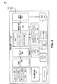
図1は、電力消費量を低減させるための回路102の一構成を例示するブロック図である。回路102は、電力増幅器110と、前置歪み補償器106と、コントローラ122と、電源116と、を含む。回路102内に含まれている要素又はコンポーネントのうちの1つ以上(例えば、前置歪み補償器106、コントローラ122、電力増幅器110及び/又は電源116)は、ハードウェア、ソフトウェア又は両方の組み合わせに実装することができる。例えば、回路102に含まれる要素又はコンポーネントのうちの1つ以上は、回路、回路コンポーネント(例えば、抵抗器、トランジスタ、キャパシタ、誘導子、等)、メモリブロック、レジスタ、処理ブロック及び/又はメモリに格納された、プロセッサで実行される命令(例えば、ソフトウェアコード)に実装することができる。
FIG. 1 is a block diagram illustrating one configuration of a circuit 102 for reducing power consumption. Circuit 102 includes a power amplifier 110, a
電力増幅器110は、送信信号104を増幅することができる。幾つかの構成では、電力増幅器110は、無線送信のために送信信号104の振幅を大きくすることができる。電力増幅器110は、電源116に結合される。電力増幅器110の性能は、電源116によって提供されるバイアス電圧118に基づいて変動する。例えば、電力増幅器110によって提供される増幅の大きさ及び/又は電力増幅器110の直線性は、提供されるバイアス電圧118に基づいて変化することができる。
The power amplifier 110 can amplify the transmission signal 104. In some configurations, the power amplifier 110 can increase the amplitude of the transmitted signal 104 for wireless transmission. Power amplifier 110 is coupled to
電源116は、電源電圧114及びコントローラ122によって提供される電源制御信号120に基づいてバイアス電圧118を生成する。電源116の一例は、切り換えモード電源(SMPS)である。例えば、電源116は、直流−直流(DC−DC)変換器であることができる。電源116は、電源電圧114をより低いバイアス電圧118に低減させることができる。電源電圧114は、例えば、バッテリ、電力アダプタ及び/又はその他の電源によって提供することができる。
The
コントローラ122は、電力増幅器110、電源116及び前置歪み補償器106に結合される。コントローラ122は、送信信号104及びフィードバック信号112に基づいて電源116及び前置歪み補償器106を制御する。特に、コントローラ122は、電力増幅器110が要求事項(例えば、性能上の要求事項)に従って増幅された送信信号108を生成するのを可能にする電圧の組及びプリディストーションから最小バイアス電圧118を決定する。例えば、コントローラ122は、電力増幅器110が以下の図2−3と関連付けて説明される方法200、300のうちの1つ以上により増幅された送信信号108を生成するのを可能にするこの最小バイアス電圧118を決定することができる。
Controller 122 is coupled to power amplifier 110,
コントローラ122は、電源116に電源制御信号120を提供する。電源制御信号120は、特定のバイアス電圧118を生成することを電源116に行わせることができる。例えば、電源制御信号120は、特定のバイアス電圧118に対応するか又は特定のバイアス電圧118を示す1つ以上のパラメータを含むことができる。
Controller 122 provides power control signal 120 to
コントローラ122は、電圧の組からバイアス電圧118を生成することを電源116に行わせることができる。電圧の組は、1つ以上の電圧を含むことができる。例えば、電圧の組は、コントローラ122が電源116に生成させることができる有限の組の個別電圧を備えることができる。幾つかの場合は、電圧の組は、コントローラ122、電源116又は両方の分解能(resolution)によって制限することができる。例えば、電源制御信号120は、有限数のビット、インジケータ又はパラメータによって表すことができる。従って、コントローラ122は、有限数のステップ又は有限数の値に基づいてバイアス電圧118を示すことができる。従って、電力増幅器110が1つ以上の要求事項に従って増幅された送信信号108を生成するのを可能にする電圧の組からの最小バイアス電圧118は、それらの要求事項が依然として満たされている場合の電圧の組内の可能な限り最小の電圧であることができる。従って、電圧の組(存在する場合)内のこの最小バイアス電圧118の次に低い電圧は、電力増幅器110が要求事項に従って増幅された送信信号108を生成するのを可能にしない。
The controller 122 can cause the
コントローラ122は、前置歪み補償器106にプリディストーション制御信号124も提供する。プリディストーション制御信号124は、特定のプリディストーションを送信信号104aに適用することを前置歪み補償器106に行わせることができる。例えば、プリディストーション制御信号124は、特定のプリディストーションを示す1つ以上のパラメータを含むことができる。幾つかの構成では、プリディストーション制御信号124は、プリディストーションを定義するAMAM/AMPMルックアップテーブル(LUT)を示すことができる。さらに加えて又は代替で、プリディストーション制御信号124は、(例えば、多項関数、ボルテラモデル、区分関数、等のうちの1つ以上に基づいて)プリディストーションを関数的に定義する1つ以上のパラメータを含むことができる。
The controller 122 also provides a
前置歪み補償器106は、コントローラ122及び電力増幅器110に結合される。前置歪み補償器106は、送信信号104aにプリディストーションを適用することができる。例えば、前置歪み補償器106は、プリディストーション制御信号124によって指定されたプリディストーションを適用する。送信信号104にプリディストーションを適用することは、電力増幅器110が1つ以上の要求事項を満たす増幅された送信信号108を依然として生成する一方でより低いバイアス電圧118で動作するのを可能にすることができる。1つ以上の要求事項の例は、隣接チャネル漏洩比(ACLR)、隣接チャネル電力比(ACPR)、ピーク対平均比(PAR)、エラーベクトルマグニチュード(EMV)、出力電力(例えば、Pout)、受信帯域雑音(RxBN)、送信(Tx)チェーン全体の利得及び/又は送信(Tx)チェーン全体の電力に関する1つ以上の指定値を含む。例えば、利得又は電力は、送信の観点からは等値であることができる。例えば、利得が既知である場合は、ベースバンド送信機が生成する送信信号(例えば、送信信号104)は、デバイス(例えば、回路102)の出力電力の予測を可能にすることができる。
図2は、回路102によって電力消費量を低減させるための方法200の一構成を例示した流れ図である。回路102は、送信信号104及びフィードバック信号112を同時並行して捕捉する202ことができる。一例では、コントローラ122は、重なり合う期間に送信信号104及びフィードバック信号112を捕捉する。
FIG. 2 is a flow diagram illustrating one configuration of a
回路102は、電力増幅器110が要求事項に従って増幅された送信信号108を生成することを可能にする電圧の組から最小バイアス電圧118を決定する204ことができる。例えば、コントローラ122は、現在の電圧に対応する電力増幅器の特性を決定する。コントローラ122は、電圧の組内の次の(例えば、より低い)電圧に関するプリディストーションも決定し、この次の電圧に対応する性能を推定する。コントローラ122は、電力増幅器110が要求事項に従って増幅された送信信号108を生成するのを可能にする電圧の組から最小バイアス電圧118を決定することを試みてプリディストーション決定すること及び性能を推定することをさらに繰り返すことができる。 The circuit 102 can determine 204 a minimum bias voltage 118 from a set of voltages that enables the power amplifier 110 to generate an amplified transmit signal 108 according to requirements. For example, the controller 122 determines the characteristic of the power amplifier that corresponds to the current voltage. The controller 122 also determines predistortion for the next (eg, lower) voltage in the set of voltages and estimates the performance corresponding to this next voltage. The controller 122 attempts to determine the minimum bias voltage 118 from the set of voltages that allows the power amplifier 110 to generate an amplified transmit signal 108 according to requirements, and predistortion determination and performance estimation. This can be repeated further.
回路102は、少なくとも1つのパラメータを設定する206ことができる。例えば、コントローラ122は、前置歪み補償器106によって送信信号104に適用されるプリディストーションを示す又は定義する1つ以上のパラメータをプリディストーション制御信号124で送信する。例えば、プリディストーション制御信号124は、プリディストーションを定義するAMAM/AMPMルックアップテーブル(LUT)を示すことができる。コントローラ122は、決定された204最小バイアス電圧118を示すパラメータを電源制御信号120で送信することもできる。幾つかの構成では、回路102(例えば、コントローラ122)は、1つ以上の追加のパラメータ、例えば、1つ以上のベースバンド利得及び/又は1つ以上の無線トランシーバ(RTR)利得、を設定することができる。
The circuit 102 can set 206 at least one parameter. For example, the controller 122 transmits one or more parameters in the
回路102は、組206パラメータにより送信信号104をプリディストーションして増幅することができる。回路102は、結果的に得られた増幅された送信信号108を送信することもできる。
The circuit 102 can predistort and amplify the transmission signal 104 according to the
図3は、電力消費量を回路102によって低減させるための方法300のより具体的な構成を例示した流れ図である。回路102は、現在のバイアス電圧118(例えば、Vcc(i))を初期電圧(例えば、Vcc(0))に設定する302ことができる。一例では、回路102は、この初期の電圧で現在のバイアス電圧118を生成することを電源116に行わせる。
FIG. 3 is a flow diagram illustrating a more specific configuration of a
幾つかの構成では、回路102は、初期電圧を決定するために基本的平均電力トラッキング(APT)を行うことができる。上述されるように、この初期電圧は、回路102(例えば、電力増幅器110)が温度、周波数及び/又は部品の変動に関する1つ以上の要求事項に従って増幅された送信信号108を生成するのを可能にすることができる。しかしながら、幾つかの場合は、この初期電圧は、電力増幅器110が1つ以上の要求事項に従って増幅された送信信号108を生成するのを可能にする電圧の組内の最小電圧よりも高いことができる。従って、初期電圧は、効率が低下することがあり、電力を浪費させることがある。 In some configurations, the circuit 102 can perform basic average power tracking (APT) to determine the initial voltage. As described above, this initial voltage allows circuit 102 (eg, power amplifier 110) to generate an amplified transmission signal 108 that is amplified in accordance with one or more requirements regarding temperature, frequency, and / or component variations. Can be. However, in some cases, this initial voltage may be higher than the minimum voltage in the set of voltages that allows the power amplifier 110 to generate an amplified transmission signal 108 in accordance with one or more requirements. it can. Thus, the initial voltage can reduce efficiency and waste power.
回路102は、送信信号104及びフィードバック信号112を同時並行して捕捉する304ことができる。例えば、コントローラ122は、送信信号104及びフィードバック信号112を重なり合う期間に捕捉する304ことができる。より具体的には、回路(例えば、コントローラ122)は、送信信号104及びフィードバック信号112の捕捉304をほぼ同時にトリガすることができる。幾つかの構成では、回路102(例えば、コントローラ122)は、前置歪み補償器106(の出力)後に送信信号104bを捕捉する304。その他の構成では、回路102(例えば、コントローラ122)は、前置歪み補償器106(の出力)前に送信信号104aを捕捉する304。
The circuit 102 can capture 304 the transmit signal 104 and the feedback signal 112 simultaneously. For example, the controller 122 can capture 304 the transmit signal 104 and the feedback signal 112 in overlapping periods. More specifically, a circuit (eg, controller 122) can trigger
フィードバック信号112は、電力増幅器110の後に捕捉される304。幾つかの構成では、回路102(例えば、コントローラ122)は、デュプレクサ及びスイッチ(図1に示されていない)の前でフィードバック信号112を捕捉する304ことができる。その他の構成では、回路102(例えば、コントローラ122)は、デュプレクサ及びスイッチ(図1に示されていない)の後でフィードバック信号112を捕捉する304ことができる。 Feedback signal 112 is captured 304 after power amplifier 110. In some configurations, the circuit 102 (eg, controller 122) can capture 304 the feedback signal 112 in front of a duplexer and switch (not shown in FIG. 1). In other configurations, circuit 102 (eg, controller 122) may capture 304 feedback signal 112 after a duplexer and switch (not shown in FIG. 1).
回路102は、現在のバイアス電圧(例えば、Vcc(i))に対応する電力増幅器の特性を決定する306ことができる(ここで、iは、現在のバイアス電圧を表すインデックスである)。例えば、回路102(コントローラ122)は、現在のバイアス電圧に対応する捕捉された304送信信号104及びフィードバック信号112に基づいて電力増幅器の特性を決定する306。電力増幅器の特性は、現在のバイアス電圧での電力増幅器の応答(例えば、出力電圧(例えば、Vout)対入力電圧(例えば、Vin))を示すことができる。応答は、電力増幅器の直線性(例えば、電力増幅器の特性がほぼ直線である電圧の範囲)を示すことができる。 Circuit 102 may determine 306 a power amplifier characteristic corresponding to a current bias voltage (eg, Vcc (i)), where i is an index representing the current bias voltage. For example, the circuit 102 (controller 122) determines 306 the characteristics of the power amplifier based on the captured 304 transmit signal 104 and feedback signal 112 corresponding to the current bias voltage. The characteristics of the power amplifier can indicate the response of the power amplifier at the current bias voltage (eg, output voltage (eg, Vout) vs. input voltage (eg, Vin)). The response can indicate the linearity of the power amplifier (eg, a voltage range where the power amplifier characteristics are approximately linear).
幾つかの構成では、回路102(例えば、コントローラ122)は、電力増幅器の特性を次のように決定する306。コントローラ122が捕捉された304送信信号104及びフィードバック信号112からマッチしている信号を抽出する。例えば、コントローラ122は、マッチしている信号を抽出するために周波数誤り訂正、位相訂正粗マッチング、微細
マッチング及び等化のうちの1つ以上を行う。コントローラ122は、電力増幅器の特性(例えば、電力増幅器110のAMAM/AMPM特性)を決定する306ために位相訂正も行い、及び、任意選択で、ビニングと平均化、曲線当てはめ及び/又はその他の同等のデータ縮小法を行う。
In some configurations, circuit 102 (eg, controller 122) determines 306 the characteristics of the power amplifier as follows. The controller 122 extracts a matching signal from the captured 304 transmission signal 104 and the feedback signal 112. For example, the controller 122 performs one or more of frequency error correction, phase correction coarse matching, fine matching, and equalization to extract matching signals. The controller 122 also performs phase correction to determine 306 power amplifier characteristics (eg, AMAM / AMPM characteristics of the power amplifier 110), and optionally binning and averaging, curve fitting and / or other equivalents. The data reduction method is performed.
回路102(例えば、コントローラ122)は、電圧の組内の次のバイアス電圧(例えば、Vcc(i+1))に対応する次のプリディストーションを決定する308ことができる。次のバイアス電圧(例えば、Vcc(i+1))は、電圧の組内の(現在のバイアス電圧よりも)低い電圧であることができる。この次のプリディストーションは、データフィードバック及び/又は予め格納された校正に基づいて決定される308。幾つかの構成では、例えば、(電力増幅器110の)Vosat及びバイアス(例えば、電源)電圧Vccの関係を決定する校正を事前に行うことができる。校正結果は、デバイスに予め格納することができる。データフィードバックは、ワンショット(one shot)又は適応型であることができる。 The circuit 102 (eg, controller 122) can determine 308 the next predistortion that corresponds to the next bias voltage (eg, Vcc (i + 1)) in the set of voltages. The next bias voltage (eg, Vcc (i + 1)) can be a lower voltage in the set of voltages (than the current bias voltage). This next predistortion is determined 308 based on data feedback and / or pre-stored calibration. In some configurations, for example, calibration can be performed in advance to determine the relationship between Vosat (of power amplifier 110) and bias (eg, power supply) voltage Vcc. The calibration result can be stored in advance in the device. Data feedback can be one shot or adaptive.
ワンショットでプリディストーションを決定する308(例えば、予測する)一例が次に説明される。コントローラ122は、次のバイアス電圧(例えば、Vcc(i+1)に対応する次の電力増幅器の特性を決定する(例えば、予測する)ために飽和電圧(例えば、Vosat)及び様々なバイアス電圧(例えば、Vcc)での利得に基づいて決定された306電力増幅器の特性(例えば、現在の電圧Vcc(i)に対応するAMAM曲線)をスケーリングする。次に、コントローラ122は、プリディストーションを決定する308ために次の電圧に対応する次の電力増幅器の特性を反転させる。 An example of 308 (eg, predicting) determining predistortion in one shot is described next. The controller 122 may determine a saturation voltage (e.g., Vosat) and various bias voltages (e.g., Vsat) (e.g. 306 power amplifier characteristics (eg, AMAM curve corresponding to the current voltage Vcc (i)) determined based on the gain at Vcc) Next, the controller 122 determines 308 to determine predistortion. The characteristics of the next power amplifier corresponding to the next voltage are inverted.
回路102(例えば、コントローラ122)は、次のバイアス電圧(例えば、Vcc(i+1))に対応する性能を推定する310ことができる。例えば、コントローラ122は、次のバイアス電圧(例えば、Vcc(i+1))に対応する1つ以上の性能メトリックを推定する。性能(例えば、1つ以上の性能メトリック)を推定する310ことは、次の電圧に対応する決定された308次のプリディストーションに基づくこともできる。1つ以上の性能メトリックの例は、隣接チャネル漏洩比(ACLR)と、隣接チャネル電力比(ACPR)と、ピーク対平均比(PAR)と、エラーベクトルマグニチュード(EMV)と、出力電力(例えば、Pout)と、受信帯域雑音(RxMB)と、利得と、を含む。 The circuit 102 (eg, controller 122) can estimate 310 the performance corresponding to the next bias voltage (eg, Vcc (i + 1)). For example, the controller 122 estimates one or more performance metrics corresponding to the next bias voltage (eg, Vcc (i + 1)). Estimating 310 performance (eg, one or more performance metrics) may also be based on the determined 308th order predistortion corresponding to the next voltage. Examples of one or more performance metrics include adjacent channel leakage ratio (ACLR), adjacent channel power ratio (ACPR), peak-to-average ratio (PAR), error vector magnitude (EMV), and output power (eg, Pout), reception band noise (RxMB), and gain.
回路102(例えば、コントローラ122)は、電力増幅器が1つ以上の要求事項に従って増幅された送信信号を生成するのを可能にする電圧の組及びプリディストーションから最小バイアス電圧を決定することを試みて、電圧の組内の次のバイアス電圧に対応する次のプリディストーションを決定する308こと及び次のバイアス電圧に対応する性能を推定する310ことを繰り返すことができる。幾つかの構成では、繰り返しは次のように実施することができる。 Circuit 102 (eg, controller 122) attempts to determine a minimum bias voltage from a set of voltages and predistortion that allows a power amplifier to generate an amplified transmit signal in accordance with one or more requirements. 308 determining the next predistortion corresponding to the next bias voltage in the set of voltages and estimating 310 the performance corresponding to the next bias voltage can be repeated. In some configurations, the iteration can be performed as follows.
回路102(例えば、コントローラ122)は、次のバイアス電圧(例えば、Vcc(i+1))及び対応するプリディストーションが、電力増幅器110が要求事項に従って増幅された送信信号1208を生成するのを可能にするかどうかを決定する312ことができる。例えば、コントローラ122は、次の電圧(例えば、Vcc(i+1))及び対応するプリディストーションが、電力増幅器110が1つ以上の性能上の要求事項を満たす増幅された送信信号108を生成するのを可能にするかどうかを決定する。幾つかの構成では、この決定312は、次のバイアス電圧(例えば、Vcc(i+1))に対応する推定された310性能を1つ以上の性能ターゲットと比較することによって行うことができる。例えば、回路102(例えば、コントローラ122)は、1つ以上の性能メトリックを、隣接チャネル漏洩比(ACLR)、隣接チャネル電力比(ACPR)、ピーク対平均比(PAR)、エラーベクトルマグニチュード(EVM)、出力電力(例えば、Pout)、受信帯域雑音(RxBN)及び/又は利得に関する1つ以上の性能ターゲットと比較することができる。これらの構成では、推定された310性能メトリックが性能ターゲットを満たす場合は、次のバイアス電圧及び対応するプリディストーションが、電力増幅器110が要求事項に従って増幅された送信信号を生成するのを可能にする。そうでない場合は、次のバイアス電圧及び対応するプリディストーションは、電力増幅器110が要求事項に従って増幅された送信信号を生成するのを可能にしない。
Circuit 102 (eg, controller 122) allows the next bias voltage (eg, Vcc (i + 1)) and corresponding predistortion to allow power amplifier 110 to generate an amplified transmit signal 1208 according to requirements. Whether 312 can be determined. For example, the controller 122 causes the next voltage (eg, Vcc (i + 1)) and the corresponding predistortion to cause the power amplifier 110 to generate an amplified transmit signal 108 that meets one or more performance requirements. Decide whether to allow it. In some configurations, this
電圧の組内の次のバイアス電圧(例えば、Vcc(i+1))及び対応するプリディストーションが、電力増幅器110が要求事項に従って増幅された送信信号108を生成することを可能にする場合は、回路102(例えば、コントローラ122)は、次の繰り返しに進むか又は戻り、プリディストーションを決定し308及び電圧の組内の1つ以上の後続する(例えば、より低い)電圧に対応する性能を推定する310ことができる。例えば、回路102(例えば、コントローラ122)は、現在のバイアス電圧を低下させ318、電圧の組内の次のバイアス電圧に対応するプリディストーションを決定する308ことに戻ることができる。例えば、インデックスiを増加させることができる(例えば、i=i+1)。換言すると、インデックスiは、増加させることができ、例えば、バイアス電圧Vcc(i+1)<Vcc(i)であることができる。現在のバイアス電圧を低下させても318実際にはバイアス電圧118を設定又は更新できないことが注目されるべきである。例えば、コントローラ122は、設定される314まではバイアス電圧118を設定するためのパラメータを電源制御信号120で送信することはできない。
If the next bias voltage in the set of voltages (eg, Vcc (i + 1)) and the corresponding predistortion allow the power amplifier 110 to generate an amplified transmit signal 108 according to requirements, the circuit 102 (E.g., controller 122) proceeds or returns to the next iteration to determine predistortion 308 and
明確化を目的として、現在のバイアス電圧を低下させる318ことは、次の例に従って行うことができる。“新しい”現在の電圧(例えば、Vcc(i))を前回の繰り返しからの“古い”次の電圧(例えば、前のVcc(i+1))まで低下させる(例えば、設定する)ことができる。この場合は、“新しい”次の電圧(例えば、新しいVcc(i+1))が、電圧の組内の後続する(例えば、より低い)電圧である(例えば、組内に後続する電圧が存在する場合)。従って、回路102は、電力増幅器110が要求事項に従って増幅された送信信号108を生成するのを可能にする電圧の組内の最小バイアス電圧118及び対応するプリディストーションが決定されるまで(可能な場合)次の電圧(例えば、Vcc(i+1))を決定し308及び対応するプリディストーションを推定する310ことができる。(現在のバイアス電圧を低下させた318後に)次のバイアス電圧(例えば、Vcc(i+1))が電圧の組内に存在しない場合は、回路102の動作は、少なくとも1つのパラメータを設定する314ことに進むことができる。
For the sake of clarity, reducing 318 the current bias voltage can be done according to the following example. The “new” current voltage (eg, Vcc (i)) can be reduced (eg, set) to the “old” next voltage (eg, previous Vcc (i + 1)) from the previous iteration. In this case, the “new” next voltage (eg, new Vcc (i + 1)) is a subsequent (eg, lower) voltage in the set of voltages (eg, if there is a subsequent voltage in the set). ). Thus, the circuit 102 (if possible) determines the minimum bias voltage 118 and corresponding predistortion in the set of voltages that allow the power amplifier 110 to generate an amplified transmission signal 108 according to requirements. ) The next voltage (eg, Vcc (i + 1)) can be determined 308 and a
電圧の組内の次のバイアス電圧(例えば、Vcc(i+1))及び対応する次のプリディストーションが、電力増幅器110が要求事項に従って増幅された送信信号108を生成するのを可能にしない場合は、回路102(例えば、コントローラ122)は、少なくとも1つのパラメータを設定する314ことができる。例えば、コントローラ122は、現在のバイアス電圧118(例えば、VCC(i))を示すパラメータを電源制御信号120で送信することができる。例えば、現在のバイアス電圧(例えば、VCC(i))は、電力増幅器110が要求事項に従って増幅された送信信号108を生成するのを可能にする最小バイアス電圧であることができ、その理由は、それが、次のバイアス電圧(例えば、Vcc(i+1))が要求事項を満たすことができないと決定される前の最後の該バイアス電圧であったためである。 If the next bias voltage in the set of voltages (eg, Vcc (i + 1)) and the corresponding next predistortion does not allow the power amplifier 110 to generate an amplified transmit signal 108 according to requirements, Circuit 102 (eg, controller 122) may set 314 at least one parameter. For example, the controller 122 can send a parameter indicating the current bias voltage 118 (eg, VCC (i)) in the power supply control signal 120. For example, the current bias voltage (eg, VCC (i)) can be the minimum bias voltage that allows the power amplifier 110 to generate an amplified transmit signal 108 in accordance with requirements, because This is because the next bias voltage (eg, Vcc (i + 1)) was the last bias voltage before it was determined that the requirement could not be met.
さらに加えて又は代替として、コントローラ122は、送信信号104に対して前置歪み補償器106によって適用される(現在のバイアス電圧(例えば、Vcc(i)に対応する)プリディストーションを示す又は定義する1つ以上のパラメータをプリディストーション制御信号124で送信する。例えば、プリディストーション制御信号124は、プリディストーションを定義するAMAM/AMPMルックアップテーブル(LUT)を示すことができる。幾つかの構成では、回路102(例えば、コントローラ122)は、1つ以上の追加のパラメータ、例えば、1つ以上のベースバンド利得及び/又は1つ以上の無線トランシーバ(RTR)利得、を設定することができる。
Additionally or alternatively, the controller 122 indicates or defines the predistortion (eg, corresponding to Vcc (i)) applied by the
回路102は、組314パラメータにより送信信号104をプリディストーション及び増幅することができる。回路102は、その結果えられた増幅された送信信号108を送信することもできる。 The circuit 102 can predistort and amplify the transmitted signal 104 according to the set 314 parameters. The circuit 102 can also transmit the resulting amplified transmission signal 108.
回路102は、1つ以上の基準に基づいて再評価が必要かどうかを決定する316ことができる。1つ以上の基準は、例えば、定期的なトリガ、(例えば、最後の捕捉304又は最後の設定314以降に)ある時間量が経過しているかどうか、及び(例えば、最後の捕捉304又は最後の設定314以降に)温度が変化(例えば、増大)しているかどうか、を含むことができる。再評価が必要であると回路102が決定した316場合は、回路102は、送信信号104及びフィードバック信号112を捕捉する304ことに戻ることができる。
Circuit 102 may determine 316 whether a re-evaluation is necessary based on one or more criteria. One or more criteria can be, for example, a periodic trigger, whether a certain amount of time has passed (eg, since the
回路102は、さらに加えて又は代替で、欠陥性能が生じるかどうかを決定する316ことができる。欠陥性能は、1つ以上の要求事項が満たされていないときに生じることがある。例えば、回路102は、1つ以上の要求事項が満たされているかどうかを決定する316。1つ以上の要求事項の例は、隣接チャネル漏洩比(ACLR)、隣接チャネル電力比(ACPR)、ピーク対平均比(PAR)、エラーベクトルマグニチュード(EMV)、出力電力(例えば、Pout)、受信帯域雑音(RxMB)及び/又は利得に関する要求事項を含む。 The circuit 102 may additionally or alternatively determine 316 whether defect performance occurs. Defect performance may occur when one or more requirements are not met. For example, the circuit 102 determines 316 whether one or more requirements are met 316. Examples of one or more requirements are adjacent channel leakage ratio (ACLR), adjacent channel power ratio (ACPR), peak It includes requirements regarding to average ratio (PAR), error vector magnitude (EMV), output power (eg, Pout), receive band noise (RxMB) and / or gain.
欠陥性能が生じた場合は、回路102は、現在のバイアス電圧を初期電圧(例えば、Vcc(0)又は“安全である”とみなされるその他のいずれかのバイアス電圧)に設定する302ことに戻る(例えば、フォールバック)することができる。例えば、インデックスiは、0にリセットすることができる。例えば、回路102は、平均電力トラッキング(APT)に基づいて現在のバイアス電圧を初期電圧に設定する302ことができる。さらに加えて又は代替で、初期バイアス電圧は、アルゴリズムが電圧を(例えば、Vcc(i)からVcc(i+1)に)低下させる一方で決定しているその他のバイアス電圧であることができる。それらのステップのいずれでも、1つ以上の計算は、予測される性能上の要求事項(例えば、ACLR、RxBN、利得、等)において十分なマージンを有するという意味でバイアス電圧が“安全である”とみなすことができる。従って、そのステップ中に利用されるバイアス電圧(例えば、Vcc)は、次の“安全な”フォールバックポイントになることができる。しかしながら、再評価が必要でない場合及び/又は欠陥性能が生じない場合は、回路102は、電力増幅器110が要求事項に従って増幅された送信信号108を生成するのを可能にする電圧の組からの最小電圧である現在のバイアス電圧118(例えば、Vcc(i))に基づいて現在の設定により動作を続けることができる。 If defective performance occurs, the circuit 102 returns to 302 setting the current bias voltage to an initial voltage (eg, Vcc (0) or any other bias voltage that is considered “safe”). (Eg, fallback). For example, index i can be reset to zero. For example, the circuit 102 can set 302 the current bias voltage to an initial voltage based on average power tracking (APT). Additionally or alternatively, the initial bias voltage can be any other bias voltage that the algorithm determines while decreasing the voltage (eg, from Vcc (i) to Vcc (i + 1)). In any of these steps, the bias voltage is “safe” in the sense that one or more calculations have sufficient margin in the expected performance requirements (eg, ACLR, RxBN, gain, etc.). Can be considered. Thus, the bias voltage (eg, Vcc) utilized during that step can be the next “safe” fallback point. However, if re-evaluation is not required and / or if no defect performance occurs, the circuit 102 is the minimum from the set of voltages that allows the power amplifier 110 to generate an amplified transmit signal 108 according to requirements. The operation can be continued with the current setting based on the current bias voltage 118 (eg, Vcc (i)).
図4は、電力増幅器の特性426の一例を示したグラフである。特に、図4は、3.35ボルト(V)の現在のバイアス電圧418に対応する電力増幅器の特性426の一例を示す。電力増幅器の特性426は、増幅器入力電圧430対増幅器出力電圧428の絶対値に関して例示される。図4において、横軸(例えば、x)は、送信信号(例えば、アップコンバージョンされて電力増幅器110への入力になる送信信号104b)の振幅の最下位ビット(LSB)で表記される。さらに、縦軸(例えば、y)は、フィードバック信号(例えば、フィードバック信号112)をデジタル化するために使用されるダウンコンバージョンフィードバック経路及びアナログ−デジタル変換器(ADC)の実装に依存して、任意の利得スケーリングを有することができるフィードバック受信機(例えば、コントローラ122)の最下位ビット(LSB)が単位である。
FIG. 4 is a graph showing an example of the characteristic 426 of the power amplifier. In particular, FIG. 4 shows an example of a power amplifier characteristic 426 corresponding to a current bias voltage 418 of 3.35 volts (V). Power amplifier characteristic 426 is illustrated with respect to the absolute value of
例えば、回路102(例えば、コントローラ122)は、3.35Vの現在のバイアス電圧418に対応する捕捉された送信信号104及びフィードバックされた信号112に基づいて電力増幅器の特性426を決定する。電力増幅器の特性426は、現在のバイアス電圧418での電力増幅器110の応答(例えば、出力電圧(例えば、Vout)対入力電圧(例えば、Vin))を示すことができる。応答は、電力増幅器110の直線性(例えば、電力増幅器の特性426がほぼ直線である電圧の範囲)を示すことができる。 For example, the circuit 102 (eg, controller 122) determines the power amplifier characteristics 426 based on the captured transmitted signal 104 and the fed back signal 112 corresponding to a current bias voltage 418 of 3.35V. The power amplifier characteristic 426 may indicate the response of the power amplifier 110 at the current bias voltage 418 (eg, output voltage (eg, Vout) versus input voltage (eg, Vin)). The response can indicate the linearity of the power amplifier 110 (eg, a voltage range where the power amplifier characteristic 426 is approximately linear).
幾つかの構成では、回路102(例えば、コントローラ122)は、電力増幅器の特性を次のように決定する。コントローラ122は、捕捉された送信信号104及びフィードバック信号112からマッチしている信号を抽出する。例えば、コントローラ122は、マッチしている信号を抽出するために周波数誤り訂正、粗マッチング、微細マッチング及び等化のうちの1つ以上を実施する。コントローラ122は、位相訂正及び任意選択でビニングも行う。コントローラ122は、電力増幅器の特性426(例えば、電力増幅器110のAMAM/AMPM特性)を決定するために曲線当てはめをさらに行う。 In some configurations, the circuit 102 (eg, controller 122) determines the characteristics of the power amplifier as follows. The controller 122 extracts a matching signal from the captured transmission signal 104 and the feedback signal 112. For example, the controller 122 performs one or more of frequency error correction, coarse matching, fine matching, and equalization to extract matching signals. The controller 122 also performs phase correction and optionally binning. Controller 122 further performs curve fitting to determine power amplifier characteristics 426 (eg, AMAM / AMPM characteristics of power amplifier 110).
図5は、推定される電力増幅器の特性532の一例を示したグラフである。特に、図5は、3.35Vの現在のバイアス電圧に対応する(測定された)電力増幅器の特性526の一例及び3.05Vの次のバイアス電圧に対応する(推定された)電力増幅器の特性532の一例を示す。(推定された)電力増幅器の特性532は、増幅器入力電圧540対増幅器出力電圧528の絶対値に関して例示される。図5では、軸は、上記の図4に関して同様に詳述されるような単位を有することができる。
FIG. 5 is a graph showing an example of the estimated power amplifier characteristic 532. In particular, FIG. 5 illustrates an example of a power amplifier characteristic 526 (measured) corresponding to a current bias voltage of 3.35V and a power amplifier characteristic (estimated) corresponding to a next bias voltage of 3.05V. An example of 532 is shown. The (estimated) power amplifier characteristic 532 is illustrated with respect to the absolute value of the amplifier input voltage 540 versus the
回路102(例えば、コントローラ122)は、電圧の組内の次のバイアス電圧(例えば、Vcc(i+1)=3.05V)に対応するプリディストーションを決定することができる。次のバイアス電圧(例えば、Vcc(i+1))は、電圧の組内の現在の電圧(例えば、Vcc(i)=3.35V)と比較してより低い電圧を有することができる。プリディストーションは、データフィードバック及び/又は予め格納された校正に基づいて決定される。 Circuit 102 (eg, controller 122) can determine a predistortion corresponding to the next bias voltage in the set of voltages (eg, Vcc (i + 1) = 3.05V). The next bias voltage (eg, Vcc (i + 1)) may have a lower voltage compared to the current voltage in the voltage set (eg, Vcc (i) = 3.35V). Predistortion is determined based on data feedback and / or prestored calibration.
特に、図5は、プリディストーションをワンショットで決定する(例えば、予測する)例の一部分を示す。コントローラ122は、決定された(例えば、測定された)電力増幅器の特性526(例えば、次のバイアス電圧(例えば、Vcc(i+1)=3.05Vに対応する次の電力増幅器の特性532を決定(例えば、予測)するために飽和電圧(例えば、Vosat)及び様々なバイアス電圧(例えば、Vcc)での利得に基づいて現在の電圧(Vcc(i)=3.35Vに対応するAMAM曲線)をスケーリングする。 In particular, FIG. 5 shows a portion of an example in which predistortion is determined (eg, predicted) in one shot. The controller 122 determines a determined (eg, measured) power amplifier characteristic 526 (eg, a next power amplifier characteristic 532 corresponding to the next bias voltage (eg, Vcc (i + 1) = 3.05V)). For example, to scale the current voltage (AMAM curve corresponding to Vcc (i) = 3.35V) based on gain at saturation voltage (eg, Vosat) and various bias voltages (eg, Vcc) to predict To do.
図6は、デジタルプリディストーションルックアップテーブル638の例を示したグラフである。特に、プリディストーションの例640、642は、デジタルプリディストーション入力634対デジタルプリディストーション出力636に関して示される。横軸及び縦軸は、プリディストーション中のデジタル送信信号(例えば、送信信号104)の振幅の最下位ビット(LSB)で表すことができる。例示されるプリディストーション640、642は、デジタルプリディストーションAMAMルックアップテーブル(LUT)638に実装することができる。プリディストーションは、AMAM LUTに加えてAMPM LUT内に実装することができ及び/又はAMAM LUTは、幾つかの構成ではAMPM LUTと同じテーブル内に組み入れることができることが注目されるべきである。
FIG. 6 is a graph showing an example of the digital predistortion lookup table 638. In particular, predistortion examples 640, 642 are shown with respect to a digital predistortion input 634 versus a digital predistortion output 636. The horizontal axis and the vertical axis can be represented by the least significant bit (LSB) of the amplitude of the digital transmission signal (eg, transmission signal 104) during predistortion. The illustrated
図6では、現在のバイアス電圧(例えば、Vcc(i)=3.35V)に対応する第1のプリディストーション640が例示される。次のバイアス電圧(例えば、Vcc(i)=3.05V)に対応する第2のプリディストーション642も例示される。第2のプリディストーション642は、図5に例示される次のバイアス電圧(Vcc(i+1)=3.05V)に対応する(推定される)次の電力増幅器の特性532に基づいて回路102(例えば、コントローラ122)によって決定することができる。換言すると、図6は、図5において説明される例の後続する一部分を例示し、コントローラ122は、第2のプリディストーション642を決定するために次の電圧(例えば、Vcc(i+1)=3.05V)に対応する電力増幅器の特性532を反転させる。この例では、コントローラ122は、第2のプリディストーション642が、電力増幅器110が要求事項に従って増幅された送信信号108を生成するのを可能にする電圧の組内の最小バイアス電圧に対応する場合に、デジタルプリディストーションAMAM LUT638を設定するために前置歪み補償器106にプリディストーション制御信号124でパラメータを送信することができる。
FIG. 6 illustrates a
図7は、電力消費量を低減させるための電子デバイス702の一構成を例示したブロック図である。電子デバイス702は、図1と関係させて説明される回路102の一例であることができる。電子デバイス702は、電力増幅器710と、前置歪み補償器706と、コントローラ722と、電源716と、変調器746と、コンディショナ748と、デジタル−アナログ変換器750(DAC)と、アップコンバータ752と、ダウンコンバータ754と、アナログ−デジタル変換器756(ADC)と、を含む。電子デバイス702に含まれる要素又はコンポーネントのうちの1つ以上は、ハードウェア、ソフトウェアまたは両方の組み合わせ内に実装することができる。例えば、電子デバイス702に含まれる要素又はコンポーネントのうちの1つ以上は、回路、回路コンポーネント(例えば、抵抗器、トランジスタ、キャパシタ、誘導子、等)、メモリブロック、レジスタ、処理ブロック及び/又はメモリに格納された、プロセッサで実行される命令(例えば、ソフトウェアコード)に実装することができる。
FIG. 7 is a block diagram illustrating one configuration of the electronic device 702 for reducing power consumption. The electronic device 702 can be an example of the circuit 102 described in connection with FIG. The electronic device 702 includes a
電力増幅器710は、送信信号704を増幅することができる。幾つかの構成では、電力増幅器710は、無線送信のために送信信号704の振幅を大きくすることができる。電力増幅器710は、電源716に結合される。電力増幅器710の性能は、電源716によって提供されるバイアス電圧718に基づいて変動する。例えば、電力増幅器710によって提供される増幅の大きさ及び/又は電力増幅器710の直線性は、提供されるバイアス電圧718に基づいて変化することができる。
The
電源716は、電源電圧714及びコントローラ722によって提供される電源制御信号720に基づいてバイアス電圧718を生成する。電源716の一例は、切り換えモード電源(SMPS)である。例えば、電源716は、直流−直流(DC−DC)変換器であることができる。電源716は、電源電圧714をより低いバイアス電圧718に低減させることができる。電源電圧714は、例えば、バッテリ、電力アダプタ及び/又はその他の電源によって提供することができる。
The
変調器746は、前置歪み補償器706に結合され、それは、コントローラ722及びコンディショナ748に結合される。送信情報744が変調器746に提供される。変調器746は、変調方式(位相偏移変調(PSK)、直交振幅変調(QAM)、等)により送信情報744を変調し、前置歪み補償器706に提供される変調された送信信号704aを生成する。前置歪み補償器706は、変調された送信信号704aにプリディストーションを適用することができる。しかしながら、前置歪み補償器706は、変調された送信信号704aにプリディストーションを適用することが常にできるわけではない(例えば、増幅された送信信号708を直線化するためにプリディストーションが要求されないとき)。結果的に得られる(プリディストーションされた)送信信号704bは、コンディショナ748に提供される。コンディショナ748は、コンディショニングされた送信信号704cを生成するために(プリディストーションされた)送信信号704bに関して1つ以上の動作を行うことができる。例えば、コンディショナ748は、(プリディストーションされた)送信信号704bに関して、アップサンプリング、フィルタリング、等を行うことができる。
コンディショナ748は、コントローラ722及びデジタル−アナログ変換器750に結合される。コンディショニングされた送信信号704cは、コントローラ722及びデジタル−アナログ変換器750に提供される。デジタル−アナログ変換器750は、コンディショニングされた送信信号704cをアナログ送信信号704dに変換する。デジタル−アナログ変換器750は、アップコンバータ752に結合される。アナログ送信信号704dは、アップコンバータ752に提供され、それは、アナログ送信信号704dを(例えば、無線周波数(RF)範囲内に)アップコンバージョンしてアップコンバージョンされた送信信号704eを生成し、それは、電力増幅器710に提供される。
電力増幅器710は、スイッチ/デュプレクサ(図7に示されていない)に結合され、それらは、アンテナ(図7に示されていない)に結合することができる。電力増幅器710は、ダウンコンバータ754に結合される。電力増幅器710は、増幅された送信信号708を生成することができる。増幅された送信信号708からダウンコンバータ754にフィードバック信号712aを提供することができる。フィードバック信号712aは、スイッチ又はデュプレクサの前又は後でコントローラ722によって捕捉することができることが注目されるべきである。
The
ダウンコンバータ754は、フィードバック信号712aを(例えば、ベースバンド周波数範囲内に)ダウンコンバージョンしてダウンコンバージョンされたフィードバック信号712bを生成する。幾つかの構成では、ダウンコンバータ754は、アップコンバータ752よりも小さいダイナミックレンジを変換することが可能である。例えば、ダウンコンバータ754は、70乃至80dBの電力の電力範囲内にあることができるアナログ送信信号704dを変換することができるアップコンバータ752と比較して、20乃至30dBの電力の電力範囲内にあることができるフィードバック信号712aを変換することができる。幾つかの構成では、アップコンバータ752及びダウンコンバータ754は、同じ回路(例えば、無線トランシーバ(RTR))に実装することができ、その他の構成では、アップコンバータ752及びダウンコンバータ754は、別々の回路(例えば、無線トランシーバ(RTR))に実装することができる。ダウンコンバータ754は、アナログ−デジタル変換器756に結合される。ダウンコンバージョンされたフィードバック信号712bは、アナログ−デジタル変換器756に提供される。
アナログ−デジタル変換器756は、ダウンコンバージョンされたフィードバック信号712bをデジタルフィードバック信号712cに変換する。アナログ−デジタル変換器756は、コントローラ722に結合される。デジタルフィードバック信号712cは、コントローラ722に提供される。 The analog-to-digital converter 756 converts the down-converted feedback signal 712b into a digital feedback signal 712c. Analog to digital converter 756 is coupled to controller 722. Digital feedback signal 712 c is provided to controller 722.
幾つかの構成では、フィードバック信号712(例えば、フィードバック信号712a、ダウンコンバージョンされたフィードバック信号712b及びデジタルフィードバック信号712c)は、4つの信号を備えることができる。例えば、フィードバック信号712は、微分(differential)同相成分(例えば、I+及びI−)及び微分直交成分(例えば、Q+及びQ−)を備えることができる。これらの構成では、これらの4つの信号を利用するためにダウンコンバータ754、アナログ−デジタル変換器756及びコントローラ722を実装することができる。
In some configurations, feedback signal 712 (eg,
コントローラ722は、アナログ−デジタル変換器756、電源716、前置歪み補償器706、コンディショナ748及びデジタル−アナログ変換器750に結合される。コントローラ722は、コンディショニングされた送信信号704c及びデジタルフィードバック信号712cに基づいて電源716及び前置歪み補償器706を制御する。特に、コントローラ722は、電力増幅器710が要求事項に従って増幅された送信信号708を生成するのを可能にする電圧の組及びプリディストーションから最小バイアス電圧718を決定する。例えば、コントローラ722は、上記の図2−3と関係させて説明される方法200、300のうちの1つ以上により、電力増幅器710が増幅された送信信号708を生成するのを可能にするこの最小バイアス電圧718及びプリディストーションを決定することができる。
Controller 722 is coupled to analog-to-digital converter 756,
コントローラ722は、電源716に電源制御信号720を提供する。電源制御信号720は、電源716に特定のバイアス電圧718を生成させることができる。例えば、電源制御信号720は、特定のバイアス電圧718に対応する又は特定のバイアス電圧718を示す1つ以上のパラメータを含むことができる。
Controller 722 provides
コントローラ722は、電圧の組からバイアス電圧718を生成することを電源716に行わせることができる。電圧の組は、1つ以上の電圧を含むことができる。例えば、電圧の組は、コントローラ722が電源716に生成させることができる有限の組の個別電圧を備えることができる。幾つかの場合は、電圧の組は、コントローラ722、電源716又は両方の分解能(resolution)によって制限することができる。例えば、電源制御信号720は、有限数のビット、インジケータ又はパラメータによって表すことができる。従って、コントローラ722は、有限数のステップ又は有限数の値に基づいてバイアス電圧718を示すことができる。従って、電力増幅器710が1つ以上の要求事項に従って増幅された送信信号708を生成するのを可能にする電圧の組からの最小バイアス電圧718は、それらの要求事項が依然として満たされている場合の電圧の組内の可能な限り最低の電圧であることができる。従って、電圧の組(存在する場合)内のこの最小バイアス電圧718の次に低い電圧は、電力増幅器710が要求事項に従って増幅された送信信号708を生成するのを可能にしない。
Controller 722 may cause
コントローラ722は、前置歪み補償器706にプリディストーション制御信号724も提供する。プリディストーション制御信号724は、特定のプリディストーションを送信信号704aに適用することを前置歪み補償器706に行わせることができる。例えば、プリディストーション制御信号724は、特定のプリディストーションを示す1つ以上のパラメータを含むことができる。幾つかの構成では、プリディストーション制御信号724は、プリディストーションを定義するAMAM/AMPMルックアップテーブル(LUT)を示すことができる。さらに加えて又は代替で、プリディストーション制御信号724は、(例えば、多項関数、ボルテラモデル、区分関数、等のうちの1つ以上に基づいて)プリディストーションを関数的に定義する1つ以上のパラメータを含むことができる。前置歪み補償器706は、デジタルプリディストーション又はアナログプリディストーションを提供するために実装することができることが注目されるべきである。例えば、前置歪み補償器706は、幾つかの構成ではデジタル信号プロセッサ(DSP)とともに実装することができる。
The controller 722 also provides a
前置歪み補償器706は、コントローラ722、変調器746及びコンディショナ748に結合される。前置歪み補償器706は、変調された送信信号704aにプリディストーションを適用することができる。例えば、前置歪み補償器706は、プリディストーション制御信号724によって指定されたプリディストーションを適用する。変調された送信信号104aにプリディストーションを適用することは、電力増幅器710が1つ以上の要求事項を満たす増幅された送信信号708を依然として生成する一方でより低いバイアス電圧718で動作するのを可能にすることができる。1つ以上の要求事項の例は、隣接チャネル漏洩比(ACLR)、隣接チャネル電力比(ACPR)、ピーク対平均比(PAR)、エラーベクトルマグニチュード(EMV)、出力電力(例えば、Pout)、受信帯域雑音(RxBN)、及び/又は利得に関する1つ以上の指定値を含む。
Predistorter 706 is coupled to controller 722,
図8は、電力消費量を低減させるためのシステム及び方法を実装することができる無線通信デバイス802の一構成を例示したブロック図である。無線通信デバイス802は、アプリケーションプロセッサ868を含むことができる。アプリケーションプロセッサ868は、概して、無線通信デバイス802で機能を実施するための命令を処理する(例えば、プログラムを実行する)。アプリケーションプロセッサ868は、音声コーダ/デコーダ(コーデック)866に結合することができる。 FIG. 8 is a block diagram illustrating one configuration of a wireless communication device 802 that can implement systems and methods for reducing power consumption. The wireless communication device 802 can include an application processor 868. Application processor 868 generally processes (eg, executes a program) instructions for performing functions at wireless communication device 802. Application processor 868 can be coupled to a voice coder / decoder (codec) 866.
音声コーデック866は、音声信号を符号化及び/又は復号するために使用される回路であることができる。音声コーデック866は、1つ以上のスピーカー858、イヤピース860、出力ジャック862及び/又は1つ以上のマイク864に結合することができる。スピーカー858は、電気信号又は電子信号を音響信号に変換する電子−音響トランスデューサを含むことができる。例えば、スピーカー858は、音楽を再生する、スピーカーでの会話を出力する、等のために使用することができる。イヤピース860は、音響信号(例えば、音声信号)を使用者に出力するために使用することができる他のスピーカー又は電子−音響トランスデューサであることができる。例えば、イヤピース860は、使用者のみがイヤピース860から出力された音響信号を信頼できる形で聞くことができるように設計することができる。出力ジャック862は、音声を出力するために無線通信デバイス802にその他のデバイス、例えば、ヘッドフォン、を結合するために使用することができる。スピーカー858、イヤピース860及び/又は出力ジャック862は、概して音声コーデック866から音声信号を出力するために使用することができる。1つ以上のマイク864は、音響信号(例えば、使用者の声)を、音声コーデック866に提供される電気信号又は電子信号に変換する音響−電気トランスデューサであることができる。
Audio codec 866 can be a circuit used to encode and / or decode audio signals. Audio codec 866 can be coupled to one or more speakers 858, earpiece 860, output jack 862, and / or one or
アプリケーションプロセッサ868は、電力管理回路876に結合することもできる。電力管理回路876の一例は、電力管理集積回路(PMIC)であり、無線通信デバイス802の電力消費量を管理するために使用することができる。電力管理回路876は、バッテリ878に結合することができる。バッテリ878は、概して、無線通信デバイス802に電力を提供することができる。無線通信デバイス802内に含められており、機能するための電力を要求するコンポーネントのうちの1つ以上をバッテリ878及び/又は電力管理回路876に(例えば、直接及び/又は間接的に)結合できることが注目されるべきである。
Application processor 868 can also be coupled to
アプリケーションプロセッサ868は、入力を受信するために1つ以上の入力デバイス880に結合することができる。入力デバイス880の例は、赤外線センサ、画像センサ、加速度計、タッチセンサ、キーパッド、等を含む。入力デバイス880は、ユーザによる無線通信デバイス802との対話を可能にすることができる。アプリケーションプロセッサ868は、1つ以上の出力デバイス882に結合することもできる。出力デバイス882の例は、プリンタ、プロジェクタ、画面、触覚デバイス、等を含む。出力デバイス882は、無線通信デバイス802がユーザによって経験することができる出力を生成するのを可能にすることができる。
Application processor 868 can couple to one or
アプリケーションプロセッサ868は、アプリケーションメモリ884に結合することができる。アプリケーションメモリ884は、電子情報を格納することが可能なあらゆる電子デバイスであることができる。アプリケーションメモリ884の例は、ダブルデータレート同期ダイナミックランダムアクセスメモリ(DDRAM)、同期ダイナミックランダムアクセスメモリ(SDRAM)、フラッシュメモリ、等を含む。アプリケーションメモリ884は、アプリケーションプロセッサ868のための格納場所を提供することができる。例えば、アプリケーションメモリ884は、アプリケーションプロセッサ868上で実行されるプログラムを機能させるためのデータ及び/又は命令を格納することができる。 Application processor 868 can be coupled to application memory 884. Application memory 884 can be any electronic device capable of storing electronic information. Examples of application memory 884 include double data rate synchronous dynamic random access memory (DDRAM), synchronous dynamic random access memory (SDRAM), flash memory, and the like. Application memory 884 can provide a storage location for application processor 868. For example, the application memory 884 can store data and / or instructions for causing a program executed on the application processor 868 to function.
アプリケーションプロセッサ868は、ディスプレイコントローラ886に結合することができ、それは、ディスプレイ888に結合することができる。ディスプレイコントローラ886は、ディスプレイ888上で画像を生成するために使用されるハードウェアブロックであることができる。例えば、ディスプレイコントローラ886は、アプリケーションプロセッサ868からの命令及び/又はデータを翻訳し、ディスプレイ888上に提示することができる画像に変換することができる。ディスプレイ888の例は、液晶ディスプレイ(LCD)パネル、発光ダイオード(LED)パネル、陰極線管(CRT)ディスプレイ、プラズマディスプレイ、等を含む。 Application processor 868 can be coupled to display controller 886, which can be coupled to display 888. Display controller 886 can be a hardware block used to generate an image on display 888. For example, the display controller 886 can translate instructions and / or data from the application processor 868 into an image that can be presented on the display 888. Examples of display 888 include liquid crystal display (LCD) panels, light emitting diode (LED) panels, cathode ray tube (CRT) displays, plasma displays, and the like.
アプリケーションプロセッサ868は、ベースバンドプロセッサ870に結合することができる。ベースバンドプロセッサ870は、概して、通信信号を処理する。例えば、ベースバンドプロセッサ870は、受信された信号を復調及び/又は復号することができる。さらに加えて又は代替で、ベースバンドプロセッサ870は、送信の準備のために信号を符号化及び又は変調することができる。
Application processor 868 can be coupled to
ベースバンドプロセッサ870は、コントローラ822と、前置歪み補償器806と、を含むことができる。コントローラ822は、上述されるコントローラ122、722のうちの1つ以上と同様であることができる。さらに加えて又は代替で、前置歪み補償器806は、上述される前置歪み補償器106、706のうちの1つ以上と同様であることができる。
ベースバンドプロセッサ870は、ベースバンドメモリ890に結合することができる。ベースバンドメモリ890は、電子情報を格納することが可能ないずれかの電子デバイス、例えば、SDRAM、DDRAM、フラッシュメモリ、等、であることができる。ベースバンドプロセッサ870は、ベースバンドメモリ890から情報(例えば、命令及び/又はデータ)を読み取ること及び/又はベースバンドメモリ890に情報を書き込むことができる。さらに追加して又は代替で、ベースバンドプロセッサ870は、通信動作を行うためにベースバンドメモリ890に格納される命令及び/又はデータを使用することができる。
ベースバンドプロセッサ870は、無線周波数(RF)トランシーバ872に結合することができる。RFトランシーバ872は、電力増幅器810及び1つ以上のアンテナ874に結合することができる。RFトランシーバ872は、無線周波数信号を送信及び/又は受信することができる。例えば、RFトランシーバ872は、電力増幅器810及び1つ以上のアンテナ874を用いてRF信号を送信することができる。RFトランシーバ872は、1つ以上のアンテナ874を用いてRF信号を受信することもできる。無線通信デバイス802の例は、携帯電話、スマートフォン、ラップトップコンピュータ、パーソナルデジタルアシスタント(PDA)、オーディオプレーヤー、無線モデム、ゲームシステム、等を含む。
幾つかの構成では、無線周波数トランシーバ872は、1つ以上のアップコンバータ及び/又はダウンコンバータを含むことができる。例えば、無線周波数トランシーバ872は、図7と関係させて説明されるアップコンバータ752に類似するアップコンバータを含むことができる。さらなる追加で又は代替で、無線周波数トランシーバ872は、図7と関係させて説明されるダウンコンバータ754に類似するダウンコンバータを含むことができる。
In some configurations, the
幾つかの構成では、電力増幅器810は、上述される電力増幅器110、710のうちの1つ以上に類似することができる。電力増幅器810は、電源816に結合することができ、それは、バッテリ878及びベースバンドプロセッサ870に結合することができる。幾つかの構成では、電源816は、上述される電源116、716のうちの1つ以上に類似することができる。
In some configurations, the power amplifier 810 may be similar to one or more of the
図9は、電子デバイス902で利用することができる様々なコンポーネントを例示する。例示されるコンポーネントは、同じ物理的構造物内又は別個のハウジング又は構造物内に配置することができる。ここにおいて説明される回路102及び電子デバイス702のうちの1つ以上を、図9において説明される電子デバイス902に従って実装することができる。電子デバイス902は、プロセッサ998を含む。プロセッサ998は、汎用のシングル又はマルチチップマイクロプロセッサ(例えば、ARM)、専用マイクロプロセッサ(例えば、デジタル信号プロセッサ(DSP))、マイクロコントローラ、プログラマブルゲートアレイ、等であることができる。プロセッサ998は、中央処理装置(CPU)と呼ばれることがある。図9の電子デバイス902では単一のプロセッサ998のみが示されるが、代替構成では、プロセッサの組み合わせ(例えば、ARM及びDSP)を使用可能である。 FIG. 9 illustrates various components that can be utilized in the electronic device 902. The illustrated components can be located in the same physical structure or in separate housings or structures. One or more of the circuit 102 and electronic device 702 described herein may be implemented in accordance with the electronic device 902 described in FIG. Electronic device 902 includes a processor 998. The processor 998 can be a general purpose single or multi-chip microprocessor (eg, ARM), a dedicated microprocessor (eg, digital signal processor (DSP)), a microcontroller, a programmable gate array, and so on. The processor 998 may be referred to as a central processing unit (CPU). Although only a single processor 998 is shown in the electronic device 902 of FIG. 9, in an alternative configuration, a combination of processors (eg, ARM and DSP) can be used.
電子デバイス902は、プロセッサ998と電子的通信状態にあるメモリ992も含む。すなわち、プロセッサ998は、メモリ992から情報を読み取る及び/又はメモリ992に情報を書き込むことができる。メモリ992は、電子情報を格納することが可能な電子コンポーネントであることができる。メモリ992は、ランダムアクセスメモリ(RAM)、読み取り専用メモリ(ROM)、磁気ディスク記憶媒体、光学記憶媒体、RAM内のフラッシュメモリデバイス、プロセッサとともに含まれる搭載メモリ、プログラマブル読み取り専用メモリ(PROM)、消去可能プログラマブル読み取り専用メモリ(EPROM)、電気的消去可能PROM(EEPROM)、レジスタ、等であることができ、それらの組み合わせを含む。 Electronic device 902 also includes memory 992 in electronic communication with processor 998. That is, processor 998 can read information from and / or write information to memory 992. Memory 992 can be an electronic component capable of storing electronic information. Memory 992 includes random access memory (RAM), read only memory (ROM), magnetic disk storage media, optical storage media, flash memory device in RAM, onboard memory included with processor, programmable read only memory (PROM), erase Possible programmable read only memory (EPROM), electrically erasable PROM (EEPROM), registers, etc., including combinations thereof.
データ996a及び命令994aは、メモリ992内に格納することができる。命令994aは、1つ以上のプログラム、ルーチン、サブルーチン、関数、プロシージャ、等を含むことができる。命令994aは、単一のコンピュータによって読み取り可能な文又は数多くのコンピュータによって読み取り可能な文を含むことができる。命令994aは、上述される方法200、300のうちの1つ以上を実装するためにプロセッサ998によって実行可能であることができる。命令994aを実行することは、メモリ992に格納されるデータ996aの使用を含むことができる。図9は、(命令994a及びデータ996aから来ることができる)プロセッサ998内にロード中の幾つかの命令994b及びデータ996bを示す。
Data 996a and
電子デバイス902は、その他の電子デバイスと通信するための1つ以上の通信インタフェース903を含むこともできる。通信インタフェース903は、有線通信技術、無線通信技術、又は両方に基づくことができる。異なるタイプの通信インタフェース903の例は、シリアルポート、パラレルポート、ユニバーサルシリアルバス(USB)、イーサネットアダプタ、IEEE1394バスインタフェース、小型コンピュータシステムインタフェース(SCSI)バスインタフェース、赤外線(IR)通信ポート、Bluetooth無線通信アダプタ、等を含む。 The electronic device 902 can also include one or more communication interfaces 903 for communicating with other electronic devices. The communication interface 903 can be based on wired communication technology, wireless communication technology, or both. Examples of different types of communication interfaces 903 are serial port, parallel port, universal serial bus (USB), Ethernet adapter, IEEE 1394 bus interface, small computer system interface (SCSI) bus interface, infrared (IR) communication port, Bluetooth wireless communication Including adapters, etc.
電子デバイス902は、1つ以上の入力デバイス905と、1つ以上の出力デバイス909、とも含むことができる。異なる種類の入力デバイス905の例は、キーボード、マウス、マイク、リモコン、ボタン、ジョイスティック、トラックボール、タッチパッド、ライトペン、等を含む。例えば、電子デバイス902は、音響信号を捕捉するための1つ以上のマイク907を含むことができる。一構成では、マイク907は、音響信号(例えば、声、話し声)を電気又は電子信号に変換するトランスデューサであることができる。異なる種類の出力デバイス909の例は、スピーカー、プリンタ、等を含む。例えば、電子デバイス902は、1つ以上のスピーカー911を含むことができる。一構成では、スピーカー911は、電気又は電子信号を音響信号に変換するトランスデューサであることができる。電子デバイス902に典型的に含めることができる1つの特定のタイプの出力デバイスは、表示装置913である。ここにおいて開示される構成とともに使用される表示装置913は、あらゆる適切な画像投影技術、例えば、陰極線管(CRT)、液晶ディスプレイ(LCD)、発光ダイオード(LED)、ガスプラズマ、エレクトロルミネセンス、等を利用することができる。メモリ992に格納されたデータを、表示装置913上に示されるテキスト、グラフィックス及び/又は動いている画像(適宜)に変換するためのディスプレイコントローラ915も提供することができる。 The electronic device 902 can also include one or more input devices 905 and one or more output devices 909. Examples of different types of input devices 905 include keyboards, mice, microphones, remote controls, buttons, joysticks, trackballs, touch pads, light pens, and so forth. For example, the electronic device 902 can include one or more microphones 907 for capturing acoustic signals. In one configuration, the microphone 907 can be a transducer that converts an acoustic signal (eg, voice, speech) into an electrical or electronic signal. Examples of different types of output devices 909 include speakers, printers, etc. For example, the electronic device 902 can include one or more speakers 911. In one configuration, the speaker 911 can be a transducer that converts an electrical or electronic signal into an acoustic signal. One particular type of output device that can typically be included in the electronic device 902 is a display 913. The display device 913 used with the configuration disclosed herein may be any suitable image projection technology, such as cathode ray tube (CRT), liquid crystal display (LCD), light emitting diode (LED), gas plasma, electroluminescence, etc. Can be used. A display controller 915 may also be provided for converting the data stored in the memory 992 into text, graphics and / or moving images (as appropriate) shown on the display device 913.
電子デバイス902の様々なコンポーネントは、1つ以上のバスによってまとめて結合することができ、それらは、電力バスと、制御信号バスと、状態信号バスと、データバスと、等を含むことができる。簡略化を目的として、様々なバスは、図9ではバスシステム901として例示される。図9は、電子デバイス902の1つの可能な構成のみを例示することが注目されるべきである。様々なその他のアーキテクチャ及びコンポーネントを利用することができる。
The various components of electronic device 902 can be coupled together by one or more buses, which can include a power bus, a control signal bus, a status signal bus, a data bus, and so on. . For the sake of simplicity, the various buses are illustrated as
図10は、無線通信デバイス1002内に含めることができる幾つかのコンポーネントを例示する。ここにおいて説明される回路102及び電子デバイス702のうちの1つ以上を、図10において説明される無線通信デバイス1002に従って実装することができる。 FIG. 10 illustrates several components that can be included within the wireless communication device 1002. One or more of the circuit 102 and electronic device 702 described herein may be implemented according to the wireless communication device 1002 described in FIG.
無線通信デバイス1002は、プロセッサ1037を含む。プロセッサ1037は、汎用のシングル又はマルチチップマイクロプロセッサ(例えば、ARM)、専用マイクロプロセッサ(例えば、デジタル信号プロセッサ(DSP))、マイクロコントローラ、プログラマブルゲートアレイ、等であることができる。プロセッサ1037は、中央処理装置(CPU)と呼ばれることがある。図10の無線通信デバイス1002では単一のプロセッサ1037のみが示されるが、代替構成では、プロセッサの組み合わせ(例えば、ARM及びDSP)を使用可能である。 The wireless communication device 1002 includes a processor 1037. The processor 1037 can be a general purpose single or multi-chip microprocessor (eg, ARM), a dedicated microprocessor (eg, digital signal processor (DSP)), a microcontroller, a programmable gate array, and so on. The processor 1037 may be referred to as a central processing unit (CPU). Although only a single processor 1037 is shown in the wireless communication device 1002 of FIG. 10, in an alternative configuration, a combination of processors (eg, ARM and DSP) can be used.
無線通信デバイス1002は、プロセッサ1037と電子的通信状態にあるメモリ1017も含む(すなわち、プロセッサ1037は、メモリ1017から情報を読み取る及び/又はメモリ1017に情報を書き込むことができる)。メモリ1017は、電子情報を格納することが可能な電子コンポーネントであることができる。メモリ1017は、ランダムアクセスメモリ(RAM)、読み取り専用メモリ(ROM)、磁気ディスク記憶媒体、光学記憶媒体、RAM内のフラッシュメモリデバイス、プロセッサとともに含まれる搭載メモリ、プログラマブル読み取り専用メモリ(PROM)、消去可能プログラマブル読み取り専用メモリ(EPROM)、電気的消去可能PROM(EEPROM)、レジスタ、等であることができ、それらの組み合わせを含む。 Wireless communication device 1002 also includes memory 1017 in electronic communication with processor 1037 (ie, processor 1037 can read information from and / or write information to memory 1017). The memory 1017 can be an electronic component capable of storing electronic information. Memory 1017 includes random access memory (RAM), read only memory (ROM), magnetic disk storage medium, optical storage medium, flash memory device in RAM, onboard memory included with processor, programmable read only memory (PROM), erasure Possible programmable read only memory (EPROM), electrically erasable PROM (EEPROM), registers, etc., including combinations thereof.
データ1019及び命令1021は、メモリ1017内に格納することができる。命令1021は、1つ以上のプログラム、ルーチン、サブルーチン、関数、プロシージャ、コード、等を含むことができる。命令1021は、単一のコンピュータによって読み取り可能な文又は数多くのコンピュータによって読み取り可能な文を含むことができる。命令1021は、上述される方法200、300のうちの1つ以上を実装するためにプロセッサ1037によって実行可能であることができる。命令1021を実行することは、メモリ1017に格納されるデータ1019の使用を含むことができる。図10は、(命令1021及びデータ1019から来ることができる)プロセッサ1037内にロード中の幾つかの命令1021a及びデータ1019aを示す。
Data 1019 and
無線通信デバイス1002は、無線通信デバイス1002と遠隔場所(例えば、他の電子デバイス、無線通信デバイス、等)との間での信号の送信及び受信を可能にするための送信機1033と受信機1035とを含むこともできる。送信機1033及び受信機1035は、総称してトランシーバ1031と呼ぶことができる。トランシーバ1031にはアンテナ1029を電気的に結合することができる。無線通信デバイス1002は、複数の送信機、複数の受信機、複数のトランシーバ及び/又は複数のアンテナを含むこともできる(示されていない)。
The wireless communication device 1002 includes a
幾つかの構成では、無線通信デバイス1002は、音響信号を捕捉するための1つ以上のマイク1023を含むことができる。一構成では、マイク1023は、音響信号(例えば、音声、話し声)を電気又は電子信号に変換するトランスデューサであることができる。さらに加えて又は代替で、無線通信デバイス1002は、1つ以上のスピーカー1025を含むことができる。一構成では、スピーカー1025は、電気又は電子信号を音響信号に変換するトランスデューサであることができる。
In some configurations, the wireless communication device 1002 may include one or
無線通信デバイス1002の様々なコンポーネントは、1つ以上のバスによってまとめて結合することができ、それらは、電力バスと、制御信号バスと、状態信号バスと、データバスと、等を含むことができる。簡略化を目的として、様々なバスは、図10ではバスシステム1027として例示される。
The various components of wireless communication device 1002 can be coupled together by one or more buses, which can include a power bus, a control signal bus, a status signal bus, a data bus, and so on. it can. For the sake of simplicity, the various buses are illustrated as
上記の説明では、様々な用語と関係させて参照数字が時々使用されている。用語が参照数字と関係させて使用される場合は、1つ以上の図において示される特定の要素を指し示すことを意味する。用語が参照数字なしで使用される場合は、概して特定の図に限定させずに指し示すことを意味する。 In the above description, reference numerals are sometimes used in connection with various terms. When terms are used in connection with reference numerals, it is meant to refer to a particular element shown in one or more figures. When terms are used without reference numerals, it generally means pointing without being limited to a particular figure.
表現“決定すること”は、非常に様々な行動を包含し、従って、“決定すること”は、算出すること、計算すること、処理すること、導き出すこと、調査すること、検索すること(例えば、テーブル、データベース又は他のデータ構造において検索すること)、確認すること、等を含むことができる。さらに、“決定すること”は、受信すること(例えば情報を受信すること)、アクセスすること(例えばメモリ内のデータにアクセスすること)、等を含むことができる。さらに、“決定すること”は、解決すること、選択すること、選ぶこと、確立すること、等を含むことができる。 The expression “determining” encompasses a wide variety of actions, so “determining” is calculating, calculating, processing, deriving, exploring, searching (eg , Searching in tables, databases or other data structures), checking, etc. Further, “determining” can include receiving (eg, receiving information), accessing (eg, accessing data in a memory), and the like. Further, “determining” can include resolving, selecting, choosing, establishing, etc.
“に基づく”という表現は、別の意味であることが明示されない限り、“のみに基づく”という意味ではない。換言すると、“に基づく”という表現は、“のみに基づく”及び“少なくとも〜に基づく”の両方を表す。 The expression “based on” does not mean “based only on” unless explicitly stated otherwise. In other words, the expression “based on” represents both “based only on” and “based at least on”.
ここにおいて説明される機能は、プロセッサによって読み取り可能な又はコンピュータによって読み取り可能な媒体上に1つ以上の命令として格納することができる。用語“コンピュータによって読み取り可能な媒体”は、コンピュータ又はプロセッサによってアクセスすることができるあらゆる利用可能な媒体を意味する。一例として、及び制限することなしに、該媒体は、RAM、ROM、EEPROM、フラッシュメモリ、CD−ROM又はその他の光学ディスク記憶装置、磁気ディスク記憶装置又はその他の磁気記憶装置、又は、希望されるプログラムコードを命令又はデータ構造の形態で格納するために用いることができ及びコンピュータによってアクセス可能なあらゆるその他の媒体、を備えることができる。ここにおいて用いられるときのディスク(disk及びdisc)は、コンパクトディスク(CD)(disc)と、レーザディスク(disc)と、光ディスク(disc)と、デジタルバーサタイルディスク(DVD)(disc)と、フロッピー(登録商標)ディスク(disk)と、Blu−ray(登録商標)ディスク(disc)と、を含み、ここで、diskは、通常は磁気的にデータを複製し、discは、レーザを用いて光学的にデータを複製する。コンピュータによって読み取り可能な媒体は、有形で非一時的であることができることが注目されるべきである。用語“コンピュータプログラム製品”は、コンピューティングデバイス又はプロセッサ及びそのコンピューティングデバイス又はプロセッサによって実行、処理又は計算することができるコード又は命令(例えば、“プログラム”)の組み合わせを意味する。ここで使用される場合において、用語“コード”は、コンピューティングデバイス又はプロセッサによって実行可能であるソフトウェア、命令、コード又はデータを意味することができる。 The functions described herein can be stored as one or more instructions on a processor-readable or computer-readable medium. The term “computer-readable medium” means any available medium that can be accessed by a computer or processor. By way of example and without limitation, the medium may be RAM, ROM, EEPROM, flash memory, CD-ROM or other optical disk storage device, magnetic disk storage device or other magnetic storage device, or desired Any other medium that can be used to store program code in the form of instructions or data structures and that is accessible by a computer can be provided. As used herein, the discs (disk and disc) include a compact disc (CD) (disc), a laser disc (disc), an optical disc (disc), a digital versatile disc (DVD) (disc), and a floppy ( (Registered trademark) disk and Blu-ray (registered trademark) disk (disc), where the disk normally replicates data magnetically and the disc is optically coupled with a laser. Duplicate data. It should be noted that computer readable media can be tangible and non-transitory. The term “computer program product” means a combination of a computing device or processor and code or instructions (eg, a “program”) that can be executed, processed, or calculated by the computing device or processor. As used herein, the term “code” can mean software, instructions, code or data that is executable by a computing device or processor.
ソフトウェア又は命令は、送信媒体を通じて送信することもできる。例えば、ソフトウェアが、同軸ケーブル、光ファイバケーブル、より対線、デジタル加入者ライン(DSL)、又は無線技術、例えば、赤外線、無線、及びマイクロ波、を用いてウェブサイト、サーバ、又はその他の遠隔ソースから送信される場合は、該同軸ケーブル、光ファイバケーブル、より対線、DSL、又は無線技術、例えば赤外線、無線、及びマイクロ波、は、送信媒体の定義の中に含まれる。 Software or instructions may also be transmitted over a transmission medium. For example, the software uses a coaxial cable, fiber optic cable, twisted pair, digital subscriber line (DSL), or wireless technology such as infrared, wireless, and microwave to websites, servers, or other remote When transmitted from a source, the coaxial cable, fiber optic cable, twisted pair, DSL, or wireless technology such as infrared, wireless, and microwave are included in the definition of the transmission medium.
ここにおいて開示される方法は、説明される方法を達成させるための1つ以上のステップ又は行動を備える。方法のステップ及び/又は行動は、請求項の適用範囲を逸脱することなしに互換することができる。換言すると、説明されている方法を適切に運用するためにステップ又は行動の特定の順序が要求されないかぎり、特定のステップ及び/又は行動の順序及び/又は使用は、請求項の適用範囲を逸脱することなしに変更することができる。 The methods disclosed herein comprise one or more steps or actions for achieving the described method. The method steps and / or actions may be interchanged without departing from the scope of the claims. In other words, the order and / or use of specific steps and / or actions depart from the scope of the claims, unless a specific order of steps or actions is required to properly operate the described method. It can be changed without
請求項は、上記の正確な構成及びコンポーネントに限定されないことが理解されるべきである。ここにおいて説明されるシステム、方法、及び装置の手配、動作及び詳細は、請求項の適用範囲を逸脱することなしに様々な修正、変更及び変形を行うことができる。
以下に本願発明の当初の特許請求の範囲に記載された発明を付記する。
[C1]
電力増幅器と、
前記電力増幅器に結合された前置歪み補償器と、
前記電力増幅器に結合された電源と、
前記電力増幅器、前記前置歪み補償器及び前記電源に結合されたコントローラと、を備え、
前記コントローラは、送信信号およびフィードバック信号を同時並行して捕捉し、及び、前記電力増幅器が要求事項に従って増幅された送信信号を生成するのを可能にする電圧の組及びプリディストーションから最小バイアス電圧を決定する、電力消費量を低減させるための回路。
[C2]
前記最小バイアス電圧を決定することは、
現在のバイアス電圧に対応する電力増幅器の特性を決定することと、
電圧の前記組内の次のバイアス電圧に対応する次のプリディストーションを決定することであって、前記次のバイアス電圧は、前記現在のバイアス電圧よりも低いことと、
前記次のバイアス電圧に対応する性能を推定することと、を備えるC1に記載の回路。
[C3]
前記コントローラは、前記次のプリディストーションを決定すること及び性能を推定することをさらに繰り返すC2に記載の回路。
[C4]
前記次の電圧に対応する性能を推定することは、前記次のバイアス電圧に対応する1つ以上の性能メトリックを推定することを備え、前記1つ以上の性能メトリックは、隣接チャネル漏洩比(ACLR)、隣接チャネル電力比(ACPR)、ピーク対平均比(PAR)、エラーベクトルマグニチュード(EVM),受信帯域雑音(RxBN)、送信チェーン全体の利得及び送信チェーン全体の電力から成るグループの中の少なくとも1つを含むC2に記載の回路。
[C5]
前記コントローラは、
前記次のバイアス電圧及び前記次のプリディストーションが、前記電力増幅器が前記要求事項に従って前記増幅された送信信号を生成するのを可能にするかどうかをさらに決定し、
前記次のバイアス電圧及び前記次のプリディストーションが、前記電力増幅器が前記要求事項に従って前記増幅された送信信号を生成するのを可能にする場合は前記バイアス電圧を低下させ、及び
前記次のバイアス電圧及び前記次のプリディストーションが、前記電力増幅器が前記要求事項に従って前記増幅された送信信号を生成するのを可能にしない場合は少なくとも1つのパラメータを設定するC2に記載の回路。
[C6]
少なくとも1つのパラメータを設定することは、
前記現在のバイアス電圧を示すパラメータを電源制御信号で送信することと、
前記現在のバイアス電圧に対応するプリディストーションを示す1つ以上のパラメータをプリディストーション制御信号で送信することと、を備えるC5に記載の回路。
[C7]
前記コントローラは、
1つ以上の基準に基づいて再評価が必要であるかどうかをさらに決定し、及び
欠陥性能が生じたかどうかを決定するC2に記載の回路。
[C8]
前記コントローラは、欠陥性能が生じた場合に平均電力トラッキング(APT)に基づいて前記現在のバイアス電圧を初期電圧にさらに設定するC7に記載の回路。
[C9]
前記次のプリディストーションを決定することは、
前記次のバイアス電圧に対応する次の電力増幅器の特性を決定するために前記電力増幅器の特性をスケーリングすることと、
前記次の電力増幅器の特性を反転させることと、を備えるC2に記載の回路。
[C10]
前記要求事項は、隣接チャネル漏洩比(ACLR)、隣接チャネル電力比(ACPR)、ピーク対平均比(PAR)、エラーベクトルマグニチュード(EVM),受信帯域雑音(RxBN)、送信チェーン全体の利得及び送信チェーン全体の電力から成るグループの中の少なくとも1つに関する指定値を備えるC1に記載の回路。
[C11]
前記コントローラは、スイッチ又はデュプレクサの前で前記電力増幅器の出力部から前記フィードバック信号を捕捉するC1に記載の回路。
[C12]
前記コントローラは、スイッチ又はデュプレクサの後で前記電力増幅器の出力部から前記フィードバック信号を捕捉するC1に記載の回路。
[C13]
送信信号およびフィードバック信号を同時並行して捕捉することと、
電力増幅器が要求事項に従って増幅された送信信号を生成するのを可能にする電圧の組及びプリディストーションから最小バイアス電圧を決定することと、を備える、回路によって電力消費量を低減させるための方法。
[C14]
前記最小バイアス電圧を決定することは、
現在のバイアス電圧に対応する電力増幅器の特性を決定することと、
電圧の前記組内の次のバイアス電圧に対応する次のプリディストーションを決定することであって、前記次のバイアス電圧は、前記現在のバイアス電圧よりも低いことと、
前記次のバイアス電圧に対応する性能を推定することと、を備えるC13に記載の方法。
[C15]
前記次のプリディストーションを決定すること及び性能を推定することを繰り返すことをさらに備えるC14に記載の方法。
[C16]
前記次の電圧に対応する性能を推定することは、前記次のバイアス電圧に対応する1つ以上の性能メトリックを推定することを備え、前記1つ以上の性能メトリックは、隣接チャネル漏洩比(ACLR)、隣接チャネル電力比(ACPR)、ピーク対平均比(PAR)、エラーベクトルマグニチュード(EVM),受信帯域雑音(RxBN)、送信チェーン全体の利得及び送信チェーン全体の電力から成るグループの中の少なくとも1つを含むC14に記載の方法。
[C17]
前記次のバイアス電圧及び前記次のプリディストーションが、前記電力増幅器が前記要求事項に従って前記増幅された送信信号を生成するのを可能にするかどうかをさらに決定することと、
前記次のバイアス電圧及び前記次のプリディストーションが、前記電力増幅器が前記要求事項に従って前記増幅された送信信号を生成するのを可能にする場合は前記現在のバイアス電圧を低下させることと、
前記次のバイアス電圧及び前記次のプリディストーションが、前記電力増幅器が前記要求事項に従って前記増幅された送信信号を生成するのを可能にしない場合は少なくとも1つのパラメータを設定することと、をさらに備えるC14に記載の方法。
[C18]
少なくとも1つのパラメータを設定することは、
前記現在のバイアス電圧を示すパラメータを電源制御信号で送信することと、
前記現在のバイアス電圧に対応するプリディストーションを示す1つ以上のパラメータをプリディストーション制御信号で送信することと、を備えるC17に記載の方法。
[C19]
1つ以上の基準に基づいて再評価が必要であるかどうかを決定することと、
欠陥性能が生じたかどうかを決定することと、をさらに備えるC14に記載の方法。
[C20]
欠陥性能が生じた場合に平均電力トラッキング(APT)に基づいて前記現在のバイアス電圧を初期電圧に設定することをさらに備えるC19に記載の方法。
[C21]
前記次のプリディストーションを決定することは、
前記次のバイアス電圧に対応する次の電力増幅器の特性を決定するために前記電力増幅器の特性をスケーリングすることと、
前記次の電力増幅器の特性を反転させることと、を備えるC14に記載の方法。
[C22]
前記要求事項は、隣接チャネル漏洩比(ACLR)、隣接チャネル電力比(ACPR)、ピーク対平均比(PAR)、エラーベクトルマグニチュード(EVM),受信帯域雑音(RxBN)、送信チェーン全体の利得及び送信チェーン全体の電力から成るグループの中の少なくとも1つに関する指定値を備えるC13に記載の方法。
[C23]
前記フィードバック信号は、スイッチ又はデュプレクサの前で前記電力増幅器の出力部からを捕捉されるC13に記載の方法。
[C24]
前記フィードバック信号は、スイッチ又はデュプレクサの後で前記電力増幅器の出力部からを捕捉されるC13に記載の方法。
[C25]
命令を有する非一時的な有形のコンピュータによって読み取り可能な媒体であって、前記命令は、
送信信号及びフィードバック信号を同時並行して捕捉することを回路に行わせるためのコードと、
電力増幅器が要求事項に従って増幅された送信信号を生成するのを可能にする電圧の組及びプリディストーションから最小バイアス電圧を決定することを前記回路に行わせるためのコードと、を備える、命令を有する非一時的な有形のコンピュータによって読み取り可能な媒体、を備える、電力消費量を低減させるためのコンピュータプログラム製品。
[C26]
前記最小バイアス電圧を決定することを前記回路に行わせるための前記コードは、
現在のバイアス電圧に対応する電力増幅器の特性を決定することを前記回路に行わせるためのコードと、
電圧の前記組内の次のバイアス電圧に対応する次のプリディストーションを決定することを前記回路に行わせるためのコードであって、前記次のバイアス電圧は、前記現在のバイアス電圧よりも低いコードと、
前記次のバイアス電圧に対応する性能を推定することを前記回路に行わせるためのコードと、を備えるC25に記載のコンピュータプログラム製品。
[C27]
前記命令は、
前記次のバイアス電圧及び前記次のプリディストーションが、前記電力増幅器が前記要求事項に従って前記増幅された送信信号を生成するのを可能にするかどうかを決定することを前記回路に行わせるためのコードと、
前記次のバイアス電圧及び前記次のプリディストーションが、前記電力増幅器が前記要求事項に従って前記増幅された送信信号を生成するのを可能にする場合は前記現在のバイアス電圧を低下させることを前記回路に行わせるためのコードと、
前記次のバイアス電圧及び前記次のプリディストーションが、前記電力増幅器が前記要求事項に従って前記増幅された送信信号を生成するのを可能にしない場合は少なくとも1つのパラメータを設定することを前記回路に行わせるためのコードと、をさらに備えるC26に記載のコンピュータプログラム製品。
[C28]
前記命令は、
1つ以上の基準に基づいて再評価が必要であるかどうかを決定することを前記回路に行わせるためのコードと、
欠陥性能が生じたかどうかを決定することを前記回路に行わせるためのコードと、をさらに備えるC26に記載のコンピュータプログラム製品。
[C29]
前記次のプリディストーションを決定することを前記回路に行わせるための前記コードは、
前記次のバイアス電圧に対応する次の電力増幅器の特性を決定するために前記電力増幅器の特性をスケーリングすることを前記回路に行わせるためのコードと、
前記次の電力増幅器の特性を反転させることを前記回路に行わせるためのコードと、を備えるC26に記載のコンピュータプログラム製品。
[C30]
送信信号及びフィードバック信号を同時並行して捕捉するための手段と、
前記電力増幅器が要求事項に従って増幅された送信信号を生成するのを可能にする電圧の組及びプリディストーションから最小バイアス電圧を決定するための手段と、を備える、電力消費量を低減させるための装置。
[C31]
前記最小バイアス電圧を決定するための前記手段は、
現在のバイアス電圧に対応する電力増幅器の特性を決定するための手段と、
電圧の前記組内の次のバイアス電圧に対応する次のプリディストーションを決定するための手段であって、前記次のバイアス電圧は、前記現在のバイアス電圧よりも低い手段と、
前記次のバイアス電圧に対応する性能を推定するための手段と、を備えるC30に記載の装置。
[C32]
前記次のバイアス電圧及び前記次のプリディストーションが、前記電力増幅器が前記要求事項に従って前記増幅された送信信号を生成するのを可能にするかどうかを決定するための手段と、
前記次のバイアス電圧及び前記次のプリディストーションが、前記電力増幅器が前記要求事項に従って前記増幅された送信信号を生成するのを可能にする場合は前記現在のバイアス電圧を低下させるための手段と、
前記次のバイアス電圧及び前記次のプリディストーションが、前記電力増幅器が前記要求事項に従って前記増幅された送信信号を生成するのを可能にしない場合は少なくとも1つのパラメータを設定するための手段と、をさらに備えるC31に記載の装置。
[C33]
1つ以上の基準に基づいて再評価が必要であるかどうかをさらに決定するための手段と、
欠陥性能が生じたかどうかを決定するための手段と、をさらに備えるC31に記載の装置。
[C34]
前記次のプリディストーションを決定するための前記手段は、
前記次のバイアス電圧に対応する次の電力増幅器の特性を決定するために前記電力増幅器の特性をスケーリングするための手段と、
前記次の電力増幅器の特性を反転させるための手段と、を備えるC31に記載の装置。
It is to be understood that the claims are not limited to the precise configuration and components illustrated above. The arrangements, operations and details of the systems, methods and apparatus described herein may be subject to various modifications, changes and variations without departing from the scope of the claims.
The invention described in the scope of the claims of the present invention is appended below.
[C1]
A power amplifier;
A predistorter coupled to the power amplifier;
A power supply coupled to the power amplifier;
A controller coupled to the power amplifier, the predistorter and the power source;
The controller captures a transmit signal and a feedback signal in parallel and obtains a minimum bias voltage from a set of voltages and predistortion that allows the power amplifier to generate an amplified transmit signal according to requirements. A circuit for reducing power consumption to be determined.
[C2]
Determining the minimum bias voltage includes
Determining the characteristics of the power amplifier corresponding to the current bias voltage;
Determining a next predistortion corresponding to a next bias voltage in the set of voltages, the next bias voltage being lower than the current bias voltage;
Estimating the performance corresponding to the next bias voltage, the circuit according to C1.
[C3]
The circuit of C2 wherein the controller further repeats determining the next predistortion and estimating performance.
[C4]
Estimating the performance corresponding to the next voltage comprises estimating one or more performance metrics corresponding to the next bias voltage, the one or more performance metrics comprising an adjacent channel leakage ratio (ACLR). ), Adjacent channel power ratio (ACPR), peak-to-average ratio (PAR), error vector magnitude (EVM), receive band noise (RxBN), overall transmission chain gain and at least the power of the entire transmission chain. The circuit of C2, including one.
[C5]
The controller is
Further determining whether the next bias voltage and the next predistortion allow the power amplifier to generate the amplified transmit signal in accordance with the requirements;
Lowering the bias voltage if the next bias voltage and the next predistortion allow the power amplifier to generate the amplified transmission signal in accordance with the requirements; and
The circuit of C2, wherein the next bias voltage and the next predistortion set at least one parameter if the power amplifier does not allow the power amplifier to generate the amplified transmission signal according to the requirements.
[C6]
Setting at least one parameter is
Transmitting a parameter indicating the current bias voltage in a power control signal;
Transmitting the one or more parameters indicative of predistortion corresponding to the current bias voltage in a predistortion control signal.
[C7]
The controller is
Further determine whether a reassessment is necessary based on one or more criteria, and
The circuit according to C2, which determines whether a defect performance has occurred.
[C8]
The circuit of C7, wherein the controller further sets the current bias voltage to an initial voltage based on average power tracking (APT) when faulty performance occurs.
[C9]
Determining the next predistortion is
Scaling the characteristic of the power amplifier to determine the characteristic of the next power amplifier corresponding to the next bias voltage;
Reversing the characteristics of the next power amplifier. C2.
[C10]
The requirements include adjacent channel leakage ratio (ACLR), adjacent channel power ratio (ACPR), peak-to-average ratio (PAR), error vector magnitude (EVM), reception band noise (RxBN), overall transmission chain gain and transmission. The circuit of C1, comprising a specified value for at least one of the group consisting of the power of the entire chain.
[C11]
The circuit of C1, wherein the controller captures the feedback signal from the output of the power amplifier before a switch or duplexer.
[C12]
The circuit of C1, wherein the controller captures the feedback signal from the output of the power amplifier after a switch or duplexer.
[C13]
Capturing the transmit signal and feedback signal in parallel,
Determining a minimum bias voltage from a set of voltages and predistortion that enables a power amplifier to generate an amplified transmission signal according to requirements. A method for reducing power consumption by a circuit.
[C14]
Determining the minimum bias voltage includes
Determining the characteristics of the power amplifier corresponding to the current bias voltage;
Determining a next predistortion corresponding to a next bias voltage in the set of voltages, the next bias voltage being lower than the current bias voltage;
Estimating the performance corresponding to the next bias voltage.
[C15]
The method of C14, further comprising repeating determining the next predistortion and estimating performance.
[C16]
Estimating the performance corresponding to the next voltage comprises estimating one or more performance metrics corresponding to the next bias voltage, the one or more performance metrics comprising an adjacent channel leakage ratio (ACLR). ), Adjacent channel power ratio (ACPR), peak-to-average ratio (PAR), error vector magnitude (EVM), receive band noise (RxBN), overall transmission chain gain and at least the power of the entire transmission chain. The method of C14, comprising one.
[C17]
Further determining whether the next bias voltage and the next predistortion allow the power amplifier to generate the amplified transmission signal according to the requirements;
Reducing the current bias voltage if the next bias voltage and the next predistortion allow the power amplifier to generate the amplified transmission signal according to the requirements;
Setting the at least one parameter if the next bias voltage and the next predistortion do not allow the power amplifier to generate the amplified transmission signal in accordance with the requirements. The method according to C14.
[C18]
Setting at least one parameter is
Transmitting a parameter indicating the current bias voltage in a power control signal;
Transmitting the one or more parameters indicative of a predistortion corresponding to the current bias voltage in a predistortion control signal.
[C19]
Determining whether a reassessment is necessary based on one or more criteria;
Determining whether defect performance has occurred; and the method of C14.
[C20]
The method of C19, further comprising setting the current bias voltage to an initial voltage based on average power tracking (APT) when defect performance occurs.
[C21]
Determining the next predistortion is
Scaling the characteristic of the power amplifier to determine the characteristic of the next power amplifier corresponding to the next bias voltage;
Reversing the characteristics of the next power amplifier.
[C22]
The requirements include adjacent channel leakage ratio (ACLR), adjacent channel power ratio (ACPR), peak-to-average ratio (PAR), error vector magnitude (EVM), reception band noise (RxBN), overall transmission chain gain and transmission. The method of C13, comprising a specified value for at least one of the group consisting of the power of the entire chain.
[C23]
The method of C13, wherein the feedback signal is captured from an output of the power amplifier before a switch or duplexer.
[C24]
The method of C13, wherein the feedback signal is captured from the output of the power amplifier after a switch or duplexer.
[C25]
A non-transitory tangible computer readable medium having instructions, the instructions comprising:
A code for causing the circuit to simultaneously capture the transmission signal and the feedback signal;
And a code for causing the circuit to determine a minimum bias voltage from a set of voltages and predistortion that enables the power amplifier to generate an amplified transmit signal in accordance with requirements. A computer program product for reducing power consumption, comprising a non-transitory tangible computer readable medium.
[C26]
The code for causing the circuit to determine the minimum bias voltage is:
Code for causing the circuit to determine the characteristics of the power amplifier corresponding to the current bias voltage;
Code for causing the circuit to determine a next predistortion corresponding to a next bias voltage in the set of voltages, the next bias voltage being a code lower than the current bias voltage When,
A computer program product according to C25, comprising code for causing the circuit to estimate performance corresponding to the next bias voltage.
[C27]
The instructions are
Code for causing the circuit to determine whether the next bias voltage and the next predistortion allow the power amplifier to generate the amplified transmission signal in accordance with the requirements. When,
The circuit may reduce the current bias voltage if the next bias voltage and the next predistortion allow the power amplifier to generate the amplified transmission signal according to the requirements. Code to make it happen,
If the next bias voltage and the next predistortion do not allow the power amplifier to generate the amplified transmission signal according to the requirements, the circuit is configured to set at least one parameter. A computer program product according to C26, further comprising:
[C28]
The instructions are
Code for causing the circuit to determine whether a re-evaluation is necessary based on one or more criteria;
The computer program product of C26, further comprising code for causing the circuit to determine whether a defect performance has occurred.
[C29]
The code for causing the circuit to determine the next predistortion is:
Code for causing the circuit to scale a characteristic of the power amplifier to determine a characteristic of the next power amplifier corresponding to the next bias voltage;
C26. The computer program product of C26, comprising: code for causing the circuit to invert characteristics of the next power amplifier.
[C30]
Means for simultaneously acquiring a transmission signal and a feedback signal;
Means for determining a minimum bias voltage from a set of voltages and predistortion that enables said power amplifier to generate an amplified transmission signal according to requirements, and an apparatus for reducing power consumption .
[C31]
The means for determining the minimum bias voltage comprises:
Means for determining the characteristics of the power amplifier corresponding to the current bias voltage;
Means for determining a next predistortion corresponding to a next bias voltage in the set of voltages, the next bias voltage being lower than the current bias voltage;
Means for estimating performance corresponding to said next bias voltage; and the apparatus of C30.
[C32]
Means for determining whether the next bias voltage and the next predistortion allow the power amplifier to generate the amplified transmission signal according to the requirements;
Means for lowering the current bias voltage if the next bias voltage and the next predistortion allow the power amplifier to generate the amplified transmission signal in accordance with the requirements;
Means for setting at least one parameter if the next bias voltage and the next predistortion do not allow the power amplifier to produce the amplified transmission signal according to the requirements; The device according to C31, further comprising:
[C33]
Means for further determining whether a reassessment is necessary based on one or more criteria;
Means for determining whether defect performance has occurred; and the apparatus of C31.
[C34]
The means for determining the next predistortion is:
Means for scaling a characteristic of the power amplifier to determine a characteristic of the next power amplifier corresponding to the next bias voltage;
Means for reversing the characteristics of the next power amplifier.
Claims (34)
前記前置歪み補償器に結合され、前記前置歪み補償器から出力されたプリディストーションされた送信信号を増幅するように構成された電力増幅器と、
前記電力増幅器に結合され、電源制御信号に基づいてバイアス電圧を生成して、前記バイアス電圧を前記電力増幅器に供給するように構成された電源と、
前記電力増幅器、前記前置歪み補償器及び前記電源に結合され、前記前置歪み補償器から出力された前記プリディストーションされた送信信号と、前記電力増幅器から出力された前記増幅された送信信号に基づいたフィードバック信号と、に基づいて、前記前置歪み補償器と前記電源を制御すべく、前記プリディストーション制御信号を前記前置歪み補償器に供給するとともに、前記電源制御信号を前記電源に供給するように構成されたコントローラと、を備え、
前記コントローラは、前記前置歪み補償器と前記電源を制御することによって、前記電力増幅器が要求事項に従って前記増幅された送信信号を生成するのを可能にするバイアス電圧の組及びプリディストーションから最小バイアス電圧を決定するように構成され、
前記最小バイアス電圧を決定することは、データフィードバック及び/又は予め格納された校正に基づいて、前記バイアス電圧の組内の次のバイアス電圧に対応する次のプリディストーションを決定することと、前記決定された次のプリディストーションに基づいて、前記次のバイアス電圧に対応する1つ以上の性能メトリックを推定することと、を備え、
前記コントローラは、前記推定された1つ以上の性能メトリックに基づいて、前記次のバイアス電圧及び前記次のプリディストーションが、前記電力増幅器が前記要求事項に従って前記増幅された送信信号を生成するのを可能にするか否かを判断し、可能にする場合は現在のバイアス電圧を低下させ、可能にしない場合は前記現在のバイアス電圧を前記最小バイアス電圧と決定するように構成される、電力消費量を低減させるための回路。 A predistorter configured to receive an input transmission signal and apply the predistortion specified by the predistortion control signal to the input transmission signal;
A power amplifier coupled to the predistorter and configured to amplify a predistorted transmission signal output from the predistorter ;
A power supply coupled to the power amplifier and configured to generate a bias voltage based on a power supply control signal and to supply the bias voltage to the power amplifier;
Said power amplifier, said predistorter coupled to look compensator and said power source, and transmitting signals said pre-distortion output from pre-distortion compensation device wherein, the transmission signal the amplified output from the power amplifier And supplying the predistortion control signal to the predistorter to control the predistorter and the power source based on the feedback signal, and supplying the power control signal to the power source. A controller configured to, and
It said controller by controlling the power supply and the pre-distortion compensation circuit, the minimum bias from the set and the predistortion of the bias voltage makes it possible to generate a transmission signal in which the power amplifier is the amplifier in accordance with the requirements Configured to determine the voltage,
Determining the minimum bias voltage includes determining a next predistortion corresponding to a next bias voltage in the set of bias voltages based on data feedback and / or pre-stored calibration; Estimating one or more performance metrics corresponding to the next bias voltage based on the performed next predistortion,
The controller determines, based on the estimated one or more performance metrics, that the next bias voltage and the next predistortion cause the power amplifier to generate the amplified transmission signal according to the requirements. determining whether to permit, when enabling reduces the current bias voltage, if not permit configured so that to determine the current bias voltage the minimum bias voltage, power A circuit to reduce consumption.
現在のバイアス電圧に対応する電力増幅器の特性を決定することであって、前記次のバイアス電圧は、前記現在のバイアス電圧よりも低いこと、を備え、
前記コントローラは、前記電力増幅器の特性を用いて前記次のプリディストーションを決定する請求項1に記載の回路。 Determining the minimum bias voltage includes
Determining a characteristic of the power amplifier corresponding to a current bias voltage, wherein the next bias voltage is lower than the current bias voltage ;
The circuit according to claim 1, wherein the controller determines the next predistortion using characteristics of the power amplifier .
前記次のバイアス電圧及び前記次のプリディストーションが、前記電力増幅器が前記要求事項に従って前記増幅された送信信号を生成するのを可能にしない場合は少なくとも1つのパラメータを設定する
請求項2に記載の回路。 The controller further sets at least one parameter if the next bias voltage and the next predistortion do not allow the power amplifier to generate the amplified transmission signal according to the requirements. Item 3. The circuit according to Item 2.
前記現在のバイアス電圧を示すパラメータを電源制御信号で送信することと、
前記現在のバイアス電圧に対応するプリディストーションを示す1つ以上のパラメータをプリディストーション制御信号で送信することと、を備える請求項5に記載の回路。 Setting at least one parameter is
Transmitting a parameter indicating the current bias voltage in a power control signal;
6. The circuit of claim 5, comprising: transmitting one or more parameters indicative of predistortion corresponding to the current bias voltage in a predistortion control signal.
1つ以上の基準に基づいて再評価が必要であるかどうかを決定し、及び
欠陥性能が生じたかどうかを決定する請求項2に記載の回路。 The circuit of claim 2, wherein the controller further determines whether a re-evaluation is necessary based on one or more criteria and determines whether a defect performance has occurred.
前記次のバイアス電圧に対応する次の電力増幅器の特性を決定するために前記電力増幅器の特性をスケーリングすることと、
前記次の電力増幅器の特性を反転させることと、を備える請求項2に記載の回路。 Determining the next predistortion is
Scaling the characteristic of the power amplifier to determine the characteristic of the next power amplifier corresponding to the next bias voltage;
Reversing the characteristics of the next power amplifier.
前記前置歪み補償器に結合された電力増幅器を介して前記プリディストーションされた送信信号を増幅することと、
前記電力増幅器に結合された電源を介して現在のバイアス電圧を供給することと、
前記プリディストーションされた送信信号及びフィードバック信号を捕捉することであって、前記フィードバック信号は、前記増幅された送信信号に基づくことと、
前記捕捉されたプリディストーションされた送信信号及び前記フィードバック信号に基づいて前記前置歪み補償器と前記電源とを制御することをコントローラに行わせることによって、前記電力増幅器が要求事項に従って増幅された送信信号を生成するのを可能にするバイアス電圧の組及びプリディストーションから最小バイアス電圧を決定することであって、前記最小バイアス電圧を決定することは、データフィードバック及び/又は予め格納された校正に基づいて、前記バイアス電圧の組内の次のバイアス電圧に対応する次のプリディストーションを決定することと、前記決定された次のプリディストーションに基づいて、前記次のバイアス電圧に対応する1つ以上の性能メトリックを推定することと、を備えることと、
前記コントローラによって、前記推定された1つ以上の性能メトリックに基づいて、前記次のバイアス電圧及び前記次のプリディストーションが、前記電力増幅器が前記要求事項に従って前記増幅された送信信号を生成するのを可能にするか否かを判断し、可能にする場合は前記現在のバイアス電圧を低下させ、可能にしない場合は前記現在のバイアス電圧を前記最小バイアス電圧と決定することと、を備える、方法。 Applying predistortion to the input transmit signal via a predistorter to generate a predistorted transmit signal;
Amplifying the predistorted transmit signal via a power amplifier coupled to the predistorter;
Providing a current bias voltage via a power supply coupled to the power amplifier;
Capturing the predistorted transmission signal and feedback signal, wherein the feedback signal is based on the amplified transmission signal;
By causing the controller to control the predistorter and the power source based on the captured predistorted transmission signal and the feedback signal, the power amplifier is amplified according to requirements. Determining a minimum bias voltage from a set of bias voltages and a predistortion that enables a signal to be generated, wherein the determination of the minimum bias voltage is based on data feedback and / or pre-stored calibration Determining a next predistortion corresponding to a next bias voltage in the set of bias voltages and, based on the determined next predistortion, one or more corresponding to the next bias voltage Estimating a performance metric, comprising:
Based on the one or more performance metrics estimated by the controller, the next bias voltage and the next predistortion cause the power amplifier to generate the amplified transmission signal according to the requirements. determining whether to permit, when enabling when the reducing the current bias voltage, does not permit comprises a Rukoto to determine the current bias voltage and the minimum bias voltage, Method.
現在のバイアス電圧に対応する電力増幅器の特性を決定することであって、前記次のバイアス電圧は、前記現在のバイアス電圧よりも低いこと、を備え、
前記コントローラは、前記電力増幅器の特性を用いて前記次のプリディストーションを決定する請求項13に記載の方法。 Determining the minimum bias voltage includes
Determining a characteristic of the power amplifier corresponding to a current bias voltage, wherein the next bias voltage is lower than the current bias voltage ;
The method of claim 13, wherein the controller determines the next predistortion using characteristics of the power amplifier .
前記現在のバイアス電圧を示すパラメータを電源制御信号で送信することと、
前記現在のバイアス電圧に対応するプリディストーションを示す1つ以上のパラメータをプリディストーション制御信号で送信することと、を備える請求項17に記載の方法。 Setting at least one parameter is
Transmitting a parameter indicating the current bias voltage in a power control signal;
18. The method of claim 17, comprising transmitting one or more parameters indicative of predistortion corresponding to the current bias voltage in a predistortion control signal.
欠陥性能が生じたかどうかを決定することと、をさらに備える請求項14に記載の方法。 Determining whether a reassessment is necessary based on one or more criteria;
15. The method of claim 14, further comprising determining whether a defect performance has occurred.
前記次のバイアス電圧に対応する次の電力増幅器の特性を決定するために前記電力増幅器の特性をスケーリングすることと、
前記次の電力増幅器の特性を反転させることと、を備える請求項14に記載の方法。 Determining the next predistortion is
Scaling the characteristic of the power amplifier to determine the characteristic of the next power amplifier corresponding to the next bias voltage;
15. The method of claim 14, comprising reversing characteristics of the next power amplifier.
前記前置歪み補償器に結合された電力増幅器を介して前記プリディストーションされた送信信号を増幅することを回路に行わせるためのコードと、
前記電力増幅器に結合された電源を介して現在のバイアス電圧を供給することを回路に行わせるためのコードと、
前記プリディストーションされた送信信号及びフィードバック信号を捕捉することを回路に行わせるためのコードであって、前記フィードバック信号は、前記増幅された送信信号に基づくコードと、
前記捕捉されたプリディストーションされた送信信号及び前記フィードバック信号に基づいて前記前置歪み補償器と前記電源とを制御することをコントローラに行わせることによって、前記電力増幅器が要求事項に従って増幅された送信信号を生成するのを可能にするバイアス電圧の組及びプリディストーションから最小バイアス電圧を決定することを前記回路に行わせるためのコードであって、前記最小バイアス電圧を決定することは、データフィードバック及び/又は予め格納された校正に基づいて、前記バイアス電圧の組内の次のバイアス電圧に対応する次のプリディストーションを決定することと、前記決定された次のプリディストーションに基づいて、前記次のバイアス電圧に対応する1つ以上の性能メトリックを推定することと、を備える、前記最小バイアス電圧を決定することを前記回路に行わせるためのコードと、
前記コントローラによって、前記推定された1つ以上の性能メトリックに基づいて、前記次のバイアス電圧及び前記次のプリディストーションが、前記電力増幅器が前記要求事項に従って前記増幅された送信信号を生成するのを可能にするか否かを判断し、可能にする場合は前記現在のバイアス電圧を低下させ、可能にしない場合は前記現在のバイアス電圧を前記最小バイアス電圧と決定することを前記回路に行わせるためのコードと
を備える命令を有するコンピュータプログラム。 Code for causing the circuit to apply predistortion to the input transmission signal via the predistorter to generate a predistorted transmission signal;
A code for causing the circuit to amplify the predistorted transmit signal via a power amplifier coupled to the predistorter;
A code for causing the circuit to provide the current bias voltage via a power supply coupled to the power amplifier;
A code for causing a circuit to capture the predistorted transmission signal and feedback signal, wherein the feedback signal is a code based on the amplified transmission signal;
By causing the controller to control the predistorter and the power source based on the captured predistorted transmission signal and the feedback signal, the power amplifier is amplified according to requirements. Code for causing the circuit to determine a minimum bias voltage from a set of bias voltages and a predistortion that allows a signal to be generated, wherein determining the minimum bias voltage comprises data feedback and And / or determining a next predistortion corresponding to a next bias voltage in the set of bias voltages based on a prestored calibration, and based on the determined next predistortion, Estimating one or more performance metrics corresponding to the bias voltage; And a code for causing the determining the minimum bias voltage to the circuit,
Based on the one or more performance metrics estimated by the controller, the next bias voltage and the next predistortion cause the power amplifier to generate the amplified transmission signal according to the requirements. determining whether to permit, when enabling reduces the current bias voltage, if that does not allow done that you determine the current bias voltage the minimum bias voltage and the circuit And a computer program having an instruction comprising:
現在のバイアス電圧に対応する電力増幅器の特性を決定することを前記回路に行わせるためのコードであって、前記次のバイアス電圧は、前記現在のバイアス電圧よりも低いコード、を備え、
前記コントローラは、前記電力増幅器の特性を用いて前記次のプリディストーションを決定する請求項25に記載のコンピュータプログラム。 The code for causing the circuit to determine the minimum bias voltage is:
Determining the characteristic of the power amplifier corresponding to the current of the bias voltage to a code for causing the circuit, the next bias voltage has a lower code than the current bias voltage,
The computer program according to claim 25, wherein the controller determines the next predistortion using characteristics of the power amplifier .
前記次のバイアス電圧及び前記次のプリディストーションが、前記電力増幅器が前記要求事項に従って前記増幅された送信信号を生成するのを可能にしない場合は少なくとも1つのパラメータを設定することを前記回路に行わせるためのコードと、をさらに備える請求項26に記載のコンピュータプログラム。 The instructions are
If the next bias voltage and the next predistortion do not allow the power amplifier to generate the amplified transmission signal according to the requirements, the circuit is configured to set at least one parameter. The computer program according to claim 26, further comprising:
1つ以上の基準に基づいて再評価が必要であるかどうかを決定することを前記回路に行わせるためのコードと、
欠陥性能が生じたかどうかを決定することを前記回路に行わせるためのコードと、をさらに備える請求項26に記載のコンピュータプログラム。 The instructions are
Code for causing the circuit to determine whether a re-evaluation is necessary based on one or more criteria;
27. The computer program of claim 26, further comprising code for causing the circuit to determine whether a defective performance has occurred.
前記次のバイアス電圧に対応する次の電力増幅器の特性を決定するために前記電力増幅器の特性をスケーリングすることを前記回路に行わせるためのコードと、
前記次の電力増幅器の特性を反転させることを前記回路に行わせるためのコードと、を備える請求項26に記載のコンピュータプログラム。 The code for causing the circuit to determine the next predistortion is:
Code for causing the circuit to scale a characteristic of the power amplifier to determine a characteristic of the next power amplifier corresponding to the next bias voltage;
27. A computer program according to claim 26, comprising code for causing the circuit to invert characteristics of the next power amplifier.
前記前置歪み補償器に結合された電力増幅器を介して前記プリディストーションされた送信信号を増幅することと、
前記電力増幅器に結合された電源を介して現在のバイアス電圧を供給するための手段と、
前記プリディストーションされた送信信号及びフィードバック信号を捕捉するための手段であって、前記フィードバック信号は、前記増幅された送信信号に基づく手段と、
前記捕捉されたプリディストーションされた送信信号及びフィードバック信号に基づいて前記前置歪み補償器と前記電源とを制御することをコントローラに行わせることによって、前記電力増幅器が要求事項に従って増幅された送信信号を生成するのを可能にするバイアス電圧の組及びプリディストーションから最小バイアス電圧を決定するための手段であって、前記最小バイアス電圧を決定するための前記手段は、データフィードバック及び/又は予め格納された校正に基づいて、前記バイアス電圧の組内の次のバイアス電圧に対応する次のプリディストーションを決定するための手段と、前記決定された次のプリディストーションに基づいて、前記次のバイアス電圧に対応する1つ以上の性能メトリックを推定するための手段と、を備える、手段と、
前記コントローラによって、前記推定された1つ以上の性能メトリックに基づいて、前記次のバイアス電圧及び前記次のプリディストーションが、前記電力増幅器が前記要求事項に従って前記増幅された送信信号を生成するのを可能にするか否かを判断し、可能にする場合は前記現在のバイアス電圧を低下させ、可能にしない場合は前記現在のバイアス電圧を前記最小バイアス電圧と決定するための手段と、を備える、電力消費量を低減させるための装置。 Means for applying predistortion to an input transmission signal via a predistorter to generate a predistorted transmission signal;
Amplifying the predistorted transmit signal via a power amplifier coupled to the predistorter;
Means for supplying a current bias voltage via a power supply coupled to the power amplifier;
Means for capturing the predistorted transmission signal and feedback signal, wherein the feedback signal is based on the amplified transmission signal;
By causing the controller to control the predistorter and the power supply based on the captured predistorted transmission signal and feedback signal, the transmission signal amplified by the power amplifier according to requirements Means for determining a minimum bias voltage from a set of bias voltages and a predistortion that enables generating the minimum bias voltage, wherein the means for determining the minimum bias voltage is stored in data feedback and / or pre-stored. Means for determining a next predistortion corresponding to the next bias voltage in the set of bias voltages based on the calibration, and determining the next bias voltage based on the determined next predistortion. Means for estimating one or more corresponding performance metrics , And means,
Based on the one or more performance metrics estimated by the controller, the next bias voltage and the next predistortion cause the power amplifier to generate the amplified transmission signal according to the requirements. determining whether to permit, when enabling reduces the current bias voltage, if not permit means order to determine the current bias voltage and the minimum bias voltage, the A device for reducing power consumption.
現在のバイアス電圧に対応する電力増幅器の特性を決定するための手段であって、前記次のバイアス電圧は、前記現在のバイアス電圧よりも低い手段、を備え、
前記コントローラは、前記電力増幅器の特性を用いて前記次のプリディストーションを決定する請求項30に記載の装置。 The means for determining the minimum bias voltage comprises:
A current means for determining the characteristic of the power amplifier corresponding to the bias voltage, the next bias voltage comprises a lower section, than the current bias voltage,
32. The apparatus of claim 30, wherein the controller determines the next predistortion using characteristics of the power amplifier .
欠陥性能が生じたかどうかを決定するための手段と、をさらに備える請求項31に記載の装置。 Means for further determining whether a reassessment is necessary based on one or more criteria;
32. The apparatus of claim 31, further comprising means for determining whether defect performance has occurred.
前記次のバイアス電圧に対応する次の電力増幅器の特性を決定するために前記電力増幅器の特性をスケーリングするための手段と、
前記次の電力増幅器の特性を反転させるための手段と、を備える請求項31に記載の装置。 The means for determining the next predistortion is:
Means for scaling a characteristic of the power amplifier to determine a characteristic of the next power amplifier corresponding to the next bias voltage;
32. The apparatus of claim 31, comprising means for inverting characteristics of the next power amplifier.
Applications Claiming Priority (5)
| Application Number | Priority Date | Filing Date | Title |
|---|---|---|---|
| US201161535871P | 2011-09-16 | 2011-09-16 | |
| US61/535,871 | 2011-09-16 | ||
| US13/613,668 US9041464B2 (en) | 2011-09-16 | 2012-09-13 | Circuitry for reducing power consumption |
| US13/613,668 | 2012-09-13 | ||
| PCT/US2012/055642 WO2013040505A1 (en) | 2011-09-16 | 2012-09-14 | Circuitry for reducing power consumption |
Related Child Applications (1)
| Application Number | Title | Priority Date | Filing Date |
|---|---|---|---|
| JP2016074376A Division JP6342443B2 (en) | 2011-09-16 | 2016-04-01 | Circuit for reducing power consumption |
Publications (3)
| Publication Number | Publication Date |
|---|---|
| JP2015512160A JP2015512160A (en) | 2015-04-23 |
| JP2015512160A5 JP2015512160A5 (en) | 2015-08-13 |
| JP6208135B2 true JP6208135B2 (en) | 2017-10-04 |
Family
ID=47071448
Family Applications (2)
| Application Number | Title | Priority Date | Filing Date |
|---|---|---|---|
| JP2014530911A Active JP6208135B2 (en) | 2011-09-16 | 2012-09-14 | Circuit for reducing power consumption |
| JP2016074376A Expired - Fee Related JP6342443B2 (en) | 2011-09-16 | 2016-04-01 | Circuit for reducing power consumption |
Family Applications After (1)
| Application Number | Title | Priority Date | Filing Date |
|---|---|---|---|
| JP2016074376A Expired - Fee Related JP6342443B2 (en) | 2011-09-16 | 2016-04-01 | Circuit for reducing power consumption |
Country Status (6)
| Country | Link |
|---|---|
| US (1) | US9041464B2 (en) |
| EP (1) | EP2756596A1 (en) |
| JP (2) | JP6208135B2 (en) |
| KR (1) | KR101584630B1 (en) |
| CN (1) | CN103814520B (en) |
| WO (1) | WO2013040505A1 (en) |
Families Citing this family (33)
| Publication number | Priority date | Publication date | Assignee | Title |
|---|---|---|---|---|
| US9190959B2 (en) * | 2012-11-12 | 2015-11-17 | Intel Deutschland Gmbh | Circuit, transceiver and mobile communication device |
| JP2014116691A (en) * | 2012-12-06 | 2014-06-26 | Samsung Electronics Co Ltd | High frequency amplification device and distortion compensation method |
| US9729110B2 (en) * | 2013-03-27 | 2017-08-08 | Qualcomm Incorporated | Radio-frequency device calibration |
| JP2015056743A (en) * | 2013-09-11 | 2015-03-23 | シャープ株式会社 | Mobile communication terminal and control method of mobile communication terminal |
| US20150092825A1 (en) * | 2013-09-27 | 2015-04-02 | Qualcomm Incorporated | Self-test using internal feedback for transmit signal quality estimation |
| US9443572B2 (en) | 2014-06-06 | 2016-09-13 | Qualcomm Incorporated | Programmable power for a memory interface |
| US20160034421A1 (en) * | 2014-08-01 | 2016-02-04 | Infineon Technologies Ag | Digital pre-distortion and post-distortion based on segmentwise piecewise polynomial approximation |
| US9654154B2 (en) * | 2014-09-08 | 2017-05-16 | Apple Inc. | Radio frequency adaptive voltage shaping power amplifier systems and methods |
| JP2016149743A (en) | 2015-02-15 | 2016-08-18 | スカイワークス ソリューションズ, インコーポレイテッドSkyworks Solutions, Inc. | Power amplifier reduced in size through elimination of matching network |
| US9893684B2 (en) | 2015-02-15 | 2018-02-13 | Skyworks Solutions, Inc. | Radio-frequency power amplifiers driven by boost converter |
| WO2016187055A1 (en) * | 2015-05-15 | 2016-11-24 | Crocus Technology Inc. | Mram-based pre-distortion linearization and amplification circuits |
| DE102015212149A1 (en) * | 2015-06-30 | 2017-01-05 | TRUMPF Hüttinger GmbH + Co. KG | A power supply system and method for adjusting an output of the amplifier stage of a power supply system |
| WO2017041272A1 (en) * | 2015-09-10 | 2017-03-16 | 华为技术有限公司 | Low power adjustment method and apparatus |
| US9985590B2 (en) * | 2016-01-27 | 2018-05-29 | Mediatek Inc. | Adaptive power amplifier supply with pre-distortion mechanism |
| US9906428B2 (en) * | 2016-04-28 | 2018-02-27 | Samsung Electronics Co., Ltd. | System and method for frequency-domain weighted least squares |
| US9813085B1 (en) * | 2016-09-23 | 2017-11-07 | Qualcomm Incorporated | Closed loop digital pre-distortion |
| CN106569539B (en) * | 2016-10-31 | 2018-04-17 | 努比亚技术有限公司 | A kind of method and device, the terminal of bias voltage compensation |
| US11368175B2 (en) * | 2017-03-07 | 2022-06-21 | Qorvo Us, Inc. | Radio frequency control circuit |
| US10469109B2 (en) * | 2017-09-19 | 2019-11-05 | Qualcomm Incorporated | Predistortion for transmitter with array |
| CN111512542B (en) * | 2017-12-15 | 2023-08-22 | 苹果公司 | Method and apparatus for digital envelope tracking with dynamically varying voltage levels |
| CN108390683B (en) * | 2018-03-22 | 2020-10-16 | 广东小天才科技有限公司 | Signal transmission method and signal transmission circuit |
| US11258640B2 (en) * | 2018-03-30 | 2022-02-22 | Intel Corporation | Feedback control systems for wireless devices |
| US10454423B1 (en) | 2018-04-12 | 2019-10-22 | Apple Inc. | Techniques for improving cellular current consumption |
| US10637694B1 (en) | 2018-12-21 | 2020-04-28 | At&T Intellectual Property I, L.P. | Reduction and/or mitigation of spatial emissions in multi-antenna wireless communication systems for advanced networks |
| US10902791B2 (en) * | 2019-01-16 | 2021-01-26 | Novatek Microelectronics Corp. | Method of controlling source driver and related display system |
| CN110166004B (en) * | 2019-04-18 | 2023-12-22 | 翱捷科技股份有限公司 | Method and device for reducing power consumption of power amplifier |
| CN115298978B (en) * | 2020-03-18 | 2023-10-27 | 哲库科技(上海)有限公司 | Baseband chip for harmonic interference cancellation and wireless communication method |
| US11218118B2 (en) * | 2020-03-30 | 2022-01-04 | Analog Devices International Unlimited Company | Linearity optimizer for a millimeter-wave beamforming system |
| CN111405732B (en) * | 2020-04-01 | 2021-09-28 | 广州市珠江灯光科技有限公司 | Lamp bidirectional signal amplification method and control system |
| KR20210144317A (en) * | 2020-05-22 | 2021-11-30 | 삼성전기주식회사 | Amplification circuit and amplification device with start-up function |
| CN111912609B (en) * | 2020-08-11 | 2022-08-26 | 京东方科技集团股份有限公司 | Measuring device and measuring method |
| KR20230020832A (en) * | 2021-08-04 | 2023-02-13 | 삼성전자주식회사 | Electronic device transmitting radio frequency signal and method for operating thereof |
| WO2023233735A1 (en) * | 2022-06-01 | 2023-12-07 | 株式会社村田製作所 | Mean power tracking module, mean power tracking circuit, communication device, and power supply voltage supply method |
Family Cites Families (38)
| Publication number | Priority date | Publication date | Assignee | Title |
|---|---|---|---|---|
| US5420536A (en) * | 1993-03-16 | 1995-05-30 | Victoria University Of Technology | Linearized power amplifier |
| US5892404A (en) | 1994-10-25 | 1999-04-06 | Vac-Com, Inc. | Linear power amplifier with a pulse density modulated switching power supply |
| US6141541A (en) * | 1997-12-31 | 2000-10-31 | Motorola, Inc. | Method, device, phone and base station for providing envelope-following for variable envelope radio frequency signals |
| US6081161A (en) * | 1998-05-18 | 2000-06-27 | Omnipoint Corporation | Amplifier with dynamatically adaptable supply voltage |
| US6191653B1 (en) | 1998-11-18 | 2001-02-20 | Ericsson Inc. | Circuit and method for linearizing amplitude modulation in a power amplifier |
| US6043707A (en) | 1999-01-07 | 2000-03-28 | Motorola, Inc. | Method and apparatus for operating a radio-frequency power amplifier as a variable-class linear amplifier |
| US6531860B1 (en) | 2001-06-14 | 2003-03-11 | Qualcomm Inc. | Integrated power detector with temperature compensation |
| JP2003258563A (en) * | 2002-03-05 | 2003-09-12 | Hitachi Kokusai Electric Inc | Distortion compensation amplifier adopting pre-distortion system |
| US6703897B2 (en) * | 2001-12-26 | 2004-03-09 | Nortel Networks Limited | Methods of optimising power amplifier efficiency and closed-loop power amplifier controllers |
| US6646501B1 (en) * | 2002-06-25 | 2003-11-11 | Nortel Networks Limited | Power amplifier configuration |
| DE50213057D1 (en) * | 2002-07-17 | 2009-01-08 | Nokia Siemens Networks Gmbh | Method and device for operating a transmission amplifier |
| US7346122B1 (en) | 2002-08-21 | 2008-03-18 | Weixun Cao | Direct modulation of a power amplifier with adaptive digital predistortion |
| US6987417B2 (en) * | 2003-06-24 | 2006-01-17 | Northrop Grumman Corpoation | Polar and linear amplifier system |
| US7026868B2 (en) * | 2003-11-20 | 2006-04-11 | Northrop Grumman Corporation | Variable supply amplifier system |
| JP2005175561A (en) | 2003-12-08 | 2005-06-30 | Renesas Technology Corp | Power supply circuit for high frequency power amplifier circuit, semiconductor integrated circuit for power supply, and electronic component for power supply |
| JP2005197870A (en) * | 2004-01-05 | 2005-07-21 | Fujitsu Ltd | Distortion compensation power amplifier |
| US7333563B2 (en) | 2004-02-20 | 2008-02-19 | Research In Motion Limited | Method and apparatus for improving power amplifier efficiency in wireless communication systems having high peak to average power ratios |
| US20060199553A1 (en) * | 2005-03-07 | 2006-09-07 | Andrew Corporation | Integrated transceiver with envelope tracking |
| CN101167325B (en) * | 2005-04-27 | 2010-12-01 | 松下电器产业株式会社 | Polar modulation transmitter circuit and communications device |
| JP5003134B2 (en) | 2006-01-10 | 2012-08-15 | 日本電気株式会社 | Amplifier |
| US7761065B2 (en) * | 2006-02-03 | 2010-07-20 | Quantance, Inc. | RF power amplifier controller circuit with compensation for output impedance mismatch |
| US7427897B2 (en) | 2006-02-08 | 2008-09-23 | Fairchild Semiconductor Corporation | Power amplifier with close-loop adaptive voltage supply |
| US8093946B2 (en) | 2006-03-17 | 2012-01-10 | Nujira Limited | Joint optimisation of supply and bias modulation |
| US7830220B2 (en) * | 2006-09-26 | 2010-11-09 | Infineon Technologies Ag | Modulator arrangement and method for signal modulation |
| US8274332B2 (en) | 2007-04-23 | 2012-09-25 | Dali Systems Co. Ltd. | N-way Doherty distributed power amplifier with power tracking |
| US7741903B2 (en) | 2007-07-17 | 2010-06-22 | Quantance, Inc. | Distortion-driven power amplifier power supply controller |
| US8451886B2 (en) * | 2007-08-16 | 2013-05-28 | St-Ericsson Sa | Apparatus method and computer readable medium for a transmitter |
| US8295396B2 (en) | 2007-08-22 | 2012-10-23 | Texas Instruments Incorporated | System and method for power control in a wireless transmitter |
| US8090051B2 (en) * | 2008-04-29 | 2012-01-03 | Motorola Solutions, Inc. | Combined feedback and feed-forward linearization of radio frequency (RF) power amplifiers |
| US7741906B1 (en) | 2008-08-29 | 2010-06-22 | Xilinx, Inc. | Method of and circuit for generating parameters for a predistortion circuit in an integrated circuit |
| US8160519B2 (en) * | 2008-09-08 | 2012-04-17 | Nokia Corporation | Compensating for variations in the response of a power supply |
| EP2226932B1 (en) * | 2009-03-02 | 2013-10-16 | Alcatel Lucent | Method for amplifying a signal by a power amplifier, power amplifier system, device, computer program product, and digital storage medium thereof |
| CN101605388A (en) * | 2009-07-09 | 2009-12-16 | 中兴通讯股份有限公司 | A kind of circuit and method that reduces radio-frequency power consumption of mobile phone |
| JP2011082953A (en) * | 2009-09-10 | 2011-04-21 | Sumitomo Electric Ind Ltd | Amplification device, and wireless transmission device using the same |
| US8018278B2 (en) | 2009-09-17 | 2011-09-13 | Electronics And Telecommunications Research Institute | Pre-distortion apparatus of power amplifier and method thereof |
| US8183917B2 (en) | 2010-06-04 | 2012-05-22 | Quantance, Inc. | RF power amplifier circuit with mismatch tolerance |
| CN102172085B (en) * | 2011-04-14 | 2013-04-17 | 华为技术有限公司 | Method and apparatus for reducing power cost of power amplifier |
| US8754706B2 (en) | 2011-08-02 | 2014-06-17 | Qualcomm Incorporated | Power based feedback for improved power amplifier (PA) efficiency |
-
2012
- 2012-09-13 US US13/613,668 patent/US9041464B2/en active Active
- 2012-09-14 EP EP12775880.3A patent/EP2756596A1/en not_active Withdrawn
- 2012-09-14 JP JP2014530911A patent/JP6208135B2/en active Active
- 2012-09-14 WO PCT/US2012/055642 patent/WO2013040505A1/en unknown
- 2012-09-14 KR KR1020147010204A patent/KR101584630B1/en active IP Right Grant
- 2012-09-14 CN CN201280045196.5A patent/CN103814520B/en active Active
-
2016
- 2016-04-01 JP JP2016074376A patent/JP6342443B2/en not_active Expired - Fee Related
Also Published As
| Publication number | Publication date |
|---|---|
| US9041464B2 (en) | 2015-05-26 |
| KR20140067135A (en) | 2014-06-03 |
| WO2013040505A1 (en) | 2013-03-21 |
| CN103814520A (en) | 2014-05-21 |
| US20130257529A1 (en) | 2013-10-03 |
| JP2016167821A (en) | 2016-09-15 |
| KR101584630B1 (en) | 2016-01-12 |
| JP2015512160A (en) | 2015-04-23 |
| CN103814520B (en) | 2016-10-19 |
| JP6342443B2 (en) | 2018-06-13 |
| EP2756596A1 (en) | 2014-07-23 |
Similar Documents
| Publication | Publication Date | Title |
|---|---|---|
| JP6342443B2 (en) | Circuit for reducing power consumption | |
| US9800274B2 (en) | Communication units and methods for power supply control | |
| US11082013B2 (en) | Method of reducing memory effect of power amplifier | |
| CN102904532B (en) | Transmit circuit, regulate the method for bias and the method for adaptive bias information offer | |
| US20100020899A1 (en) | Method and apparatus for improving digital predistortion correction with amplifier device biasing | |
| JP2005333353A (en) | Predistorter | |
| US20170126258A1 (en) | Wireless Devices Having Multiple Transmit Chains With Predistortion Circuitry | |
| US20080068191A1 (en) | Amplifier failure detection apparatus | |
| JP2006279780A (en) | Distortion compensation apparatus and distortion correction method | |
| JP2008177899A (en) | Amplifier circuit, and radio communication equipment | |
| WO2011139858A2 (en) | Nonlinear identification using compressed sensing and minimal system sampling | |
| JP5124655B2 (en) | Distortion compensation amplifier | |
| JPWO2012086830A1 (en) | Amplifying device and control method thereof | |
| CN112311415A (en) | Electronic device and wireless communication system thereof | |
| JP4973532B2 (en) | Amplifier circuit, wireless communication apparatus and computer program having the same | |
| US20140218107A1 (en) | Method and apparatus for applying predistortion to an input signal for a nonlinear power amplifier | |
| JP5110165B2 (en) | Distortion compensation device | |
| JP2010045507A (en) | Amplifier circuit and wireless communication apparatus | |
| JP6446911B2 (en) | Distortion compensation method, distortion compensation apparatus, and distortion compensation program | |
| US10326414B2 (en) | Dynamic biasing of power amplifiers | |
| JP2010045508A (en) | Amplifier circuit and wireless communication apparatus | |
| JP2016100622A (en) | Amplification device | |
| US9590566B2 (en) | Pre-distortion based power control | |
| JP2009089118A (en) | Distortion compensation apparatus | |
| JPWO2008090613A1 (en) | Distortion compensation device |
Legal Events
| Date | Code | Title | Description |
|---|---|---|---|
| A521 | Request for written amendment filed |
Free format text: JAPANESE INTERMEDIATE CODE: A523 Effective date: 20150622 |
|
| A871 | Explanation of circumstances concerning accelerated examination |
Free format text: JAPANESE INTERMEDIATE CODE: A871 Effective date: 20150622 |
|
| A977 | Report on retrieval |
Free format text: JAPANESE INTERMEDIATE CODE: A971007 Effective date: 20150729 |
|
| A975 | Report on accelerated examination |
Free format text: JAPANESE INTERMEDIATE CODE: A971005 Effective date: 20150729 |
|
| A131 | Notification of reasons for refusal |
Free format text: JAPANESE INTERMEDIATE CODE: A131 Effective date: 20150804 |
|
| A521 | Request for written amendment filed |
Free format text: JAPANESE INTERMEDIATE CODE: A523 Effective date: 20151104 |
|
| A02 | Decision of refusal |
Free format text: JAPANESE INTERMEDIATE CODE: A02 Effective date: 20151201 |
|
| A521 | Request for written amendment filed |
Free format text: JAPANESE INTERMEDIATE CODE: A523 Effective date: 20160401 |
|
| A911 | Transfer to examiner for re-examination before appeal (zenchi) |
Free format text: JAPANESE INTERMEDIATE CODE: A911 Effective date: 20160411 |
|
| A912 | Re-examination (zenchi) completed and case transferred to appeal board |
Free format text: JAPANESE INTERMEDIATE CODE: A912 Effective date: 20160617 |
|
| A601 | Written request for extension of time |
Free format text: JAPANESE INTERMEDIATE CODE: A601 Effective date: 20170508 |
|
| A521 | Request for written amendment filed |
Free format text: JAPANESE INTERMEDIATE CODE: A523 Effective date: 20170606 |
|
| A61 | First payment of annual fees (during grant procedure) |
Free format text: JAPANESE INTERMEDIATE CODE: A61 Effective date: 20170906 |
|
| R150 | Certificate of patent or registration of utility model |
Ref document number: 6208135 Country of ref document: JP Free format text: JAPANESE INTERMEDIATE CODE: R150 |
|
| R250 | Receipt of annual fees |
Free format text: JAPANESE INTERMEDIATE CODE: R250 |
|
| R250 | Receipt of annual fees |
Free format text: JAPANESE INTERMEDIATE CODE: R250 |
|
| R250 | Receipt of annual fees |
Free format text: JAPANESE INTERMEDIATE CODE: R250 |
|
| R250 | Receipt of annual fees |
Free format text: JAPANESE INTERMEDIATE CODE: R250 |