JP6208008B2 - connector - Google Patents
connector Download PDFInfo
- Publication number
- JP6208008B2 JP6208008B2 JP2013273021A JP2013273021A JP6208008B2 JP 6208008 B2 JP6208008 B2 JP 6208008B2 JP 2013273021 A JP2013273021 A JP 2013273021A JP 2013273021 A JP2013273021 A JP 2013273021A JP 6208008 B2 JP6208008 B2 JP 6208008B2
- Authority
- JP
- Japan
- Prior art keywords
- housing
- actuator
- temporary fixing
- lower beam
- connector
- Prior art date
- Legal status (The legal status is an assumption and is not a legal conclusion. Google has not performed a legal analysis and makes no representation as to the accuracy of the status listed.)
- Active
Links
Images


Classifications
-
- H—ELECTRICITY
- H01—ELECTRIC ELEMENTS
- H01R—ELECTRICALLY-CONDUCTIVE CONNECTIONS; STRUCTURAL ASSOCIATIONS OF A PLURALITY OF MUTUALLY-INSULATED ELECTRICAL CONNECTING ELEMENTS; COUPLING DEVICES; CURRENT COLLECTORS
- H01R12/00—Structural associations of a plurality of mutually-insulated electrical connecting elements, specially adapted for printed circuits, e.g. printed circuit boards [PCB], flat or ribbon cables, or like generally planar structures, e.g. terminal strips, terminal blocks; Coupling devices specially adapted for printed circuits, flat or ribbon cables, or like generally planar structures; Terminals specially adapted for contact with, or insertion into, printed circuits, flat or ribbon cables, or like generally planar structures
- H01R12/70—Coupling devices
- H01R12/82—Coupling devices connected with low or zero insertion force
- H01R12/85—Coupling devices connected with low or zero insertion force contact pressure producing means, contacts activated after insertion of printed circuits or like structures
- H01R12/88—Coupling devices connected with low or zero insertion force contact pressure producing means, contacts activated after insertion of printed circuits or like structures acting manually by rotating or pivoting connector housing parts
-
- H—ELECTRICITY
- H01—ELECTRIC ELEMENTS
- H01R—ELECTRICALLY-CONDUCTIVE CONNECTIONS; STRUCTURAL ASSOCIATIONS OF A PLURALITY OF MUTUALLY-INSULATED ELECTRICAL CONNECTING ELEMENTS; COUPLING DEVICES; CURRENT COLLECTORS
- H01R12/00—Structural associations of a plurality of mutually-insulated electrical connecting elements, specially adapted for printed circuits, e.g. printed circuit boards [PCB], flat or ribbon cables, or like generally planar structures, e.g. terminal strips, terminal blocks; Coupling devices specially adapted for printed circuits, flat or ribbon cables, or like generally planar structures; Terminals specially adapted for contact with, or insertion into, printed circuits, flat or ribbon cables, or like generally planar structures
- H01R12/70—Coupling devices
- H01R12/77—Coupling devices for flexible printed circuits, flat or ribbon cables or like structures
-
- H—ELECTRICITY
- H01—ELECTRIC ELEMENTS
- H01R—ELECTRICALLY-CONDUCTIVE CONNECTIONS; STRUCTURAL ASSOCIATIONS OF A PLURALITY OF MUTUALLY-INSULATED ELECTRICAL CONNECTING ELEMENTS; COUPLING DEVICES; CURRENT COLLECTORS
- H01R13/00—Details of coupling devices of the kinds covered by groups H01R12/70 or H01R24/00 - H01R33/00
- H01R13/62—Means for facilitating engagement or disengagement of coupling parts or for holding them in engagement
Description
本発明はコネクタに関する。 The present invention relates to a connector.
電子機器の小型化に伴い、FFCやFPCなどの平型電線が挿入可能なコネクタの小型化が求められている。コネクタは、ハウジングと、ハウジング内に収納される端子と、端子が平型電線に圧接するように端子を動かすためのアクチュエーターと、を有している。 With downsizing of electronic devices, downsizing of connectors into which flat electric wires such as FFC and FPC can be inserted is required. The connector includes a housing, a terminal housed in the housing, and an actuator for moving the terminal so that the terminal is pressed against the flat electric wire.
端子は、上下方向に延びる基部と、基部の前方に延びる前上ビームと前下ビーム、基部の後方に延びる後上ビームと後下ビームとを有している。これら後上ビームと後下ビームとの間には、アクチュエーターのカム部が配置される。 The terminal includes a base portion extending in the vertical direction, a front upper beam and a front lower beam extending in front of the base portion, and a rear upper beam and a rear lower beam extending rearward of the base portion. Between the rear upper beam and the rear lower beam, a cam portion of the actuator is disposed.
このようなコネクタとしては、特許文献1に、カム部が後上ビームと後下ビームとの間で回転することにより後上ビームは押し上げられる構成が開示されている。後上ビームが押し上げられることにより前上ビームは基部を支点として弾性的に下方に傾き、前上ビームと前下ビームとの間隔が狭まる。これにより、前上ビームは平型電線の表面に押し付けられて、平型電線は前上ビームと前下ビームによって挟まれた状態で固定される。
As such a connector,
しかし、コネクタの小型化が進むにつれて、前上ビームと基部との間隔が小さくなることにより、基部を支点とした前上ビームの傾きが小さくなる。このため前上ビームと前下ビームの、平型電線に対する接圧が小さくなり、コネクタにより平型電線を安定して保持することができないという問題があった。 However, as the connector is further miniaturized, the distance between the front upper beam and the base becomes smaller, so that the inclination of the front upper beam with the base as a fulcrum becomes smaller. For this reason, the contact pressure of the front upper beam and the front lower beam with respect to the flat electric wire is reduced, and there is a problem that the flat electric wire cannot be stably held by the connector.
本発明は、このような事情に鑑みてなされたものであって、平型電線とコネクタの端子とを安定的に接続させることを第1の目的とする。 This invention is made | formed in view of such a situation, Comprising: It makes the 1st objective to connect a flat wire and the terminal of a connector stably.
また、本発明は、アクチュエーターをハウジング及び端子に組み付ける過程でアクチュエーターがハウジング及び端子から外れることを防止するための構造を、簡単に成形できるコネクタを提供することを第2の目的とする。 A second object of the present invention is to provide a connector that can be easily formed with a structure for preventing the actuator from being detached from the housing and the terminal in the process of assembling the actuator to the housing and the terminal.
また、本発明は、アクチュエーターを端子に組み付けた後に、端子からアクチュエーターが外れることを簡易な構成により規制することを第3の目的とする。 A third object of the present invention is to restrict the actuator from being detached from the terminal with a simple structure after the actuator is assembled to the terminal.
本出願において開示される発明のうち、代表的なものの概要を簡単に説明すれば、以下の通りである。 Of the inventions disclosed in the present application, the outline of typical ones will be briefly described as follows.
(1)本発明のコネクタは、端子とアクチュエーターと前記端子を収納するハウジングとを有する、平型電線が挿入可能なコネクタであって、前記端子は、上下方向に延びる基部と、前記基部の上端から後方に延びる後上ビームと、前記後上ビームが上方に押し上げられることにより下方に傾いて前記平型電線に接触する、前記基部の上端から前方に延びる前上ビームと、前記基部の下端から後方に延びる後下ビームと、前記基部の下端から前方に延びる前下ビームと、を備え、前記アクチュエーターは、前記後下ビームと前記後上ビームとの間に配置されて前記後上ビームを上方に押し上げるカム部を含み、前記後下ビームは、前記後下ビームの後端に、外部の回路基板に固定するための固定部を含み、前記前下ビームは、前記平型電線に接触する、上方に突出した接触点と、前記ハウジングの底部の上面に接触する前下ビームの下面の前端と、を含み、前記接触点は、前記前下ビームの下面の前端よりも後方側に位置し、前記前下ビームと前記後下ビームは、前記後上ビームが上方に押し上げられることにより、前記前下ビームの下面の前端と前記固定部を支点として上方に湾曲する、ことを特徴とする。本発明によれば、本構成を有さないコネクタと比べ、平型電線に対する接圧を保つことができるため、平型電線とコネクタの端子とを安定的に接続させることができる。 (1) The connector according to the present invention is a connector having a terminal, an actuator, and a housing for housing the terminal, into which a flat electric wire can be inserted. The terminal includes a base extending in the vertical direction, and an upper end of the base. A rear upper beam extending rearward from the upper end, a front upper beam extending forward from the upper end of the base, which is tilted downward and comes into contact with the flat electric wire when the rear upper beam is pushed upward, and a lower end of the base A rear lower beam extending rearward and a front lower beam extending forward from a lower end of the base, and the actuator is disposed between the rear lower beam and the rear upper beam and moves the rear upper beam upward The rear lower beam includes a fixing portion for fixing to the external circuit board at the rear end of the rear lower beam, and the front lower beam is connected to the flat electric wire. A contact point protruding upward and a front end of the lower surface of the front lower beam contacting the upper surface of the bottom of the housing, the contact point being rearward of the front end of the lower surface of the front lower beam The front lower beam and the rear lower beam are curved upward with the front end of the lower surface of the front lower beam and the fixed portion as fulcrums as the rear upper beam is pushed upward. To do. According to the present invention, since the contact pressure with respect to the flat wire can be maintained as compared with the connector not having this configuration, the flat wire and the connector terminal can be stably connected.
(2)本発明のコネクタは、(1)において、前記ハウジングは、前記後上ビームが上方に押し上げられることにより、前記ハウジングの底部の後端が、前記ハウシングの底部の前端よりも上方に位置するように傾斜し、前記ハウジングの底部の上面後端と前記後下ビームとの間に、前記ハウジングの傾斜を許容する隙間が設けられていてもよい。 (2) The connector according to the present invention is the connector according to (1), wherein the rear upper end of the housing is positioned above the front end of the bottom of the housing as the rear upper beam is pushed upward. A gap may be provided between the rear upper surface of the bottom of the housing and the rear lower beam so as to allow the housing to be inclined.
(3)本発明のコネクタは、(2)において、前記隙間が、少なくとも前記ハウジングの底部の後端から、前記カムと前記基部の下端の間まで延びていてもよい。 (3) In the connector of the present invention, in (2), the gap may extend from at least the rear end of the bottom of the housing to the lower end of the cam and the base.
(4)本発明のコネクタは、(2)または(3)において、前記隙間が、前記ハウジングの底部の上面が凹んでいることにより構成されていてもよい。 (4) In the connector of the present invention, in (2) or (3), the gap may be constituted by a concave upper surface of the bottom of the housing.
(5)本発明のコネクタは、ハウジングと、前記ハウジング内に収納される端子と、アクチュエーターと、を備え、前記ハウジングは、前記端子を収納する、前記ハウジングの左右の側面を構成する側壁と前記ハウジングの上面を構成する天板とを有する収納部と、前記左右の前記側壁から前記収納部の後方へそれぞれ延びる左右アクチュエーター保持部と、を含み、前記端子は、後方に延びる後上ビームと、前記後上ビームの下方に位置して後方に延びる、上方に突出する凸状のストッパーを有する後下ビームと、を含み、前記アクチュエーターは、前記左右アクチュエーター保持部の間に配置され、前記後下ビームと前記後上ビームとの間に配置されるカム部と前記左右のアクチュエーター保持部側に突出する左右の第1の仮止め部とを含み、前記アクチュエーター保持部は、前記アクチュエーター側に突出する第2の仮止め部を含み、前記第2の仮止め部は、前記第1の仮止め部が前記第2の仮止め部の前方にあるときに、前記第1の仮止め部の後方向への動きを規制し、前記第2の仮止め部の前方に、前記天板の前端から前記第2の仮止め部の前端まで延びる溝が形成されている、ことを特徴とする。本発明によれば、本構成を有さないコネクタと比べ、アクチュエーターのカム部が、端子のストッパーと後上ビームの間に位置するときの、カム部の後ろ方向への動きが規制されるため、アクチュエーターをハウジング及び端子に組み付ける過程でアクチュエーターがハウジング及び端子から外れることを防止するための構造を、簡単に成形することができる。 (5) The connector of the present invention includes a housing, a terminal accommodated in the housing, and an actuator, and the housing accommodates the terminal, and includes side walls constituting left and right side surfaces of the housing. A storage portion having a top plate constituting an upper surface of the housing; and left and right actuator holding portions respectively extending from the left and right side walls to the rear of the storage portion, and the terminal includes a rear upper beam extending rearward. A rear lower beam having a convex stopper projecting upward and positioned rearwardly located below the rear upper beam, and the actuator is disposed between the left and right actuator holding portions, and the rear lower beam A cam portion disposed between a beam and the rear upper beam, and left and right first temporary fixing portions projecting toward the left and right actuator holding portions. The actuator holding portion includes a second temporary fixing portion that protrudes toward the actuator, and the second temporary fixing portion has the first temporary fixing portion in front of the second temporary fixing portion. A groove that restricts the backward movement of the first temporary fixing portion and extends from the front end of the top plate to the front end of the second temporary fixing portion in front of the second temporary fixing portion. Is formed. According to the present invention, the movement of the cam portion in the rear direction when the cam portion of the actuator is located between the stopper of the terminal and the rear upper beam is restricted as compared with the connector not having this configuration. The structure for preventing the actuator from being detached from the housing and the terminal in the process of assembling the actuator to the housing and the terminal can be easily formed.
(6)本発明のコネクタは、(5)において、前記天板を前方から見た場合に、前記溝の内側に前記第2の仮止め部の前端が見えてもよい。 (6) In the connector of the present invention, in (5), when the top plate is viewed from the front, the front end of the second temporary fixing portion may be visible inside the groove.
(7)本発明のコネクタは、ハウジングと、前記ハウジング内に収納される端子と、アクチュエーターと、を備え、前記ハウジングは、前記端子を収納する、前記ハウジングの左右の側面を構成する左右の側壁と前記ハウジングの上面を構成する天板とを有する収納部と、前記左右の側壁から前記収納部の後方へそれぞれ延びる左右のアクチュエーター保持部と、を含み、前記端子は、後方に延びる後上ビームと、前記後上ビームの下方に位置して後方に延びる、上方に突出する凸状のストッパーを有する後下ビームと、を含み、前記アクチュエーターは、前記後下ビームと前記後上ビームの間の、前記ストッパーの前方に配置されるカム部を含み、前記左右アクチュエーター保持部の間に配置されて、前記アクチュエーター保持部により上方向の動きが規制される、ことを特徴とする。本発明によれば、本構成を有さないコネクタと比べ、アクチュエーターが端子から外れないように保持するための部品が不要となるため、アクチュエーターを端子に組み付けた後に、端子からアクチュエーターが外れることを簡易な構成により規制することができる。 (7) The connector according to the present invention includes a housing, a terminal accommodated in the housing, and an actuator, and the housing includes left and right side walls constituting the left and right side surfaces of the housing that accommodate the terminal. And a storage portion having a top plate constituting the upper surface of the housing, and left and right actuator holding portions extending from the left and right side walls to the rear of the storage portion, respectively, and the terminal is a rear upper beam extending rearward And a rear lower beam having a convex stopper protruding upward and positioned rearwardly below the rear upper beam, and the actuator is provided between the rear lower beam and the rear upper beam. A cam portion disposed in front of the stopper, and is disposed between the left and right actuator holding portions and is moved upward by the actuator holding portion. Movement direction is restricted, and wherein the. According to the present invention, compared with a connector not having this configuration, parts for holding the actuator so as not to be detached from the terminal are unnecessary, and therefore, after the actuator is assembled to the terminal, the actuator is detached from the terminal. It can be regulated by a simple configuration.
(8)本発明のコネクタは、(7)において、前記アクチュエーターが、前記アクチュエーター保持部側に突出する第1の凸部を含み、前記アクチュエーター保持部が、前記アクチュエーター側に突出する第2の凸部を含み、前記第1の凸部が前記第2の凸部に係合することにより、前記アクチュエーターの上方向の動きが規制されてもよい。 (8) The connector of the present invention is the connector according to (7), wherein the actuator includes a first protrusion protruding toward the actuator holding portion, and the actuator holding portion protrudes toward the actuator. The upward movement of the actuator may be regulated by engaging the first convex portion with the second convex portion.
以下、本実施形態に係るコネクタの構成について、図面に基づいて説明する。なお、以下の説明において参照する図面は、特徴をわかりやすくするために便宜上特徴となる部分を拡大して示している場合があり、各構成要素の寸法比率などは実際と同じであるとは限らない。また、以下の説明において例示される材料等は一例であって、各構成要素はそれらと異なっていてもよく、その要旨を変更しない範囲で変更して実施することが可能である。 Hereinafter, the configuration of the connector according to the present embodiment will be described with reference to the drawings. Note that the drawings referred to in the following description may show the features that are enlarged for convenience in order to make the features easier to understand, and the dimensional ratios of the respective components are not always the same as the actual ones. Absent. In addition, the materials and the like exemplified in the following description are examples, and each component may be different from them, and can be changed and implemented without changing the gist thereof.
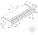
図1は、本発明のコネクタ1を示す斜視図であり、図2は、図1に示すハウジング8を示す斜視図であり、図3は、図1に示すアクチュエーター40を示す斜視図であり、図4は、図1に示すコネクタ1のIV−IV切断線における断面図であり、図5は、図4に示すコネクタ1のアクチュエーター40を回転させた状態を示す断面図である。
1 is a perspective view showing a
本実施形態におけるコネクタ1は、FPCやFFCなどの平型電線が挿入可能なコネクタである。図1、図4に示すように、コネクタ1は、端子60と、アクチュエーター40と、端子60を収納するハウジング8と、を有している。以下、これらの各構成について詳細を説明する。
The
なお、以下の説明においては、図1においてハウジング8の側面(後述する収納部10の側壁12,14)が配置される方向を左右方向(X1、X2方向)とし、ハウジング8の上面(後述する天板16)が配置される方向を上方向(Z1方向)とし、その反対側を下方向(Z2方向)とし、アクチュエーター40が配置される方向を後方(Y2方向)とし、その反対側を前方(Y1方向)とする。なお、Y(Y1、Y2)方向とX(X1、X2)方向は、平面視(Z1方向から見た角度)で直交する。
In the following description, the direction in which the side surface of the housing 8 (
ハウジング8は樹脂などの絶縁体によって形成されており、図2に示すように端子60を収納する収納部10と、左右アクチュエーター保持部30と、を有している。
The
図2、図4に示すように、収納部10は、ハウジング8の左右方向(X1、X2方向)の側面を構成する側壁12,14と、ハウジング8の上面を構成する天板16と、ハウジング8の下面を構成する底部18と、を有している。また、図2に示すように、ハウジング8は、左右の側壁12,14から収納部10の後方(Y2方向)へそれぞれ延びる左右アクチュエーター保持部30を有している。
As shown in FIGS. 2 and 4, the
アクチュエーター保持部30は、アクチュエーター40を、左右のアクチュエーター保持部30の間に保持する部分である。図2に示すように、アクチュエーター保持部30は、アクチュエーター40側に突出する第2の仮止め部32と第2の凸部34を有しているが、それらの詳細な構成については、説明の便宜上後述する。
The
また、ハウジング8は図4に示すように、後方(Y2方向)に、端子60が挿入される開口20が設けられ、前方(Y1方向)には図示しない平型電線が挿入される開口22が設けられている。
4, the
アクチュエーター40は、端子60を弾性変形させる部材であり、例えば樹脂からなる。アクチュエーター40は、図2、図4に示すように左右アクチュエーター保持部30の間に配置される。
The
アクチュエーター40は、図3、図4に示すようにカム部46と、操作部48と、前後方向(Y1、Y2方向)に貫通する孔部50と、アクチュエーター保持部30側(X1、X2方向側)に突出する第1の仮止め部42と、第1の凸部44と、を有している。以下、アクチュエーター40の各構成について、端子60の構成と併せて説明するが、第1の仮止め部42と、第1の凸部44の詳細な構成については、説明の便宜上後述する。
3 and 4, the
図4に示すように、端子60は、上下方向(Z1,Z2方向)に延びる基部62と、基部62の上端62aから後方(Y2方向)に延びる棒状の後上ビーム64と、基部62の上端62aから前方(Y1方向)に延びる棒状の前上ビーム68と、基部62の下端62bから後方(Y2方向)に延びる棒状の後下ビーム74と、基部62の下端62bから前方(Y1方向)に延びる棒状の前下ビーム78と、を備えている。
As shown in FIG. 4, the terminal 60 includes a base 62 extending in the vertical direction (Z1 and Z2 directions), a rod-shaped rear
基部62は、上方のビーム(後上ビーム64、前上ビーム68)と下方のビーム(後下ビーム74、前下ビーム78)を接続する部分である。なお、基部62と上方のビーム(後上ビーム64、前上ビーム68)との境界(基部62の上下方向に延びる部分の上端)を上端62aとし、基部62と下方のビーム(後下ビーム74、前下ビーム78)との境界(基部62の上下方向に延びる部分の下端)を下端62bとする。
The
また、基部62の上方には、上方(Z1方向)に突出する爪部63が形成されている。この爪部63が、図4に示すようにハウジング8の天板16に引っ掛かることにより、端子60はハウジング8に固定される。
Further, a
後上ビーム64は、アクチュエーター40のカム部46により上方(Z1方向)に押し上げられる部分である。後上ビーム64は、アクチュエーター40に設けられた孔部50に嵌っている。
The rear
後下ビーム74は、後上ビーム64の下方(Z2方向)に位置し、後上ビーム64と上下方向(Z1,Z2方向)で向き合っている。後下ビーム74は、下面74bが前後方向(Y1、Y2方向)に真っすぐに延在する部分であるストレート部分74aと、上方(Z1方向)に突出する凸状のストッパー75と、外部の図示しない回路基板に固定される固定部76と、を有している。
The rear lower beam 74 is located below the rear upper beam 64 (Z2 direction) and faces the rear
ストッパー75は、ストレート部分74aの後方(Y2方向)に設けられている。ストッパー75は、アクチュエーター40のカム部46の後方(Y2方向)に位置し、ストッパー75の前面75aにカム部46の後端(下端)46aが位置している。
The
固定部76は、ストッパー75よりも後方(Y2方向)に設けられている。固定部76は、ストレート部分74aの後端74a1から下方(Z2方向)に湾曲した形状であり、固定部76は、ハウジング8の底部18の後端18bよりも後方(Y2方向)に位置している。
The fixing
また、固定部76の下面76aは、底部18の下面18dよりも下方(Z2方向)に位置する。このため、固定部76の前面76bは底部18の後端18bの後方(Y2方向)に位置し、端子部60の前方向(Y1方向)への動きを規制する。また、固定部76の下面76aは図示しない回路基板上に、半田によって固定される。
Further, the
また、図4に示すように、後下ビーム74と、ハウジング8の底部18の上面18aとの間には、隙間Cが設けられていることが好ましい。具体的には、後下ビーム74の下面を下面74b、底部18のうち、後下ビーム74の下方に位置する部分の上面を上面18a1とすると、底部18の上面18a1と後下ビーム74の下面74bとが離間した構成となる。なお、この隙間Cの大きさや位置については、説明の便宜上後述する。
As shown in FIG. 4, a gap C is preferably provided between the rear lower beam 74 and the
また、後下ビーム74と後上ビーム64との間には、アクチュエーター40のカム部46が配置されている。カム部46は、後上ビーム64と後下ビーム74との間で回転することによって、後上ビーム64を上方(Z1方向)に押し上げる部分である。なお、カム部46の回転による作用については、説明の便宜上後述する。
A
前上ビーム68は、後上ビーム64が上方(Z1方向)に押し上げられることにより下方(Z2方向)に傾いて平型電線に接触するビームである。前上ビーム68は、下方(Z2方向)に突出する接触点68aを有している。接触点68aは、ハウジング8内に図示しない平型電線が挿入されて、カム部46が後上ビーム64を上方に押し上げることにより、平型電線の上面に接触する。
The front
前下ビーム78は、前上ビーム68との間に平型電線を挟むビームである。前下ビーム78は、上方(Z1方向)に突出した接触点78aを有している。接触点78aは、ハウジング8内に図示しない平型電線が挿入されることにより、平型電線の下面に接触する。
The front
前下ビーム78の下面78bは、ハウジング8の底部18の上面18aに接触している。下面78bの前端を前端78b1とし、前下ビーム78の前端を前端78cとすると、前端78b1は前端78cよりも後方(Y2方向)側に位置し、接触点78aは、前端78b1よりも後方(Y2方向)側に位置している。
The
なお、本実施形態における「前端78b1」とは、前下ビーム78の下面78bのうち、底部18の上面18aに接する部分の前端を示す。すなわち、前端78b1は、下面78bが底部18の上面18aに接する部分と、下面78bが底部18の上面18aから離れる部分との境界となる。
The “front end 78b1” in the present embodiment indicates a front end of a portion of the
次いで、端子60の後上ビーム64が、アクチュエーター40のカム部46によって上方(Z1方向)に押し上げられた際の、端子60の作用について、詳細を説明する。作業者が図4に示す状態のアクチュエーター40の操作部48を後方(Y2方向)に倒すことにより、図5に示すようにカム部46が後上ビーム64と後下ビーム74との間で回転する。
Next, the operation of the terminal 60 when the rear
カム部46の後端46aから前端46bまでの幅は、後上ビーム64と後下ビーム74の間隔よりも大きい。このため、カム部46が後端46aを支点として回転すると、前端46bが上方(Z1方向)に移動して、後上ビーム64を上方(Z1方向)に押し上げる。
The width from the
このように後上ビーム64が上方(Z1方向)に押し上げられることにより、前上ビーム68に対し、基部62の上端62aを支点として下方(Z2方向)に押下げる力が作用する。これにより、図4、5に示すように前上ビーム68は下方(Z2方向)に傾く。
As the rear
また、後上ビーム64が上方(Z1方向)に押し上げられる力が基部62を介して後下ビーム74に伝わる。この際、後下ビーム74の固定部76の下面76aは図示しない回路基板に固定されているため、後下ビーム74を上方(Z1方向)に持ち上げる力は、固定部76よりも前方(Y1方向)の部分に作用する。このため、後下ビーム74は、固定部76の下面76aが支点として固定された状態で、基部62の下端62bを作用点として上方(Z1方向)に反る。
Further, the force that pushes the rear
同様に、前下ビーム78にも、カム部46により後上ビーム64が上方(Z1方向)に押し上げられることにより、端子60全体に反時計回りのモーメント(図4、5において反時計回り)が作用する。しかし、固定部76は図示しない回路基板に固定されているため、基部62は後方向(Y2方向)に傾く。これにより、前下ビーム78と後下ビーム74は上方(Z1方向)に湾曲する(反る)。
Similarly, also in the front
これにより、前下ビーム78の前方(Y1)側は、下方(Z2方向)側に押下がり、前下ビーム78は、下面78bの前端78b1を支点として、基部62の下端62b側が上方(Z1方向)に湾曲した状態となる。
As a result, the front (Y1) side of the front
このように、本実施形態におけるコネクタ1は、後上ビーム64がカム部46により上方(Z1方向)に押し上げられることで、基部62の下端62bの下面62cが、前下ビーム78の下面78bの前端78b1及び後下ビーム74の固定部76の下面76aよりも上方(Z1方向)に位置するように湾曲する。
As described above, in the
これにより、端子60の下方のビーム(後下ビーム74、前下ビーム78)は、前下ビーム78の下面78bの前端78b1と後下ビーム74の固定部76を支点として、上方(Z1)方向に湾曲する。
Accordingly, the beam below the terminal 60 (the rear lower beam 74 and the front lower beam 78) is directed upward (Z1) with the front end 78b1 of the
このため、コネクタ1は、本構成を有さないコネクタと比べ、後下ビーム74のうち、下面78bの前端78b1と後下ビーム74の固定部76との間の部分の位置が上方(Z1方向)側となる。また、前下ビーム78の接触点78aは前端78b1よりも後方(Y2)側に位置するため、この湾曲により、接触点78aの位置は本構成を有さないコネクタと比べ上方(Z1方向)側となる。
For this reason, in the
よって、コネクタ1の前下ビーム78の接触点78aと、前上ビーム68の接触点68aとの間隔は、本構成を有さないコネクタと比べて小さくなる。このため、平型電線に対する、前上ビーム68と前下ビーム78による接圧が大きくなり、コネクタ1により平型電線を安定して固定することができる。
Therefore, the distance between the
また、本実施形態におけるコネクタ1は、このような構成を有することにより、コネクタ1を小型化しても、平型電線に対する接圧を保つことができる。このため、コネクタ1の小型化を実現することができる。
Moreover, the
また、本実施形態におけるコネクタ1は、図5に示すように後下ビーム74の固定部76の下面76aが図示しない回路基板に固定され、コネクタ60は爪部63によりハウジング8に固定されている。このため、後上ビーム64が上方(Z1方向)に押し上げられることで端子60全体に反時計回りのモーメント(図4、5において反時計回り)が作用すると、このモーメントは爪部63またはその近傍においてハウジング8に加えられる。
Further, in the
これにより、ハウジング8の底部18の後端18bが、ハウシングの底部18の前端18cよりも上方(Z1方向)に位置するように傾斜する。本実施形態におけるコネクタ1は、後下ビーム74と、ハウジング8の底部18の上面18aとの間に隙間Cが設けられているため、このハウジング8の傾斜は、隙間Cにより許容される。
Accordingly, the
なお、本実施形態における隙間Cの後端は、後下ビーム74のストレート部分74aの後端74a1と底部18の上面18a1の間の部分となり、隙間Cには、後下ビーム74の湾曲した部分(固定部76の前面76bからストレート部分74aの後端74a1の間の湾曲部分)は含まれない。よって、隙間Cは、ストレート部分74aの後端74a1から、その前方(Y1方向側)にかけて形成されている。なお、隙間Cは、少なくともストレート部分74aの後端74a1と底部18の上面18a1の間に設けられていればよい。
In this embodiment, the rear end of the gap C is a portion between the rear end 74a1 of the straight portion 74a of the rear lower beam 74 and the upper surface 18a1 of the
ハウジング8の傾斜と隙間Cの関係について具体的に説明すると、ハウジング8の底部18が傾斜することにより、底部18の上面18aの後端18a2側が上方に移動する。ここで、隙間Cが設けられていることにより、底部18の上面18aは隙間Cを埋めるように傾斜することができる。このため、本実施形態におけるコネクタ1は、隙間Cが設けられていないコネクタと比べ、底部18の上面18aが後下ビーム74の下面74bに接触することによる、底部18の傾斜への規制が緩和される。このため、ハウジング8の傾斜を大きくすることができる。
The relationship between the inclination of the
このようにハウジング8の傾斜が大きくなることにより、後上ビーム64とハウジング8が接触することによる、後上ビーム64の傾斜への規制が緩和される。このため、本構成を有さないコネクタと比べ、後上ビーム64と前上ビーム68の傾斜を大きくすることができる。
By increasing the inclination of the
また、後上ビーム64と前上ビーム68の傾斜が大きくなることにより、基部62を介して後下ビーム74と前下ビーム78へ作用する力も大きくなる。さらに、隙間Cが設けられていることにより、後下ビーム74の後端74a1が底部18の上面18a1に接することによる、後下ビーム74の湾曲への規制が緩和される。
Further, since the inclination of the rear
このため、基部62の下端62bの下面62cと、前下ビーム78の下面78bの前端78b1及び後下ビーム74の固定部76の下面76aとの高さの差が、本構成を有さない構成の場合と比べて大きくなる。すなわち、前下ビーム78と後下ビーム74が大きく湾曲する。
Therefore, the difference in height between the
このため、本発明のコネクタ1は、本構成を有さないコネクタと比べて、コネクタ1の前下ビーム78の接触点78aと、前上ビーム68の接触点68aとの間隔を、より小さくすることができる。このため、コネクタ1により平型電線を安定して固定することができるとともに、コネクタ1の小型化を実現することができる。
For this reason, in the
なお、隙間Cは、図5に示すように、少なくともハウジングの底部18の後端18bよりも前方から、カム部46と基部62の下端62bとの間まで延びていることが好ましい。隙間Cがこのような長さで延びていることにより、ハウジング8の傾斜に対する規制が緩和されやすくなる。
As shown in FIG. 5, the gap C preferably extends at least from the front of the
このため、ハウジング8の傾斜を大きくすることができ、前上ビーム68と後上ビーム64と前下ビーム78と後下ビーム74の湾曲を大きくすることができる。このため、コネクタ1により平型電線を安定して固定することができるとともに、コネクタ1の小型化を実現することができる。
For this reason, the inclination of the
なお、前下ビーム78と後下ビーム74とが湾曲しているとき、後下ビーム74は基部62から後方(Y2方向)かつ下方(Z2方向)に延びている。前下ビーム78,後下ビーム74が湾曲しているときに後下ビーム74とハウジング8の底部18とが干渉するのを避けるために、隙間Cは、基部62の下端62bの後方(Y2方向)側まで延びていることが好ましい。
When the front
具体的には、隙間Cの前端が、基部62の下端62bよりも後方(Y2方向)に位置し、かつ、下端62bに近ければ近いほど好ましい。このような構成を有することにより、ハウジング8の傾斜を最大限大きくすることができ、前上ビーム68と後上ビーム64と前下ビーム78と後下ビーム74の湾曲を大きくすることができる。
Specifically, it is preferable that the front end of the gap C is located rearward (Y2 direction) with respect to the
また、隙間Cの前後方向(Y1、Y2方向)の長さや、下方向(Z2方向)の深さは、ハウジング8の強度と、各ビームの望ましい湾曲幅との兼ね合いから適宜決定すればよい。
Further, the length of the gap C in the front-rear direction (Y1, Y2 direction) and the depth in the downward direction (Z2 direction) may be appropriately determined from the balance between the strength of the
なお、前下ビーム78の下面78bと、後下ビーム74の下面74bは、その前後方向(Y1、Y2方向)の断面図において、直線形状であることが好ましい。このような構成を有することにより、各ビーム(前下ビーム78、後下ビーム74)が均一に湾曲しやすくなる。
Note that the
なお、隙間Cは、図5に示すように、ハウジング8の底部18の上面18aが凹むことにより構成されていることが好ましい。このような構成を有することにより、後下ビーム74の下面74bの直線形状と強度を保ったまま、本発明の効果を得ることができる。
In addition, as shown in FIG. 5, it is preferable that the clearance gap C is comprised when the
なお、隙間Cは、底部18の上面18aが凹むことにより構成されていることが好ましいが、後下ビーム74の下面74bが上方(Z1方向)に凹むことにより構成されたものであってもよい。
Note that the gap C is preferably configured by recessing the
次いで、アクチュエーター40の第1の仮止め部42と第1の凸部44、及び、アクチュエーター保持部30の第2の仮止め部32と第2の凸部34の詳細な構成と、アクチュエーター40をハウジング8に取り付ける際における、これら構成の作用について図面を用いて説明する。
Next, the detailed configuration of the first
図6は、ハウジング8にアクチュエーター40を取り付ける(組み付ける)工程を、図1と同様の方向から見た斜視図であり、図7Aは、図6に示すハウジング8とアクチュエーター40を上方(Z1方向)から見た平面図であり、図7Bは、図7Aに示すハウジング8とアクチュエーター40のVIIB−VIIB切断線における断面図であり、図8Aは、ハウジング8にアクチュエーター40を取り付ける工程を、図7Aと同様の方向から見た平面図であり、図8Bは、図8Aに示すハウジング8とアクチュエーター40のVIIIB−VIIIB切断線における断面図であり、図9は、図3に示すアクチュエーター40のIX領域の部分拡大図である。
FIG. 6 is a perspective view of the step of attaching (assembling) the
なお、アクチュエーター40をハウジング8に組み付ける工程は、カム部46がストッパー75と後上ビーム64との間を通過できるように、アクチュエーター40を配置する工程と、アクチュエーター40を前方(Y1方向)に移動させる工程と、を有する。また、前方(Y1方向)移動させたアクチュエーター40を下方(Z2方向)に移動させることにより、アクチュエーター40は図1、4に示すように、端子60に嵌る。以下、各構成と、各工程における各構成の作用について順次説明する。
The process of assembling the
はじめに、アクチュエーター40の第1の仮止め部42と第1の凸部44、及び、アクチュエーター保持部30の第2の仮止め部32と第2の凸部34の詳細な構成について説明する。
First, detailed configurations of the first
図6、図9に示すように、アクチュエーター40の左右方向(X1、X2方向)の側面41には、アクチュエーター保持部30側に突出する第1の仮止め部42と第1の凸部44とが設けられている。
As shown in FIGS. 6 and 9, on the
図9に示すように、第1の仮止め部42は、アクチュエーター40の側面41からアクチュエーター保持部30側(図9においてはX1方向側)に突出した凸状の構成を有している。第1の仮止め部42は、アクチュエーター40が組み付けられる過程でアクチュエーター保持部30の第2の仮止め部32に掛止することにより、アクチュエーター40の後ろ方向(Y2方向)への動きを規制する部分である。
As shown in FIG. 9, the first
第1の仮止め部42の後方(Y2方向側)の面を第1の後面42aとし、前方(Y1方向側)の面を前面42bとすると、前面42bと側面41がなす角度は、第1の後面42aと側面41がなす角度よりも小さいことが好ましい。具体的には、アクチュエーター40を上方向(Z1方向)から見た場合に、前面42bと側面41がなす角度は鋭角となる。
When the rear (Y2 direction side) surface of the first
このような構成を有することにより、第1の仮止め部42の前面42bが第2の仮止め部32に接触することによる、アクチュエーター40の前方(Y1方向)への移動の規制が緩和される。このため、第1の仮止め部42を第2の仮止め部32に掛止させやすくなる。
By having such a configuration, restriction of movement of the
第1の凸部44は、第1の仮止め部42の下方(Z2方向)側に設けられている。第1の凸部44は、アクチュエーター保持部30の第2の凸部34に係合する部分である。第1の凸部44は、アクチュエーター40の側面41からアクチュエーター保持部30側に突出した凸状の構成を有している。
The first
第1の凸部44のアクチュエーター保持部30側の面44c(図9においてはX1方向側の面)は、第1の仮止め部42のアクチュエーター保持部30側の面42cよりもアクチュエーター保持部30側に位置する。
The surface 44c on the
第1の凸部44の上側(Z1方向側)の面を上面44dとすると、上面44dが第1の仮止め部42の面42cとなす角度は、垂直に近いほど好ましい。このような構成を有することにより、第1の凸部44の上面44dが第2の凸部の34の下面34dに掛止しやすくなり、アクチュエーター40の上方向(Z1方向)への位置ずれを防ぐことができる。
If the surface on the upper side (Z1 direction side) of the first
また、図2、図7A、7Bに示すように、アクチュエーター保持部30のアクチュエーター40側の側面には、アクチュエーター40側に突出する第2の仮止め部32と、第2の凸部34とが設けられている。
As shown in FIGS. 2, 7A, and 7B, the
図2に示すように、第2の仮止め部32は、アクチュエーター保持部30からアクチュエーター40側に突出した凸状の構成を有している。第2の仮止め部32は、アクチュエーター40がコネクタに組み付けられる過程でアクチュエーター40の第1の仮止め部42に掛止することにより、アクチュエーター40の後ろ方向(Y2方向)への動きを規制する部分である。
As shown in FIG. 2, the second temporary fixing
図2、図7Aに示すように、第2の仮止め部32のY1方向側の前端を前端(前面)32aとし、前端32aよりも後方(Y2方向)の側面を斜面32bとすると、斜面32bと側壁12,14がなす角度は、ハウジング8を上方向(Z1方向)から見た場合に鋭角であることが好ましい。
As shown in FIGS. 2 and 7A, if the front end of the second temporary fixing
このような構成を有することにより、第1の仮止め部42の前面42bが第2の仮止め部32の斜面32bに接触することによる、アクチュエーター40の前方への移動の規制が緩和される。このため、第1の仮止め部42を第2の仮止め部32に掛止させやすくなる。
By having such a configuration, the restriction of the forward movement of the
次いで、カム部46がストッパー75と後上ビーム64との間を通過できるように、アクチュエーター40を配置する工程と、アクチュエーター40を前方(Y1方向)に移動させる工程における、第1の仮止め部42と第2の仮止め部32の作用について説明する。まず、図6に示すように、アクチュエーター40の第1の仮止め部42の上下方向(Z1、Z2方向)の位置と、端子60が収納されたハウジング8の第2の仮止め部32の上下方向の位置が対応するように位置合わせを行う。
Next, a first temporary fixing portion in the step of arranging the
次いで、図6,7A,7Bに示すように、矢印の方向(Y1方向)にアクチュエーター40を移動させる。そして、図8Aに示すように、第1の仮止め部42の後端(後面)42aを、第2の仮止め部32の前端(前面)32aよりも前方(Y1方向)に配置させる。これにより、図8Bに示すように、カム部46は、端子60のストッパー75よりも前方(Y1方向)且つ上方(Z1方向)で且つ後上ビーム64の下方(Z2方向)に配置される。
Next, as shown in FIGS. 6, 7A, and 7B, the
このようにアクチュエーター40を移動させる際、左右の第2の仮止め部32の斜面32b同士の間隔は、第1の仮止め部42の左右の面42c同士の間隔よりも小さいため、第2の仮止め部32の斜面32bと、第1の仮止め部42の前面42bは接触した状態(接圧が保たれた状態)となる。
When the
このため、第1の仮止め部42の後端42aが、第2の仮止め部32の前端32aよりも前方(Y1方向)に移動するまでの間、アクチュエーター40は、第1の仮止め部42が第2の仮止め部32の斜面32bに入れ込まれた状態となる。この移動の間は、第2の仮止め部32と第1の仮止め部42との間の接圧が加わることにより、アクチュエーター40が湾曲してもよい。
Therefore, until the
そして、図8A,8Bに示すように、第1の仮止め部42の後端42aが、第2の仮止め部32の前端32aよりも前方(Y1方向)に移動することにより、第2の仮止め部32の斜面32bと、第1の仮止め部42の前面42bが離れるため、アクチュエーター40に加えられていた接圧が失われる。
8A and 8B, the
これにより、アクチュエーター40の左右方向(X1,X2方向)の幅は、接圧が加えられる前の幅に戻り、第1の仮止め部42のアクチュエーター保持部30側の面42cは、第2の仮止め部32の斜面32bの後端32b1よりも外側(X1、X2方向側)となる。
As a result, the width in the left-right direction (X1, X2 direction) of the
このため、第1の仮止め部42の後端42aと第2の仮止め部32の前端32aは、図8Aに示すように、平面視(Z1方向から見た平面)で前後方向(Y1,Y2方向)に、少なくとも一部が重なり、第1の仮止め部42の後方(Y2方向)への動きが規制される。
For this reason, as shown in FIG. 8A, the
本実施形態におけるコネクタ1は、以上のように、第1の仮止め部42が第2の仮止め部32の前方(Y1方向)にあるときに、第1の仮止め部42の後方(Y2方向)向への動きが規制される。
As described above, the
このため、アクチュエーター40のカム部46が、端子60のストッパー75と後上ビーム64の間に位置するときの、カム部46の後ろ方向(Y2方向)への動きが規制される。これにより、アクチュエーター40のハウジング8への仮止めの際に、カム部46が端子60から抜けてしまうことが防がれる。
For this reason, when the
なお、本実施形態におけるコネクタ1は、図6、8Aに示すように、第2の仮止め部32の前方(Y1方向)に、天板16の前端16aから第2の仮止め部32の前端32aまで前後方向(Y1,Y2方向)に延びる溝Dが形成されている。この溝Dは、第2の仮止め部32を形成する際に設けられる凹みである。
In addition, as shown in FIGS. 6 and 8A, the
第2の仮止め部32は、ハウジング8を成形する際に、第2の仮止め部32の前端32aの所望の位置に合わせて図示しない金型を配置することにより形成される。この際、前端32aの位置に合わせて金型の後端(図のY2方向側の端)が配置されるため、成形された天板16には、金型の位置に対応して、天板16の前端16aから第2の仮止め部32の前端32aまで前後方向に延びる溝Dが形成される。
When the
また、溝Dはこのように形成されることにより、天板16を前方(Y1方向)から見た場合に、溝Dの内側に第2の仮止め部32の前端32aが見える構成となる。
Further, by forming the groove D in this way, the
本実施形態におけるコネクタ1は、このような構成を有することにより、第2の仮止め部32を、第2仮止め部32の前端32aを形成する金型と、第2の仮止め部32の斜面32bを形成する金型との2つにより形成可能である。従来はハウジング8に仮止め部を形成するためには、少なくとも3つ以上の金型が必要であった。一方、本実施形態のコネクタ1においては、上記の構成を有することにより、必要な金型の種類と、仮止めに必要な構成の成形における工程を簡略化することができる。このため、コネクタ1の形成における費用を抑えることができる。
The
また、本実施形態におけるコネクタ1は、第2の仮止め部32を、前後方向(Y1,Y2方向)に延在する1つの金型を用いて形成可能である。このため、ハウジングの開口20、22を形成するための金型を利用して、第2の仮止め部32を形成することができる。このため、第2の仮止め部32形成における工程や金型の種類を簡略化することができる。
Moreover, the
また、本実施形態におけるコネクタ1は、第2の仮止め部32が天板16と一体形成されるため、例えば棒状や凸状の仮止め部が別途形成されたコネクタと比べ、第2の仮止め部32の強度を高めることができる。
Further, in the
次いで、図1、図4に示すように、アクチュエーター40のカム部46を端子60のストッパー75の前方(Y1方向)に配置する際における、第1の凸部44と第2の凸部34の作用について説明する。
Next, as shown in FIGS. 1 and 4, when the
カム部46をストッパー75の前方(Y1方向)に配置するには、図8A、図8Bに示すように、カム部46が、端子60のストッパー75と後上ビーム64の間に位置した状態から、図4に示すように、カム部46の後端46aがストッパー75の前面75aに位置するまでアクチュエーター40を下方(Z2方向)に押下げる。
In order to arrange the
このようにアクチュエーター40を移動させる際、左右の第2の凸部34同士の間隔は、左右の第1の凸部44の面44c同士の間隔よりも小さいため、第2の凸部34と、第1の凸部44の面44cは接触した状態(接圧が保たれた状態)となる。
When the
このため、図9に示す第1の凸部44の上面44dが、図1、図2に示す第2の凸部の34の下面34dよりも下方(Z2方向)に移動するまでの間、アクチュエーター40に接圧が加えられた状態となる。
For this reason, an actuator is used until the
そして、図1、図4に示すように、第1の凸部44の上面44dが、第2の凸部の34の下面34dよりも下方(Z2方向)に移動することにより、第1の凸部44の面44cと、第2の凸部34のアクチュエーター40側の面34cが離れるため、アクチュエーター40に加えられていた接圧が失われる。
As shown in FIGS. 1 and 4, the
これにより、アクチュエーター40の左右方向(X1,X2方向)の幅は、接圧が加えられる前の幅に戻り、第1の凸部44のアクチュエーター保持部30側の面44cは、第2の凸部34の面34cよりも外側(X1、X2方向側)となる。このため、第1の凸部44の上面44dと第2の凸部の34の下面34dは、図4に示すように上下方向(Z1,Z2方向)で少なくとも一部が重なる。
Thereby, the width in the left-right direction (X1, X2 direction) of the
本実施形態におけるコネクタ1は、第1の凸部44が、アクチュエーター保持部30の第2の凸部34に係合することにより、アクチュエーター40の上方向(Z1方向)への動きが規制される。これにより、アクチュエーター40のカム部46が定位置(カム部46の後端46aがストッパー75の前面75aに位置する状態)からずれることが防がれる。
In the
また、本実施形態におけるコネクタ1は、本構成を有さないコネクタと異なり、アクチュエーター40の定位置からずれ防止のための部品が不要である。このため、コネクタ1の構成の簡素化を実現することができる。また、コネクタ1の構成を簡素化できるため、アクチュエーター40保持用の部品を別途取り付ける工程や、部品の費用が不要となる。
Further, the
以上、本発明の実施形態を説明してきたが、本発明は、上述した実施形態には限られない。例えば、上述した実施形態で説明した構成は、実質的に同一の構成、同一の作用効果を奏する構成、又は同一の目的を達成することができる構成により置き換えてもよい。 As mentioned above, although embodiment of this invention was described, this invention is not restricted to embodiment mentioned above. For example, the configuration described in the above-described embodiment may be replaced by a configuration that has substantially the same configuration, a configuration that exhibits the same operational effects, or a configuration that can achieve the same purpose.
例えば、第1の仮止め部42と第2の仮止め部32の位置は、図2,6乃至9に示した位置に限られず、カム部46の所望の位置に応じて適宜調整することができる。例えば、第2の仮止め部32の位置は溝Dの深さにより調整可能である。
For example, the positions of the first
また、第1の仮止め部42と第2の仮止め部32は、凸状の構成に限られず、互いが係合するものであれば、一方が凹状の構成であってもよい。
Moreover, the 1st temporary fix | stop
また、本実施形態に係るコネクタ1は、アクチュエーター保持部30が凸状の構成を有していなくてもよい。具体的には、アクチュエーター保持部30とアクチュエーター40の係合箇所は、互いに段差が係合する構成であればよく、凸状の第1の凸部44と第2の凸部34に代えて、凸状の構成と、凹状の構成が係合するものであってもよい。
Further, in the
さらに、第1の凸部44と第2の凸部34の位置は、図に示した位置に限られず、カム部46の所望の位置に応じて適宜調整することができる。例えば、カム部46の所望の位置に応じて第2の凸部34の上下方向の幅を適宜調整することができる。
Furthermore, the positions of the first
なお、本実施形態に係るコネクタ1においては、図4,5に示すように一種類の端子60のみが例示されているが、端子60の構成は図4,5に示された構成のみに限られず、その他の構成であってもよい。例えば、端子60は、前下ビーム78に、コネクタ1の外部の図示しない回路基板に固定するための固定部を含む構成であってもよい。
In the
1 コネクタ、8 ハウジング、10 収納部、12、14 側壁、16 天板、16a 前端、18 底部、18a 上面、18a1 上面、18b 後端、18c 前端、18d 下面、30 アクチュエーター保持部、32 第2の仮止め部、32a 前端、32b 斜面、32b1 後端、34 第2の凸部、34d 下面、40 アクチュエーター、42 第1の仮止め部、42a 後端、42b 前面、42c 面、44 第1の凸部、44c 面、44d 上面、46 カム部、46a 後端、46b 前端、48 操作部、50 孔部、60 端子、62 基部、62a 上端、62b 下端、62c 下面、64 後上ビーム、68 前上ビーム、74 後下ビーム、74a ストレート部分、74a1 後端、74b 下面、75 ストッパー、76 固定部、76a 下面、76b 前面、78 前下ビーム、78a 接触点、78b 下面、78b1 前端、78c 前端、C 隙間、D 溝。
DESCRIPTION OF
Claims (6)
前記端子は、
上下方向に延びる基部と、
前記基部の上端から後方に延びる後上ビームと、
前記後上ビームが上方に押し上げられることにより下方に傾いて前記平型電線に接触する、前記基部の上端から前方に延びる前上ビームと、
前記基部の下端から後方に延びる後下ビームと、
前記基部の下端から前方に延びる前下ビームと、
を備え、
前記アクチュエーターは、前記後下ビームと前記後上ビームとの間に配置されて前記後上ビームを上方に押し上げるカム部を含み、
前記後下ビームは、前記後下ビームの後端に、外部の回路基板に固定するための固定部を含み、
前記前下ビームは、
前記平型電線に接触する、上方に突出した接触点と、
前記ハウジングの底部の上面に接触する前下ビームの下面の前端と、
を含み、
前記接触点は、前記前下ビームの下面の前端よりも後方側に位置し、
前記前下ビームと前記後下ビームは、前記後上ビームが上方に押し上げられることにより、前記前下ビームの下面の前端と前記固定部を支点として上方に湾曲し、
前記ハウジングは、前記後上ビームが上方に押し上げられることにより、前記ハウジングの底部の後端が、前記ハウシングの底部の前端よりも上方に位置するように傾斜し、
前記ハウジングの底部の上面後端と前記後下ビームとの間に、前記ハウジングの傾斜を許容する隙間が設けられている
ことを特徴とするコネクタ。 A connector having a terminal, an actuator, and a housing for housing the terminal, into which a flat electric wire can be inserted,
The terminal is
A base extending in the vertical direction;
A rear upper beam extending rearward from the upper end of the base;
A front upper beam extending forward from an upper end of the base, wherein the rear upper beam is pushed upward to incline downward and contact the flat electric wire;
A rear lower beam extending rearward from the lower end of the base;
A front lower beam extending forward from the lower end of the base;
With
The actuator includes a cam portion disposed between the rear lower beam and the rear upper beam to push the rear upper beam upward,
The rear lower beam includes a fixing portion for fixing to an external circuit board at a rear end of the rear lower beam,
The front lower beam is
A contact point that protrudes upward and contacts the flat wire;
The front end of the lower surface of the front lower beam contacting the upper surface of the bottom of the housing;
Including
The contact point is located behind the front end of the lower surface of the front lower beam,
The rear lower beam and the front lower beam, by the upper rear beam is pushed upward, curved upward to the front end and the fixed portion of the lower surface of the lower front beam as a fulcrum,
The housing is inclined such that the rear end of the bottom of the housing is positioned higher than the front end of the bottom of the housing as the rear upper beam is pushed upward.
The connector is characterized in that a gap allowing inclination of the housing is provided between the rear upper surface of the bottom of the housing and the rear lower beam .
前記隙間が、少なくとも前記ハウジングの底部の後端から、前記カムと前記基部の下端の間まで延びている、
ことを特徴とするコネクタ。 The connector according to claim 1 ,
The gap extends at least from the rear end of the bottom of the housing to between the cam and the lower end of the base,
A connector characterized by that.
前記隙間が、前記ハウジングの底部の上面が凹んでいることにより構成されている、
ことを特徴とするコネクタ。 The connector according to claim 1 or 2 , wherein
The gap is configured by a concave upper surface of the bottom of the housing.
A connector characterized by that.
前記ハウジング内に収納される端子と、
アクチュエーターと、
を備え、
前記ハウジングは、
前記端子を収納する、前記ハウジングの左右の側面を構成する左右の側壁と前記ハウジングの上面を構成する天板とを有する収納部と、
前記左右の側壁から前記収納部の後方へそれぞれ延びる左右のアクチュエーター保持部と、
を含み、
前記端子は、
後方に延びる後上ビームと、
前記後上ビームの下方に位置して後方に延びる、上方に突出する凸状のストッパーを有する後下ビームと、
を含み、
前記アクチュエーターは、
前記左右アクチュエーター保持部の間に配置され、
前記後下ビームと前記後上ビームとの間に配置されるカム部と前記左右のアクチュエーター保持部側に突出する左右の第1の仮止め部とを含み、
前記アクチュエーター保持部は、前記アクチュエーター側に突出する第2の仮止め部を含み、
前記第2の仮止め部は、前記第1の仮止め部が前記第2の仮止め部の前方にあるときに、前記第1の仮止め部の後方向への動きを規制し、
前記第2の仮止め部の前方に、前記天板の前端から前記第2の仮止め部の前端まで延びる溝が形成されている、
ことを特徴とするコネクタ。 A housing;
A terminal housed in the housing;
An actuator,
With
The housing is
A storage unit that stores the terminals, and includes left and right side walls that form the left and right side surfaces of the housing, and a top plate that forms the top surface of the housing;
Left and right actuator holding portions respectively extending from the left and right side walls to the rear of the storage portion;
Including
The terminal is
A rear upper beam extending rearward;
A rear lower beam having a convex stopper protruding upward and positioned rearwardly of the rear upper beam;
Including
The actuator is
Arranged between the left and right actuator holders;
A cam portion disposed between the rear lower beam and the rear upper beam, and left and right first temporary fixing portions projecting to the left and right actuator holding portions;
The actuator holding portion includes a second temporary fixing portion protruding to the actuator side,
The second temporary fixing portion regulates the backward movement of the first temporary fixing portion when the first temporary fixing portion is in front of the second temporary fixing portion.
A groove extending from the front end of the top plate to the front end of the second temporary fixing part is formed in front of the second temporary fixing part.
A connector characterized by that.
前記天板を前方から見た場合に、前記溝の内側に前記第2の仮止め部の前端が見えることを特徴とするコネクタ。 The connector according to claim 4 ,
When the top plate is viewed from the front, the front end of the second temporary fixing portion can be seen inside the groove.
前記ハウジング内に収納される端子と、
アクチュエーターと、
を備え、
前記ハウジングは、
前記端子を収納する、前記ハウジングの左右の側面を構成する左右の側壁と前記ハウジングの上面を構成する天板とを有する収納部と、
前記左右の側壁から前記収納部の後方へそれぞれ延びる左右のアクチュエーター保持部と、
を含み、
前記端子は、
後方に延びる後上ビームと、
前記後上ビームの下方に位置して後方に延びる、上方に突出する凸状のストッパーを有する後下ビームと、
を含み、
前記アクチュエーターは、
前記左右アクチュエーター保持部の間に配置されており、
前記後下ビームと前記後上ビームの間の、前記ストッパーの前方に配置されるカム部と、前記アクチュエーター保持部側に突出する第1の凸部と、を含み、
前記アクチュエーター保持部は前記アクチュエーター側に突出する第2の凸部を含み、
前記第1の凸部が前記第2の凸部に係合することにより、前記アクチュエーターの上方向の動きが規制されており、
前記第2の凸部は、前後方向に沿った鉛直面を切断面とする前記ハウジングの断面視において、前記端子の前記ストッパーの上面の上方に位置し且つ前記ストッパの前面より前方に伸びている
ことを特徴とするコネクタ。 A housing;
A terminal housed in the housing;
An actuator,
With
The housing is
A storage unit that stores the terminals, and includes left and right side walls that form the left and right side surfaces of the housing, and a top plate that forms the top surface of the housing;
Left and right actuator holding portions respectively extending from the left and right side walls to the rear of the storage portion;
Including
The terminal is
A rear upper beam extending rearward;
A rear lower beam having a convex stopper protruding upward and positioned rearwardly of the rear upper beam;
Including
The actuator is
It is disposed between the left and right actuator holding parts,
A cam portion disposed in front of the stopper between the rear lower beam and the rear upper beam, and a first convex portion protruding toward the actuator holding portion side ,
The actuator holding portion includes a second convex portion protruding toward the actuator side,
The upward movement of the actuator is restricted by engaging the first convex portion with the second convex portion ,
The second convex portion is positioned above the upper surface of the stopper of the terminal and extends forward from the front surface of the stopper in a sectional view of the housing with a vertical plane along the front-rear direction as a cut surface. A connector characterized by that.
Priority Applications (6)
| Application Number | Priority Date | Filing Date | Title |
|---|---|---|---|
| JP2013273021A JP6208008B2 (en) | 2013-12-27 | 2013-12-27 | connector |
| TW103145500A TWI589064B (en) | 2013-12-27 | 2014-12-25 | Connector |
| CN201480061869.5A CN105723573B (en) | 2013-12-27 | 2014-12-26 | Connector |
| US15/037,014 US9698510B2 (en) | 2013-12-27 | 2014-12-26 | Connector for securing a flat cable |
| KR1020167019949A KR101832645B1 (en) | 2013-12-27 | 2014-12-26 | Connector |
| PCT/JP2014/084491 WO2015099117A1 (en) | 2013-12-27 | 2014-12-26 | Connector |
Applications Claiming Priority (1)
| Application Number | Priority Date | Filing Date | Title |
|---|---|---|---|
| JP2013273021A JP6208008B2 (en) | 2013-12-27 | 2013-12-27 | connector |
Publications (2)
| Publication Number | Publication Date |
|---|---|
| JP2015128010A JP2015128010A (en) | 2015-07-09 |
| JP6208008B2 true JP6208008B2 (en) | 2017-10-04 |
Family
ID=53478956
Family Applications (1)
| Application Number | Title | Priority Date | Filing Date |
|---|---|---|---|
| JP2013273021A Active JP6208008B2 (en) | 2013-12-27 | 2013-12-27 | connector |
Country Status (6)
| Country | Link |
|---|---|
| US (1) | US9698510B2 (en) |
| JP (1) | JP6208008B2 (en) |
| KR (1) | KR101832645B1 (en) |
| CN (1) | CN105723573B (en) |
| TW (1) | TWI589064B (en) |
| WO (1) | WO2015099117A1 (en) |
Families Citing this family (3)
| Publication number | Priority date | Publication date | Assignee | Title |
|---|---|---|---|---|
| JP6780352B2 (en) * | 2016-08-04 | 2020-11-04 | I−Pex株式会社 | Electrical connector |
| JP2020107507A (en) * | 2018-12-27 | 2020-07-09 | モレックス エルエルシー | Connector assembly |
| CN111834771B (en) * | 2020-06-20 | 2021-11-30 | 青岛恩利旺精密工业有限公司 | FPC connector and connecting method thereof |
Family Cites Families (15)
| Publication number | Priority date | Publication date | Assignee | Title |
|---|---|---|---|---|
| JPH09283236A (en) * | 1996-04-09 | 1997-10-31 | Sumitomo Wiring Syst Ltd | Connector for flexible printed circuit board |
| JP3047862B2 (en) | 1997-07-08 | 2000-06-05 | オムロン株式会社 | connector |
| TW443641U (en) | 2000-02-02 | 2001-06-23 | Hon Hai Prec Ind Co Ltd | Electrical connector |
| JP4054741B2 (en) * | 2003-09-26 | 2008-03-05 | 日本圧着端子製造株式会社 | ZIF connector for low profile FPC |
| JP4578931B2 (en) * | 2004-10-18 | 2010-11-10 | 第一電子工業株式会社 | connector |
| JP4437982B2 (en) * | 2005-08-08 | 2010-03-24 | ヒロセ電機株式会社 | Electrical connector for flat cable |
| JP4576349B2 (en) * | 2006-03-24 | 2010-11-04 | ヒロセ電機株式会社 | Flat circuit board electrical connector |
| JP4858249B2 (en) * | 2007-03-19 | 2012-01-18 | オムロン株式会社 | connector |
| JP4330084B2 (en) * | 2007-06-12 | 2009-09-09 | ヒロセ電機株式会社 | Flat conductor electrical connector |
| JP4992707B2 (en) * | 2007-12-28 | 2012-08-08 | オムロン株式会社 | connector |
| JP5498733B2 (en) * | 2009-07-16 | 2014-05-21 | モレックス インコーポレイテド | connector |
| JP5739104B2 (en) * | 2010-01-29 | 2015-06-24 | モレックス インコーポレイテドMolex Incorporated | connector |
| JP5123976B2 (en) * | 2010-04-08 | 2013-01-23 | パナソニック株式会社 | connector |
| JP4897917B1 (en) | 2010-09-03 | 2012-03-14 | 京セラエルコ株式会社 | connector |
| JP4945006B1 (en) * | 2011-09-26 | 2012-06-06 | イリソ電子工業株式会社 | connector |
-
2013
- 2013-12-27 JP JP2013273021A patent/JP6208008B2/en active Active
-
2014
- 2014-12-25 TW TW103145500A patent/TWI589064B/en active
- 2014-12-26 US US15/037,014 patent/US9698510B2/en active Active
- 2014-12-26 KR KR1020167019949A patent/KR101832645B1/en active IP Right Grant
- 2014-12-26 CN CN201480061869.5A patent/CN105723573B/en active Active
- 2014-12-26 WO PCT/JP2014/084491 patent/WO2015099117A1/en active Application Filing
Also Published As
| Publication number | Publication date |
|---|---|
| TW201541725A (en) | 2015-11-01 |
| US9698510B2 (en) | 2017-07-04 |
| KR101832645B1 (en) | 2018-02-26 |
| KR20160102502A (en) | 2016-08-30 |
| CN105723573A (en) | 2016-06-29 |
| JP2015128010A (en) | 2015-07-09 |
| WO2015099117A1 (en) | 2015-07-02 |
| CN105723573B (en) | 2018-02-16 |
| TWI589064B (en) | 2017-06-21 |
| US20160301151A1 (en) | 2016-10-13 |
Similar Documents
| Publication | Publication Date | Title |
|---|---|---|
| JP3225112U (en) | Connection terminal and connection assembly | |
| JP5498733B2 (en) | connector | |
| JP5765462B1 (en) | Electrical connector | |
| KR101226418B1 (en) | Terminal fitting | |
| JP2008130244A (en) | Connector | |
| KR101331295B1 (en) | Electric connector for circuit substrate | |
| JP6686140B2 (en) | connector | |
| JP6208008B2 (en) | connector | |
| JP2007141725A (en) | Connector | |
| JP4760686B2 (en) | Lock structure | |
| JP6944331B2 (en) | Connector and connector assembly. | |
| JP5186289B2 (en) | Wire harness retaining clip | |
| JP4684191B2 (en) | connector | |
| JP6727580B2 (en) | Connector terminal holding member, connector, and electrical connection device | |
| JP2010118255A (en) | Electric connector assembly | |
| JP6861582B2 (en) | connector | |
| JP4168911B2 (en) | connector | |
| JP5518641B2 (en) | Connectors and retainers | |
| JP7042580B2 (en) | Connector, housing, cover body, and wire harness with connector | |
| JP6680189B2 (en) | Wire cover and connector | |
| JP4808537B2 (en) | Dip connector | |
| JP2020102333A (en) | Split connector | |
| JP4407528B2 (en) | Lever type connector | |
| JP6928506B2 (en) | Connector holder | |
| JP2005347082A (en) | Connector |
Legal Events
| Date | Code | Title | Description |
|---|---|---|---|
| A621 | Written request for application examination |
Free format text: JAPANESE INTERMEDIATE CODE: A621 Effective date: 20160831 |
|
| A131 | Notification of reasons for refusal |
Free format text: JAPANESE INTERMEDIATE CODE: A131 Effective date: 20170509 |
|
| A521 | Request for written amendment filed |
Free format text: JAPANESE INTERMEDIATE CODE: A523 Effective date: 20170808 |
|
| TRDD | Decision of grant or rejection written | ||
| A01 | Written decision to grant a patent or to grant a registration (utility model) |
Free format text: JAPANESE INTERMEDIATE CODE: A01 Effective date: 20170815 |
|
| A61 | First payment of annual fees (during grant procedure) |
Free format text: JAPANESE INTERMEDIATE CODE: A61 Effective date: 20170906 |
|
| R150 | Certificate of patent or registration of utility model |
Ref document number: 6208008 Country of ref document: JP Free format text: JAPANESE INTERMEDIATE CODE: R150 |
|
| R250 | Receipt of annual fees |
Free format text: JAPANESE INTERMEDIATE CODE: R250 |
|
| R250 | Receipt of annual fees |
Free format text: JAPANESE INTERMEDIATE CODE: R250 |
|
| R250 | Receipt of annual fees |
Free format text: JAPANESE INTERMEDIATE CODE: R250 |
|
| R250 | Receipt of annual fees |
Free format text: JAPANESE INTERMEDIATE CODE: R250 |