JP6207599B2 - Patient sleep therapy self-management tool - Google Patents
Patient sleep therapy self-management tool Download PDFInfo
- Publication number
- JP6207599B2 JP6207599B2 JP2015515643A JP2015515643A JP6207599B2 JP 6207599 B2 JP6207599 B2 JP 6207599B2 JP 2015515643 A JP2015515643 A JP 2015515643A JP 2015515643 A JP2015515643 A JP 2015515643A JP 6207599 B2 JP6207599 B2 JP 6207599B2
- Authority
- JP
- Japan
- Prior art keywords
- patient
- information
- therapy
- pressure
- computing device
- Prior art date
- Legal status (The legal status is an assumption and is not a legal conclusion. Google has not performed a legal analysis and makes no representation as to the accuracy of the status listed.)
- Active
Links
Images


Classifications
-
- G—PHYSICS
- G16—INFORMATION AND COMMUNICATION TECHNOLOGY [ICT] SPECIALLY ADAPTED FOR SPECIFIC APPLICATION FIELDS
- G16H—HEALTHCARE INFORMATICS, i.e. INFORMATION AND COMMUNICATION TECHNOLOGY [ICT] SPECIALLY ADAPTED FOR THE HANDLING OR PROCESSING OF MEDICAL OR HEALTHCARE DATA
- G16H80/00—ICT specially adapted for facilitating communication between medical practitioners or patients, e.g. for collaborative diagnosis, therapy or health monitoring
-
- A—HUMAN NECESSITIES
- A61—MEDICAL OR VETERINARY SCIENCE; HYGIENE
- A61B—DIAGNOSIS; SURGERY; IDENTIFICATION
- A61B5/00—Measuring for diagnostic purposes; Identification of persons
- A61B5/48—Other medical applications
- A61B5/4806—Sleep evaluation
- A61B5/4818—Sleep apnoea
-
- A—HUMAN NECESSITIES
- A61—MEDICAL OR VETERINARY SCIENCE; HYGIENE
- A61M—DEVICES FOR INTRODUCING MEDIA INTO, OR ONTO, THE BODY; DEVICES FOR TRANSDUCING BODY MEDIA OR FOR TAKING MEDIA FROM THE BODY; DEVICES FOR PRODUCING OR ENDING SLEEP OR STUPOR
- A61M16/00—Devices for influencing the respiratory system of patients by gas treatment, e.g. mouth-to-mouth respiration; Tracheal tubes
- A61M16/0003—Accessories therefor, e.g. sensors, vibrators, negative pressure
-
- A—HUMAN NECESSITIES
- A61—MEDICAL OR VETERINARY SCIENCE; HYGIENE
- A61M—DEVICES FOR INTRODUCING MEDIA INTO, OR ONTO, THE BODY; DEVICES FOR TRANSDUCING BODY MEDIA OR FOR TAKING MEDIA FROM THE BODY; DEVICES FOR PRODUCING OR ENDING SLEEP OR STUPOR
- A61M16/00—Devices for influencing the respiratory system of patients by gas treatment, e.g. mouth-to-mouth respiration; Tracheal tubes
- A61M16/06—Respiratory or anaesthetic masks
-
- G—PHYSICS
- G16—INFORMATION AND COMMUNICATION TECHNOLOGY [ICT] SPECIALLY ADAPTED FOR SPECIFIC APPLICATION FIELDS
- G16H—HEALTHCARE INFORMATICS, i.e. INFORMATION AND COMMUNICATION TECHNOLOGY [ICT] SPECIALLY ADAPTED FOR THE HANDLING OR PROCESSING OF MEDICAL OR HEALTHCARE DATA
- G16H15/00—ICT specially adapted for medical reports, e.g. generation or transmission thereof
-
- G—PHYSICS
- G16—INFORMATION AND COMMUNICATION TECHNOLOGY [ICT] SPECIALLY ADAPTED FOR SPECIFIC APPLICATION FIELDS
- G16H—HEALTHCARE INFORMATICS, i.e. INFORMATION AND COMMUNICATION TECHNOLOGY [ICT] SPECIALLY ADAPTED FOR THE HANDLING OR PROCESSING OF MEDICAL OR HEALTHCARE DATA
- G16H20/00—ICT specially adapted for therapies or health-improving plans, e.g. for handling prescriptions, for steering therapy or for monitoring patient compliance
- G16H20/40—ICT specially adapted for therapies or health-improving plans, e.g. for handling prescriptions, for steering therapy or for monitoring patient compliance relating to mechanical, radiation or invasive therapies, e.g. surgery, laser therapy, dialysis or acupuncture
-
- G—PHYSICS
- G16—INFORMATION AND COMMUNICATION TECHNOLOGY [ICT] SPECIALLY ADAPTED FOR SPECIFIC APPLICATION FIELDS
- G16H—HEALTHCARE INFORMATICS, i.e. INFORMATION AND COMMUNICATION TECHNOLOGY [ICT] SPECIALLY ADAPTED FOR THE HANDLING OR PROCESSING OF MEDICAL OR HEALTHCARE DATA
- G16H40/00—ICT specially adapted for the management or administration of healthcare resources or facilities; ICT specially adapted for the management or operation of medical equipment or devices
- G16H40/60—ICT specially adapted for the management or administration of healthcare resources or facilities; ICT specially adapted for the management or operation of medical equipment or devices for the operation of medical equipment or devices
- G16H40/63—ICT specially adapted for the management or administration of healthcare resources or facilities; ICT specially adapted for the management or operation of medical equipment or devices for the operation of medical equipment or devices for local operation
-
- G—PHYSICS
- G16—INFORMATION AND COMMUNICATION TECHNOLOGY [ICT] SPECIALLY ADAPTED FOR SPECIFIC APPLICATION FIELDS
- G16H—HEALTHCARE INFORMATICS, i.e. INFORMATION AND COMMUNICATION TECHNOLOGY [ICT] SPECIALLY ADAPTED FOR THE HANDLING OR PROCESSING OF MEDICAL OR HEALTHCARE DATA
- G16H50/00—ICT specially adapted for medical diagnosis, medical simulation or medical data mining; ICT specially adapted for detecting, monitoring or modelling epidemics or pandemics
- G16H50/70—ICT specially adapted for medical diagnosis, medical simulation or medical data mining; ICT specially adapted for detecting, monitoring or modelling epidemics or pandemics for mining of medical data, e.g. analysing previous cases of other patients
-
- A—HUMAN NECESSITIES
- A61—MEDICAL OR VETERINARY SCIENCE; HYGIENE
- A61M—DEVICES FOR INTRODUCING MEDIA INTO, OR ONTO, THE BODY; DEVICES FOR TRANSDUCING BODY MEDIA OR FOR TAKING MEDIA FROM THE BODY; DEVICES FOR PRODUCING OR ENDING SLEEP OR STUPOR
- A61M2205/00—General characteristics of the apparatus
- A61M2205/50—General characteristics of the apparatus with microprocessors or computers
- A61M2205/52—General characteristics of the apparatus with microprocessors or computers with memories providing a history of measured variating parameters of apparatus or patient
-
- F—MECHANICAL ENGINEERING; LIGHTING; HEATING; WEAPONS; BLASTING
- F04—POSITIVE - DISPLACEMENT MACHINES FOR LIQUIDS; PUMPS FOR LIQUIDS OR ELASTIC FLUIDS
- F04C—ROTARY-PISTON, OR OSCILLATING-PISTON, POSITIVE-DISPLACEMENT MACHINES FOR LIQUIDS; ROTARY-PISTON, OR OSCILLATING-PISTON, POSITIVE-DISPLACEMENT PUMPS
- F04C2270/00—Control; Monitoring or safety arrangements
- F04C2270/04—Force
- F04C2270/041—Controlled or regulated
Description
本発明は、気道陽圧(PAP: positive airway pressure)療法を使って睡眠呼吸障害のような状態を処置するためのシステムに、特に、中でも患者に自分の療法に関係するカスタマイズ/パーソナル化された教育およびフィードバックを提供するよう構成されたツールに関する。 The present invention provides a system for treating conditions such as sleep-disordered breathing using positive airway pressure (PAP) therapy, and in particular, customized / personalized patient related to their therapy. It relates to tools configured to provide education and feedback.
多くの個人が睡眠中の呼吸障害を患っている。睡眠時無呼吸は、世界中で何百万もの人々が患うそのような睡眠呼吸障害の一般的な例である。睡眠時無呼吸の一つの型は、閉塞性睡眠時無呼吸(OSA: obstructive sleep apnea)である。これは、気道、典型的には上気道または咽頭領域の閉塞のため呼吸できなくなることにより睡眠が繰り返し中断される状態である。気道の閉塞は一般に、少なくとも部分的には、上気道セグメントを安定化させる筋肉が全般的に弛緩し、それにより組織が気道をつぶすことに起因すると考えられている。別の型の睡眠時無呼吸症候群は中枢性睡眠時無呼吸である。これは、脳の呼吸中枢からの呼吸信号がないことに起因する呼吸の停止である。閉塞性、中枢性または閉塞性と中枢性の組み合わせである混合型のいずれであれ、無呼吸状態は、呼吸の完全なまたはほとんどの停止、たとえばピーク呼吸気流の90%以上の低下として定義される。 Many individuals suffer from breathing problems during sleep. Sleep apnea is a common example of such sleep disordered breathing that affects millions of people worldwide. One type of sleep apnea is obstructive sleep apnea (OSA). This is a condition in which sleep is repeatedly interrupted by the inability to breathe due to obstruction of the airway, typically the upper airway or pharyngeal area. Airway obstruction is generally believed to be due, at least in part, to the general relaxation of the muscles that stabilize the upper airway segment, thereby causing the tissue to collapse. Another type of sleep apnea syndrome is central sleep apnea. This is a cessation of breathing due to the absence of a respiratory signal from the brain's respiratory center. Apnea, whether obstructive, central, or mixed, obstructive and central, is defined as complete or most cessation of breathing, for example, a 90% or more decrease in peak respiratory airflow .
睡眠時無呼吸の患者は、睡眠の断片化および睡眠中の断続的な換気の完全なまたはほぼ完全な停止を経験し、潜在的には重度のオキシヘモグロビン脱飽和を伴う。これらの症状は、臨床的には、極端な日中の眠気、心不整脈、肺動脈高血圧、鬱血性心不全および/または認知不全となりうる。睡眠時無呼吸の他の帰結としては、右心室不全、覚醒中の炭酸ガス貯留および連続的な低下した動脈血酸素分圧が含まれる。睡眠時無呼吸患者は、これらの要因からの、また運転中および/または潜在的に危険な装置の操作中の事故リスクが高まるための、過大な死亡率のリスクがあることがある。 Patients with sleep apnea experience sleep fragmentation and complete or nearly complete cessation of intermittent ventilation during sleep, potentially with severe oxyhemoglobin desaturation. These symptoms can clinically lead to extreme daytime sleepiness, cardiac arrhythmias, pulmonary arterial hypertension, congestive heart failure and / or cognitive failure. Other consequences of sleep apnea include right ventricular failure, carbon dioxide retention during wakefulness, and continuous reduced arterial oxygen tension. Sleep apnea patients may be at risk of excessive mortality due to these factors and due to increased risk of accidents while driving and / or operating potentially dangerous devices.
患者が気道の完全なまたはほぼ完全な閉塞を患わないとしても、気道の部分的な閉塞しかない場合に睡眠から起こされるといった悪影響が起こりうることも知られている。気道の部分的な閉塞は典型的には、呼吸低下と称される浅い呼吸につながる。呼吸低下は典型的には、ピーク呼吸気流の50%以上の低下として定義される。他の型の睡眠呼吸障害としては、限定するものではないが、上気道抵抗症候群(UARS)および気道の振動が含まれる。気道の振動は、一般にいびきと称される、咽頭壁の振動などである。 It is also known that even if a patient does not suffer from complete or nearly complete obstruction of the airway, adverse effects can occur such as being caused by sleep when there is only partial obstruction of the airway. Partial obstruction of the airway typically leads to shallow breathing, called hypopnea. Respiratory depression is typically defined as a 50% or greater reduction in peak respiratory airflow. Other types of sleep disordered breathing include, but are not limited to, upper airway resistance syndrome (UARS) and airway vibrations. The airway vibration is the vibration of the pharyngeal wall, commonly referred to as snoring.
患者の気道に持続的気道陽圧(CPAP: continuous positive air pressure)を加えることによって睡眠呼吸障害を処置することがよく知られている。この陽圧は、事実上、気道を「支え」、それにより肺への開いた通路を維持する。患者への快適さを高めるよう、患者に送達されるガスの圧力が患者の呼吸サイクルとともに変化するまたは患者の呼吸努力とともに変化する陽圧療法を提供することも知られている。この圧力支援技法は二レベル圧力支援と称され、患者に送達される吸気気道陽圧(IPAP: inspiratory positive airway pressure)が呼気気道陽圧(EPAP: expiratory positive airway pressure)より高い。さらに、患者が無呼吸および/または呼吸低下を経験しているかどうかなどの患者の検出される状態に基づいて圧力が自動的に調整される陽圧療法を提供することが知られている。この圧力支援技法は、自動タイトレーション(auto-titration)型の圧力支援と称される。圧力支援装置が、呼吸障害を治療するのに必要な高さの圧力しか患者に提供しないようにするからである。 It is well known to treat sleep breathing disorders by applying continuous positive air pressure (CPAP) to the patient's airway. This positive pressure effectively “supports” the airway, thereby maintaining an open passage to the lungs. It is also known to provide positive pressure therapy in which the pressure of the gas delivered to the patient changes with the patient's breathing cycle or changes with the patient's breathing effort to increase patient comfort. This pressure support technique is referred to as two-level pressure support, and the positive inspiratory positive airway pressure (IPAP) delivered to the patient is higher than the positive expiratory positive airway pressure (EPAP). It is further known to provide positive pressure therapy in which the pressure is automatically adjusted based on the patient's detected condition, such as whether the patient is experiencing apnea and / or hypopnea. This pressure support technique is called auto-titration type pressure support. This is because the pressure assist device will only provide the patient with the high pressure necessary to treat the disordered breathing.
上記のような圧力支援は、柔らかい柔軟な密閉クッションをもつマスク・コンポーネントを含む患者インターフェース・デバイスを患者の顔面に装着することを含む。マスク・コンポーネントは、限定するものではないが、患者の鼻を覆う鼻マスク、患者の鼻および口を覆う鼻/口マスクまたは患者の顔を覆うフルフェース・マスクでありうる。そのような患者インターフェース・デバイスは、額支持部、頬パッドおよび顎パッドといった患者に接触する他のコンポーネントを用いてもよい。患者インターフェース・デバイスは、ガス送達管または導路に接続され、圧力支援装置に患者の気道とインターフェースをもたせ、それにより呼吸ガスの流れが圧力/流れ生成装置から患者の気道に送達されることができる。 Pressure support as described above includes mounting a patient interface device including a mask component with a soft flexible sealing cushion on the patient's face. The mask component can be, but is not limited to, a nasal mask that covers the patient's nose, a nose / mouth mask that covers the patient's nose and mouth, or a full-face mask that covers the patient's face. Such patient interface devices may use other components that contact the patient such as forehead support, cheek pads and chin pads. The patient interface device is connected to a gas delivery tube or conduit, and allows the pressure assist device to interface with the patient's airway so that a flow of breathing gas is delivered from the pressure / flow generator to the patient's airway. it can.
スマートフォンおよびタブレットPCのような洗練されたポータブル電子装置の爆発的な成長ならびにそれらが用いるますますユーザー・フレンドリーになるオペレーティング・システムとともに、世界中の患者は、簡単に教育情報のような情報を取得および共有し、ヘルスケア提供者と通信する能力をますます得つつある。よって、患者に、自分の睡眠呼吸障害の管理においてより積極的な役割を果たす能力を与えるシステムおよびツールならびに患者の電子装置または代替的にPCを使って、圧力支援システムを使って提供される療法を提供することが有利であり、その必要がある With the explosive growth of sophisticated portable electronic devices such as smartphones and tablet PCs and the increasingly user-friendly operating systems they use, patients around the world can easily get information like educational information And is increasingly gaining the ability to share and communicate with healthcare providers. Thus, the systems and tools that give patients the ability to play a more active role in managing their sleep-disordered breathing and therapies offered using pressure assist systems, using the patient's electronic device or alternatively a PC It is advantageous to provide
ある実施形態では、患者に情報を提供する方法が提供される。ここで、患者は、呼吸ガスの流れを患者に送達することによって患者の状態を処置するよう患者に療法を提供するよう構成された圧力支援システムを使う。本方法は、コンピューティング装置において、圧力支援システムの一つまたは複数の特定のコンポーネントを同定する第一の情報を受領する段階と、前記コンピューティング装置において、療法の提供中に圧力支援システムによって測定されるデータが圧力支援システムからデータが処理される位置に転送されるデータ接続方法論を同定する第二の情報を受領する段階と、前記コンピューティング装置のディスプレイ上に第三の情報を表示する段階とを含み、前記第三の情報は、(i)圧力支援システムの使用または圧力支援システムについてのケアに関する情報、(ii)圧力支援システムからのデータを転送することに関する情報および(iii)圧力支援システムの使用に関する問題の一つまたは複数の解決策に関する情報のうちの一つであり、前記第三の情報は、前記第一の情報および前記第二の情報の一方または両方に基づいて選択される。 In certain embodiments, a method for providing information to a patient is provided. Here, the patient uses a pressure assistance system configured to provide therapy to the patient to treat the patient's condition by delivering a flow of breathing gas to the patient. The method receives at a computing device first information identifying one or more specific components of the pressure support system, and measured at the computing device by the pressure support system during delivery of therapy. Receiving second information identifying a data connection methodology in which the data to be transferred is transferred from the pressure support system to a location where the data is processed, and displaying third information on the display of the computing device The third information includes: (i) information regarding use of or care for the pressure support system; (ii) information regarding transferring data from the pressure support system; and (iii) pressure support. A piece of information about one or more solutions to system usage problems , And the said third information is selected based on one or more of the first information and the second information.
もう一つの実施形態では、患者に情報を提供するよう構成されたコンピューティング装置が提供される。ここで、患者は、呼吸ガスの流れを患者に送達することによって患者の状態を処置するよう患者に療法を提供するよう構成された圧力支援システムを使う。前記コンピューティング装置はディスプレイと、プロセッサおよびメモリを含むプロセッサ装置とを含み、前記メモリは前記プロセッサによって実行可能な一つまたは複数のルーチンを記憶し、前記一つまたは複数のルーチンは:圧力支援システムの一つまたは複数の特定のコンポーネントを同定する第一の情報を受領する段階と、療法の提供中に圧力支援システムによって測定されるデータが圧力支援システムからデータが処理される位置に転送されるデータ接続方法論を同定する第二の情報を受領する段階と、前記ディスプレイ上に第三の情報を表示する段階とを実行するために適応され、前記第三の情報は、(i)圧力支援システムの使用または圧力支援システムについてのケアに関する情報、(ii)圧力支援システムからのデータを転送することに関する情報および(iii)圧力支援システムの使用に関する問題の一つまたは複数の解決策に関する情報のうちの一つであり、前記第三の情報は、前記第一の情報および前記第二の情報の一方または両方に基づいて選択される。 In another embodiment, a computing device configured to provide information to a patient is provided. Here, the patient uses a pressure assistance system configured to provide therapy to the patient to treat the patient's condition by delivering a flow of breathing gas to the patient. The computing device includes a display and a processor device including a processor and a memory, the memory storing one or more routines executable by the processor, the one or more routines: pressure support system Receiving first information identifying one or more specific components of the device and transferring data measured by the pressure support system during delivery of therapy from the pressure support system to a location where the data is processed Adapted to perform receiving a second information identifying a data connection methodology and displaying a third information on the display, the third information comprising: (i) a pressure assistance system; Information on the use of or care about pressure support systems, (ii) data from pressure support systems Information relating to transfer and (iii) information relating to one or more solutions to the use of the pressure support system, wherein the third information is the first information and the second Based on one or both of the information.
もう一つの実施形態では、患者に情報を提供する方法が提供される。ここで、患者は、呼吸ガスの流れを患者に送達することによって患者の状態を処置するよう患者に療法を提供するよう構成された圧力支援システムを使う。本方法は、コンピューティング装置において、圧力支援システムを使う処置に関する患者/療法メトリックに基づく目標を確立する段階と、前記コンピューティング装置において、患者/療法メトリック・データを取得する段階であって、前記患者/療法メトリック・データは、患者への療法の提供中に圧力支援システムによって測定されるデータを処理することによって形成される、段階と、前記コンピューティング装置のディスプレイ上に目標情報を表示する段階とを含み、前記目標情報は、前記目標に向けた進行を示し、前記患者/療法メトリック・データに基づいている。 In another embodiment, a method for providing information to a patient is provided. Here, the patient uses a pressure assistance system configured to provide therapy to the patient to treat the patient's condition by delivering a flow of breathing gas to the patient. The method includes establishing a goal based on a patient / therapy metric for a procedure using a pressure assist system at a computing device and obtaining patient / therapy metric data at the computing device, the method comprising: Patient / therapy metric data is formed by processing data measured by the pressure assist system during delivery of therapy to the patient, and displaying target information on a display of the computing device And the goal information indicates progress toward the goal and is based on the patient / therapy metric data.
さらにもう一つの実施形態では、患者に情報を提供するよう構成されたコンピューティング装置が提供される。ここで、患者は、呼吸ガスの流れを患者に送達することによって患者の状態を処置するよう患者に療法を提供するよう構成された圧力支援システムを使う。前記コンピューティング装置はディスプレイと、プロセッサおよびメモリを含むプロセッサ装置とを含み、前記メモリは前記プロセッサによって実行可能な一つまたは複数のルーチンを記憶し、前記一つまたは複数のルーチンは:圧力支援システムを使う処置に関する患者/療法メトリックに基づく目標を確立する段階と、患者/療法メトリック・データを取得する段階であって、前記患者/療法メトリック・データは、患者への療法の提供中に圧力支援システムによって測定されるデータを処理することによって形成される、段階と、目標情報を生成する段階であって、前記目標情報は、前記目標に向けた進行を示し、前記患者/療法メトリック・データに基づく、段階と、前記ディスプレイに前記目標情報を表示させる段階とを実行するために適応される。 In yet another embodiment, a computing device configured to provide information to a patient is provided. Here, the patient uses a pressure assistance system configured to provide therapy to the patient to treat the patient's condition by delivering a flow of breathing gas to the patient. The computing device includes a display and a processor device including a processor and a memory, the memory storing one or more routines executable by the processor, the one or more routines: pressure support system Establishing a patient / therapy metric-based goal for treatment using and obtaining patient / therapy metric data, the patient / therapy metric data being pressure-assisted during delivery of therapy to the patient A step formed by processing data measured by the system and generating goal information, the goal information indicating progress towards the goal and in the patient / therapy metric data And performing the step of displaying the target information on the display. It is adapted to the eye.
さらにもう一つの実施形態では、呼吸ガスの流れを患者に送達することによって患者の状態を処置するよう患者に療法を提供するよう構成された圧力支援システムの、患者による使用に関する情報を報告する方法が提供される。本方法は、圧力支援システムとは別個のコンピューティング装置において、患者/療法メトリック・データを取得する段階であって、前記患者/療法メトリック・データは、患者への療法の提供中に圧力支援システムによって測定されるデータを処理することによって形成される、段階と、前記コンピューティング装置において、前記患者/療法メトリック・データに基づく、前記コンピューティング装置から送出するための電子メッセージを自動的に生成する段階とを含む。 In yet another embodiment, a method for reporting information regarding use by a patient of a pressure assist system configured to provide therapy to a patient to treat a patient condition by delivering a flow of breathing gas to the patient Is provided. The method includes obtaining patient / therapy metric data in a computing device separate from the pressure assistance system, the patient / therapy metric data being provided during delivery of therapy to the patient. And automatically generating an electronic message for transmission from the computing device based on the patient / therapy metric data formed by processing the data measured by Stages.
さらにもう一つの実施形態では、呼吸ガスの流れを患者に送達することによって患者の状態を処置するよう患者に療法を提供するよう構成された圧力支援システムの、患者による使用に関する情報を報告するよう構成されたコンピューティング装置が提供される。前記コンピューティング装置は、圧力支援システムとは別個であり、ディスプレイと、プロセッサおよびメモリを含むプロセッサ装置とを含み、前記メモリは前記プロセッサによって実行可能な一つまたは複数のルーチンを記憶し、前記一つまたは複数のルーチンは:患者/療法メトリック・データを取得する段階であって、前記患者/療法メトリック・データは、患者への療法の提供中に圧力支援システムによって測定されるデータを処理することによって形成される、段階と、前記患者/療法メトリック・データに基づく、前記コンピューティング装置から送出するための電子メッセージを自動的に生成する段階とを実行するために適応されている。 In yet another embodiment, reporting information regarding use by a patient of a pressure assist system configured to provide therapy to the patient to treat the patient's condition by delivering a flow of breathing gas to the patient A configured computing device is provided. The computing device is separate from the pressure support system and includes a display and a processor device including a processor and memory, the memory storing one or more routines executable by the processor, One or more routines are: obtaining patient / therapy metric data, the patient / therapy metric data processing data measured by the pressure assist system during delivery of therapy to the patient And automatically generating an electronic message for delivery from the computing device based on the patient / therapy metric data.
もう一つの実施形態では、患者に情報を提供するシステムのユーザーについてアカウントを確立する方法が提供される。患者は、呼吸ガスの流れを患者に送達することによって患者の状態を処置するよう患者に療法を提供するよう構成された圧力支援システムを使う。本方法は、コンピューティング装置において、ユーザーについてのユーザー名情報および圧力発生システムのコンポーネントを同定する装置同定情報を受領する段階と、前記ユーザー名情報および前記装置同定情報を前記コンピューティング装置および前記圧力発生システムからリモートな位置に送信する段階と、前記リモートな位置において、前記ユーザー名情報が前記システムにとって一意的であるかどうかおよび前記装置同定情報が有効であるかどうかを判定する段階と、前記ユーザー名情報が前記システムにとって一意的でありかつ前記装置同定情報が有効であると判定される場合にのみ、前記アカウントを確立する段階とを含む。 In another embodiment, a method is provided for establishing an account for a user of a system that provides information to a patient. The patient uses a pressure assist system configured to provide therapy to the patient to treat the patient's condition by delivering a flow of breathing gas to the patient. The method includes receiving, in a computing device, user name information about a user and device identification information that identifies a component of a pressure generation system, the user name information and the device identification information as the computing device and the pressure. Transmitting from a generating system to a remote location; determining whether the user name information is unique to the system and whether the device identification information is valid at the remote location; Establishing the account only if it is determined that the user name information is unique to the system and the device identification information is valid.
本発明のこれらおよび他の目的、特定事項および特徴ならびに関係する構造要素およびパーツの組み合わせの動作方法および機能ならびに製造の経済性は、以下の記述および付属の請求項を、添付の図面を参照して考慮すれば一層明白となるであろう。これらはみな本明細書の一部をなす。同様の参照符号はさまざまな図における対応するパーツを示す。ただし、図面は単に例解および説明のためであり、本発明の限界の定義として意図されていないことははっきりと理解しておくものとする。 The manner of operation and function of these and other objects, particulars and features of the present invention, and the associated structural elements and parts combinations, as well as the economics of manufacturing, refer to the following description and appended claims, and to the accompanying drawings. It will become clearer if you consider it. These are all part of this specification. Like reference numerals indicate corresponding parts in the various figures. However, it should be clearly understood that the drawings are for illustration and description only and are not intended as a definition of the limits of the present invention.
本稿での用法では、文脈がそうでないことを明確に指定するのではない限り、単数形は複数の言及を含む。本稿での用法では、二つ以上のパーツまたはコンポーネントが「結合されている」という陳述は、それらの部分が直接的にまたは間接的に、すなわち一つまたは複数の中間的なパーツまたはコンポーネントを通じて結び合わされているまたは一緒に動作することを、リンクが生じる限り、意味する。本稿での用法では、「直接結合されている」は二つの要素が互いと直接接触していることを意味する。本稿での用法では、「固定的に結合されている」または「固定されている」は二つの要素が、互いの相対的な一定の配向を維持しつつ一方を動かすよう結合されていることを意味する。 As used herein, the singular includes the plural unless the context clearly dictates otherwise. As used herein, a statement that two or more parts or components are “combined” means that those parts are connected directly or indirectly, ie, through one or more intermediate parts or components. To be combined or to work together means as long as the link occurs. As used in this article, “directly connected” means that two elements are in direct contact with each other. As used in this article, “fixedly coupled” or “fixed” means that two elements are coupled to move one while maintaining a relative orientation relative to each other. means.
本稿での用法では、「単体的な(unitary)」は、あるコンポーネントが単一の片またはユニットとして作り出されていることを意味する。すなわち、別個に作り出され、次いでユニットとして一緒に結合された諸片を含むコンポーネントは「単体的な」コンポーネントまたはボディではない。本稿での用法では、二つ以上のパーツまたはコンポーネントが互いと「係合する」という陳述は、それらの部分が直接的にまたは一つまたは複数の中間的なパーツまたはコンポーネントを通じて互いに対して力を及ぼすことを意味する。本稿での用法では、用語「数」は、一または一より大きい整数(すなわち、複数)を意味する。 As used herein, “unitary” means that a component is created as a single piece or unit. That is, a component that includes pieces that are created separately and then joined together as a unit is not a “unitary” component or body. As used herein, a statement that two or more parts or components "engage" with each other means that those parts exert forces against each other directly or through one or more intermediate parts or components. It means to affect. As used herein, the term “number” means one or an integer greater than one (ie, a plurality).
本稿での方向に関する句、たとえば限定するものではないが、上、下、左、右、上部、下部、前、後およびそれらの派生形は、図に示される要素の配向に関係するものであり、請求項で明記されるのでない限り請求項に対して限定するものではない。 Directional phrases in this article, such as, but not limited to, top, bottom, left, right, top, bottom, front, back and their derivatives are related to the orientation of the elements shown in the figure. It is not intended to limit the claims unless explicitly stated in the claims.
図1は、本発明のある限定しない例示的な実施形態に基づく、睡眠呼吸障害を治療し、治療をモニタリングおよび管理するためのシステムのブロック図である。図1に見られるように、システム2は、本稿でより詳細に述べるように、OSAのような睡眠呼吸障害状態を患う患者のための、患者の疾病および治療を効果的に管理するための機構を一緒になって提供するいくつかの個別コンポーネントを含んでいる。該機構は、患者の疾病および個別的な療法に関するカスタマイズ/パーソナル化された教育およびフィードバックを提供することにより、また療法遵守を高めることによる。特に、システム2は、圧力支援システム4と、中央コンピュータ・システム6と、ポータブル電子装置8と、パーソナル・コンピュータ(PC)10とを含む。そのそれぞれは、下記でより詳細に述べるが、これらが一緒になって、睡眠呼吸障害治療および自己管理機構を提供する。
FIG. 1 is a block diagram of a system for treating sleep breathing disorders and monitoring and managing treatment according to certain non-limiting exemplary embodiments of the present invention. As seen in FIG. 1,
図1に示される圧力支援システム4は、患者の睡眠呼吸障害状態を治療するために患者に気道陽圧(PAP)支援療法を提供するよう構成されたシステムである。システム2において使用されうる圧力支援システム4の一つの好適な限定しない例は、図2との関連で本稿で詳細に記述される。図1に示される例示的な実施形態における中央コンピュータ・システム6は、圧力支援システム4によって収集され、圧力支援システム4から(および他の患者の同様の圧力支援システムから)受領される患者データを記憶し、処理するよう構造化され、構成されている一つまたは複数のサーバー・コンピュータおよび一つまたは複数のデータベースのシステムを含み、それにより該データは患者、患者のホームケア提供者および/または患者の医師の一または複数によってアクセスされうる。図1に示されるポータブル電子装置8は、限定するものではないが、スマートフォン、タブレットPCまたは他の何らかのポータブル・コンピューティング装置のような装置である。システム2において使用されうるポータブル電子装置8の一つの好適な例は、本稿では図3および図4との関連で詳細に記述される。
The
さらに、本稿で詳細に述べるように、本発明は、中でも、患者への療法の提供中に圧力支援システム4によって測定されるデータに少なくとも部分的に基づいて、上記のカスタマイズ/パーソナル化された教育およびフィードバックを患者に提供するよう構成されたポータブル電子装置8およびPC 10のいずれかまたは両方の上で実装されてもよいソフトウェア・アプリケーションの形のツールを提供する。例解の簡単のため、本発明のツールは、例示的なポータブル電子装置8(図3および図4)上で実装されるものとして記述されるが、その個別的な実装は単に例示的であることが意図されており、本発明の概念、特に本稿に記載されるソフトウェア・アプリケーションは他の好適な形のポータブル電子装置8上でおよび/またはPC 10上の好適な形で実装されてもよいことは理解されるであろう。
Further, as will be discussed in detail herein, the present invention includes, among other things, the customized / personalized education described above based at least in part on data measured by the pressure assist
図2は、システム2を実装する際に使用されうる、ある特定の限定しない例示的な実施形態に基づく圧力支援システム4の概略図である。図2を参照するに、圧力支援システム4は、通常のCPAPまたは二レベル圧力支援装置において使用される吹送器〔ブロワー〕のようなガス流れ発生器12を含む。該ガス流れ発生器12は、概括的に矢印Cによって示されている呼吸ガスを、任意の好適な源から、たとえば酸素または空気の加圧タンク、周囲の大気またはそれらの組み合わせから受領する。ガス流れ発生器12は空気、酸素またはそれらの混合物のような呼吸ガスの流れを、相対的により高いおよびより低い圧力での、すなわち一般に周囲の大気圧以上での患者14の気道への送達のために生成する。概括的に矢印Dによって示される、ガス流れ発生器12からの呼吸ガスの加圧された流れは、送達導路18を介して、任意の既知の構造の呼吸マスクまたは患者インターフェース20に送達される。呼吸マスクまたは患者インターフェース20は、典型的には、呼吸ガスの流れを患者14の気道に連絡するために患者14によって身につけられるまたは他の仕方で患者14に取り付けられる。送達導路18および患者インターフェース・デバイス20は典型的にはまとめて患者回路と称される。
FIG. 2 is a schematic diagram of a pressure assist
図2に示される圧力支援システム4は、単一肢システムとして知られるものである。つまり、患者回路は患者14を圧力支援システム4に接続する一つの送達導路18しか含んでいない。よって、送達導路18において、矢印Eによって示されるようにシステムから、呼気ガスをベントするために、排気ベント22が設けられる。排気ベント22が、送達導路18中に加えてまたはその代わりに、患者インターフェース・デバイス20内のような他の位置に設けられることができることを注意しておくべきである。排気ベント22は、圧力支援システム4からガスがベントされる所望される仕方に依存して、幅広い多様な構成をもちうることを理解しておくべきである。
The
本発明は、圧力支援システム4が、患者14に接続される送達導路と排気導路を有する二肢システムであることができることも考えている。二肢システム(双肢システムとも称される)では、排気導路が患者14からの排気ガスを搬送し、患者14から遠位の端部に排気弁を含む。そのような実施形態における排気弁は典型的には、一般に終末呼気陽圧(PEEP: positive end expiratory pressure)として知られるシステム内の所望されるレベルまたは圧力を維持するよう能動的に制御される。
The present invention also contemplates that the pressure assist
さらに、図2に示した図示される例示的な実施形態では、患者インターフェース20は鼻/口マスクであるが、患者インターフェース20は鼻マスク、枕型鼻クッション、クレードル型鼻クッション、フルフェース・マスク、好適なガス流れ連絡機能を提供する他の任意のデバイスを含むことができることは理解される。また、本発明の目的のためには、「患者インターフェース」という句は、送達導路18および加圧呼吸ガスの源を患者14に接続する他の任意の構造を含むことができる。
Further, in the illustrated exemplary embodiment shown in FIG. 2, the
図示した実施形態では、圧力支援システム4は、送達導路18に設けられる弁24の形の圧力コントローラを含む。弁24は、患者14に送達される流れ発生器12からの呼吸ガスの流れの圧力を制御する。今の目的のためには、流れ発生器12および弁24は、患者に送達されるガスの圧力および/または流れを協調して制御するので、まとめて圧力発生システムと称される。しかしながら、患者14に送達されるガスの圧力を制御するための他の技法、たとえば単独でのまたは圧力制御ベントとの組み合わせでの流れ発生器12の吹送器スピードの変化などが本発明によって考えられていることは明白であるはずである。このように、弁24は、患者14に送達される呼吸ガスの流れの圧力を制御するために使われる技法に依存して、任意的である。弁24がなくされる場合には、圧力発生システムは流れ発生器12単独に対応し、患者回路におけるガスの圧力はたとえば、流れ発生器12のモーター速度を制御することによって制御される。
In the illustrated embodiment, the
圧力支援システム4はさらに、送達導路18内の呼吸ガスの流れを測定する流れセンサー26を含む。図2に示した特定の実施形態では、流れセンサー26は送達導路18の線上に、最も好ましくは弁24の下流に、介在している。流れセンサー26は流れ信号QMEASUREDを生成し、これがコントローラ28に与えられ、コントローラ28によって、QPATIENTと称される患者14におけるガスの流れを判別するために使われる。むろん、患者14の呼吸流れを測定するための他の技法、たとえば限定するものではないが、患者14においてまたは送達導路18に沿った他の位置において直接、流れを測定すること、流れ発生器12の動作に基づいて患者流れを測定することおよび弁24の上流の流れセンサーを使って患者流れを測定することが、本発明によって考えられている。さらに、流れセンサー26は省略されてもよい(すなわち、任意的である)こと、流れを推定するために他の技法が使用されてもよいことを注意しておくべきである。たとえば、流れは、モーター・パラメータ(たとえばモーター電流)を使って推定されてもよい。さらに、本稿に記載される本発明の多くの側面は、流れモニタリング自身は要求せず、吹送器電力消費または吹送器時間数のような単純な測定でなされることができる。また、たいていの現代の圧力支援システム実装は、圧力センサーを含み、そうしたセンサーが当該装置の出口における圧力(および拡張により患者における圧力)を制御するため、また他のモニタリング・タスクを実行する(たとえばいびきをかいているかどうか音響信号をモニタリングする)ために使用されてもよい。
The
コントローラ28はたとえば、マイクロプロセッサ、マイクロコントローラまたは他の何らかの好適な処理装置であってもよく、データならびに圧力支援システム4の動作を制御するためにコントローラ28によって実行可能なソフトウェアのための記憶媒体を提供する(図示しない)メモリを含むまたは該メモリに動作上結合されている。圧力支援システム4によって使用されるさまざまなパラメータを設定するため、また臨床担当者または介護者のようなユーザーに情報およびデータを表示および出力するために、入出力装置30が設けられる。
The
単一肢システムである本例示的実施形態では、コントローラ28は、任意の好適な技法を使って圧力支援システム4からのガスの漏れを推定し、この漏れ情報を、実際の患者流れの決定に組み込む。単一肢システムは排気ベントを通じた既知の漏れならびに患者インターフェースの患者接触部位におけるおよび患者回路上のさまざまな導路結合における漏れのような他の未知の漏れを含むので、単一肢システムにおいてはこの漏れ情報が要求される。二肢システムでは、漏れ推定は必要とされないことがある。排気ガスの流れを直接測定するよう、流れセンサーが典型的には排気ベントにおいて設けられるからである。そのようなシステムでは、患者流れは、測定された排気流れを、患者に送達される測定された流れから減算することによって決定できる。患者流れ決定の精度を高めるために二肢システムにおいて漏れ検出が実行されることができることは理解できる。それぞれ内容がここに参照によって組み込まれる特許文献1〜7は、患者に別個のIPAPおよびEPAPレベルを提供するためにどのようにして必要な機能を達成するかを記述している。これらの機能は、漏れを検出および推定する技法ならびに患者の呼吸状態(I/E)を検出し、漏れがあるときの患者への呼吸ガスの二レベル送達を管理する、たとえばトリガーし、サイクルさせる技法を含む。よって、これらの機能の詳細な議論は、簡潔のため本願では割愛する。
In the present exemplary embodiment, which is a single limb system, the
最後に、本例示的実施形態における圧力支援システム4は、ポータブル・メモリ・デバイス・ポート32、短距離無線通信モジュール34およびモデム36を含む。これらはみな、コントローラ28に動作上結合されている。ポータブル・メモリ・デバイス・ポート32は、データがポータブル・メモリ・デバイスに書き込まれ、ポータブル・メモリ・デバイスから読み出されることができるよう、ポータブル・メモリ・デバイスが圧力支援システム4に選択的に結合されることを可能にするよう構成される。本例示的実施形態では、ポータブル・メモリ・デバイス・ポート32はSDカード・ポートであり、ポータブル・メモリ・デバイスはSDカードであるが、他のデバイス/技術、たとえば限定するものではないがUSBポートおよびUSB型ポータブル・メモリ・デバイスが使用されてもよい。短距離無線通信モジュール34は、圧力支援システム4が他の同様に装備された電子装置(たとえば本稿に記述されるポータブル電子装置8)と短距離無線ネットワークを通じて通信できるようにするよう構造化され、構成されているモジュールである。本例示的実施形態では、短距離無線通信モジュール34は、圧力支援システム4がアドホックなブルートゥース(登録商標)ネットワークを通じて他の装置と通信できるようにするよう構造化され、構成されたブルートゥース(登録商標)モジュールである。さらに、短距離無線通信モジュール34は、圧力支援システム4内に組み込まれてもよく、あるいはUSBポートまたは他の好適な接続を介して圧力支援システム4に選択的に接続可能なモジュールであってもよい。モデム36は、圧力支援システム4がインターネットのような好適なネットワークを通じて中央コンピュータ・システム6と通信できるようにするよう構造化され、構成されている。モデム36は有線接続、無線接続またはその何らかの組み合わせを用いてもよい。いくつかの異なる通信方法が記述されているが、本発明においては、ポータブル電子装置8またはPC 10と通信する少なくとも一つの方法が必要であるだけである。
Finally, the
システム2において使用されうる例示的なポータブル電子装置8が図3において概括的に示されており、図4において概略的に描かれている。この例示的なポータブル電子装置8はスマートフォンであり、筐体38、入力装置40(これは図示した実施形態ではボタンである)、タッチスクリーン・ディスプレイ42および筐体38内に配置されたプロセッサ装置44を含む。ユーザーは、入力装置40およびタッチスクリーン・ディスプレイ42を使ってプロセッサ装置44に入力を与えることができる。プロセッサ装置44は、タッチスクリーン・ディスプレイ42が本稿で詳述されるようにしてユーザーに情報を表示することができるようにするようタッチスクリーン・ディスプレイ42に出力信号を与える。
An exemplary portable
プロセッサ装置44は、プロセッサ46およびメモリ48を有する。プロセッサ46は、たとえば、限定するものではないが、メモリ48とインターフェースをもつマイクロプロセッサ(μP)であってもよい。メモリ48は、限定するものではないが、RAM、ROM、EPROM(単数または複数)、EEPROM(単数または複数)、フラッシュなどといった、コンピュータの内部記憶領域のような仕方でデータ記憶のための記憶レジスタ、すなわち機械可読媒体を提供する多様な型の内部および/または外部記憶媒体の任意の一つまたは複数であることができ、揮発性メモリまたは不揮発性メモリであることができる。メモリ48は、プロセッサ46によって実行可能ないくつかのルーチンを記憶している。該ルーチンの一つまたは複数が(コンピュータ/プロセッサ実行可能命令により)、上記で簡単に論じ、下記でより詳細に述べる、中でも、患者への療法の提供中に圧力支援システム4によって測定されるデータに少なくとも部分的に基づいて、カスタマイズ/パーソナル化された教育およびフィードバックを患者に提供するよう構成されたソフトウェア・アプリケーション/ツールを実装する。本例示的実施形態では、参照の便のため図4で54とラベル付けされているそのソフトウェア・アプリケーション/ツールは、オンラインの「アプリ・ストア」のような任意の好適な源からポータブル電子装置8にダウンロードされてもよい。
The
図4に見られるように、ポータブル電子装置8は、ポータブル電子装置8が他の同様に装備された、圧力支援システム4を含む電子装置と短距離無線ネットワークを通じて通信できるようにするよう構造化され、構成されている短距離無線通信モジュール50をも含んでいる。本稿の他所で述べているように、本例示的実施形態では、短距離無線通信モジュール50は、ポータブル電子装置8がアドホックなブルートゥース(登録商標)ネットワークを通じて圧力支援システム4と通信できるようにするよう構造化され、構成されたブルートゥース(登録商標)モジュールである。ポータブル電子装置8はまた、ポータブル電子装置8がインターネットのような好適なネットワークを通じて中央コンピュータ・システム6と通信できるようにするよう構造化され、構成された長距離無線通信モジュール52(たとえばモデム)をも含んでいる。本例示的実施形態では、ポータブル電子装置8は中央コンピュータ・システム6と無線で通信するが、有線接続も可能である。さらに、ポータブル電子装置8は、追加的な機能を提供する一つまたは複数の追加的なモジュール/コンポーネントをも含んでいてもよい。たとえば、限定するものではないが、ポータブル電子装置8はデジタル・カメラ(たとえば本稿に記述されるコンポーネント同定のためのバーコード読み取りおよび/または画像捕捉のため)および/または他のI/Oコンポーネントを含んでいてもよい。他のI/Oコンポーネントは、限定するものではないが、マイクロホン、スピーカーおよび/または本稿に記述されるようにビデオを再生することにおいて使用される他のオーディオI/Oコンポーネントなどである。
As seen in FIG. 4, the portable
上記のように、ポータブル電子装置8は中でも、患者への療法の提供中に圧力支援システム4によって測定されるデータに少なくとも部分的に基づいて、カスタマイズ/パーソナル化された教育およびフィードバックを患者に提供するよう構成されたソフトウェア・アプリケーション/ツール54を実装する。本稿でより詳細に記述されるように、該ソフトウェア・アプリケーション/ツール54はある種の患者/療法メトリックを利用する。ここで、各患者/療法メトリックは、圧力支援システム4によって測定された生データを含み、該生データが処理されて(たとえば要約されておよび/または他の仕方で操作されて)患者/療法メトリックを形成している。本発明を例解するために本稿に記載される限定しない例示的実施形態では、生データの患者/療法メトリックへの処理は、中央コンピュータ・システム6において行なわれ、次いで、患者/療法メトリック・データが、ソフトウェア・アプリケーション/ツール54による使用のために、ポータブル電子装置8に与えられる(患者/療法メトリック・データが長距離ネットワークを通じてポータブル電子装置8の長距離無線通信モジュール52に送信される)。しかしながら、そのような構成が単に例示的であり、代替的な実施形態では、患者/療法メトリックへの生データの処理は、限定するものではないが、圧力支援システム4内、PC 10内、ポータブル電子装置8内またはその何らかの組み合わせなど、他のコンポーネント/位置において行なわれてもよいことは理解されるであろう。
As mentioned above, the portable
生データの患者/療法メトリックへの処理が中央コンピュータ・システム6において行なわれる上記の限定しない例示的実施形態を再び参照するに、このように、生データが定期的に(たとえば毎日)中央コンピュータ・システム6に与えられる方法がなくてはならない。システム2の本例示的実施形態では、これは、次の三つの方法のいずれかでなしうる。第一に、生データは、圧力支援システム4から中央コンピュータ・システム6にモデム36を使って直接送信されてもよい。あるいはまた、生データは、圧力支援システム4の短距離無線通信モジュール34およびポータブル電子装置8の短距離無線通信モジュール50を使って、短距離無線ネットワーク(本例示的実施形態ではブルートゥース(登録商標))を通じて、圧力支援システム4からポータブル電子装置8に送信されてもよい。次いで生データは、ポータブル電子装置8の長距離無線通信モジュール52を使って、長距離ネットワークを通じて、ポータブル電子装置8から中央コンピュータ・システム6に送信されてもよい。もう一つの代替として、生データはポータブル・メモリ・デバイス(本例示的実施形態ではSDカード)を使って圧力支援システム4がからPC 10に移されてもよい。次いで、生データは、インターネットのような好適なネットワークを通じて、PC 10から中央コンピュータ・システム6に送信されてもよい。本稿で詳細に述べるように、ソフトウェア・アプリケーション/ツール54のユーザーは、これらのデータ転送方法論のうちどれを使うことを好むかを指定できる。
Referring again to the non-limiting exemplary embodiment described above in which processing of raw data into patient / therapy metrics is performed in the central computer system 6, thus, the raw data is periodically (eg, daily) There must be a method given to the system 6. In the present exemplary embodiment of
ある例示的実施形態に基づくソフトウェア・アプリケーション/ツール54の動作および機能について、これから詳細に述べる。以下の記述では、動作および機能は、ポータブル電子装置8のタッチスクリーン・ディスプレイ42のいくつかの「画面ショット」との関連で記述される。そのそれぞれは、ソフトウェア・アプリケーション/ツール54によって決定される、タッチスクリーン・ディスプレイ42の状態を有する。本稿の他所で述べるように、ソフトウェア・アプリケーション/ツール54の動作および機能は、PC 10における好適な形で実装されてもよく、よってそのような実装におけるPC 10のディスプレイは、同じまたは同様な「画面ショット」を表示させられてもよい。
The operation and function of the software application /
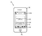
図5は、ソフトウェア・アプリケーション/ツール54のログイン画面60の概略的な表現である。これは、ユーザーがソフトウェア・アプリケーション/ツール54を立ち上げるときにいつも表示されるものである。ユーザーがすでにアカウントを確立していれば、ユーザーは、電子メール・アドレスおよびパスワードを含む自分の確立されたアカウント情報をボックス62および64に入力し、ログイン・ボタン66を選択することによって、ソフトウェア・アプリケーション/ツール54にログインできる。しかしながら、ユーザーが確立されたアカウントのない、ソフトウェア・アプリケーション/ツール54の新規ユーザーである場合には、ユーザーは「新規アカウントを作成」リンク68を選択してもよい。「新規アカウントを作成」リンク68の選択に応答して、ソフトウェア・アプリケーション/ツール54は、図6に示される新規アカウント作成画面70を表示させる。新規アカウントを作成するために、ユーザーは新規アカウント作成画面70にある種の情報を入力しなければならない。具体的には、ユーザーは、ボックス72および74に自分の名前を、ボックス76に自分の電子メール・アドレスを入力しなければならない。本例示的実施形態では、入力される電子メール・アドレスはシステム2にとって一意的でなければならず、ユーザーの「ユーザー名」として使用される。ユーザーは、「装置番号」をボックス78に入力することも求められる。「装置番号」は、システム2においてユーザーが使用している圧力支援システム4の圧力発生コンポーネントのシリアル番号である。「装置番号」はユーザーによって手動で入力されてもよい(すなわち、タッチスクリーン・ディスプレイ42を使ってタイプされてもよい)し、あるいは圧力支援システム4上で与えられるバーコードおよびポータブル電子装置8にロードされたもしくはソフトウェア・アプリケーション/ツール54の一部として提供されている好適なバーコード・スキャン/読み取りアプリケーションを使ってスキャンされてもよい。図示した例示的な実施形態では、そのようなバーコード・スキャン/読み取りアプリケーションは、図6に示されるスキャン・ボタン79を選択することによってトリガーされる。「装置番号」を取得/入力する他の方法も考えられる。たとえば、限定するものではないが、ポータブル電子装置8前記シリアル番号の画像を捕捉し、(たとえばポータブル電子装置8にロードされたまたはソフトウェア・アプリケーション/ツール54の一部として提供されているアプリケーションにおいて)光学式文字認識を使って「装置番号」を抽出する、あるいはローカル・エリアをブルートゥース(登録商標)またはWi-Fiスキャンして「装置番号」をロードするなど。本例示的実施形態では、入力された「装置番号」は、システム2において一意的である必要はない。むしろ、「リサイクルされた」装置のためのものであってもよい。つまり、その番号は前に第一の、以前の電子メール・アドレス(ユーザー名)とともに使用されたものであり、今は別の、現在の電子メール・アドレス(ユーザー名)とともに使用される。だが、本例示的実施形態では、システム2は、入力された「装置番号」がシステム2によって有効である、つまり既知のモデル圧力支援システム4の所定の範囲内にはいるものとして認識されることは要求する。ユーザーはまた、図6に示されるボックス80および82に、自分のアカウントと一緒に使用されるべきパスワードを入力し、確認することも求められる。こうして、ユーザーが今述べた情報(電子メール・アドレスおよび「装置番号」を含む)を入力する(そして提出ボタン84を選択する)ことによってアカウントを作成しようとするとき、中央コンピュータ・システム6は、その電子メール・アドレスが一意的であるかどうかおよび「装置番号」が有効であるかどうかをチェックし、その電子メール・アドレスが一意的でありかつ「装置番号」が有効であると判定される場合にのみ、アカウントの作成を許諾する。これらのチェックのいずれかが失敗した場合には、ユーザーは、その問題を通知されてもよく、ソフトウェア・アプリケーション/ツール54のヘルプ部分にまたはヘルプ・ウェブサイトにリダイレクトされてもよい。
FIG. 5 is a schematic representation of the
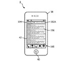
ユーザーによるソフトウェア・アプリケーション/ツール54の最初の使用の間、今述べたようにして新規アカウントを作成したのち、第一の使用画面86が図7に見られるようにタッチスクリーン・ディスプレイ42上に表示される。図7に示されるように、ユーザーはこれが圧力支援システム4を使う最初であるかどうか(すなわち、これがユーザーの最初の療法セッションであるかどうか)を尋ねられる。ユーザーがボタン88を選択することによって「Yes」〔はい〕を示す場合、ソフトウェア・アプリケーション/ツール54はその「最初の夜の案内」部分に進む。これについてはのちに詳述する。ユーザーがボタン90を選択することによって「No」〔いいえ〕を示す場合でも、ユーザーは、ボタン92または94を選択することによって「最初の夜の案内」部分に進む機会を与えられる。
During the initial use of the software application /
ソフトウェア・アプリケーション/ツール54の「最初の夜の案内」部分は、ユーザーに、自分の特定の睡眠呼吸障害状態(たとえばOSA)に関し、またユーザーがPAP療法を提供するために使う圧力支援システム4の詳細に関し教育を提供するよう設計される。「最初の夜の案内」部分の第一のセクションでは、最初の夜のビデオ画面96が図8に見られるようにタッチスクリーン・ディスプレイ42上で提供される。最初の夜のビデオ画面96は、ユーザーの睡眠呼吸障害状態およびそのための治療に関係するいくつかのビデオへのリンクを提供する。それらは関連するアイコン98を選択することによってユーザーによってアクセスされうる。本例示的実施形態では、各アイコン98は、そのビデオがアクセスされうるサイト(限定するものではないがユーチューブ(登録商標)のようなサードパーティーのコンテンツ共有サイトまたはソフトウェア・アプリケーション/ツール54もしくは圧力発生システム4の提供者によってもしくはヘルスケア提供者または耐久医療設備(DME: durable medical equipment)供給者によって維持されているサイト)へのリンクである。理解されるであろうが、該リンクを介してアクセスされる実際のビデオは、動的に更新/変更されてもよい(すなわち、コンテンツが動的に更新されてもよい)。また、本例示的実施形態では、ソフトウェア・アプリケーション/ツール54がバナー100を介して、「最初の夜の案内」部分の次のセクションに進むために、ユーザーが少なくとも一つのビデオを再生することを推奨する。スキップ・ボタン102の選択によって、ユーザーはこの第一のセクションをスキップできる。進行バー104が最初の夜のビデオ画面96上に表示され、ユーザーに対して、「最初の夜の案内」部分において残っているステップ数を示す。さらに、図8において見られるように、ひとたびビデオが閲覧されたら、「チェック」アイコンがその完了を示す。また、ひとたびビデオが閲覧されたら、ユーザーが「最初の夜の案内」部分の次のセクションに進めるようにするために、次ボタン106が提供される。
The “First Night Guidance” portion of the software application /
「最初の夜の案内」部分の、「マスク案内」セクションと呼ばれる第二のセクションでは、ユーザーはソフトウェア・アプリケーション/ツール54に対して、圧力支援システム4において使っている呼吸マスクまたは患者インターフェース20(図2)の型を示し、その情報に基づいて、ソフトウェア・アプリケーション/ツール54は、特定の呼吸マスクまたは患者インターフェース20に関して情報をユーザーに提供する。このプロセスは図9に示されている。図9は、タッチスクリーン・ディスプレイ42上で提供されるいくつかの例示的なマスク案内画面108を通じた進行を示している。図9に示されるように、第一のマスク案内画面108Aは、ユーザーがそこから選択するための種々のマスク型(たとえば、鼻、枕、フルフェース)の一覧110を提供する。バナー112がユーザーに、一覧110から自分のマスク型を選択するよう指示する。ひとたび一覧110からのマスク型が選択されたら、第二のマスク案内画面108Bが、ユーザーがそこから選択するための(たとえばブランド名または製造/モデル番号による)個別的なマスク・モデルの一覧114を提供する。バナー116がユーザーに、一覧114から自分のマスク・モデルを選択するよう指示する。ひとたび一覧114からのマスク・モデルが選択されたら、第三のマスク案内画面108Cが、選択されたマスク・モデルの画像118を提供する。第三のマスク案内画面108Cには、正しければユーザーがマスク・モデルを設定できるようにするためにボタン120が設けられている。ボタン120の選択(すなわち、特定のマスク・モデルの設定)に応答して、設定されたマスク・モデルに基づいて選択され、それに対応するマスク案内122を含む第四のマスク案内画面108Dが提供される(すなわち、ひとたびマスク・モデルが設定されたら、ソフトウェア・アプリケーション/ツール54において適切なマスク案内122にアクセスする呼び出しが行なわれる)。マスク案内122は、設定されたマスク・モデルおよびその使用に関係する情報を提供する。マスク案内122は、限定するものではないが、テキスト、写真、図面、ステップごとの指示および/またはビデオを含みうる。第四のマスク案内画面108Dは、選択されるとユーザーが「最初の夜の案内」部分の次のセクションに進めるようにする完了ボタン124をも含んでいる。
In the second section of the “First Night Guidance” section, called the “Mask Guidance” section, the user is directed to the software application /
上記の図示した実施形態では、マスク型およびモデルが手動のユーザー入力を使って指定される。代替的な実施形態では、マスク型およびモデルは、多数の異なる技術を使って自動的に発見/認識されてもよい。たとえば、限定するものではないが、マスクまたは患者インターフェース20上で与えられるバーコードをポータブル電子装置8を使って読み取る、あるいはマスクまたは患者インターフェース20のデジタル画像をポータブル電子装置8を使って(すなわちそこに設けられているデジタル・カメラを用いて)捕捉し、ポータブル電子装置8上で提供される認識ソフトウェアを使って捕捉された画像からマスク型およびモデルを特定するなどである。さらに、圧力支援システム4の他のコンポーネント(たとえば、ガス送達ホース、加湿器、一つまたは複数のフィルタなど)が、今述べた手動入力および/または自動発見/認識によって、ソフトウェア・アプリケーション/ツール54に対して同定されてもよい。コンポーネント同定の他の具体的な方法も可能である。たとえば、限定するものではないが、梱包材料の写真(画像)、ガス送達ホースの写真(画像)、QRバーコード、ホース/マスク上のテキスト認識を使うこと、ブルートゥース(登録商標)または他の無線対応マスクを探すことおよびコンポーネント(たとえばマスク)を圧力発生装置(たとえばCPAP)に当該コンポーネントの知識をすでに有しているかどうかを問い合わせることを通じて識別することなどである。
In the illustrated embodiment above, the mask type and model are specified using manual user input. In alternative embodiments, mask types and models may be automatically discovered / recognized using a number of different techniques. For example, without limitation, a barcode provided on the mask or
「装置案内」セクションと呼ばれる、「最初の夜の案内」部分の第三のセクションでは、ソフトウェア・アプリケーション/ツール54は、圧力支援システム4の特定の圧力発生装置(図2の点線内の諸コンポーネント)の動作および使用に関して、単数または複数の装置案内画面126においてユーザーに情報を提供する。図10に見られるように、装置案内画面(単数または複数)126は、ユーザーのアカウントの作成の間にユーザーによって与えられた「装置番号」情報に基づいて選択される装置案内128を含む。装置案内128は、限定するものではないが、テキスト、写真、図面、ステップごとの指示および/またはビデオを含みうる。装置案内画面(単数または複数)126は、選択されるとユーザーがソフトウェア・アプリケーション/ツール54の次の部分に進めるようにする完了ボタン130をも含んでいる。これは、後述するように、「睡眠」画面とも称される、ソフトウェア・アプリケーション/ツール54についての「ホーム」画面である。
In the third section of the “First Night Guidance” section, referred to as the “Device Guidance” section, the software application /
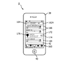
図11は、図示した例示的実施形態におけるソフトウェア・アプリケーション/ツール54の睡眠画面130Aを示している。初めてのユーザーについては、図11に示されるような睡眠画面130Aが、「最初の夜の案内」部分の完了後に表示される。ユーザーが、本例示的実施形態において、圧力支援装置4からの生データが、本稿の他所で記述されるように患者/療法メトリックに処理されることができるようどのようにして中央コンピュータ・システム6に定期的に提供されるかを決定できるのは、この時点においてである。特に、図11に見られるように、この段階での睡眠画面130Aは、ユーザーに対して、自分の圧力支援装置4のためのデータ接続方法が確立されなければならないことを示すメッセージ132と、ユーザーが種々のデータ接続方法についてもっと知りたい場合にユーザーによって選択されうるメッセージ134とを含む。データ接続方法を選択するためには、ユーザーはメッセージ132を選択する(「タップする」)必要がある。ユーザーがそうすると、図12に示されるデータ接続画面136Aがタッチスクリーン・ディスプレイ42上で提供される。次ボタン138を選択することによって、ユーザーは図12に示されるデータ接続画面136Bに進むことができる。データ接続画面136Bは、この限定しない例示的実施形態の異なるデータ接続方法のそれぞれについて一つで、三つのボタン/メッセージ140A、140B、140Cを含む。
FIG. 11 illustrates the
より特定的には、ボタン/メッセージ140Aは、圧力支援装置4とポータブル電子装置8との間の短距離無線通信(図示した実施形態ではブルートゥース(登録商標))が用いられるデータ接続のためである。ボタン/メッセージ140Aが選択されたら、図12に示されるセットアップ画面142が表示される。この画面は、そのデータ接続方法についての情報と、ユーザーがそのデータ接続方法をシステム2のための確立された方法として選択しうるボタン144とを含む。ボタン/メッセージ140Bは、圧力支援装置4とPC 10との間のポータブル・メモリ・デバイス(図示した実施形態ではSDカード)を使ったデータの転送が用いられるデータ接続のためである。ボタン/メッセージ140Bが選択されたら、図12に示されるセットアップ画面146が表示される。この画面は、そのデータ接続方法についての情報と、ユーザーがそのデータ接続方法をシステム2のための確立された方法として選択しうるボタン148とを含む。ボタン/メッセージ140Cは、圧力支援装置4から中央コンピュータ・システム6へのモデムを使ったデータの転送が用いられるデータ接続のためである。ボタン/メッセージ140Cが選択されたら、図12に示されるセットアップ画面150が表示される。この画面は、そのデータ接続方法についての情報と、ユーザーがそのデータ接続方法をシステム2のための確立された方法として選択しうるボタン152とを含む。
More specifically, the button / message 140A is for a data connection using short-range wireless communication (Bluetooth® in the illustrated embodiment) between the pressure assist
データ接続画面136Bは、Wi-Fiまたは他の無線接続オプションのような他のデータ接続方法のためのオプション(すなわち、他のボタン/メッセージ)をも含んでいてもよい。さらに、ソフトウェア・アプリケーション/ツール54は、圧力支援システム4またはシステム2の他の部分の詳細を与えられて、そのユーザーにとっての「最良」の接続方法を提案するよう適応/構成されていてもよい。たとえば、ユーザーによって選択されたときに、圧力支援システム4またはシステム2の他の部分の詳細を与えられたときのそのユーザーにとっての「最良」の接続方法がディスプレイ42上でユーザーに対して提案されるようなメッセージ/ボタンが、データ接続画面136B上で提供されてもよい。ある実施形態では、提案される「最良」の接続方法は、(本稿で記述されるようにして)前に同定された圧力支援システム4およびポータブル電子装置8の既知の機能に基づいていてもよい。たとえば、圧力支援システム4の「装置番号」(たとえばシリアル番号)が、その圧力支援システム4がブルートゥース(登録商標)またはWi-Fi機能をもち、ポータブル電子装置8もブルートゥース(登録商標)またはWi-Fi機能をもつことを示す場合、ソフトウェア・アプリケーション/ツール54は、ブルートゥース(登録商標)またはWi-Fiを通じて圧力支援システム4を発見し、それを確立されたデータ接続方法として選択することを提案する。圧力支援システム4の「装置番号」(たとえばシリアル番号)が、その圧力支援システム4がブルートゥース(登録商標)/Wi-Fi/等をサポートしないことを示す場合、ソフトウェア・アプリケーション/ツール54は、SDカード・オプションを「最良」の接続オプションとして提案する。もう一つの例として、「最良」の接続方法を提案するための上記メッセージ/ボタンの選択に応答して、ポータブル電子装置8が、ブルートゥース(登録商標)、Wi-Fiまたは他の何らかの無線ネットワーク上で利用可能な近くの圧力発生装置(たとえば圧力支援システム4の一部)があるかどうかを見るために無線で探索させられる。もしあれば、ソフトウェア・アプリケーション/ツール54は、それを確立されたデータ接続方法として選択することを提案する。
ひとたび今述べたようにしてデータ接続方法が選択されたら、ソフトウェア・アプリケーション/ツール54は図13に示されるような睡眠画面130Bを表示する。さらに、睡眠画面130Bは、最初の使用後(すなわち、上記の初期セットアップ後)、ユーザーがソフトウェア・アプリケーション/ツール54を立ち上げ、自分のアカウントにログインするたびに表示される画面である。よって、最初の使用後(すなわち、初期セットアップ後)は、睡眠画面130Bはソフトウェア・アプリケーション/ツール54のためのホーム画面として機能する。図13に見られるように、睡眠画面130Bは二つの主たる領域であるメトリック領域154および動的メッセージング領域156を含む。
Once the data connection method has been selected as just described, the software application /
メトリック領域154では、睡眠画面130Bは、本例示的実施形態では中央コンピュータ・システム6によって生成されるある種の患者/療法メトリックに関する情報を表示する。図示した例示的実施形態では、次の三つの患者/療法メトリックが用いられ、それに関係する情報がメトリック領域154に表示される:(i)マスク・フィット・メトリック、これは圧力支援システム4によって検出されるマスク漏れの量に基づいて決定されるフィット割合である、(ii)療法メトリック、これは、睡眠期間中(たとえば夜間)ユーザーによる圧力支援装置4の使用の長さを時間単位で示すもので、圧力支援システム4によって検出される使用データに基づいて決定される、(iii)AHIメトリック、これは圧力支援システム4によって測定されるデータに基づいて決定される睡眠期間(たとえば夜間)についての無呼吸/呼吸低下インデックス(apnea/hypopnea index)である。当技術分野で知られているように、無呼吸/呼吸低下インデックスは、(無呼吸または呼吸低下)イベント数を、睡眠時間数で割ることによって計算される。上記の三つのメトリックは単に例示的であることが意図されており、本発明の範囲内で、上記のものの代わりのおよび/または上記のものに加えた他の、異なる患者/療法メトリックが用いられてもよいことは理解されるであろう。睡眠画面130Bにおいて、最も最近の睡眠期間(たとえば前夜)についてのメトリック値がメトリック領域154に表示される。
In the
さらに、ユーザーは、グラフィック・アイコンを含む、メトリックの下のボタン領域155を選択する(たとえば押して保持する)ことによって、個々のメトリックの任意のものについての履歴にアクセスしうる。これは、睡眠画面130Cを示す図14において療法メトリックについて例証されている。図14に見られるように、図示した実施形態では、八つの期間(たとえば八日)以上のデータが利用可能である場合には、十四の期間(たとえば十四日)の使用についての療法メトリックがグラフィックな形で示される。八つの期間(たとえば八日)未満のデータが利用可能である場合には、データが利用可能な使用期間(たとえば七つの期間(たとえば七日)の使用)についての療法メトリックがグラフィックな形で示される。メトリックについての目標線158(これはそのメトリックについてのあらかじめ決定された目標値を表わす)が、ユーザーがすぐ参照できるよう設けられている。本例示的実施形態では、療法メトリックについての目標は次のように駆動される。最初の七つの期間/日、目標=2時間;その後の七日毎、目標=1.2×(前の七つの期間/日の全使用)/7時間。同様の履歴データおよび目標がマスク・フィットおよびAHIメトリックについて表示されてもよい。
In addition, the user can access the history for any of the individual metrics by selecting (eg, pressing and holding) the
図13および図14において見られるように、動的なメッセージング領域156は、動的メッセージ158のスケーラブルな一覧を含む。図示した実施形態では、各動的メッセージ158は二行のテキストを含み、ソフトウェア・アプリケーション/ツール54の別の部分をトリガーするおよび/またはサードパーティー・ビデオ・コンテンツのような追加的なコンテンツへのアクセスを提供するリンクを含んでいてもよい。
As seen in FIGS. 13 and 14, the
たとえば、動的メッセージ158は、患者/療法メトリックの一つまたは複数に基づいて圧力支援システム4の使用に関する問題または論点を示してもよく、問題についての情報および/または解決策へのリンクを提供してもよい。たとえば、マスク・フィット・メトリックがある閾値レベルより低いと判定される場合(たとえば<75%)、動的メッセージ158はユーザーにその問題を通知し(「マスク・フィットがよくないと思われます」)、どのように漏れ問題に対処するかについての指示、ビデオまたは関連するオンラインの議論のフォーラム(たとえば選択された掲示板)へのリンクおよび/または他の情報を提供するソフトウェア・アプリケーション/ツール54のトラブルシューティング・セクション/案内(本稿の他所で記載)をトリガーするリンクを提供してもよい。あるいはまた、療法メトリックがある閾値レベルより低いと判定される場合(たとえば<2時間)、それは、ユーザーがマスク・フィットおよび/または快適さ(たとえば、圧力点、赤い印、マスク不安定、チューブ問題)および/または療法快適さ(呼気の困難、入眠の困難、乾いたまたは濡れた鼻、鼻づまり、ガスによる膨満感、頻繁な覚醒)に関する問題を有していることを示している可能性がある。応答して、ユーザーにその問題を通知し(「あなたの使用が低すぎるようです。これは……のためである可能性があります。」)、どのように使用問題に対処するかについての指示、ビデオまたは関連するオンラインの議論のフォーラム(たとえば選択された掲示板)へのリンクおよび/または他の情報を提供するソフトウェア・アプリケーション/ツール54のトラブルシューティング・セクション/案内をトリガーするリンクを提供する動的メッセージ158が提供されてもよい。本例示的実施形態のある側面によれば、トラブルシューティングは、本稿の他所で記述されたように設定/指定された圧力支援システム4の特定の設備に基づいてカスタマイズされる(たとえば、トラブルシューティング・セクション/案内が、前に設定されたマスク型およびモデル番号に特有なものである)。たとえば、ユーザーは、ユーザーの設備に固有のオンライン議論フォーラム(たとえば掲示板)へのリンクを与えられてもよい。
For example, the
もう一つの例では、動的メッセージ158は、患者/療法メトリックについての新たな目標が設定されたこと(新たな目標はリストされてもよいし、あるいは新たな目標へのリンクが提供されてもよい)または患者/療法メトリックについてのカスタマイズされた目標(本稿の他所で記載)が達成されたことを示してもよい。
In another example, the
さらにもう一つの例では、動的メッセージ158は、圧力支援システム4のコンポーネント(たとえば、マスクまたは患者インターフェース20または送達導路18または加湿器もしくはフィルタのようなアクセサリー)がクリーニングされる、サービスを受けるおよび/または交換される必要があるという通知を提供してもよい。そのような通知は、単に時間(たとえば月)の経過に基づいていてもよいし、または総合的な実際の使用パラメータ(たとえばある時間数の実際の使用)に基づいていてもよく、ユーザーまたはDME供給者によってカスタム設定されてもよく、またはソフトウェア・アプリケーション/ツール54におけるデフォルト設定であってもよい。さらに、そのような通知は、注文オプションへのリンクを提供してもよい(たとえば、通知を押すのを選択すると、ユーザーがDME固有の注文ウェブサイトにプッシュされるまたは自動的な(電子的)注文が所定のDME供給業者にプッシュされる)。
In yet another example, the
さらにもう一つの例では、動的メッセージ158は、一つまたは複数のビデオを見るまたはソフトウェア・アプリケーション/ツール54の装置案内および/またはマスク案内部分にアクセスしてそれを使うことの推薦を含んでいてもよい(これらも、本稿の他所で記載されるように設定/指定された圧力支援システム4の特定の設備についてカスタマイズされる)。そのような動的メッセージ158の内容は、内容(その特定のビデオ・コンテンツまたはその特定の装置案内および/またはマスク案内の内容)が古びないよう、時間とともに、ソフトウェア・アプリケーション/ツール54の提供者によってまたはDME供給者によって更新されてもよく、関連するDME供給者ごとにカスタマイズされることができる。また、動的メッセージ158は、圧力発生システム4において使うコンポーネントについて広告するために使われてもよい(たとえば、最新のマスク・デザイン……「発売中の最新のフルフェース・マスクをお見せします」)。
In yet another example, the
さらにもう一つの例では、動的メッセージ158は、本例示的実施形態では中央コンピュータ・システム6によって生成される患者/療法メトリック(たとえばモニタリングされるAHI)について、あるいは患者の可能な生理的状態に対応する圧力支援システム4からの他の任意のモニタリングされるパラメータについて、ある種の提案を含んでいてもよい。たとえば、患者が、最近チェーン・ストークス呼吸(CSR: Cheyne-Stokes respiration)にある夜のずっと高い割合を示しているまたはより高いAHIまたは他の任意のモニタリングされるパラメータを有する場合、ソフトウェア・アプリケーション/ツール54は、患者に医師またはDME供給者に接触することを促すおよび/または患者を質問票(息切れしますか?歩いている間に呼吸に困難を感じますか?)にプッシュする動的メッセージ158を生成するよう構成されていてもよい。該質問票は次いで、モニタリングされるパラメータ(単数または複数)および質問票が医学的状態(たとえば喘息、肺水腫など)の悪化の可能性が高いことを示唆する場合には、医師に連絡することに導く。
In yet another example, the
さらに、さらに、図11、図13および図14に見られるように、中でも、タッチスクリーン・ディスプレイ42の下部にナビゲーション・セクション160が設けられる。ナビゲーション・セクション160はいくつかのタブ(図示した実施形態では「睡眠」、「目標」、「学習」、「コーチ」および「ケア」とラベル付けされている)を含む。各タブは、ソフトウェア・アプリケーション/ツール54の主要な部分に対応する。それらのタブの選択により、ユーザーはソフトウェア・アプリケーション/ツール54のそれらの部分に選択的にナビゲートできる。こうして、「睡眠」タブの選択は、ユーザーを睡眠画面130B(図13)に連れて行く。
Further, as can be seen in FIGS. 11, 13 and 14, a
あるさらなる側面によれば、ソフトウェア・アプリケーション/ツール54は「目標」部分も含む。ここでは、ユーザーは患者/療法メトリックに基づいて目標を設定し、それらの目標に向けた進行を追跡することができる。ユーザーは、ナビゲーション・セクション160の「目標」タブを選択することによって、「目標」部分にアクセスしうる。図15に示される目標画面162Aは、「目標」タブが選択されるときにタッチスクリーン・ディスプレイ42上に表示される。目標画面162Aは、下記で述べる「目標」部分のさまざまなセクションの間でのナビゲーションを可能にするタブを有するナビゲーション・セクション164を含む。
According to certain further aspects, the software application /
「私の目標」セクションでは、いくつかの目標セクション166が表示される。各目標セクション166は、患者/療法メトリックに基づく特定の目標に対応し、各目標セクションは、それらの目標に向けた進行を追跡する進行バー168を含む。本例示的実施形態では、四つのあらかじめ決定された目標カテゴリーが利用され(図15に示される)、ユーザーは各カテゴリーについて目標値をカスタム設定することができる。それらの目標カテゴリーは:(i)月における圧力支援システム4の4+時間の使用がある日数、(ii)圧力支援システム4の連続使用日数、(iii)圧力支援システム4の4+時間の使用がある連続日数、および(iv)>75%のマスク・フィットでの圧力支援システム4の連続使用日数。他の目標カテゴリーも可能であることは理解されるであろう。本例示的実施形態では、各目標セクション166における各進行バー168は、中央コンピューティング・システム6から受領されるメトリック・データに基づいて定期的に(たとえば毎日)更新される。本例示的実施形態では、ユーザーは、図16に示されるように目標設定画面170を使って各目標セクション166についての目標値を設定および変更することができる。各目標設定画面170は、対応する目標セクション166を選択することによってアクセスされてもよく、「−」および「+」ボタン171および173はそれぞれ、目標値を調整するために使用されうる。あるいはまた、ソフトウェア・アプリケーション/ツール54は、圧力支援システム4によって測定されたデータおよび/または以前の患者/療法メトリック値に基づいて自動的に目標を設定するよう構成されていてもよい。
In the “My Goals” section,
図17を参照するに、目標セクション166における目標が達成されると、目標画面162Aに、完了ボタン174および達成アイコン(たとえばカップ)176を含むメッセージ172が提供される。本例示的実施形態では、ユーザーが目標画面162A上で与えられる完了ボタン174を選択する(押す)場合、達成アイコン176が図18に示されるようなナビゲーション・セクション164の達成タブにアニメーションで移行する。ユーザーがナビゲーション・セクション164の達成タブを選択すると、達成された目標全部のリスト178が図19に示される目標画面162B上で与えられる。図19において見られるように、各達成された目標は、関連付けられた達成目標セクション180において与えられる。このセクションが本例示的実施形態では達成された目標を記述する。図19に示されるように、いずれかの特定の達成目標セクション180を選択すると、二つの行動アイコン、つまりメール・アイコン184およびごみ箱アイコン186を含むメニュー182がアクティブ化される。図20に示されるように、メール・アイコン184を選択すると、ポータブル電子装置8の電子メール・アプリケーションがアクティブ化され、あらかじめ選択された単数または複数の受信者に当てられた電子メール・メッセージ188がメッセージにあらかじめ入れられている状態になり、ユーザーが特定の目標を達成したことを示す。このように、ユーザーは、そのような達成の知らせを受け取る一または複数の個人(たとえば、親または子のような家族または友人)を指定することができ、それにより、知らせを受ける人は圧力支援システム4の実際の使用およびユーザーが受ける療法について最新情報を伝えられることができる。代替的な実施形態では、限定するものではないがツイッター(登録商標)およびフェイスブック(登録商標)のようなソーシャル・メディア・アウトレット/サイト上でユーザーが特定の目標を達成したことを示すメッセージ(たとえば図21に示されるメッセージ190)を自動的に生成し、ポストするための、あるいはショート・メッセージ・サービスのメッセージ(SMS)またはマルチメディア・メッセージング・サービス(MMS)のような代替的な電子メッセージング・サービスを使ってメッセージを自動的に生成し、(一または複数のあらかじめ決定された個人に)送るための追加的なアイコンが設けられることができる。ごみ箱アイコン186を選択すると、関連付けられた達成目標セクション180は削除される。
Referring to FIG. 17, when the goal in
今述べた目標の達成に加えて、限定するものではないが本稿で記載される患者/療法メトリックのような他の療法情報が、ポータブル電子装置8によって、自動的かつ定期的に一または複数の個人(たとえば、患者、ホームケア提供者および医師以外の第三者)におよび/またはソーシャル・メディア・アウトレット/サイトに電子メールで送られてもよい。
In addition to achieving the goals just described, other therapy information, such as but not limited to the patient / therapy metric described herein, may be automatically and periodically transmitted by the portable
あるさらなる側面によれば、ソフトウェア・アプリケーション/ツール54は「学習」部分をも含む。ここでは、ユーザーは、自分の睡眠呼吸障害の状態および/またはその状態を治療するために使っている圧力支援システム4についての情報を得ることができる。ユーザーは、ナビゲーション・セクション160の「学習」タブを選択することによって、「学習」部分にアクセスしうる。図22に示される学習画面192Aは、「学習」タブが選択されるときにタッチスクリーン・ディスプレイ42上に表示される。学習画面192Aは、下記で述べる「学習」部分のさまざまなセクションの間でのナビゲーションを可能にするタブ(「無呼吸」「設備」「トラブルシューティング」)を有するナビゲーション・セクション194を含む。
According to certain further aspects, the software application /
「無呼吸」タブが選択されると、図22に示されるようなリスト196が提供される。このリストは、ユーザーの睡眠呼吸障害の状態(たとえばOSA)に関係する教育用のビデオおよび/または文書へのいくつかのリンクを含む。同様に、「設備」タブが選択されると、(学習画面192B上の)図23に示されるようなリスト198が提供される。このリストは、ユーザーによって使用されている圧力支援システム4の個別的なコンポーネントに関する教育用のビデオおよび/または文書へのいくつかのリンクを含む。さらに、図23に見られるように、リスト198は、本稿の他所で記載されるソフトウェア・アプリケーション/ツール54の「装置案内」および「マスク案内」セクションへのリンクをも含む。ここでもまた、「装置案内」および「マスク案内」セクションは、本稿の他所で記述されるようにユーザーによって設定されたところの、ユーザーによって使用されている圧力支援システム4のコンポーネントに固有である。「トラブルシューティング」タブが選択されると、ユーザーはソフトウェア・アプリケーション/ツール54によって、圧力支援システム4を使う療法の間にユーザーが経験していることがありうるさまざまな問題に対処するための階層状のオプションを通じて案内される。最終的には、ビデオ・リンクまたは文書で終わる。本例示的実施形態では、対処されうる(そして提案される解決策が与えられる)問題は、マスク漏れ、マスク不快さ、睡眠中のマスクの外れ、マスク不安定、ユーザーの顔面上の圧力点/印、呼気の困難、入眠の困難、不十分な療法圧力、動きの制約および重い感覚などのチューブの問題ならびに乾いたまたは濡れた鼻、鼻づまり、ガスによる膨満感および/または頻繁な覚醒といった副作用を含む。本例示的実施形態のある側面によれば、トラブルシューティングは、本稿の他所で記述されるように設定/指定された圧力支援システム4の特定の設備に基づいてカスタマイズされる(たとえば、トラブルシューティングは、事前に設定されたマスク型およびモデル番号ならびに圧力支援システム4の圧力発生装置のモデルに固有なものとなる)。
When the “Apnea” tab is selected, a
本例示的実施形態のさらにもう一つの側面では、ソフトウェア・アプリケーション/ツール54は「コーチ」部分も含む。ここでは、ユーザーによるよりよい療法遵守を促すために、動機付け強化療法(MET: Motivational Enhancement Therapy)が用いられる。ユーザーは、ナビゲーション・セクション160の「コーチ」タブを選択することによって、「コーチ」部分にアクセスしうる。「コーチ」部分は、患者に圧力支援療法を使う動機について患者固有の質問をし、ひとたび患者が治療を始めたら、患者自身の答えを送達することによって、遵守を高めることをねらいとした独自技術である。「コーチ」部分は、あらかじめ決定された「仮想介入(virtual interventions)」において特定のプロトコルを通じて患者を案内する。本例示的実施形態では、仮想介入が行なわれるのは、療法メトリックに基づいて、前の関連する期間の間に患者が圧力支援システム4を使ったのがある時間(たとえば2時間)未満であると判別されたときである。また、本例示的実施形態では、次の三つのMET技法が組み込まれる。(i)動機、ここでは、仮想介入点(たとえば初めて患者の使用が低くなったとき)において、睡眠療法を使う患者の動機が1〜10のスケール上でレート付けされ、次いで患者がそのレート付け、特に療法を使うことについての主たる動機について質問される、(ii)心臓リスク、ここでは、別の仮想介入点(たとえば二回目に患者の使用が低くなるとき)において、その患者は、諸患者の死亡率を比較する研究を使って教育され、次いで患者はその研究のデータからどのように影響されたかを質問される、(iii)気持ち、ここでは、別の仮想介入点(たとえば三回目に患者の使用が低くなるとき)において、患者は無呼吸イベントを経験している実際の患者のビデオ・クリップを見せられ、次いで患者はビデオを見てどのような気持ちになったかについて質問される。その後、ソフトウェア・アプリケーション/ツール54のある側面によれば、療法メトリックに基づいて、前の関連する期間の間にその患者が圧力支援システム4を使ったのがある時間(たとえば2時間)未満であると判別されたとき、患者は(i)(自分が入力した)療法を使う主たる動機、(ii)(自分が入力した)上記研究のデータからどのように影響されたかについての自分の陳述および(iii)実際の無呼吸を患う患者のビデオを見てどう感じたかについての自分の陳述のうちの一つまたは複数のリマインダー/通知を与えられてもよい。
In yet another aspect of the exemplary embodiment, the software application /
本例示的実施形態のさらにもう一つの側面では、ソフトウェア・アプリケーション/ツール54は「ケア」部分をも含む。ここでは、患者のホームケア提供者が、患者が該提供者に連絡できる機構(たとえば該提供者のロゴを印したもの)を提供することを選んでもよい。ユーザーは、ナビゲーション・セクション160の「ケア」タブを選択することによって、「ケア」部分にアクセスしうる。図示した実施形態では、ユーザーがナビゲーション・セクション160の「ケア」タブを選択すると、図24に示されるケア画面200がタッチスクリーン・ディスプレイ42上に与えられる。ケア画面200は、呼び出し(call)ボタン202および電子メール・ボタン204を含む。呼び出しボタン202を選択すると、ポータブル電子装置8の電話アプリケーションがアクティブ化され、ユーザーのホームケア提供者に電話がかけられる。電子メール・ボタン204を選択すると、ポータブル電子装置8の電子メール・アプリケーションがアクティブ化され、ホームケア提供者の電子メール・アドレスへの電子メールが生成される。該電子メールは、質問などを含めるようユーザーが書き込むことのできる部分をもつ。
In yet another aspect of the exemplary embodiment, the software application /
このように、本稿で詳細に述べたように、システム2は、呼吸療法装置の使用を必要とする状態(たとえばOSA、CSA、CSR、COPのような睡眠呼吸障害の状態または家庭換気療法を必要とする状態)を患っている患者が自分の状態および治療を管理するための、任意の、使いやすい、ソフトウェア・ベースの機構を、患者の状態および患者の固有の療法に関するカスタマイズ/パーソナル化された教育およびフィードバックを提供することによって、提供する。ここで、該機構の使用は、療法遵守を高め、よって治療を改善する可能性が高い。
Thus, as detailed in this paper,
請求項において、括弧に入れた参照符号があったとしても、その請求項を限定するものと解釈してはならない。「有する」または「含む」の語は、請求項に挙げられている以外の要素や段階の存在を排除しない。いくつかの手段を列挙している装置請求項において、それらの手段のいくつかは、同一のハードウェア品目によって具現されてもよい。要素の単数形の表現はそのような要素の複数の存在を排除しない。いくつかの手段を列挙するいかなる装置請求項においても、それらの手段のいくつかは、同一のハードウェア品目によって具現されてもよい。ある種の要素が互いに異なる従属請求項に記載されているというだけの事実が、それらの要素が組み合わせて使用できないことを示すものではない。 In the claims, any reference signs placed between parentheses shall not be construed as limiting the claim. The word “comprising” or “including” does not exclude the presence of elements or steps other than those listed in a claim. In the device claim enumerating several means, several of these means may be embodied by one and the same item of hardware. The singular representation of an element does not exclude the presence of a plurality of such elements. In any device claim enumerating several means, several of those means may be embodied by one and the same item of hardware. The mere fact that certain elements are recited in mutually different dependent claims does not indicate that they cannot be used in combination.
本発明について、例解のために、現在のところ最も実際的で好ましい実施形態であると考えられるものに基づいて詳細に説明してきたが、そのような詳細はあくまでもその目的のためであって、本発明は開示される実施形態に限定されるものではなく、逆に、付属の請求項の精神および範囲内にある修正および等価な構成をカバーすることが意図されていることは理解しておくものとする。たとえば、本発明が、可能な限りにおいて、任意の実施形態の一つまた複数の事項が他の任意の実施形態の一つまたは複数の事項と組み合わされることができることを考えている。
いくつかの態様を記載しておく。
〔態様1〕
患者に情報を提供する方法であって、患者は、呼吸ガスの流れを患者に送達することによって患者の状態を処置するよう患者に療法を提供するよう構成された圧力支援システムを使い、当該方法は:
コンピューティング装置において、前記圧力支援システムの一つまたは複数の特定のコンポーネントを同定する第一の情報を受領する段階と;
前記コンピューティング装置において、療法の提供中に前記圧力支援システムによって測定されるデータが前記圧力支援システムから該データが処理される位置に転送されるデータ接続法を同定する第二の情報を受領する段階と;
前記コンピューティング装置のディスプレイ上に第三の情報を表示する段階とを含み、前記第三の情報は、(i)前記圧力支援システムの使用または前記圧力支援システムについてのケアに関する情報、(ii)前記圧力支援システムからのデータを転送することに関する情報および(iii)前記圧力支援システムの使用に関する問題の一つまたは複数の解決策に関する情報のうちの一つであり、前記第三の情報は、前記第一の情報および前記第二の情報の一方または両方に基づいて選択される、
方法。
〔態様2〕
前記コンピューティング装置において患者/療法メトリック・データを取得する段階であって、前記患者/療法メトリック・データは、患者への療法の提供の間に前記圧力支援システムによって測定される前記データを処理することによって形成される、段階と、
前記患者/療法メトリック・データを前記コンピューティング装置のディスプレイ上で表示する段階とをさらに含む、
態様1記載の方法。
〔態様3〕
前記患者/療法メトリック・データが前記ディスプレイ上の第一の画面(130B)のメトリック領域に表示され、前記第三の情報が前記第一の画面の動的メッセージング領域に同時に表示される、態様2記載の方法。
〔態様4〕
前記患者/療法メトリック・データが、(i)マスク漏れの度合いに関係する第一のメトリック、(ii)前記圧力支援装置の使用の長さを示す第二のメトリックおよび(iii)患者の状態の重篤さまたは状況を示す第三のメトリックのうちの少なくとも一つである、態様2記載の方法。
〔態様5〕
前記第一のメトリックがマスク漏れの測定に基づくマスク・フィット・メトリックであり、前記第三のメトリックがある時間期間の間に患者が経験した無呼吸および/または呼吸低下イベントの数に関係する、態様4記載の方法。
〔態様6〕
前記第三のメトリックが無呼吸/呼吸低下インデックスである、態様3記載の方法。
〔態様7〕
前記患者/療法メトリック・データが、(i)マスク漏れの度合いに関係する第一のメトリック、(ii)前記圧力支援装置の使用の長さを示す第二のメトリックおよび(iii)患者の状態の重篤さまたは状況を示す第三のメトリックを含む、態様2記載の方法。
〔態様8〕
前記圧力支援システムの前記一つまたは複数の特定のコンポーネントが、特定のマスクまたは特定の圧力発生装置を含み、前記第一の情報が前記特定のマスクを同定する情報または前記特定の圧力発生装置を同定する情報を含む、態様1記載の方法。
〔態様9〕
前記第三の情報が前記特定の圧力発生装置の動作および使用に関する、テキストと、ビデオへの一つまたは複数のリンクとのうちの少なくとも一方を含む装置案内を含む、態様8記載の方法。
〔態様10〕
前記第三の情報が前記特定のマスクの使用に関する、テキストと、ビデオへの一つまたは複数のリンクとのうちの少なくとも一方を含むマスク案内を含む、態様8記載の方法。
〔態様11〕
前記第三の情報が、前記圧力発生システムの使用に関する問題に対処するための情報を提供する、態様1記載の方法。
〔態様12〕
前記第三の情報が、前記第一の情報および前記患者/療法メトリック・データに基づく、態様2記載の方法。
〔態様13〕
前記第三の情報が、前記圧力発生システムの使用に関する問題に対処するための情報を提供する、態様9記載の方法。
〔態様14〕
前記特定のマスクを同定する前記情報または特定の圧力発生装置を同定する前記情報が、前記コンピューティング装置において、前記コンピューティング装置への手動入力、前記コンピューティング装置において画像を処理することによる自動認識、前記圧力支援システムから前記コンピューティング装置において情報を有線もしくは無線で受信することによる自動認識のうちの一つまたは複数を通じて受領される、態様8記載の方法。
〔態様15〕
患者に情報を提供するよう構成されたコンピューティング装置であって、患者は、呼吸ガスの流れを患者に送達することによって患者の状態を処置するよう患者に療法を提供するよう構成された圧力支援システムを使い、当該コンピューティング装置は:
ディスプレイと;
プロセッサおよびメモリを含むプロセッサ装置とを有し、前記メモリは前記プロセッサによって実行可能な一つまたは複数のルーチンを記憶し、前記一つまたは複数のルーチンは:
前記圧力支援システムの一つまたは複数の特定のコンポーネントを同定する第一の情報を受領する段階と;
療法の提供中に前記圧力支援システムによって測定されるデータが前記圧力支援システムから該データが処理される位置に転送されるデータ接続法を同定する第二の情報を受領する段階と;
前記ディスプレイ上に第三の情報を表示する段階とを実行するために適応されており、前記第三の情報は、(i)前記圧力支援システムの使用または前記圧力支援システムについてのケアに関する情報、(ii)前記圧力支援システムからのデータを転送することに関する情報および(iii)前記圧力支援システムの使用に関する問題の一つまたは複数の解決策に関する情報のうちの一つであり、前記第三の情報は、前記第一の情報および前記第二の情報の一方または両方に基づいて選択される、
コンピューティング装置。
〔態様16〕
当該コンピューティング装置がポータブル電子装置およびパーソナル・コンピュータのうちの一つである、態様15記載のコンピューティング装置。
〔態様17〕
前記一つまたは複数のルーチンがさらに、
患者/療法メトリック・データを取得する段階であって、前記患者/療法メトリック・データは、患者への療法の提供の間に前記圧力支援システムによって測定される前記データを処理することによって形成される、段階と、
前記患者/療法メトリック・データを前記ディスプレイ上で表示する段階とを実行するために適応されている、
態様15記載のコンピューティング装置。
〔態様18〕
前記患者/療法メトリック・データが前記ディスプレイ上の第一の画面のメトリック領域に表示され、前記第三の情報が前記第一の画面の動的メッセージング領域に同時に表示される、態様17記載のコンピューティング装置。
〔態様19〕
前記患者/療法メトリック・データが、(i)マスク漏れの度合いに関係する第一のメトリック、(ii)前記圧力支援装置の使用の長さを示す第二のメトリックおよび(iii)患者の状態の重篤さまたは状況を示す第三のメトリックのうちの一つである、態様17記載のコンピューティング装置。
〔態様20〕
前記第一のメトリックがマスク漏れの測定に基づくマスク・フィット・メトリックであり、前記第三のメトリックがある時間期間の間に患者が経験した無呼吸および/または呼吸低下イベントの数に関係する、態様19記載のコンピューティング装置。
〔態様21〕
前記第三のメトリックが無呼吸/呼吸低下インデックスである、態様20記載のコンピューティング装置。
〔態様22〕
前記患者/療法メトリック・データが、(i)マスク漏れの度合いに関係する第一のメトリック、(ii)前記圧力支援装置の使用の長さを示す第二のメトリックおよび(iii)患者の状態の重篤さまたは状況を示す第三のメトリックを含む、態様17記載のコンピューティング装置。
〔態様23〕
前記圧力支援システムの前記一つまたは複数の特定のコンポーネントが、特定のマスクまたは特定の圧力発生装置を含み、前記第一の情報が前記特定のマスクを同定する情報または前記特定の圧力発生装置を同定する情報を含む、態様15記載のコンピューティング装置。
〔態様24〕
前記第三の情報が前記特定の圧力発生装置の動作および使用に関する、テキストと、ビデオへの一つまたは複数のリンクとのうちの少なくとも一方を含む装置案内を含む、態様23記載のコンピューティング装置。
〔態様25〕
前記第三の情報が前記特定のマスクの使用に関する、テキストと、ビデオへの一つまたは複数のリンクとのうちの少なくとも一方を含むマスク案内を含む、態様23記載のコンピューティング装置。
〔態様26〕
前記第三の情報が、前記圧力発生システムの使用に関する問題に対処するための情報を提供する、態様15記載のコンピューティング装置。
〔態様27〕
前記第三の情報が、前記第一の情報および前記患者/療法メトリック・データに基づく、態様17記載のコンピューティング装置。
〔態様28〕
前記第三の情報が、前記圧力発生システムの使用に関する問題に対処するための情報を提供する、態様27記載のコンピューティング装置。
〔態様29〕
一つまたは複数のルーチンが、前記特定のマスクを同定する前記情報または特定の圧力発生装置を同定する前記情報が、前記コンピューティング装置において、前記コンピューティング装置への手動入力、前記コンピューティング装置において画像を処理することによる自動認識、前記圧力支援システムから前記コンピューティング装置において情報を有線もしくは無線で受信することによる自動認識のうちの一つまたは複数を通じて受領されることを可能にするよう適応されている、態様23記載のコンピューティング装置。
〔態様30〕
患者に情報を提供する方法であって、患者は、呼吸ガスの流れを患者に送達することによって患者の状態を処置するよう患者に療法を提供するよう構成された圧力支援システムを使い、当該方法は:
コンピューティング装置において、前記圧力支援システムを使う処置に関する患者/療法メトリックに基づく目標を確立する段階と;
前記コンピューティング装置において、患者/療法メトリック・データを取得する段階であって、前記患者/療法メトリック・データは、患者への療法の提供中に前記圧力支援システムによって測定されるデータを処理することによって形成される、段階と;
前記コンピューティング装置のディスプレイ上に目標情報を表示する段階とを含み、前記目標情報は、前記目標に向けた進行を示し、前記患者/療法メトリック・データに基づく、
方法。
〔態様31〕
前記患者/療法メトリック・データが、(i)マスク漏れの度合いに関係する第一のメトリック、(ii)前記圧力支援装置の使用の長さを示す第二のメトリックおよび(iii)患者の状態の重篤さまたは状況を示す第三のメトリックのうちの少なくとも一つである、態様30記載の方法。
〔態様32〕
前記第一のメトリックがマスク漏れの測定に基づくマスク・フィット・メトリックであり、前記第三のメトリックがある時間期間の間に患者が経験した無呼吸および/または呼吸低下イベントの数に関係する、態様31記載の方法。
〔態様33〕
前記第三のメトリックが無呼吸/呼吸低下インデックスである、態様32記載の方法。
〔態様34〕
前記患者/療法メトリック・データが、(i)マスク漏れの度合いに関係する第一のメトリック、(ii)前記圧力支援装置の使用の長さを示す第二のメトリックおよび(iii)患者の状態の重篤さまたは状況を示す第三のメトリックを含む、態様30記載の方法。
〔態様35〕
前記目標が、(i)ある時間期間における前記圧力支援システムの少なくともある量の使用がある日数、(ii)前記圧力支援システムの連続使用日数、(iii)前記圧力支援システムの少なくとも前記ある量の使用がある連続日数、および(iv)前記第一のメトリックが少なくともある値である前記圧力支援システムの連続使用日数のうちの一つである、態様31記載の方法。
〔態様36〕
前記目標が達成されたと判定するのに応答して、前記コンピューティング装置において、前記目標が達成されたことを示す電子メッセージを自動的に生成する段階をさらに含む、態様30記載の方法。
〔態様37〕
前記電子メッセージが:(i)所定の受取人に向けられた電子メール・メッセージ、SMSメッセージまたはMMSメッセージおよび(ii)所定の公にアクセス可能なサードパーティー・オンライン・システム上にポストされるメッセージの少なくとも一つである、態様36記載の方法。
〔態様38〕
前記コンピューティング装置がポータブル電子装置またはパーソナル・コンピュータのうちの一つである、態様30記載の方法。
〔態様39〕
前記コンピューティング装置において患者/療法メトリック・データを取得する前記段階が、前記コンピューティング装置および前記圧力支援システムからリモートなコンピュータ・システムから前記装置患者/療法メトリック・データを受領することを含む、態様30記載の方法。
〔態様40〕
前記コンピュータ・システムが前記装置患者/療法メトリック・データを形成する、態様39記載の方法。
〔態様41〕
(i)前記コンピュータ・システムが、前記圧力支援システムによって測定された前記データを、前記コンピューティング装置から受領し、前記コンピューティング装置は前記圧力支援システムによって測定された前記データを前記圧力支援システムから直接受領する、
(ii)前記コンピュータ・システムが、前記圧力支援システムによって測定された前記データを、前記圧力支援システムから直接受領する、または
(iii)前記コンピュータ・システムが、前記圧力支援システムによって測定された前記データを、パーソナル・コンピュータから受領し、前記パーソナル・コンピュータは前記圧力支援システムによって測定された前記データを前記圧力支援システムから直接受領する、
態様38記載の方法。
〔態様42〕
態様41記載の方法であって、(i)の場合、前記コンピューティング装置は、前記圧力支援システムによって測定された前記データを前記圧力支援システムから、短距離無線伝送によって直接受領し、(iii)の場合、前記パーソナル・コンピュータは、前記圧力支援システムによって測定された前記データを前記圧力支援システムから、ポータブル・メモリ・デバイスを使った転送によりまたは短距離無線通信により、直接受領する、方法。
〔態様43〕
前記コンピューティング装置において目標を確立する前記段階が、(i)前記目標を確立する前記コンピューティング装置への入力を受領すること、(ii)前記圧力支援装置によって測定されたある種のデータおよび/または過去の患者/療法メトリック・データに基づいて前記コンピューティング装置において前記目標を自動的に設定すること、の少なくとも一方である、態様30記載の方法。
〔態様44〕
患者に情報を提供するよう構成されたコンピューティング装置であって、患者は、呼吸ガスの流れを患者に送達することによって患者の状態を処置するよう患者に療法を提供するよう構成された圧力支援システムを使い、当該コンピューティング装置は:
ディスプレイと;
プロセッサおよびメモリを含むプロセッサ装置とを含み、前記メモリは前記プロセッサによって実行可能な一つまたは複数のルーチンを記憶し、前記一つまたは複数のルーチンは:
前記圧力支援システムを使う処置に関する患者/療法メトリックに基づく目標を確立する段階と;
患者/療法メトリック・データを取得する段階であって、前記患者/療法メトリック・データは、患者への療法の提供中に前記圧力支援システムによって測定されるデータを処理することによって形成される、段階と;
目標情報を生成する段階であって、前記目標情報は、前記目標に向けた進行を示し、前記患者/療法メトリック・データに基づく、段階と;
前記ディスプレイに前記目標情報を表示させる段階とを実行するために適応されている、
コンピュータ装置。
〔態様45〕
当該コンピューティング装置がポータブル電子装置またはパーソナル・コンピュータのうちの一つである、態様44記載のコンピューティング装置。
〔態様46〕
前記患者/療法メトリック・データが、(i)マスク漏れの度合いに関係する第一のメトリック、(ii)前記圧力支援装置の使用の長さを示す第二のメトリックおよび(iii)患者の状態の重篤さまたは状況を示す第三のメトリックのうちの少なくとも一つである、態様44記載のコンピューティング装置。
〔態様47〕
前記第一のメトリックがマスク漏れの測定に基づくマスク・フィット・メトリックであり、前記第三のメトリックがある時間期間の間に患者が経験した無呼吸および/または呼吸低下イベントの数に関係する、態様46記載のコンピューティング装置。
〔態様48〕
前記患者/療法メトリック・データが、(i)マスク漏れの度合いに関係する第一のメトリック、(ii)前記圧力支援装置の使用の長さを示す第二のメトリックおよび(iii)患者の状態の重篤さまたは状況を示す第三のメトリックを含む、態様44記載のコンピューティング装置。
〔態様49〕
前記第三のメトリックが無呼吸/呼吸低下インデックスである、態様47記載のコンピューティング装置。
〔態様50〕
前記目標が、(i)ある時間期間における前記圧力支援システムの少なくともある量の使用がある日数、(ii)前記圧力支援システムの連続使用日数、(iii)前記圧力支援システムの少なくとも前記ある量の使用がある連続日数、および(iv)前記第一のメトリックが少なくともある値である前記圧力支援システムの連続使用日数のうちの一つである、態様46記載のコンピューティング装置。
〔態様51〕
前記一つまたは複数のルーチンがさらに、前記目標が達成されたと判定するのに応答して、前記コンピューティング装置に、前記目標が達成されたことを示す電子メッセージを自動的に生成させるよう適応されている、態様44記載のコンピューティング装置。
〔態様52〕
前記電子メッセージが:(i)所定の受取人に向けられた電子メール・メッセージ、SMSメッセージまたはMMSメッセージおよび(ii)所定の公にアクセス可能なサードパーティー・オンライン・システム上にポストされるメッセージの少なくとも一つである、態様50記載のコンピューティング装置。
〔態様53〕
前記一つまたは複数のルーチンが、当該コンピューティング装置および前記圧力支援システムからリモートなコンピュータ・システムから前記装置患者/療法メトリック・データを受領することによって、前記患者/療法メトリック・データを取得するよう適応されている、態様44記載のコンピューティング装置。
〔態様54〕
呼吸ガスの流れを患者に送達することによって患者の状態を処置するよう患者に療法を提供するよう構成された圧力支援システムの、患者による使用に関する情報を報告する方法であって:
前記圧力支援システムとは別個のコンピューティング装置において、患者/療法メトリック・データを取得する段階であって、前記患者/療法メトリック・データは、患者への療法の提供中に前記圧力支援システムによって測定されるデータを処理することによって形成される、段階と;
前記コンピューティング装置において、前記患者/療法メトリック・データに基づく、前記コンピューティング装置から送出するための電子メッセージを自動的に生成する段階とを含む、
方法。
〔態様55〕
前記電子メッセージが:(i)所定の受取人に向けられた電子メール・メッセージ、SMSメッセージまたはMMSメッセージおよび(ii)所定の公にアクセス可能なサードパーティー・オンライン・システム上にポストされるメッセージの少なくとも一つである、態様54記載の方法。
〔態様56〕
前記コンピューティング装置がポータブル電子装置およびパーソナル・コンピュータのうちの一つである、態様54記載の方法。
〔態様57〕
前記コンピューティング装置において、前記装置患者/療法メトリック・データを取得する前記段階が、前記コンピューティング装置および前記圧力支援システムからリモートなコンピュータ・システムから前記装置患者/療法メトリック・データを受領することを含む、態様54記載の方法。
〔態様58〕
呼吸ガスの流れを患者に送達することによって患者の状態を処置するよう患者に療法を提供するよう構成された圧力支援システムの、患者による使用に関する情報を報告するよう構成されたコンピューティング装置であって、当該コンピューティング装置は前記圧力支援システムとは別個であり、
ディスプレイと;
プロセッサおよびメモリを含むプロセッサ装置とを有しており、前記メモリは前記プロセッサによって実行可能な一つまたは複数のルーチンを記憶し、前記一つまたは複数のルーチンは:
患者/療法メトリック・データを取得する段階であって、前記患者/療法メトリック・データは、患者への療法の提供中に前記圧力支援システムによって測定されるデータを処理することによって形成される、段階と;
前記患者/療法メトリック・データに基づく、前記コンピューティング装置から送出するための電子メッセージを自動的に生成する段階とを実行するために適応されている、
コンピューティング装置。
〔態様59〕
前記電子メッセージが:(i)所定の受取人に向けられた電子メール・メッセージ、SMSメッセージまたはMMSメッセージおよび(ii)所定の公にアクセス可能なサードパーティー・オンライン・システム上にポストされるメッセージの少なくとも一つである、態様58記載のコンピューティング装置。
〔態様60〕
前記コンピューティング装置がポータブル電子装置およびパーソナル・コンピュータのうちの一つである、態様58記載のコンピューティング装置。
〔態様61〕
前記患者/療法メトリック・データが、当該コンピューティング装置および前記圧力支援システムからリモートなコンピュータ・システムから受領される、態様58記載のコンピューティング装置。
〔態様62〕
患者に情報を提供するシステムにおけるユーザーについてのアカウントを確立する方法であって、患者は、呼吸ガスの流れを患者に送達することによって患者の状態を処置するよう患者に療法を提供するよう構成された圧力支援システムを使い、当該方法は:
コンピューティング装置において、ユーザーについてのユーザー名情報および前記圧力発生システムのコンポーネントを同定する装置同定情報を受領する段階と;
前記ユーザー名情報および前記装置同定情報を前記コンピューティング装置および前記圧力発生システムからリモートな位置に送信する段階と;
前記リモートな位置において、前記ユーザー名情報が前記システムにとって唯一であるかどうかおよび前記装置同定情報が有効であるかどうかを判定する段階と;
前記ユーザー名情報が前記システムにとって唯一でありかつ前記装置同定情報が有効であると判定される場合にのみ、前記アカウントを確立する段階とを含む、
方法。
〔態様63〕
前記ユーザー名情報がユーザーの電子メール・アドレスを含む、態様62記載の方法。
〔態様64〕
前記装置同定情報が有効であるかどうかを判定することが、前記装置同定情報が前記圧力発生システムの前記コンポーネントの既知のモデルについての所定の期待される範囲内にはいるかどうかを判定することを含む、態様62記載の方法。
〔態様65〕
前記装置同定情報が、(i)前記コンピューティング装置に手動で入力されるおよび(ii)前記コンポーネントから前記コンピューティング装置によって自動的に取得される、の一方である、態様62記載の方法。
〔態様66〕
態様65記載の方法であって、(ii)の場合、前記装置同定情報が、前記コンピューティング装置上に与えられているバーコードを読む、前記バーコードの電子的な画像を処理するまたは前記コンポーネントの電子的な画像を処理する、のうちの一つによって得られる、方法。
〔態様67〕
前記装置同定情報が、前記圧力発生システムが前記コンピューティング装置によって前記装置同定情報を送信するよう促されるのに応答して、前記圧力発生システムから直接、前記コンピューティング装置において受領される、態様62記載の方法。
Although the present invention has been described in detail on the basis of what is presently considered to be the most practical and preferred embodiment for purposes of illustration, such details are for that purpose only; It is to be understood that the invention is not limited to the disclosed embodiments, but on the contrary is intended to cover modifications and equivalent arrangements that are within the spirit and scope of the appended claims. Shall. For example, the present invention contemplates that, to the extent possible, one or more items of any embodiment can be combined with one or more items of any other embodiment.
Several aspects are described.
[Aspect 1]
A method for providing information to a patient, wherein the patient uses a pressure assist system configured to provide therapy to the patient to treat the patient's condition by delivering a flow of breathing gas to the patient. Is:
Receiving at a computing device first information identifying one or more particular components of the pressure support system;
In the computing device, receives second information identifying a data connection method in which data measured by the pressure assistance system during delivery of therapy is transferred from the pressure assistance system to a location where the data is processed Stages;
Displaying third information on a display of the computing device, the third information comprising: (i) information regarding use of the pressure support system or care regarding the pressure support system; (ii) One of information relating to transferring data from the pressure assistance system and (iii) information relating to one or more solutions to problems relating to use of the pressure assistance system, the third information comprising: Selected based on one or both of the first information and the second information;
Method.
[Aspect 2]
Obtaining patient / therapy metric data at the computing device, wherein the patient / therapy metric data processes the data measured by the pressure assist system during delivery of therapy to a patient. A stage formed by
Further displaying the patient / therapy metric data on a display of the computing device;
A method according to
[Aspect 3]
[Aspect 4]
The patient / therapy metric data includes (i) a first metric related to the degree of mask leakage, (ii) a second metric indicating the length of use of the pressure assist device, and (iii) patient status. The method of
[Aspect 5]
The first metric is a mask fit metric based on a mask leak measurement and the third metric relates to the number of apnea and / or hypopnea events experienced by the patient during a certain time period; A method according to
[Aspect 6]
4. The method of aspect 3, wherein the third metric is an apnea / hypopnea index.
[Aspect 7]
The patient / therapy metric data includes (i) a first metric related to the degree of mask leakage, (ii) a second metric indicating the length of use of the pressure assist device, and (iii) patient status. The method of
[Aspect 8]
The one or more specific components of the pressure support system include a specific mask or a specific pressure generator, and the first information includes information identifying the specific mask or the specific pressure generator. A method according to
[Aspect 9]
9. The method of
[Aspect 10]
9. The method of
[Aspect 11]
The method of
[Aspect 12]
The method of
[Aspect 13]
10. The method of aspect 9, wherein the third information provides information for addressing issues related to use of the pressure generation system.
[Aspect 14]
The information identifying the particular mask or the information identifying a particular pressure generator is automatically recognized by the computing device, manually input to the computing device, and processing an image at the computing device. 9. The method of
[Aspect 15]
A computing device configured to provide information to a patient, wherein the patient is configured to provide therapy to the patient to treat the patient's condition by delivering a flow of breathing gas to the patient Using the system, the computing device is:
With a display;
And a processor device including a memory, the memory storing one or more routines executable by the processor, wherein the one or more routines are:
Receiving first information identifying one or more specific components of the pressure support system;
Receiving second information identifying a data connection method in which data measured by the pressure support system during delivery of therapy is transferred from the pressure support system to a location where the data is processed;
Displaying third information on the display, the third information comprising: (i) information regarding use of the pressure support system or care about the pressure support system; (Ii) one of information relating to transferring data from the pressure assistance system and (iii) information relating to one or more solutions to problems relating to use of the pressure assistance system, the third Information is selected based on one or both of the first information and the second information,
Computing device.
[Aspect 16]
The computing device according to aspect 15, wherein the computing device is one of a portable electronic device and a personal computer.
[Aspect 17]
The one or more routines further include
Obtaining patient / therapy metric data, wherein the patient / therapy metric data is formed by processing the data measured by the pressure assist system during delivery of therapy to a patient; , Stage and
Adapted to perform the step of displaying the patient / therapy metric data on the display;
The computing device according to aspect 15.
[Aspect 18]
18. The computer of aspect 17, wherein the patient / therapy metric data is displayed in a metric area of the first screen on the display and the third information is simultaneously displayed in a dynamic messaging area of the first screen. Device.
[Aspect 19]
The patient / therapy metric data includes (i) a first metric related to the degree of mask leakage, (ii) a second metric indicating the length of use of the pressure assist device, and (iii) patient status. The computing device of aspect 17, wherein the computing device is one of a third metric indicative of severity or status.
[Aspect 20]
The first metric is a mask fit metric based on a mask leak measurement and the third metric relates to the number of apnea and / or hypopnea events experienced by the patient during a certain time period; A computing device according to aspect 19.
[Aspect 21]
21. The computing device of
[Aspect 22]
The patient / therapy metric data includes (i) a first metric related to the degree of mask leakage, (ii) a second metric indicating the length of use of the pressure assist device, and (iii) patient status. The computing device according to aspect 17, comprising a third metric indicating severity or condition.
[Aspect 23]
The one or more specific components of the pressure support system include a specific mask or a specific pressure generator, and the first information includes information identifying the specific mask or the specific pressure generator. The computing device of aspect 15, comprising information to be identified.
[Aspect 24]
24. The computing device of aspect 23, wherein the third information includes a device guide that includes at least one of text and one or more links to a video relating to operation and use of the particular pressure generating device. .
[Aspect 25]
24. The computing device of aspect 23, wherein the third information includes a mask guide that includes at least one of text and one or more links to video regarding the use of the particular mask.
[Aspect 26]
16. The computing device of aspect 15, wherein the third information provides information for addressing issues related to use of the pressure generating system.
[Aspect 27]
The computing device of aspect 17, wherein the third information is based on the first information and the patient / therapy metric data.
[Aspect 28]
28. The computing device of aspect 27, wherein the third information provides information for addressing issues related to use of the pressure generating system.
[Aspect 29]
One or more routines may identify the information identifying the particular mask or the information identifying a particular pressure generating device in the computing device, manual input to the computing device, in the computing device. Adapted to allow automatic recognition by processing an image, one or more of automatic recognition by receiving wired or wireless information from the pressure assistance system at the computing device via one or more of A computing device according to aspect 23, wherein:
[Aspect 30]
A method for providing information to a patient, wherein the patient uses a pressure assist system configured to provide therapy to the patient to treat the patient's condition by delivering a flow of breathing gas to the patient. Is:
Establishing a goal based on a patient / therapy metric for a procedure using the pressure support system in a computing device;
In the computing device, obtaining patient / therapy metric data, wherein the patient / therapy metric data processes data measured by the pressure assist system during delivery of therapy to a patient. Formed by a stage;
Displaying goal information on a display of the computing device, the goal information indicating progress toward the goal and based on the patient / therapy metric data;
Method.
[Aspect 31]
The patient / therapy metric data includes (i) a first metric related to the degree of mask leakage, (ii) a second metric indicating the length of use of the pressure assist device, and (iii) patient status. The method of
[Aspect 32]
The first metric is a mask fit metric based on a mask leak measurement and the third metric relates to the number of apnea and / or hypopnea events experienced by the patient during a certain time period; 32. A method according to embodiment 31.
[Aspect 33]
35. The method of
[Aspect 34]
The patient / therapy metric data includes (i) a first metric related to the degree of mask leakage, (ii) a second metric indicating the length of use of the pressure assist device, and (iii) patient status. The method of
[Aspect 35]
The goal is (i) the number of days the pressure support system is in use for a period of time, (ii) the number of days of continuous use of the pressure support system, and (iii) at least the amount of the pressure support system. 32. The method of aspect 31, wherein the number of continuous days of use and (iv) the number of continuous days of use of the pressure support system wherein the first metric is at least some value.
[Aspect 36]
32. The method of
[Aspect 37]
The electronic message is: (i) an email message, SMS message or MMS message intended for a given recipient and (ii) a message posted on a given publicly accessible third-
[Aspect 38]
32. The method of
[Aspect 39]
The step of obtaining patient / therapy metric data at the computing device comprises receiving the device patient / therapy metric data from a computer system remote from the computing device and the pressure assist system. 30. The method according to 30.
[Aspect 40]
40. The method of aspect 39, wherein the computer system forms the device patient / therapy metric data.
[Aspect 41]
(I) The computer system receives the data measured by the pressure support system from the computing device, and the computing device receives the data measured by the pressure support system from the pressure support system. Receive directly,
(Ii) the computer system receives the data measured by the pressure support system directly from the pressure support system; or
(Iii) The computer system receives the data measured by the pressure support system from a personal computer, and the personal computer directly receives the data measured by the pressure support system from the pressure support system. Receive,
39. A method according to
[Aspect 42]
42. The method of aspect 41, wherein in (i), the computing device receives the data measured by the pressure support system directly from the pressure support system by short-range wireless transmission, and (iii) The personal computer receives the data measured by the pressure support system directly from the pressure support system by transfer using a portable memory device or by short-range wireless communication.
[Aspect 43]
The step of establishing a goal at the computing device comprises: (i) receiving input to the computing device to establish the goal; (ii) certain data measured by the pressure support device and / or 35. The method of
[Aspect 44]
A computing device configured to provide information to a patient, wherein the patient is configured to provide therapy to the patient to treat the patient's condition by delivering a flow of breathing gas to the patient Using the system, the computing device is:
With a display;
A processor device including a processor and a memory, the memory storing one or more routines executable by the processor, wherein the one or more routines are:
Establishing a goal based on a patient / therapy metric for treatment using the pressure support system;
Obtaining patient / therapy metric data, wherein the patient / therapy metric data is formed by processing data measured by the pressure assist system during delivery of therapy to a patient; When;
Generating goal information, the goal information indicating progress toward the goal and based on the patient / therapy metric data;
Adapted to display the target information on the display.
Computer device.
[Aspect 45]
45. A computing device according to
[Aspect 46]
The patient / therapy metric data includes (i) a first metric related to the degree of mask leakage, (ii) a second metric indicating the length of use of the pressure assist device, and (iii) patient status. 45. A computing device according to
[Aspect 47]
The first metric is a mask fit metric based on a mask leak measurement and the third metric relates to the number of apnea and / or hypopnea events experienced by the patient during a certain time period; 47. A computing device according to
[Aspect 48]
The patient / therapy metric data includes (i) a first metric related to the degree of mask leakage, (ii) a second metric indicating the length of use of the pressure assist device, and (iii) patient status. 45. A computing device according to
[Aspect 49]
48. The computing device of aspect 47, wherein the third metric is an apnea / hypopnea index.
[Aspect 50]
The goal is (i) the number of days the pressure support system is in use for a period of time, (ii) the number of days of continuous use of the pressure support system, and (iii) at least the amount of the pressure support system. 47. The computing device of
[Aspect 51]
The one or more routines are further adapted to cause the computing device to automatically generate an electronic message indicating that the goal has been achieved in response to determining that the goal has been achieved. 45. A computing device according to
[Aspect 52]
The electronic message is: (i) an email message, SMS message or MMS message intended for a given recipient and (ii) a message posted on a given publicly accessible third-party online system 51. A computing device according to
[Aspect 53]
The one or more routines obtain the patient / therapy metric data by receiving the device patient / therapy metric data from a computer system remote from the computing device and the pressure support system. 45. A computing device according to
[Aspect 54]
A method for reporting information regarding use by a patient of a pressure assist system configured to provide therapy to a patient to treat a patient condition by delivering a flow of respiratory gas to the patient:
Obtaining patient / therapy metric data on a computing device separate from the pressure assistance system, the patient / therapy metric data being measured by the pressure assistance system during delivery of therapy to the patient. Formed by processing the processed data; and
Automatically generating an electronic message at the computing device for delivery from the computing device based on the patient / therapy metric data.
Method.
[Aspect 55]
The electronic message is: (i) an email message, SMS message or MMS message intended for a given recipient and (ii) a message posted on a given publicly accessible third-party online system 55. The method of
[Aspect 56]
55. The method of
[Aspect 57]
In the computing device, the step of obtaining the device patient / therapy metric data comprises receiving the device patient / therapy metric data from a computer system remote from the computing device and the pressure support system. 55. The method of
[Aspect 58]
A computing device configured to report information regarding use by a patient of a pressure assist system configured to provide therapy to the patient to treat the patient's condition by delivering a flow of breathing gas to the patient. The computing device is separate from the pressure support system,
With a display;
And a processor unit including a memory, the memory storing one or more routines executable by the processor, wherein the one or more routines are:
Obtaining patient / therapy metric data, wherein the patient / therapy metric data is formed by processing data measured by the pressure assist system during delivery of therapy to a patient; When;
Automatically generating an electronic message for transmission from the computing device based on the patient / therapy metric data;
Computing device.
[Aspect 59]
The electronic message is: (i) an email message, SMS message or MMS message intended for a given recipient and (ii) a message posted on a given publicly accessible third-party online system 59. The computing device according to aspect 58, wherein the computing device is at least one.
[Aspect 60]
59. The computing device according to aspect 58, wherein the computing device is one of a portable electronic device and a personal computer.
[Aspect 61]
59. The computing device of aspect 58, wherein the patient / therapy metric data is received from a computer system remote from the computing device and the pressure support system.
[Aspect 62]
A method for establishing an account for a user in a system that provides information to a patient, wherein the patient is configured to provide therapy to the patient to treat the patient's condition by delivering a flow of breathing gas to the patient. Using a pressure support system, the method is:
Receiving, in a computing device, user name information about a user and device identification information identifying a component of the pressure generating system;
Transmitting the user name information and the device identification information to a location remote from the computing device and the pressure generating system;
Determining, at the remote location, whether the user name information is unique to the system and whether the device identification information is valid;
Establishing the account only if it is determined that the user name information is unique to the system and the device identification information is valid.
Method.
[Aspect 63]
The method of
[Aspect 64]
Determining whether the device identification information is valid is determining whether the device identification information is within a predetermined expected range for a known model of the component of the pressure generating system. 64. The method of
[Aspect 65]
The method of
[Aspect 66]
68. The method of aspect 65, wherein in (ii) the device identification information reads a barcode provided on the computing device, processes an electronic image of the barcode, or the component A method obtained by one of the following:
[Aspect 67]
Claims (15)
コンピューティング装置において、前記圧力支援システムの一つまたは複数の特定のコンポーネントを同定する第一の情報を受領する段階と;
前記コンピューティング装置において、前記圧力支援システムによる療法の提供中に前記圧力支援システムによって測定されるデータが前記圧力支援システムから該データが処理される位置に転送されるデータ接続法を同定する第二の情報を受領する段階と;
前記コンピューティング装置のディスプレイ上に第三の情報を表示する段階とを含み、前記第三の情報は、(i)前記圧力支援システムの使用または前記圧力支援システムについてのケアに関する情報、(ii)前記圧力支援システムからのデータを転送することに関する情報および(iii)前記圧力支援システムの使用に関する問題の一つまたは複数の解決策に関する情報を含み、前記第三の情報は、前記第一の情報および前記第二の情報の一方または両方に基づいて選択される、
方法。 A method for providing information to a patient, wherein the patient uses a pressure assist system configured to provide therapy to the patient to treat the patient's condition by delivering a flow of breathing gas to the patient. Is:
Receiving at a computing device first information identifying one or more particular components of the pressure support system;
Identifying a data connection method in the computing device wherein data measured by the pressure support system during delivery of therapy by the pressure support system is transferred from the pressure support system to a location where the data is processed. Receiving information on;
Displaying third information on a display of the computing device, the third information comprising: (i) information regarding use of the pressure support system or care regarding the pressure support system; (ii) Information relating to transferring data from the pressure support system and (iii) information relating to one or more solutions to problems relating to use of the pressure support system, wherein the third information is the first information And selected based on one or both of the second information,
Method.
前記患者/療法メトリック・データを前記コンピューティング装置のディスプレイ上で表示する段階とをさらに含む、
請求項1記載の方法。 Obtaining patient / therapy metric data at the computing device, wherein the patient / therapy metric data processes the data measured by the pressure assist system during delivery of therapy to a patient. A stage formed by
Further displaying the patient / therapy metric data on a display of the computing device;
The method of claim 1.
ディスプレイと;
プロセッサおよびメモリを含むプロセッサ装置とを有し、前記メモリは前記プロセッサによって実行可能な一つまたは複数のルーチンを記憶し、前記一つまたは複数のルーチンは:
前記圧力支援システムの一つまたは複数の特定のコンポーネントを同定する第一の情報を受領する段階と;
前記圧力支援システムによる療法の提供中に前記圧力支援システムによって測定されるデータが前記圧力支援システムから該データが処理される位置に転送されるデータ接続法を同定する第二の情報を受領する段階と;
前記ディスプレイ上に第三の情報を表示する段階とを実行するために適応されており、前記第三の情報は、(i)前記圧力支援システムの使用または前記圧力支援システムについてのケアに関する情報、(ii)前記圧力支援システムからのデータを転送することに関する情報および(iii)前記圧力支援システムの使用に関する問題の一つまたは複数の解決策に関する情報を含み、前記第三の情報は、前記第一の情報および前記第二の情報の一方または両方に基づいて選択される、
コンピューティング装置。 A computing device configured to provide information to a patient, wherein the patient is configured to provide therapy to the patient to treat the patient's condition by delivering a flow of breathing gas to the patient Using the system, the computing device is:
With a display;
And a processor device including a memory, the memory storing one or more routines executable by the processor, wherein the one or more routines are:
Receiving first information identifying one or more specific components of the pressure support system;
Receiving second information identifying a data connection method in which data measured by the pressure support system during transfer of therapy by the pressure support system is transferred from the pressure support system to a location where the data is processed. When;
Displaying third information on the display, the third information comprising: (i) information regarding use of the pressure support system or care about the pressure support system; (Ii) information relating to transferring data from the pressure support system; and (iii) information relating to one or more solutions to problems relating to use of the pressure support system, wherein the third information includes the first information Selected based on one or both of one information and the second information,
Computing device.
患者/療法メトリック・データを取得する段階であって、前記患者/療法メトリック・データは、患者への療法の提供の間に前記圧力支援システムによって測定される前記データを処理することによって形成される、段階と、
前記患者/療法メトリック・データを前記ディスプレイ上で表示する段階とを実行するために適応されている、
請求項8記載のコンピューティング装置。 The one or more routines further include
Obtaining patient / therapy metric data, wherein the patient / therapy metric data is formed by processing the data measured by the pressure assist system during delivery of therapy to a patient; , The stage,
Adapted to perform the step of displaying the patient / therapy metric data on the display;
The computing device according to claim 8.
The computing device of claim 10, wherein the third information is based on the first information and the patient / therapy metric data.
Applications Claiming Priority (3)
| Application Number | Priority Date | Filing Date | Title |
|---|---|---|---|
| US201261657204P | 2012-06-08 | 2012-06-08 | |
| US61/657,204 | 2012-06-08 | ||
| PCT/IB2013/054739 WO2013183038A2 (en) | 2012-06-08 | 2013-06-10 | Patient sleep therapy self management tool |
Related Child Applications (1)
| Application Number | Title | Priority Date | Filing Date |
|---|---|---|---|
| JP2017169913A Division JP6588511B2 (en) | 2012-06-08 | 2017-09-05 | Patient sleep therapy self-management tool |
Publications (3)
| Publication Number | Publication Date |
|---|---|
| JP2015521093A JP2015521093A (en) | 2015-07-27 |
| JP2015521093A5 JP2015521093A5 (en) | 2017-09-07 |
| JP6207599B2 true JP6207599B2 (en) | 2017-10-04 |
Family
ID=48877299
Family Applications (2)
| Application Number | Title | Priority Date | Filing Date |
|---|---|---|---|
| JP2015515643A Active JP6207599B2 (en) | 2012-06-08 | 2013-06-10 | Patient sleep therapy self-management tool |
| JP2017169913A Active JP6588511B2 (en) | 2012-06-08 | 2017-09-05 | Patient sleep therapy self-management tool |
Family Applications After (1)
| Application Number | Title | Priority Date | Filing Date |
|---|---|---|---|
| JP2017169913A Active JP6588511B2 (en) | 2012-06-08 | 2017-09-05 | Patient sleep therapy self-management tool |
Country Status (7)
| Country | Link |
|---|---|
| US (4) | US9814850B2 (en) |
| EP (1) | EP2859482A2 (en) |
| JP (2) | JP6207599B2 (en) |
| CN (1) | CN104541275B (en) |
| BR (1) | BR112014030564A2 (en) |
| RU (1) | RU2014153878A (en) |
| WO (1) | WO2013183038A2 (en) |
Families Citing this family (17)
| Publication number | Priority date | Publication date | Assignee | Title |
|---|---|---|---|---|
| JP6321663B2 (en) * | 2012-10-12 | 2018-05-09 | イノヴァ ラボ,インコーポレイテッド | Methods and systems for oxygen-enriched gas delivery |
| RU2704462C2 (en) | 2014-07-10 | 2019-10-28 | Конинклейке Филипс Н.В. | System and method of providing individual advice to patient |
| JP6767394B2 (en) * | 2015-05-29 | 2020-10-14 | コーニンクレッカ フィリップス エヌ ヴェKoninklijke Philips N.V. | Devices to increase patient compliance with treatment for upper respiratory tract disease, how the devices operate, and computer programs |
| FR3038748B1 (en) * | 2015-07-10 | 2019-06-07 | Physio-Assist | TOUCH USER INTERFACE FOR A TRACHEO-BRONCHIC AIR STIMULATION DEVICE |
| CN109475304B (en) * | 2016-07-14 | 2022-07-29 | 皇家飞利浦有限公司 | System and method for monitoring asthma symptoms |
| JP6836788B2 (en) * | 2017-08-31 | 2021-03-03 | 山本光学株式会社 | Mask adhesion judgment device |
| US20210113797A1 (en) * | 2017-12-20 | 2021-04-22 | Koninklijke Philips N.V. | Control unit for use with a respiratory assist device |
| JP2021507746A (en) * | 2017-12-22 | 2021-02-25 | コーニンクレッカ フィリップス エヌ ヴェKoninklijke Philips N.V. | Improved delivery of pressure supportive care |
| US11638795B2 (en) * | 2018-06-29 | 2023-05-02 | Koninklijke Philips N.V. | System and method for providing enhanced PAP metrics |
| WO2020002684A1 (en) * | 2018-06-29 | 2020-01-02 | Koninklijke Philips N.V. | System and method for increasing adherence to a pressure support therapy |
| CN108742629A (en) * | 2018-07-05 | 2018-11-06 | 孙晨 | A kind of sleep apnea syndrome prior-warning device |
| KR20210087046A (en) | 2018-10-23 | 2021-07-09 | 레스메드 피티와이 엘티디 | System and method for setup of CPAP system |
| JP7416795B2 (en) | 2018-12-07 | 2024-01-17 | レズメド インコーポレイテッド | Patient support system and patient support method |
| US11583646B2 (en) | 2019-05-16 | 2023-02-21 | ResMed Pty Ltd | Two-way communications in a medical device |
| US11537282B1 (en) | 2019-05-20 | 2022-12-27 | ResMed Pty Ltd | Pressure control in PAP systems |
| US11672934B2 (en) | 2020-05-12 | 2023-06-13 | Covidien Lp | Remote ventilator adjustment |
| JP2023551780A (en) * | 2020-10-30 | 2023-12-13 | レスメド・プロプライエタリー・リミテッド | Two-way communication in medical devices |
Family Cites Families (19)
| Publication number | Priority date | Publication date | Assignee | Title |
|---|---|---|---|---|
| US5148802B1 (en) | 1989-09-22 | 1997-08-12 | Respironics Inc | Method and apparatus for maintaining airway patency to treat sleep apnea and other disorders |
| US5632269A (en) | 1989-09-22 | 1997-05-27 | Respironics Inc. | Breathing gas delivery method and apparatus |
| US6920875B1 (en) | 1999-06-15 | 2005-07-26 | Respironics, Inc. | Average volume ventilation |
| US7018341B2 (en) * | 2000-12-11 | 2006-03-28 | Resmed Limited | Methods and apparatus for stroke patient treatment |
| CN1838975B (en) * | 2003-06-18 | 2010-09-29 | 雷斯梅德有限公司 | Method and apparatus for monitoring bariatric parameters and sleep disordered breathing |
| US20070135724A1 (en) * | 2003-10-17 | 2007-06-14 | Ujhazy Anthony J | Methods and apparatus for heart failure treatment |
| NZ579858A (en) * | 2003-11-26 | 2011-02-25 | Resmed Ltd | Macro-control of treatment for sleep disordered breathing |
| JP5074191B2 (en) * | 2004-10-06 | 2012-11-14 | レスメド・リミテッド | Non-invasive monitoring method and apparatus for respiratory parameters of sleep disordered breathing |
| CN1284512C (en) * | 2004-10-21 | 2006-11-15 | 中国人民解放军空军航空医学研究所 | Digital medical information monitoring and control system for full ward |
| US20080071580A1 (en) * | 2005-06-03 | 2008-03-20 | Marcus Alan O | System and method for medical evaluation and monitoring |
| EP1960925A2 (en) * | 2005-12-05 | 2008-08-27 | Koninklijke Philips Electronics N.V. | Chronic illness goal management |
| US7913689B2 (en) | 2005-12-21 | 2011-03-29 | Resmed Limited | Identification system and method for mask and ventilator components |
| CA2602620A1 (en) | 2006-09-18 | 2008-03-18 | Invacare Corporation | Breathing gas delivery system with user feedback |
| US8272380B2 (en) * | 2008-03-31 | 2012-09-25 | Nellcor Puritan Bennett, Llc | Leak-compensated pressure triggering in medical ventilators |
| WO2010116275A1 (en) | 2009-04-08 | 2010-10-14 | Koninklijke Philips Electronics N.V. | System and method for providing feedback to a subject regarding reception of positive airway support therapy |
| WO2011058462A2 (en) * | 2009-11-11 | 2011-05-19 | Koninklijke Philips Electronics N.V. | Wireless identification of a component of a pressure support system |
| JP5759481B2 (en) * | 2010-01-14 | 2015-08-05 | コーニンクレッカ フィリップス エヌ ヴェ | Auxiliary ventilator with negative pressure support |
| EP2936854B1 (en) * | 2012-12-20 | 2019-04-10 | Koninklijke Philips N.V. | Automatic pairing of wireless peripherals in a system such as pressure support respiratory therapy system |
| US9830673B2 (en) * | 2013-04-26 | 2017-11-28 | Roche Diabetes Care, Inc. | System portal control for a diabetes management system |
-
2013
- 2013-06-10 RU RU2014153878A patent/RU2014153878A/en not_active Application Discontinuation
- 2013-06-10 JP JP2015515643A patent/JP6207599B2/en active Active
- 2013-06-10 EP EP13742282.0A patent/EP2859482A2/en not_active Withdrawn
- 2013-06-10 BR BR112014030564A patent/BR112014030564A2/en not_active Application Discontinuation
- 2013-06-10 CN CN201380041823.2A patent/CN104541275B/en active Active
- 2013-06-10 WO PCT/IB2013/054739 patent/WO2013183038A2/en active Application Filing
- 2013-06-10 US US14/405,589 patent/US9814850B2/en active Active
-
2017
- 2017-07-06 US US15/642,976 patent/US10668234B2/en active Active
- 2017-07-06 US US15/642,913 patent/US10744284B2/en active Active
- 2017-07-06 US US15/642,786 patent/US11004569B2/en active Active
- 2017-09-05 JP JP2017169913A patent/JP6588511B2/en active Active
Also Published As
| Publication number | Publication date |
|---|---|
| EP2859482A2 (en) | 2015-04-15 |
| CN104541275B (en) | 2017-11-17 |
| US9814850B2 (en) | 2017-11-14 |
| WO2013183038A3 (en) | 2014-02-20 |
| JP2015521093A (en) | 2015-07-27 |
| US10744284B2 (en) | 2020-08-18 |
| US11004569B2 (en) | 2021-05-11 |
| BR112014030564A2 (en) | 2017-06-27 |
| US20170296762A1 (en) | 2017-10-19 |
| US10668234B2 (en) | 2020-06-02 |
| US20170296763A1 (en) | 2017-10-19 |
| CN104541275A (en) | 2015-04-22 |
| JP2017221757A (en) | 2017-12-21 |
| RU2014153878A (en) | 2016-08-10 |
| US20150133809A1 (en) | 2015-05-14 |
| US20170296764A1 (en) | 2017-10-19 |
| JP6588511B2 (en) | 2019-10-09 |
| WO2013183038A2 (en) | 2013-12-12 |
Similar Documents
| Publication | Publication Date | Title |
|---|---|---|
| JP6588511B2 (en) | Patient sleep therapy self-management tool | |
| US20220383999A1 (en) | System and method for patient data processing during diagnosis and therapy | |
| JP2022043137A (en) | Patient management system | |
| US20200143915A1 (en) | System and method for medical device identifier | |
| EP2654561B1 (en) | System of providing feedback to a subject receiving respiratory therapy via a client device associated with the subject | |
| JP2022515534A (en) | Forecast of use or compliance | |
| KR20220045932A (en) | Two-way communication of medical devices | |
| CN103379934A (en) | System and method for customizable automated control of fraction of inspired oxygen and/or positive end expiratory pressure to maintain oxygenation | |
| JP2014503289A5 (en) | ||
| KR20210145220A (en) | Storing, controlling and porting respiratory settings on a remote server | |
| US20220134033A1 (en) | Two-way communications in a medical device | |
| US20190192799A1 (en) | Delivery of a pressure support therapy | |
| WO2022162594A1 (en) | Systems and methods for retrieving information associated with contents of a container using augmented reality | |
| US20200001031A1 (en) | System and method for increasing adherence to a pressure support therapy | |
| CN116783659A (en) | Bi-directional communication in medical devices | |
| JP2022034540A (en) | Method for supporting user of artificial respirator and artificial respirator system |
Legal Events
| Date | Code | Title | Description |
|---|---|---|---|
| A521 | Request for written amendment filed |
Free format text: JAPANESE INTERMEDIATE CODE: A523 Effective date: 20150206 |
|
| A621 | Written request for application examination |
Free format text: JAPANESE INTERMEDIATE CODE: A621 Effective date: 20160607 |
|
| A521 | Request for written amendment filed |
Free format text: JAPANESE INTERMEDIATE CODE: A523 Effective date: 20170726 |
|
| A871 | Explanation of circumstances concerning accelerated examination |
Free format text: JAPANESE INTERMEDIATE CODE: A871 Effective date: 20170726 |
|
| A975 | Report on accelerated examination |
Free format text: JAPANESE INTERMEDIATE CODE: A971005 Effective date: 20170728 |
|
| TRDD | Decision of grant or rejection written | ||
| A01 | Written decision to grant a patent or to grant a registration (utility model) |
Free format text: JAPANESE INTERMEDIATE CODE: A01 Effective date: 20170808 |
|
| A61 | First payment of annual fees (during grant procedure) |
Free format text: JAPANESE INTERMEDIATE CODE: A61 Effective date: 20170905 |
|
| R150 | Certificate of patent or registration of utility model |
Ref document number: 6207599 Country of ref document: JP Free format text: JAPANESE INTERMEDIATE CODE: R150 |
|
| R250 | Receipt of annual fees |
Free format text: JAPANESE INTERMEDIATE CODE: R250 |
|
| R250 | Receipt of annual fees |
Free format text: JAPANESE INTERMEDIATE CODE: R250 |
|
| R250 | Receipt of annual fees |
Free format text: JAPANESE INTERMEDIATE CODE: R250 |
|
| R250 | Receipt of annual fees |
Free format text: JAPANESE INTERMEDIATE CODE: R250 |