JP6206565B2 - Game machine - Google Patents

Game machine Download PDF

Info

Publication number
JP6206565B2
JP6206565B2 JP2016161924A JP2016161924A JP6206565B2 JP 6206565 B2 JP6206565 B2 JP 6206565B2 JP 2016161924 A JP2016161924 A JP 2016161924A JP 2016161924 A JP2016161924 A JP 2016161924A JP 6206565 B2 JP6206565 B2 JP 6206565B2
Authority
JP
Japan
Prior art keywords
connector
male connector
unit
base
game board
Prior art date
Legal status (The legal status is an assumption and is not a legal conclusion. Google has not performed a legal analysis and makes no representation as to the accuracy of the status listed.)
Active
Application number
JP2016161924A
Other languages
Japanese (ja)
Other versions
JP2016193286A5 (en
JP2016193286A (en
Inventor
前田 崇
崇 前田
太 伊藤
太 伊藤
Current Assignee (The listed assignees may be inaccurate. Google has not performed a legal analysis and makes no representation or warranty as to the accuracy of the list.)
Sanyo Bussan Co Ltd
Original Assignee
Sanyo Bussan Co Ltd
Priority date (The priority date is an assumption and is not a legal conclusion. Google has not performed a legal analysis and makes no representation as to the accuracy of the date listed.)
Filing date
Publication date
Application filed by Sanyo Bussan Co Ltd filed Critical Sanyo Bussan Co Ltd
Priority to JP2016161924A priority Critical patent/JP6206565B2/en
Publication of JP2016193286A publication Critical patent/JP2016193286A/en
Publication of JP2016193286A5 publication Critical patent/JP2016193286A5/ja
Application granted granted Critical
Publication of JP6206565B2 publication Critical patent/JP6206565B2/en
Active legal-status Critical Current
Anticipated expiration legal-status Critical

Links

Images

Description

本発明は、パチンコ機などの遊技機に関するものである。   The present invention relates to a gaming machine such as a pachinko machine.

パチンコ機等の遊技機において、電気部品が搭載される遊技ユニットに配設されるユニット側コネクタと、遊技ユニットを支持する支持部材に配設されると共に支持部材における取付完了位置に遊技ユニットが変位されることでユニット側コネクタが接続される支持側コネクタとを備え、ユニット側コネクタ又は支持側コネクタの少なくとも一方が、接続の方向と直交する方向への変位が許容された状態に形成される遊技機が知られている(特許文献1)。   In a gaming machine such as a pachinko machine, the gaming unit is disposed at a mounting position on a support member that supports a unit-side connector and a gaming unit that is mounted on a gaming unit on which an electrical component is mounted. A support-side connector to which the unit-side connector is connected, and at least one of the unit-side connector or the support-side connector is formed in a state in which displacement in a direction orthogonal to the connection direction is allowed A machine is known (Patent Document 1).

特開2013−81818号公報JP2013-81818A

しかしながら、上述した従来の遊技機では、ユニット側コネクタと支持側コネクタとを接続させる際の作業性が悪いという問題点があった。
However, the conventional gaming machine described above has a problem that workability when connecting the unit-side connector and the support-side connector is poor .

本発明は、上記例示した問題点を解決するためになされたものであり、ユニット側コネクタと支持側コネクタとを接続させる際の作業性の向上を図ることができる遊技機を提供することを目的とする。
The present invention has been made to solve the above-described problems, and an object of the present invention is to provide a gaming machine capable of improving workability when connecting a unit-side connector and a support-side connector. And

この目的を達成するために請求項1記載の遊技機は、電気部品が搭載される遊技ユニットと、その遊技ユニットを支持する支持部材とを備えるものであり、前記遊技ユニットの前記支持部材に対面する側に配設されるユニット側コネクタと、前記支持部材の前記遊技ユニットに対面する側に配設され、前記支持部材における取付完了位置へ向けて前記遊技ユニットが変位されることで前記ユニット側コネクタと接続されると共に、前記支持部材における取付完了位置から前記遊技ユニットが変位されることで前記ユニット側コネクタとの接続が解除される支持側コネクタと、を備え、前記ユニット側コネクタ又は支持側コネクタの少なくとも一方は、前記遊技ユニットまたは支持部材に配設される台座と、その台座に前記接続の方向と直交する方向への変位が許容された状態で保持されるコネクタと、そのコネクタから延設される電気的接続線と、を備え、前記台座には、前記電気的接続線を通過させる開口が形成され、前記遊技機は、前記電気的接続線の姿勢保持力が前記コネクタに作用されることで、前記コネクタの上下方向における初期位置が、前記変位が許容される範囲における上下方向中央よりも上方または下方に設定される。
In order to achieve this object, a gaming machine according to claim 1 is provided with a gaming unit on which an electrical component is mounted and a supporting member that supports the gaming unit, and faces the supporting member of the gaming unit. A unit-side connector disposed on the side of the support member and a side of the support member that faces the game unit, and the game unit is displaced toward a mounting completion position on the support member, thereby the unit side A support-side connector that is connected to the connector and that is disconnected from the unit-side connector when the gaming unit is displaced from a mounting completion position in the support member, the unit-side connector or the support side at least one connector includes a base disposed in said game unit or the support member, be perpendicular to the direction of the connection to the base Comprising a connector that will be held in a state of displacement in a direction is allowed, and the electrical connection lines extending from the connector, the, the base has an opening for passing the electrical connection lines are formed, In the gaming machine, when the posture holding force of the electrical connection line is applied to the connector, the initial position in the vertical direction of the connector is higher or lower than the vertical center in the range in which the displacement is allowed. Ru is set to.

請求項2記載の遊技機は、請求項1記載の遊技機において、基板ボックスを備える。A gaming machine according to a second aspect is the gaming machine according to the first aspect, comprising a board box.

請求項1記載の遊技機によれば、ユニット側コネクタと支持側コネクタとを接続させる際の作業性の向上を図ることができる。
According to claim 1 the gaming machine described in the Ru can be achieved improve workability at the time of connecting the support side connector and unit connector.

第1実施形態におけるパチンコ機の正面図である。It is a front view of the pachinko machine in a 1st embodiment. パチンコ機の遊技盤の正面図である。It is a front view of the game board of a pachinko machine. パチンコ機の背面図である。It is a rear view of a pachinko machine. パチンコ機の電気的構成を示すブロック図である。It is a block diagram which shows the electric constitution of a pachinko machine. 遊技盤ユニットが取り外された状態における内枠の斜視図である。It is a perspective view of an inner frame in the state where a game board unit was removed. 遊技盤ユニットが取り外された状態における内枠の正面図である。It is a front view of an inner frame in the state where a game board unit was removed. 内枠側コネクタの正面斜視図である。It is a front perspective view of an inner frame side connector. 遊技盤ユニットの背面図である。It is a rear view of a game board unit. 図8の矢印IX方向視における遊技盤ユニットの底面図である。FIG. 9 is a bottom view of the game board unit as viewed in the direction of arrow IX in FIG. 8. 遊技盤側コネクタの正面斜視図である。It is a front perspective view of a game board side connector. (a)は、遊技盤側コネクタの正面図であり、(b)は、図11(a)の矢印XIb方向視における遊技盤側コネクタの側面図である。(A) is a front view of a game board side connector, (b) is a side view of the game board side connector in the arrow XIb direction view of FIG. 11 (a). 台座の正面斜視図である。It is a front perspective view of a base. (a)は、台座の正面図であり、(b)は、図13(a)の矢印XIIIb方向視における台座の側面図である。(A) is a front view of a base, (b) is a side view of the base in the arrow XIIIb direction view of Fig.13 (a). (a)は、図13(a)のXIVa−XIVa線における台座0の断面図であり、(b)は、図13(a)のXIVb−XIVb線における台座の断面図である。(A) is sectional drawing of the base 0 in the XIVa-XIVa line of Fig.13 (a), (b) is sectional drawing of the base in the XIVb-XIVb line of Fig.13 (a). 第1オスコネクタの正面斜視図である。It is a front perspective view of a 1st male connector. (a)は、第1オスコネクタの正面図であり、(b)は、図16(a)の矢印XVIb方向視における第1オスコネクタの側面図である。(A) is a front view of a 1st male connector, (b) is a side view of the 1st male connector in the arrow XVIb direction view of Fig.16 (a). (a)は、図16(a)の矢印XVIIa方向視における第1オスコネクタの側面図である。(b)は、図16(a)の矢印XVIIb方向視における第1オスコネクタの側面図である。(A) is a side view of the 1st male connector in the arrow XVIIa direction view of Drawing 16 (a). FIG. 17B is a side view of the first male connector as viewed in the direction of the arrow XVIIb in FIG. 第2オスコネクタの正面斜視図である。It is a front perspective view of a 2nd male connector. 図11(a)のXIX−XIX線における遊技盤側コネクタの断面図である。It is sectional drawing of the game board side connector in the XIX-XIX line | wire of Fig.11 (a). (a)は、台座に対して第1オスコネクタ及び第2オスコネクタが矢印R方向へ変位された状態における遊技盤側コネクタの正面図であり、(b)は、図20(a)におけるXXb−XXb線における遊技盤側コネクタの断面図である。(A) is a front view of the game board side connector in the state by which the 1st male connector and the 2nd male connector were displaced to the arrow R direction with respect to a base, (b) is XXb in FIG. 20 (a). It is sectional drawing of the game board side connector in the -XXb line. (a)は、台座に対して第1オスコネクタ及び第2オスコネクタが矢印L方向へ変位された状態における遊技盤側コネクタの正面図であり、(b)は、図21(a)におけるXXIb−XXIb線における遊技盤側コネクタの断面図である。(A) is a front view of the game board side connector in the state by which the 1st male connector and the 2nd male connector were displaced to the arrow L direction with respect to a base, (b) is XXIb in FIG. 21 (a). It is sectional drawing of the game board side connector in -XXIb line. (a)は、台座に対して第1オスコネクタ及び第2オスコネクタが矢印U方向へ変位された状態における遊技盤側コネクタの正面図であり、(b)は、台座に対して第1オスコネクタ及び第2オスコネクタが矢印U方向へ変位された状態における遊技盤側コネクタの正面図である。(A) is a front view of the game board side connector in the state by which the 1st male connector and the 2nd male connector were displaced to the arrow U direction with respect to a base, (b) is the 1st male with respect to a base. It is a front view of the game board side connector in the state where the connector and the 2nd male connector were displaced to the arrow U direction. 遊技盤側コネクタ300Aの組み立て工程を時系列で示す台座および第1オスコネクタの部分断面側面図である。It is a fragmentary sectional side view of the base and the 1st male connector which show the assembly process of game board side connector 300A in time series. 遊技盤側コネクタ300Aの組み立て工程を時系列で示す台座および第1オスコネクタの部分断面側面図である。It is a fragmentary sectional side view of the base and the 1st male connector which show the assembly process of game board side connector 300A in time series. (a)は、第2実施形態における内枠および遊技盤ユニットの側面模式図であり、(b)は、第3実施形態における内枠および遊技盤ユニットの側面模式図でありる。(A) is a side surface schematic diagram of the inner frame and game board unit in 2nd Embodiment, (b) is a side surface schematic diagram of the inner frame and game board unit in 3rd Embodiment.

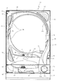
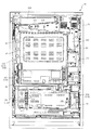
以下、本発明の実施形態について、添付図面を参照して説明する。まず、図1から図35を参照し、第1実施形態として、本発明をパチンコ遊技機(以下、単に「パチンコ機」という)10に適用した場合の一実施形態について説明する。図1は、第1実施形態におけるパチンコ機10の正面図であり、図2はパチンコ機10の遊技盤ユニット13の正面図であり、図3はパチンコ機10の背面図である。   Embodiments of the present invention will be described below with reference to the accompanying drawings. First, with reference to FIG. 1 to FIG. 35, an embodiment in which the present invention is applied to a pachinko gaming machine (hereinafter simply referred to as “pachinko machine”) 10 will be described as a first embodiment. FIG. 1 is a front view of the pachinko machine 10 according to the first embodiment, FIG. 2 is a front view of the game board unit 13 of the pachinko machine 10, and FIG. 3 is a rear view of the pachinko machine 10.

図1に示すように、パチンコ機10は、略矩形状に組み合わせた木枠により外殻が形成される外枠11と、その外枠11と略同一の外形形状に形成され外枠11に対して開閉可能に支持された内枠12とを備えている。外枠11には、内枠12を支持するために正面視(図1参照)左側の上下2カ所に金属製のヒンジ18が取り付けられ、そのヒンジ18が設けられた側を開閉の軸として内枠12が正面手前側へ開閉可能に支持される。   As shown in FIG. 1, the pachinko machine 10 includes an outer frame 11 in which an outer shell is formed by a wooden frame combined in a substantially rectangular shape, and an outer shape that is substantially the same as the outer frame 11. And an inner frame 12 supported to be openable and closable. In order to support the inner frame 12, metal hinges 18 are attached to the outer frame 11 at two upper and lower portions on the left side when viewed from the front (see FIG. 1), and the side on which the hinge 18 is provided is used as an opening / closing axis. The frame 12 is supported so as to be openable and closable to the front front side.

内枠12には、多数の釘や入賞口63,64、可変入賞装置65,650等の電気部品を有する遊技盤ユニット13(図2参照)が正面側から着脱可能に装着される。この遊技盤ユニット13(ベース板60)の前面を球(遊技球)が流下することにより弾球遊技が行われる。なお、内枠12には、球を遊技盤ユニット13の前面領域に発射する球発射ユニット112a(図4及び図5参照)やその球発射ユニット112aから発射された球を遊技盤ユニット13の前面領域まで誘導する発射レール112a1(図5参照)等が取り付けられている。   A game board unit 13 (see FIG. 2) having electrical parts such as a large number of nails, winning holes 63 and 64, and variable winning devices 65 and 650 is detachably mounted on the inner frame 12 from the front side. A ball ball game is played when a ball (game ball) flows down the front surface of the game board unit 13 (base plate 60). The inner frame 12 has a ball launch unit 112a (see FIGS. 4 and 5) that launches a ball to the front area of the game board unit 13, and a ball launched from the ball launch unit 112a. A firing rail 112a1 (see FIG. 5) and the like for guiding to the area are attached.

内枠12の前面側には、その前面上側を覆う前面枠14と、その下側を覆う下皿ユニット15とが設けられている。前面枠14及び下皿ユニット15を支持するために正面視(図1参照)左側の上下2カ所に金属製のヒンジ19が取り付けられ、そのヒンジ19が設けられた側を開閉の軸として前面枠14及び下皿ユニット15が正面手前側へ開閉可能に支持される。なお、内枠12の施錠と前面枠14の施錠とは、シリンダ錠20の鍵穴21に専用の鍵を差し込んで所定の操作を行うことでそれぞれ解除される。   On the front side of the inner frame 12, a front frame 14 that covers the upper side of the front surface and a lower dish unit 15 that covers the lower side of the front frame 14 are provided. In order to support the front frame 14 and the lower dish unit 15, metal hinges 19 are attached to two upper and lower portions on the left side when viewed from the front (see FIG. 1), and the side on which the hinges 19 are provided is used as an opening / closing axis. 14 and the lower pan unit 15 are supported so as to be openable and closable toward the front front side. The locking of the inner frame 12 and the locking of the front frame 14 are respectively released by inserting a dedicated key into the key hole 21 of the cylinder lock 20 and performing a predetermined operation.

前面枠14は、装飾用の樹脂部品や電気部品等を組み付けたものであり、その略中央部には略楕円形状に開口形成された窓部14cが設けられている。前面枠14の裏面側には2枚の板ガラスを有するガラスユニット16が配設され、そのガラスユニット16を介して遊技盤ユニット13の前面がパチンコ機10の正面側に視認可能となっている。   The front frame 14 is assembled with decorative resin parts, electrical parts, and the like, and a window part 14c that is formed in an approximately elliptical shape is provided at a substantially central part thereof. A glass unit 16 having two plate glasses is disposed on the back side of the front frame 14, and the front surface of the game board unit 13 is visible on the front side of the pachinko machine 10 through the glass unit 16.

前面枠14には、球を貯留する上皿17が前方へ張り出して上面を開放した略箱状に形成されており、この上皿17に賞球や貸出球などが排出される。上皿17の底面は正面視(図1参照)右側に下降傾斜して形成され、その傾斜により上皿17に投入された球が球発射ユニット112a(図4参照)へと案内される。また、上皿17の上面には、枠ボタン22が設けられている。この枠ボタン22は、例えば、第3図柄表示装置81(図2参照)で表示される演出のステージを変更したり、スーパーリーチの演出内容を変更したりする場合などに、遊技者により操作される。   On the front frame 14, an upper plate 17 that stores balls is formed in a substantially box shape that protrudes forward and the upper surface is opened, and prize balls and rental balls are discharged to the upper plate 17. The bottom surface of the upper plate 17 is formed to be inclined downward to the right when viewed from the front (see FIG. 1), and the sphere thrown into the upper plate 17 is guided to the ball launch unit 112a (see FIG. 4). A frame button 22 is provided on the upper surface of the upper plate 17. The frame button 22 is operated by the player when, for example, changing the stage of the effect displayed on the third symbol display device 81 (see FIG. 2) or changing the contents of the effect of super reach. The

前面枠14には、その周囲(例えばコーナー部分)に各種ランプ等の発光手段が設けられている。これら発光手段は、大当たり時や所定のリーチ時等における遊技状態の変化に応じて、点灯又は点滅することにより発光態様が変更制御され、遊技中の演出効果を高める役割を果たす。窓部14cの周縁には、LED等の発光手段を内蔵した電飾部29〜33が設けられている。パチンコ機10においては、これら電飾部29〜33が大当たりランプ等の演出ランプとして機能し、大当たり時やリーチ演出時等には内蔵するLEDの点灯や点滅によって各電飾部29〜33が点灯または点滅して、大当たり中である旨、或いは大当たり一歩手前のリーチ中である旨が報知される。また、前面枠14の正面視(図1参照)左上部には、LED等の発光手段が内蔵され賞球の払い出し中とエラー発生時とを表示可能な表示ランプ34が設けられている。   The front frame 14 is provided with light emitting means such as various lamps around it (for example, a corner portion). These light-emitting means play a role of enhancing the effect of the game during the game by changing or controlling the light-emitting mode by turning on or flashing according to the change in the gaming state at the time of big hit or predetermined reach. On the peripheral edge of the window portion 14c, there are provided electric decoration portions 29 to 33 incorporating light emitting means such as LEDs. In the pachinko machine 10, these lighting parts 29 to 33 function as effect lamps such as jackpot lamps, and the lighting parts 29 to 33 are turned on by lighting or blinking of the built-in LEDs at the time of jackpot or reach effects. Alternatively, it blinks to notify that the jackpot is being hit or that the reach is one step before the jackpot. Further, in the upper left part of the front frame 14 as viewed from the front (see FIG. 1), there is provided a display lamp 34 which has built-in light emitting means such as LEDs and can display the payout of a prize ball and when an error occurs.

また、右側の電飾部32下側には、前面枠14の裏面側を視認できるように裏面側より透明樹脂を取り付けて小窓35が形成され、遊技盤ユニット13(ベース板60)前面の貼着スペースK1(図2参照)に貼付される証紙等がパチンコ機10の前面から視認可能とされる。また、パチンコ機10においては、より煌びやかさを醸し出すために、電飾部29〜33の周りの領域にクロムメッキを施したABS樹脂製のメッキ部材36が取り付けられている。   In addition, a small window 35 is formed on the lower side of the right-side lighting part 32 by attaching a transparent resin from the back side so that the back side of the front frame 14 can be seen, and the front of the game board unit 13 (base plate 60). A stamp or the like stuck on the sticking space K1 (see FIG. 2) is visible from the front surface of the pachinko machine 10. In addition, in the pachinko machine 10, a plated member 36 made of ABS resin that is chrome-plated is attached to an area around the electric decoration parts 29 to 33 in order to bring out more gorgeousness.

窓部14cの下方には、貸球操作部40が配設される。貸球操作部40には、度数表示部41と、球貸しボタン42と、返却ボタン43とが設けられている。パチンコ機10の側方に配置されるカードユニット(球貸しユニット)(図示せず)に紙幣やカード等を投入した状態で貸球操作部40が操作されると、その操作に応じて球の貸出が行われる。具体的には、度数表示部41はカード等の残額情報が表示される領域であり、内蔵されたLEDが点灯して残額情報として残額が数字で表示される。球貸しボタン42は、カード等(記録媒体)に記録された情報に基づいて貸出球を得るために操作されるものであり、カード等に残額が存在する限りにおいて貸出球が上皿17に供給される。返却ボタン43は、カードユニットに挿入されたカード等の返却を求める際に操作される。なお、カードユニットを介さずに球貸し装置等から上皿17に球が直接貸し出されるパチンコ機、いわゆる現金機では貸球操作部40が不要となるが、この場合には、貸球操作部40の設置部分に飾りシール等を付加して部品構成は共通のものとしても良い。カードユニットを用いたパチンコ機と現金機との共通化を図ることができる。   A ball rental operation unit 40 is disposed below the window 14c. The ball lending operation unit 40 is provided with a frequency display unit 41, a ball lending button 42 and a return button 43. When the ball lending operation unit 40 is operated in a state where a bill or a card is inserted into a card unit (ball lending unit) (not shown) arranged on the side of the pachinko machine 10, Loans are made. Specifically, the frequency display unit 41 is an area in which the remaining amount information such as a card is displayed, and the built-in LED is lit to display the remaining amount as the remaining amount information. The ball lending button 42 is operated to obtain a lending ball based on information recorded on a card or the like (recording medium), and the lending ball is supplied to the upper plate 17 as long as there is a remaining amount on the card or the like. Is done. The return button 43 is operated when requesting the return of a card or the like inserted into the card unit. In addition, in a pachinko machine in which a ball is lent directly to the upper plate 17 from a ball lending device or the like without using a card unit, a so-called cash machine does not require the ball lending operation unit 40. In this case, the ball lending operation unit 40 It is also possible to add a decorative seal or the like to the installation portion of the parts so that the component configuration is common. A pachinko machine using a card unit and a cash machine can be shared.

上皿17の下側に位置する下皿ユニット15には、その中央部に上皿17に貯留しきれなかった球を貯留するための下皿50が上面を開放した略箱状に形成される。下皿50の右側には、球を遊技盤ユニット13(ベース板60)の前面へ打ち込むために遊技者によって操作される操作ハンドル51が配設される。   In the lower plate unit 15 located on the lower side of the upper plate 17, a lower plate 50 for storing balls that could not be stored in the upper plate 17 is formed in a substantially box shape with the upper surface opened at the center. . On the right side of the lower plate 50, an operation handle 51 that is operated by the player to drive the ball into the front surface of the game board unit 13 (base plate 60) is disposed.

操作ハンドル51の内部には、球発射ユニット112aの駆動を許可するためのタッチセンサ51aと、押下操作している期間中には球の発射を停止する発射停止スイッチ51bと、操作ハンドル51の回動操作量(回動位置)を電気抵抗の変化により検出する可変抵抗器(図示せず)などが内蔵される。操作ハンドル51が遊技者によって右回りに回動操作されると、タッチセンサ51aがオンされると共に可変抵抗器の抵抗値が回動操作量に対応して変化し、その可変抵抗器の抵抗値に対応した強さ(発射強度)で球が発射され、これにより遊技者の操作に対応した飛び量で遊技盤ユニット13(ベース板60)の前面へ球が打ち込まれる。また、操作ハンドル51が遊技者により操作されていない状態においては、タッチセンサ51aおよび発射停止スイッチ51bがオフとなっている。   Inside the operation handle 51, a touch sensor 51a for permitting driving of the ball launch unit 112a, a launch stop switch 51b for stopping the launch of the ball during the pressing operation, and a rotation of the operation handle 51. A variable resistor (not shown) that detects the amount of movement operation (rotation position) by a change in electrical resistance is incorporated. When the operation handle 51 is rotated clockwise by the player, the touch sensor 51a is turned on and the resistance value of the variable resistor changes in accordance with the amount of rotation operation. The resistance value of the variable resistor A ball is launched at a strength (launch strength) corresponding to, and the ball is driven into the front surface of the game board unit 13 (base plate 60) with a jump amount corresponding to the player's operation. Further, when the operation handle 51 is not operated by the player, the touch sensor 51a and the firing stop switch 51b are turned off.

下皿50の正面下方部には、下皿50に貯留された球を下方へ排出する際に操作するための球抜きレバー52が設けられている。この球抜きレバー52は、常時、右方向に付勢されており、その付勢に抗して左方向へスライドさせることにより、下皿50の底面に形成された底面口が開口して、その底面口から球が自然落下して排出される。この球抜きレバー52の操作は、通常、下皿50の下方に下皿50から排出された球を受け取る箱(一般に「千両箱」と称される)を置いた状態で行われる。下皿50の右方には、上述したように操作ハンドル51が配設され、下皿50の左方には灰皿53が取り付けられている。   In the lower part of the front of the lower plate 50, a ball removal lever 52 is provided for operating when the balls stored in the lower plate 50 are discharged downward. The ball removal lever 52 is always urged in the right direction. By sliding the ball release lever 52 in the left direction against the urge, the bottom opening formed in the bottom surface of the lower plate 50 is opened. A ball naturally falls from the bottom opening and is discharged. The operation of the ball removal lever 52 is normally performed in a state where a box (generally referred to as “a thousand box”) for receiving the balls discharged from the lower plate 50 is placed below the lower plate 50. As described above, the operation handle 51 is disposed on the right side of the lower plate 50, and the ashtray 53 is attached on the left side of the lower plate 50.

図2に示すように、遊技盤ユニット13は、正面視略正方形状に切削加工したベース板60に、球案内用の多数の釘(図示せず)や風車の他、レール61,62、一般入賞口63、第1入賞口64、第2入賞口640、第一可変入賞装置65、第2可変入賞装置650、スルーゲート67、可変表示装置ユニット80等、各種構造部品や電気部品を組み付けて構成され、その周縁部が内枠12(図1参照)に着脱可能に取り付けられる。   As shown in FIG. 2, the game board unit 13 includes a base plate 60 cut into a substantially square shape when viewed from the front, a large number of nails (not shown) for ball guidance, a windmill, rails 61 and 62, Assembling various structural parts and electrical parts such as a winning opening 63, a first winning opening 64, a second winning opening 640, a first variable winning device 65, a second variable winning device 650, a through gate 67, a variable display device unit 80, etc. It comprises, and the peripheral part is attached to the inner frame 12 (refer FIG. 1) so that attachment or detachment is possible.

ベース板60は光透過性の樹脂材料からなり、その正面側からベース板60の背面側に配設された各種構造体を遊技者に視認させることが可能に形成される。一般入賞口63、第1入賞口64、第2入賞口640、第1可変入賞装置65、第2可変入賞装置650、可変表示装置ユニット80は、ルータ加工によってベース板60に形成された貫通穴に配設され、遊技盤ユニット13のベース板60にその前面側からタッピングネジ等により固定される。   The base plate 60 is made of a light-transmitting resin material and is formed so that the player can visually recognize various structures disposed on the back side of the base plate 60 from the front side. The general winning port 63, the first winning port 64, the second winning port 640, the first variable winning device 65, the second variable winning device 650, and the variable display device unit 80 are formed in through holes formed in the base plate 60 by router processing. And is fixed to the base plate 60 of the game board unit 13 from the front side thereof with a tapping screw or the like.

遊技盤ユニット13の前面中央部分は、前面枠14の窓部14c(図1参照)を通じて内枠12の前面側から視認することができる。以下に、主に図2を参照して、遊技盤ユニット13の構成について説明する。   The front center portion of the game board unit 13 can be viewed from the front side of the inner frame 12 through the window portion 14c of the front frame 14 (see FIG. 1). The configuration of the game board unit 13 will be described below mainly with reference to FIG.

遊技盤ユニット13(ベース板60)の前面には、帯状の金属板を略円弧状に屈曲加工して形成した外レール62が植立され、その外レール62の内側位置には外レール62と同様に帯状の金属板で形成した円弧状の内レール61が植立される。この内レール61と外レール62とにより遊技盤ユニット13(ベース板60)の前面外周が囲まれ、遊技盤ユニット13(ベース板60)とガラスユニット16(図1参照)とにより前後が囲まれることにより、遊技盤ユニット13(ベース板60)の前面には、球の挙動により遊技が行われる遊技領域が形成される。遊技領域は、遊技盤ユニット13の前面であって2本のレール61,62とレール間を繋ぐ樹脂製の外縁部材73とにより区画して形成される領域(入賞口等が配設され、発射された球が流下する領域)である。   On the front surface of the game board unit 13 (base plate 60), an outer rail 62 formed by bending a belt-shaped metal plate into a substantially arc shape is planted. Similarly, an arc-shaped inner rail 61 formed of a band-shaped metal plate is planted. The inner periphery of the game board unit 13 (base plate 60) is surrounded by the inner rail 61 and the outer rail 62, and the front and rear are surrounded by the game board unit 13 (base plate 60) and the glass unit 16 (see FIG. 1). Thus, a game area where a game is played is formed on the front surface of the game board unit 13 (base plate 60) by the behavior of the ball. The game area is an area formed on the front surface of the game board unit 13 and defined by the two rails 61 and 62 and a resin outer edge member 73 that connects the rails (a winning opening is provided and fired). The area where the spheres flowed down).

2本のレール61,62は、球発射ユニット112a(図4参照)から発射された球を遊技盤ユニット13(ベース板60)上部へ案内するために設けられたものである。内レール61の先端部分(図2の左上部)には戻り球防止部材68が取り付けられ、一旦、遊技盤ユニット13の上部へ案内された球が再度球案内通路内に戻ってしまうといった事態が防止される。外レール62の先端部(図2の右上部)には、球の最大飛翔部分に対応する位置に返しゴム69が取り付けられ、所定以上の勢いで発射された球は、返しゴム69に当たって、勢いが減衰されつつ中央部側へ跳ね返される。   The two rails 61 and 62 are provided to guide the ball launched from the ball launch unit 112a (see FIG. 4) to the upper part of the game board unit 13 (base plate 60). A return ball prevention member 68 is attached to the front end portion of the inner rail 61 (upper left portion in FIG. 2), and the ball once guided to the upper portion of the game board unit 13 returns to the ball guide path again. Is prevented. A return rubber 69 is attached to the tip of the outer rail 62 (upper right part in FIG. 2) at a position corresponding to the maximum flying portion of the sphere, and the ball launched at a predetermined momentum or more hits the return rubber 69 and gains momentum. Is bounced back to the center while being attenuated.

遊技領域の正面視左側下部(図2の左側下部)には、発光手段である複数のLED及び7セグメント表示器を備える第1図柄表示装置37A,37Bが配設される。第1図柄表示装置37A,37Bは、主制御装置110(図4参照)で行われる各制御に応じた表示がなされるものであり、主にパチンコ機10の遊技状態の表示が行われる。本実施形態では、第1図柄表示装置37A,37Bは、球が、第1入賞口64へ入賞したか、第2入賞口640へ入賞したかに応じて使い分けられるように構成される。具体的には、球が、第1入賞口64へ入賞した場合には、第1図柄表示装置37Aが作動し、一方で、球が、第2入賞口640へ入賞した場合には、第1図柄表示装置37Bが作動するように構成される。   First symbol display devices 37A and 37B each having a plurality of LEDs and a 7-segment display as light emitting means are disposed in the lower left portion of the game area when viewed from the front (lower left portion in FIG. 2). The first symbol display devices 37A and 37B display according to each control performed by the main control device 110 (see FIG. 4), and mainly display the gaming state of the pachinko machine 10. In the present embodiment, the first symbol display devices 37 </ b> A and 37 </ b> B are configured to be selectively used depending on whether the ball has won the first prize opening 64 or the second prize opening 640. Specifically, when the ball wins the first winning opening 64, the first symbol display device 37A operates, while when the ball wins the second winning opening 640, the first symbol display device 37A operates. The symbol display device 37B is configured to operate.

また、第1図柄表示装置37A,37Bは、LEDにより、パチンコ機10が確変中か時短中か通常中であるかを点灯状態により示したり、変動中であるか否かを点灯状態により示したり、停止図柄が確変大当たりに対応した図柄か普通大当たりに対応した図柄か外れ図柄であるかを点灯状態により示したり、保留球数を点灯状態により示すと共に、7セグメント表示装置により、大当たり中のラウンド数やエラー表示を行う。なお、複数のLEDは、それぞれのLEDの発光色(例えば、赤、緑、青)が異なるよう構成され、その発光色の組み合わせにより、少ないLEDでパチンコ機10の各種遊技状態を示唆することができる。   In addition, the first symbol display devices 37A and 37B indicate, by means of LEDs, whether the pachinko machine 10 is in the process of changing the probability, in the short time, or in the normal state by a lighting state, or whether the pachinko machine 10 is changing or not by a lighting state. , Indicating whether the stop symbol is a symbol corresponding to a probable jackpot, a symbol corresponding to a normal jackpot, or a symbol that is out of place by a lighting state, indicating the number of held balls by a lighting state, and a 7-segment display device, Displays numbers and errors. The plurality of LEDs are configured to have different emission colors (for example, red, green, and blue) of each LED, and the combination of the emission colors may suggest various gaming states of the pachinko machine 10 with a small number of LEDs. it can.

尚、本パチンコ機10では、第1入賞口64及び第2入賞口640へ入賞があったことを契機として抽選が行われる。パチンコ機10は、その抽選において、大当たりか否かの当否判定(大当たり抽選)を行うと共に、大当たりと判定した場合はその大当たり種別の判定も行う。ここで判定される大当たり種別としては、15R確変大当たり、4R確変大当たり、15R通常大当たりが用意される。第1図柄表示装置37A,37Bには、変動終了後の停止図柄として抽選の結果が大当たりであるか否かが示されるだけでなく、大当たりである場合はその大当たり種別に応じた図柄が示される。   In the present pachinko machine 10, a lottery is performed in response to winning of the first winning port 64 and the second winning port 640. In the lottery, the pachinko machine 10 determines whether or not it is a big hit (big hit lottery), and also determines the type of the big hit if it is determined to be a big hit. As the jackpot type determined here, 15R probability variation jackpot, 4R probability variation jackpot, and 15R normal jackpot are prepared. The first symbol display devices 37A and 37B not only indicate whether or not the lottery result is a jackpot as a stop symbol after the end of the variation, but if it is a jackpot, a symbol corresponding to the jackpot type is displayed. .

ここで、「15R確変大当たり」とは、最大ラウンド数が15ラウンドの大当たりの後に高確率状態へ移行する確変大当たりのことであり、「4R確変大当たり」とは、最大ラウンド数が4ラウンドの大当たりの後に高確率状態へ移行する確変大当たりのことである。また、「15R通常大当たり」は、最大ラウンド数が15ラウンドの大当たりの後に、低確率状態へ移行すると共に、所定の変動回数の間(例えば、100変動回数)は時短状態となる大当たりのことである。   Here, the “15R probability variation jackpot” is a probability variation jackpot in which the maximum number of rounds shifts to a high probability state after a jackpot of 15 rounds, and “4R probability variation jackpot” is a jackpot with a maximum number of rounds of four. It is a probabilistic jackpot that shifts to a high probability state after. In addition, “15R normal jackpot” is a jackpot that shifts to a low probability state after the maximum number of rounds of 15 rounds and hits a short time during a predetermined number of fluctuations (for example, 100 fluctuations). is there.

また、「高確率状態」とは、大当たり終了後に付加価値としてその後の大当たり確率がアップした状態、いわゆる確率変動中(確変中)の時をいい、換言すれば、特別遊技状態へ移行し易い遊技の状態のことである。本実施形態における高確率状態(確変中)は、後述する第2図柄の当たり確率がアップして第2入賞口640へ球が入賞し易い遊技の状態を含む。「低確率状態」とは、確変中でない時をいい、大当たり確率が通常の状態、即ち、確変の時より大当たり確率が低い状態をいう。また、「低確率状態」のうちの時短状態(時短中)とは、大当たり確率が通常の状態であると共に、大当たり確率がそのままで第2図柄の当たり確率のみがアップして第2入賞口640へ球が入賞し易い遊技の状態のことをいう。一方、パチンコ機10が通常中とは、確変中でも時短中でもない遊技の状態(大当たり確率も第2図柄の当たり確率もアップしていない状態)である。   In addition, the “high probability state” means a state in which the jackpot probability thereafter increases as an added value after the jackpot ends, that is, when the probability change is in progress (probability change), in other words, a game that easily shifts to the special game state. It is a state of. The high probability state (during probability change) in the present embodiment includes a game state in which the hit probability of the second symbol, which will be described later, is increased and the ball is likely to win the second winning opening 640. The “low probability state” refers to a time when the probability of jackpot change is not occurring, and a state where the jackpot probability is normal, that is, a state where the jackpot probability is lower than that at the time of probability change. The short time state (short time medium) of the “low probability state” means that the jackpot probability is a normal state, and the jackpot probability remains as it is, and only the hit probability of the second symbol is increased, and the second prize opening 640 is obtained. It means the state of the game where the ball is easy to win. On the other hand, when the pachinko machine 10 is in a normal state is a game state (a state where neither the big hit probability nor the second symbol hit probability is increased) which is neither probabilistic nor short in time.

確変中や時短中は、第2図柄の当たり確率がアップするだけではなく、第2入賞口640に付随する電動役物640aが開放される時間も変更され、通常中と比して長い時間が設定される。電動役物640aが開放された状態(開放状態)にある場合は、その電動役物640aが閉鎖された状態(閉鎖状態)にある場合と比して、第2入賞口640へ球が入賞しやすい状態となる。よって、確変中や時短中は、第2入賞口640へ球が入賞し易い状態となり、大当たり抽選が行われる回数を増やすことができる。   During probability change and time reduction, not only does the probability of winning the second symbol increase, but also the time for opening the electric accessory 640a associated with the second prize opening 640 is changed, and the time is longer than normal. Is set. When the electric accessory 640a is in the opened state (open state), the ball wins the second winning opening 640 as compared to the case where the electric accessory 640a is in the closed state (closed state). Easy state. Therefore, during the probability change or the short time, it becomes easy for the ball to win the second winning opening 640, and the number of jackpot lotteries can be increased.

なお、確変中や時短中において、第2入賞口640に付随する電動役物640aの開放時間を変更するのではなく、または、その開放時間を変更することに加えて、1回の当たりで電動役物640aが開放する回数を通常中よりも増やす変更を行うものとしてもよい。また、確変中や時短中において、第2図柄の当たり確率は変更せず、第2入賞口640に付随する電動役物640aが開放される時間および1回の当たりで電動役物640aが開放する回数の少なくとも一方を変更するものとしてもよい。また、確変中や時短中において、第2入賞口640に付随する電動役物640aが開放される時間や、1回の当たりで電動役物640aを開放する回数はせず、第2図柄の当たり確率だけを、通常中と比してアップするよう変更するものであってもよい。   In addition, during the probability change or during the short time, it is not necessary to change the opening time of the electric accessory 640a associated with the second prize opening 640, or in addition to changing the opening time, It is good also as what changes the frequency | count that the accessory 640a opens more than usual. In addition, the probability of winning the second symbol is not changed during the probability change or in the short time, and the electric accessory 640a is released at the time when the electric accessory 640a associated with the second winning opening 640 is opened and once. It is good also as what changes at least one of the frequency | counts. In addition, during the probability change or in the short time, the time of opening the electric accessory 640a associated with the second winning opening 640 or the number of times of opening the electric accessory 640a per time is not counted, and the second symbol hit Only the probability may be changed so as to increase compared to the normal rate.

遊技領域には、球が入賞することにより5個から15個の球が賞球として払い出される複数の一般入賞口63が配設される。また、遊技領域の中央部分には、可変表示装置ユニット80が配設される。可変表示装置ユニット80には、第1入賞口64及び第2入賞口640への入賞(始動入賞)をトリガとして、第1図柄表示装置37A,37Bにおける変動表示と同期させながら、第3図柄の変動表示を行う液晶ディスプレイ(以下単に「表示装置」と略す)で構成された第3図柄表示装置81と、スルーゲート67の球の通過をトリガとして第2図柄を変動表示するLEDで構成される第2図柄表示装置(図示せず)とが設けられている。また、可変表示装置ユニット80には、第3図柄表示装置81の外周を囲むようにして、センターフレーム86が配設される。   The game area is provided with a plurality of general winning ports 63 through which 5 to 15 balls are paid out as winning balls when the balls win. In addition, a variable display device unit 80 is disposed in the central portion of the game area. The variable display device unit 80 is synchronized with the variable display on the first symbol display devices 37A and 37B by using a winning (start winning) at the first winning port 64 and the second winning port 640 as a trigger. It is composed of a third symbol display device 81 composed of a liquid crystal display (hereinafter simply referred to as “display device”) that performs variable display, and an LED that displays the second symbol in a variable manner with the passage of a sphere of the through gate 67 as a trigger. A second symbol display device (not shown) is provided. The variable display device unit 80 is provided with a center frame 86 so as to surround the outer periphery of the third symbol display device 81.

第3図柄表示装置81は9インチサイズの大型の液晶ディスプレイで構成されるものであり、表示制御装置114(図4参照)によって表示内容が制御されることにより、例えば上、中及び下の3つの図柄列が表示される。各図柄列は複数の図柄(第3図柄)によって構成され、これらの第3図柄が図柄列毎に横スクロールして第3図柄表示装置81の表示画面上にて第3図柄が可変表示されるようになっている。本実施形態の第3図柄表示装置81は、主制御装置110(図4参照)の制御に伴った遊技状態の表示が第1図柄表示装置37A,37Bで行われるのに対して、その第1図柄表示装置37A,37Bの表示に応じた装飾的な表示を行うものである。なお、表示装置に代えて、例えばリール等を用いて第3図柄表示装置81を構成するようにしても良い。   The third symbol display device 81 is constituted by a large 9-inch liquid crystal display, and the display content is controlled by the display control device 114 (see FIG. 4). One symbol row is displayed. Each symbol row is composed of a plurality of symbols (third symbol). These third symbols are horizontally scrolled for each symbol column, and the third symbol is variably displayed on the display screen of the third symbol display device 81. It is like that. In the third symbol display device 81 of the present embodiment, the game state display associated with the control of the main controller 110 (see FIG. 4) is performed on the first symbol display devices 37A and 37B. The decorative display according to the display of the symbol display devices 37A and 37B is performed. Instead of the display device, the third symbol display device 81 may be configured using, for example, a reel.

第2図柄表示装置は、球がスルーゲート67を通過する毎に表示図柄(第2図柄(図示せず))としての「○」の図柄と「×」の図柄とを所定時間交互に点灯させる変動表示を行うものである。パチンコ機10では、球がスルーゲート67を通過したことが検出されると、当たり抽選が行われる。その当たり抽選の結果、当たりであれば、第2図柄表示装置において、第2図柄の変動表示後に「○」の図柄が停止表示される。また、当たり抽選の結果、外れであれば、第2図柄表示装置において、第3図柄の変動表示後に「×」の図柄が停止表示される。   Each time the sphere passes through the through gate 67, the second symbol display device alternately turns on the symbol “◯” and the symbol “X” as a display symbol (second symbol (not shown)) for a predetermined time. A variable display is performed. In the pachinko machine 10, when it is detected that the ball has passed through the through gate 67, a winning lottery is performed. As a result of the winning lottery, if the winning symbol is a winning symbol, the symbol “◯” is stopped and displayed on the second symbol display device after the variation of the second symbol is displayed. Further, if the winning lottery results, the symbol of “x” is stopped and displayed on the second symbol display device after the variation of the third symbol is displayed.

パチンコ機10は、第2図柄表示装置における変動表示が所定図柄(本実施形態においては「○」の図柄)で停止した場合に、第2入賞口640に付随された電動役物640aが所定時間だけ作動状態となる(開放される)よう構成される。   In the pachinko machine 10, when the variable display on the second symbol display device stops at a predetermined symbol (in this embodiment, a symbol “◯”), the electric accessory 640a attached to the second winning opening 640 is displayed for a predetermined time. It is configured to be activated (opened) only.

第2図柄の変動表示にかかる時間は、遊技状態が通常中の場合よりも、確変中または時短中の方が短くなるように設定される。これにより、確変中および時短中は、第2図柄の変動表示が短い時間で行われるので、当たり抽選を通常中よりも多く行うことができる。よって、当たり抽選において当たりとなる機会が増えるので、第2入賞口640の電動役物640aが開放状態となる機会を遊技者に多く与えることができる。よって、確変中および時短中は、第2入賞口640へ球が入賞しやすい状態とすることができる。   The time required for the variable display of the second symbol is set to be shorter during the probability change or during the shorter time than when the game state is normal. As a result, during the probability change and during the time reduction, since the variation display of the second symbol is performed in a short time, the winning lottery can be performed more than during normal. Therefore, since the chance of winning in the winning lottery increases, it is possible to give the player a lot of opportunities for the electric winning component 640a of the second winning opening 640 to be in an open state. Therefore, it is possible to make it easier for the ball to win the second winning opening 640 during the probability change and during the short time.

なお、確変中または時短中において、当たり確率を高める、1回に当たりに対する電動役物640aの開放時間や開放回数を増やすなど、その他の方法によっても、確変中または時短中に第2入賞口640へ球が入賞しやすい状態としている場合は、第2図柄の変動表示にかかる時間を遊技状態にかかわらず一定としてもよい。一方、第2図柄の変動表示にかかる時間を、確変中または時短中において通常中よりも短く設定する場合は、当たり確率を遊技状態にかかわらず一定にしてもよいし、また、1回の当たりに対する電動役物640aの開放時間や開放回数を遊技状態にかかわらず一定にしてもよい。   It is to be noted that the probability of winning is increased during probability change or time reduction, and other methods such as increasing the opening time and the number of times of opening of the electric accessory 640a per hit are also used to reach the second prize opening 640 during probability change or time reduction. When the ball is in a state where it is easy to win, the time required for the variable display of the second symbol may be constant regardless of the gaming state. On the other hand, when the time required for displaying the variation of the second symbol is set shorter than normal during probability change or short time, the winning probability may be constant regardless of the gaming state, The opening time and the number of opening times of the electric accessory 640a may be constant regardless of the gaming state.

スルーゲート67は、可変表示装置ユニット80の下側の領域における右方において遊技盤に組み付けられ、遊技盤に発射された球のうち、遊技盤の右方を流下する球の一部が通過可能に構成される。スルーゲート67を球が通過すると、第2図柄の当たり抽選が行われる。当たり抽選の後、第2図柄表示装置にて変動表示を行い、当たり抽選の結果が当たりであれば、変動表示の停止図柄として「○」の図柄を表示し、当たり抽選の結果が外れであれば、変動表示の停止図柄として「×」の図柄を表示する。   The through gate 67 is assembled to the game board on the right side in the lower area of the variable display device unit 80, and a part of the ball flowing down to the right side of the game board can pass through the balls launched to the game board. Configured. When the ball passes through the through gate 67, a winning lottery of the second symbol is performed. After winning the lottery, the 2nd symbol display device displays the variation. For example, the symbol “x” is displayed as the stop symbol of the variable display.

球のスルーゲート67の通過回数は、合計で最大4回まで保留され、その保留球数が上述した第1図柄表示装置37A,37Bにより表示されると共に第2図柄保留ランプ(図示せず)においても点灯表示される。第2図柄保留ランプは、最大保留数分の4つ設けられ、第3図柄表示装置81の下方に左右対称に配設される。   The total number of passes through the through-gate 67 of the sphere is held up to a maximum of 4 times, and the number of held balls is displayed by the above-described first symbol display devices 37A and 37B and at the second symbol hold lamp (not shown). Is also displayed. Four second symbol holding lamps are provided corresponding to the maximum number of holdings, and are arranged symmetrically below the third symbol display device 81.

なお、第2図柄の変動表示は、本実施形態のように、第2図柄表示装置において複数のランプの点灯と非点灯を切り換えることにより行うものの他、第1図柄表示装置37A,37B及び第3図柄表示装置81の一部を使用して行うようにしても良い。同様に、第2図柄保留ランプの点灯を第3図柄表示装置81の一部で行うようにしても良い。また、スルーゲート67の球の通過に対する最大保留球数は4回に限定されるものでなく、3回以下、又は、5回以上の回数(例えば、8回)に設定しても良い。また、スルーゲート67の組み付け数は1つに限定されるものではなく、複数(例えば、2つ)であっても良い。また、スルーゲート67の組み付け位置は可変表示装置ユニット80の右方に限定されるものではなく、例えば、可変表示装置ユニット80の左方でも良い。また、第1図柄表示装置37A,37Bにより保留球数が示されるので、第2図柄保留ランプにより点灯表示を行わないものとしてもよい。   Note that the variable display of the second symbol is performed by switching between lighting and non-lighting of a plurality of lamps in the second symbol display device as in the present embodiment, as well as the first symbol display devices 37A, 37B and the third symbol. A part of the symbol display device 81 may be used. Similarly, the second symbol holding lamp may be turned on by a part of the third symbol display device 81. Further, the maximum number of balls held for passing through the ball of the through gate 67 is not limited to four times, and may be set to three times or less, or five times or more (for example, eight times). Further, the number of through gates 67 to be assembled is not limited to one, and may be plural (for example, two). Further, the assembly position of the through gate 67 is not limited to the right side of the variable display device unit 80, and may be the left side of the variable display device unit 80, for example. In addition, since the number of reserved balls is indicated by the first symbol display devices 37A and 37B, the second symbol hold lamp may not perform lighting display.

可変表示装置ユニット80の下方には、球が入賞し得る第1入賞口64が配設される。この第1入賞口64へ球が入賞すると遊技盤ユニット13(ベース板60)の裏面側に設けられる第1入賞口スイッチ(図示せず)がオンとなり、その第1入賞口スイッチのオンに起因して主制御装置110(図4参照)で大当たりの抽選がなされ、その抽選結果に応じた表示が第1図柄表示装置37Aで示される。   Below the variable display unit 80, a first winning port 64 through which a ball can win is disposed. When a ball wins the first winning port 64, a first winning port switch (not shown) provided on the back side of the game board unit 13 (base plate 60) is turned on, and the first winning port switch is turned on. Then, the main control device 110 (see FIG. 4) makes a big win lottery, and a display corresponding to the lottery result is shown on the first symbol display device 37A.

一方、第1入賞口64の正面視右方には、球が入賞し得る第2入賞口640が配設される。この第2入賞口640へ球が入賞すると遊技盤ユニット13(ベース板60)の裏面側に設けられる第2入賞口スイッチ(図示せず)がオンとなり、その第2入賞口スイッチのオンに起因して主制御装置110(図4参照)で大当たりの抽選がなされ、その抽選結果に応じた表示が第1図柄表示装置37Bで示される。   On the other hand, a second winning port 640 through which a ball can win is disposed on the right side of the first winning port 64 in front view. When a ball wins the second prize opening 640, a second prize opening switch (not shown) provided on the back side of the game board unit 13 (base plate 60) is turned on, and the second prize opening switch is turned on. Then, the main control device 110 (see FIG. 4) makes a big win lottery, and a display corresponding to the lottery result is shown by the first symbol display device 37B.

また、第1入賞口64および第2入賞口640は、それぞれ、球が入賞すると5個の球が賞球として払い出される入賞口の1つにもなっている。なお、本実施形態においては、第1入賞口64へ球が入賞した場合に払い出される賞球数と第2入賞口640へ球が入賞した場合に払い出される賞球数とを同じに構成したが、第1入賞口64へ球が入賞した場合に払い出される賞球数と第2入賞口640へ球が入賞した場合に払い出される賞球数とを異なる数、例えば、第1入賞口64へ球が入賞した場合に払い出される賞球数を3個とし、第2入賞口640へ球が入賞した場合に払い出される賞球数を5個として構成してもよい。   Each of the first winning port 64 and the second winning port 640 is also one of winning ports from which five balls are paid out as winning balls when a ball is won. In the present embodiment, the number of prize balls to be paid out when a ball wins the first prize opening 64 and the number of prize balls to be paid out when a ball wins the second prize slot 640 are configured to be the same. The number of prize balls to be paid out when a ball wins the first prize opening 64 is different from the number of prize balls to be paid out when a ball wins to the second prize opening 640, for example, the ball to the first prize opening 64 The number of prize balls to be paid out when a prize is won may be three, and the number of prize balls to be paid out when a ball wins the second prize opening 640 may be five.

第2入賞口640には電動役物640aが付随される。この電動役物640aは開閉可能に構成されており、通常は電動役物640aが閉鎖状態(縮小状態)となって、球が第2入賞口640へ入賞しにくい状態となっている。一方、スルーゲート67への球の通過を契機として行われる第2図柄の変動表示の結果、「○」の図柄が第2図柄表示装置に表示された場合、電動役物640aが開放状態(拡大状態)となり、球が第2入賞口640へ入賞しやすい状態となる。   The second winning port 640 is accompanied by an electric accessory 640a. The electric accessory 640a is configured to be openable and closable. Normally, the electric accessory 640a is in a closed state (reduced state), and it is difficult for the ball to win the second winning opening 640. On the other hand, when the symbol “◯” is displayed on the second symbol display device as a result of the variation display of the second symbol that is triggered by the passage of the ball to the through gate 67, the electric accessory 640a is in an open state (enlarged) State), and the ball is likely to win the second winning opening 640.

上述した通り、確変中および時短中は、通常中と比して第2図柄の当たり確率が高く、また、第2図柄の変動表示にかかる時間も短いので、第2図柄の変動表示において「○」の図柄が表示され易くなって、電動役物640aが開放状態(拡大状態)となる回数が増える。更に、確変中および時短中は、電動役物640aが開放される時間も、通常中より長くなる。よって、確変中および時短中は、通常時と比して、第2入賞口640へ球が入賞しやすい状態を作ることができる。   As described above, the probability of hitting the second symbol is higher than that during normal change during the probability change and the short time, and the time required for the variation display of the second symbol is short. "Is easily displayed, and the number of times that the electric accessory 640a is opened (enlarged) is increased. Further, during the probability change and the time reduction, the time for opening the electric accessory 640a also becomes longer than during the normal time. Therefore, it is possible to create a state where the ball is likely to win the second winning opening 640 during the probability change and during the short time compared to the normal time.

ここで、第1入賞口64に球が入賞した場合と第2入賞口640へ球が入賞した場合とで、大当たりとなる確率は、低確率状態であっても高確率状態でも同一である。しかしながら、大当たりとなった場合に選定される大当たりの種別として15R確変大当たりとなる確率は、第2入賞口640へ球が入賞した場合のほうが第1入賞口64へ球が入賞した場合よりも高く設定される。一方、第1入賞口64は、第2入賞口640にあるような電動役物は有しておらず、球が常時入賞可能な状態となっている。   Here, the probability of winning a big hit is the same in both the low probability state and the high probability state when the ball wins the first winning port 64 and when the ball wins the second winning port 640. However, the probability that the 15R probability variation jackpot is selected as the jackpot type selected when the jackpot is won is higher when the ball wins the second winning slot 640 than when the ball wins the first winning slot 64. Is set. On the other hand, the first winning port 64 does not have an electric accessory as in the second winning port 640, and is in a state where the ball can always win.

よって、通常中においては、第2入賞口640に付随する電動役物が閉鎖状態にある場合が多く、第2入賞口640に入賞しづらいので、電動役物のない第1入賞口64へ向けて、可変表示装置ユニット80の左方を球が通過するように球を発射し(所謂「左打ち」)、第1入賞口64への入賞によって大当たり抽選の機会を多く得て、大当たりとなることを狙った方が、遊技者にとって有利となる。   Therefore, during normal times, the electric winnings associated with the second winning opening 640 are often in a closed state, and it is difficult to win the second winning opening 640. Then, the ball is fired so that the ball passes to the left of the variable display device unit 80 (so-called “left-handed”), and a lot of opportunities for lottery wins are obtained by winning at the first winning opening 64, resulting in a big hit It is advantageous for the player to aim for this.

一方、確変中や時短中は、スルーゲート67に球を通過させることで、第2入賞口640に付随する電動役物640aが開放状態となりやすく、第2入賞口640に入賞しやすい状態であるので、第2入賞口640へ向けて、可変表示装置80の右方を球が通過するように球を発射し(所謂「右打ち」)、スルーゲート67を通過させて電動役物を開放状態にすると共に、第2入賞口640への入賞によって15R確変大当たりとなることを狙った方が、遊技者にとって有利となる。   On the other hand, during the probability change or during the short time, passing the ball through the through gate 67 makes it easy for the electric accessory 640a attached to the second winning opening 640 to be in an open state and to easily win the second winning opening 640. Therefore, the ball is fired toward the second prize opening 640 so that the ball passes the right side of the variable display device 80 (so-called “right-handed”), and is passed through the through gate 67 to open the electric accessory. In addition, it is more advantageous for the player to aim for a 15R probability variation jackpot by winning the second winning opening 640.

このように、本実施形態のパチンコ機10は、パチンコ機10の遊技状態(確変中であるか、時短中であるか、通常中であるか)に応じて、遊技者に対し、球の発射の仕方を「左打ち」と「右打ち」とに変えさせることができる。よって、遊技者に対して、球の打ち方に変化をもたらすことができるので、遊技を楽しませることができる。   As described above, the pachinko machine 10 according to the present embodiment launches a ball to the player in accordance with the gaming state of the pachinko machine 10 (whether it is probable, short, or normal). Can be changed between “left-handed” and “right-handed”. Thus, the player can be changed in the way the ball is hit, so that the game can be enjoyed.

第1入賞口64の下方右側には第1可変入賞装置65が配設されており、その略中央部分に横長矩形状の第1特定入賞口(大開放口)65aが設けられている。また、第1入賞口64の下方左側には第2可変入賞装置650が配設されており、その略中央部分に他の入賞口63,64,640と同程度の大きさの円形形状からなる第2特定入賞口650aが設けられている。パチンコ機10においては、第1入賞口64又は第2入賞口640への入賞に起因して行われた大当たり抽選が大当たりとなると、所定時間(変動時間)が経過した後に、大当たりの停止図柄となるよう第1図柄表示装置37A又は第1図柄表示装置37Bを点灯させると共に、その大当たりに対応した停止図柄を第3図柄表示装置81に表示させて、大当たりの発生が示される。その後、球が入賞し易い特別遊技状態(大当たり)に遊技状態が遷移する。この特別遊技状態として、通常時には閉鎖される特定入賞口65a,650aが、所定時間(例えば、30秒経過するまで、或いは、球が10個入賞するまで)開放される。   A first variable winning device 65 is disposed on the lower right side of the first winning port 64, and a horizontally elongated first specific winning port (large opening port) 65a is provided at a substantially central portion thereof. Further, a second variable winning device 650 is disposed on the lower left side of the first winning port 64, and has a circular shape having the same size as the other winning ports 63, 64, and 640 at a substantially central portion thereof. A second specific winning opening 650a is provided. In the pachinko machine 10, when the jackpot lottery performed due to the winning at the first winning port 64 or the second winning port 640 becomes a jackpot, after a predetermined time (variable time) has passed, The first symbol display device 37A or the first symbol display device 37B is turned on, and a stop symbol corresponding to the jackpot is displayed on the third symbol display device 81 to indicate the occurrence of the jackpot. Thereafter, the gaming state transitions to a special gaming state (big hit) where the ball is easy to win. In this special gaming state, the special winning openings 65a and 650a that are normally closed are opened for a predetermined time (for example, until 30 seconds have elapsed or 10 balls have been won).

この特定入賞口65a,650aは、所定時間が経過すると閉鎖され、その閉鎖後、再度、その特定入賞口65a,650aが所定時間開放される。この特定入賞口65a,650aの開閉動作は、最高で例えば15回(15ラウンド)繰り返し可能にされる。この開閉動作が行われている状態が、遊技者にとって有利な特別遊技状態の一形態であり、遊技者には、遊技上の価値(遊技価値)の付与として通常時より多量の賞球の払い出しが行われる。   The specific winning ports 65a and 650a are closed when a predetermined time elapses, and after the closing, the specific winning ports 65a and 650a are opened again for a predetermined time. The opening / closing operation of the specific winning ports 65a and 650a can be repeated up to 15 times (15 rounds), for example. The state in which the opening / closing operation is performed is one form of a special gaming state that is advantageous to the player. Is done.

第1可変入賞装置65は、具体的には、第1特定入賞口65aを覆う横長矩形状の開閉板と、その開閉板の下辺を軸として前方側に開閉駆動するための大開放口ソレノイド(図示せず)とを備えている。第1特定入賞口65aは、通常時は、球が入賞できないか又は入賞し難い閉状態になっている。大当たりの際には大開放口ソレノイドを駆動して開閉板を前面下側に傾倒し、球が第1特定入賞口65aに入賞しやすい開状態を一時的に形成し、その開状態と通常時の閉状態との状態を交互に繰り返すように作動する。   Specifically, the first variable winning device 65 includes a horizontally-long rectangular opening / closing plate covering the first specific winning opening 65a, and a large opening solenoid for driving the opening / closing operation forward with the lower side of the opening / closing plate as an axis. (Not shown). The first specific winning opening 65a is normally in a closed state where the ball cannot win or is difficult to win. In the case of a big win, the large opening opening solenoid is driven to tilt the opening / closing plate downward, and the ball is temporarily formed in an open state in which it is easy to win the first specific winning opening 65a. It operates so as to alternately repeat the closed state and the closed state.

第2可変入賞装置650は、具体的には、第2特定入賞口650aへ球を案内する案内路と、その案内路の第2特定入賞口650a側とは反対側となる開口部である開口651と、その開口651の開放および閉鎖を行うための駆動役物650bと、その駆動役物650bを開口651の下辺を軸に左右方向に開閉駆動するための小開放口ソレノイド(図示せず)とを備えている。第2特定入賞口650aは、通常時は、球が入賞できないか又は入賞し難い閉状態になっている。大当たりの際には小開放口ソレノイドを駆動して駆動役物650bを右方に傾倒し、球が第2特定入賞口650aに入賞しやすい開状態を一時的に形成し、その開状態と通常時の閉状態との状態を交互に繰り返すように作動する。   Specifically, the second variable winning device 650 is an opening that is a guide path that guides the ball to the second specific winning port 650a and an opening that is on the opposite side of the guide path from the second specific winning port 650a side. 651, a driving member 650b for opening and closing the opening 651, and a small opening solenoid (not shown) for driving the driving member 650b to open and close in the horizontal direction about the lower side of the opening 651 And. The second specific winning opening 650a is normally in a closed state where the ball cannot win or is difficult to win. In the case of a big hit, the small opening opening solenoid is driven to tilt the driving tool 650b to the right, and an open state in which the ball is likely to win the second specific winning opening 650a is temporarily formed. It operates so as to alternately repeat the state of closed time.

なお、上記した形態に特別遊技状態は限定されるものではない。特定入賞口65a,650aとは別に開閉される大開放口を遊技領域に設け、第1図柄表示装置37A,37Bにおいて大当たりに対応したLEDが点灯した場合に、特定入賞口65a,650aが所定時間開放され、その特定入賞口65a,650aの開放中に、球が特定入賞口65a,650a内へ入賞することを契機として特定入賞口65a,650aとは別に設けられた大開放口が所定時間、所定回数開放される遊技状態を特別遊技状態として形成するようにしても良い。また、特定入賞口65a,650aは1つに限るものではなく、1つ若しくは2以上の複数(例えば3つ)を配置しても良く、また配置位置も第1入賞口64の下方右側や、第1入賞口64の下方左側に限らず、例えば、可変表示装置ユニット80の左方でも良い。   Note that the special gaming state is not limited to the above-described form. When the game area is provided with a large opening that can be opened and closed separately from the specific winning openings 65a and 650a, and the LED corresponding to the jackpot is turned on in the first symbol display devices 37A and 37B, the specific winning openings 65a and 650a are set for a predetermined time. A large opening provided separately from the specific winning ports 65a and 650a is triggered for a predetermined time when the ball wins into the specific winning ports 65a and 650a while the specific winning ports 65a and 650a are opened. A gaming state that is released a predetermined number of times may be formed as a special gaming state. Further, the number of the specific winning openings 65a and 650a is not limited to one, and one or a plurality of plural (for example, three) may be arranged, and the arrangement position is the lower right side of the first winning opening 64, For example, the left side of the variable display unit 80 is not limited to the lower left side of the first winning port 64.

遊技盤ユニット13(ベース板60)の下側における右隅部には、証紙や識別ラベル等を貼着するための貼着スペースK1が設けられ、貼着スペースK1に貼られた証紙等は、前面枠14の小窓35(図1参照)を通じて視認することができる。   In the right corner of the lower side of the game board unit 13 (base plate 60), an adhering space K1 for adhering a certificate paper, an identification label or the like is provided. It can be visually recognized through a small window 35 (see FIG. 1) of the front frame 14.

遊技盤ユニット13(ベース板60)には、第1アウト口71及び第2アウト口72が設けられている。遊技領域を流下する球であって、いずれの入賞口63,64,65a,640,650aにも入賞しなかった球は、第1アウト口71又は第2アウト口72を通って図示しない球排出路へと案内される。第1アウト口71は、第1入賞口64の下方に配設される一方、第2アウト口72は、第2特定入賞口650aの左側に配設される。即ち、第2アウト口72は、第2特定入賞口650aを挟んで第1アウト口71の反対側に配設される。   The game board unit 13 (base plate 60) is provided with a first out port 71 and a second out port 72. Balls that flow down the game area and have not won any of the winning holes 63, 64, 65a, 640, 650a are discharged through the first out port 71 or the second out port 72 (not shown). Guided to the road. The first out port 71 is disposed below the first winning port 64, while the second out port 72 is disposed on the left side of the second specific winning port 650a. That is, the second out port 72 is disposed on the opposite side of the first out port 71 with the second specific winning port 650a interposed therebetween.

よって、遊技領域を流下する球であって、第2特定入賞口650aよりも正面視右側(図2右側)において遊技領域の下端(内レール61又は外縁部材73)に達した球は、内レール61又は外縁部材73の傾斜に沿って流下され、第1アウト口71を通って球排出路へ案内される一方、第2特定入賞口650aよりも正面視左側において遊技領域の下端(内レール61)に達した球は、内レール61の傾斜(湾曲)に沿って流下され、第2アウト口72を通って球排出路へ案内される。   Therefore, a sphere that flows down the game area and reaches the lower end (inner rail 61 or outer edge member 73) of the game area on the right side (right side in FIG. 2) in front of the second specific prize opening 650a, 61 or the outer edge member 73 is flowed along the inclination of the outer edge member 73 and guided to the ball discharge path through the first out port 71, while the lower end of the game area (inner rail 61 on the left side of the front view from the second specific winning port 650a ) That has reached () flows down along the inclination (curvature) of the inner rail 61 and is guided to the ball discharge path through the second out port 72.

遊技盤ユニット13(ベース板60)には、球の落下方向を適宜分散、調整等するために多数の釘が植設されるとともに、風車等の各種部材(役物)とが配設される。   In the game board unit 13 (base plate 60), a large number of nails are planted to disperse and adjust the falling direction of the ball as appropriate, and various members (servants) such as a windmill are arranged. .

図3に示すように、パチンコ機10の背面側には、制御基板ユニット90,91と、裏パックユニット94とが主に備えられている。制御基板ユニット90は、主基板(主制御装置110)と音声ランプ制御基板(音声ランプ制御装置113)と表示制御基板(表示制御装置114)とが搭載されてユニット化される。制御基板ユニット91は、払出制御基板(払出制御装置111)と発射制御基板(発射制御装置112)と電源基板(電源装置115)とカードユニット接続基板116とが搭載されてユニット化される。   As shown in FIG. 3, control board units 90 and 91 and a back pack unit 94 are mainly provided on the back side of the pachinko machine 10. The control board unit 90 is unitized by mounting a main board (main control apparatus 110), an audio lamp control board (audio lamp control apparatus 113), and a display control board (display control apparatus 114). The control board unit 91 is unitized by mounting a payout control board (payout control apparatus 111), a firing control board (launching control apparatus 112), a power supply board (power supply apparatus 115), and a card unit connection board 116.

裏パックユニット94は、保護カバー部を形成する裏パック92と払出ユニット93とがユニット化される。また、各制御基板には、各制御を司る1チップマイコンとしてのMPU、各種機器との連絡をとるポート、各種抽選の際に用いられる乱数発生器、時間計数や同期を図る場合などに使用されるクロックパルス発生回路等が、必要に応じて搭載される。   In the back pack unit 94, a back pack 92 and a dispensing unit 93 forming a protective cover portion are unitized. In addition, each control board is used for MPU as a one-chip microcomputer that controls each control, a port for communicating with various devices, a random number generator used for various lotteries, time counting and synchronization. A clock pulse generation circuit or the like is mounted as necessary.

なお、主制御装置110、音声ランプ制御装置113及び表示制御装置114、払出制御装置111及び発射制御装置112、電源装置115、カードユニット接続基板116は、それぞれ基板ボックス100〜104に収納される。基板ボックス100〜104は、ボックスベースと該ボックスベースの開口部を覆うボックスカバーとを備えており、そのボックスベースとボックスカバーとが互いに連結されて、各制御装置や各基板が収納される。   The main control device 110, the sound lamp control device 113 and the display control device 114, the payout control device 111 and the firing control device 112, the power supply device 115, and the card unit connection board 116 are housed in the board boxes 100 to 104, respectively. The board boxes 100 to 104 include a box base and a box cover that covers the opening of the box base. The box base and the box cover are connected to each other, and each control device and each board are accommodated.

また、基板ボックス100(主制御装置110)及び基板ボックス102(払出制御装置111及び発射制御装置112)は、ボックスベースとボックスカバーとを封印ユニット(図示せず)によって開封不能に連結(かしめ構造による連結)している。また、ボックスベースとボックスカバーとの連結部には、ボックスベースとボックスカバーとに亘って封印シール(図示せず)が貼着される。この封印シールは、脆性な素材で構成されており、基板ボックス100,102を開封するために封印シールを剥がそうとしたり、基板ボックス100,102を無理に開封しようとすると、ボックスベース側とボックスカバー側とに切断される。よって、封印ユニット又は封印シールを確認することで、基板ボックス100,102が開封されたかどうかを知ることができる。   Further, the substrate box 100 (main control device 110) and the substrate box 102 (dispensing control device 111 and launch control device 112) connect the box base and the box cover so that they cannot be opened by a sealing unit (not shown) (caulking structure). Consolidated). In addition, a seal seal (not shown) is attached to the connecting portion between the box base and the box cover over the box base and the box cover. This seal seal is made of a brittle material. If the seal is to be peeled off in order to open the substrate boxes 100, 102, or if the substrate boxes 100, 102 are forcibly opened, the box base side and the box cover are removed. Cut to the side. Therefore, it is possible to know whether or not the substrate boxes 100 and 102 have been opened by checking the sealing unit or the sealing seal.

払出ユニット93は、裏パックユニット94の最上部に位置して上方に開口したタンク130と、タンク130の下方に連結され下流側に向けて緩やかに傾斜するタンクレール131と、タンクレール131の下流側に縦向きに連結されるケースレール132と、ケースレール132の最下流部に設けられ、払出モータ216(図4参照)の所定の電気的構成により球の払出を行う払出装置133とを備えている。タンク130には、遊技ホールの島設備から供給される球が逐次補給され、払出装置133により必要個数の球の払い出しが適宜行われる。タンクレール131には、当該タンクレール131に振動を付加するためのバイブレータ134が取り付けられている。   The payout unit 93 includes a tank 130 that is located at the top of the back pack unit 94 and opens upward, a tank rail 131 that is connected to the lower side of the tank 130 and is gently inclined toward the downstream side, and downstream of the tank rail 131. A case rail 132 that is vertically connected to the side, and a payout device 133 that is provided at the most downstream portion of the case rail 132 and that pays out a ball by a predetermined electrical configuration of the payout motor 216 (see FIG. 4). ing. Balls supplied from the island facilities of the game hall are sequentially replenished to the tank 130, and a required number of balls are paid out by the payout device 133 as appropriate. A vibrator 134 for applying vibration to the tank rail 131 is attached to the tank rail 131.

また、払出制御装置111には状態復帰スイッチ120が設けられ、発射制御装置112には可変抵抗器の操作つまみ121が設けられ、電源装置115にはRAM消去スイッチ122が設けられている。状態復帰スイッチ120は、例えば、払出モータ216(図4参照)部の球詰まり等、払出エラーの発生時に球詰まりを解消(正常状態への復帰)するために操作される。操作つまみ121は、発射ソレノイドの発射力を調整するために操作される。RAM消去スイッチ122は、パチンコ機10を初期状態に戻したい場合に電源投入時に操作される。   The payout control device 111 is provided with a state return switch 120, the firing control device 112 is provided with a variable resistor operation knob 121, and the power supply device 115 is provided with a RAM erase switch 122. The state return switch 120 is operated, for example, to eliminate ball clogging (return to a normal state) when a payout error occurs, such as ball clogging in the payout motor 216 (see FIG. 4). The operation knob 121 is operated to adjust the firing force of the firing solenoid. The RAM erase switch 122 is operated when the power is turned on to return the pachinko machine 10 to the initial state.

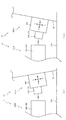
次に、図4を参照して、本パチンコ機10の電気的構成について説明する。図4は、パチンコ機10の電気的構成を示すブロック図である。   Next, the electrical configuration of the pachinko machine 10 will be described with reference to FIG. FIG. 4 is a block diagram showing an electrical configuration of the pachinko machine 10.

主制御装置110には、演算装置である1チップマイコンとしてのMPU201が搭載される。MPU201には、該MPU201により実行される各種の制御プログラムや固定値データを記憶したROM202と、そのROM202内に記憶される制御プログラムの実行に際して各種のデータ等を一時的に記憶するためのメモリであるRAM203と、そのほか、割込回路やタイマ回路、データ送受信回路などの各種回路が内蔵される。主制御装置110では、MPU201によって、大当たり抽選や第1図柄表示装置37A,37B及び第3図柄表示装置81における表示の設定、第2図柄表示装置における表示結果の抽選といったパチンコ機10の主要な処理を実行する。   The main controller 110 is equipped with an MPU 201 as a one-chip microcomputer that is an arithmetic unit. The MPU 201 includes a ROM 202 that stores various control programs executed by the MPU 201 and fixed value data, and a memory that temporarily stores various data when the control program stored in the ROM 202 is executed. A certain RAM 203 and other various circuits such as an interrupt circuit, a timer circuit, and a data transmission / reception circuit are incorporated. In the main control device 110, the main processing of the pachinko machine 10 such as jackpot lottery, display setting in the first symbol display devices 37A and 37B and the third symbol display device 81, and lottery of display results in the second symbol display device are performed by the MPU 201. Execute.

なお、払出制御装置111や音声ランプ制御装置113などのサブ制御装置に対して動作を指示するために、主制御装置110から該サブ制御装置へ各種のコマンドがデータ送受信回路によって送信されるが、かかるコマンドは、主制御装置110からサブ制御装置へ一方向にのみ送信される。   Various commands are transmitted from the main control device 110 to the sub control device by the data transmission / reception circuit in order to instruct the sub control device such as the payout control device 111 and the sound lamp control device 113 to operate. Such a command is transmitted from the main controller 110 to the sub controller only in one direction.

RAM203は、各種エリア、カウンタ、フラグのほか、MPU201の内部レジスタの内容やMPU201により実行される制御プログラムの戻り先番地などが記憶されるスタックエリアと、各種のフラグおよびカウンタ、I/O等の値が記憶される作業エリア(作業領域)とを有している。なお、RAM203は、パチンコ機10の電源の遮断後においても電源装置115からバックアップ電圧が供給されてデータを保持(バックアップ)できる構成となっており、RAM203に記憶されるデータは、すべてバックアップされる。   The RAM 203 stores various areas, counters, flags, a stack area for storing the contents of the internal registers of the MPU 201 and a return address of a control program executed by the MPU 201, various flags, counters, I / O, and the like. And a work area (work area) in which values are stored. Note that the RAM 203 is configured so that the backup voltage is supplied from the power supply device 115 and the data can be retained (backed up) even after the power of the pachinko machine 10 is shut off, and all data stored in the RAM 203 is backed up. .

停電などの発生により電源が遮断されると、その電源遮断時(停電発生時を含む。以下同様)のスタックポインタや、各レジスタの値がRAM203に記憶される。一方、電源投入時(停電解消による電源投入を含む。以下同様)には、RAM203に記憶される情報に基づいて、パチンコ機10の状態が電源遮断前の状態に復帰される。RAM203への書き込みはメイン処理(図示せず)によって電源遮断時に実行され、RAM203に書き込まれた各値の復帰は電源投入時の立ち上げ処理(図示せず)において実行される。なお、MPU201のNMI端子(ノンマスカブル割込端子)には、停電等の発生による電源遮断時に、停電監視回路252からの停電信号SG1が入力されるように構成されており、その停電信号SG1がMPU201へ入力されると、停電時処理としてのNMI割込処理(図示せず)が即座に実行される。   When the power is shut down due to the occurrence of a power failure or the like, the stack pointer and the value of each register when the power is shut off (including when the power failure occurs, the same applies hereinafter) are stored in the RAM 203. On the other hand, at the time of power-on (including power-on due to power failure cancellation, the same applies hereinafter), the state of the pachinko machine 10 is restored to the state before power-off based on information stored in the RAM 203. Writing to the RAM 203 is executed when the power is shut off by a main process (not shown), and restoration of each value written to the RAM 203 is executed in a start-up process (not shown) when the power is turned on. Note that the power failure signal SG1 from the power failure monitoring circuit 252 is input to the NMI terminal (non-maskable interrupt terminal) of the MPU 201 when the power is interrupted due to the occurrence of a power failure or the like. Is input immediately, an NMI interrupt process (not shown) as a power failure process is immediately executed.

主制御装置110のMPU201には、アドレスバス及びデータバスで構成されるバスライン204を介して入出力ポート205が接続される。入出力ポート205には、払出制御装置111、音声ランプ制御装置113、第1図柄表示装置37A,37B、第2図柄表示装置、第2図柄保留ランプ、特定入賞口65aの開閉板の下辺を軸として前方側に開閉駆動するための大開放口ソレノイドや電動役物を駆動するためのソレノイドなどからなるソレノイド209が接続され、MPU201は、入出力ポート205を介してこれらに対し各種コマンドや制御信号を送信する。   An input / output port 205 is connected to the MPU 201 of the main control device 110 via a bus line 204 constituted by an address bus and a data bus. The input / output port 205 has a payout control device 111, an audio lamp control device 113, first symbol display devices 37A and 37B, a second symbol display device, a second symbol holding lamp, and a lower side of the opening / closing plate of the specific winning opening 65a. A solenoid 209 made up of a large opening solenoid for opening and closing the front side and a solenoid for driving an electric accessory is connected to the MPU 201 via the input / output port 205. Send.

また、入出力ポート205には、図示しないスイッチ群およびスライド位置検出センサSや回転位置検出センサRを含むセンサ群などからなる各種スイッチ208、電源装置115に設けられた後述のRAM消去スイッチ回路253が接続され、MPU201は各種スイッチ208から出力される信号や、RAM消去スイッチ回路253より出力されるRAM消去信号SG2に基づいて各種処理を実行する。   The input / output port 205 includes a switch group (not shown), various switches 208 including a sensor group including a slide position detection sensor S and a rotation position detection sensor R, and a RAM erase switch circuit 253 described later provided in the power supply device 115. Are connected, and the MPU 201 executes various processes based on signals output from the various switches 208 and the RAM erase signal SG2 output from the RAM erase switch circuit 253.

払出制御装置111は、払出モータ216を駆動させて賞球や貸出球の払出制御を行うものである。演算装置であるMPU211は、そのMPU211により実行される制御プログラムや固定値データ等を記憶したROM212と、ワークメモリ等として使用されるRAM213とを有している。   The payout control device 111 drives the payout motor 216 to perform payout control of prize balls and rental balls. The MPU 211, which is an arithmetic unit, includes a ROM 212 that stores a control program executed by the MPU 211, fixed value data, and the like, and a RAM 213 that is used as a work memory or the like.

払出制御装置111のRAM213は、主制御装置110のRAM203と同様に、MPU211の内部レジスタの内容やMPU211により実行される制御プログラムの戻り先番地などが記憶されるスタックエリアと、各種のフラグおよびカウンタ、I/O等の値が記憶される作業エリア(作業領域)とを有している。RAM213は、パチンコ機10の電源の遮断後においても電源装置115からバックアップ電圧が供給されてデータを保持(バックアップ)できる構成となっており、RAM213に記憶されるデータは、すべてバックアップされる。なお、主制御装置110のMPU201と同様、MPU211のNMI端子にも、停電等の発生による電源遮断時に停電監視回路252から停電信号SG1が入力されるように構成されており、その停電信号SG1がMPU211へ入力されると、停電時処理としてのNMI割込処理(図示せず)が即座に実行される。   The RAM 213 of the payout control device 111, like the RAM 203 of the main control device 110, has a stack area for storing the contents of the internal registers of the MPU 211, the return address of the control program executed by the MPU 211, and various flags and counters. And a work area (work area) in which values such as I / O are stored. The RAM 213 is configured to be able to retain (backup) data by being supplied with a backup voltage from the power supply device 115 even after the power of the pachinko machine 10 is cut off, and all data stored in the RAM 213 is backed up. As with the MPU 201 of the main controller 110, the power failure signal SG1 is also input to the NMI terminal of the MPU 211 from the power failure monitoring circuit 252 when the power is interrupted due to the occurrence of a power failure or the like. When input to the MPU 211, an NMI interrupt process (not shown) as a power failure process is immediately executed.

払出制御装置111のMPU211には、アドレスバス及びデータバスで構成されるバスライン214を介して入出力ポート215が接続される。入出力ポート215には、主制御装置110や払出モータ216、発射制御装置112などがそれぞれ接続される。また、図示はしないが、払出制御装置111には、払い出された賞球を検出するための賞球検出スイッチが接続される。なお、該賞球検出スイッチは、払出制御装置111に接続されるが、主制御装置110には接続されていない。   An input / output port 215 is connected to the MPU 211 of the payout control device 111 via a bus line 214 constituted by an address bus and a data bus. Main controller 110, payout motor 216, launch controller 112, and the like are connected to input / output port 215, respectively. Although not shown, the payout control device 111 is connected to a prize ball detection switch for detecting a prize ball that has been paid out. The prize ball detection switch is connected to the payout control device 111 but is not connected to the main control device 110.

発射制御装置112は、主制御装置110により球の発射の指示がなされた場合に、操作ハンドル51の回動操作量に応じた球の打ち出し強さとなるよう球発射ユニット112aを制御するものである。球発射ユニット112aは、図示しない発射ソレノイドおよび電磁石を備えており、その発射ソレノイドおよび電磁石は、所定条件が整っている場合に駆動が許可される。具体的には、遊技者が操作ハンドル51に触れていることをタッチセンサ51aにより検出し、球の発射を停止させるための発射停止スイッチ51bがオフ(操作されていないこと)を条件に、操作ハンドル51の回動操作量(回動位置)に対応して発射ソレノイドが励磁され、操作ハンドル51の操作量に応じた強さで球が発射される。   The launch control device 112 controls the ball launch unit 112a so that the launch strength of the ball according to the rotation operation amount of the operation handle 51 is obtained when the main control device 110 gives an instruction to launch a ball. . The ball launching unit 112a includes a launching solenoid and an electromagnet (not shown), and the firing solenoid and the electromagnet are permitted to be driven when predetermined conditions are met. Specifically, the touch sensor 51a detects that the player is touching the operation handle 51, and the operation is performed on the condition that the launch stop switch 51b for stopping the launch of the ball is off (not operated). The firing solenoid is excited corresponding to the amount of rotation (rotation position) of the handle 51, and a ball is launched with a strength corresponding to the amount of operation of the operation handle 51.

音声ランプ制御装置113は、音声出力装置(図示しないスピーカなど)226における音声の出力、ランプ表示装置(電飾部29〜33、表示ランプ34など)227における点灯および消灯の出力、変動演出(変動表示)や予告演出といった表示制御装置114で行われる第3図柄表示装置81の表示態様の設定などを制御するものである。演算装置であるMPU221は、そのMPU221により実行される制御プログラムや固定値データ等を記憶したROM222と、ワークメモリ等として使用されるRAM223とを有している。   The sound lamp control device 113 outputs sound in a sound output device (such as a speaker (not shown)) 226, outputs lighting and extinguishing in a lamp display device (lighting units 29 to 33, display lamp 34, etc.) 227, and fluctuating effects (fluctuation). Display) and setting of the display mode of the third symbol display device 81 performed by the display control device 114 such as a notice effect. The MPU 221 that is an arithmetic unit includes a ROM 222 that stores a control program executed by the MPU 221, fixed value data, and the like, and a RAM 223 that is used as a work memory or the like.

音声ランプ制御装置113のMPU221には、アドレスバス及びデータバスで構成されるバスライン224を介して入出力ポート225が接続される。入出力ポート225には、主制御装置110、表示制御装置114、音声出力装置226、ランプ表示装置227、その他装置228、枠ボタン22などがそれぞれ接続される。その他装置228には、駆動モータ340,430,522,640,740,830が含まれる。   An input / output port 225 is connected to the MPU 221 of the sound lamp control device 113 via a bus line 224 including an address bus and a data bus. Main controller 110, display controller 114, audio output device 226, lamp display device 227, other device 228, frame button 22 and the like are connected to input / output port 225, respectively. Other devices 228 include drive motors 340, 430, 522, 640, 740, 830.

音声ランプ制御装置113は、主制御装置110から受信した各種のコマンド(変動パターンコマンド、停止種別コマンド等)に基づいて、第3図柄表示装置81の表示態様を決定し、決定した表示態様をコマンド(表示用変動パターンコマンド、表示用停止種別コマンド等)によって表示制御装置114へ通知する。また、音声ランプ制御装置113は、枠ボタン22からの入力を監視し、遊技者によって枠ボタン22が操作された場合は、第3図柄表示装置81で表示されるステージを変更したり、スーパーリーチ時の演出内容を変更したりするように、表示制御装置114へ指示する。ステージが変更される場合は、変更後のステージに応じた背面画像を第3図柄表示装置81に表示させるべく、変更後のステージに関する情報を含めた背面画像変更コマンドを表示制御装置114へ送信する。ここで、背面画像とは、第3図柄表示装置81に表示させる主要な画像である第3図柄の背面側に表示される画像のことである。表示制御装置114は、この音声ランプ制御装置113から送信されるコマンドに従って、第3図柄表示装置81に各種の画像を表示する。   The sound lamp control device 113 determines the display mode of the third symbol display device 81 based on various commands (variation pattern command, stop type command, etc.) received from the main control device 110, and uses the determined display mode as a command. The display control device 114 is notified by (display variation pattern command, display stop type command, etc.). The sound lamp control device 113 monitors the input from the frame button 22, and when the player operates the frame button 22, the stage displayed on the third symbol display device 81 is changed, or the super reach is performed. The display control device 114 is instructed to change the production contents at the time. When the stage is changed, a rear image change command including information about the changed stage is transmitted to the display control device 114 so that the rear image corresponding to the changed stage is displayed on the third symbol display device 81. . Here, the back image is an image displayed on the back side of the third symbol, which is a main image displayed on the third symbol display device 81. The display control device 114 displays various images on the third symbol display device 81 according to the command transmitted from the sound lamp control device 113.

また、音声ランプ制御装置113は、表示制御装置114から第3図柄表示装置81の表示内容を表すコマンド(表示コマンド)を受信する。音声ランプ制御装置113では、表示制御装置114から受信した表示コマンドに基づき、第3図柄表示装置81の表示内容に合わせて、その表示内容に対応する音声を音声出力装置226から出力し、また、その表示内容に対応させてランプ表示装置227の点灯および消灯を制御する。   Further, the sound lamp control device 113 receives a command (display command) representing the display content of the third symbol display device 81 from the display control device 114. The voice lamp control device 113 outputs the voice corresponding to the display content from the voice output device 226 in accordance with the display content of the third symbol display device 81 based on the display command received from the display control device 114, The lighting and extinguishing of the lamp display device 227 are controlled in accordance with the display contents.

表示制御装置114は、音声ランプ制御装置113及び第3図柄表示装置81が接続され、音声ランプ制御装置113より受信したコマンドに基づいて、第3図柄表示装置81における第3図柄の変動演出などの表示を制御するものである。また、表示制御装置114は、第3図柄表示装置81の表示内容を通知する表示コマンドを適宜音声ランプ制御装置113へ送信する。音声ランプ制御装置113は、この表示コマンドによって示される表示内容にあわせて音声出力装置226から音声を出力することで、第3図柄表示装置81の表示と音声出力装置226からの音声出力とをあわせることができる。   The display control device 114 is connected to the sound lamp control device 113 and the third symbol display device 81, and based on a command received from the sound lamp control device 113, the third symbol display device 81 can produce a variation effect of the third symbol. The display is controlled. Further, the display control device 114 appropriately transmits a display command for notifying the display content of the third symbol display device 81 to the sound lamp control device 113. The voice lamp control device 113 outputs the voice from the voice output device 226 in accordance with the display content indicated by the display command, thereby matching the display of the third symbol display device 81 with the voice output from the voice output device 226. be able to.

電源装置115は、パチンコ機10の各部に電源を供給するための電源部251と、停電等による電源遮断を監視する停電監視回路252と、RAM消去スイッチ122(図3参照)が設けられたRAM消去スイッチ回路253とを有している。電源部251は、図示しない電源経路を通じて、各制御装置110〜114等に対して各々に必要な動作電圧を供給する装置である。その概要としては、電源部251は、外部より供給される交流24ボルトの電圧を取り込み、各種スイッチ208などの各種スイッチや、ソレノイド209などのソレノイド、モータ等を駆動するための12ボルトの電圧、ロジック用の5ボルトの電圧、RAMバックアップ用のバックアップ電圧などを生成し、これら12ボルトの電圧、5ボルトの電圧及びバックアップ電圧を各制御装置110〜114等に対して必要な電圧を供給する。   The power supply device 115 includes a power supply unit 251 for supplying power to each unit of the pachinko machine 10, a power failure monitoring circuit 252 for monitoring power interruption due to a power failure, and a RAM deletion switch 122 (see FIG. 3). And an erasing switch circuit 253. The power supply unit 251 is a device that supplies a necessary operating voltage to each of the control devices 110 to 114 through a power supply path (not shown). As its outline, the power supply unit 251 takes in the voltage of AC 24 volts supplied from the outside, and drives various switches such as various switches 208, solenoids such as the solenoid 209, motors, etc. A 5 volt voltage for logic, a backup voltage for RAM backup, and the like are generated, and the 12 volt voltage, the 5 volt voltage, and the backup voltage are supplied to the control devices 110 to 114 as necessary voltages.

停電監視回路252は、停電等の発生による電源遮断時に、主制御装置110のMPU201及び払出制御装置111のMPU211の各NMI端子へ停電信号SG1を出力するための回路である。停電監視回路252は、電源部251から出力される最大電圧である直流安定24ボルトの電圧を監視し、この電圧が22ボルト未満になった場合に停電(電源断、電源遮断)の発生と判断して、停電信号SG1を主制御装置110及び払出制御装置111へ出力する。停電信号SG1の出力によって、主制御装置110及び払出制御装置111は、停電の発生を認識し、NMI割込処理を実行する。なお、電源部251は、直流安定24ボルトの電圧が22ボルト未満になった後においても、NMI割込処理の実行に充分な時間の間、制御系の駆動電圧である5ボルトの電圧の出力を正常値に維持するように構成される。よって、主制御装置110及び払出制御装置111は、NMI割込処理(図示せず)を正常に実行し完了することができる。   The power failure monitoring circuit 252 is a circuit for outputting a power failure signal SG1 to each NMI terminal of the MPU 201 of the main control device 110 and the MPU 211 of the payout control device 111 when the power is cut off due to the occurrence of a power failure or the like. The power failure monitoring circuit 252 monitors the DC stable voltage of 24 volts, which is the maximum voltage output from the power supply unit 251, and determines that a power failure (power interruption, power interruption) occurs when this voltage falls below 22 volts. Then, the power failure signal SG1 is output to the main controller 110 and the payout controller 111. Based on the output of the power failure signal SG1, the main controller 110 and the payout controller 111 recognize the occurrence of the power failure and execute the NMI interrupt process. Note that the power supply unit 251 outputs a voltage of 5 volts, which is a drive voltage of the control system, for a time sufficient to execute the NMI interrupt processing even after the DC stable voltage of 24 volts becomes less than 22 volts. Is configured to maintain a normal value. Therefore, main controller 110 and payout controller 111 can normally execute and complete the NMI interrupt process (not shown).

RAM消去スイッチ回路253は、RAM消去スイッチ122(図3参照)が押下された場合に、主制御装置110へ、バックアップデータをクリアさせるためのRAM消去信号SG2を出力するための回路である。主制御装置110は、パチンコ機10の電源投入時に、RAM消去信号SG2を入力した場合に、バックアップデータをクリアすると共に、払出制御装置111においてバックアップデータをクリアさせるための払出初期化コマンドを払出制御装置111に対して送信する。   The RAM erase switch circuit 253 is a circuit for outputting a RAM erase signal SG2 for clearing backup data to the main controller 110 when the RAM erase switch 122 (see FIG. 3) is pressed. When the RAM erase signal SG2 is input when the pachinko machine 10 is powered on, the main control device 110 clears the backup data, and the payout control device 111 issues a payout initialization command for clearing the backup data. Transmit to device 111.

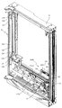
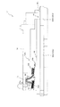
次いで、図5から図9を参照して、内枠12に対する遊技盤ユニット13の取付構造について説明する。上述したように、内枠12には、遊技盤ユニット13が正面側から着脱可能に配設される。この場合、内枠12における取付完了位置に遊技盤ユニット13が変位(配置)されることで、遊技盤ユニット13に設けられる遊技盤側コネクタ300Aと内枠12に設けられる内枠側コネクタ300Bとが接続される一方、内枠12における取付完了位置から遊技盤ユニット13が変位されるとで、遊技盤側コネクタ300Aと内枠側コネクタ300Bとの接続が解除される。   Next, with reference to FIGS. 5 to 9, the mounting structure of the game board unit 13 to the inner frame 12 will be described. As described above, the game board unit 13 is detachably disposed on the inner frame 12 from the front side. In this case, when the game board unit 13 is displaced (arranged) to the attachment completion position in the inner frame 12, the game board side connector 300A provided in the game board unit 13 and the inner frame side connector 300B provided in the inner frame 12 When the game board unit 13 is displaced from the attachment completion position in the inner frame 12, the connection between the game board side connector 300A and the inner frame side connector 300B is released.

まず、図5から図7を参照して、内枠12について説明する。図5は、遊技盤ユニット13が取り外された状態における内枠12の斜視図であり、図6は、遊技盤ユニット13が取り外された状態における内枠12の正面図である。   First, the inner frame 12 will be described with reference to FIGS. FIG. 5 is a perspective view of the inner frame 12 with the game board unit 13 removed, and FIG. 6 is a front view of the inner frame 12 with the game board unit 13 removed.

図5及び図6に示すように、内枠12は、遊技盤ユニット13(ベース板60)の周囲(端面)を囲む周壁部124と、その周壁部124から内枠12の内方へ向けて立設され遊技盤ユニット13におけるベース板60の背面に対向する背面板部125とからなる。周壁部124は、遊技盤ユニット13におけるベース板60の上下左右の各端面に対してそれぞれ対向する内壁面を有して形成され、全体として遊技盤ユニット13(ベース板60の端面)を囲む環状をなす。   As shown in FIG. 5 and FIG. 6, the inner frame 12 has a peripheral wall portion 124 that surrounds the periphery (end surface) of the game board unit 13 (base plate 60), and from the peripheral wall portion 124 toward the inside of the inner frame 12. The rear plate portion 125 is erected and faces the back surface of the base plate 60 in the game board unit 13. The peripheral wall portion 124 is formed to have an inner wall surface that is opposed to each of the upper, lower, left, and right end surfaces of the base plate 60 in the game board unit 13 and surrounds the game board unit 13 (end surface of the base plate 60) as a whole. Make.

内枠12の周壁部124のうちの正面視左側(図5及び図6左側)に位置する壁部(即ち、前扉枠14(図1参照)を回動可能に支持する側の壁部)には、遊技盤ユニット13(ベース板60)の前方(図5紙面手前左側)への変位を規制する複数(本実施形態では2個)のストッパ部126が上下に離間して配設される。各ストッパ部126は、周壁部124の内壁面から内枠12の内方へ向けて突出され、遊技盤ユニット13におけるベース板60の前面に当接される。また、各ストッパ部126は、周壁部124の内壁面の幅内に収まるように形成され、前扉枠14側となる前方への突出が規制される。   Of the peripheral wall portion 124 of the inner frame 12, the wall portion located on the left side in the front view (left side in FIGS. 5 and 6) (ie, the wall portion on the side that rotatably supports the front door frame 14 (see FIG. 1)). In this embodiment, a plurality (two in this embodiment) of stopper portions 126 for restricting the displacement of the game board unit 13 (base plate 60) toward the front side (the front left side in FIG. 5) are vertically spaced apart. . Each stopper portion 126 protrudes from the inner wall surface of the peripheral wall portion 124 toward the inner side of the inner frame 12, and comes into contact with the front surface of the base plate 60 in the game board unit 13. Moreover, each stopper part 126 is formed so that it may be settled in the width | variety of the inner wall face of the surrounding wall part 124, and the protrusion to the front which becomes the front door frame 14 side is controlled.

ストッパ部126は、遊技盤ユニット13の上端寄り及び下端寄りとなる位置に配置され、遊技盤ユニット13の変位を安定して規制することが可能とされる。この場合、遊技盤ユニット13の外レール62は、遊技盤ユニット13の回動基端側(図2の正面視左側)へ向けて凸となる正面視円弧状に湾曲されるところ(図2参照)、上端寄りのストッパ部126は外レール62の凸となる部分よりも上方に配置され、下端寄りのストッパ部126は外レール62の凸となる部分よりも下方に配置される。これにより、遊技盤ユニット13(ベース板60)の正面側であって外レール62の外方に形成されるデッドスペースを、各ストッパ部126の配置スペースとして利用できるので、ストッパ部126の配設に起因して外レール62の配置が圧迫されることを抑制し、その結果、遊技領域の大きさを最大限確保できる。   The stopper portion 126 is disposed at a position near the upper end and the lower end of the game board unit 13 so that the displacement of the game board unit 13 can be stably regulated. In this case, the outer rail 62 of the game board unit 13 is curved in an arc shape in front view that is convex toward the rotation base end side (left side in front view in FIG. 2) of the game board unit 13 (see FIG. 2). ), The stopper portion 126 near the upper end is disposed above the convex portion of the outer rail 62, and the stopper portion 126 near the lower end is disposed below the convex portion of the outer rail 62. As a result, the dead space formed on the front side of the game board unit 13 (base plate 60) and outside the outer rail 62 can be used as an arrangement space for each stopper portion 126. As a result, the placement of the outer rail 62 is suppressed from being pressed, and as a result, the size of the game area can be secured to the maximum.

また、内枠12の背面板部125には、各ストッパ部126に対応する位置に背面保持部127がそれぞれ配設される。各背面保持部127は、各ストッパ部126との間に所定間隔を隔てつつ、背面板部125の内壁面から内枠12の内方へ向けて突出され、遊技盤ユニット13におけるベース板60の背面に当接される。この場合、背面保持部127は、ストッパ部126に対応する位置(即ち、対面する位置)に配設されるので、これらストッパ部126及び背面保持部127の間で遊技盤ユニット13におけるベース板60を挟持して、その遊技盤ユニット13の変位を安定して規制することができる。   Further, a back surface holding portion 127 is disposed on the back plate portion 125 of the inner frame 12 at a position corresponding to each stopper portion 126. Each back support portion 127 protrudes from the inner wall surface of the back plate portion 125 toward the inside of the inner frame 12 while being spaced apart from each stopper portion 126, so that the base plate 60 of the game board unit 13 has the base plate 60. It abuts on the back. In this case, since the back surface holding portion 127 is disposed at a position corresponding to the stopper portion 126 (that is, a position facing the stopper portion 126), the base plate 60 in the game board unit 13 is interposed between the stopper portion 126 and the back surface holding portion 127. And the displacement of the game board unit 13 can be stably regulated.

このように、内枠12の周壁部124のうちの正面視左側(図5及び図6左側)に位置する壁部(即ち、前扉枠14(図1参照)を回動可能に支持する側の壁部)には、遊技盤ユニット13におけるベース板60の正面視左側(図2左側)の側部60aを挿入可能な挿入部128が、ストッパ部126と背面板部125及び背面保持部127との間に形成される。   As described above, the wall portion (that is, the front door frame 14 (see FIG. 1)) located on the left side (left side in FIGS. 5 and 6) of the peripheral wall portion 124 of the inner frame 12 is rotatably supported. Of the base board 60 in the game board unit 13, an insertion part 128 into which the side part 60 a on the left side (the left side in FIG. 2) can be inserted is a stopper part 126, a back plate part 125, and a back support part 127. Formed between.

挿入部128は、前扉枠14(図1参照)の回動先端側(図5紙面右手前側)が開放された形状に形成されることで、かかる挿入部128へ遊技盤ユニット13(ベース板60の側部60a)を前扉枠14の回動先端側から挿入可能とされる。即ち、前扉枠14を全開にできない場合であっても、前扉枠14を所定の角度だけ開放し、その開放側(前扉枠14の回動先端側)から内枠12の挿入部128へ遊技盤ユニット13(ベース板60の側部60a)を挿入することができる。   The insertion portion 128 is formed in a shape in which the front end side of the front door frame 14 (see FIG. 1) (the right front side in FIG. 5) is opened, so that the game board unit 13 (base plate) is connected to the insertion portion 128. 60 side part 60a) can be inserted from the front end side of the front door frame 14. That is, even when the front door frame 14 cannot be fully opened, the front door frame 14 is opened by a predetermined angle, and the insertion portion 128 of the inner frame 12 is opened from the open side (the rotation tip side of the front door frame 14). The game board unit 13 (side portion 60a of the base plate 60) can be inserted.

詳細には、ストッパ部126と背面板部125及び背面保持部127との間の対向間隔(隙間寸法)は、挿入部128の挿入奥側(周壁部124の内壁面側)では遊技盤ユニット13におけるベース板60の厚さ寸法と略同一に設定される一方、挿入手前側(挿入部128の入口部分側)では遊技盤ユニット13におけるベース板60の厚さ寸法よりも大きく設定される。これにより、遊技盤ユニット13(ベース板60)を挿入部128に対して斜め前方から挿入可能とすると共に、挿入部128に挿入された遊技盤ユニット13をその挿入部128を中心として回動可能とすることができる。   Specifically, the facing distance (gap size) between the stopper portion 126 and the back plate portion 125 and the back surface holding portion 127 is the gaming board unit 13 on the insertion back side of the insertion portion 128 (inner wall surface side of the peripheral wall portion 124). Is set to be substantially the same as the thickness dimension of the base plate 60, while the thickness is set to be larger than the thickness dimension of the base plate 60 in the game board unit 13 on the front side of the insertion (on the inlet portion side of the insertion portion 128). As a result, the game board unit 13 (base plate 60) can be inserted into the insertion portion 128 obliquely from the front, and the game board unit 13 inserted into the insertion portion 128 can be rotated around the insertion portion 128. It can be.

即ち、ストッパ部126は、その先端側において遊技盤ユニット13(ベース板60の側部60a)と対向する背面に面取りが施され、背面保持部127との間の対向間隔が先端側へ向かうほど大きくなるように傾斜されることで、挿入部128の入口部分が拡張される。これにより、挿入部128の入口部分において、ストッパ部126と背面保持部127との間の対向間隔(隙間寸法)を大きくし、遊技盤ユニット13を斜めに挿入する際のストッパ部126と遊技盤ユニット13(ベース板60の側部60a)との引っ掛かりを抑制できる。また、挿入部128の入口部分を斜め前方に向けることにより、遊技盤ユニット13の挿入時にその遊技盤ユニット13が前扉枠14の後方への張出部分や内枠12の右側部分(図5右側)等に干渉することを抑制できる。その結果、遊技盤ユニット13を内枠12に装着する際の作業性の向上を図ることができる。   That is, the stopper portion 126 is chamfered on the back surface facing the game board unit 13 (the side portion 60a of the base plate 60) on the front end side, and the facing distance between the back surface holding portion 127 and the front end side becomes closer to the front end side. The entrance portion of the insertion portion 128 is expanded by being inclined so as to increase. As a result, in the entrance portion of the insertion portion 128, the opposing space (gap size) between the stopper portion 126 and the back surface holding portion 127 is increased, and the stopper portion 126 and the game board when the game board unit 13 is inserted obliquely. It is possible to prevent the unit 13 (the side part 60a of the base plate 60) from being caught. Further, by directing the entrance portion of the insertion portion 128 obliquely forward, when the game board unit 13 is inserted, the game board unit 13 projects to the rear side of the front door frame 14 or the right side portion of the inner frame 12 (FIG. 5). Interference with the right side) and the like can be suppressed. As a result, workability when the game board unit 13 is mounted on the inner frame 12 can be improved.

挿入部128(ストッパ部126)の下方(詳細には、周壁部124のうちの遊技盤ユニット13(ベース板60の底面60b)に対向する壁部における回動基端側の端部)には、挿入部128に挿入された遊技盤ユニット13(ベース板60)の底面を仮置き可能な第1仮置き部129が設けられる。第1仮置き部129は、上方を向く平坦面として形成され、挿入部128の直下に配設されることで、遊技盤ユニット13(ベース板60)の底面60bのうちの回動基部側に位置する第1底面60b1(図8参照)を支持する。これにより、遊技盤ユニット13(ベース板60の側部60a)を挿入部128へ挿入する際の作業者の作業負担を減らすことができると共に、挿入後の遊技盤ユニット13の回動操作を容易とすることができる。   Below the insertion portion 128 (stopper portion 126) (specifically, the end portion on the rotation base end side of the wall portion of the peripheral wall portion 124 facing the game board unit 13 (the bottom surface 60b of the base plate 60)). A first temporary placement portion 129 capable of temporarily placing the bottom surface of the game board unit 13 (base plate 60) inserted into the insertion portion 128 is provided. The first temporary placement portion 129 is formed as a flat surface facing upward, and is disposed directly below the insertion portion 128 so that the first temporary placement portion 129 is disposed on the rotating base side of the bottom surface 60b of the game board unit 13 (base plate 60). The located first bottom surface 60b1 (see FIG. 8) is supported. Thereby, the work burden on the operator when inserting the game board unit 13 (the side part 60a of the base plate 60) into the insertion part 128 can be reduced, and the rotation operation of the game board unit 13 after the insertion can be easily performed. It can be.

第1仮置き部129の反対側(周壁部124のうちの遊技盤ユニット13(ベース板60の底面60b)に対向する壁部における回動先端側の端部)には、挿入部128に挿入された遊技盤ユニット13(ベース板60の底面60b)を仮置き可能な第2仮置き部702が設けられる(図7参照)。第2仮置き部702は、上方を向く平坦面として形成され、ベース板60の底面60bのうちの回動先端側に位置する第2底面60b2(図8参照)を支持する。   Inserted into the insertion portion 128 on the opposite side of the first temporary placement portion 129 (the end portion on the rotating tip side of the wall portion facing the game board unit 13 (the bottom surface 60b of the base plate 60) of the peripheral wall portion 124). A second temporary placement portion 702 is provided on which the placed game board unit 13 (the bottom surface 60b of the base plate 60) can be temporarily placed (see FIG. 7). The second temporary placement portion 702 is formed as a flat surface facing upward, and supports the second bottom surface 60b2 (see FIG. 8) located on the rotating front end side of the bottom surface 60b of the base plate 60.

第1仮置き部129は、第2仮置き部702に対し上方に位置し、これら第1仮置き部129及び第2仮置き部702の配置に対応して、遊技盤ユニット13におけるベース板60の底面60bは、第1底面60b1が第2底面60b2よりも上方に位置する階段状に形成される(図7参照)。遊技盤ユニット13におけるベース板60の側部60aを挿入部128に挿入し回動させる際には、第1仮置き部129に遊技盤ユニット13(ベース板60)の第1底面60b1が仮置き(一時的に載置)されることで、遊技盤ユニット13の重量の少なくとも一部を内枠12に支持させることができる。これにより、遊技盤ユニット13を装着する際の作業者の作業負担を減らすことができると共に、遊技盤ユニット13の回動操作を容易とすることができる。   The first temporary placement portion 129 is positioned above the second temporary placement portion 702, and the base plate 60 in the game board unit 13 corresponds to the arrangement of the first temporary placement portion 129 and the second temporary placement portion 702. The bottom surface 60b is formed in a step shape in which the first bottom surface 60b1 is located above the second bottom surface 60b2 (see FIG. 7). When the side portion 60a of the base plate 60 in the game board unit 13 is inserted into the insertion portion 128 and rotated, the first bottom surface 60b1 of the game board unit 13 (base plate 60) is temporarily placed in the first temporary placement portion 129. By being (temporarily placed), at least a part of the weight of the game board unit 13 can be supported by the inner frame 12. Thereby, while being able to reduce the work burden of the operator at the time of mounting | wearing the game board unit 13, the rotation operation of the game board unit 13 can be made easy.

一方、遊技盤ユニット13の回動動作における終期では、遊技盤ユニット13(ベース板60)の第2底面60b2が第2仮置き部702に仮置き(一時的に載置)されることで、内枠側コネクタ300B(第1メスコネクタ800及び第2メスコネクタ900)に対する遊技盤側コネクタ300A(第1オスコネクタ500及び第2オスコネクタ600)の高さ位置を位置決めすることができる。これにより、接続を開始する際に、両コネクタ300A,300Bが衝突して損傷することを抑制できると共に、接続を解除する際に、両コネクタ300A,300Bが無理な姿勢となり変形することで損傷を招くことを抑制できる。   On the other hand, in the final stage in the turning operation of the game board unit 13, the second bottom surface 60b2 of the game board unit 13 (base plate 60) is temporarily placed (temporarily placed) on the second temporary placement part 702. The height position of the game board side connector 300A (first male connector 500 and second male connector 600) relative to the inner frame side connector 300B (first female connector 800 and second female connector 900) can be positioned. Accordingly, when the connection is started, both the connectors 300A and 300B can be prevented from colliding and being damaged, and when the connection is released, the both connectors 300A and 300B are deformed into an unreasonable posture and damaged. Invitation can be suppressed.

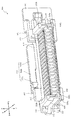
ここで、図7を参照して、内枠側コネクタ300Bについて説明する。図7は、内枠側コネクタ300Bの正面斜視図であり、内枠12から取り外された状態の内枠側コネクタ300Bが図示される。   Here, the inner frame side connector 300B will be described with reference to FIG. FIG. 7 is a front perspective view of the inner frame side connector 300 </ b> B, and shows the inner frame side connector 300 </ b> B removed from the inner frame 12.

図7に示すように、内枠側コネクタ300Bは、箱状に形成される台座700と、その台座700に固着されるコネクタ用基板(図示せず)と、そのコネクタ用基板に搭載される第1メスコネクタ800及び第2メスコネクタ900とを備える。コネクタ用基板は、一方の板面に第1メスコネクタ800及び第2メスコネクタ900が搭載されると共に、他方の板面が半田面とされ、一方の板面(搭載面)を遊技機正面側(遊技盤ユニット13側、図6紙面手前側)へ向けた姿勢で配設される。台座700には、上側部分に開口701が開口形成され、この台座700の開口701を介して、第1メスコネクタ800及び第2メスコネクタ900の接続口(受入口)が遊技機前方(遊技盤ユニット13側)に露出した状態とされる。これにより、内枠側コネクタ300Bは、遊技盤ユニット13の遊技盤側コネクタ300Aと接続可能とされる。   As shown in FIG. 7, the inner frame side connector 300 </ b> B includes a base 700 formed in a box shape, a connector board (not shown) fixed to the base 700, and a first board mounted on the connector board. 1 female connector 800 and 2nd female connector 900 are provided. In the connector board, the first female connector 800 and the second female connector 900 are mounted on one plate surface, the other plate surface is a solder surface, and one plate surface (mounting surface) is the front side of the gaming machine. It is arranged in a posture toward (the game board unit 13 side, the front side in FIG. 6). An opening 701 is formed in the upper portion of the pedestal 700, and the connection port (receiving port) of the first female connector 800 and the second female connector 900 is connected to the front of the gaming machine (game board) through the opening 701 of the pedestal 700. The unit 13 side is exposed. Accordingly, the inner frame side connector 300B can be connected to the game board side connector 300A of the game board unit 13.

第1メスコネクタ800及び第2メスコネクタ900は、一面側に接続口(受入口)を有する箱状のケース体810,910と、そのケース体810,910の上下の内壁面にそれぞれ幅方向(図6左右方向)に沿って等間隔に列設されると共に導電性材料からなる複数の接点部材820,920とを備える。   The first female connector 800 and the second female connector 900 have a box-like case body 810, 910 having a connection port (reception port) on one surface side, and an inner wall on the upper and lower sides of the case body 810, 910 in the width direction ( A plurality of contact members 820 and 920 made of a conductive material are provided at equal intervals along the horizontal direction of FIG.

第1メスコネクタ800及び第2メスコネクタ900は、その接続口(受入口)を遊技機斜め前方(内枠12に遊技盤ユニット13を取り付ける際の遊技盤ユニット13の回動先端側)へ向けた傾斜姿勢でそれぞれ配設される一方、それらの前後位置(図6紙面垂直方向位置)は略同一の位置に設定される。これにより、内枠12に対する遊技盤ユニット13の回動動作に伴う遊技盤側コネクタ300A及び内枠側コネクタ300Bの接続およびその解除をスムーズに行うことができると共に、両コネクタ300A,300Bに歪等が発生することを抑制でき、また、第1メスコネクタ800及び第2メスコネクタ900の配設に要するスペース(占有空間)が上下および左右に拡がることを抑制できる。   The first female connector 800 and the second female connector 900 have their connection ports (reception ports) directed obliquely forward of the gaming machine (the rotation tip side of the gaming board unit 13 when the gaming board unit 13 is attached to the inner frame 12). The front and rear positions (positions in the vertical direction in FIG. 6) are set to substantially the same positions. As a result, the game board side connector 300A and the inner frame side connector 300B can be smoothly connected to and released from the game board unit 13 with respect to the inner frame 12, and the connectors 300A and 300B are distorted. Can be suppressed, and the space (occupied space) required for disposing the first female connector 800 and the second female connector 900 can be prevented from expanding vertically and horizontally.

ケース体810,910には、幅方向に対向する左右の内壁面にガイド溝部830,930が凹設される。ガイド溝部830,930は、第1オスコネクタ500及び第2オスコネクタ600の被ガイド部530を受け入れる断面コ字状の凹溝であり、直線状に延設される2本が所定間隔を隔てつつ平行に並設される。また、ガイド溝830,930の開口端には、内方へ向けて下降傾斜する傾斜面(案内面830a,930a)が形成され、ケース体810,910の上下の内壁面における開口端には、内方へ向けて下降傾斜すると共に案内面830a,930aに連なる傾斜面(案内面810a,910a)が形成される。   In the case bodies 810 and 910, guide groove portions 830 and 930 are recessed in the left and right inner wall surfaces facing in the width direction. The guide groove portions 830 and 930 are U-shaped concave grooves that receive the guided portions 530 of the first male connector 500 and the second male connector 600, and two linearly extending grooves are spaced apart from each other by a predetermined interval. They are arranged in parallel. In addition, inclined surfaces (guide surfaces 830a, 930a) that are inclined downward inward are formed at the opening ends of the guide grooves 830, 930, and at the opening ends of the upper and lower inner wall surfaces of the case bodies 810, 910, Inclined surfaces (guide surfaces 810a and 910a) which are inclined downward inward and continue to the guide surfaces 830a and 930a are formed.

よって、接続初期においては、被ガイド部530の先端(案内面530a,530b)を案内面810a,830a,910a,930aによりガイド溝部830,930へ向けて案内可能として、接続初期における被ガイド部530とガイド溝部830,930との間の位置ズレを許容できる。被ガイド部530の先端がガイド溝部830,930へ挿入された後は、被ガイド部530がガイド溝830,930の延設方向に沿って嵌入されることで、第1メスコネクタ800及び第2メスコネクタ900に対する第1オスコネクタ500及び第2オスコネクタ600の傾斜を矯正でき、両者の接点部材520,820を適切な状態で接触させることができる。   Therefore, at the initial stage of connection, the leading ends (guide surfaces 530a and 530b) of the guided portion 530 can be guided toward the guide groove portions 830 and 930 by the guide surfaces 810a, 830a, 910a, and 930a, and the guided portion 530 at the initial stage of connection. And the guide groove portions 830 and 930 can be displaced. After the leading end of the guided portion 530 is inserted into the guide groove portions 830 and 930, the guided portion 530 is inserted along the extending direction of the guide grooves 830 and 930, whereby the first female connector 800 and the second female connector 800 are inserted. The inclination of the first male connector 500 and the second male connector 600 with respect to the female connector 900 can be corrected, and both contact members 520 and 820 can be brought into contact with each other in an appropriate state.

なお、ガイド溝部830,930は、並設される2本の溝幅寸法が互いに異なる寸法値に設定される。これにより、第1オスコネクタ500及び第2オスコネクタ600が正規の姿勢から上下反転された姿勢で第1メスコネクタ800及び第2メスコネクタ900に接続されることを規制することができる。   The guide groove portions 830 and 930 are set to different dimension values for the two groove width dimensions provided side by side. Thereby, it can be controlled that the 1st male connector 500 and the 2nd male connector 600 are connected to the 1st female connector 800 and the 2nd female connector 900 in the posture turned upside down from the normal posture.

台座700の前面には、上述した第2仮置き部702が形成される。第2仮置き部702は、台座700の横幅に対して、その一部に部分的に形成されると共に、内枠12に遊技盤ユニット13を取り付ける際の遊技盤ユニット13の回動先端側(図5及び図6右側)に配設される。これにより、第1仮置き部129と第2仮置き部702との間の距離を大きくして、遊技盤ユニット13の安定した支持を可能としつつ、第2仮置き部702の占有空間を抑制でき、その分、第2仮置き部702の非形成領域を利用して、台座700の前面に他の部材を配設することができる。   The above-described second temporary placement portion 702 is formed on the front surface of the base 700. The second temporary placement portion 702 is partially formed with respect to the lateral width of the pedestal 700 and at the front end of the game board unit 13 when the game board unit 13 is attached to the inner frame 12 ( 5 and FIG. 6 right side). This increases the distance between the first temporary placement portion 129 and the second temporary placement portion 702, and enables stable support of the game board unit 13, while suppressing the occupied space of the second temporary placement portion 702. Accordingly, another member can be disposed on the front surface of the base 700 by using the non-formation region of the second temporary placement portion 702.

仮置き部702は、上述したように、遊技盤ユニット13の底面60(第2底面60b2)が載置可能に形成され、その遊技盤ユニット13を内枠12における取付完了位置へ変位させる際の案内面として機能する。即ち、遊技盤ユニット13を仮置き部702に載置した上でその仮置き部702に沿ってスライドさせることができる。これにより、比較的重量の嵩む遊技盤ユニット13を、内枠12における取付完了位置へ向けて正確に変位させやすくできるので、遊技盤側コネクタ300A及び内枠側コネクタ300Bの接続を開始する際に、これら両コネクタ300A,300Bどうしが衝突して破損することを抑制できる。また、遊技盤側コネクタ300A及び内枠側コネクタ300Bの接続が開始された後やその接続を解除する際には、遊技盤ユニット13を内枠12に対して一定の姿勢で変位させやすくすることができるので、遊技盤側コネクタ300A及び内枠側コネクタ300Bの間に無理な力が作用して破損することを抑制できる。   As described above, the temporary placement portion 702 is formed so that the bottom surface 60 (second bottom surface 60b2) of the game board unit 13 can be placed, and when the game board unit 13 is displaced to the mounting completion position in the inner frame 12. It functions as a guide surface. That is, the game board unit 13 can be slid along the temporary placement portion 702 after being placed on the temporary placement portion 702. This makes it easy to accurately displace the relatively heavy game board unit 13 toward the attachment completion position in the inner frame 12, so that when the connection of the game board side connector 300A and the inner frame side connector 300B is started. These connectors 300A and 300B can be prevented from colliding and being damaged. Further, after the connection of the game board side connector 300A and the inner frame side connector 300B is started or when the connection is released, the game board unit 13 is easily displaced with respect to the inner frame 12 in a fixed posture. Therefore, it is possible to suppress damage caused by an excessive force acting between the game board side connector 300A and the inner frame side connector 300B.

なお、第2仮置き部702が台座700の前面へ向けて張り出す張り出し寸法は、その第2仮置き部702に遊技盤ユニット13の底面60b(第2底面60b2)が載置され、かつ、遊技盤側コネクタ300A及び内枠側コネクタ300Bの接続が解除された状態を形成可能な長さ寸法に設定される。よって、先に遊技盤ユニット13の底面60bを第2仮置き部702に載置し、その後、遊技盤ユニット13を第2仮置き部702に沿ってスライドさせ、遊技盤側コネクタ300A及び内枠側コネクタ300Bの接続を行うことができる。また、遊技盤側コネクタ300A及び内枠側コネクタ300Bの接続の解除が完了された際に、遊技盤ユニット13を第2仮置き部702に載置された状態で保持することができる。その結果、比較的重い遊技盤ユニット13の内枠12への取り付け及び取り外しの作業と、遊技盤側コネクタ300A及び内枠側コネクタ300Bの接続および解除との作業性の向上を図ることができる。   The projecting dimension of the second temporary placement portion 702 projecting toward the front surface of the base 700 is such that the bottom surface 60b (second bottom surface 60b2) of the game board unit 13 is placed on the second temporary placement portion 702, and The length is set such that a state in which the connection of the game board side connector 300A and the inner frame side connector 300B is released can be formed. Therefore, the bottom surface 60b of the game board unit 13 is first placed on the second temporary placement part 702, and then the game board unit 13 is slid along the second temporary placement part 702, and the game board side connector 300A and the inner frame The side connector 300B can be connected. Further, when the connection between the game board side connector 300A and the inner frame side connector 300B is completed, the game board unit 13 can be held in a state of being placed on the second temporary placement portion 702. As a result, it is possible to improve workability of attaching and removing the relatively heavy game board unit 13 to the inner frame 12 and connecting and releasing the game board side connector 300A and the inner frame side connector 300B.

ここで、パチンコ機10は、遊技球の遊技領域でのスムーズな転動(流下)を考慮して、上端側を後方(背面側)へ位置させる傾斜姿勢(後方へ傾斜した姿勢)で設置される。この場合、第2仮置き部702は、パチンコ機10が設置された状態において水平な平坦面となるように、台座700の前面(遊技機前方)へ向けて下降傾斜する平坦面として形成される。この場合、パチンコ機10が設置された状態において、内枠12における取付完了位置へ向けて遊技盤ユニット13を変位させる際に、その取付完了位置へ向けて第2仮置き部702が下降傾斜されると、遊技盤ユニット13を回動操作する際に不用意に勢いがついて、両コネクタ300A,300Bを接続する際の衝撃が大きくなる一方、取付完了位置へ向けて第2仮置き部702が上昇傾斜されると、遊技盤ユニット13を回動操作する作業者の負荷が大きくなるところ、本字実施形態では、第2仮置き部702が水平とされることで、接続時の衝撃発生の抑制と作業者の負荷低減との両立を図ることができる。   Here, the pachinko machine 10 is installed in an inclined posture (post-tilt posture) in which the upper end side is positioned rearward (back side) in consideration of smooth rolling (downflow) in the game area of the game ball. The In this case, the second temporary placement portion 702 is formed as a flat surface that is inclined downward toward the front surface of the base 700 (front of the gaming machine) so as to be a horizontal flat surface in a state where the pachinko machine 10 is installed. . In this case, in the state where the pachinko machine 10 is installed, when the game board unit 13 is displaced toward the attachment completion position in the inner frame 12, the second temporary placement portion 702 is inclined downward toward the attachment completion position. Then, when the game board unit 13 is rotated, the momentum is inadvertently increased, and the impact when the connectors 300A and 300B are connected is increased. On the other hand, the second temporary placement portion 702 is directed toward the attachment completion position. When it is tilted upward, the load on the operator who rotates the game board unit 13 increases. In this embodiment, the second temporary placement portion 702 is leveled to generate an impact at the time of connection. It is possible to achieve both suppression and reduction of the load on the operator.

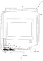
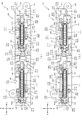
次いで、図8及び図9を参照して、遊技盤ユニット13について説明する。図8は、遊技盤ユニット13の背面図であり、図9は、図8の矢印IX方向視における遊技盤ユニット13の底面図である。   Next, the game board unit 13 will be described with reference to FIGS. 8 is a rear view of the game board unit 13, and FIG. 9 is a bottom view of the game board unit 13 as viewed in the direction of the arrow IX in FIG.

図8及び図9に示すように、遊技盤ユニット13は、樹脂材料から形成されるカバー部材74がベース板60の背面に配設され、ベース板60の背面に配設される各種構造部品や電気部品がカバー部材74の内部空間に収容される。カバー部材74は、背面視において、ベース板60の外形よりも小さな外形に設定され、ベース板60の側部60aがカバー部材74の外縁よりも突出される。これにより、遊技盤ユニット13を内枠12に取り付ける際には、内枠12の挿入部128(ストッパ部126と背面板部125及び背面保持部127との間)にベース板60の側部60aが挿入可能とされる。   As shown in FIGS. 8 and 9, the game board unit 13 includes a cover member 74 formed of a resin material disposed on the back surface of the base plate 60, and various structural components disposed on the back surface of the base plate 60. An electrical component is accommodated in the internal space of the cover member 74. The cover member 74 is set to an outer shape smaller than the outer shape of the base plate 60 in the rear view, and the side portion 60 a of the base plate 60 protrudes from the outer edge of the cover member 74. Thereby, when the game board unit 13 is attached to the inner frame 12, the side portion 60a of the base plate 60 is inserted into the insertion portion 128 (between the stopper portion 126, the rear plate portion 125, and the rear surface holding portion 127) of the inner frame 12. Can be inserted.

また、ベース板60の背面のうちの取付面BEには、遊技盤側コネクタ300Aが配設される。遊技盤側コネクタ300Aは、上述したように、内枠12における取付完了位置へ遊技盤ユニット13が変位されることで、内枠12の内枠側コネクタ300Bに接続されると共に、内枠12における取付完了位置から遊技盤ユニット13が変位されることで、内枠12の内枠側コネクタ300Bとの接続が解除されるものであり、カバー部材74の下方(図8下側)であって、側部60aと反対側(即ち、内枠12へ遊技盤ユニット13を取り付ける際の回動先端側、図8左側)となる端部に配設される。   Further, a game board side connector 300 </ b> A is disposed on the mounting surface BE on the back surface of the base plate 60. As described above, the game board side connector 300 </ b> A is connected to the inner frame side connector 300 </ b> B of the inner frame 12 by displacing the game board unit 13 to the attachment completion position in the inner frame 12. When the game board unit 13 is displaced from the attachment completion position, the connection with the inner frame side connector 300B of the inner frame 12 is released, and below the cover member 74 (lower side in FIG. 8), It is disposed at an end portion which is the side opposite to the side portion 60a (that is, the rotating front end side when attaching the game board unit 13 to the inner frame 12, the left side in FIG. 8).

遊技盤側コネクタ300Aは、箱状に形成される台座400と、その台座400に遊動可能な状態(接続の方向に直交する方向(矢印R−L及び矢印U−Dの方向、図10及び図11参照)への変位が許容された状態)で装着される第1オスコネクタ500及び第2オスコネクタ600とを備える。   The game board side connector 300A includes a pedestal 400 formed in a box shape and a state in which the pedestal 400 can move freely (directions orthogonal to the direction of connection (directions of arrows RL and UD, FIG. 10 and FIG. 10). 11), the first male connector 500 and the second male connector 600 are mounted.

台座400は、ベース板60の幅方向(図8左右方向)において側部60aと反対側の端部(遊技盤ユニット13の回動先端側、図8左側)に配設される。台座400には、第1開口421及び第2開口422が開口形成され、第1オスコネクタ500及び第2オスコネクタ600は、この台座400の第1開口421及び第2開口422を介して、遊技機後方(内枠12側)へ突出される。これにより、内枠12に対し遊技盤ユニット13を回動させる(取付完了位置へ変位させる)ことで、第1オスコネクタ500及び第2オスコネクタ600の先端側が第1メスコネクタ800及び第2メスコネクタ900の接続口(受入口)にそれぞれ挿入され、遊技盤側コネクタ300Aは、内枠12の内枠側コネクタ300Bと接続可能とされる。   The pedestal 400 is disposed at the end opposite to the side 60a in the width direction of the base plate 60 (the left-right direction in FIG. 8) (the rotation tip side of the game board unit 13, the left side in FIG. 8). A first opening 421 and a second opening 422 are formed in the pedestal 400, and the first male connector 500 and the second male connector 600 are played through the first opening 421 and the second opening 422 of the pedestal 400. It protrudes to the rear of the machine (inner frame 12 side). Thereby, the game board unit 13 is rotated with respect to the inner frame 12 (displaced to the attachment completion position), so that the first female connector 500 and the second male connector 600 have the first female connector 800 and the second female connector on the distal end side. The game board side connector 300 </ b> A is inserted into the connection port (receiving port) of the connector 900, and can be connected to the inner frame side connector 300 </ b> B of the inner frame 12.

第1オスコネクタ500及び第2オスコネクタ600は、遊技機斜め後方(内枠12に遊技盤ユニット13を取り付ける際の遊技盤ユニット13の回動基端側、図9右上側)へ向けた傾斜姿勢でそれぞれ配設される一方、それらの前後位置(図9上下方向位置)は略同一の位置に設定される。これにより、内枠12に対する遊技盤ユニット13の回動動作に伴う遊技盤側コネクタ300A及び内枠側コネクタ300Bの接続およびその解除をスムーズに行うことができると共に、両コネクタ300A,300Bに歪等が発生することを抑制でき、また、第1オスコネクタ500及び第2オスコネクタ600の配設に要するスペース(占有空間)が上下および左右に拡がることを抑制できる。   The first male connector 500 and the second male connector 600 are inclined toward the game machine diagonally backward (the rotation base end side of the game board unit 13 when attaching the game board unit 13 to the inner frame 12, the upper right side in FIG. 9). While being arranged in the posture, their front and rear positions (up and down direction positions in FIG. 9) are set to substantially the same position. As a result, the game board side connector 300A and the inner frame side connector 300B can be smoothly connected to and released from the game board unit 13 with respect to the inner frame 12, and the connectors 300A and 300B are distorted. Can be suppressed, and the space (occupied space) required for disposing the first male connector 500 and the second male connector 600 can be prevented from expanding vertically and horizontally.

ベース板60の背面には、配線保持部材75が配設される。配線保持部材75は、第1オスコネクタ500及び第2オスコネクタ600の電気的接続線WHを保持するための部材であり、遊技盤側コネクタ300Aの上方(図8上側)であって、遊技盤側コネクタ300Aよりもベース板60の背面側(図9上側)へ突出する位置に配設される。
A wiring holding member 75 is disposed on the back surface of the base plate 60. The wiring holding member 75 is a member for holding the electrical connection line WH of the first male connector 500 and the second male connector 600, and is above the game board side connector 300A (upper side in FIG. 8). It is disposed at a position protruding from the side connector 300A toward the back side (upper side in FIG. 9) of the base plate 60.

配線保持部材75の底面(遊技盤側コネクタ300A側の面、図8下側の面)には、開口75aが正面視横長の矩形状の開口として形成され、その開口75aに第1オスコネクタ500及び第2オスコネクタ600の電気的接続線WHが挿通される。電気的接続線WHは、開口75aの内周面に当接されることで保持される。これにより、電気的接続線WHを拘束して、第1オスコネクタ500及び第2オスコネクタ600までの電気的接続線WHの長さを一定に保つことができる。
An opening 75a is formed in the bottom surface of the wiring holding member 75 (the surface on the game board side connector 300A side, the lower surface in FIG. 8) as a rectangular opening that is horizontally long when viewed from the front, and the first male connector 500 is formed in the opening 75a. And the electrical connection line WH of the second male connector 600 is inserted. The electrical connection line WH is held by being brought into contact with the inner peripheral surface of the opening 75a. Thereby, the electrical connection line WH can be restrained and the length of the electrical connection line WH up to the first male connector 500 and the second male connector 600 can be kept constant.

ベース板60は、上述したように、その底面60bが段差を有する階段状に形成される。詳細には、底面60bは、側部60a側(遊技盤ユニット13の回動先端側)に配設される第1底面60b1とその第1底面60b1に連設されると共に遊技盤側コネクタ300A側(遊技盤ユニット13の回動基端側)に配設される第2底面60b2とからなり、第1底面60b1が第2底面60b2よりも上方(図8上側)に配置される。遊技盤ユニット13(ベース板60の側部60a)を内枠12の挿入部128(図5参照)に挿入し回動させる際には、先に、底面60bのうちの第1底面60b1が第1仮置き部129(図5参照)に仮置きされ、その状態から遊技盤ユニット13の回動(取付完了位置への変位)が更に進行されると、次いで、底面60bのうちの第2底面60b2が第2仮置き部702(図7参照)に仮置きされ、その後、遊技盤側コネクタ300Aと内枠12の内枠側コネクタ300Bとの接続が開始される。   As described above, the base plate 60 is formed in a staircase shape whose bottom surface 60b has a step. Specifically, the bottom surface 60b is connected to the first bottom surface 60b1 and the first bottom surface 60b1 disposed on the side portion 60a side (the rotation front end side of the game board unit 13) and the game board side connector 300A side. It consists of a second bottom surface 60b2 disposed on the rotation base end side of the game board unit 13, and the first bottom surface 60b1 is arranged above the second bottom surface 60b2 (upper side in FIG. 8). When the game board unit 13 (the side portion 60a of the base plate 60) is inserted into the insertion portion 128 (see FIG. 5) of the inner frame 12 and rotated, the first bottom surface 60b1 of the bottom surface 60b is first connected to the first bottom surface 60b1. When the game board unit 13 is temporarily placed in the temporary placement section 129 (see FIG. 5) and the game board unit 13 is further rotated (displaced to the attachment completion position), the second bottom face of the bottom face 60b is then placed. 60b2 is temporarily placed in the second temporary placement portion 702 (see FIG. 7), and then the connection between the game board side connector 300A and the inner frame side connector 300B of the inner frame 12 is started.

この場合、本実施形態では、ベース板60の底面60bにおいて、第1底面60b1と第2底面60b2との間の高低差(図8上下方向における高さ位置の差)は、内枠12における第1仮置き部129と第2仮置き部702との間の高低差(図6上下方向における高さ位置の差)よりも大きく設定される。そのため、第1底面60b1が第1仮置き部129に仮置きされた状態から遊技盤ユニット13の回動(取付完了位置への変位)が更に進行されると、第2底面60b2が第2仮置き部702に乗り上げた状態となり、これに伴って、第1底面60b1が第1仮置き部129から離間される。   In this case, in this embodiment, in the bottom surface 60b of the base plate 60, the height difference between the first bottom surface 60b1 and the second bottom surface 60b2 (the difference in height position in the vertical direction in FIG. 8) is The height difference between the first temporary placement portion 129 and the second temporary placement portion 702 (a difference in height position in the vertical direction in FIG. 6) is set. Therefore, when the rotation (displacement to the attachment completion position) of the game board unit 13 further proceeds from the state where the first bottom surface 60b1 is temporarily placed on the first temporary placement portion 129, the second bottom surface 60b2 becomes the second temporary surface. As a result, the first bottom surface 60b1 is separated from the first temporary placement portion 129.

即ち、内枠12の内枠側コネクタ300bにおける前方(正面)において、ベース板60の第2底面60b2と第2仮置き部702との接触が確保された後に、遊技盤ユニット13の遊技盤側コネクタ300Aと内枠12の内枠側コネクタ300Bとの接続を開始させることができる。よって、第1仮置き部129と第1底面60b1との間の関係(寸法公差)に影響を受けず、第2仮置き部702と第2底面60b2との間の関係(寸法公差)のみで両コネクタ300A,300Bの高さ位置を規定することができる。その結果、両コネクタ300A,300Bの接続が開始される際に、少なくとも遊技盤ユニット13(ベース板60)の回動先端側の内枠12に対する高さ方向位置(上下位置)のばらつきを抑制することができるので、その分、両コネクタ300A,300Bの接続を円滑に開始させることができる。   That is, in the front (front side) of the inner frame side connector 300b of the inner frame 12, after the contact between the second bottom surface 60b2 of the base plate 60 and the second temporary placement portion 702 is ensured, the game board side of the game board unit 13 is secured. The connection between the connector 300A and the inner frame side connector 300B of the inner frame 12 can be started. Therefore, the relationship (dimension tolerance) between the first temporary placement portion 129 and the first bottom surface 60b1 is not affected, and only the relationship (dimension tolerance) between the second temporary placement portion 702 and the second bottom surface 60b2. The height positions of both connectors 300A and 300B can be defined. As a result, when the connection of both the connectors 300A and 300B is started, at least variations in the height direction position (vertical position) of the game board unit 13 (base plate 60) with respect to the inner frame 12 on the rotating front end side are suppressed. Therefore, the connection of both the connectors 300A and 300B can be started smoothly accordingly.

次いで、図10から図24を参照して、遊技盤側コネクタ300Aの詳細構成について説明する。図10は、遊技盤側コネクタ300Aの正面斜視図である。また、図11(a)は、遊技盤側コネクタ300Aの正面図であり、図11(b)は、図11(a)の矢印XIb方向視における遊技盤側コネクタ300Aの側面図である。   Next, a detailed configuration of the game board side connector 300A will be described with reference to FIGS. FIG. 10 is a front perspective view of the game board side connector 300A. FIG. 11 (a) is a front view of the game board side connector 300A, and FIG. 11 (b) is a side view of the game board side connector 300A as viewed in the direction of the arrow XIb in FIG. 11 (a).

なお、図10及び図11において、矢印R−L、矢印U−D及び矢印L−Rは、互いに直交する方向を示しており、矢印R−Lは、台座400の第1正面板411及び第2正面板412に平行で且つ台座400の長手方向に平行な方向を示し、矢印U−Dは、台座400の第1正面板411及び第2正面板412に平行で且つ台座400の短手方向に平行な方向を示し、矢印F−Bは、台座400の第1正面板411及び第2正面板412に垂直な方向を示す。図12以降の各図においても同様であるので、その説明は省略する。   10 and 11, arrows RL, arrows UD, and LR indicate directions orthogonal to each other, and arrows RL indicate the first front plate 411 and the first of the base 400. 2 indicates a direction parallel to the front plate 412 and parallel to the longitudinal direction of the pedestal 400, and an arrow UD is parallel to the first front plate 411 and the second front plate 412 of the pedestal 400 and the short direction of the pedestal 400 The arrow FB indicates a direction perpendicular to the first front plate 411 and the second front plate 412 of the pedestal 400. This is the same in each figure after FIG. 12, and the description thereof will be omitted.

図10及び図11に示すように、遊技盤側コネクタ300Aは、箱状に形成される台座400と、その台座400に保持される第1オスコネクタ500及び第2オスコネクタ600とを備える。台座400は、第1正面板411及び第2正面板412の第1開口421及び第2開口422に第1オスコネクタ500及び第2オスコネクタ600をそれぞれ挿通させることで、上述したように、第1オスコネクタ500及び第2オスコネクタ600を接続の方向(矢印F−B方向)に直交する方向(矢印R−L方向又は矢印U−D方向)に変位可能に保持する。ここで、図12から図14を参照して、台座400の詳細構成について説明する。   As shown in FIGS. 10 and 11, the game board side connector 300 </ b> A includes a pedestal 400 formed in a box shape, and a first male connector 500 and a second male connector 600 held on the pedestal 400. As described above, the pedestal 400 allows the first male connector 500 and the second male connector 600 to be inserted through the first opening 421 and the second opening 422 of the first front plate 411 and the second front plate 412, respectively. The first male connector 500 and the second male connector 600 are held displaceably in a direction (arrow RL direction or arrow UD direction) orthogonal to the direction of connection (arrow FB direction). Here, the detailed configuration of the base 400 will be described with reference to FIGS.

図12は、台座400の正面斜視図であり、図13(a)は、台座400の正面図であり、図13(b)は、図13(a)の矢印XIIIb方向視における台座400の側面図である。また、図14(a)は、図13(a)のXIVa−XIVa線における台座400の断面図であり、図14(b)は、図13(a)のXIVb−XIVb線における台座400の断面図である。なお、図13(b)、図14(a)及び図14(b)では、遊技機ユニット13の背面であって遊技盤側コネクタ300Aが取り付けられる取付面BEが二点鎖線を用いて模式的図に図示される。   12 is a front perspective view of the pedestal 400, FIG. 13 (a) is a front view of the pedestal 400, and FIG. 13 (b) is a side view of the pedestal 400 in the direction of arrow XIIIb in FIG. 13 (a). FIG. 14A is a cross-sectional view of the pedestal 400 taken along line XIVa-XIVa of FIG. 13A, and FIG. 14B is a cross-sectional view of the pedestal 400 taken along line XIVb-XIVb of FIG. FIG. In FIG. 13B, FIG. 14A, and FIG. 14B, a mounting surface BE, which is the back surface of the gaming machine unit 13 and to which the gaming board side connector 300A is attached, is schematically shown using a two-dot chain line. Illustrated in the figure.

図12から図14に示すように、台座400は、遊技盤ユニット13(図8及び図9参照)の背面に所定間隔を隔てて対向配置される平板状の第1正面板411及び第2正面板412と、それら第1正面板411及び第2正面板412の間を接続する接続板413と、第1正面板411及び第2正面板412の正面視矩形の4辺のうちの互いに対向する短辺(図13(a)の右側および左側の辺)にそれぞれ接続される短手側壁414,415及び4辺のうちの互いに対向する長辺(図13(a)の上側および下側の辺)にそれぞれ接続される長手側壁416,417と、を備え、これら各部位が樹脂材料から一体に形成されることで、背面側(図14(a)及び図14(b)の下側)が開放された箱状に形成される。
As shown in FIGS. 12 to 14, the pedestal 400 includes a flat plate-like first front plate 411 and a second main plate that are opposed to the back surface of the game board unit 13 (see FIGS. 8 and 9) at a predetermined interval. The face plate 412, the connection plate 413 that connects the first front plate 411 and the second front plate 412, and the four sides of the first front plate 411 and the second front plate 412 that are rectangular in front view are opposed to each other. Of the short side walls 414, 415, and 4 sides connected to the short side (the right side and the left side in FIG. 13A), the long sides facing each other (the upper and lower sides of FIG. 13A) ) And long side wall plates 416 and 417 respectively connected to each other, and these portions are integrally formed from a resin material, so that the back side (the lower side of FIGS. 14A and 14B) Is formed in an open box shape.

第1正面板411、第2正面板412、接続板413、短手側壁414,415及び長手側壁416,417は、互いに同一の板厚寸法に設定されると共に、これらの板厚寸法は、後述する第1基端側弾性片441などの各弾性片441,451,442,452の板厚寸法よりも大きくされる。このように、台座400の外殻を形成する部位の板厚寸法を全体に同一の板厚寸法に設定すると共に、基端が固定され先端が自由端となる片持ち片として形成される各弾性片441,451,442,452と外殻を形成する部位との間に板厚寸法の差を設けることで、成型金型内での素材の流動性が悪化しやすい各弾性片441,451,442,452における成型性を確保して、成型時の歩留まりの向上を図りつつ、外殻の剛性を確保して、各弾性片441,451,442,452や第1及び第2オスコネクタ500,600の弾性変形や変位を安定して保持することができる。
The first front plate 411, the second front plate 412, the connection plate 413, the short side walls 414, 415 and the long side wall plates 416, 417 are set to the same plate thickness dimension, and these plate thickness dimensions are: It is made larger than the plate thickness dimension of each elastic piece 441, 451, 442, 452 such as a first base end side elastic piece 441 described later. In this way, the plate thickness dimension of the portion forming the outer shell of the base 400 is set to the same plate thickness dimension as a whole, and each elastic member is formed as a cantilever piece whose base end is fixed and whose distal end is a free end. By providing a difference in plate thickness between the pieces 441, 451, 442, 452 and the portion forming the outer shell, the elastic pieces 441, 451, which tend to deteriorate the fluidity of the material in the molding die, are provided. Each of the elastic pieces 441, 451, 442, 452, the first and second male connectors 500, and the rigidity of the outer shell is secured while ensuring the moldability at 442, 452 and improving the yield during molding. 600 elastic deformation and displacement can be stably held.

第1正面板411及び第2正面板412は、矢印F−B方向に位置を異ならせつつ互いに平行に配設される。詳細には、第1正面板411及び第2正面板412は、台座400が遊技盤ユニット13の取付面BEに取り付けられた状態では(図9参照)、ベース板60の側部60aへ向けて下降傾斜される一方、遊技盤ユニット13における前後位置(図14(a)及び図14(b)の上下方向位置)が略同一の位置となるように形成される。これにより、上述したように、第1オスコネクタ500及び第2オスコネクタ600を、遊技機斜め後方へ向けた傾斜姿勢でそれぞれ配設すると共に、それらの前後位置を略同一の位置に設定できる(図9参照)。   The first front plate 411 and the second front plate 412 are arranged in parallel to each other while being different in position in the direction of the arrow FB. Specifically, the first front plate 411 and the second front plate 412 are directed toward the side portion 60a of the base plate 60 when the pedestal 400 is attached to the attachment surface BE of the game board unit 13 (see FIG. 9). While being inclined downward, the front and rear positions (the vertical positions in FIGS. 14A and 14B) of the game board unit 13 are formed to be substantially the same position. Thereby, as above-mentioned, while arrange | positioning the 1st male connector 500 and the 2nd male connector 600 in the inclination attitude | position toward the game machine diagonally back, those front-back positions can be set to the substantially the same position ( (See FIG. 9).

第1正面板411には、第1開口421が開口形成される。第1開口421は、第1オスコネクタ500を挿通するための開口であり(図10参照)、正面視横長の矩形状に形成される中央開口421aの外縁に正面視横長の矩形状に形成される一対の基端側開口421b及び一対の先端側開口421cがそれぞれ連なることで1の開口として形状とされる。これにより、第1正面板411には、基端が長手側壁板416,417側に保持されると共に先端が第1開口421内に突出される一対の中間正面板411aと、基端が長手側壁板416,417及び短手側壁板414側に保持されると共に先端が第1開口421内に突出される一対の基端側正面板411b及び一対の先端側正面板411cとが形成される。   A first opening 421 is formed in the first front plate 411. The first opening 421 is an opening through which the first male connector 500 is inserted (see FIG. 10), and is formed in a rectangular shape that is horizontally long when viewed from the front at the outer edge of the central opening 421a that is horizontally long when viewed from the front. A pair of base-end openings 421b and a pair of tip-end openings 421c are connected to form a single opening. Accordingly, the first front plate 411 has a pair of intermediate front plates 411a whose proximal ends are held on the long side wall plates 416 and 417 and whose front ends protrude into the first opening 421, and the base ends are long side walls. A pair of proximal-side front plates 411b and a pair of distal-side front plates 411c, which are held on the plates 416, 417 and the short side wall plate 414 side and whose tips protrude into the first opening 421, are formed.

第2正面板412には、第2開口422が開口形成される。第2開口422は、第2オスコネクタ600を挿通するための開口であり(図10参照)、正面視横長の矩形状に形成される中央開口422aの外縁に正面視横長の矩形状に形成される一対の基端側開口422b及び一対の先端側開口422cがそれぞれ連なることで1の開口として形状とされる。これにより、第2正面板412には、基端が長手側壁板416,417側に保持されると共に先端が第2開口421内に突出される一対の中間正面板412aと、基端が長手側壁板416,417及び短手側壁板415側に保持されると共に先端が第2開口422内に突出される一対の基端側正面板412b及び一対の先端側正面板412cとが形成される。   A second opening 422 is formed in the second front plate 412. The second opening 422 is an opening through which the second male connector 600 is inserted (see FIG. 10), and is formed in a rectangular shape that is horizontally long when viewed from the front at the outer edge of the central opening 422a that is horizontally long when viewed from the front. A pair of proximal end openings 422b and a pair of distal end openings 422c are connected to form a single opening. Thus, the second front plate 412 has a pair of intermediate front plates 412a whose proximal ends are held on the long side wall plates 416 and 417 and whose front ends protrude into the second opening 421, and the base ends are long side walls. A pair of proximal-side front plates 412b and a pair of distal-side front plates 412c, which are held on the plates 416, 417 and the short side wall plate 415 side and whose tips protrude into the second opening 422, are formed.

ここで、第2正面板412は、中間正面板412aの矢印R−L方向における長さ寸法が、第1正面板411における中間正面板411aの矢印R−L方向における長さ寸法よりも長くされる点を除き、第1正面板411と略同一に構成される。よって、これに伴い、第2開口422についても、中央開口422aの矢印R−L方向における長さ寸法が、第1開口421における中央開口421aの矢印R−L方向における長さ寸法よりも長くされる点を除き、第1開口421と略同一に構成される。   Here, in the second front plate 412, the length dimension in the arrow RL direction of the intermediate front plate 412a is longer than the length dimension in the arrow RL direction of the intermediate front plate 411a in the first front plate 411. The first front plate 411 is configured substantially the same except for the above. Accordingly, the length of the second opening 422 in the direction of the arrow RL of the central opening 422a is also made longer than the length of the central opening 421a of the first opening 421 in the direction of arrow RL. Except for this point, the first opening 421 is configured substantially the same.

第1正面板411及び第2正面板412の中間正面板411a,412aには、基端側開口421b,422bに接する外縁であってその外縁の正面(図14(a)及び図14(b)の上側)に、基端側開口421b,422bへ向かうに従って下降傾斜する傾斜面411a1,412a1が形成される。これにより、後述するように、第1オスコネクタ500及び第2オスコネクタ600を台座400に組み付ける際の作業性の向上を図ることができる。   The intermediate front plates 411a and 412a of the first front plate 411 and the second front plate 412 are outer edges that are in contact with the base end openings 421b and 422b, and are front surfaces of the outer edges (FIGS. 14A and 14B). Are inclined surfaces 411a1 and 412a1 that are inclined downward toward the base end openings 421b and 422b. Thereby, the workability | operativity at the time of assembling | attaching the 1st male connector 500 and the 2nd male connector 600 to the base 400 can be aimed at so that it may mention later.

但し、第1正面板411の中間正面板411aに対し、傾斜面411a1の形成を省略しても良い。上述したように、第1開口421は、第2開口422に対し、矢印R−L方向における長さ寸法が短くされるので、基端側開口421b及び先端側開口421cの離間距離も短くされ、その分、傾斜面411a1が省略されたとしても、第1オスコネクタ500を台座400に組み付ける際の作業性を確保できるからである。一方、傾斜面411a1の形成を省略する(板厚寸法を一定とする)ことで、その分、中間正面板411aの剛性を高め、耐久性の向上を図ることができる。   However, the formation of the inclined surface 411a1 may be omitted with respect to the intermediate front plate 411a of the first front plate 411. As described above, the first opening 421 has a shorter length in the direction of the arrow RL than the second opening 422. Therefore, the separation distance between the proximal end opening 421b and the distal end opening 421c is also shortened. This is because even when the inclined surface 411a1 is omitted, workability when the first male connector 500 is assembled to the base 400 can be secured. On the other hand, by omitting the formation of the inclined surface 411a1 (the plate thickness dimension is constant), the rigidity of the intermediate front plate 411a can be increased correspondingly, and the durability can be improved.

短手側壁板414,415及び長手側壁板416,417は、第1正面板411及び第2正面板412と反対側となる背面側(図14(a)及び図14(b)の下側)の端面が全体に面一に形成され、後述する基端側固定部431、中間固定部432及び先端側固定部433が遊技盤ユニット13に締結固定されることで、短手側壁板414,415及び長手側壁板416,417の背面側の端面が遊技盤ユニット13の取付面BEに密着される。これにより、第1オスコネクタ500及び第2オスコネクタ600の変位または後述する第1基準側弾性片441などの各弾性片441,451,442,452の弾性変形に対する台座400の支持剛性を高めることができる。   The short side wall plates 414 and 415 and the long side wall plates 416 and 417 are on the back side opposite to the first front plate 411 and the second front plate 412 (lower side in FIGS. 14A and 14B). The side wall plates 414, 415 of the short side wall plate 414, 415 are formed by fastening a base end side fixing portion 431, an intermediate fixing portion 432, and a distal end side fixing portion 433, which will be described later, to the game board unit 13. And the end surfaces on the back side of the longitudinal side wall plates 416 and 417 are in close contact with the mounting surface BE of the game board unit 13. This increases the support rigidity of the base 400 against the displacement of the first male connector 500 and the second male connector 600 or the elastic deformation of the elastic pieces 441, 451, 442, 452 such as the first reference-side elastic piece 441 described later. Can do.

長手側壁板416には、第1正面板411及び第2正面板412と反対側となる背面側(図14(a)及び図14(b)の下側)の端面に切り欠き部416aが切り欠き形成される。切り欠き部416aは、遊技盤ユニット13の取付面BEとの間に、第1オスコネクタ500及び第2オスコネクタ600の電気的接続線WHを通過させる通路を形成するための部位であり、正面視横長の矩形に形成される。
The longitudinal side wall plate 416 has a notch 416a on the end surface on the back side (the lower side of FIGS. 14A and 14B) opposite to the first front plate 411 and the second front plate 412. Not formed. The notch 416a is a part for forming a passage through which the electrical connection line WH of the first male connector 500 and the second male connector 600 passes between the mounting surface BE of the game board unit 13 and the front surface. It is formed in a horizontally long rectangle.

台座400には、基端側固定部431、中間固定部432及び先端側固定部433が形成される。これら各固定部431〜433は、遊技盤ユニット13へ締結固定される部位であり、基部側固定部431及び先端側固定部433は、短手側壁板414及び長手側壁板416の外面にそれぞれ一体に配設される一方、中間固定部432は、第1正面板411及び第2正面板412の接続部分(即ち、接続板413)に一体に配設される。   The pedestal 400 is formed with a base end side fixing portion 431, an intermediate fixing portion 432, and a distal end side fixing portion 433. Each of these fixing portions 431 to 433 is a portion that is fastened and fixed to the game board unit 13, and the base side fixing portion 431 and the tip side fixing portion 433 are respectively integrated with the outer surfaces of the short side wall plate 414 and the long side wall plate 416. On the other hand, the intermediate fixing portion 432 is integrally disposed on a connection portion (that is, the connection plate 413) of the first front plate 411 and the second front plate 412.

これら各固定部431〜433は、背面(図14(a)及び図14(b)の下側)が開放されており、その開放部分を介して、遊技盤ユニット13の背面から突出される突出部(図示せず)が各固定部431〜433の内部にそれぞれ挿入されると共に、それら挿入された突出部に各固定部431〜433の挿通孔に挿通された締結ねじが締結固定される。即ち、突出部に対して各固定部431〜433がそれぞれ締結ねじにより締結固定されるだけでなく、各固定部431〜433の内部に突出部が内嵌されて係合されるので、遊技盤ユニット13に対して台座400を強固に固定して、第1オスコネクタ500及び第2オスコネクタ600の変位または後述する第1基準側弾性片441などの各弾性片441,451,442,452の弾性変形に対する台座400の支持剛性を高めることができる。   Each of these fixing portions 431 to 433 is open on the back surface (the lower side of FIGS. 14A and 14B), and protrudes from the back surface of the game board unit 13 through the open portion. A portion (not shown) is inserted into each of the fixing portions 431 to 433, and fastening screws inserted through the insertion holes of the fixing portions 431 to 433 are fastened and fixed to the inserted protrusions. That is, not only the fixing portions 431 to 433 are fastened and fixed to the protruding portions by the fastening screws, but also the protruding portions are fitted and engaged inside the fixing portions 431 to 433, so that the game board The pedestal 400 is firmly fixed to the unit 13, and the displacement of the first male connector 500 and the second male connector 600 or the elastic pieces 441, 451, 442, 452 such as a first reference-side elastic piece 441 described later. The support rigidity of the pedestal 400 against elastic deformation can be increased.

各固定部431〜433の背面側(図14(a)及び図14(b)の下側)の端面は、短手側壁板414,415及び長手側壁板416,417の背面側の端面と面一に形成され、短手側壁板414,415及び長手側壁板416,417と共に、遊技盤ユニット13の取付面BEに密着される。これにより、第1オスコネクタ500及び第2オスコネクタ600の変位または後述する第1基準側弾性片441などの各弾性片441,451,442,452の弾性変形に対する台座400の支持剛性を高めることができる。   The end surfaces of the fixing portions 431 to 433 on the back side (the lower side of FIGS. 14A and 14B) are the same as the end surfaces on the back side of the short side wall plates 414 and 415 and the long side wall plates 416 and 417. The short side wall plates 414 and 415 and the long side wall plates 416 and 417 are in close contact with the mounting surface BE of the game board unit 13. This increases the support rigidity of the base 400 against the displacement of the first male connector 500 and the second male connector 600 or the elastic deformation of the elastic pieces 441, 451, 442, 452 such as the first reference-side elastic piece 441 described later. Can do.

また、台座400には、第1開口421に対応して、第1基端側弾性片441及び第1先端側弾性片451が形成されると共に、第2開口422に対応して、第2基端側弾性片442及び第2先端側弾性片452が形成される。第1基端側弾性片441及び第1先端側弾性片451は、第1開口421に挿通される第1オスコネクタ500に対し、第2基端側弾性片442及び第2先端側弾性片452は、第2開口422に挿通される第2オスコネクタ600に対し、それらの位置決め及び初期位置への復帰のための付勢をそれぞれ行うための部位である(図19参照)。   Further, the base 400 is formed with a first base-side elastic piece 441 and a first tip-side elastic piece 451 corresponding to the first opening 421, and a second base corresponding to the second opening 422. An end-side elastic piece 442 and a second tip-side elastic piece 452 are formed. The first proximal-side elastic piece 441 and the first distal-side elastic piece 451 are, with respect to the first male connector 500 inserted through the first opening 421, the second proximal-side elastic piece 442 and the second distal-end-side elastic piece 452. These are parts for respectively urging the second male connector 600 inserted through the second opening 422 for positioning and returning to the initial position (see FIG. 19).

第1基端側弾性片441は、側面視J字状に形成される弾性片であり、厚み寸法および幅寸法が基端から先端までの範囲にわたって略一定に形成される。詳細には、第1基端側弾性片441は、側面視円弧状に湾曲して形成され一端(第1基端側弾性片441の基端)を短手側壁板414の正面側(図14(a)及び図14(b)の上側)の端面に接続する湾曲部分441aと、その湾曲部分441aの他端に一端が接続され側面視直線状に形成されると共に短手側壁板414の内面に所定間隔を隔てつつ平行に対向配置される直線部分441bとを備える。   The first base end side elastic piece 441 is an elastic piece formed in a J shape in a side view, and has a thickness dimension and a width dimension that are substantially constant over a range from the base end to the tip end. Specifically, the first base-side elastic piece 441 is formed to be curved in an arc shape when viewed from the side, and has one end (the base end of the first base-end side elastic piece 441) on the front side of the short side wall plate 414 (FIG. 14). (A) and a curved portion 441a connected to the end surface of FIG. 14 (b)), and one end is connected to the other end of the curved portion 441a to form a straight line when viewed from the side, and the inner surface of the short side wall plate 414 And a straight portion 441b disposed in parallel with each other at a predetermined interval.

第1先端側弾性片451は、側面視L字状に形成される弾性片であり、矢印R−L方向において第1基端側弾性片441と所定間隔を隔てつつ対向配置されると共に、厚み寸法および幅寸法が基端から先端までの範囲にわたって略一定に形成される。詳細には、第1先端側弾性片451は、中間固定部432の最も背面側(図14(a)及び図14(b)の下側)における外面に一端(第1先端側弾性片451の基端)が接続され第1基端側弾性片441へ向けて張り出す側面視直線状の張出部分451aと、その張出部分451aの他端に一端が接続され側面視直線状に形成されると共に中間固定部432の外面に所定間隔を隔てつつ平行に対向配置される直線部分451bと、その直線部分451bの他端から第1基端側弾性片441へ向けて側面視直線状に延設される延設部分451cとを備える。   The first distal-end elastic piece 451 is an elastic piece formed in an L shape in side view, and is disposed opposite to the first proximal-end elastic piece 441 in the direction of the arrow RL, with a predetermined thickness. The dimension and the width dimension are substantially constant over the range from the base end to the tip end. Specifically, the first tip side elastic piece 451 has one end (the first tip side elastic piece 451 of the first tip side elastic piece 451) on the outer surface of the intermediate fixing portion 432 on the rearmost side (the lower side of FIGS. 14A and 14B). The base end) is connected and is extended toward the first base end side elastic piece 441. The side extended linear portion 451a is connected to the other end of the extended portion 451a, and the other end is connected to form a linear side view. In addition, a linear portion 451b that is disposed in parallel with the outer surface of the intermediate fixing portion 432 with a predetermined interval therebetween, and extends linearly from the other end of the linear portion 451b toward the first base-side elastic piece 441 in a side view. And an extended portion 451c provided.

第1基端側弾性片441及び第1先端側弾性片451は、互いの直線部分441b,451bが平行に対向配置される姿勢で形成され、それら直線部分441b,451bの対向間隔が第1オスコネクタ500の長手方向寸法よりも若干小さくされる。これにより、第1基端側弾性片441及び第1先端側弾性片451の間に第1オスコネクタ500を挟み込むことができるので、かかる第1オスコネクタ500を矢印R−L方向における初期位置に位置決めすることができる。また、台座400に対して第1オスコネクタ500を矢印R−L方向へ変位させる外力が作用される場合には、第1基端側弾性片441又は第1先端側弾性片451が弾性変形することで、第1オスコネクタ500の変位を許容して、破損を防止できる一方、外力が解除された後は、第1基端側弾性片441又は第1先端側弾性片451の弾性回復力により第1オスコネクタ500を初期位置へ復帰させることができる(図19から図21参照)。   The first base end side elastic piece 441 and the first tip end side elastic piece 451 are formed in such a posture that the linear portions 441b and 451b are arranged to face each other in parallel, and the opposing interval between the linear portions 441b and 451b is the first male. It is slightly smaller than the longitudinal dimension of the connector 500. Thereby, since the 1st male connector 500 can be inserted | pinched between the 1st base end side elastic piece 441 and the 1st front end side elastic piece 451, this 1st male connector 500 is made into the initial position in the arrow RL direction. Can be positioned. In addition, when an external force for displacing the first male connector 500 in the direction of the arrow RL is applied to the pedestal 400, the first proximal-side elastic piece 441 or the first distal-side elastic piece 451 is elastically deformed. Thus, the first male connector 500 can be allowed to be displaced and prevented from being damaged. On the other hand, after the external force is released, the first base end side elastic piece 441 or the first front end side elastic piece 451 is elastically restored. The first male connector 500 can be returned to the initial position (see FIGS. 19 to 21).

第2基端側弾性片442及び第2先端側弾性片452は、それぞれ上述した第1基端側弾性片441及び第1先端側弾性片451と実質的に同一に形成される。即ち、第2基端側弾性片442は、側面視J字状に形成される弾性片であり、厚み寸法および幅寸法が基端から先端までの範囲にわたって略一定に形成される。詳細には、第2基端側弾性片442は、側面視円弧状に湾曲して形成され一端(第2基端側弾性片442の基端)を中間固定部432の正面側(図14(a)及び図14(b)の上側)の端面に接続する湾曲部分442aと、その湾曲部分442aの他端に一端が接続され側面視直線状に形成されると共に中間固定部432の外面に所定間隔を隔てつつ平行に対向配置される直線部分442bとを備える。   The second base end side elastic piece 442 and the second tip end side elastic piece 452 are formed substantially the same as the first base end side elastic piece 441 and the first tip end side elastic piece 451 described above, respectively. That is, the second base end side elastic piece 442 is an elastic piece formed in a J shape in a side view, and has a thickness dimension and a width dimension that are substantially constant over a range from the base end to the tip end. Specifically, the second base-side elastic piece 442 is formed to be curved in an arc shape when viewed from the side, and has one end (the base end of the second base-side elastic piece 442) on the front side of the intermediate fixing portion 432 (see FIG. a) and a curved portion 442a connected to the end surface of FIG. 14 (b)), and one end is connected to the other end of the curved portion 442a to form a straight line when viewed from the side, and a predetermined shape is formed on the outer surface of the intermediate fixing portion 432 And a straight portion 442b arranged to face each other in parallel with a gap.

第2先端側弾性片452は、側面視L字状に形成される弾性片であり、矢印R−L方向において第2基端側弾性片442と所定間隔を隔てつつ対向配置されると共に、厚み寸法および幅寸法が基端から先端までの範囲にわたって略一定に形成される。詳細には、第2先端側弾性片452は、短手側壁板415の最も背面側(図14(a)及び図14(b)の下側)における内面に一端(第2先端側弾性片452の基端)が接続され第2基端側弾性片442へ向けて張り出す側面視直線状の張出部分452aと、その張出部分452aの他端に一端が接続され側面視直線状に形成されると共に短手側壁板415の内面に所定間隔を隔てつつ平行に対向配置される直線部分452bとを備える。   The second distal end side elastic piece 452 is an elastic piece formed in an L shape in a side view, and is disposed opposite to the second base end side elastic piece 442 in the arrow RL direction with a predetermined distance therebetween, and has a thickness. The dimension and the width dimension are substantially constant over the range from the base end to the tip end. Specifically, the second tip side elastic piece 452 has one end (second tip side elastic piece 452) on the inner surface of the short side wall plate 415 on the backmost side (the lower side of FIGS. 14A and 14B). Is connected to the other end of the protruding portion 452a, and one end is connected to the other end of the protruding portion 452a to form a linear shape in the side view. And a straight portion 452b arranged in parallel and opposed to the inner surface of the short side wall plate 415 at a predetermined interval.

ここで、第1先端側弾性片451の延設部分451cは、後述するように、第1正面板411の中間正面板411a及び基端側正面板411bと共に、第1オスコネクタ500に係合(当接)して、かかる第1オスコネクタ500が第1開口421から矢印F方向へ抜け出ることを規制するための部位である(図19参照)。本実施形態では、第1先端側弾性片451には、直線部分451bの他端に延設部分451cが形成されるが、第2先端側弾性片452には、直線部分452bの他端への延設部分の形成が省略される。   Here, the extending portion 451c of the first distal elastic piece 451 engages with the first male connector 500 together with the intermediate front plate 411a and the base end front plate 411b of the first front plate 411 as will be described later. This is a part for restricting the first male connector 500 from coming out in the direction of arrow F from the first opening 421 (see FIG. 19). In the present embodiment, the first tip side elastic piece 451 is formed with an extending portion 451c at the other end of the straight portion 451b, but the second tip side elastic piece 452 is connected to the other end of the straight portion 452b. The formation of the extended portion is omitted.

これは、本実施形態では、第2正面板412の中間正面板412aは、第1正面板411の中間正面板411aよりも、矢印R−L方向における長さ寸法が長くされるため、その分、第2オスコネクタ600との係合(当接)面積を確保でき、第2オスコネクタ600が第2開口422から矢印F方向へ抜け出ることを第2正面板412の中間正面板412a及び基端側正面板412bのみにより規制することができるからである。即ち、本実施形態によれば、第2先端側弾性片452への延設部分の形成を省略することができ、その分、第2先端側弾性片452の形状を簡素化して、成型時の歩留まりを高めることができると共に、素材量を軽減して、材料コストの削減を図ることができる。但し、第2先端側弾性片452に延設部分を設けても良い。   In the present embodiment, this is because the intermediate front plate 412a of the second front plate 412 has a longer length in the arrow RL direction than the intermediate front plate 411a of the first front plate 411. The engagement (abutment) area with the second male connector 600 can be ensured, and the second front connector 412 has an intermediate front plate 412a and a base end that the second male connector 600 is pulled out from the second opening 422 in the direction of arrow F. This is because it can be restricted only by the side front plate 412b. That is, according to the present embodiment, the formation of the extending portion on the second tip side elastic piece 452 can be omitted, and the shape of the second tip side elastic piece 452 can be simplified correspondingly, at the time of molding. The yield can be increased and the material amount can be reduced to reduce the material cost. However, an extended portion may be provided in the second tip side elastic piece 452.

第2基端側弾性片442及び第1先端側弾性片452は、互いの直線部分442b,452bが平行に対向配置される姿勢で形成され、それら直線部分442b,452bの対向間隔が第2オスコネクタ600の長手方向寸法よりも若干小さくされる。これにより、上述した第1オスコネクタ500の場合と同様に、第2基端側弾性片442及び第2先端側弾性片452の間に第2オスコネクタ600を挟み込むことができるので、かかる第2オスコネクタ600を矢印R−L方向における初期位置に位置決めすることができる。また、台座400に対して第2オスコネクタ600を矢印R−L方向へ変位させる外力が作用される場合には、第2基端側弾性片442又は第2先端側弾性片452が弾性変形することで、第2オスコネクタ600の変位を許容して、破損を防止できる一方、外力が解除された後は、第2基端側弾性片442又は第2先端側弾性片452の弾性回復力により第2オスコネクタ600を初期位置へ復帰させることができる(図19から図21参照)。   The second base end side elastic piece 442 and the first tip end side elastic piece 452 are formed in a posture in which the straight portions 442b and 452b are arranged to face each other in parallel, and the facing distance between the straight portions 442b and 452b is the second male. It is slightly smaller than the longitudinal dimension of the connector 600. Accordingly, as in the case of the first male connector 500 described above, the second male connector 600 can be sandwiched between the second proximal-side elastic piece 442 and the second distal-side elastic piece 452, so that the second The male connector 600 can be positioned at the initial position in the arrow RL direction. In addition, when an external force for displacing the second male connector 600 in the arrow RL direction is applied to the pedestal 400, the second proximal-side elastic piece 442 or the second distal-side elastic piece 452 is elastically deformed. Thus, the second male connector 600 can be allowed to be displaced and prevented from being damaged. On the other hand, after the external force is released, the second base end side elastic piece 442 or the second front end side elastic piece 452 can be elastically restored. The second male connector 600 can be returned to the initial position (see FIGS. 19 to 21).

図10及び図11に戻って説明する。上述したように、台座400は、正面視横長の矩形状に形成され、台座400の長手方向に対し、第1オスコネクタ500及び第2オスコネクタ600がその長手方向を沿わせて一列に配設される。ここで、図15から図18を参照して、第1オスコネクタ500及び第2オスコネクタ600の詳細構成について説明する。   Returning to FIG. 10 and FIG. As described above, the pedestal 400 is formed in a rectangular shape that is horizontally long when viewed from the front, and the first male connector 500 and the second male connector 600 are arranged in a line along the longitudinal direction of the pedestal 400 in the longitudinal direction. Is done. Here, with reference to FIGS. 15 to 18, detailed configurations of the first male connector 500 and the second male connector 600 will be described.

図15は、第1オスコネクタ500の正面斜視図である。図16(a)は、第1オスコネクタ500の正面図であり、図16(b)は、図16(a)の矢印XVIb方向視における第1オスコネクタ500の側面図である。また、図17(a)及び図17(b)は、図16(a)の矢印XVIIa方向視および矢印XVIIb方向視における第1オスコネクタ500の側面図である。なお、図15から図17では、第1オスコネクタ500の電気的接続線WHの図示が省略される。
FIG. 15 is a front perspective view of the first male connector 500. 16 (a) is a front view of the first male connector 500, and FIG. 16 (b) is a side view of the first male connector 500 as viewed in the direction of arrow XVIb in FIG. 16 (a). 17 (a) and 17 (b) are side views of the first male connector 500 as viewed in the direction of the arrow XVIIa and in the direction of the arrow XVIIb in FIG. 16 (a). 15 to 17, the illustration of the electrical connection line WH of the first male connector 500 is omitted.

図15から図17に示すように、第1オスコネクタ500は、正面視横長の矩形状に形成されるハウジング510と、そのハウジング510の上下(矢印U−D側)の外壁面に幅方向(矢印R−L方向)に沿って等間隔に列設されると共に導電性材料からなる複数の接点部材520とを備える。   As shown in FIGS. 15 to 17, the first male connector 500 includes a housing 510 formed in a rectangular shape that is horizontally long when viewed from the front, and an outer wall surface on the upper and lower sides (arrow UD side) of the housing 510 in the width direction ( And a plurality of contact members 520 made of a conductive material and arranged at equal intervals along the arrow RL direction.

ハウジング510には、幅方向(矢印R−L)両側の側壁面から被ガイド部530が突設される。被ガイド部530は、第1メスコネクタ800及び第2メスコネクタ900のガイド溝部830に嵌入される断面コ字状の凸部であり、接続の方向(矢印F−B方向)に沿って直線状に延設される2本が所定間隔を隔てつつ平行に並設される。また、被ガイド部530の先端には、先端へ向けて下降傾斜する傾斜面(案内面530a及び案内面530b)が形成されることで、先細形状に形成される。   In the housing 510, guided portions 530 project from side wall surfaces on both sides in the width direction (arrow RL). The guided portion 530 is a U-shaped convex portion that is fitted into the guide groove portion 830 of the first female connector 800 and the second female connector 900, and is linear along the connection direction (arrow F-B direction). The two extending in parallel are arranged in parallel with a predetermined interval therebetween. In addition, an inclined surface (a guide surface 530a and a guide surface 530b) that is inclined downward toward the tip is formed at the tip of the guided portion 530, thereby forming a tapered shape.

よって、上述したように、接続初期においては、被ガイド部530の先端(案内面530a,530b)を第1メスコネクタ800の案内面810a,830aによりガイド溝部830へ向けて案内可能として、接続初期における被ガイド部530とガイド溝部830との間の位置ズレを許容できる。被ガイド部530の先端(案内面530a,530b)がガイド溝部830へ挿入された後(即ち、案内面810a,830aを通過した後)は、被ガイド部530がガイド溝830の延設方向に沿って嵌入されることで、第1メスコネクタ800に対する第1オスコネクタ500の傾斜を矯正でき、両者の接点部材820,520を適切な状態で接触させることができる。   Therefore, as described above, in the initial stage of connection, the leading ends (guide surfaces 530a and 530b) of the guided portion 530 can be guided toward the guide groove portion 830 by the guide surfaces 810a and 830a of the first female connector 800. The positional deviation between the guided portion 530 and the guide groove portion 830 can be allowed. After the leading end (guide surfaces 530a and 530b) of the guided portion 530 is inserted into the guide groove portion 830 (that is, after passing through the guide surfaces 810a and 830a), the guided portion 530 extends in the extending direction of the guide groove 830. By being inserted along, the inclination of the 1st male connector 500 with respect to the 1st female connector 800 can be corrected, and both contact members 820 and 520 can be made to contact in an appropriate state.

なお、被ガイド部530は、並設される2本の幅寸法が互いに異なる寸法値に設定される。これにより、上述したように、第1オスコネクタ500及び第2オスコネクタ600が正規の姿勢から上下反転された姿勢で第1メスコネクタ800及び第2メスコネクタ900に接続されることを規制することができる。   The guided portion 530 is set to a dimension value in which two width dimensions provided side by side are different from each other. Accordingly, as described above, the first male connector 500 and the second male connector 600 are restricted from being connected to the first female connector 800 and the second female connector 900 in a vertically inverted posture from the normal posture. Can do.

ハウジング510の背面側(矢印B側)には、基端側正面板541、先端側正面板542及び側部正面板543からなる正面板の群と、その正面板の群よりも背面側に更に後退して配設される基端側背面板551、先端側背面板552及び側部背面板553からなる背面板の群とが形成される。   On the back side (the arrow B side) of the housing 510, a group of front plates including a base end side front plate 541, a front end side front plate 542, and a side front plate 543, and further on the back side of the front plate group. A group of back plates composed of a proximal-side back plate 551, a distal-side back plate 552, and a side back plate 553 that are set back is formed.

第1オスコネクタ500の正面板の群は、第1オスコネクタ500が台座400に取り付けられた状態(即ち、第1開口421に挿通された状態)において、台座400の第1正面板411の正面側に配置される部位であり、台座400の第1正面板411に対して正面視において重なる部分を有して形成される(図11参照)。よって、第1オスコネクタ500及び第1メスコネクタ800を接続する際に、第1オスコネクタ500の正面板の群を台座400の第1正面板411に当接させて、第1オスコネクタ500の台座400に対する背面方向(矢印B方向)への変位を規制することができる。これにより、第1オスコネクタ500を第1メスコネクタ800の接続口(受入口)内の所定位置まで確実に挿入させ、適正な接続状態を形成することができる。   The group of front plates of the first male connector 500 is the front of the first front plate 411 of the pedestal 400 in a state where the first male connector 500 is attached to the pedestal 400 (that is, a state where the first male connector 500 is inserted through the first opening 421). It is a site | part arrange | positioned in the side, and it has a part which overlaps with the 1st front board 411 of the base 400 in front view (refer FIG. 11). Therefore, when connecting the first male connector 500 and the first female connector 800, the front plate group of the first male connector 500 is brought into contact with the first front plate 411 of the base 400, so that the first male connector 500 The displacement of the base 400 in the back direction (arrow B direction) can be restricted. Thereby, the 1st male connector 500 can be reliably inserted to the predetermined position in the connection port (receiving port) of the 1st female connector 800, and an appropriate connection state can be formed.

詳細には、基端側正面板541は、ハウジング510の上下(矢印U−D側)の外壁面からそれぞれ外方へ張り出す正面視矩形の一対の板状体として形成される。同様に、先端側正面板542は、ハウジング510の上下(矢印U−D側)の外壁面からそれぞれ外方へ張り出す正面視矩形の一対の板状体として形成され、基端側正面板541に対して、ハウジング510の長手方向(矢印R−L方向)に所定間隔を隔てて配設される。一方、側部正面板543は、ハウジング510の長手方向一側(矢印R側)の外壁面から外方へ張り出すと共にハウジング510の上下(矢印U−D方向)に所定間隔を隔てて配設される正面視矩形の一対の板状体として形成される。   Specifically, the base-end-side front plate 541 is formed as a pair of plate-like bodies having a rectangular shape in front view and projecting outward from the upper and lower outer wall surfaces (arrow UD side) of the housing 510. Similarly, the front end side front plate 542 is formed as a pair of rectangular plates in front view that project outward from the upper and lower (arrow UD side) outer wall surfaces of the housing 510, and the proximal end front plate 541 is formed. On the other hand, the housing 510 is disposed at a predetermined interval in the longitudinal direction (arrow RL direction). On the other hand, the side front plate 543 projects outwardly from the outer wall surface on one side in the longitudinal direction (arrow R side) of the housing 510 and is disposed at a predetermined interval above and below the housing 510 (arrow UD direction). It is formed as a pair of plate-like bodies having a rectangular shape in front view.

これら各正面板541,542,543は、それぞれ同一の厚み寸法(矢印F−B方向寸法)を有して形成され、互いに平行となる姿勢で配設されると共に、互いに同一の前後方向(矢印F−B方向)位置に配設される。即ち、各正面板541,542,543の背面(図16(b)下側の面)が面一に配設されるので、かかる背面を台座400の第1正面板411の正面に均一に当接させることができる。これにより、荷重が一部に偏ることを抑制して、耐久性の向上を図ることができると共に、台座400に対して第1オスコネクタ500を接続の方向と直交する方向(矢印U−D方向または矢印R−L方向)へスムーズに変位させることができる。   These front plates 541, 542, and 543 are formed to have the same thickness dimension (dimension in the direction of arrow FB), are arranged in parallel to each other, and have the same longitudinal direction (arrows). FB direction) position. That is, since the back surfaces of the front plates 541, 542, and 543 (the lower surface in FIG. 16B) are arranged flush with each other, the back surfaces are uniformly applied to the front surface of the first front plate 411 of the base 400. Can be touched. Thereby, it is possible to prevent the load from being partially biased and improve the durability, and to make the first male connector 500 perpendicular to the direction of connection of the first male connector 500 with respect to the pedestal 400 (arrow UD direction). Or it can be smoothly displaced in the direction of arrow RL.

第1オスコネクタ500の背面板の群は、第1オスコネクタ500が台座400に取り付けられた状態(即ち、第1開口421に挿通された状態)において、台座400の第1正面板411の背面側(即ち、台座400の第1正面板411を挟んで第1オスコネクタ500の正面板の群の反対側)に配置される部位であり、台座400の第1正面板411に対して正面視において重なる部分を有して形成される(図11参照)。よって、第1オスコネクタ500及び第1メスコネクタ800の接続を解除する際に、第1オスコネクタ500の背面板の群を台座400の第1正面板411及び第1先端側弾性片451の延設部分451cに当接させて、第1オスコネクタ500の台座400に対する正面方向(矢印F方向)への変位を規制することができる。これにより、第1オスコネクタ500が台座400の第1開口421から抜け出ることを抑制し、かかる第1オスコネクタ500を第1メスコネクタ800の接続口(受入口)から確実に抜き取ることができる。   The group of back plates of the first male connector 500 is the back of the first front plate 411 of the pedestal 400 in a state where the first male connector 500 is attached to the pedestal 400 (that is, a state inserted through the first opening 421). It is a site | part arrange | positioned in the side (namely, the other side of the group of the front plates of the 1st male connector 500 on both sides of the 1st front plate 411 of the base 400), and is a front view with respect to the 1st front plate 411 of the base 400 In FIG. 11 (see FIG. 11). Therefore, when the connection between the first male connector 500 and the first female connector 800 is released, the group of the back plates of the first male connector 500 is extended to the first front plate 411 and the first tip side elastic piece 451 of the base 400. The displacement in the front direction (arrow F direction) with respect to the base 400 of the first male connector 500 can be regulated by abutting against the installation portion 451c. Thus, the first male connector 500 can be prevented from coming out of the first opening 421 of the pedestal 400, and the first male connector 500 can be reliably extracted from the connection port (receiving port) of the first female connector 800.

詳細には、基端側背面板551は、ハウジング510の長手方向他側(矢印L側)の外壁面から外方へ張り出す正面視矩形の板状体として形成される。先端側背面板552は、ハウジング510の上下(矢印U−D側)の外壁面からそれぞれ外方へ張り出す正面視矩形の一対の板状体として形成されると共に、正面視において、上述した基端側正面板541と先端側正面板542との対向間に配設される。また、側部背面板553は、ハウジング510の長手方向一側(矢印R側)の外壁面から外方へ張り出す正面視矩形の板状体として形成され、正面視において、上述した側部正面板543(一対の板状体)の対向間に配設される。   Specifically, the base-side rear plate 551 is formed as a rectangular plate-like body in front view that projects outward from the outer wall surface on the other side in the longitudinal direction (arrow L side) of the housing 510. The front-side rear plate 552 is formed as a pair of rectangular plates in front view that project outward from the upper and lower (upper arrow UD) outer wall surfaces of the housing 510, and in the front view, It is disposed between the end side front plate 541 and the front end side front plate 542 facing each other. Further, the side back plate 553 is formed as a rectangular plate-like body in front view that protrudes outward from the outer wall surface on one side of the housing 510 in the longitudinal direction (arrow R side). It is arrange | positioned between facing of the face plate 543 (a pair of plate-shaped body).

これら各背面板551,552,553は、それぞれ同一の厚み寸法(矢印F−B方向寸法)を有して形成され、互いに平行となる姿勢で配設されると共に、互いに同一の前後方向(矢印F−B方向)位置に配設される。即ち、各背面板551,552,553の正面(図16(b)上側の面)が面一に配設されるので、かかる正面を台座400の第1正面板411の背面に均一に当接させることができる。これにより、荷重が一部に偏ることを抑制して、耐久性の向上を図ることができると共に、台座400に対して第1オスコネクタ500を接続の方向と直交する方向(矢印U−D方向または矢印R−L方向)へスムーズに変位させることができる。   Each of these back plates 551, 552, and 553 are formed to have the same thickness dimension (dimension in the direction of arrow FB), are arranged in parallel to each other, and have the same longitudinal direction (arrows). FB direction) position. That is, since the front surfaces (upper surfaces in FIG. 16B) of the rear plates 551, 552, and 553 are arranged flush with each other, the front surfaces are evenly contacted with the rear surface of the first front plate 411 of the base 400. Can be made. Thereby, it is possible to prevent the load from being partially biased and improve the durability, and to make the first male connector 500 perpendicular to the direction of connection of the first male connector 500 with respect to the pedestal 400 (arrow UD direction). Or it can be smoothly displaced in the direction of arrow RL.

なお、第1オスコネクタ500の正面板の群(各正面板541〜543)に対して背面板の群(各背面板551〜553)が背面側(矢印B方向)に後退する後退量(即ち、各正面板541〜543の背面と各背面板551〜553の正面との間の矢印F−B方向における間隔)は、台座400の第1正面板411の板厚寸法と略同一の値または第1正面板411の板厚寸法より若干大きな値に設定され、正面板の群と背面板の群との間に台座400の第1正面板411が挟装可能とされる。   It should be noted that the back plate group (respective back plates 551 to 553) retreats to the back side (in the direction of arrow B) with respect to the front plate group (first front plates 541 to 543) of the first male connector 500 (that is, the arrow B direction). The distance in the direction of the arrow FB between the back surface of each of the front plates 541 to 543 and the front surface of each of the back plates 551 to 553) is substantially the same as the plate thickness dimension of the first front plate 411 of the base 400 or The thickness is set to be slightly larger than the thickness of the first front plate 411, and the first front plate 411 of the base 400 can be sandwiched between the front plate group and the back plate group.

また、先端側背面板542は、ハウジング510の上下(矢印U−D側)の外壁面に接続される接続部542aと、その接続部542aから基端側背面板541と反対側へ向へてハウジング510の長手方向(矢印R−L方向)と平行に延設される延設部552bと、その延設部552bの延設先端からハウジング510の正面(矢印F方向)へ突設される係合部552cとからなる。   Further, the distal-side rear plate 542 is connected to the upper and lower (arrow UD side) outer wall surfaces of the housing 510, and from the connecting portion 542a toward the side opposite to the proximal-side rear plate 541. An extending portion 552b extending in parallel with the longitudinal direction of the housing 510 (arrow RL direction), and a member protruding from the extending tip of the extending portion 552b to the front surface of the housing 510 (arrow F direction). It consists of a joint part 552c.

先端側背面板542の係合部552bは、第1オスコネクタ500が台座400に取り付けられた状態(即ち、第1開口421に挿通された状態)において、台座400の第1開口421における先端側開口421c内に配置される。即ち、先端側背面板542の係合部552bは、その側面(図16(a)及び図16(b)右側の面)が台座400の第1開口421における先端側開口421cの内周面に対面される。よって、台座400に対して第1オスコネクタ500がその長手方向他側(矢印L方向)へ向けて変位される場合には、先端側背面板542の係合部542bが先端側開口421cの内周面に当接して係合されることで、第1オスコネクタ500の台座400に対する矢印L方向への変位を規制することができる(図21参照)。   The engagement portion 552b of the front-side back plate 542 is the front-end side in the first opening 421 of the pedestal 400 when the first male connector 500 is attached to the pedestal 400 (that is, the state inserted through the first opening 421). It arrange | positions in the opening 421c. That is, the side surface (the right side surface in FIGS. 16A and 16B) of the engaging portion 552b of the front end side rear plate 542 is on the inner peripheral surface of the front end side opening 421c in the first opening 421 of the base 400. Face to face. Therefore, when the first male connector 500 is displaced toward the other side in the longitudinal direction (arrow L direction) with respect to the pedestal 400, the engaging portion 542b of the front end side rear plate 542 is within the front end side opening 421c. By abutting and engaging the peripheral surface, the displacement of the first male connector 500 in the direction of the arrow L with respect to the base 400 can be regulated (see FIG. 21).

なお、本実施形態では、係合部552bが延設部552bから突設される突設寸法は、台座400の第1正面板411の板厚寸法と略同一とされる。これにより、係合部552bの側面と台座400の先端側開口421cの内周面との係合面積を最大に確保しつつ、台座400に第1オスコネクタ500を組み付ける際に必要とされる先端側背面板542の弾性変形量(即ち、係合部542cの後退量)を抑制して、その組み付け性の向上を図ることができる。   In the present embodiment, the protruding dimension in which the engaging portion 552b protrudes from the extending portion 552b is substantially the same as the plate thickness dimension of the first front plate 411 of the base 400. Thereby, the front end required when assembling the first male connector 500 to the base 400 while ensuring the maximum engagement area between the side surface of the engaging portion 552b and the inner peripheral surface of the front end side opening 421c of the base 400. The amount of elastic deformation of the side back plate 542 (that is, the retraction amount of the engaging portion 542c) can be suppressed, and the assemblability can be improved.

この場合、先端側背面板542は、接続部542aと係合部542cとの間に延設部542bが介設されるので、延設部542bを弾性変形させることで、係合部542cを前後(矢印F−B方向)に変位させることができる。これにより、台座400に第1オスコネクタ500を組み付ける際には、後述するように、延設部542bの弾性変形を利用して、係合部542cを、後方(矢印B方向)へ退避させつつ、台座400の先端側開口421c内に配置させることができる(図24参照)。その結果、台座400への第1オスコネクタ500の組み付け性の向上が図られる。   In this case, since the extending portion 542b is interposed between the connecting portion 542a and the engaging portion 542c, the distal end side rear plate 542 is elastically deformed to move the engaging portion 542c back and forth. It can be displaced in the direction of arrow FB. As a result, when the first male connector 500 is assembled to the base 400, as will be described later, the engaging portion 542c is retracted backward (in the direction of the arrow B) using the elastic deformation of the extending portion 542b. The base 400 can be disposed in the front end side opening 421c (see FIG. 24). As a result, the assembly property of the first male connector 500 to the pedestal 400 is improved.

基部側正面壁541の背面および先端側正面壁542の背面には、基端側係合面561及び先端側係合面562がそれぞれ形成される。これら基端側係合面561及び先端側係合面562は、第1オスコネクタ500が台座400に取り付けられた状態(即ち、第1開口421に挿通された状態)において、台座400の第1開口421における基端側開口421b及び先端側開口421c内にそれぞれ配置される(図11参照)。   A base end side engaging surface 561 and a front end side engaging surface 562 are formed on the back surface of the base side front wall 541 and the back surface of the front end side front wall 542, respectively. These proximal-side engagement surface 561 and distal-side engagement surface 562 are the first of the pedestal 400 in a state where the first male connector 500 is attached to the pedestal 400 (that is, the state inserted through the first opening 421). It arrange | positions in the base end side opening 421b and the front end side opening 421c in the opening 421, respectively (refer FIG. 11).

即ち、基端側係合面561は、先端側背面板542における係合部542cの側面(図16(a)及び図16(b)右側の面)に対向配置されると共に、台座400の第1開口421における基端側開口421bの内周面に対面される。また、先端側係合面562は、基端側係合部561と同じ方向を向いて配置され、台座400の第1開口421における先端側開口421cの内周面に対面される。   That is, the base end side engaging surface 561 is disposed opposite to the side surface (the right side surface in FIG. 16A and FIG. 16B) of the engaging portion 542c in the front end side rear plate 542 and The first opening 421 faces the inner peripheral surface of the base end side opening 421b. Further, the distal end side engaging surface 562 is arranged in the same direction as the proximal end side engaging portion 561, and faces the inner peripheral surface of the distal end side opening 421 c in the first opening 421 of the base 400.

これにより、台座400に対して第1オスコネクタ500がその長手方向一側(矢印R方向)へ向けて変位される場合には、基端側係合面561が基端側開口541bの内周面に、先端側係合面562が先端側開口541cの内周面に、それぞれ係合されることで、第1オスコネクタ500の台座400に対する矢印R方向への変位を規制することができる。即ち、基端側係合面561及び先端側係合面562が基端側開口541bの内周面および先端側開口541cの内周面にそれぞれ係合されるまで、第1オスコネクタ500の台座400に対する矢印R方向への変位が許容される。   Thereby, when the 1st male connector 500 is displaced toward the longitudinal direction one side (arrow R direction) with respect to the base 400, the base end side engaging surface 561 is the inner periphery of the base end side opening 541b. By engaging the front end side engaging surface 562 with the inner peripheral surface of the front end side opening 541c, the displacement of the first male connector 500 relative to the base 400 in the direction of arrow R can be restricted. That is, the base of the first male connector 500 until the proximal end engagement surface 561 and the distal end side engagement surface 562 are engaged with the inner peripheral surface of the proximal end opening 541b and the inner peripheral surface of the distal end opening 541c, respectively. Displacement in the direction of arrow R relative to 400 is allowed.

次いで、図18を参照して、第2オスコネクタ600について説明する。図18は、第2オスコネクタ600の正面斜視図である。なお、図18では、第2オスコネクタ600の電気的接続線WHの図示が省略される。
Next, the second male connector 600 will be described with reference to FIG. FIG. 18 is a front perspective view of the second male connector 600. In FIG. 18, illustration of the electrical connection line WH of the second male connector 600 is omitted.

図18に示すように、第2オスコネクタ600は、正面視横長の矩形状に形成されるハウジング610と、そのハウジング610の上下(矢印U−D側)の外壁面に幅方向(矢印R−L方向)に沿って等間隔に列設されると共に導電性材料からなる複数の接点部材520とを備える。   As shown in FIG. 18, the second male connector 600 includes a housing 610 formed in a rectangular shape that is horizontally long when viewed from the front, and an outer wall surface on the top and bottom (arrow UD side) of the housing 610 in the width direction (arrow R−). And a plurality of contact members 520 made of a conductive material.

ここで、第2オスコネクタ600は、第1オスコネクタ500に対し、接点部材520の列設間隔が同一とされる一方、列設数が多くされる。そのため、第2オスコネクタ600のハウジング610は、第1オスコネクタ500のハウジング510よりも、その長手方向(矢印R−L方向)寸法が長くされる。この場合、第2オスコネクタ600は、その先端側背面板652における接続部652aの長さ寸法(矢印R−L方向寸法)を、第1オスコネクタ500の先端側背面板552における接続部652aの長さ寸法(矢印R−L方向寸法)よりも長くすることで、ハウジング610の長手方向寸法の拡大に対応される。   Here, in the second male connector 600, the arrangement interval of the contact members 520 is the same as that of the first male connector 500, but the number of arrangement is increased. Therefore, the housing 610 of the second male connector 600 is longer in the longitudinal direction (arrow RL direction) than the housing 510 of the first male connector 500. In this case, the second male connector 600 has a length dimension (dimension in the direction of the arrow RL) of the connection portion 652a in the front end side rear plate 652 of the connection portion 652a in the front end side rear plate 552 of the first male connector 500. By making it longer than the length dimension (dimension in the direction of arrow RL), it is possible to cope with an increase in the longitudinal dimension of the housing 610.

このように、本実施形態では、先端側背面板652において、接続部652aの長さ寸法を延長することで、ハウジング610の長手方向寸法の拡大に対応するので、第2オスコネクタ600の背面板の群を台座400の正面板412に当接させて、第2オスコネクタ600の台座400に対する正面方向(矢印F方向)への変位を規制する際には、その規制に寄与する部位(接続部652a)の面積を効果的に確保できる。   As described above, in the present embodiment, by extending the length dimension of the connection portion 652a in the distal end side rear plate 652, it corresponds to the increase in the longitudinal dimension of the housing 610. Therefore, the rear plate of the second male connector 600 When the displacement of the second male connector 600 in the front direction (arrow F direction) with respect to the pedestal 400 is restricted by bringing the group of the two into contact with the front plate 412 of the pedestal 400, a portion (connection portion) that contributes to the restriction The area of 652a) can be effectively secured.

これにより、接点部材520の列設数が増加される分、解除の際の抵抗が大きくなる場合であっても、第2オスコネクタ600及び第2メスコネクタ900の接続を解除する際に、第2オスコネクタ600が台座400の第2開口422から抜け出ることを抑制でき、その結果、かかる第2オスコネクタ600を第2メスコネクタ900の接続口(受入口)から確実に抜き取ることができる。   As a result, even when the resistance at the time of release is increased by the increase in the number of contact members 520 arranged, when the connection between the second male connector 600 and the second female connector 900 is released, The two male connector 600 can be prevented from coming out of the second opening 422 of the pedestal 400, and as a result, the second male connector 600 can be reliably extracted from the connection port (receiving port) of the second female connector 900.

また、接続部652aの長さ寸法が延長されることで、上述の通り、規制に寄与する部位の面積を確保できるので、その分、側部背面板553に当接するための部分を先端側弾性片452に形成することを省略できる。即ち、第2先端側弾性片452では、第1先端側弾性片451で設けた延設部分451cを省略できる。これにより、先端側弾性片452の形状を簡素化して、成型性を高めることができ、その分、成型時の歩留まりの向上を図ることができる。同時に、このように、第2先端側弾性片452への延設部の形成が省略されることで、その分、長手方向(矢印R−L方向)寸法が比較的長くされる第2オスコネクタ600であっても、かかる第2オスコネクタ600を台座400(第2開口422)に組み付ける(挿通させる)際の作業性の向上を図ることができる。   Further, since the length of the connecting portion 652a is extended, the area of the portion contributing to the regulation can be secured as described above, and accordingly, the portion for contacting the side rear plate 553 is made the tip side elastic. Forming on the piece 452 can be omitted. That is, in the second tip side elastic piece 452, the extended portion 451c provided by the first tip side elastic piece 451 can be omitted. Thereby, the shape of the tip side elastic piece 452 can be simplified and the moldability can be improved, and the yield at the time of molding can be improved accordingly. At the same time, the second male connector in which the dimension in the longitudinal direction (arrow RL direction) is relatively increased by omitting the formation of the extending portion on the second distal end side elastic piece 452 in this way. Even in the case of 600, it is possible to improve workability when the second male connector 600 is assembled (inserted) into the base 400 (second opening 422).

なお、第2オスコネクタ600は、ハウジング610及び先端側背面板652の接続部652aの構成(長手方向(矢印R−L方向)寸法)が、第1オスコネクタ500におけるハウジング510及び先端側背面板552の接続部552aと異なる点を除き、他の構成については、第1オスコネクタ500における各構成と同一であるので、同一の構成には同一の符号を付して、その説明は省略する。   Note that the second male connector 600 is configured such that the configuration (longitudinal direction (arrow RL direction) dimension) of the housing 610 and the front side rear plate 652 is the same as that of the first male connector 500. Except for the difference from the connecting portion 552a of 552, the other components are the same as those in the first male connector 500, and therefore the same components are denoted by the same reference numerals and description thereof is omitted.

図10及び図11に戻って説明する。遊技盤側コネクタ300Aでは、台座400に対して第1オスコネクタ500及び第2オスコネクタ600の初期位置が規定可能に形成され、また、台座400に対して第1オスコネクタ500及び第2オスコネクタ600が接続の方向と直交する方向(矢印U−D方向または矢印R−L方向)へ変位可能に形成されると共に、台座400に対する第1オスコネクタ500及び第2オスコネクタ600の接続の方向と直交する方向への変位が所定の範囲内で規制可能に形成される。   Returning to FIG. 10 and FIG. In the game board side connector 300A, the initial positions of the first male connector 500 and the second male connector 600 can be defined with respect to the pedestal 400, and the first male connector 500 and the second male connector with respect to the pedestal 400 are formed. 600 is formed to be displaceable in a direction (arrow UD direction or arrow RL direction) perpendicular to the connection direction, and the connection direction of the first male connector 500 and the second male connector 600 to the base 400 is The displacement in the orthogonal direction is formed so as to be regulated within a predetermined range.

この場合、本実施形態では、台座400に対する初期位置を規定する構造、台座400に対する変位を許容する構造、及び、その変位の許容範囲を所定範囲内に規制する構造が、第1オスコネクタ500及び第2オスコネクタ600の両者において実質的に同一であるので、以下においては、第1オスコネクタ500における構造のみを説明して、第2オスコネクタ600における構造の説明は省略する。   In this case, in this embodiment, the structure defining the initial position with respect to the pedestal 400, the structure allowing the displacement with respect to the pedestal 400, and the structure regulating the allowable range of the displacement within a predetermined range are the first male connector 500 and Since both the second male connectors 600 are substantially the same, only the structure of the first male connector 500 will be described below, and the description of the structure of the second male connector 600 will be omitted.

まず、台座400に対する第1オスコネクタ500の初期位置を規定する構造について説明する。なお、この説明においては、図19を適宜参照する。図19は、図11(a)のXIX−XIX線における遊技盤側コネクタ300Aの断面図である。図19では、図面を簡素化して、理解を容易とするために、第1オスコネクタ500及び第2オスコネクタ600の断面形状をその全体にハッチングを付して模式的に図示する。   First, the structure which prescribes | regulates the initial position of the 1st male connector 500 with respect to the base 400 is demonstrated. In this description, FIG. 19 is referred to as appropriate. FIG. 19 is a cross-sectional view of the game board side connector 300A taken along line XIX-XIX in FIG. In FIG. 19, in order to simplify the drawing and facilitate understanding, the cross-sectional shapes of the first male connector 500 and the second male connector 600 are schematically illustrated with hatching throughout.

図10、図11及び図19に示すように、遊技盤側コネクタ300Aは、台座400に対して第1オスコネクタ500が組み付けられた状態(即ち、台座400の第1開口411に第1オスコネクタ500が挿通された状態)では、矢印R−L方向において、第1オスコネクタ500が第1基端側弾性片441と第1先端側弾性片451との対向間に挟装される。   As shown in FIGS. 10, 11, and 19, the game board-side connector 300 </ b> A is in a state where the first male connector 500 is assembled to the pedestal 400 (that is, the first male connector in the first opening 411 of the pedestal 400. In the state in which 500 is inserted, the first male connector 500 is sandwiched between the first base end side elastic piece 441 and the first tip end side elastic piece 451 in the arrow RL direction.

詳細には、第1オスコネクタ500は、基端側背面板551の側面を第1基端側弾性片441の直線部分441bに、側部背面板553の側面を第1先端側弾性片441の直線部分451bに、それぞれ当接させ、これら第1基端側弾性片441及び第1先端側弾性片451を互いに離間する方向へ若干弾性変形させた状態で配設される。これにより、台座400に対する第1オスコネクタ500の矢印R−L方向における初期位置を規定できる。   Specifically, in the first male connector 500, the side surface of the base end side back plate 551 is the linear portion 441 b of the first base end side elastic piece 441, and the side surface of the side back plate 553 is the top end side elastic piece 441. The first base-side elastic piece 441 and the first tip-side elastic piece 451 are arranged in a state where they are a little elastically deformed in a direction away from each other, in contact with the linear portions 451b. Thereby, the initial position in the arrow RL direction of the 1st male connector 500 with respect to the base 400 can be prescribed | regulated.

ここで、台座400に対する第1オスコネクタ500の接続の方向と直交する方向(矢印U−D方向または矢印R−L方向)への変位が許容される構造では、内枠12における取付完了位置に遊技盤ユニット13が配置された状態で、第1オスコネクタ500と第1メスコネクタ800との間に位置ばらつきがある場合でも、第1オスコネクタ500が台座400に対して接続の方向と直行する方向へ変位されることで、位置ばらつきを吸収することができ、その結果、第1オスコネクタ500と第1メスコネクタ800とを接続させることができる。   Here, in a structure in which displacement in a direction (arrow UD direction or arrow RL direction) orthogonal to the direction of connection of the first male connector 500 to the pedestal 400 is allowed, the mounting completion position in the inner frame 12 is set. Even when there is a variation in position between the first male connector 500 and the first female connector 800 in the state in which the game board unit 13 is arranged, the first male connector 500 is orthogonal to the connection direction with respect to the base 400. By being displaced in the direction, it is possible to absorb positional variations, and as a result, the first male connector 500 and the first female connector 800 can be connected.

しかしながら、このように、台座400に対する第1オスコネクタ500の接続の方向と直交する方向(矢印U−D方向または矢印R−L方向)への変位が許容されると、台座400に対する第1オスコネクタ500の配設位置が不安定となるため、内枠12における取付完了位置へ遊技盤ユニット13を変位させ、第1オスコネクタ500及び第1メスコネクタ800の接続を開始する際に、これら両コネクタ500,800どうしが衝突して破損する事態が発生しやすくなる。   However, when displacement in a direction (arrow UD direction or arrow RL direction) orthogonal to the direction of connection of the first male connector 500 to the pedestal 400 is allowed in this way, the first male to the pedestal 400 is allowed. Since the arrangement position of the connector 500 becomes unstable, when the game board unit 13 is displaced to the attachment completion position in the inner frame 12 and the connection of the first male connector 500 and the first female connector 800 is started, A situation in which the connectors 500 and 800 collide with each other and are damaged easily occurs.

これに対し、本実施形態によれば、台座400に対する第1オスコネクタ500の配設位置を、第1基端側弾性片441及び第1先端側弾性片451を利用して、矢印R−L方向における所定位置(初期位置)に位置決めできる。よって、内枠12における取付完了位置へ遊技盤ユニット13を変位させ、第1オスコネクタ500及び第1メスコネクタ800の接続を開始する際に、台座400に対して第1オスコネクタ500の配設位置が初期位置から矢印R−L方向へ不用意に変化する(位置ずれする)ことを抑制できる。その結果、台座400に対する第1オスコネクタ500の配設位置を安定させることができ、第1オスコネクタ500と第1メスコネクタ800との接続開始時に、これら両コネクタ500,800どうしが衝突して破損することを抑制できる。   On the other hand, according to this embodiment, the arrangement position of the first male connector 500 with respect to the pedestal 400 is indicated by the arrow RL using the first base end side elastic piece 441 and the first tip end side elastic piece 451. It can be positioned at a predetermined position (initial position) in the direction. Therefore, when the game board unit 13 is displaced to the attachment completion position in the inner frame 12 and the connection of the first male connector 500 and the first female connector 800 is started, the first male connector 500 is disposed with respect to the base 400. It is possible to prevent the position from being inadvertently changed (shifted) from the initial position in the direction of the arrow RL. As a result, the arrangement position of the first male connector 500 with respect to the pedestal 400 can be stabilized, and at the start of connection between the first male connector 500 and the first female connector 800, these two connectors 500, 800 collide with each other. It can control that it breaks.

また、台座400に対して、第1オスコネクタ500を、第1基端側弾性片441及び第1先端側弾性片451を介して弾性支持させることができるので、接続の際の衝撃や遊技盤ユニット13の回動時の遠心力を、各弾性片441,451による弾性支持により緩和して、台座400や第1オスコネクタ500の損傷を抑制できる。   Further, since the first male connector 500 can be elastically supported by the base 400 via the first base-end side elastic piece 441 and the first tip-end side elastic piece 451, an impact at the time of connection or a game board Centrifugal force during rotation of the unit 13 can be relaxed by elastic support by the elastic pieces 441 and 451, and damage to the base 400 and the first male connector 500 can be suppressed.

本実施形態では、一対の弾性片(第1基端側弾性片441及び第1先端側弾性片451)の間に第1オスコネクタ500が配設されるので、台座400に対する第1オスコネクタ500の配設位置が変化することを矢印R方向および矢印L方向の両方向において抑制できる。その結果、第1オスコネクタ500及び第1メスコネクタ800が接続開始時に衝突して破損することをより確実に抑制できる。   In the present embodiment, since the first male connector 500 is disposed between the pair of elastic pieces (the first base end side elastic piece 441 and the first tip end side elastic piece 451), the first male connector 500 with respect to the base 400 is provided. Can be suppressed in both the arrow R direction and the arrow L direction. As a result, it is possible to more reliably suppress the first male connector 500 and the first female connector 800 from colliding and being damaged at the start of connection.

また、第1オスコネクタ500が矢印R方向または矢印L方向のいずれの方向へ変位される場合であっても、一対の弾性片(第1基端側弾性片441及び第1先端側弾性片451)の弾性回復力を利用して、第1オスコネクタ500を初期位置へ復帰させることができる。   Further, even when the first male connector 500 is displaced in either the direction of the arrow R or the direction of the arrow L, a pair of elastic pieces (a first base end side elastic piece 441 and a first tip end side elastic piece 451). ), The first male connector 500 can be returned to the initial position.

特に、本実施形態では、一対の弾性片(第1基端側弾性片441及び第1先端側弾性片451)が配設される方向(矢印R−L方向)が、遊技盤ユニット13の幅方向に沿う方向とされるので、前扉枠14を全開にできず、かかる前扉枠14を所定の角度だけ開放し、その開放側(前扉枠14の回動先端側)から内枠12の挿入部128へ遊技盤ユニット13(ベース板60の側部60a)を挿入すると共に、挿入部128に挿入されたベース板60の側部60aを中心として遊技盤ユニット13を回動して、第1オスコネクタ500を第1メスコネクタ800へ接続する場合に、これら両コネクタ500,800どうしが衝突して破損することを抑制しやすくすることができる。   In particular, in the present embodiment, the direction in which the pair of elastic pieces (the first base end side elastic piece 441 and the first tip end side elastic piece 451) are arranged (arrow RL direction) is the width of the game board unit 13. Since the front door frame 14 cannot be fully opened, the front door frame 14 is opened by a predetermined angle, and the inner frame 12 is opened from the opening side (the rotation tip side of the front door frame 14). The game board unit 13 (the side part 60a of the base plate 60) is inserted into the insertion part 128, and the game board unit 13 is rotated around the side part 60a of the base plate 60 inserted into the insertion part 128, When connecting the 1st male connector 500 to the 1st female connector 800, it can make it easy to suppress that both these connectors 500 and 800 collide and are damaged.

上述したように、第1オスコネクタ500の電気的接続線WHは、第1オスコネクタ500の背面から延出され、台座400における長手側壁部416の切り欠き部416a(図10参照)に挿通された後、その切り欠き部416aから配線保持部材75へ向けて取り回され、その配線保持部材75の開口75aに挿通される(図8及び図9参照)。これにより、電気的接続線WHが切り欠き部416aの内周面および開口75aの内周面にそれぞれ当接されて保持されることで、かかる電気的接続線WHの姿勢を所定の姿勢に設定することができる。その結果、電気的接続線WHの姿勢保持力が第1コネクタ500に作用されることで、台座400に対する第1オスコネクタ500の矢印U−D方向における初期位置を規定できる。
As described above, the electrical connection line WH of the first male connector 500 extends from the back surface of the first male connector 500 and is inserted into the notch 416a (see FIG. 10) of the longitudinal side wall portion 416 of the base 400. After that, it is routed from the notch 416a toward the wiring holding member 75 and inserted into the opening 75a of the wiring holding member 75 (see FIGS. 8 and 9). Thus, the electrical connection line WH is held in contact with the inner peripheral surface of the notch 416a and the inner peripheral surface of the opening 75a, so that the posture of the electrical connection line WH is set to a predetermined posture. can do. As a result, the initial position in the arrow UD direction of the first male connector 500 relative to the pedestal 400 can be defined by applying the posture holding force of the electrical connection line WH to the first connector 500.

なお、本実施形態では、第1オスコネクタ500の矢印U−D方向における初期位置が、その第1オスコネクタ500の矢印U−D方向における可動範囲(即ち、矢印U−D方向における第1開口421の開口寸法)の中央に設定される。   In the present embodiment, the initial position of the first male connector 500 in the arrow UD direction is the movable range of the first male connector 500 in the arrow UD direction (that is, the first opening in the arrow UD direction). 421 opening dimension).

このように、本実施形態によれば、電気的接続線WHの姿勢保持力を利用することで、台座400に対する第1オスコネクタ500の矢印U−D方向における初期位置も位置決めすることができる。よって、内枠12における取付完了位置へ遊技盤ユニット13を変位させ、第1オスコネクタ500及び第1メスコネクタ800の接続を開始する際に、台座400に対して第1オスコネクタ500の配設位置が初期位置から不用意に変化する(位置ずれする)ことを矢印U−D方向においても抑制できる。その結果、第1オスコネクタ500と第1メスコネクタ800との接続開始時に、これら両コネクタ500,800どうしが衝突して破損することをより確実に抑制できる。
Thus, according to this embodiment, the initial position in the arrow UD direction of the 1st male connector 500 with respect to the base 400 can also be positioned by utilizing the attitude | position holding force of the electrical connection line WH. Therefore, when the game board unit 13 is displaced to the attachment completion position in the inner frame 12 and the connection of the first male connector 500 and the first female connector 800 is started, the first male connector 500 is disposed with respect to the base 400. An inadvertent change (displacement) of the position from the initial position can also be suppressed in the direction of the arrow UD. As a result, at the start of connection between the first male connector 500 and the first female connector 800, it is possible to more reliably prevent the two connectors 500 and 800 from colliding and being damaged.

また、電気的接続線WHの姿勢保持力を利用することで、部品点数を低減して、構造を簡素化することができ、その分、製品コストの削減を図ることができる。即ち、矢印U−D方向においても、矢印R−L方向の場合と同様に、弾性変形可能な弾性片を設け、その弾性片により第1オスコネクタ500の初期位置を規定することも可能であるが、この場合には、弾性片を別途設ける必要があり、部品点数が増加して、構造の複雑化を招く。
Further, by using the posture holding force of the electrical connection line WH, the number of parts can be reduced and the structure can be simplified, and the product cost can be reduced accordingly. That is, in the direction of the arrow UD, similarly to the direction of the arrow RL, an elastic piece that can be elastically deformed is provided, and the initial position of the first male connector 500 can be defined by the elastic piece. However, in this case, it is necessary to provide an elastic piece separately, which increases the number of parts, resulting in a complicated structure.

これに対し、本実施形態によれば、電気的接続線WHの姿勢保持力を利用して第1オスコネクタ500を初期位置に保持する構成なので、既存の部品を流用する(即ち、電気的接続線WHに電気的な信号線や電力供給線としての役割だけでなく、初期位置を規定するための機械的構造物としての役割も担わせる)ことができ、別途部品(弾性片)を設ける必要がない。これにより、構造を簡素化して、その分、製品コストの削減を図ることができる。なお、第1オスコネクタ500が台座400に対して変位される場合には、その変位を電気的接続線WHの姿勢変化で許容することができる。
On the other hand, according to the present embodiment, since the first male connector 500 is held at the initial position by using the posture holding force of the electrical connection line WH, existing components are used (ie, electrical connection). The line WH can serve not only as an electrical signal line or power supply line but also as a mechanical structure for defining the initial position), and it is necessary to provide a separate component (elastic piece) There is no. As a result, the structure can be simplified and the product cost can be reduced accordingly. In addition, when the 1st male connector 500 is displaced with respect to the base 400, the displacement can be accept | permitted by the attitude | position change of the electrical connection line WH.

この場合、本実施形態では、台座400の長手側壁板416に切り欠き部416aを設け(図10参照)、かかる切り欠き部416aの内周面を電気的接続線WHに当接させて保持するので(図8参照)、第1オスコネクタ500により近い位置で電気的接続線WHを保持(切り欠き部416aを当接)することができる。これにより、電気的接続線WHの姿勢保持力を第1オスコネクタ500に効果的に作用させることが可能な姿勢に電気的接続線WHを設定することができ、その結果、第1オスコネクタ500を初期位置に正確に保持しやすくできる。なお、切り欠き部416aは、その内周面を電気的接続線WHに当接する構成であり、かかる電気的接続線WHの変形を許容するので、台座400に対して第1オスコネクタ500が変位される際に、その変位が阻害されることを抑制できる。
In this case, in this embodiment, a notch 416a is provided in the longitudinal side wall plate 416 of the base 400 (see FIG. 10), and the inner peripheral surface of the notch 416a is held in contact with the electrical connection line WH. Therefore (see FIG. 8), it is possible to hold the electrical connection line WH at a position closer to the first male connector 500 (contact the notch 416a). As a result, the electrical connection line WH can be set to a posture capable of effectively acting the posture holding force of the electrical connection line WH on the first male connector 500. As a result, the first male connector 500 can be set. Can be easily held in the initial position. The notch 416a has a configuration in which the inner peripheral surface thereof abuts on the electrical connection line WH and allows deformation of the electrical connection line WH. Therefore, the first male connector 500 is displaced with respect to the base 400. In doing so, it is possible to prevent the displacement from being inhibited.

また、配線保持部材75は、台座400の上方であって、台座400よりもベース板60の背面側へ突出する位置に配設されると共に、その開口75aを台座400の切り欠き部416aに対面させる姿勢で配設されるので(図8及び図9参照)、電気的接続線WHの姿勢を安定させることができ、第1オスコネクタ500の初期位置を適正な位置に保持しやすくできる。   Further, the wiring holding member 75 is disposed above the pedestal 400 and at a position protruding from the pedestal 400 toward the back side of the base plate 60, and the opening 75 a faces the notch 416 a of the pedestal 400. Since the electrical connection line WH can be stabilized, the initial position of the first male connector 500 can be easily held at an appropriate position.

次いで、台座400に対する第1オスコネクタ500の矢印F−B方向(即ち、第1オスコネクタ500を第1メスコネクタ800に接続する方向およびその接続を解除する方向)への変位を規制する構造について説明する。   Next, a structure that regulates displacement of first male connector 500 relative to base 400 in the direction of arrow FB (that is, the direction in which first male connector 500 is connected to first female connector 800 and the direction in which the connection is released). explain.

図10、図11及び図19に示すように、遊技盤側コネクタ300Aは、台座400に第1オスコネクタ500が組み付けられた状態(即ち、台座400の第1開口411に第1オスコネクタ500が挿通された状態)では、第1オスコネクタ500の正面板の群(基板側正面板541、先端側正面板542及び側部正面板543)が、台座400の第1正面板411(中間正面板411a、基端側正面板411b及び先端側正面板411c)の正面側(矢印F側)に配置される。   As shown in FIGS. 10, 11, and 19, the game board side connector 300 </ b> A is in a state where the first male connector 500 is assembled to the base 400 (that is, the first male connector 500 is installed in the first opening 411 of the base 400. In the inserted state, the group of front plates (board-side front plate 541, front-end side front plate 542, and side front plate 543) of the first male connector 500 is the first front plate 411 (intermediate front plate) of the base 400. 411a, the base end side front plate 411b, and the front end side front plate 411c) are arranged on the front side (arrow F side).

詳細には、第1オスコネクタ500における基端側正面板541は第1正面板411における中間正面板411aの正面側に、第1オスコネクタ500における先端側正面板542及び側部正面板543は第1正面板411における先端側正面板411bの正面側に、それぞれ正面視においてその一部を重ならせて配設される。   Specifically, the base-side front plate 541 in the first male connector 500 is on the front side of the intermediate front plate 411a in the first front plate 411, and the tip-side front plate 542 and the side front plate 543 in the first male connector 500 are on the front side. The first front plate 411 is disposed on the front side of the front end side front plate 411b so as to partially overlap each other in front view.

よって、内枠12における取付完了位置へ遊技盤ユニット13を変位させ、第1オスコネクタ500を第1メスコネクタ800に接続する際には、第1オスコネクタ500の正面板の群を台座400の第1正面板411に当接させて、第1オスコネクタ500の台座400に対する背面方向(矢印B方向)への変位を規制することができる。これにより、第1オスコネクタ500を第1メスコネクタ800の接続口(受入口)内の所定位置まで確実に挿入させ、適正な接続状態を形成することができる。   Therefore, when the game board unit 13 is displaced to the attachment completion position in the inner frame 12 and the first male connector 500 is connected to the first female connector 800, the group of front plates of the first male connector 500 is set to the base 400. The displacement of the first male connector 500 in the back direction (arrow B direction) with respect to the base 400 can be regulated by contacting the first front plate 411. Thereby, the 1st male connector 500 can be reliably inserted to the predetermined position in the connection port (receiving port) of the 1st female connector 800, and an appropriate connection state can be formed.

一方、遊技盤側コネクタ300Aは、第1オスコネクタ500の背面板の群(基板側背面板551、先端側背面板552及び側部背面板553)が、台座400の第1正面板411(中間正面板411a、基端側正面板411b及び先端側正面板411c)及び第1先端側弾性片452(延設部452c)の背面側(矢印B側)に配置される。   On the other hand, in the game board side connector 300A, a group of back plates (board side back plate 551, front end side back plate 552 and side back plate 553) of the first male connector 500 is the first front plate 411 (intermediate of the base 400). The front plate 411a, the base end side front plate 411b and the front end side front plate 411c) and the first front end side elastic piece 452 (extension portion 452c) are arranged on the back side (arrow B side).

詳細には、第1オスコネクタ500における基端側背面板551は第1正面板411における基端側正面板411bの背面側に、第1オスコネクタ500における先端側背面板552は第1正面板411における先端側正面板411bの背面側に、第1オスコネクタ500における側部背面板553は第1先端側弾性片452における延設部452cの背面側に、それぞれ正面視においてその一部を重ならせて配設される。   Specifically, the proximal-side back plate 551 in the first male connector 500 is on the back side of the proximal-side front plate 411b in the first front plate 411, and the distal-side back plate 552 in the first male connector 500 is the first front plate. A part of the side rear plate 553 of the first male connector 500 overlaps the back side of the extended portion 452c of the first tip side elastic piece 452 on the back side of the front end side front plate 411b in 411. It is arranged in a flat manner.

よって、内枠12における取付完了位置から遊技盤ユニット13を変位させ、第1オスコネクタ500及び第1メスコネクタ800の接続を解除する際には、第1オスコネクタ500の背面板の群を台座400の第1正面板411及び第1先端側弾性片451の延設部分451cに当接させて、第1オスコネクタ500の台座400に対する正面方向(矢印F方向)への変位を規制することができる。これにより、第1オスコネクタ500が台座400の第1開口421から抜け出ることを抑制し、かかる第1オスコネクタ500を第1メスコネクタ800の接続口(受入口)から確実に抜き取ることができる。   Therefore, when the game board unit 13 is displaced from the attachment completion position in the inner frame 12 and the connection of the first male connector 500 and the first female connector 800 is released, the group of the back plates of the first male connector 500 is the pedestal. The first front plate 411 of 400 and the extended portion 451c of the first tip side elastic piece 451 are brought into contact with each other to restrict the displacement of the first male connector 500 in the front direction (arrow F direction) with respect to the base 400. it can. Thus, the first male connector 500 can be prevented from coming out of the first opening 421 of the pedestal 400, and the first male connector 500 can be reliably extracted from the connection port (receiving port) of the first female connector 800.

本実施形態では、上述したように、第1先端側弾性片451に延設部分451cを設け、この延設部分451cが第1オスコネクタ500の側部背面壁553を当接することで、正面方向(矢印F方向)への変位を規制することができる。よって、第1正面壁411の中間正面壁411a及び基端側正面壁411bのみを第1オスコネクタ500の背面板の群に当接させる場合と比較して、当接面積を大きくして、変位の規制をより確実に行うことができる。   In the present embodiment, as described above, the extended portion 451c is provided in the first distal elastic piece 451, and the extended portion 451c abuts the side rear wall 553 of the first male connector 500, thereby the front direction. Displacement in the direction of arrow F can be restricted. Therefore, compared with the case where only the intermediate front wall 411a and the base end side front wall 411b of the first front wall 411 are brought into contact with the group of the back plates of the first male connector 500, the contact area is increased and the displacement is increased. Can be controlled more reliably.

特に、本実施形態では、内枠12の挿入部128に挿入したベース板60の側部60aを中心として遊技盤ユニット13を取付完了位置から回動させることで、第1オスコネクタ500及び第1メスコネクタ800の接続を解除する(第1オスコネクタ500が第1メスコネクタ800から引き抜かれる)構造であるところ、その回動基端側(ベース板60の側部60a)に近い側となる第1オスコネクタ500は、第1メスコネクタ800との接続を解除する方向(矢印B方向)と、遊技盤ユニット13の回動に伴い自身が変位される方向との相違が、回動先端側に位置する第2オスコネクタ600と比較して大きくなる。その結果、第1オスコネクタ500を第1メスコネクタ800から抜き取る際の抵抗が大きくなることに起因して、第1オスコネクタ500が台座400の第1開口421から抜け出やすくなる。よって、第1先端側弾性片451に延設部分451cを設け、この延設部分451cを第1オスコネクタ500の側部背面壁553に当接させることによっても、正面方向(矢印F方向)への変位を規制する構造が特に有効となる。   In particular, in the present embodiment, the first male connector 500 and the first male connector 500 are connected to the first male connector 500 by rotating the game board unit 13 from the attachment completion position around the side portion 60a of the base plate 60 inserted into the insertion portion 128 of the inner frame 12. When the structure is such that the connection of the female connector 800 is released (the first male connector 500 is pulled out from the first female connector 800), the first side closer to the rotation base end side (the side portion 60a of the base plate 60). The difference between the direction in which the male connector 500 is disconnected from the first female connector 800 (the direction indicated by the arrow B) and the direction in which the game board unit 13 is displaced with the rotation of the game board unit 13 is It is larger than the second male connector 600 that is positioned. As a result, the first male connector 500 is easily pulled out from the first opening 421 of the base 400 due to an increase in resistance when the first male connector 500 is pulled out from the first female connector 800. Therefore, the extending portion 451c is provided in the first distal elastic member 451, and the extending portion 451c is also brought into contact with the side rear wall 553 of the first male connector 500 in the front direction (arrow F direction). A structure that regulates the displacement of the lens is particularly effective.

第1先端側弾性片451に延設部分451cを設けた場合であっても、かかる第1先端側弾性片451は、比較的大きな弾性変形が可能であると共に、第1オスコネクタ500から離間する方向への弾性変形が可能であるので、台座400に第1オスコネクタ500を組み付ける工程においては、第1先端側弾性片451を弾性変形させて延設部分451cを第1オスコネクタ500の取り付け領域から退避させておくことで、台座400への第1オスコネクタ500の組み付け作業が延設部分451cにより阻害されることを抑制できる。即ち、第1オスコネクタ500の矢印F方向への変位を規制するための部位を、第1先端側弾性片451に延設部分451cとして設けることで、かかる第1オスコネクタ500の変位を規制する能力を確保しつつ、台座400に第1オスコネクタ500を組み付ける際の作業性の向上を図ることができる。   Even when the extending portion 451c is provided in the first tip side elastic piece 451, the first tip side elastic piece 451 can be relatively elastically deformed and is separated from the first male connector 500. Since the elastic deformation in the direction is possible, in the step of assembling the first male connector 500 to the pedestal 400, the extension portion 451c is attached to the first male connector 500 by elastically deforming the first tip side elastic piece 451. By retracting from the position, it is possible to suppress the assembly work of the first male connector 500 to the pedestal 400 from being hindered by the extended portion 451c. That is, by providing a portion for restricting the displacement of the first male connector 500 in the direction of arrow F as the extended portion 451c on the first distal elastic piece 451, the displacement of the first male connector 500 is regulated. The workability | operativity at the time of attaching the 1st male connector 500 to the base 400 can be aimed at, ensuring a capability.

第1オスコネクタ500の正面板の群および背面板の群は、ハウジング510に基端が支持されると共にその基端から延設される先端が自由端とされる片持ち形状とされ、弾性変形しやすくされる。同様に、台座400の第1正面板411の各部(中間正面板411a、基端側正面板411b及び先端側正面板411c)は、短手側側壁414、長手側側壁416,417又は(及び)接続板413に連なる第1正面板411部分に基端が支持されると共にその基端から延設される先端が自由端とされる片持ち形状とされ、弾性変形しやすくされる。   A group of front plates and a group of rear plates of the first male connector 500 are cantilevered with a proximal end supported by the housing 510 and a distal end extending from the proximal end as a free end, and elastically deformed. It is easy to do. Similarly, each part (intermediate front board 411a, base end side front board 411b, and front end side front board 411c) of the 1st front board 411 of the base 400 is the short side wall 414, the long side side walls 416, 417 or (and). The base end is supported by the first front plate 411 portion connected to the connection plate 413, and the tip extending from the base end has a cantilever shape which is a free end, and is easily elastically deformed.

これにより、内枠12における取付完了位置へ遊技盤ユニット13を変位させ、第1オスコネクタ400を第1メスコネクタ800に接続する際には、その接続時の衝撃を、第1オスコネクタ500の正面板の群と台座400の第1正面板411の各部との弾性変形により吸収することができる。その結果、台座400の破損を抑制できる。   Thereby, when the game board unit 13 is displaced to the attachment completion position in the inner frame 12 and the first male connector 400 is connected to the first female connector 800, the impact at the time of connection is reduced. It can be absorbed by elastic deformation between the group of front plates and each part of the first front plate 411 of the base 400. As a result, damage to the pedestal 400 can be suppressed.

また、第1オスコネクタ500の正面板の群と台座400の第1正面板411の各部との弾性変形により、接続の方向(矢印F方向)に対して第1オスコネクタ500を傾斜させることができるので、例えば、第1オスコネクタ500及び第1メスコネクタ800の間の位置ずれであって、台座400に対して第1オスコネクタ500が接続の方向と直交する方向(矢印R−L方向または矢印U−D方向)へ変位されるのみでは吸収できない位置ずれであっても、かかる位置ずれを第1オスコネクタ500の傾斜により吸収することができる。その結果、位置ずれによる歪の発生を抑制し、各部の破損を抑制できる。   In addition, the first male connector 500 may be inclined with respect to the direction of connection (the direction of arrow F) by elastic deformation between the group of front plates of the first male connector 500 and each part of the first front plate 411 of the pedestal 400. Therefore, for example, it is a position shift between the first male connector 500 and the first female connector 800, and the direction in which the first male connector 500 is orthogonal to the connection direction with respect to the base 400 (in the direction of the arrow RL or Even if the positional deviation cannot be absorbed only by being displaced in the direction of arrow UD, the positional deviation can be absorbed by the inclination of the first male connector 500. As a result, the occurrence of distortion due to misalignment can be suppressed, and damage to each part can be suppressed.

同様に、内枠12における取付完了位置から遊技盤ユニット13を変位させ、第1オスコネクタ400及び第1メスコネクタ800の接続を解除する際には、第1オスコネクタ500の背面板の群と台座400の第1正面板411の各部との弾性変形により、接続を解除する方向(矢印B方向)に対して第1オスコネクタ500を傾斜させることができるので、例えば、第1オスコネクタ500及び第1メスコネクタ800の接続を解除する方向(矢印B方向)と、内枠12における取付完了位置から遊技盤ユニット13が変位される方向とが一致されておらず(方向がずれていて)、台座400に対して第1オスコネクタ500が接続の方向と直交する方向(矢印R−L方向または矢印U−D方向)へ変位されるのみでは吸収できない場合であっても、かかる方向のずれを吸収することができる。その結果、位置ずれによる歪の発生を抑制し、各部の破損を抑制できる。   Similarly, when displacing the game board unit 13 from the attachment completion position in the inner frame 12 and releasing the connection of the first male connector 400 and the first female connector 800, the group of back plates of the first male connector 500 and Since the first male connector 500 can be inclined with respect to the direction (arrow B direction) for releasing the connection by elastic deformation with each part of the first front plate 411 of the base 400, for example, the first male connector 500 and The direction of releasing the connection of the first female connector 800 (arrow B direction) and the direction in which the game board unit 13 is displaced from the attachment completion position in the inner frame 12 are not coincident (the direction is shifted), When the first male connector 500 cannot be absorbed only by being displaced in a direction (arrow RL direction or arrow UD direction) perpendicular to the connection direction with respect to the base 400 Even, it is possible to absorb such direction deviation. As a result, the occurrence of distortion due to misalignment can be suppressed, and damage to each part can be suppressed.

特に、本実施形態では、遊技盤側コネクタ300Aは、第1オスコネクタ500の正面板の群(基板側正面板541、先端側正面板542及び側部正面板543)及び基板側背面板551と、台座400の第1正面板411(中間正面板411a、基端側正面板411b及び先端側正面板411c)とが互いの角部(隅部)どうしを正面視において重ね合わせる構成なので、これら各部どうしが当接される場合の弾性変形を形成しやすくできる。その結果、上述した弾性変形を利用することによる奏する効果をより顕著に発揮させることができる。   In particular, in the present embodiment, the game board side connector 300A includes a group of front plates (board side front plate 541, front end side front plate 542 and side front plate 543) of the first male connector 500, and board side rear plate 551. The first front plate 411 (intermediate front plate 411a, base end side front plate 411b, and front end side front plate 411c) of the pedestal 400 is configured to overlap each other's corners (corners) in the front view. It is easy to form elastic deformation when the two come into contact with each other. As a result, the effect produced by using the elastic deformation described above can be exhibited more remarkably.

次いで、台座400に対する第1オスコネクタ500の矢印R−L方向および矢印U−D方向への変位を許容する構造およびその変位を所定の範囲に規制する構造について説明する。   Next, a structure that allows displacement of the first male connector 500 with respect to the pedestal 400 in the arrow RL direction and the arrow UD direction and a structure that restricts the displacement to a predetermined range will be described.

図20(a)は、台座400に対して第1オスコネクタ500及び第2オスコネクタ600が矢印R方向へ変位された状態における遊技盤側コネクタ300Aの正面図であり、図20(b)は、図20(a)におけるXXb−XXb線における遊技盤側コネクタ300Aの断面図である。図21(a)は、台座400に対して第1オスコネクタ500及び第2オスコネクタ600が矢印L方向へ変位された状態における遊技盤側コネクタ300Aの正面図であり、図21(b)は、図21(a)におけるXXIb−XXIb線における遊技盤側コネクタ300Aの断面図である。   FIG. 20A is a front view of the game board side connector 300A in a state where the first male connector 500 and the second male connector 600 are displaced in the direction of the arrow R with respect to the base 400, and FIG. FIG. 21 is a cross-sectional view of the game board side connector 300A taken along the line XXb-XXb in FIG. FIG. 21A is a front view of the game board side connector 300A in a state where the first male connector 500 and the second male connector 600 are displaced in the direction of the arrow L with respect to the base 400, and FIG. FIG. 22 is a cross-sectional view of the game board side connector 300A taken along line XXIb-XXIb in FIG.

図20に示すように、台座400に対して第1オスコネクタ500が初期位置(図10、図11及び図19参照)から矢印R方向へ変位されると、台座400の第1先端側弾性片451が第1オスコネクタ500の側部背面板553の側面(図20(a)及び図20(b)左側の面)により矢印R方向へ押し込まれ、かかる第1先端側弾性片451が弾性変形されることで、台座400に対する第1オスコネクタ500の矢印R方向への変位が許容される。その後、台座400の第1先端側弾性片451が中間固定部432に当接され、それ以上の弾性変形が不可能とされることで、台座400に対する第1オスコネクタ500の矢印R方向への変位が規制される。即ち、第1オスコネクタ500は、台座400に対して、矢印R方向への可動範囲の終端に到達される。   As shown in FIG. 20, when the first male connector 500 is displaced in the arrow R direction from the initial position (see FIGS. 10, 11, and 19) with respect to the pedestal 400, the first distal-end side elastic piece of the pedestal 400. 451 is pushed in the direction of the arrow R by the side surface (the left side surface of FIGS. 20A and 20B) of the side rear plate 553 of the first male connector 500, and the first tip side elastic piece 451 is elastically deformed. By doing so, displacement of the first male connector 500 in the direction of arrow R relative to the base 400 is allowed. Thereafter, the first distal elastic piece 451 of the pedestal 400 is brought into contact with the intermediate fixing portion 432, and further elastic deformation is impossible, so that the first male connector 500 with respect to the pedestal 400 in the direction of the arrow R. Displacement is regulated. That is, the first male connector 500 reaches the end of the movable range in the arrow R direction with respect to the base 400.

この場合、本実施形態では、台座400の第1先端側弾性片451が中間固定部432に当接されると、同時に、第1オスコネクタ500の基端側係合面561及び先端側係合面562が、台座400の基端側開口541bの内周面および先端側開口541cの内周面に、それぞれ係合される。これにより、変位を受け止める際に作用する荷重を、複数の当接部分のそれぞれに分散させることができるので、その分、各当接部分の破損を抑制して、その耐久性の向上を図ることができる。   In this case, in this embodiment, when the first distal side elastic piece 451 of the base 400 is brought into contact with the intermediate fixing portion 432, at the same time, the proximal side engagement surface 561 and the distal side engagement of the first male connector 500 are used. The surface 562 is engaged with the inner peripheral surface of the base end side opening 541b and the inner peripheral surface of the distal end side opening 541c of the base 400, respectively. As a result, the load acting upon receiving the displacement can be distributed to each of the plurality of contact portions, and accordingly, the damage of each contact portion is suppressed and the durability is improved accordingly. Can do.

特に、本実施形態では、前扉枠14を所定の角度だけ開放し、その開放側(前扉枠14の回動先端側)から内枠12の挿入部128へ遊技盤ユニット13(ベース板60の側部60a)を挿入すると共に、その挿入部128に挿入したベース板60の側部60aを中心として遊技盤ユニット13を回動させることで、第1オスコネクタ500を第1メスコネクタ800に接続させるため、かかる接続動作において、第1オスコネクタ500が台座400に対して矢印R方向へ変位されやすい。そのため、かかる矢印R方向への第1オスコネクタ500の変位を複数の当接部分で受け止める構造(即ち、第1先端側弾性片451を中間固定部432に当接させるだけでなく、基端側係合面561及び先端側係合面562を台座400の基端側開口541bの内周面および先端側開口541cの内周面にもそれぞれ当接させる構造)が特に有効となる。   In particular, in the present embodiment, the front door frame 14 is opened by a predetermined angle, and the game board unit 13 (base plate 60) is moved from the open side (the rotation front end side of the front door frame 14) to the insertion portion 128 of the inner frame 12. The first male connector 500 is turned into the first female connector 800 by rotating the game board unit 13 around the side part 60a of the base plate 60 inserted into the insertion part 128. In order to connect, in such a connection operation, the first male connector 500 is easily displaced in the arrow R direction with respect to the base 400. Therefore, a structure that receives the displacement of the first male connector 500 in the direction of the arrow R at a plurality of contact portions (that is, not only the first distal elastic piece 451 is brought into contact with the intermediate fixing portion 432 but also the proximal end side. The structure in which the engaging surface 561 and the distal end side engaging surface 562 are in contact with the inner peripheral surface of the base end side opening 541b and the inner peripheral surface of the distal end side opening 541c of the pedestal 400, respectively, is particularly effective.

図21に示すように、台座400に対して第1オスコネクタ500が初期位置(図10、図11及び図19参照)から矢印L方向へ変位されると、台座400の第1基端側弾性片441が第1オスコネクタ500の基端側背面板551の側面(図21(a)及び図21(b)右側の面)により矢印L方向へ押し込まれ、かかる第1基端側弾性片441が弾性変形されることで、台座400に対する第1オスコネクタ500の矢印L方向への変位が許容される。その後、第1オスコネクタ500の先端側背面板552の係合部552cが、台座400の先端側開口541cの内周面に係合され、第1基端側弾性片441のそれ以上の弾性変形が不可能とされることで、台座400に対する第1オスコネクタ500の矢印L方向への変位が規制される。即ち、第1オスコネクタ500は、台座400に対して、矢印L方向への可動範囲の終端に到達される。   As shown in FIG. 21, when the first male connector 500 is displaced in the arrow L direction from the initial position (see FIGS. 10, 11, and 19) with respect to the pedestal 400, the first base end side elasticity of the pedestal 400 is obtained. The piece 441 is pushed in the direction of the arrow L by the side surface (the right side surface of FIGS. 21A and 21B) of the proximal side rear plate 551 of the first male connector 500, and the first proximal side elastic piece 441 is pushed. Is elastically deformed, the displacement of the first male connector 500 in the arrow L direction with respect to the base 400 is allowed. Thereafter, the engagement portion 552c of the distal-side rear plate 552 of the first male connector 500 is engaged with the inner peripheral surface of the distal-side opening 541c of the base 400, and further elastic deformation of the first proximal-side elastic piece 441 is performed. Is impossible, the displacement of the first male connector 500 in the arrow L direction with respect to the base 400 is restricted. That is, the first male connector 500 reaches the end of the movable range in the arrow L direction with respect to the base 400.

この場合、本実施形態では、第1基端側弾性片441と台座400の短手側壁板414との間に隙間が残されており、第1基端側弾性片441が弾性変形可能な状態とされる。このように、台座400に対して第1オスコネクタ500が矢印L方向への可動範囲の終端に到達された状態において、第1基端側弾性片441が弾性変形可能な状態に設定することで、後述するように、台座400に第1オスコネクタ500を組み付ける際にその作業性の向上を図ることができる。   In this case, in this embodiment, a gap is left between the first base-side elastic piece 441 and the short side wall plate 414 of the base 400, and the first base-end side elastic piece 441 can be elastically deformed. It is said. Thus, in the state where the first male connector 500 reaches the end of the movable range in the arrow L direction with respect to the pedestal 400, the first base end side elastic piece 441 is set in a state in which it can be elastically deformed. As will be described later, when the first male connector 500 is assembled to the pedestal 400, workability can be improved.

上述した通り、本実施形態によれば、台座400に対し第1オスコネクタ500が矢印R方向または矢印L方向へ変位され、第1先端側弾性片451又は第1基端側弾性片441が弾性変形される場合に、第1オスコネクタ500の変位を所定の範囲内(所定量以下)に規制するストッパ手段が形成される。これにより、第1先端側弾性片451又は第1基端側弾性片441の弾性変形が過大となり破損することを抑制できる。   As described above, according to the present embodiment, the first male connector 500 is displaced in the arrow R direction or the arrow L direction with respect to the pedestal 400, and the first distal end side elastic piece 451 or the first proximal end elastic piece 441 is elastic. When being deformed, stopper means for restricting the displacement of the first male connector 500 within a predetermined range (below a predetermined amount) is formed. Thereby, it can suppress that the elastic deformation of the 1st front end side elastic piece 451 or the 1st base end side elastic piece 441 becomes excessive, and it breaks.

この場合、ストッパ手段は、台座400の部位(基端側開口421b及び先端側開口421cの内周面、中間固定部432の外壁面)と第1オスコネクタ500の部位(基端側係合面561、先端側係合面562、先端側平面板552の係合部552c)とを利用して形成されるので、台座400に第1オスコネクタ500を組み付ける工程において作業者が不用意な組み付け作業を行った場合でも、ストッパ機能を発揮させ、第1先端側弾性片451又は第1基端側弾性片441の破損を抑制できる。   In this case, the stopper means includes parts of the base 400 (the inner peripheral surfaces of the base end side opening 421b and the tip end side opening 421c, the outer wall surface of the intermediate fixing portion 432) and the part of the first male connector 500 (base end side engaging surface). 561, the front end side engaging surface 562, and the engaging part 552c) of the front end side flat plate 552), so that the worker is inadvertently assembled in the process of assembling the first male connector 500 to the base 400. Even when the operation is performed, the stopper function is exhibited, and the breakage of the first distal end side elastic piece 451 or the first proximal end side elastic piece 441 can be suppressed.

例えば、台座400に形成されるストッパ手段を、台座400ではなく、台座400が配設される遊技盤ユニット13に形成し、その遊技盤ユニット13に形成したストッパ手段を、第1オスコネクタ500に形成されるストッパ手段に当接させ、第1オスコネクタ500の変位を規制する構成とすることも可能である。しかし、この場合には、遊技盤ユニット13に台座400及び第1オスコネクタ500の両者を装着した後でなければストッパ機能を発揮できず、台座400に第1オスコネクタ500を組み付ける工程においては、ストッパ機能を発揮させることができない。   For example, the stopper means formed on the pedestal 400 is formed not on the pedestal 400 but on the game board unit 13 on which the pedestal 400 is disposed, and the stopper means formed on the game board unit 13 is connected to the first male connector 500. It is also possible to adopt a configuration in which the displacement of the first male connector 500 is restricted by contacting the formed stopper means. However, in this case, the stopper function cannot be exhibited unless both the pedestal 400 and the first male connector 500 are mounted on the game board unit 13, and in the process of assembling the first male connector 500 to the pedestal 400, The stopper function cannot be demonstrated.

これに対し、本実施形態によれば、ストッパ手段が、台座400に形成される部位(基端側開口421b及び先端側開口421cの内周面、中間固定部432の外壁面)と第1オスコネクタ500に形成される部位(基端側係合面561、先端側係合面562、先端側平面板552の係合部552c)とからなるので、遊技盤ユニット13に装着する前であって、台座400に第1オスコネクタ500を組み付ける工程においても、両部位どうしを当接させて、ストッパ機能を発揮させることができる。その結果、組み付けの工程において作業者が不用意な組み立て作業を行った場合でも、第1先端側弾性片451又は第1基端側弾性片441の破損を抑制できる。   On the other hand, according to the present embodiment, the stopper means includes a portion formed on the base 400 (the inner peripheral surface of the base end side opening 421b and the front end side opening 421c, the outer wall surface of the intermediate fixing portion 432) and the first male. Since it is composed of the parts formed on the connector 500 (base end side engaging surface 561, front end side engaging surface 562, engaging portion 552c of the front end side flat plate 552), it is before being attached to the game board unit 13. Even in the process of assembling the first male connector 500 to the pedestal 400, both parts can be brought into contact with each other to exert a stopper function. As a result, even when the operator performs an unprepared assembly operation in the assembly process, it is possible to suppress damage to the first distal end side elastic piece 451 or the first proximal end side elastic piece 441.

ここで、第1先端側弾性片451は、中間固定部432に形成される。中間固定部432は、遊技盤ユニット13の取付面BEに締結ねじにより締結固定される部位であるので、第1先端側弾性片451の弾性変形に伴う荷重を、中間固定部431自身の剛性だけでなく、締結ねじを介して、遊技盤ユニット13の剛性も利用して支えることができる。また、上述したように、中間固定部432の内部には、遊技盤ユニット13の背面から突出される突出部が挿入(内嵌)される。よって、中間固定部432の内部に内嵌される突出部の剛性も利用することができる。その結果、台座400(特に、中間固定部432)の破損を抑制できる。   Here, the first tip side elastic piece 451 is formed in the intermediate fixing portion 432. Since the intermediate fixing portion 432 is a portion that is fastened and fixed to the mounting surface BE of the game board unit 13 by a fastening screw, the load accompanying the elastic deformation of the first tip side elastic piece 451 is only caused by the rigidity of the intermediate fixing portion 431 itself. In addition, the rigidity of the game board unit 13 can be supported through the fastening screw. Further, as described above, a protruding portion protruding from the back surface of the game board unit 13 is inserted (internally fitted) into the intermediate fixing portion 432. Therefore, the rigidity of the protruding portion fitted inside the intermediate fixing portion 432 can also be used. As a result, damage to the pedestal 400 (in particular, the intermediate fixing portion 432) can be suppressed.

特に、第1先端側弾性片451は、第1オスコネクタ500の矢印R方向への変位を規制する際に、中間固定部432に当接するため(図20(b)参照)、第1先端側弾性片451の当接対象である中間固定部432が、締結ねじにより遊技盤ユニット13に締結固定される部位であることが有効となる。   In particular, the first tip side elastic piece 451 abuts on the intermediate fixing portion 432 when restricting displacement of the first male connector 500 in the arrow R direction (see FIG. 20B). It is effective that the intermediate fixing portion 432 to be abutted against the elastic piece 451 is a portion that is fastened and fixed to the game board unit 13 by a fastening screw.

なお、中間固定部431には、第2基端側弾性片442も形成される。これにより、第1先端側弾性片451の場合と同様に、第2基端側弾性片442の弾性変形に伴う荷重を、中間固定部431自身の剛性だけでなく、締結ねじを介して、遊技盤ユニット13の剛性も利用して支えることができ、また、中間固定部432の内部に内嵌される突出部の剛性を利用して支えることもできる。その結果、台座400(特に、中間固定部432)の破損を抑制できる。   The intermediate fixing portion 431 is also formed with a second base end side elastic piece 442. Thus, as in the case of the first distal end elastic piece 451, the load accompanying the elastic deformation of the second proximal end elastic piece 442 is not limited to the rigidity of the intermediate fixing portion 431 itself, but via the fastening screw. The board unit 13 can be supported by utilizing the rigidity, and can also be supported by utilizing the rigidity of the protruding part fitted inside the intermediate fixing part 432. As a result, damage to the pedestal 400 (in particular, the intermediate fixing portion 432) can be suppressed.

この場合、中間固定部432は、締結ねじの座面から締結力を受ける受け面432aを備え、その中間固定部432の受け面432aに第2基端側弾性片442の基端(湾曲部分442aの一端)が連なるように形成されるので、第2基端側弾性片442の弾性変形に伴う荷重を、受け面432aを介して、締結ねじに伝達しやすくできる。その結果、締結ねじの剛性および遊技盤13(及び突出部)の剛性を効率的に利用することができる。   In this case, the intermediate fixing portion 432 includes a receiving surface 432a that receives a fastening force from the seating surface of the fastening screw, and the base end (curved portion 442a) of the second proximal-side elastic piece 442 is provided on the receiving surface 432a of the intermediate fixing portion 432. Therefore, it is possible to easily transmit the load accompanying the elastic deformation of the second base-side elastic piece 442 to the fastening screw via the receiving surface 432a. As a result, the rigidity of the fastening screw and the rigidity of the game board 13 (and the protruding portion) can be used efficiently.

一方、第1先端側弾性片451は、中間固定部432の背面側の端面(即ち、遊技盤ユニット13の取付面BEに取り付けられる面、図19下側の面)に基端(張出部分451aの一端)が連なるように形成されるので、第1先端側弾性片451の弾性変形に伴う荷重を受けて、台座400が破損することを抑制できる。即ち、中間固定部432の背面側の端面は、遊技盤ユニット13の取付面BEに密着されるため、第1先端側弾性片451の弾性変形に伴う荷重を、中間固定部432自身の剛性だけでなく、遊技盤ユニット13の剛性も利用して支えることができ、その結果、台座400(特に、中間固定部432)の破損を抑制できる。   On the other hand, the first distal-end elastic piece 451 has a base end (an overhang portion) on the end face on the back side of the intermediate fixing portion 432 (that is, the face attached to the attachment face BE of the game board unit 13, the lower face in FIG. 19). Since one end of 451a is continuous, it is possible to prevent the base 400 from being damaged by receiving a load accompanying the elastic deformation of the first tip side elastic piece 451. In other words, the end surface on the back side of the intermediate fixing portion 432 is in close contact with the mounting surface BE of the game board unit 13, so that the load accompanying the elastic deformation of the first tip side elastic piece 451 is only the rigidity of the intermediate fixing portion 432 itself. In addition, the rigidity of the game board unit 13 can also be supported, and as a result, damage to the pedestal 400 (particularly, the intermediate fixing portion 432) can be suppressed.

なお、第2先端側弾性片452についても、第1先端側弾性片451の場合と同様に、台座400の短手側壁板415の背面側の端面(即ち、遊技盤ユニット13の取付面BEに取り付けられる面、図19下側の面)に基端(張出部分452aの一端)が連なるように形成される。よって、短手側壁板415のように、薄板状に形成されて比較的剛性が弱い部位であっても、第2先端側弾性片452の弾性変形に伴う荷重を、短手側壁板415自身の剛性だけでなく、遊技盤ユニット13の剛性も利用して支えることができ、その結果、台座400(特に、短手側壁板415)が破損することを抑制できる。   Note that the second tip side elastic piece 452 is also attached to the rear side end surface of the short side wall plate 415 of the pedestal 400 (that is, the mounting surface BE of the game board unit 13) as in the case of the first tip side elastic piece 451. It is formed so that the base end (one end of the overhanging portion 452a) is connected to the surface to be attached, the lower surface in FIG. Therefore, even if the portion is formed in a thin plate shape and has relatively low rigidity, such as the short side wall plate 415, the load accompanying the elastic deformation of the second distal end side elastic piece 452 is applied to the short side wall plate 415 itself. Not only the rigidity but also the rigidity of the game board unit 13 can be used to support, and as a result, the base 400 (particularly, the short side wall plate 415) can be prevented from being damaged.

一方、第1基端側弾性片441は、台座400の短手側壁板414の正面側の端面(即ち、遊技盤ユニット13の取付面BEと反対側の面、図19上側の面)に基端(湾曲部分441aの一端)が連なるように形成される。この場合、短手側壁板414には、第1基端側弾性片441が配設される側と反対側の外壁面に基端側固定部431が形成(接続)される(図14(b)参照)。よって、薄板状に形成され比較的剛性が弱い部位である短手側壁板414の剛性を基端側固定部431の剛性により補強することができる。更に、基端側固定部431は、遊技盤ユニット13の取付面BEに締結ねじにより締結固定される部位であるので、第1基端側弾性片441の弾性変形に伴う荷重を、短手側壁板414自身の剛性だけでなく、締結ねじを介して、遊技盤ユニット13の剛性も利用して支えることができる。また、上述したように、基端側固定部431の内部には、遊技盤ユニット13の背面から突出される突出部が挿入(内嵌)される。よって、基端側固定部431の内部に内嵌される突出部の剛性も利用することができる。その結果、台座400(特に、短手側壁板414)の破損を抑制できる。   On the other hand, the first base-side elastic piece 441 is based on the front side end surface of the short side wall plate 414 of the base 400 (that is, the surface opposite to the mounting surface BE of the game board unit 13, the upper surface in FIG. 19). The end (one end of the curved portion 441a) is formed to be continuous. In this case, a proximal side fixing portion 431 is formed (connected) on the outer wall surface opposite to the side where the first proximal side elastic piece 441 is disposed on the short side wall plate 414 (FIG. 14B). )reference). Therefore, it is possible to reinforce the rigidity of the short side wall plate 414 that is formed in a thin plate shape and has relatively low rigidity by the rigidity of the proximal end side fixing portion 431. Furthermore, since the base end side fixing portion 431 is a portion that is fastened and fixed to the mounting surface BE of the game board unit 13 by a fastening screw, a load caused by elastic deformation of the first base end side elastic piece 441 is reduced. Not only the rigidity of the plate 414 itself but also the rigidity of the game board unit 13 can be supported through the fastening screw. Further, as described above, a protruding portion that protrudes from the back surface of the game board unit 13 is inserted (internally fitted) into the base end side fixing portion 431. Therefore, the rigidity of the protrusion fitted inside the base end side fixing portion 431 can also be used. As a result, damage to the pedestal 400 (particularly, the short side wall plate 414) can be suppressed.

図22(a)は、台座400に対して第1オスコネクタ500及び第2オスコネクタ600が矢印U方向へ変位された状態における遊技盤側コネクタ300Aの正面図であり、図22(b)は、台座400に対して第1オスコネクタ500及び第2オスコネクタ600が矢印U方向へ変位された状態における遊技盤側コネクタ300Aの正面図である。   FIG. 22A is a front view of the game board side connector 300A in a state where the first male connector 500 and the second male connector 600 are displaced in the direction of the arrow U with respect to the base 400, and FIG. FIG. 10 is a front view of the game board side connector 300A in a state where the first male connector 500 and the second male connector 600 are displaced in the direction of arrow U with respect to the base 400.

図22(a)及び図22(b)に示すように、第1オスコネクタ500は、台座400に対し、初期位置(図10、図11及び図19参照)から矢印U方向および矢印D方向へ変位可能に形成される。   As shown in FIGS. 22A and 22B, the first male connector 500 is moved from the initial position (see FIGS. 10, 11, and 19) to the arrow U direction and the arrow D direction with respect to the pedestal 400. It is formed to be displaceable.

即ち、第1オスコネクタ500のハウジング510は、その厚み寸法(矢印U−D方向寸法)が、台座400の第1開口421における中央開口421aの幅寸法(矢印U−D方向寸法)よりも小さくされ、また、第1オスコネクタ500の基端側正面壁541、先端側正面壁542、基端側背面壁551及び先端側背面壁552の張り出し寸法(矢印U−D方向寸法)が、台座400の第1開口421における基端側開口421b及び先端側開口421cの幅寸法(矢印U−D方向寸法)よりも小さくされる。   That is, the housing 510 of the first male connector 500 has a thickness dimension (dimension in the arrow UD direction) smaller than a width dimension (dimension in the arrow UD direction) of the central opening 421a in the first opening 421 of the base 400. Further, the projecting dimensions (dimensions in the direction of the arrow UD) of the proximal-side front wall 541, the distal-side front wall 542, the proximal-side rear wall 551, and the distal-side rear wall 552 of the first male connector 500 are the base 400. The first opening 421 is made smaller than the width dimension (dimension in the direction of the arrow UD) of the proximal end opening 421b and the distal end opening 421c.

よって、初期位置においては、第1開口421の内周面と第1オスコネクタ500の外壁面との間に矢印U−D方向における隙間が形成される(図11(a)参照)。これにより、その隙間の分、第1オスコネクタ500は、台座400に対し、初期位置から矢印U方向および矢印D方向へ変位することが可能とされる。   Therefore, in the initial position, a gap in the direction of the arrow UD is formed between the inner peripheral surface of the first opening 421 and the outer wall surface of the first male connector 500 (see FIG. 11A). Accordingly, the first male connector 500 can be displaced from the initial position in the direction of the arrow U and the direction of the arrow D with respect to the base 400 by the amount of the gap.

このように、第1オスコネクタ500は、矢印R−L方向の変位だけでなく、矢印U−D方向の変位も許容された状態で、台座400に配設される。即ち、第1オスコネクタ500を、接続の方向に直交する平面内において変位させることができる。これにより、台座400に対する第1オスコネクタ500の可動範囲を確保できるので、内枠12における取付完了位置に遊技盤ユニット13が変位された状態において、第1オスコネクタ500と第1メスコネクタ800との間に位置ばらつきがある場合であっても、その位置ばらつきを吸収して、第1オスコネクタ500及び第1メスコネクタ800を接続することができる。   Thus, the first male connector 500 is disposed on the pedestal 400 in a state where not only displacement in the direction of the arrow RL but also displacement in the direction of the arrow UD is allowed. That is, the first male connector 500 can be displaced in a plane orthogonal to the direction of connection. Thereby, since the movable range of the 1st male connector 500 with respect to the base 400 can be ensured, in the state where the game board unit 13 was displaced to the attachment completion position in the inner frame 12, the 1st male connector 500 and the 1st female connector 800 Even if there is a positional variation between the first male connector 500 and the first female connector 800, the positional variation can be absorbed.

この場合、本実施形態では、第1オスコネクタ500の基端側背面板551及び側部背面板553の側面(第1基端側弾性片441及び第1先端側弾性片451を矢印R−L方向へ押圧する側面)と、台座400の第1基端側弾性片441及び第1先端側弾性片451の直線部分441b,451bの壁面(基端側背面板551及び側部背面板553により矢印R−L方向に押圧される壁面)とが、正面視(矢印F−B方向視)において、矢印U−D方向に平行な平坦面として形成される。   In this case, in the present embodiment, the side surfaces of the base end side back plate 551 and the side back plate 553 of the first male connector 500 (the first base end side elastic piece 441 and the first tip end side elastic piece 451 are indicated by arrows RL. Of the first base end side elastic piece 441 and the first tip end side elastic piece 451 of the pedestal 400 and the wall surfaces (base end side back plate 551 and side back plate 553). The wall surface pressed in the RL direction) is formed as a flat surface parallel to the arrow UD direction in a front view (viewed in the arrow FB direction).

これにより、台座400に対して第1オスコネクタ500が矢印U−D方向へ変位される場合には、その基端側背面板551及び側部背面板553を第1基端側弾性片441及び第1先端側弾性片451に対して摺動させ、第1基端側弾性片441及び第1先端側弾性片451が弾性変形することを不要とできる。即ち、第1基端側弾性片441及び第1先端側弾性片451の形状を、矢印R−L方向および矢印U−D方向の両方向に弾性変形可能な形状とする必要がなく、矢印R−L方向に対してのみ弾性変形可能な形状とすることができる。その結果、第1基端側弾性片441及び第1先端側弾性片451の形状を簡素化して、その成型性および耐久性の向上を図ることができる。   Thereby, when the 1st male connector 500 is displaced to the arrow UD direction with respect to the base 400, the base end side back board 551 and the side part back board 553 are made into the 1st base end side elastic piece 441, and It can be made unnecessary for the first base end side elastic piece 441 and the first tip end side elastic piece 451 to be elastically deformed by sliding with respect to the first front end side elastic piece 451. That is, it is not necessary to make the shapes of the first base end side elastic piece 441 and the first tip end side elastic piece 451 elastically deformable in both directions of the arrow RL direction and the arrow UD direction. The shape can be elastically deformed only in the L direction. As a result, the shapes of the first base-side elastic piece 441 and the first tip-side elastic piece 451 can be simplified, and the moldability and durability can be improved.

次いで、図23及び図24を参照して、遊技盤側コネクタ300Aの組み立て方法について説明する。なお、上述したように、第1オスコネクタ500と第2オスコネクタ600とは、先端側背面板552,652における接続部552a,652aの長手方向寸法)が異なる点を除き、他の構成は同一である。よって、台座400へ組み付ける方法も両者において実質的に同一であるので、以下においては、第1オスコネクタ500を台座400に組み付ける方法のみを説明して、第2オスコネクタ600についての説明は省略する。   Next, with reference to FIGS. 23 and 24, a method for assembling the game board side connector 300A will be described. As described above, the first male connector 500 and the second male connector 600 are the same except for the differences in the longitudinal dimensions of the connecting portions 552a and 652a of the front end side rear plates 552 and 652. It is. Therefore, since the method of assembling the base 400 is substantially the same, only the method of assembling the first male connector 500 to the base 400 will be described below, and the description of the second male connector 600 will be omitted. .

図23及び図24は、遊技盤側コネクタ300Aの組み立て工程を時系列で示す台座400及び第1オスコネクタ500の部分断面側面図である。なお、図23及び図24に図示される台座400の断面は、図13(a)のXIVb−XIVb線における台座400の断面に対応する。即ち、図23及び図24に図示される台座400は、図14(b)に図示される台座400の一部に対応する。   23 and 24 are partial cross-sectional side views of the pedestal 400 and the first male connector 500 showing the assembly process of the game board side connector 300A in time series. 23 and 24 corresponds to the cross section of the pedestal 400 taken along the line XIVb-XIVb in FIG. That is, the base 400 shown in FIGS. 23 and 24 corresponds to a part of the base 400 shown in FIG.

図23(a)に示すように、遊技盤側コネクタ300Aの組み立ては、まず、台座400の背面(図23(a)下側の面)に第1オスコネクタ500の正面を対面させ、かかる第1オスコネクタ500を矢印F方向へ押し上げることで、その第1オスコネクタ500の正面側(先端側)を台座400の第1開口421へ挿通させる。この場合、図23(b)に示すように、第1オスコネクタ500の基端側正面板541を台座400の基端側開口421bに、第1オスコネクタ500の先端側正面板542を台座400の先端側開口421cに、それぞれ挿入する。   As shown in FIG. 23A, the assembly of the game board side connector 300A is performed by first bringing the front surface of the first male connector 500 to the back surface of the pedestal 400 (the lower surface in FIG. 23A). By pushing up the first male connector 500 in the direction of arrow F, the front side (front end side) of the first male connector 500 is inserted into the first opening 421 of the base 400. In this case, as shown in FIG. 23B, the base end side front plate 541 of the first male connector 500 is placed in the base end side opening 421b of the base 400, and the tip side front plate 542 of the first male connector 500 is put in the base 400. Are inserted into the front end side openings 421c.

図23(b)に示すように、第1オスコネクタ500の基端側正面板541及び先端側正面板542が、台座400の基端側開口421b及び先端側開口421cにそれぞれ挿入されると、第1オスコネクタ500の先端側背面板552における係合部542cの突設先端が、台座400の中間正面板411aの背面(図23(b)下側の面)に当接される。   As shown in FIG. 23B, when the proximal-side front plate 541 and the distal-side front plate 542 of the first male connector 500 are inserted into the proximal-side opening 421b and the distal-side opening 421c of the base 400, respectively. The projecting tip of the engaging portion 542c in the tip-side back plate 552 of the first male connector 500 is brought into contact with the back surface (the lower surface in FIG. 23B) of the intermediate front plate 411a of the base 400.

第1オスコネクタ500の先端側背面板552は、上述したように、ハウジング510の外壁面に接続部542aが接続され、その接続部542aからハウジング510の長手方向(矢印R−L方向)に沿って延設部552bが延設されると共に、その延設部552bの延設先端に係合部552cが突設されるので、図24(a)に示すように、先端側背面板552の延設部542bを弾性変形させることで、第1オスコネクタ500を矢印F方向へ更に押し上げることができる。   As described above, the connecting portion 542a is connected to the outer wall surface of the housing 510, and the connecting portion 542a extends in the longitudinal direction (arrow RL direction) of the housing 510 from the connecting portion 542a. Since the extended portion 552b extends and the engaging portion 552c projects from the extended tip of the extended portion 552b, as shown in FIG. The first male connector 500 can be further pushed up in the direction of arrow F by elastically deforming the installation portion 542b.

図24(a)に示すように、第1オスコネクタ500の先端側背面板552における接続部542aが台座400の中間正面板411aの背面(図24(a)下側の面)に当接される位置まで第1オスコネクタ500が矢印F方向へ押し上げられると、第1オスコネクタ500の基端側正面板541及び先端側正面板542が、台座400の基端側開口421b及び先端側開口421cをそれぞれ通過して、台座400の第1正面板411の正面側(図24(a)上側)に突出される。   As shown in FIG. 24A, the connecting portion 542a of the front-side rear plate 552 of the first male connector 500 is brought into contact with the back surface (the lower surface in FIG. 24A) of the intermediate front plate 411a of the base 400. When the first male connector 500 is pushed up in the direction of arrow F to the position where the first male connector 500 is positioned, the proximal-side front plate 541 and the distal-side front plate 542 of the first male connector 500 are moved to the proximal-side opening 421b and the distal-side opening 421c of the base 400. Are respectively projected through the front side of the first front plate 411 of the pedestal 400 (upper side in FIG. 24A).

この場合、台座400の第1基端側弾性片441は、矢印F方向へ押し上げられた第1オスコネクタ500の基端側背面板551により押圧されて、弾性変形されることで、その直線部分441bが短手側壁板414側へ退避される。これにより、第1オスコネクタ500を、その基端側背面板551が基板側正面板411bに当接する位置まで矢印F方向へ移動させることが許容される。一方、弾性変形された第1基端側弾性片441は、直線部分441bが矢印L方向へ後退された姿勢となるため、その第1基端側弾性片441の弾性回復力を、第1オスコネクタ500を矢印R方向へ変位させる付勢力として作用させることができる。即ち、後述する第1オスコネクタ500を矢印R方向へ変位させる工程において(図24(b)参照)、第1基端側弾性片441の弾性回復力を利用することができ、作業性の向上が図られる。   In this case, the first base-side elastic piece 441 of the pedestal 400 is pressed by the base-side back plate 551 of the first male connector 500 pushed up in the direction of arrow F, and is elastically deformed. 441b is retracted to the short side wall plate 414 side. Accordingly, the first male connector 500 is allowed to move in the direction of arrow F to a position where the base end side rear plate 551 contacts the board side front plate 411b. On the other hand, the elastically deformed first base end side elastic piece 441 is in a posture in which the straight portion 441b is retracted in the direction of the arrow L, and therefore the elastic recovery force of the first base end side elastic piece 441 is given to the first male end piece 441. The connector 500 can act as an urging force for displacing in the arrow R direction. That is, in the process of displacing the first male connector 500 to be described later in the direction of arrow R (see FIG. 24B), the elastic recovery force of the first base-side elastic piece 441 can be used, improving workability. Is planned.

第1オスコネクタ500が図24(a)に示す位置まで矢印F方向に押し上げられ、その基端側正面板541及び先端側正面板542が台座400の第1正面板411の正面側(図24(a)上側)に突出された後は、次いで、かかる第1オスコネクタ500を矢印R方向(即ち、台座400の第1正面板411に沿って)へ変位させる。   The first male connector 500 is pushed up to the position shown in FIG. 24A in the direction of arrow F, and the base-side front plate 541 and the distal-side front plate 542 are on the front side of the first front plate 411 of the base 400 (FIG. 24). (A) After projecting upward, the first male connector 500 is then displaced in the direction of arrow R (that is, along the first front plate 411 of the base 400).

これにより、図24(b)に示すように、第1オスコネクタ500の基端側正面板541、先端側正面板542及び側部正面板543が、台座400の中間正面板411a及び先端側正面板411cの正面側に対向配置されると共に、第1オスコネクタ500の基端側背面板551、先端側背面板552及び側部背面板553が、台座400の基端側正面板411b及び中間正面板511aの背面側と先端側弾性片451の延設部分451cの背面側とに対向配置される。また、第1オスコネクタ500の先端側背面板552の弾性変形が回復して、その先端側平面板552の係合部552cが台座400の先端側開口442cに挿入される。これにより、台座400への第1オスコネクタ500の組み付け(遊技盤側コネクタ300Aの組み立て)が完了される。   As a result, as shown in FIG. 24B, the proximal front plate 541, the distal front plate 542, and the lateral front plate 543 of the first male connector 500 are connected to the intermediate front plate 411a and the distal positive plate 543 of the base 400. The base plate 411 c is disposed so as to face the front side of the face plate 411 c, and the base end side back plate 551, the tip end side back plate 552, and the side back plate 553 of the first male connector 500 are connected to the base end side front plate 411 b and the intermediate positive plate. The face plate 511a is disposed so as to face the back side of the extended portion 451c of the tip side elastic piece 451. Further, the elastic deformation of the front-side back plate 552 of the first male connector 500 is recovered, and the engaging portion 552c of the front-side flat plate 552 is inserted into the front-side opening 442c of the base 400. Thereby, the assembly of the first male connector 500 to the base 400 (assembly of the game board side connector 300A) is completed.

このように、本実施形態では、台座400の第1開口421へその台座400の背面側から第1オスコネクタ500を所定位置まで挿通する挿通工程(図23(b)及び図24(a)参照)と、その挿通工程により所定位置まで挿通された第1オスコネクタ500を台座400に対して挿入の方向(接続の方向)と直交する方向へ変位させる変位工程(図24(b)参照)との二工程により、台座400への第1オスコネクタ500の組み付けを完了することができる。よって、組み付け工数を低減して、その分、製品コストの削減を図ることができる。   Thus, in this embodiment, the insertion process (refer FIG. 23B and FIG. 24A) which inserts the 1st male connector 500 to the 1st opening 421 of the base 400 from the back side of the base 400 to a predetermined position. ), And a displacement step (see FIG. 24B) for displacing the first male connector 500 inserted to a predetermined position in the insertion step with respect to the base 400 in a direction orthogonal to the insertion direction (connection direction). The assembly of the first male connector 500 to the pedestal 400 can be completed through these two steps. Therefore, the assembly man-hour can be reduced, and the product cost can be reduced accordingly.

台座400に対し第1オスコネクタ500を矢印F方向へ押し上げて所定位置まで挿通する挿通工程では、第1オスコネクタ500の基端側背面板551及び先端側背面板552が台座400の基端側正面板411b及び中間正面板411aの背面に当接される位置(即ち、それ以上の矢印F方向への押し上げができなくなる位置)まで第1オスコネクタ500を押し上げれば良く、第1オスコネクタ500の挿通位置(押し上げ位置)を制御する必要がない。これにより、作業を簡素化して、組み付け工数の低減を図ることができる。   In the insertion step of pushing up the first male connector 500 in the direction of arrow F with respect to the pedestal 400 and inserting it to a predetermined position, the proximal side rear plate 551 and the distal side rear plate 552 of the first male connector 500 are on the proximal side of the pedestal 400. The first male connector 500 may be pushed up to a position where it is in contact with the back of the front plate 411b and the intermediate front plate 411a (that is, a position where it cannot be pushed further in the direction of arrow F). There is no need to control the insertion position (push-up position). Thereby, work can be simplified and reduction of an assembly man-hour can be aimed at.

挿通工程の後、変位工程において、第1オスコネクタ500を台座400に対して挿入の方向(接続の方向)と直交する方向(矢印R方向)へ変位させることで、第1オスコネクタ500の先端側背面壁552における係合部552cを台座400の先端側開口421cに挿入させ、かかる係合部552cを先端側開口421cの内周面に係合可能な状態を形成できる。これにより、第1オスコネクタ500が変位工程における変位の方向(矢印R方向)と反対方向(矢印L)方向へ変位され、台座400から脱落する(抜け出る)ことを規制できる。   After the insertion process, in the displacement process, the first male connector 500 is displaced in a direction (arrow R direction) perpendicular to the insertion direction (connection direction) with respect to the pedestal 400, thereby leading the tip of the first male connector 500 The engaging portion 552c in the side rear wall 552 can be inserted into the distal end side opening 421c of the base 400, and the engaging portion 552c can be engaged with the inner peripheral surface of the distal end side opening 421c. Accordingly, it is possible to restrict the first male connector 500 from being displaced (disengaged) from the pedestal 400 by being displaced in the direction (arrow L) opposite to the direction of displacement (arrow R direction) in the displacement step.

一方で、台座400から第1オスコネクタ500を取り外すためには、係合部552cを押し下げると共に、この押し下げた状態を維持しつつ、第1オスコネクタ500を変位工程における変位の方向(矢印R方向)と反対方向(矢印L)方向へ変位させる必要がある。そのため、かかる取り外しの作業が煩雑となるので、例えば、台座400から第1オスコネクタ500を取り外し、他のコネクタを接続するという不正行為を抑制することができる。   On the other hand, in order to remove the first male connector 500 from the pedestal 400, the engaging portion 552c is pushed down, and the first male connector 500 is displaced in the displacement step (in the direction of the arrow R while maintaining the pushed-down state). ) In the opposite direction (arrow L). Therefore, since the removal operation becomes complicated, for example, it is possible to suppress an illegal act of removing the first male connector 500 from the base 400 and connecting another connector.

特に、本実施形態では、挿通工程における矢印F方向への第1オスコネクタ500の押し上げ操作と、変位工程における矢印R方向への第1オスコネクタ500の変位(スライド)操作との2操作のみで、先端側背面壁522(延設部522b)の弾性変形を利用して、係合部522cを先端側開口421cに挿入することができる。即ち、係合部522cを先端側開口421cに挿入するために、先端側背面壁522(係合部422c)に対する操作を別途行う必要がない。これにより、係合部522cと先端側開口421cの内周面との係合により台座400からの第1オスコネクタ500の脱落を規制可能としつつ、作業を簡素化して、組み付け工数の低減を図ることができる。   In particular, in the present embodiment, only the two operations of the push-up operation of the first male connector 500 in the direction of arrow F in the insertion process and the displacement (slide) operation of the first male connector 500 in the direction of arrow R in the displacement process. The engaging portion 522c can be inserted into the distal end side opening 421c by utilizing the elastic deformation of the distal end side rear wall 522 (extending portion 522b). That is, in order to insert the engaging portion 522c into the distal end side opening 421c, it is not necessary to separately perform an operation on the distal end side rear wall 522 (engaging portion 422c). Accordingly, the engagement between the engaging portion 522c and the inner peripheral surface of the distal end side opening 421c can restrict the drop-off of the first male connector 500 from the pedestal 400, while simplifying the operation and reducing the assembly man-hours. be able to.

上述したように、挿通工程において、基端側背面板551が基板側正面板411bに当接する位置まで矢印F方向へ押し上げられることを許容するべく(図24(a)参照)、第1基端側弾性片441は第1先端側弾性片451よりも弾性変形可能量(即ち、直線部分441b,451bと短手側壁板414又は中間固定部432との間の隙間寸法)が大きくされる(図14(a)参照)。この場合、本実施形態では、先端側開口421cの内周面に係合可能な係合部552cを備え、かかる係合部522c及び先端側開口421cが係合することで、第1オスコネクタ500の矢印L方向への最大変位量を規制できる。即ち、第1基端側弾性片441の弾性変形量が過大となることを規制でき、かかる第1基端側弾性片441が破損することを抑制できる(図21参照)。   As described above, in the insertion step, the first base end is allowed to be pushed up in the direction of arrow F to the position where the base end rear plate 551 contacts the board front plate 411b (see FIG. 24A). The side elastic piece 441 has a larger amount of elastic deformation than the first front end side elastic piece 451 (that is, the gap dimension between the straight portions 441b and 451b and the short side wall plate 414 or the intermediate fixing portion 432) (see FIG. 14 (a)). In this case, in the present embodiment, the first male connector 500 is provided with an engagement portion 552c that can be engaged with the inner peripheral surface of the distal end side opening 421c, and the engagement portion 522c and the distal end side opening 421c are engaged. The maximum amount of displacement in the direction of arrow L can be regulated. That is, it is possible to restrict the amount of elastic deformation of the first base end side elastic piece 441 from being excessive, and it is possible to suppress damage to the first base end side elastic piece 441 (see FIG. 21).

ここで、係合部552cが先端側開口421cの内周面に係合されることで、台座400からの第1オスコネクタ500が脱落する(抜け出る)ことを抑制するところ、第1オスコネクタ500に矢印L方向へ(変位工程における変位の方向と反対の方向)へ大きな荷重が作用されると、その荷重が係合部522cに作用されることで、係合部522cと先端側開口421cの内周面との係合が解除される恐れがある。   Here, when the engaging portion 552c is engaged with the inner peripheral surface of the distal end side opening 421c, the first male connector 500 is prevented from dropping (extracting) from the pedestal 400. When a large load is applied in the direction of the arrow L (the direction opposite to the direction of displacement in the displacement process), the load is applied to the engaging portion 522c, so that the engaging portion 522c and the distal end side opening 421c There is a possibility that the engagement with the inner peripheral surface is released.

これに対し、本実施形態によれば、台座400に対して第1オスコネクタ500矢印L方向(変位工程における変位の方向と反対の方向)へ変位される場合には、基端側弾性片441を弾性変形させることができる(図21参照)。これにより、基端側弾性片441の弾性回復力を、第1オスコネクタ500を矢印L方向へ押し戻す反発力として、第1オスコネクタ500へ作用させることができ、その分、係合部522cと先端側開口421cの内周面との係合が解除されることを抑制できる。   On the other hand, according to the present embodiment, when the base 400 is displaced in the direction of the first male connector 500 arrow L (the direction opposite to the direction of displacement in the displacement process) with respect to the base 400, the base end side elastic piece 441. Can be elastically deformed (see FIG. 21). Thereby, the elastic recovery force of the base end side elastic piece 441 can be made to act on the 1st male connector 500 as a repulsive force which pushes back the 1st male connector 500 to the arrow L direction. It can suppress that engagement with the internal peripheral surface of the front end side opening 421c is cancelled | released.

なお、基端側弾性片441の剛性を先端側弾性片451の剛性よりも大きく設定しても良い。これにより、基端側弾性片441の弾性回復力を、第1オスコネクタ500を矢印L方向へ押し戻す反発力とする機能を高め、係合部522cと先端側開口421cの内周面との係合が解除されることをより確実に抑制できる。なお、基端側弾性片441を先端側弾性片451よりも剛性を高くする方法としては、その厚み寸法を厚くする、幅寸法を広くする、リブを立設する、これらを組み合わせるなどの方法が例示される。   The rigidity of the base end side elastic piece 441 may be set larger than the rigidity of the tip end side elastic piece 451. This enhances the function of making the elastic recovery force of the base end side elastic piece 441 a repulsive force that pushes the first male connector 500 in the direction of the arrow L, and the relationship between the engaging portion 522c and the inner peripheral surface of the front end side opening 421c. It can suppress more reliably that a match is cancelled | released. In addition, as a method of making the base side elastic piece 441 more rigid than the tip side elastic piece 451, there are methods of increasing the thickness dimension, widening the width dimension, erecting a rib, or combining these. Illustrated.

ここで、挿通工程の後、変位工程において第1オスコネクタ500を矢印R方向へ変位させるためには、第1オスコネクタ500の基端側正面板541及び先端側正面板542が台座400の基端側開口421b及び先端側開口421cの内周面に係止されないよう、図24(a)に示すように、これら第1オスコネクタ500の基端側正面板541及び先端側正面板542を、台座400の第1正面板411の正面側(図24(a)上側)に突出させておく必要がある。   Here, after the insertion step, in order to displace the first male connector 500 in the direction of the arrow R in the displacement step, the base end side front plate 541 and the front end side front plate 542 of the first male connector 500 are mounted on the base 400. As shown in FIG. 24A, the proximal-side front plate 541 and the distal-side front plate 542 of the first male connector 500 are set so that they are not locked to the inner peripheral surfaces of the end-side opening 421b and the distal-side opening 421c. It is necessary to project the first front plate 411 of the pedestal 400 to the front side (upper side in FIG. 24A).

この場合、第1オスコネクタ500には、先端側背面板552及び第1基端側弾性片441の弾性回復力が、第1オスコネクタ500を矢印B方向へ押し下げる力として作用されると共に、その押し下げる力は基端側正面板541が形成される側(図24(a)右側の部分)に偏って作用される(図24(a)参照)。そのため、挿通工程において、第1オスコネクタ500を矢印F方向へ押し上げる際には、先端側正面板542に比べ、基端側正面板541側が矢印F方向へ押し上げ難くなる。   In this case, the first male connector 500 is subjected to the elastic recovery force of the distal-side back plate 552 and the first proximal-side elastic piece 441 as a force that pushes down the first male connector 500 in the direction of arrow B. The pressing force is biased and acts on the side where the proximal end front plate 541 is formed (the portion on the right side in FIG. 24A) (see FIG. 24A). Therefore, when the first male connector 500 is pushed up in the direction of arrow F in the insertion step, it is more difficult to push up the base end side front plate 541 in the direction of arrow F than the tip side front plate 542.

これに対し、本実施形態によれば、中間正面板411には、基端側開口421bに接する外縁であってその外縁の正面(図23(b)及び図24(a)上側の面)に、基端側開口421bへ向かうに従って下降傾斜する傾斜面411a1が形成される。これにより、基端側正面板541側が矢印F方向へ十分に押し上げられておらず、第1正面板411の正面側への突出量が不十分な場合であっても、傾斜面411a1を利用して、基端側正面板541が台座400の基端側開口421bの内周面に係止され難くすることができ、その結果、変位工程において、第1オスコネクタ500を矢印R方向へ変位させることができる。   On the other hand, according to the present embodiment, the intermediate front plate 411 has an outer edge in contact with the base end side opening 421b and on the front surface of the outer edge (the upper surface in FIGS. 23B and 24A). An inclined surface 411a1 that is inclined downward toward the base end side opening 421b is formed. Thereby, even if the base end side front plate 541 side is not sufficiently pushed up in the direction of arrow F and the amount of protrusion of the first front plate 411 to the front side is insufficient, the inclined surface 411a1 is used. Thus, the proximal-side front plate 541 can be made difficult to be locked to the inner peripheral surface of the proximal-side opening 421b of the pedestal 400, and as a result, the first male connector 500 is displaced in the arrow R direction in the displacement step. be able to.

次いで、図25(a)を参照して、第2実施形態について説明する。図25(a)は、第2実施形態における内枠12及び遊技盤ユニット13の側面模式図である。なお、上述した第1実施形態と同一の部分には同一の符号を付して、その説明は省略する。   Next, a second embodiment will be described with reference to FIG. FIG. 25A is a schematic side view of the inner frame 12 and the game board unit 13 in the second embodiment. In addition, the same code | symbol is attached | subjected to the part same as 1st Embodiment mentioned above, and the description is abbreviate | omitted.

図25(a)に示すように、第2実施形態における第1オスコネクタ500及び第2オスコネクタ600は、台座400に対する矢印U−D方向における初期位置が、それら第1オスコネクタ500及び第2オスコネクタ600の矢印U−D方向における可動範囲の上端(矢印U方向の端部)に設定される。よって、上述した図22(a)に示す状態が、台座400に対して第1オスコネクタ500及び第2オスコネクタ600が第2実施形態における初期位置に配置された状態に対応する。   As shown in FIG. 25 (a), the first male connector 500 and the second male connector 600 in the second embodiment have an initial position in the arrow UD direction with respect to the pedestal 400. It is set to the upper end (end part of the arrow U direction) of the movable range in the arrow UD direction of the male connector 600. Therefore, the state shown in FIG. 22A described above corresponds to a state in which the first male connector 500 and the second male connector 600 are arranged at the initial position in the second embodiment with respect to the base 400.

ここで、遊技盤ユニット13には、異なる形態や重量の複数の電気部品が比較的限られたスペースに搭載されるため、均等に配置することが困難であり、その重心位置が遊技盤ユニット13の前面側または背面側に偏る傾向がある。そのため、内枠12における取付完了位置へ遊技盤ユニット13を変位させる際には、かかる遊技盤ユニット13が前面側または背面側(即ち、重心が位置する側)へ傾斜した姿勢となりやすい。   Here, since a plurality of electrical components having different forms and weights are mounted in a relatively limited space, it is difficult to arrange them uniformly, and the position of the center of gravity is the gaming board unit 13. There is a tendency to be biased toward the front side or the back side. Therefore, when the game board unit 13 is displaced to the attachment completion position in the inner frame 12, the game board unit 13 tends to be inclined to the front side or the back side (that is, the side where the center of gravity is located).

例えば、遊技盤ユニット13が前面側へ傾斜した姿勢になると、その姿勢に対応して、第1オスコネクタ500及び第2オスコネクタ600が下降傾斜され、それら第1オスコネクタ500及び第2オスコネクタ600の先端の高さ位置が、第1メスコネクタ800及び第2メスコネクタ900の接続口(受入口)に対して下方(図25(a)下側)へずれるため、遊技盤側コネクタ300Aを内枠側コネクタ300Bに接続する際の作業性が悪化する。   For example, when the gaming board unit 13 is inclined to the front side, the first male connector 500 and the second male connector 600 are inclined downward corresponding to the attitude, and the first male connector 500 and the second male connector are inclined. Since the height position of the tip of 600 is shifted downward (downward in FIG. 25 (a)) with respect to the connection port (reception port) of the first female connector 800 and the second female connector 900, the game board side connector 300A is removed. The workability at the time of connecting to the inner frame side connector 300B deteriorates.

これに対し、第2実施形態によれば、第1オスコネクタ500及び第2オスコネクタ600の矢印U−D方向における初期位置が、矢印U−D方向における可動範囲の上端(矢印U方向の端部)に設定されるので、遊技盤ユニット13が前面側へ傾斜した姿勢となり、第1オスコネクタ500及び第2オスコネクタ600が下降傾斜される場合でも、それら第1オスコネクタ500及び第2オスコネクタ600の先端の高さ位置を、第1メスコネクタ800及び第2メスコネクタ900の接続口(受入口)の高さ位置に一致させることができる。その結果、遊技盤ユニット13を第2仮置き部702に沿って(即ち、頭24(a)の矢印S方向へ)スライドさせることで、第1オスコネクタ500及び第2オスコネクタ600の先端を、第1メスコネクタ800及び第2メスコネクタ900の接続口(受入口)に挿入することができ、遊技盤側コネクタ300Aを内枠側コネクタ300Bに接続する際の作業性の向上を図ることができる。   On the other hand, according to the second embodiment, the initial positions of the first male connector 500 and the second male connector 600 in the arrow UD direction are the upper end of the movable range in the arrow UD direction (the end in the arrow U direction). Therefore, even when the first male connector 500 and the second male connector 600 are inclined downward, the first male connector 500 and the second male connector 13 are in the posture inclined to the front side. The height position of the tip of the connector 600 can be matched with the height position of the connection port (receiving port) of the first female connector 800 and the second female connector 900. As a result, the tips of the first male connector 500 and the second male connector 600 are moved by sliding the game board unit 13 along the second temporary placement portion 702 (that is, in the direction of arrow S of the head 24 (a)). It can be inserted into the connection port (reception port) of the first female connector 800 and the second female connector 900, and the workability when the game board side connector 300A is connected to the inner frame side connector 300B can be improved. it can.

次いで、図25(b)を参照して、第3実施形態について説明する。図25(b)は、第3実施形態における内枠12及び遊技盤ユニット13の側面模式図である。なお、上述した第1実施形態と同一の部分には同一の符号を付して、その説明は省略する。   Next, a third embodiment will be described with reference to FIG. FIG. 25B is a schematic side view of the inner frame 12 and the game board unit 13 in the third embodiment. In addition, the same code | symbol is attached | subjected to the part same as 1st Embodiment mentioned above, and the description is abbreviate | omitted.

図25(b)に示すように、第3実施形態における第1オスコネクタ500及び第2オスコネクタ600は、台座400に対する矢印U−D方向における初期位置が、それら第1オスコネクタ500及び第2オスコネクタ600の矢印U−D方向における可動範囲の下端(矢印D方向の端部)に設定される。よって、上述した図22(a)に示す状態が、台座400に対して第1オスコネクタ500及び第2オスコネクタ600が第3実施形態における初期位置に配置された状態に対応する。   As shown in FIG. 25 (b), the first male connector 500 and the second male connector 600 in the third embodiment have initial positions in the arrow UD direction with respect to the pedestal 400. It is set to the lower end (end part of the arrow D direction) of the movable range in the arrow UD direction of the male connector 600. Therefore, the state shown in FIG. 22A described above corresponds to a state in which the first male connector 500 and the second male connector 600 are arranged at the initial position in the third embodiment with respect to the base 400.

即ち、第3実施形態で説明する初期位置は、上述した第2実施形態の場合とは逆に、重心位置が遊技盤ユニット13の背面側に偏っており、内枠12における取付完了位置へ遊技盤ユニット13を変位させる際に、背面側(即ち、重心が位置する側)へ傾斜した姿勢となる遊技盤ユニット13に対して有効となる。   That is, in the initial position described in the third embodiment, the center of gravity position is biased toward the back side of the game board unit 13 in contrast to the case of the second embodiment described above, and the game is moved to the mounting completion position in the inner frame 12. When the board unit 13 is displaced, this is effective for the game board unit 13 that is inclined to the back side (that is, the side where the center of gravity is located).

詳細には、第3実施形態では、第1オスコネクタ500及び第2オスコネクタ600の矢印U−D方向における初期位置が、矢印U−D方向における可動範囲の下端(矢印D方向の端部)に設定され、その高さ位置が予め低くされているので、遊技盤ユニット13が背面側へ傾斜した姿勢となり、第1オスコネクタ500及び第2オスコネクタ600が上昇傾斜される場合でも、その傾斜した姿勢において、第1オスコネクタ500及び第2オスコネクタ600の先端の高さ位置を、第1メスコネクタ800及び第2メスコネクタ900の接続口(受入口)の高さ位置に一致させることができる。その結果、遊技盤ユニット13を第2仮置き部702に沿って(即ち、図24(b)の矢印S方向へ)スライドさせることで、第1オスコネクタ500及び第2オスコネクタ600の先端を、第1メスコネクタ800及び第2メスコネクタ900の接続口(受入口)に挿入することができ、遊技盤側コネクタ300Aを内枠側コネクタ300Bに接続する際の作業性の向上を図ることができる。   In detail, in 3rd Embodiment, the initial position in the arrow UD direction of the 1st male connector 500 and the 2nd male connector 600 is the lower end (end part of the arrow D direction) of the movable range in the arrow UD direction. Since the height position of the first game connector unit 13 is inclined to the back side, and the first male connector 500 and the second male connector 600 are inclined upward, the inclination is set. In this posture, the height positions of the tips of the first male connector 500 and the second male connector 600 can be made to coincide with the height positions of the connection ports (reception ports) of the first female connector 800 and the second female connector 900. it can. As a result, the tips of the first male connector 500 and the second male connector 600 are moved by sliding the game board unit 13 along the second temporary placement portion 702 (that is, in the direction of arrow S in FIG. 24B). It can be inserted into the connection port (reception port) of the first female connector 800 and the second female connector 900, and the workability when the game board side connector 300A is connected to the inner frame side connector 300B can be improved. it can.

以上、上記実施形態に基づき本発明を説明したが、本発明は上記形態に何ら限定されるものではなく、本発明の趣旨を逸脱しない範囲内で種々の変形改良が可能であることは容易に推察できるものである。   Although the present invention has been described based on the above embodiment, the present invention is not limited to the above embodiment, and various modifications can be easily made without departing from the spirit of the present invention. It can be guessed.

上記第2及び第3実施形態では、台座400に対する第1オスコネクタ500及び第2オスコネクタ600の初期位置を、上下方向(矢印U−D方向)における可動範囲の上端または下端に設定する場合を説明したが、必ずしもこれに限られるものではなく、上下方向における可動範囲内の任意の位置に設定することができる。また、各実施形態では、第1オスコネクタ500及び第2オスコネクタ600の初期位置が同一の位置に設定される場合を説明したが、これらの初期位置を互いに異なる位置に設定することは当然可能である。   In the said 2nd and 3rd embodiment, the case where the initial position of the 1st male connector 500 with respect to the base 400 and the 2nd male connector 600 is set to the upper end or lower end of the movable range in an up-down direction (arrow UD direction). Although described, it is not necessarily limited to this, and can be set to an arbitrary position within the movable range in the vertical direction. Moreover, in each embodiment, although the case where the initial position of the 1st male connector 500 and the 2nd male connector 600 was set to the same position was demonstrated, naturally these initial positions can be set to a mutually different position. It is.

上記第2及び第3実施形態では、遊技盤ユニット13の重心位置がその正面側または背面側に偏っている場合を説明したが、このような重心位置の正面側または背面側への偏りが生じない遊技盤ユニット13に対しても、上記第2実施形態または第3実施形態を適用しても良い。重心位置の正面側または背面側への偏りが生じていない場合であっても、台座400と第1コネクタ500との間のがたつき(第1開口412の内周面と第1コネクタ500の外形との間の隙間)に起因して、台座400に対し第1コネクタ500が重力の作用により前傾姿勢(下降傾斜)又は電気的接続線WHの姿勢保持力により仰傾姿勢(上昇傾斜)となる場合があり、この場合に、初期位置を上方または下方に設定することが上記第2実施形態または第3実施形態の場合と同様に有効となる。
In the second and third embodiments, the case where the center of gravity position of the game board unit 13 is biased toward the front side or the back side has been described. However, the bias of the center of gravity position toward the front side or the back side occurs. The second embodiment or the third embodiment may be applied to a game board unit 13 that is not present. Even if the center of gravity position is not biased to the front side or the back side, rattling between the base 400 and the first connector 500 (the inner peripheral surface of the first opening 412 and the first connector 500) The first connector 500 is tilted forward (downward tilt) by the action of gravity due to the action of gravity due to the gap between the outer shape and the pedestal 400, or is tilted upward (upward tilt) by the posture holding force of the electrical connection line WH. In this case, setting the initial position upward or downward is effective as in the case of the second embodiment or the third embodiment.

詳細には、第3実施形態では、第1オスコネクタ500及び第2オスコネクタ600の矢印U−D方向における初期位置が、矢印U−D方向における可動範囲の下端(矢印D方向の端部)に設定され、その高さ位置が予め低くされているので、遊技盤ユニット13が背面側へ傾斜した姿勢となり、第1オスコネクタ500及び第2オスコネクタ600が上昇傾斜される場合でも、その傾斜した姿勢において、第1オスコネクタ500及び第2オスコネクタ600の先端の高さ位置を、第1メスコネクタ800及び第2メスコネクタ900の接続口(受入口)の高さ位置に一致させることができる。その結果、遊技盤ユニット13を第2仮置き部702に沿って(即ち、図24(b)の矢印S方向へ)スライドさせることで、第1オスコネクタ500及び第2オスコネクタ600の先端を、第1メスコネクタ800及び第2メスコネクタ900の接続口(受入口)に挿入することができ、遊技盤側コネクタ300Aを内枠側コネクタ300Bに接続する際の作業性の向上を図ることができる。   In detail, in 3rd Embodiment, the initial position in the arrow UD direction of the 1st male connector 500 and the 2nd male connector 600 is the lower end (end part of the arrow D direction) of the movable range in the arrow UD direction. Since the height position of the first game connector unit 13 is inclined to the back side, and the first male connector 500 and the second male connector 600 are inclined upward, the inclination is set. In this posture, the height positions of the tips of the first male connector 500 and the second male connector 600 can be made to coincide with the height positions of the connection ports (reception ports) of the first female connector 800 and the second female connector 900. it can. As a result, the tips of the first male connector 500 and the second male connector 600 are moved by sliding the game board unit 13 along the second temporary placement portion 702 (that is, in the direction of arrow S in FIG. 24B). It can be inserted into the connection port (reception port) of the first female connector 800 and the second female connector 900, and the workability when the game board side connector 300A is connected to the inner frame side connector 300B can be improved. it can.

上記各実施形態では、台座400に対する第1オスコネクタ500及び第2オスコネクタ600の上下方向(矢印U−D方向)における初期位置を、電気的接続線WHの姿勢保持力を利用して設定する場合を説明したが、必ずしもこれに限られるものではなく、これに代えて、或いは、これに加えて、左右方向(矢印R−L方向)における初期位置を設定する一対の弾性片(例えば、第1基端側弾性片441及び第1先端側弾性片451)を流用して、上下方向(矢印U−D方向)における初期位置も設定するように構成しても良い。
In each of the above embodiments, the initial positions of the first male connector 500 and the second male connector 600 with respect to the base 400 in the vertical direction (arrow UD direction) are set using the posture holding force of the electrical connection line WH. Although the case has been described, the present invention is not necessarily limited thereto, and instead of this, or in addition to this, a pair of elastic pieces (for example, the first piece) that sets the initial position in the left-right direction (arrow RL direction) The first base side elastic piece 441 and the first front end side elastic piece 451) may be used to set the initial position in the vertical direction (arrow UD direction).

この場合には、上下方向の両側に弾性片を設ける必要はなく、例えば、第1オスコネクタ500及び第2オスコネクタ600の下側のみに弾性片を設ける構成とすることが好ましい。これにより、自重による下方への移動のみを弾性爪により規制することで、部品点数を削減しつつ、上下方向における初期位置を設定できるからである。   In this case, it is not necessary to provide elastic pieces on both sides in the vertical direction. For example, it is preferable that the elastic pieces are provided only below the first male connector 500 and the second male connector 600. This is because the initial position in the vertical direction can be set while reducing the number of parts by restricting only the downward movement due to its own weight by the elastic claws.

また、弾性片は台座に設ける必要はなく、遊技盤ユニット13に設けても良く、第1オスコネクタ500又は第2オスコネクタ600に設けても良い。   Further, the elastic piece need not be provided on the pedestal, but may be provided on the game board unit 13 or may be provided on the first male connector 500 or the second male connector 600.

上記各実施形態では、台座400における長手側壁部416の切り欠き部416a(図10参照)と、配線保持部材75の開口75a(図8及び図9参照)との間で保持される場合を説明したが、これら両保持位置の間に更に電気的接続線WHを保持する保持手段を配設しても良い。この保持手段を更に設けることで、電気的接続線WHの姿勢を所定の姿勢に設定しやすくでき、第1オスコネクタ500等の初期位置をより正確に規定できると共に、電気接続線WHの長さが冗長である場合に、その長さを調整することができる。
In each of the above-described embodiments, the case where the holding is performed between the notch 416a (see FIG. 10) of the longitudinal side wall 416 and the opening 75a (see FIGS. 8 and 9) of the wiring holding member 75 in the pedestal 400 will be described. However, a holding means for holding the electrical connection line WH may be further disposed between these both holding positions. By further providing this holding means, the posture of the electrical connection line WH can be easily set to a predetermined posture, the initial position of the first male connector 500 and the like can be more accurately defined, and the length of the electrical connection line WH can be specified. If the length is redundant, the length can be adjusted.

上記各実施形態では、先端側背面板552,652に係合部552cが形成される場合を説明したが、係合部552cの形成を省略しても良い。第1基端側弾性片441に基端側背面板551が当接されているので、係合部552cの形成が省略されても、基端側背面板551の矢印R方向への弾性回復力を利用して、台座400からの第1オスコネクタ500及び第2オスコネクタ600が矢印L方向へ脱落する(抜け出る)ことを抑制できるからである。   In each of the above embodiments, the case where the engaging portion 552c is formed on the front end side rear plates 552, 652 has been described, but the formation of the engaging portion 552c may be omitted. Since the proximal-side back plate 551 is in contact with the first proximal-side elastic piece 441, even if the formation of the engaging portion 552c is omitted, the elastic recovery force of the proximal-side back plate 551 in the arrow R direction. It is because it can suppress that the 1st male connector 500 and the 2nd male connector 600 from the base 400 drop | omit in the arrow L direction (it pulls out).

なお、この場合には、先端側背面板552において、延設部552bを省略すると共に、その省略により形成されるスペースの分、接続部552c,652cを大型化することが好ましい。その分、中間正面板411aとの当接面積を拡大して、第1オスコネクタ500及び第2オスコネクタ600が台座400の第1開口421及び第2開口422から矢印F方向に抜け出ることを抑制できるからである。   In this case, it is preferable that the extension portion 552b is omitted from the front end side rear plate 552, and the connection portions 552c and 652c are enlarged for the space formed by the omission. Correspondingly, the contact area with the intermediate front plate 411a is enlarged, and the first male connector 500 and the second male connector 600 are prevented from coming out of the first opening 421 and the second opening 422 of the base 400 in the direction of arrow F. Because it can.

上記各実施形態では、遊技盤側コネクタ300Aが可動式のコネクタ(即ち、台座400に対して第1オスコネクタ500及び第2オスコネクタ600が変位可能とされるコネクタ)として、内枠側コネクタ300Bが固定式のコネクタ(即ち、台座700に対して第1メスコネクタ800及び第2メスコネクタ900が固定される)として、それぞれ構成される場合を説明したが、必ずしもこれに限られるものではなく、例えば、各実施形態の場合とは逆に、遊技盤側コネクタ300Aを固定式のコネクタとして、内枠側コネクタ300Bを可動式のコネクタとして構成しても良い。或いは、両者を可動式のコネクタとして構成しても良い。   In each of the embodiments described above, the game board side connector 300A is a movable connector (that is, a connector in which the first male connector 500 and the second male connector 600 can be displaced with respect to the base 400), and the inner frame side connector 300B. Are described as fixed connectors (that is, the first female connector 800 and the second female connector 900 are fixed to the base 700). However, the present invention is not necessarily limited to this. For example, contrary to the case of each embodiment, the game board side connector 300A may be configured as a fixed connector and the inner frame side connector 300B may be configured as a movable connector. Alternatively, both may be configured as movable connectors.

上記各実施形態では、台座400に第1基端側弾性片441などの各弾性片441,451,442,452を形成する場合を説明したが、必ずしもこれに限られるものではなく、これら各弾性片441,451,442,452のうちの一部または全部を第1オスコネクタ500又は第2オスコネクタ600のハウジング510,610に形成しても良い。   In each of the above embodiments, the case where the elastic pieces 441, 451, 442, 452 such as the first base side elastic piece 441 are formed on the pedestal 400 has been described. Part or all of the pieces 441, 451, 442, 452 may be formed in the housings 510, 610 of the first male connector 500 or the second male connector 600.

上記各実施形態では、遊技盤ユニット13におけるベース板60の側部60aを内枠12の挿入部128に挿入し、遊技盤ユニット13を接続完了位置へ変位(回動)させることで、遊技盤側コネクタ300A(第1オスコネクタ500及び第2オスコネクタ600)を内枠側コネクタ300B(第1メスコネクタ800及び第2メスコネクタ900)に接続すると共に、遊技盤ユニット13を接続完了位置から変位(回動)させることで、遊技盤側コネクタ300A(第1オスコネクタ500及び第2オスコネクタ600)と内枠側コネクタ300B(第1メスコネクタ800及び第2メスコネクタ900)との接続を解除する。かかる接続または解除の動作において、上記各実施形態では、第1オスコネクタ500の複数の接点部材520が第1メスコネクタ800の複数の接点部材820にそれぞれ同時に接続されると共にそれぞれ同時に接続が解除される場合を説明した。このように、各接点部材520,820の電気的な接続または解除のタイミングが同時となることで、電気的に接続(導通)されている箇所と解除(切断)されている箇所とが混在せず、導通や切断のタイムラグ(タイミングの差)を発生させないので、遊技の制御を適切に行うことができる。なお、第2オスコネクタ600及び第2メスコネクタ900の接続および解除においても同様である。よって、以下においても、第1オスコネクタ500及び第2コネクタ800を例に説明する。   In each of the above-described embodiments, the side 60a of the base plate 60 in the game board unit 13 is inserted into the insertion part 128 of the inner frame 12, and the game board unit 13 is displaced (rotated) to the connection completion position. The side connector 300A (first male connector 500 and second male connector 600) is connected to the inner frame side connector 300B (first female connector 800 and second female connector 900), and the game board unit 13 is displaced from the connection completion position. (Turning) releases the connection between the game board side connector 300A (first male connector 500 and second male connector 600) and the inner frame side connector 300B (first female connector 800 and second female connector 900). To do. In this connection or release operation, in each of the above embodiments, the plurality of contact members 520 of the first male connector 500 are simultaneously connected to the plurality of contact members 820 of the first female connector 800 and simultaneously disconnected. Explained the case. In this way, the electrical connection or release timing of the contact members 520 and 820 is simultaneous, so that the electrically connected (conducted) location and the released (cut) location are mixed. In addition, since a time lag (timing difference) between conduction and disconnection is not generated, it is possible to appropriately control the game. The same applies to the connection and release of the second male connector 600 and the second female connector 900. Therefore, in the following, the first male connector 500 and the second connector 800 will be described as an example.

一方で、各接点部材520,820の電気的な接続または解除のタイミングを異ならせても良い。例えば、第1オスコネクタ500の複数の接点部材520が第1メスコネクタ800の複数の接点部材820に対してその列設方向一側に位置するものから順に接続または解除が進行するように構成しても良い。「順に」は、接点部材520,820の対が一組ずつ接続または解除されるものであっても良く、接点部材520,820の対が複数組ずつ接続または解除されるものであっても良い。   On the other hand, the timing of electrical connection or release between the contact members 520 and 820 may be varied. For example, the plurality of contact members 520 of the first male connector 500 are configured so that the connection or release proceeds in order from the one that is positioned on the one side in the row direction with respect to the plurality of contact members 820 of the first female connector 800. May be. “In order” may be such that a pair of contact members 520 and 820 are connected or released one by one, or a plurality of pairs of contact members 520 and 820 are connected or released one by one. .

例えば、複数の接点部材520,820のうちの先に解除されるものを所定の接点部材520、820に設定しておくことで、前面枠14を遊技中に開放して作業者(例えば、ホールの担当者)が作業を行う必要が生じた場合に、その作業者が遊技盤ユニット13を不用意に変位させ、第1オスコネクタ500及び第1メスコネクタ800においてその一部の接点部材520,820が解除されてしまった場合でも、遊技に与える影響を最小限に抑制できる。具体的には、例えば、解除の順序が先とされるものとして、ランプなどの発光手段やスピーカなどの音声出力装置などの信号線または電力供給を設定しておく形態が例示される。この例示の場合によれば、一部の接点部材520,820が解除されたとしても、ランプの発光や音声の出力が停止される程度として、例えば、保留球や払出球の数、抽選結果などに関する情報の伝達が途中で寸断されるなど、遊技に重大な影響を与えることを抑制できる。   For example, by setting one of the plurality of contact members 520, 820 to be released first to a predetermined contact member 520, 820, the front frame 14 is opened during the game and an operator (for example, a hall In the first male connector 500 and the first female connector 800, a part of the contact members 520, Even when 820 is released, the influence on the game can be minimized. Specifically, for example, a mode in which a signal line or power supply such as a light emitting unit such as a lamp or a sound output device such as a speaker is set is assumed to be preceded by a release order. According to this example, even if some of the contact members 520 and 820 are released, as the extent to which the light emission of the lamp and the output of the sound are stopped, for example, the number of holding balls and payout balls, the lottery result, etc. It is possible to prevent the game from being severely affected, such as the transmission of information about the game being interrupted.

なお、解除の順序が後とされるものとしては、例えば、主制御基板と各装置(例えば、払出制御装置111、音声乱舞制御装置113、各種スイッチ208、ソレノイド209、第1図柄表示装置37a,37b、第2図柄表示装置、第2図柄保留ランプなど)との間を接続する電気的信号線または電力供給線が例示され、解除の順が先とされるものとしては、例えば、払出制御装置111と各装置(例えば、払出モータ216、発射制御装置112など)との間を接続する電気的信号線または電力供給線や、音声ランプ制御装置113と各装置(例えば、音声出力装置226、ランプ表示装置227、その他装置228、枠ボタン22、表示制御装置114など)との間を接続する電気的信号線または電力供給線が例示される。   Note that the order of release is later, for example, the main control board and each device (for example, the payout control device 111, the voice random control device 113, various switches 208, the solenoid 209, the first symbol display device 37a, 37b, the second symbol display device, the second symbol holding lamp, etc.) are exemplified, and the release order is preceded by, for example, a payout control device 111 and each device (for example, payout motor 216, launch control device 112, etc.), an electrical signal line or a power supply line, voice lamp control device 113 and each device (for example, voice output device 226, lamp) The display device 227, the other device 228, the frame button 22, the display control device 114, etc.) are illustrated as electrical signal lines or power supply lines.

具体的構成としては、上記各実施形態では、ハウジング510(又はケース体810)における複数の接点部材520(又は接点部材820)の先端位置が矢印R−L方向に添って横一列に配置される場合を説明したが、これに代えて、ハウジング510(又はケース体810)における複数の接点部材520(又は接点部材820)の先端位置が矢印R−L方向に添って傾斜する直線上に配置するものが例示される。   As a specific configuration, in each of the embodiments described above, the tip positions of the plurality of contact members 520 (or contact members 820) in the housing 510 (or case body 810) are arranged in a horizontal line along the direction of the arrow RL. Although the case has been described, instead of this, the tip positions of the plurality of contact members 520 (or contact members 820) in the housing 510 (or case body 810) are arranged on a straight line inclined along the arrow RL direction. Are illustrated.

或いは、上記各実施形態では、台座400の第1正面板411に対しハウジング510を直立させる(矢印F−B方向に沿って立設される)場合を説明したが、これに代えて、台座400の第1正面板411に対しハウジング510を傾斜させることで、各接点部材520,820が列設方向一側に位置するものから順に接続または解除されるようにしても良い。   Or although each said embodiment demonstrated the case where the housing 510 was made to stand upright with respect to the 1st front plate 411 of the base 400 (it stands along the arrow FB direction), it replaces with this and the base 400 is replaced. By tilting the housing 510 with respect to the first front plate 411, the contact members 520 and 820 may be connected or released in order from the one located on the one side in the row direction.

上記各実施形態では、台座400が別体に形成され遊技盤ユニット13(ベース板60)の背面に締結固定される場合を説明したが、必ずしもこれに限られるものではなく、台座400が遊技盤ユニット13(ベース板60)の背面に一体に形成されても良い。   In each of the above embodiments, the case where the base 400 is formed separately and fastened and fixed to the back surface of the game board unit 13 (base plate 60) has been described. However, the present invention is not limited to this, and the base 400 is not limited to the game board. It may be integrally formed on the back surface of the unit 13 (base plate 60).

上記各実施形態では、台座400に変位可能に取り付けられる対象が、第1オスコネクタ500及び第2オスコネクタ600である場合を説明したが、必ずしもこれに限られるものではなく、第1オスコネクタ500及び第2オスコネクタ600に代えて、他の構成部材を取付対象としても良い。他の構成部材としては、例えば、装飾部材が例示される。装飾部材は、LEDなどの発光手段が配設されていても良い。これによれば、装飾部材の取り付けを容易に行うことを可能として、取り付けコストの削減を図ることができると共に、変位可能であることから、遊技中の振動などに起因して装飾部材に振動や揺れを発生させ、演出効果を高めることができる。   In each of the above-described embodiments, the case where the objects attached to the pedestal 400 so as to be displaceable are the first male connector 500 and the second male connector 600. However, the present invention is not limited to this, and the first male connector 500 is not necessarily limited thereto. In place of the second male connector 600, other constituent members may be attached. Examples of other constituent members include decorative members. The decorative member may be provided with light emitting means such as an LED. According to this, it is possible to easily attach the decorative member, and it is possible to reduce the attachment cost, and because it is displaceable, the decorative member can be vibrated due to vibration during the game. Shake can be generated and the production effect can be enhanced.

本発明を上記各実施形態とは異なるタイプのパチンコ機等に実施してもよい。例えば、一度大当たりすると、それを含めて複数回(例えば2回、3回)大当たり状態が発生するまで、大当たり期待値が高められるようなパチンコ機(通称、2回権利物、3回権利物と称される)として実施してもよい。また、大当たり図柄が表示された後に、所定の領域に球を入賞させることを必要条件として遊技者に所定の遊技価値を付与する特別遊技を発生させるパチンコ機として実施してもよい。また、Vゾーン等の特別領域を有する入賞装置を有し、その特別領域に球を入賞させることを必要条件として特別遊技状態となるパチンコ機に実施してもよい。更に、パチンコ機以外にも、アレパチ、雀球、スロットマシン、いわゆるパチンコ機とスロットマシンとが融合した遊技機などの各種遊技機として実施するようにしても良い。   You may implement this invention in the pachinko machine etc. of a different type from said each embodiment. For example, once a big hit, a pachinko machine that raises the expected value of the big hit until a big hit state occurs (for example, two times or three times) including that (for example, a two-time right item, a three-time right item) May also be implemented. Further, after the jackpot symbol is displayed, it may be implemented as a pachinko machine that generates a special game that gives a player a predetermined game value on the condition that a ball is won in a predetermined area. Further, the present invention may be implemented in a pachinko machine that has a special area such as a V zone and has a special gaming state as a necessary condition that a special ball is awarded to the special area. Further, in addition to the pachinko machine, the game machine may be implemented as various game machines such as an alepatchi, a sparrow ball, a slot machine, a game machine in which a so-called pachinko machine and a slot machine are integrated.

なお、スロットマシンは、例えばコインを投入して図柄有効ラインを決定させた状態で操作レバーを操作することにより図柄が変動され、ストップボタンを操作することにより図柄が停止されて確定される周知のものである。従って、スロットマシンの基本概念としては、「複数の識別情報からなる識別情報列を変動表示した後に識別情報を確定表示する表示装置を備え、始動用操作手段(例えば操作レバー)の操作に起因して識別情報の変動表示が開始され、停止用操作手段(例えばストップボタン)の操作に起因して、或いは、所定時間経過することにより、識別情報の変動表示が停止して確定表示され、その停止時の識別情報の組合せが特定のものであることを必要条件として、遊技者に所定の遊技価値を付与する特別遊技を発生させるスロットマシン」となり、この場合、遊技媒体はコイン、メダル等が代表例として挙げられる。   In the slot machine, for example, a symbol is changed by operating a control lever in a state where a symbol effective line is determined by inserting coins, and a symbol is stopped and confirmed by operating a stop button. Is. Accordingly, the basic concept of the slot machine is that it is provided with a display device for confirming and displaying the identification information after variably displaying the identification information string composed of a plurality of identification information, and resulting from the operation of the starting operation means (for example, the operation lever). The variation display of the identification information is started, and the variation display of the identification information is stopped and fixedly displayed due to the operation of the operation means for stop (for example, the stop button) or when a predetermined time elapses. It is a slot machine that generates a special game that gives a player a predetermined game value on the condition that the combination of identification information at the time is a specific condition. In this case, the game medium is typically a coin, medal, etc. Take as an example.

また、パチンコ機とスロットマシンとが融合した遊技機の具体例としては、複数の図柄からなる図柄列を変動表示した後に図柄を確定表示する表示装置を備えており、球打出用のハンドルを備えていないものが挙げられる。この場合、所定の操作(ボタン操作)に基づく所定量の球の投入の後、例えば操作レバーの操作に起因して図柄の変動が開始され、例えばストップボタンの操作に起因して、或いは、所定時間経過することにより、図柄の変動が停止され、その停止時の確定図柄がいわゆる大当たり図柄であることを必要条件として遊技者に所定の遊技価値を付与する特別遊技が発生させられ、遊技者には、下部の受皿に多量の球が払い出されるものである。かかる遊技機をスロットマシンに代えて使用すれば、遊技ホールでは球のみを遊技価値として取り扱うことができるため、パチンコ機とスロットマシンとが混在している現在の遊技ホールにおいてみられる、遊技価値たるメダルと球との別個の取扱による設備上の負担や遊技機設置個所の制約といった問題を解消し得る。   In addition, as a specific example of a gaming machine in which a pachinko machine and a slot machine are fused, a display device is provided that displays a symbol after a symbol string composed of a plurality of symbols is variably displayed, and has a handle for launching a ball. What is not. In this case, after throwing a predetermined amount of spheres based on a predetermined operation (button operation), for example, the change of the symbol is started due to the operation of the operation lever, for example, due to the operation of the stop button, or With the passage of time, the variation of the symbol is stopped, and a special game that gives a predetermined game value to the player is generated on the condition that the determined symbol at the time of stoppage is a so-called jackpot symbol. In this case, a large amount of balls are paid out to the lower tray. If such a gaming machine is used in place of a slot machine, only a ball can be handled as a gaming value in the gaming hall. Therefore, the gaming value seen in the current gaming hall where pachinko machines and slot machines are mixed Problems such as the burden on equipment due to the separate handling of medals and balls and restrictions on the location of the gaming machine can be solved.

以下に、本発明の遊技機に加えて上述した実施形態に含まれる各種発明の概念を示す。   The concept of various inventions included in the above-described embodiment in addition to the gaming machine of the present invention is shown below.

電気部品が搭載される遊技ユニットと、その遊技ユニットを支持する支持部材とを備える遊技機において、前記遊技ユニットの前記支持部材に対面する側に配設されるユニット側コネクタと、前記支持部材の前記遊技ユニットに対面する側に配設され、前記支持部材における取付完了位置へ向けて前記遊技ユニットが変位されることで前記ユニット側コネクタと接続されると共に、前記支持部材における取付完了位置から前記遊技ユニットが変位されることで前記ユニット側コネクタとの接続が解除される支持側コネクタと、を備え、前記ユニット側コネクタ又は支持側コネクタの少なくとも一方は、前記接続の方向と直交する方向への変位が許容されるコネクタと、前記コネクタを前記接続の方向と直交する方向において位置決めする位置決め手段と、を備えることを特徴とする遊技機A1。   In a gaming machine comprising a gaming unit on which an electrical component is mounted and a support member that supports the gaming unit, a unit-side connector disposed on the side of the gaming unit facing the support member, and the support member The gaming unit is disposed on the side facing the gaming unit, and is connected to the unit-side connector by being displaced toward the mounting completion position on the support member. A support-side connector that is disconnected from the unit-side connector when the gaming unit is displaced, and at least one of the unit-side connector or the support-side connector extends in a direction orthogonal to the direction of the connection. Connector where displacement is allowed, and position for positioning the connector in a direction orthogonal to the direction of the connection Gaming machine A1, characterized in that it comprises a fit means.

遊技機A1によれば、支持部材における取付完了位置へ向けて遊技ユニットが変位されると、遊技ユニットのユニット側コネクタが支持部材の支持側コネクタに接続される一方、支持部材における取付完了位置から遊技ユニットが変位されると、遊技ユニットのユニット側コネクタと支持部材の支持側コネクタとの接続が解除される。   According to the gaming machine A1, when the gaming unit is displaced toward the attachment completion position on the support member, the unit-side connector of the game unit is connected to the support-side connector of the support member, while from the attachment completion position on the support member. When the gaming unit is displaced, the connection between the unit side connector of the gaming unit and the support side connector of the support member is released.

ここで、ユニット側コネクタ又は支持側コネクタの少なくとも一方が、接続の方向と直交する方向への変位が許容された状態で保持される遊技機が知られている(特開2013−81818号)。これによれば、支持部材における取付完了位置において、ユニット側コネクタと支持側コネクタとの間に位置ばらつきがある場合でも、コネクタが接続の方向と直行する方向へ変位されることで、位置ばらつきを吸収することができ、その結果、支持部材における取付完了地位において、ユニット側コネクタと支持側コネクタとの接続を可能とすることができる。しかしながら、上述した従来の遊技機のように、コネクタの変位が許容されると、コネクタの配設位置が不安定となり、ユニット側コネクタと支持側コネクタとの接続を開始する際に、これら両コネクタどうしが衝突して破損するおそれがあるという問題点があった。   Here, a gaming machine is known in which at least one of the unit-side connector and the support-side connector is held in a state in which displacement in a direction orthogonal to the connection direction is allowed (Japanese Patent Laid-Open No. 2013-81818). According to this, even when there is a variation in position between the unit-side connector and the support-side connector at the mounting completion position in the support member, the connector is displaced in a direction perpendicular to the connection direction, thereby causing a variation in position. As a result, the unit-side connector and the support-side connector can be connected in the mounting completion position of the support member. However, as in the conventional gaming machine described above, if the displacement of the connector is allowed, the position of the connector becomes unstable, and both of these connectors are used when the connection between the unit side connector and the support side connector is started. There was a problem that the two could collide and be damaged.

これに対し、遊技機A1によれば、コネクタの配設位置を位置決め手段により所定位置(初期位置)に位置決めできるので、ユニット側コネクタと支持側コネクタとの接続を開始する際に、台座に対してコネクタの配設位置が不用意に変化することを抑制できる。その結果、台座に対するコネクタの配設位置を安定させ、ユニット側コネクタと支持側コネクタとの接続開始時に、これら両コネクタどうしが衝突して破損することを抑制することができる。   On the other hand, according to the gaming machine A1, since the position of the connector can be positioned at a predetermined position (initial position) by the positioning means, when the connection between the unit side connector and the support side connector is started, Thus, it is possible to prevent the connector disposition position from being changed carelessly. As a result, it is possible to stabilize the arrangement position of the connector with respect to the pedestal, and to prevent the two connectors from colliding and being damaged at the start of connection between the unit side connector and the support side connector.

前記ユニット側コネクタ又は支持側コネクタの少なくとも一方は、前記遊技ユニットまたは支持部材に配設されると共に前記コネクタを前記接続の方向と直交する方向への変位を許容した状態で保持する台座と、前記台座またはコネクタの一方に形成されると共に、前記台座に対して前記コネクタが前記接続の方向と直交する方向へ変位される場合に前記台座またはコネクタの他方に当接して弾性変形される弾性片と、を備えることを特徴とする遊技機A2。   At least one of the unit-side connector or the support-side connector is disposed on the game unit or the support member and holds the connector in a state allowing displacement in a direction orthogonal to the direction of the connection; An elastic piece that is formed on one of the pedestal or the connector and elastically deforms by abutting against the other of the pedestal or the connector when the connector is displaced relative to the pedestal in a direction perpendicular to the direction of the connection. A gaming machine A2 comprising:

遊技機A2によれば、台座に対するコネクタの配設位置を弾性片により所定位置(初期位置)に位置決めできるので、ユニット側コネクタと支持側コネクタとの接続を開始する際に、台座に対してコネクタの配設位置が不用意に変化することを抑制できる。その結果、台座に対するコネクタの配設位置を安定させ、ユニット側コネクタと支持側コネクタとの接続開始時に、これら両コネクタどうしが衝突して破損することを抑制することができる。   According to the gaming machine A2, the position of the connector with respect to the pedestal can be positioned at a predetermined position (initial position) by the elastic piece. Therefore, when the connection between the unit side connector and the support side connector is started, It is possible to suppress an inadvertent change in the arrangement position. As a result, it is possible to stabilize the arrangement position of the connector with respect to the pedestal, and to prevent the two connectors from colliding and being damaged at the start of connection between the unit side connector and the support side connector.

遊技機A2において、前記弾性片は、前記接続の方向と直交する方向のうちの第1の方向に沿って一対が配設されると共に、それら一対の弾性片の間に前記コネクタが配設されることを特徴とする遊技機A3。   In the gaming machine A2, a pair of the elastic pieces are disposed along a first direction orthogonal to the connection direction, and the connector is disposed between the pair of elastic pieces. A gaming machine A3.

遊技機A3によれば、遊技機A2の奏する効果に加え、一対の弾性片の間にコネクタが配設されるので、台座に対するコネクタの第1の方向における配設位置を一対の弾性片により両方向から所定位置(初期位置)に位置決めでき、台座に対してコネクタの配設位置が変化することを第1の方向における両方向で抑制できる。その結果、台座に対するコネクタの配設位置が更に安定するので、ユニット側コネクタと支持側コネクタとの接続を開始する際に、これら両コネクタどうしが衝突して破損することをより確実に抑制することができる。また、コネクタが第1の方向における一方または他方のいずれの方向へ変位される場合であっても、弾性片の弾性回復力を利用して、コネクタを所定位置(初期位置)へ復帰させることができる。   According to the gaming machine A3, in addition to the effect produced by the gaming machine A2, the connector is disposed between the pair of elastic pieces, so the arrangement position of the connector relative to the base in the first direction is determined by the pair of elastic pieces in both directions. The position of the connector relative to the pedestal can be suppressed in both directions in the first direction. As a result, the position of the connector relative to the pedestal is further stabilized, so that when the connection between the unit-side connector and the support-side connector is started, the two connectors are more reliably prevented from colliding and being damaged. Can do. Further, even when the connector is displaced in one direction or the other direction in the first direction, the connector can be returned to a predetermined position (initial position) using the elastic recovery force of the elastic piece. it can.

遊技機A3において、前記コネクタは、前記第1の方向に直交する第2の方向への変位が許容された状態で前記台座に保持されることを特徴とする遊技機A4。   In the gaming machine A3, the connector is held on the pedestal in a state in which displacement in a second direction orthogonal to the first direction is allowed.

遊技機A4によれば、遊技機A3の奏する効果に加え、コネクタは、第1の方向に直交する第2の方向への変位が許容された状態で台座に保持されるので、台座に対するコネクタの可動範囲を確保できる。その結果、支持部材における取付完了位置において、ユニット側コネクタと支持側コネクタとの間に位置ばらつきがある場合に、台座に対するコネクタの変位による位置ばらつきを吸収可能な範囲を確保して、ユニット側コネクタと支持側コネクタとの接続を可能とすることができる。   According to the gaming machine A4, in addition to the effects produced by the gaming machine A3, the connector is held on the pedestal while being allowed to be displaced in the second direction orthogonal to the first direction. A movable range can be secured. As a result, when there is a variation in position between the unit-side connector and the support-side connector at the mounting completion position on the support member, a range that can absorb the position variation due to the displacement of the connector relative to the base is secured, and the unit-side connector And the support side connector can be connected.

遊技機A4において、前記台座に対して前記コネクタが前記第2の方向へ変位される場合には、前記第1の方向に沿って配設される弾性片が弾性変形されないことを特徴とする遊技機A5。   In the gaming machine A4, when the connector is displaced in the second direction with respect to the pedestal, the elastic piece disposed along the first direction is not elastically deformed. Machine A5.

遊技機A5によれば、遊技機A4の奏する効果に加え、台座に対してコネクタが第2の方向へ変位される場合には、第1の方向に沿って配設される一対の弾性片が弾性変形されないので、かかる一対の弾性片の形状を、第1の方向および第2の方向の両方向への変位に対して弾性変形可能な形状とする必要がなく、第1の方向への変位に対してのみ弾性変形可能な形状とすることができる。その結果、一対の弾性片の形状を簡素化して、その成型性および耐久性の向上を図ることができる。   According to the gaming machine A5, in addition to the effects produced by the gaming machine A4, when the connector is displaced in the second direction with respect to the base, the pair of elastic pieces disposed along the first direction is provided. Since it is not elastically deformed, the shape of the pair of elastic pieces does not need to be a shape that can be elastically deformed with respect to displacement in both the first direction and the second direction. Only the shape can be elastically deformed. As a result, the shape of the pair of elastic pieces can be simplified, and the moldability and durability can be improved.

遊技機A2からA5のいずれかにおいて、前記弾性片を弾性変形させる方向へ前記コネクタが前記台座に対して変位される場合に、その変位を所定量以下に規制するストッパ手段を備えることを特徴とする遊技機A6。   In any one of the gaming machines A2 to A5, when the connector is displaced with respect to the pedestal in a direction in which the elastic piece is elastically deformed, a stopper means is provided for restricting the displacement to a predetermined amount or less. A gaming machine A6.

遊技機A6によれば、遊技機A2からA5のいずれかにおいて、弾性片を弾性変形させる方向へコネクタが台座に対して変位される場合には、その変位を所定量以下にストッパ手段によって規制できるので、弾性片が過大に弾性変形して破損することを未然に抑制できる。   According to the gaming machine A6, in any of the gaming machines A2 to A5, when the connector is displaced with respect to the base in the direction in which the elastic piece is elastically deformed, the displacement can be regulated to a predetermined amount or less by the stopper means. Therefore, it is possible to prevent the elastic piece from being excessively elastically deformed and damaged.

遊技機A6において、前記ストッパ手段は、前記台座に形成される台座側ストッパ手段と、前記コネクタに形成されるコネクタ側ストッパ手段とを備え、前記弾性片を弾性変形させる方向へ前記コネクタが前記台座に対して変位される場合には、前記台座側ストッパ手段にコネクタ側ストッパ手段が当接されることで、前記変位が所定量以下に規制されることを特徴とする遊技機A7。   In the gaming machine A6, the stopper means includes a pedestal-side stopper means formed on the pedestal and a connector-side stopper means formed on the connector, and the connector is placed in the direction in which the elastic piece is elastically deformed. In the gaming machine A7, when the connector side stopper means is brought into contact with the pedestal side stopper means, the displacement is restricted to a predetermined amount or less.

遊技機A7によれば、遊技機A6の奏する効果に加え、ストッパ手段は、台座側ストッパ手段が台座に形成されると共に、コネクタ側ストッパ手段がコネクタに形成されるので、台座およびコネクタを組み立てる組立工程において作業者が不用意な組み立て作業を行った場合でも、弾性片の破損を抑制できる。   According to the gaming machine A7, in addition to the effects produced by the gaming machine A6, the stopper means has the base side stopper means formed on the base and the connector side stopper means formed on the connector. Even when an operator performs careless assembly work in the process, the breakage of the elastic piece can be suppressed.

例えば、コネクタ側ストッパ手段に当接する部位を、台座ではなく、台座が配設される遊技ユニットまたは支持ユニットに形成することも可能である。しかし、この場合には、遊技ユニットまたは支持ユニットに対して台座およびコネクタの両者を装着した後でなければストッパ機能を発揮できず、台座およびコネクタを組み立てる組立工程においては、ストッパ機能を発揮させることができない。   For example, it is also possible to form a portion that contacts the connector-side stopper means in a game unit or a support unit in which the pedestal is disposed, instead of the pedestal. However, in this case, the stopper function can be exhibited only after both the pedestal and the connector are attached to the gaming unit or the support unit, and the stopper function is exhibited in the assembly process for assembling the pedestal and the connector. I can't.

これに対し、遊技機A7によれば、ストッパ手段が、台座に形成される部位(台座側ストッパ手段)とコネクタに形成される部位(コネクタ側ストッパ手段)とからなるので、台座およびコネクタを組み立てる組立工程においても、両部位(台座側ストッパ手段およびコネクタ側ストッパ手段)どうしを当接させ、ストッパ機能を発揮させることができる。その結果、組立工程において作業者が不用意な組み立て作業を行った場合でも、弾性片の破損を抑制できる。   On the other hand, according to the gaming machine A7, the stopper means consists of a part formed on the pedestal (pedestal side stopper means) and a part formed on the connector (connector side stopper means), so that the pedestal and the connector are assembled. Also in the assembling process, both parts (the pedestal side stopper means and the connector side stopper means) can be brought into contact with each other to exert a stopper function. As a result, even when an operator performs careless assembly work in the assembly process, the breakage of the elastic piece can be suppressed.

遊技機A3において、前記支持部材の前面に配設されると共に幅方向一方の側縁が前記支持部材の幅方向一方の側縁に回転可能に軸支され前記幅方向一方の側縁を中心に回転されることで前記支持部材に対して開閉される前面側部材を備え、前記第1の方向が前記支持部材の幅方向に沿う方向とされることを特徴とする遊技機A8。   In the gaming machine A3, one side edge in the width direction is pivotally supported on one side edge in the width direction of the support member and is pivotally supported on one side edge in the width direction around the one side edge in the width direction. A gaming machine A8 comprising a front side member that is opened and closed with respect to the support member by being rotated, wherein the first direction is a direction along a width direction of the support member.

遊技機A8によれば、遊技機A3の奏する効果に加え、第1の方向が支持部材の幅方向に沿う方向とされるので、支持部材における取付完了位置へ向けて前記遊技ユニットを変位させる動作として、例えば、支持部材に対して前面側部材を少し開いた状態で、それら前面側部材と支持部材との間の開放部分から遊技ユニットの幅方向一方の側縁を挿入し、その挿入した遊技ユニットの幅方向一方の側縁を支持部材の幅方向一方の側縁に配置すると共に、幅方向一方の側縁を中心として遊技ユニットを支部部材へ向けて回転させる動作を採用する場合に、台座に対するコネクタの配設位置を、一対の弾性片により支持部材の幅方向における所定位置(初期位置)に位置決めしておくことができる。その結果、上記動作によって、ユニット側コネクタと支持側コネクタとの接続を開始する際に、これら両コネクタどうしが衝突して破損することを抑制しやすくすることができる。   According to the gaming machine A8, in addition to the effects produced by the gaming machine A3, the first direction is the direction along the width direction of the support member, so that the game unit is displaced toward the mounting completion position on the support member. For example, in a state where the front side member is slightly opened with respect to the support member, one side edge in the width direction of the gaming unit is inserted from the open portion between the front side member and the support member, and the inserted game The base is used when one side edge in the width direction of the unit is disposed on one side edge in the width direction of the support member and the game unit is rotated toward the support member around the one side edge in the width direction. The connector can be disposed at a predetermined position (initial position) in the width direction of the support member by a pair of elastic pieces. As a result, when the connection between the unit side connector and the support side connector is started by the above operation, it is possible to easily prevent the two connectors from colliding with each other and being damaged.

なお、支持部材の幅方向とは、遊技機を正面視した際の左右方向を意味する。   Note that the width direction of the support member means the left-right direction when the gaming machine is viewed from the front.

遊技機A2からA8のいずれかにおいて、前記台座は、前記支持部材または遊技ユニットに締結ねじにより締結固定される被締結部を備え、その被締結部に前記弾性片が形成されることを特徴とする遊技機A9。   In any one of the gaming machines A2 to A8, the pedestal includes a fastened portion fastened and fixed to the support member or the gaming unit by a fastening screw, and the elastic piece is formed in the fastened portion. A gaming machine A9.

遊技機A9によれば、遊技機A2からA8の奏する効果に加え、台座は、支持部材または遊技ユニットに締結ねじにより締結固定される被締結部を備え、その被締結部に弾性片が形成されるので、弾性片が比較的大きく弾性変形された際に台座が破損することを抑制できる。即ち、被締結部は、支持部材または遊技ユニットに締結ねじに締結固定されるため、弾性片が比較的大きく弾性変形される場合には、その弾性変形に伴う荷重を、被締結部だけでなく、支持部材または遊技ユニットの剛性も利用して支えることができ、その結果、台座の破損を抑制できる。   According to the gaming machine A9, in addition to the effects produced by the gaming machines A2 to A8, the pedestal includes a fastened portion fastened and fixed to the support member or the gaming unit by a fastening screw, and an elastic piece is formed on the fastened portion. Therefore, it can suppress that a base is damaged when an elastic piece is comparatively greatly elastically deformed. That is, the fastened portion is fastened and fixed to the fastening screw to the support member or the game unit. Therefore, when the elastic piece is relatively elastically deformed, the load accompanying the elastic deformation is applied not only to the fastened portion. Further, the support member or the game unit can be supported using the rigidity, and as a result, damage to the pedestal can be suppressed.

遊技機A9において、前記被締結部は、前記締結ねじの座面から締結力を受ける受け面を備え、その被締結部の受け面に前記弾性片の基端が接続されることを特徴とする遊技機A10。   In the gaming machine A9, the fastened portion includes a receiving surface that receives a fastening force from a seating surface of the fastening screw, and a base end of the elastic piece is connected to the receiving surface of the fastened portion. Game machine A10.

遊技機A10によれば、遊技機A9において、被締結部は、締結ねじの座面から締結力を受ける受け面を備え、その被締結部の受け面に弾性片の基端が接続されるので、弾性片が比較的大きく弾性変形された際に台座が破損することを抑制できる。即ち、弾性片が比較的大きく弾性変形される場合には、その弾性変形に伴う荷重を、被締結部だけでなく、締結ねじの剛性も利用して支えることができ、その結果、台座の破損を抑制できる。   According to the gaming machine A10, in the gaming machine A9, the fastened portion includes a receiving surface that receives a fastening force from the seating surface of the fastening screw, and the base end of the elastic piece is connected to the receiving surface of the fastened portion. The pedestal can be prevented from being damaged when the elastic piece is relatively elastically deformed. That is, when the elastic piece is relatively elastically deformed, the load accompanying the elastic deformation can be supported not only by the fastened part but also by using the rigidity of the fastening screw, resulting in damage to the pedestal. Can be suppressed.

遊技機A2からA10のいずれかにおいて、前記台座は、前記支持部材または遊技ユニットに取り付けられる際にその支持部材または遊技ユニットに当接される取付面を備え、その取付面に前記弾性片が接続されることを特徴とする遊技機A11。   In any of the gaming machines A2 to A10, the pedestal includes an attachment surface that comes into contact with the support member or the game unit when attached to the support member or the game unit, and the elastic piece is connected to the attachment surface A gaming machine A11, which is characterized by being played.

遊技機A11によれば、遊技機A2からA10の奏する効果に加え、台座は、支持部材または遊技ユニットに取り付けられる際にその支持部材または遊技ユニットに当接される取付面を備え、その取付面に前記弾性片が接続されるので、弾性片が比較的大きく弾性変形された際に台座が破損することを抑制できる。即ち、取付面は、支持部材または遊技ユニットへの台座の取付時にその支持部材または遊技ユニットに当接される部位であるため、弾性片が比較的大きく弾性変形される場合には、その弾性変形に伴う荷重を、取付面だけでなく、支持部材または遊技ユニットの剛性も利用して支えることができ、その結果、台座の破損を抑制できる。   According to the gaming machine A11, in addition to the effects produced by the gaming machines A2 to A10, the pedestal includes a mounting surface that comes into contact with the supporting member or the gaming unit when mounted on the supporting member or the gaming unit, and the mounting surface. Since the elastic piece is connected to the base plate, it is possible to prevent the base from being damaged when the elastic piece is relatively elastically deformed. That is, the mounting surface is a part that comes into contact with the support member or the game unit when the pedestal is attached to the support member or the game unit. Can be supported not only by the mounting surface but also by using the rigidity of the support member or the game unit, and as a result, damage to the pedestal can be suppressed.

遊技機A2からA11のいずれかにおいて、前記台座は、正面視矩形の正面壁と、その正面壁の4辺にそれぞれ連設される複数の側壁と、それら複数の側壁のうちの1の側壁に配設され前記支持部材または遊技ユニットに締結ねじにより締結固定される被締結部とを備え、前記複数枚の側壁のうちの前記被締結部が配設される側壁に前記弾性片が形成されることを特徴とする遊技機A12。   In any one of the gaming machines A2 to A11, the pedestal has a rectangular front wall, a plurality of side walls respectively connected to four sides of the front wall, and one side wall of the plurality of side walls. And a fastened portion fastened and fixed to the support member or the game unit by a fastening screw, and the elastic piece is formed on the side wall of the plurality of side walls on which the fastened portion is provided. A gaming machine A12 characterized by that.

遊技機A12によれば、遊技機A2からA11の奏する効果に加え、台座は、正面視矩形の正面壁と、その正面壁の4辺にそれぞれ連設される複数の側壁と、それら複数の側壁のうちの1の側壁に配設され支持部材または遊技ユニットに締結ねじにより締結固定される被締結部とを備え、複数枚の側壁のうちの被締結部が配設される側壁に弾性片が形成されるので、弾性片が比較的大きく弾性変形された際に台座が破損することを抑制できる。即ち、台座の複数の側壁は、比較的剛性が弱い部位であるところ、これら複数の側壁のうちの弾性片が形成される側壁には、被締結部が配設されるので、弾性片が比較的大きく弾性変形される場合には、その弾性変形に伴う荷重を、側壁だけでなく、被締結部を介して、支持部材または遊技ユニットの剛性も利用して支えることができ、その結果、台座の破損を抑制できる。   According to the gaming machine A12, in addition to the effects produced by the gaming machines A2 to A11, the pedestal includes a front wall that is rectangular in front view, a plurality of side walls that are connected to four sides of the front wall, and the plurality of side walls. And a fastened portion that is fastened and fixed to a support member or a game unit by a fastening screw, and an elastic piece is disposed on the side wall of the plurality of side walls on which the fastened portion is provided. Since it is formed, the pedestal can be prevented from being damaged when the elastic piece is relatively elastically deformed. That is, the plurality of side walls of the pedestal are relatively weak portions, and a fastening portion is disposed on the side wall of the plurality of side walls where the elastic pieces are formed. If it is elastically deformed significantly, the load accompanying the elastic deformation can be supported not only by the side wall but also by the rigidity of the support member or game unit through the fastened part, and as a result, the pedestal Can be prevented from being damaged.

遊技機A2からA12のいずれかにおいて、前記台座は、前記接続の方向への前記コネクタの変位を規制する接続側規制部を備え、その接続側規制部が片持ち形状とされることを特徴とする遊技機A13。   In any one of the gaming machines A2 to A12, the pedestal includes a connection side restriction portion that restricts displacement of the connector in the connection direction, and the connection side restriction portion has a cantilever shape. A gaming machine A13.

遊技機A13によれば、遊技機A2からA12のいずれかの奏する効果に加え、台座は、接続の方向へのコネクタの変位を規制する接続側規制部を備え、その接続側規制部が片持ち形状とされるので、かかる接続側規制部を弾性変形させやすくできる。これにより、支持側コネクタ及びユニット側コネクタが接続される際の衝撃を、接続側規制部の弾性変形により吸収することができ、その結果、台座の破損を抑制できる。また、接続側規制部の弾性変形により、台座(接続の方向に直交する平面)に対してコネクタを傾斜させることができるので、例えば、支持側コネクタ及びユニット側コネクタの間の位置ずれであって、台座に対してコネクタが接続の方向と直交する方向へ変位されるのみでは吸収できない位置ずれであっても、かかる位置ずれを接続側規制部の弾性変形を利用して吸収可能とできる。   According to the gaming machine A13, in addition to the effect of any of the gaming machines A2 to A12, the pedestal includes a connection side regulation portion that regulates displacement of the connector in the connection direction, and the connection side regulation portion is cantilevered. Since it is made into a shape, the connection side regulating portion can be easily elastically deformed. Thereby, the impact at the time of connecting a support side connector and a unit side connector can be absorbed by elastic deformation of a connection side control part, and as a result, damage to a base can be controlled. Further, since the connector can be inclined with respect to the pedestal (a plane orthogonal to the direction of connection) due to the elastic deformation of the connection side restricting portion, for example, the displacement between the support side connector and the unit side connector is Even if the displacement is not absorbed only by displacement of the connector in the direction orthogonal to the connection direction with respect to the pedestal, the displacement can be absorbed by using the elastic deformation of the connection side regulating portion.

遊技機A2からA13のいずれかにおいて、前記台座は、前記解除の方向への前記コネクタの変位を規制する解除側規制部を備え、その解除側規制部が片持ち形状とされることを特徴とする遊技機A14。   In any one of the gaming machines A2 to A13, the pedestal includes a release-side restriction portion that restricts displacement of the connector in the release direction, and the release-side restriction portion has a cantilever shape. A gaming machine A14.

遊技機A14によれば、遊技機A2からA13のいずれかの奏する効果に加え、台座は、解除の方向へのコネクタの変位を規制する解除側規制部を備え、その解除側規制部が片持ち形状とされるので、支持側コネクタ及びユニット側コネクタの接続が解除される際にコネクタを解除側規制部により保持して、両コネクタの接続を確実に解除させることができる。   According to the gaming machine A14, in addition to the effects of any of the gaming machines A2 to A13, the pedestal includes a release-side restricting portion that restricts the displacement of the connector in the release direction, and the release-side restricting portion is cantilevered. Since it is made into a shape, when the connection between the support side connector and the unit side connector is released, the connector can be held by the release side restricting portion, and the connection between both connectors can be reliably released.

この場合、接続側規制部が弾性変形することにより、台座に対してコネクタを接続方向に対して傾斜させることができるので、例えば、支持側コネクタ及びユニット側コネクタの解除の方向と支持部材における取付完了位置から遊技ユニットが変位される方向とが一致されておらず(方向がずれていて)、台座に対してコネクタが接続の方向と直交する方向へ変位されるのみでは吸収できない場合であっても、かかる方向のずれを吸収可能とできる。   In this case, since the connector can be inclined with respect to the pedestal with respect to the connection direction by elastically deforming the connection side restricting portion, for example, the release direction of the support side connector and the unit side connector and the mounting on the support member The direction in which the gaming unit is displaced from the completion position is not coincident (the direction is shifted), and the connector cannot be absorbed simply by being displaced in the direction orthogonal to the connection direction with respect to the base. However, it is possible to absorb such a shift in the direction.

遊技機A2からA14のいずれかにおいて、前記弾性片は、その延設先端に形成され前記解除の方向への前記コネクタの変位を規制する解除側規制部を備えることを特徴とする遊技機A15。   In any one of the gaming machines A2 to A14, the elastic piece includes a release-side restricting portion that is formed at an extended tip of the elastic piece and restricts displacement of the connector in the releasing direction.

遊技機A15によれば、遊技機A2からA14のいずれかの奏する効果に加え、弾性片は、その延設先端に形成され、解除の方向へのコネクタの変位を規制する解除側規制部を備えるので、支持側コネクタ及びユニット側コネクタの接続が解除される際にコネクタを解除側規制部により保持して、両コネクタの接続を確実に解除させることができる。   According to the gaming machine A15, in addition to the effect exerted by any of the gaming machines A2 to A14, the elastic piece is formed at its extended tip, and includes a release-side regulating portion that regulates the displacement of the connector in the release direction. Therefore, when the connection between the support-side connector and the unit-side connector is released, the connector can be held by the release-side restricting portion, and the connection between both connectors can be reliably released.

一方で、弾性片は、比較的大きく弾性変形が可能なので、台座およびコネクタを組み立てる組立工程においては、弾性片を弾性変形させ解除側規制部を退避させておくことで、台座およびコネクタの組み立て作業が解除側規制部に阻害されることを抑制できる。その結果、弾性片の延設先端に解除側規制部が形成されている場合であっても、台座およびコネクタを組み立てる際の作業性の向上を図ることができる。   On the other hand, the elastic piece is relatively large and can be elastically deformed. Therefore, in the assembly process of assembling the base and the connector, the base piece and the connector are assembled by elastically deforming the elastic piece and retracting the release side restricting portion. Can be inhibited from being inhibited by the release-side restricting portion. As a result, even when the release-side restricting portion is formed at the extending tip of the elastic piece, it is possible to improve workability when assembling the base and the connector.

更に、弾性片が弾性変形することにより、台座に対してコネクタを接続方向に対して傾斜させることができるので、例えば、支持側コネクタ及びユニット側コネクタの解除の方向と支持部材における取付完了位置から遊技ユニットが変位される方向とが一致されておらず(方向がずれていて)、台座に対してコネクタが接続の方向と直交する方向へ変位されるのみでは吸収できない場合であっても、かかる方向のずれを吸収可能とできる。   Furthermore, since the elastic piece is elastically deformed, the connector can be inclined with respect to the pedestal with respect to the connection direction. For example, from the release direction of the support side connector and the unit side connector and the mounting completion position on the support member. Even if the game unit is not aligned with the direction in which it is displaced (the direction is shifted) and the connector cannot be absorbed simply by being displaced in the direction perpendicular to the direction of connection with respect to the base It is possible to absorb the deviation in direction.

遊技機A2からA15のいずれかにおいて、前記支持部材は、前記遊技ユニットの底面が載置可能に形成されると共に前記遊技ユニットを前記支持部材における取付完了位置へ向けて案内する案内面部材を備えることを特徴とする遊技機A16。   In any of the gaming machines A2 to A15, the support member includes a guide surface member that is formed so that a bottom surface of the game unit can be placed and guides the game unit toward a mounting completion position on the support member. A gaming machine A16 characterized by this.

遊技機A16によれば、遊技機A2からA15のいずれかの奏する効果に加え、支持部材は、遊技ユニットの底面が載置可能に形成されると共に遊技ユニットを支持部材における取付完了位置へ向けて案内する案内面部材を備えるので、遊技ユニットを案内面部材に載置した上でその案内面部材に沿ってスライド移動させることができる。これにより、比較的重量の嵩む遊技ユニットを前記支持部材における取付完了位置へ向けて正確に変位させやすくなるので、ユニット側コネクタと支持側コネクタとの接続を開始する際に、これら両コネクタどうしが衝突して破損することを抑制することができる。また、ユニット側コネクタと支持側コネクタとの接続動作中およびその接続の解除動作中には、遊技ユニットを支持部材に対して一定の姿勢で変位させやすくすることができるので、ユニット側コネクタと支持側コネクタとの間に無理な力が作用して破損することを抑制できる。   According to the gaming machine A16, in addition to the effects of any of the gaming machines A2 to A15, the support member is formed so that the bottom surface of the gaming unit can be placed, and the gaming unit is directed toward the mounting completion position on the support member. Since the guide surface member for guiding is provided, the game unit can be slid along the guide surface member after being placed on the guide surface member. This makes it easier to accurately displace a relatively heavy gaming unit toward the mounting completion position on the support member, so when starting the connection between the unit side connector and the support side connector, It can suppress that it collides and breaks. Further, during the connecting operation of the unit side connector and the support side connector and during the releasing operation of the connection, the gaming unit can be easily displaced with respect to the support member in a certain posture, so that the unit side connector and the support side are supported. It can suppress that an excessive force acts between the side connectors and breaks.

遊技機A16において、前記支持部材の案内面部材に前記遊技ユニットの底面が載置され、且つ、前記支持側コネクタ及びユニット側コネクタの接続が解除された状態を形成可能とされることを特徴とする遊技機A17。   In the gaming machine A16, the bottom surface of the gaming unit is placed on the guide surface member of the support member, and the connection between the support side connector and the unit side connector can be released. A gaming machine A17.

遊技機A17によれば、遊技機A16の奏する効果に加え、支持部材の案内面部材に遊技ユニットの底面が載置され、且つ、支持側コネクタ及びユニット側コネクタの接続が解除された状態を形成可能とされるので、先に遊技ユニットを支持部材の案内面部材に載置し、その後、遊技ユニットを案内面部材に沿ってスライド移動させて、支持側コネクタ及びユニット側コネクタの接続を行うことができると共に、支持側コネクタ及びユニット側コネクタの接続を解除した際には遊技ユニットを案内面部材に載置された状態とすることができる。その結果、比較的重い遊技ユニットの支持部材への取り付け及び取り外しと、支持側コネクタ及びユニット側コネクタの接続および解除との作業性の向上を図ることができる。   According to the gaming machine A17, in addition to the effects achieved by the gaming machine A16, the bottom surface of the gaming unit is placed on the guide surface member of the support member, and the connection between the support side connector and the unit side connector is released. Since the game unit is first placed on the guide surface member of the support member, the game unit is slid along the guide surface member to connect the support side connector and the unit side connector. In addition, when the connection between the support-side connector and the unit-side connector is released, the gaming unit can be placed on the guide surface member. As a result, it is possible to improve workability of attaching and removing a relatively heavy game unit to / from the support member and connecting and releasing the support side connector and the unit side connector.

電気部品が搭載される遊技ユニットと、その遊技ユニットを支持する支持部材とを備える遊技機において、前記遊技ユニットの前記支持部材に対面する側に配設されるユニット側コネクタと、前記支持部材の前記遊技ユニットに対面する側に配設され、前記支持部材における取付完了位置へ向けて前記遊技ユニットが変位されることで前記ユニット側コネクタと接続されると共に、前記支持部材における取付完了位置から前記遊技ユニットが変位されることで前記ユニット側コネクタとの接続が解除される支持側コネクタと、を備え、前記ユニット側コネクタ又は支持側コネクタの少なくとも一方は、前記遊技ユニットまたは支持部材に配設される台座と、その台座に前記接続の方向と直交する方向への変位が許容された状態で保持されるコネクタと、を備え、そのコネクタの上下方向における初期位置が、前記変位が許容される範囲における上下方向中央よりも上方または下方に設定されることを特徴とする遊技機B1。   In a gaming machine comprising a gaming unit on which an electrical component is mounted and a support member that supports the gaming unit, a unit-side connector disposed on the side of the gaming unit facing the support member, and the support member The gaming unit is disposed on the side facing the gaming unit, and is connected to the unit-side connector by being displaced toward the mounting completion position on the support member. And a support-side connector that is disconnected from the unit-side connector when the gaming unit is displaced. At least one of the unit-side connector or the support-side connector is disposed on the game unit or the support member. And a pedestal that is held in a state in which displacement in a direction perpendicular to the direction of the connection is allowed on the pedestal. Gaming machine B1 which comprises Kuta and the initial position in the vertical direction of the connector, wherein the displacement is set above or below the vertical center of the acceptable range.

遊技機B1によれば、支持部材における取付完了位置へ向けて遊技ユニットが変位されると、遊技ユニットのユニット側コネクタが支持部材の支持側コネクタに接続される一方、支持部材における取付完了位置から遊技ユニットが変位されると、遊技ユニットのユニット側コネクタと支持部材の支持側コネクタとの接続が解除される。   According to the gaming machine B1, when the gaming unit is displaced toward the attachment completion position on the support member, the unit-side connector of the game unit is connected to the support-side connector of the support member, while from the attachment completion position on the support member. When the gaming unit is displaced, the connection between the unit side connector of the gaming unit and the support side connector of the support member is released.

ここで、ユニット側コネクタ又は支持側コネクタの少なくとも一方が、遊技ユニットまたは支持部材に配設される台座と、その台座に接続の方向と直交する方向への変位が許容された状態で保持されるコネクタと、を備える遊技機が知られている(特開2013−81818号)。これによれば、支持部材における取付完了位置において、ユニット側コネクタと支持側コネクタとの間に位置ばらつきがある場合でも、コネクタが台座に対して接続の方向と直行する方向へ変位されることで、位置ばらつきを吸収することができ、その結果、支持部材における取付完了地位において、ユニット側コネクタと支持側コネクタとの接続を可能とすることができる。この場合、遊技ユニットには、異なる形態の電気部品を複数搭載するため、均等に配置することが困難であり、遊技ユニットの重心は、その遊技ユニットの前面側または背面側に偏って位置する傾向がある。そのため、支持部材における取付完了位置へ向けて遊技ユニットを変位させる際には、かかる遊技ユニットが前面側または背面側(即ち、重心が位置する側)へ傾斜した姿勢となりやすい。このように遊技ユニットが前面側または背面側へ傾斜した姿勢になると、その姿勢に対応して、ユニット側コネクタが上昇傾斜または下降傾斜されるため、ユニット側コネクタと支持側コネクタとを接続させる際の作業性が悪いという問題点があった。   Here, at least one of the unit-side connector or the support-side connector is held in a state in which displacement in the direction orthogonal to the direction of connection is allowed on the pedestal disposed on the game unit or the support member. A gaming machine including a connector is known (Japanese Patent Laid-Open No. 2013-81818). According to this, even when there is a variation in position between the unit-side connector and the support-side connector at the mounting completion position on the support member, the connector is displaced in a direction perpendicular to the connection direction with respect to the base. The position variation can be absorbed, and as a result, the unit-side connector and the support-side connector can be connected in the mounting completion position in the support member. In this case, since a plurality of different types of electrical components are mounted on the gaming unit, it is difficult to arrange them evenly, and the center of gravity of the gaming unit tends to be biased toward the front side or the back side of the gaming unit. There is. Therefore, when the gaming unit is displaced toward the mounting completion position on the support member, the gaming unit tends to be inclined to the front side or the back side (that is, the side where the center of gravity is located). When the gaming unit is inclined to the front side or the back side in this way, the unit side connector is raised or lowered according to the posture, so when connecting the unit side connector and the support side connector There was a problem that the workability of was bad.

これに対し、遊技機B1によれば、支持部材における取付完了位置へ向けて遊技ユニットを変位させる際に、その遊技ユニットが前面側または背面側へ傾斜した姿勢となり、ユニット側コネクタが上昇傾斜または下降傾斜される場合でも、コネクタの上下方向における初期位置が、変位が許容される範囲における上下方向中央よりも上方または下方に設定されるので、その分、両コネクタの接続先端における上下方向位置を同じ位置としやすくできる。その結果、ユニット側コネクタと支持側コネクタとを接続させる際の作業性の向上を図ることができる。   On the other hand, according to the gaming machine B1, when the gaming unit is displaced toward the attachment completion position on the support member, the gaming unit is inclined to the front side or the rear side, and the unit side connector is inclined upward or Even when the connector is tilted downward, the initial position of the connector in the vertical direction is set above or below the vertical center in the range in which displacement is allowed. It is easy to make the same position. As a result, it is possible to improve workability when connecting the unit-side connector and the support-side connector.

遊技機B1において、前記コネクタから延設される電気的接続線を備え、その電気的接続線の姿勢保持力がコネクタに作用されることで、前記コネクタの上下方向における初期位置が、前記変位が許容される範囲における上下方向中央よりも上方または下方に設定されることを特徴とする遊技機B2。   In the gaming machine B1, an electrical connection line extending from the connector is provided, and a posture holding force of the electrical connection line is applied to the connector so that the initial position of the connector in the vertical direction is the displacement. A gaming machine B2 characterized in that it is set above or below the center in the vertical direction within an allowable range.

遊技機B2によれば、遊技機B1の奏する効果に加え、電気的接続線の姿勢保持力がコネクタに作用されることで、コネクタの上下方向における初期位置が上方または下方に設定されるので、部品点数を低減して、その分、製品コストの削減を図ることができる。即ち、弾性変形可能な弾性片を台座またはコネクタの一方に設け、その弾性片によりコネクタの初期位置を設定することも可能であるが、この場合には、弾性片を別途設ける必要があり、部品点数が増加する。これに対し、遊技機B2では、電気的接続線の姿勢保持力を利用してコネクタを初期位置に保持する構成なので、既存の部品を流用することができ、別途部品を設ける必要がない。また、支持側コネクタ及びユニット側コネクタの接続の動作において、コネクタが台座に対して変位される場合には、その変位を電気的接続線の姿勢変化で許容することができる。   According to the gaming machine B2, in addition to the effect of the gaming machine B1, the posture holding force of the electrical connection line is applied to the connector, so that the initial position in the vertical direction of the connector is set upward or downward. By reducing the number of parts, the product cost can be reduced accordingly. That is, an elastically deformable elastic piece can be provided on one of the pedestal or the connector, and the initial position of the connector can be set by the elastic piece. In this case, it is necessary to provide an elastic piece separately, Score increases. On the other hand, in the gaming machine B2, since the connector is held at the initial position by using the posture holding force of the electrical connection line, the existing parts can be diverted and there is no need to provide a separate part. In the operation of connecting the support side connector and the unit side connector, when the connector is displaced with respect to the pedestal, the displacement can be allowed by the change in the posture of the electrical connection line.

なお、電気的接続線の姿勢保持力とは、電気的接続線が所定の姿勢(初期姿勢)を維持しようとする力(所定の姿勢に復帰しようとする力)を意味する。例えば、電気的接続線が所定の姿勢(初期姿勢)から変形された姿勢で配置されると、電気的接続線が所定の姿勢(初期姿勢)に復帰しようとする力(姿勢保持力)が発生し、その力(姿勢保持力)がコネクタに作用される。また、電気的接続線としては、例えば、信号線や電力供給線などが例示される。電気的接続線は、信号線または電力供給線の一方のみから形成されても良く、或いは、両方を含んで形成されても良い。   Note that the attitude holding force of the electrical connection line means a force (a force to return to the predetermined attitude) in which the electrical connection line maintains a predetermined attitude (initial attitude). For example, when the electrical connection line is arranged in a posture that is deformed from a predetermined posture (initial posture), a force (posture holding force) that causes the electrical connection line to return to the predetermined posture (initial posture) is generated. Then, the force (posture holding force) is applied to the connector. Examples of the electrical connection line include a signal line and a power supply line. The electrical connection line may be formed from only one of the signal line and the power supply line, or may be formed including both.

遊技機B2において、前記台座は、前記電気的接続線に当接する当接部を備えることを特徴とする遊技機B3。   In the gaming machine B2, the pedestal includes a contact portion that contacts the electrical connection line.

遊技機B3によれば、遊技機B2の奏する効果に加え、電気的接続線に当接する当接部を台座が備えるので、コネクタにより近い位置で電気的接続線に当接部を当接させることができる。これにより、電気的接続線の姿勢保持力をコネクタに効果的に作用させることが可能な姿勢に電気的接続線を変形させることができ、その結果、コネクタの初期位置を適正な位置に保持しやすくできる。また、コネクタに近い位置となる当接部は、電気的接続線に当接する構成であり、かかる電気的接続線の変形を許容するので、台座に対してコネクタが変位される際に、その変位が阻害されることを抑制できる。
According to the gaming machine B3, in addition to the effects achieved by the gaming machine B2, the pedestal has a contact portion that comes into contact with the electrical connection line, so that the contact portion comes into contact with the electrical connection line at a position closer to the connector. Can do. Thus, electrical posture holding force of the connecting line to effectively capable of acting posture connector can deform the electrical connection lines, as a result, retains the initial position of the connector in the proper position Easy to do. Further, the abutting portion that is close to the connector is configured to abut against the electrical connection line, and allows deformation of the electrical connection line. Therefore, when the connector is displaced with respect to the base, the displacement Can be inhibited.

遊技機B2又はB3において、前記遊技ユニットまたは支持部材は、前記電気的接続線を保持する保持部を備えることを特徴とする遊技機B4。   In the gaming machine B2 or B3, the gaming unit or the support member includes a holding unit that holds the electrical connection line.

遊技機B4によれば、遊技機B2又はB3の奏する効果に加え、電気的接続線を保持する保持部を遊技ユニットまたは支持部材が備えるので、かかる保持部により電気的接続線を拘束することで、コネクタまでの電気的接続線の長さを一定に保つことができる。その結果、電気的接続線の姿勢を安定させることができるので、コネクタの初期位置を適正な位置に保持しやすくできる。   According to the gaming machine B4, in addition to the effects produced by the gaming machine B2 or B3, the gaming unit or the support member includes a holding unit that holds the electrical connection line. Therefore, the electrical connection line is restrained by the holding unit. The length of the electrical connection line to the connector can be kept constant. As a result, since the posture of the electrical connection line can be stabilized, the initial position of the connector can be easily held at an appropriate position.

遊技機B1からB4のいずれかにおいて、前記支持部材は、前記遊技ユニットの底面が載置可能に形成されると共に前記遊技ユニットを前記支持部材における取付完了位置へ向けて案内する案内面部材を備えることを特徴とする遊技機B5。   In any of the gaming machines B1 to B4, the support member includes a guide surface member that is formed so that a bottom surface of the game unit can be placed and guides the game unit toward a mounting completion position on the support member. A gaming machine B5 characterized by that.

遊技機B5によれば、遊技機B1からB4のいずれかの奏する効果に加え、支持部材は、遊技ユニットの底面が載置可能に形成されると共に遊技ユニットを支持部材における取付完了位置へ向けて案内する案内面部材を備えるので、遊技ユニットを案内面部材に載置した上でその案内面部材に沿ってスライド移動させることができる。これにより、比較的重量の嵩む遊技ユニットを前記支持部材における取付完了位置へ向けて正確に変位させやすくなるので、ユニット側コネクタと支持側コネクタとの接続を開始する際に、これら両コネクタどうしが衝突して破損することを抑制することができる。また、ユニット側コネクタと支持側コネクタとの接続動作中およびその接続の解除動作中には、遊技ユニットを支持部材に対して一定の姿勢で変位させやすくすることができるので、ユニット側コネクタと支持側コネクタとの間に無理な力が作用して破損することを抑制できる。   According to the gaming machine B5, in addition to the effect of any of the gaming machines B1 to B4, the support member is formed so that the bottom surface of the gaming unit can be placed and the gaming unit is directed toward the mounting completion position on the supporting member. Since the guide surface member for guiding is provided, the game unit can be slid along the guide surface member after being placed on the guide surface member. This makes it easier to accurately displace a relatively heavy gaming unit toward the mounting completion position on the support member, so when starting the connection between the unit side connector and the support side connector, It can suppress that it collides and breaks. Further, during the connecting operation of the unit side connector and the support side connector and during the releasing operation of the connection, the gaming unit can be easily displaced with respect to the support member in a certain posture, so that the unit side connector and the support side are supported. It can suppress that an excessive force acts between the side connectors and breaks.

遊技機B5において、前記支持部材の案内面部材に前記遊技ユニットの底面が載置され、且つ、前記支持側コネクタ及びユニット側コネクタの接続が解除された状態を形成可能とされることを特徴とする遊技機B6。   In the gaming machine B5, it is possible to form a state in which the bottom surface of the gaming unit is placed on the guide surface member of the support member and the connection between the support side connector and the unit side connector is released. A gaming machine B6.

遊技機B6によれば、遊技機B5の奏する効果に加え、支持部材の案内面部材に遊技ユニットの底面が載置され、且つ、支持側コネクタ及びユニット側コネクタの接続が解除された状態を形成可能とされるので、先に遊技ユニットを支持部材の案内面部材に載置し、その後、遊技ユニットを案内面部材に沿ってスライド移動させて、支持側コネクタ及びユニット側コネクタの接続を行うことができると共に、支持側コネクタ及びユニット側コネクタの接続を解除した際には遊技ユニットを案内面部材に載置された状態とすることができる。その結果、比較的重い遊技ユニットの支持部材への取り付け及び取り外しと、支持側コネクタ及びユニット側コネクタの接続および解除との作業性の向上を図ることができる。   According to the gaming machine B6, in addition to the effects achieved by the gaming machine B5, the bottom surface of the gaming unit is placed on the guide surface member of the support member, and the connection between the support side connector and the unit side connector is released. Since the game unit is first placed on the guide surface member of the support member, the game unit is slid along the guide surface member to connect the support side connector and the unit side connector. In addition, when the connection between the support-side connector and the unit-side connector is released, the gaming unit can be placed on the guide surface member. As a result, it is possible to improve workability of attaching and removing a relatively heavy game unit to / from the support member and connecting and releasing the support side connector and the unit side connector.

電気部品が搭載される遊技ユニットと、その遊技ユニットを支持する支持部材とを備える遊技機において、前記遊技ユニットの前記支持部材に対面する側に配設されるユニット側コネクタと、前記支持部材の前記遊技ユニットに対面する側に配設され、前記支持部材における取付完了位置へ向けて前記遊技ユニットが変位されることで前記ユニット側コネクタと接続されると共に、前記支持部材における取付完了位置から前記遊技ユニットが変位されることで前記ユニット側コネクタとの接続が解除される支持側コネクタと、を備え、前記ユニット側コネクタ又は支持側コネクタの少なくとも一方は、前記遊技ユニットまたは支持部材に配設される台座と、その台座に前記接続の方向と直交する方向への変位が許容された状態で保持されるコネクタと、を備え、前記台座は、開口を有する正面壁を備え、前記コネクタは、前記正面壁の開口に挿通可能に形成される本体部と、その本体部から張り出す第1壁部と、その第1壁部から前記接続の方向に離間して位置すると共に前記本体部から張り出す第2壁部と、を備え、前記台座の正面壁の正面または背面から前記コネクタの本体部および第1壁部が前記正面壁の開口に挿通された後、前記台座に対して前記コネクタが前記接続の方向と直交する方向へ変位されることで組み立てられ、前記正面壁の正面に前記第1壁部または第2壁部の一方が配設されると共に、前記正面壁の背面に前記第1壁部または第2壁部の他方が配設されることを特徴とする遊技機C1。   In a gaming machine comprising a gaming unit on which an electrical component is mounted and a support member that supports the gaming unit, a unit-side connector disposed on the side of the gaming unit facing the support member, and the support member The gaming unit is disposed on the side facing the gaming unit, and is connected to the unit-side connector by being displaced toward the mounting completion position on the support member. And a support-side connector that is disconnected from the unit-side connector when the gaming unit is displaced. At least one of the unit-side connector or the support-side connector is disposed on the game unit or the support member. And a pedestal that is held in a state in which displacement in a direction perpendicular to the direction of the connection is allowed on the pedestal. And the pedestal includes a front wall having an opening, and the connector has a main body formed so as to be able to be inserted into the opening of the front wall, and a first wall projecting from the main body, A second wall portion that is spaced apart from the first wall portion in the direction of the connection and projects from the main body portion, and the main body portion of the connector and the first wall from the front or rear surface of the front wall of the pedestal. After the wall portion is inserted through the opening in the front wall, the connector is assembled with respect to the pedestal by being displaced in a direction orthogonal to the direction of the connection, and the first wall portion is formed in front of the front wall. Alternatively, one of the second wall portions is disposed, and the other of the first wall portion or the second wall portion is disposed on the back surface of the front wall.

遊技機C1によれば、支持部材における取付完了位置へ向けて遊技ユニットが変位されると、遊技ユニットのユニット側コネクタが支持部材の支持側コネクタに接続される一方、支持部材における取付完了位置から遊技ユニットが変位されると、遊技ユニットのユニット側コネクタと支持部材の支持側コネクタとの接続が解除される。   According to the gaming machine C1, when the gaming unit is displaced toward the attachment completion position on the support member, the unit-side connector of the game unit is connected to the support-side connector of the support member, while from the attachment completion position on the support member. When the gaming unit is displaced, the connection between the unit side connector of the gaming unit and the support side connector of the support member is released.

ここで、ユニット側コネクタ又は支持側コネクタの少なくとも一方が、遊技ユニットまたは支持部材に配設される台座と、その台座に接続の方向と直交する方向への変位が許容された状態で保持されるコネクタと、を備える遊技機が知られている(特開2013−81818号)。これによれば、支持部材における取付完了位置において、ユニット側コネクタと支持側コネクタとの間に位置ばらつきがある場合でも、コネクタが台座に対して接続の方向と直行する方向へ変位されることで、位置ばらつきを吸収することができ、その結果、支持部材における取付完了地位において、ユニット側コネクタと支持側コネクタとの接続を可能とすることができる。しかしながら、上述した従来の遊技機のように、台座に対してコネクタが接続の方向と直交する方向への変位が許容された状態とするためには、構造が複雑化して、組み立てコストが嵩むという問題点があった。   Here, at least one of the unit-side connector or the support-side connector is held in a state in which displacement in the direction orthogonal to the direction of connection is allowed on the pedestal disposed on the game unit or the support member. A gaming machine including a connector is known (Japanese Patent Laid-Open No. 2013-81818). According to this, even when there is a variation in position between the unit-side connector and the support-side connector at the mounting completion position on the support member, the connector is displaced in a direction perpendicular to the connection direction with respect to the base. The position variation can be absorbed, and as a result, the unit-side connector and the support-side connector can be connected in the mounting completion position in the support member. However, as in the conventional gaming machine described above, in order to allow the connector to be displaced in the direction orthogonal to the direction of connection with respect to the base, the structure becomes complicated and the assembly cost increases. There was a problem.

これに対し、遊技機C1によれば、コネクタは、正面壁の開口に挿通可能に形成される本体部から第1壁部および第2壁部を張り出させるので、台座の正面壁の正面または背面からコネクタの本体部および第1壁部を前記正面壁の開口に挿通した後、台座に対してコネクタを接続の方向と直交する方向へ変位させることで、台座およびコネクタの組み立てを完了することができ、その分、組み立てコストの削減を図ることができる。   On the other hand, according to the gaming machine C1, since the connector projects the first wall portion and the second wall portion from the main body portion formed so as to be able to be inserted into the opening of the front wall, The assembly of the pedestal and connector is completed by displacing the connector in the direction perpendicular to the direction of connection with respect to the pedestal after inserting the main body portion and the first wall portion of the connector from the back into the opening of the front wall. As a result, the assembly cost can be reduced accordingly.

この場合、台座の正面壁の正面および背面にはコネクタ(本体部)の第1壁部または第2壁部の一方および他方が配設されるので、支持部材における取付完了位置へ向けて又は取付完了位置から遊技ユニットを変位させる際には、台座の正面または背面と第1壁部または第2壁部の一方または背面との当接により台座に対するコネクタ(本体部)の接続の方向または解除の方向への変位を規制できるので、ユニット側コネクタ及び支持側コネクタの接続およびその解除を確実に行うことができる。   In this case, since one and the other of the first wall part or the second wall part of the connector (main body part) are arranged on the front and back of the front wall of the pedestal, it is attached toward the attachment completion position on the support member or attached. When displacing the gaming unit from the completion position, the direction of connection or release of the connector (main body) with respect to the pedestal is brought about by contact between the front or back of the pedestal and one or the back of the first wall portion or the second wall portion. Since the displacement in the direction can be restricted, the unit side connector and the support side connector can be reliably connected and released.

遊技機C1において、前記台座またはコネクタの一方に形成されると共に、前記台座に対して前記コネクタが前記接続の方向と直交する方向であって第1の方向へ変位される場合に前記台座またはコネクタの他方に当接して弾性変形される弾性片を備え、
前記台座およびコネクタを組み立てる際に、前記台座に対して前記コネクタを前記接続の方向と直交する方向へ変位させる方向が前記第1の方向と反対方向となる第2の方向とされることを特徴とする遊技機C2。
In the gaming machine C1, the pedestal or the connector is formed when the connector is formed in one of the pedestal or the connector and the connector is displaced in the first direction with respect to the pedestal in a direction orthogonal to the connection direction. An elastic piece that is elastically deformed in contact with the other of
When assembling the pedestal and the connector, a direction in which the connector is displaced in a direction orthogonal to the direction of the connection with respect to the pedestal is a second direction opposite to the first direction. A gaming machine C2.

遊技機C2によれば、遊技機C1の奏する効果に加え、台座に対してコネクタが接続の方向と直行する方向であって第1の方向へ変位される場合に台座またはコネクタの他方に当接して弾性変形される弾性片を備えるので、ユニット側コネクタと支持側コネクタとの接続開始時に、これら両コネクタどうしが衝突して破損することを抑制することができる。   According to the gaming machine C2, in addition to the effects produced by the gaming machine C1, when the connector is displaced in the first direction with respect to the pedestal and perpendicular to the direction of connection, it abuts against the other of the pedestal or the connector. Therefore, when the connection between the unit side connector and the support side connector is started, the two connectors can be prevented from colliding and being damaged.

即ち、台座に対するコネクタの変位が許容されると、台座に対するコネクタの配設位置が不安定となり、ユニット側コネクタと支持側コネクタとの接続を開始する際に、これら両コネクタどうしが衝突して破損するおそれがあるという問題点があった。   In other words, if the displacement of the connector with respect to the base is allowed, the position of the connector with respect to the base becomes unstable, and when the connection between the unit side connector and the support side connector is started, these two connectors collide and break. There was a problem that there is a risk of doing.

これに対し、遊技機C2によれば、台座に対するコネクタの配設位置を弾性片により所定位置(初期位置)に位置決めできるので、ユニット側コネクタと支持側コネクタとの接続を開始する際に、台座に対してコネクタの配設位置が不用意に変化することを抑制できる。その結果、台座に対するコネクタの配設位置を安定させ、ユニット側コネクタと支持側コネクタとの接続開始時に、これら両コネクタどうしが衝突して破損することを抑制することができる。   On the other hand, according to the gaming machine C2, the connector disposition position with respect to the pedestal can be positioned at a predetermined position (initial position) by the elastic piece, so that when the connection between the unit side connector and the support side connector is started, the pedestal On the other hand, it is possible to suppress an inadvertent change in the position of the connector. As a result, it is possible to stabilize the arrangement position of the connector with respect to the pedestal, and to prevent the two connectors from colliding and being damaged at the start of connection between the unit side connector and the support side connector.

この場合、台座およびコネクタを組み立てる際に、台座に対してコネクタを接続の方向と直交する方向へ変位させる方向が第1の方向と反対方向となる第2の方向とされるので、台座に対してコネクタ(本体部)が組み立て時の方向と反対の方向となる第1の方向へ変位される場合には、弾性片を弾性変形させ、かかる弾性片の弾性回復力を、コネクタ(本体部)を第1の方向と反対方向となる第2の方向へ押し戻す反発力としてコネクタ(本体部)へ作用させることができる。これにより、台座の正面壁における開口からコネクタ(本体部)が脱落することを抑制できる。   In this case, when assembling the pedestal and the connector, the direction in which the connector is displaced in the direction orthogonal to the direction of connection with respect to the pedestal is the second direction opposite to the first direction. When the connector (main body part) is displaced in the first direction opposite to the assembly direction, the elastic piece is elastically deformed, and the elastic recovery force of the elastic piece is given to the connector (main body part). Can be applied to the connector (main body part) as a repulsive force that pushes back in a second direction opposite to the first direction. Thereby, it can suppress that a connector (main-body part) falls from the opening in the front wall of a base.

即ち、遊技機C2によれば、ユニット側コネクタと支持側コネクタとの接続開始時における衝突を抑制するための手段と、台座からコネクタが脱落することを抑制するための手段との両者を弾性片に兼用させることができる。   That is, according to the gaming machine C2, both the means for suppressing the collision at the start of connection between the unit-side connector and the support-side connector and the means for suppressing the connector from dropping from the pedestal are used as the elastic piece. Can be used in combination.

遊技機C1又はC2において、前記コネクタは、先端に係合部を有し弾性変形可能に形成される弾性係合片を備え、台座およびコネクタを組み立てるために、前記台座の正面壁の正面または背面から前記コネクタの本体部および第1壁部が前記正面壁の開口に挿通され、前記台座に対して前記コネクタが前記接続の方向と直交する方向へ変位される際には、前記弾性係合片の係合部が前記正面壁の正面または背面に押圧され前記弾性係合片が弾性変形されると共に、前記台座に対して所定位置まで前記コネクタが前記接続の方向と直交する方向へ変位されることで、前記弾性係合片が弾性回復され、前記弾性係合片の係合部が前記正面壁の開口の内縁に係止可能とされることを特徴とする遊技機C3。   In the gaming machine C1 or C2, the connector includes an elastic engagement piece that has an engagement portion at the tip and is formed to be elastically deformable. In order to assemble the pedestal and the connector, the front or back surface of the front wall of the pedestal When the main body portion and the first wall portion of the connector are inserted through the opening of the front wall, and the connector is displaced in a direction perpendicular to the direction of the connection with respect to the base, the elastic engagement piece The engaging portion is pressed against the front or back surface of the front wall and the elastic engaging piece is elastically deformed, and the connector is displaced in a direction perpendicular to the direction of connection to a predetermined position with respect to the pedestal. Thus, the elastic engagement piece is elastically recovered, and the engagement portion of the elastic engagement piece can be locked to the inner edge of the opening of the front wall.

遊技機C3によれば、遊技機C1又はC2の奏する効果に加え、前記台座およびコネクタを組み立てるために、台座の正面壁の正面または背面からコネクタの本体部および第1壁部が正面壁の開口に挿通され、台座に対してコネクタが接続の方向と直交する方向へ変位される際には、弾性係合片の係合部が正面壁の正面または背面に押圧され弾性係合片が弾性変形されると共に、台座に対する所定位置までコネクタが接続の方向と直交する方向へ変位されることで、弾性係合片が弾性回復され、弾性係合片の係合部が正面壁の開口の内縁に係止可能とされるので、弾性係合片に対する操作を別途行う必要がなく、台座に対してコネクタ(本体部)を変位させるのみで、弾性係合片の係合部が正面壁の開口の内縁に係止させ、抜け止めとすることができる。これにより、台座およびコネクタの構造および組み立ての工程の簡素化を図りつつ、台座の正面壁における開口からコネクタ(本体部)が脱落することを確実に抑制できる。   According to the gaming machine C3, in addition to the effects produced by the gaming machine C1 or C2, in order to assemble the pedestal and the connector, the main body part and the first wall part of the connector are opened from the front wall of the front wall of the pedestal. When the connector is displaced in a direction perpendicular to the connection direction with respect to the pedestal, the engagement portion of the elastic engagement piece is pressed against the front or back surface of the front wall, and the elastic engagement piece is elastically deformed. In addition, the connector is displaced in a direction perpendicular to the direction of connection to a predetermined position with respect to the base, whereby the elastic engagement piece is elastically recovered, and the engagement portion of the elastic engagement piece is located at the inner edge of the opening of the front wall. Since it can be locked, there is no need to separately operate the elastic engagement piece, and only by displacing the connector (main body) with respect to the base, the engagement portion of the elastic engagement piece Lock it to the inner edge to prevent it from coming off. Can. Thereby, it can suppress reliably that a connector (main-body part) falls from the opening in the front wall of a base, aiming at simplification of the structure and assembly process of a base and a connector.

遊技機C3において、前記台座またはコネクタの一方に形成されると共に、前記台座に対して前記コネクタが前記接続の方向と直交する方向であって第1の方向へ変位される場合に前記台座またはコネクタの他方に当接して弾性変形される弾性片を備え、前記台座およびコネクタを組み立てる際に、前記台座に対して前記コネクタを前記接続の方向と直交する方向へ変位させる方向が前記第1の方向と反対方向となる第2の方向とされることを特徴とする遊技機C4。   In the gaming machine C3, when the connector is formed in one of the pedestal or the connector and the connector is displaced in a first direction with respect to the pedestal in a direction perpendicular to the direction of the connection, the pedestal or the connector The first direction is a direction in which the connector is displaced in a direction perpendicular to the connection direction with respect to the pedestal when the pedestal and the connector are assembled. A gaming machine C4, characterized in that the second direction is a direction opposite to the first direction.

遊技機C4によれば、遊技機C3の奏する効果に加え、台座に対してコネクタが第1の方向へ変位される場合に台座またはコネクタの他方に当接して弾性変形される弾性片を備え、台座およびコネクタを組み立てるために、台座に対してコネクタを変位させる方向が第1の方向と反対方向となる第2の方向とされるので、弾性係合片の係合部による抜け止め効果を、弾性片の弾性力を利用して、確実に維持することができる。   According to the gaming machine C4, in addition to the effect produced by the gaming machine C3, when the connector is displaced in the first direction with respect to the pedestal, provided with an elastic piece that abuts against the other of the pedestal or the connector and elastically deforms, In order to assemble the pedestal and the connector, the direction in which the connector is displaced relative to the pedestal is the second direction opposite to the first direction. It can maintain reliably using the elastic force of an elastic piece.

即ち、台座に対してコネクタ(本体部)が組み立て時の方向と反対の方向となる第1の方向へ変位されると、弾性係合片の係合部が正面壁の開口の内縁に係止され、抜け止めとして機能することで、台座の正面壁における開口からコネクタ(本体部)が脱落することを抑制するところ、コネクタ(本体部)へ第1の方向へ大きな荷重が作用されると、その荷重が弾性係合片に作用され、かかる弾性係合片が弾性変形されることで、弾性係合片の係合部と正面壁の開口の内縁との係止が解除される恐れがある。   That is, when the connector (main body part) is displaced with respect to the pedestal in the first direction opposite to the direction during assembly, the engaging part of the elastic engaging piece is locked to the inner edge of the opening of the front wall. And, by functioning as a retaining stopper, when the connector (main body part) is prevented from dropping from the opening in the front wall of the pedestal, when a large load is applied to the connector (main body part) in the first direction, The load is applied to the elastic engagement piece, and the elastic engagement piece is elastically deformed, whereby the engagement between the engagement portion of the elastic engagement piece and the inner edge of the opening of the front wall may be released. .

これに対し、遊技機C4によれば、台座に対してコネクタ(本体部)が組み立て時の方向と反対の方向となる第1の方向へ変位される場合には、弾性片を弾性変形させることができるので、かかる弾性片の弾性回復力を、コネクタ(本体部)を第1の方向と反対方向となる第2の方向へ押し戻す反発力としてコネクタ(本体部)へ作用させることができる。これにより、弾性係合片に作用される第1の方向への荷重を軽減して、かかる弾性係合片が弾性変形されることを抑制できるので、その分、弾性係合片の係合部と正面壁の開口の内縁との係止が解除され難くすることができる。その結果、弾性片の弾性力を利用できる分、弾性係合片の係合部による抜け止め効果を高めることができる。   On the other hand, according to the gaming machine C4, when the connector (main body portion) is displaced with respect to the base in the first direction that is opposite to the direction at the time of assembly, the elastic piece is elastically deformed. Therefore, the elastic recovery force of the elastic piece can be applied to the connector (main body portion) as a repulsive force that pushes back the connector (main body portion) in the second direction opposite to the first direction. As a result, it is possible to reduce the load in the first direction applied to the elastic engagement piece and to suppress the elastic engagement piece from being elastically deformed. And the inner edge of the opening of the front wall can be made difficult to be released. As a result, the retaining effect of the engaging portion of the elastic engagement piece can be enhanced by the amount that the elastic force of the elastic piece can be used.

なお、台座に対するコネクタの変位が許容されると、台座に対するコネクタの配設位置が不安定となり、ユニット側コネクタと支持側コネクタとの接続を開始する際に、これら両コネクタどうしが衝突して破損するおそれがあるという問題点があった。   If the displacement of the connector with respect to the base is allowed, the position of the connector with respect to the base becomes unstable, and when the connection between the unit side connector and the support side connector is started, these two connectors collide and break. There was a problem that there is a risk of doing.

これに対し、遊技機C4によれば、台座に対するコネクタの配設位置を弾性片により所定位置(初期位置)に位置決めできるので、ユニット側コネクタと支持側コネクタとの接続を開始する際に、台座に対してコネクタの配設位置が不用意に変化することを抑制できる。その結果、台座に対するコネクタの配設位置を安定させ、ユニット側コネクタと支持側コネクタとの接続開始時に、これら両コネクタどうしが衝突して破損することを抑制することができる。   On the other hand, according to the gaming machine C4, the connector disposition position with respect to the pedestal can be positioned at a predetermined position (initial position) by the elastic piece, so that when the connection between the unit side connector and the support side connector is started, the pedestal On the other hand, it is possible to suppress an inadvertent change in the position of the connector. As a result, it is possible to stabilize the arrangement position of the connector with respect to the pedestal, and to prevent the two connectors from colliding and being damaged at the start of connection between the unit side connector and the support side connector.

遊技機C2において、前記弾性片は、その延設先端に形成され前記接続の方向または解除の方向への前記コネクタの変位を規制する規制部を備えることを特徴とする遊技機C5。   In the gaming machine C2, the elastic piece includes a restricting portion that is formed at an extended tip of the elastic piece and restricts displacement of the connector in the connecting direction or the releasing direction.

遊技機C5によれば、遊技機C2の奏する効果に加え、弾性片は、その延設先端に形成され、接続の方向または解除の方向へのコネクタの変位を規制する規制部を備えるので、支持側コネクタ及びユニット側コネクタを接続する際またはその接続を解除する際にコネクタを解除側規制部により保持して、両コネクタの接続および接続の解除を確実に実行することができる。   According to the gaming machine C5, in addition to the effects achieved by the gaming machine C2, the elastic piece is formed at the extended tip and includes a regulating portion that regulates the displacement of the connector in the connecting direction or the releasing direction. When the side connector and the unit side connector are connected or released, the connector is held by the release side restricting portion, so that the connection and release of both connectors can be reliably executed.

一方で、弾性片は、比較的大きく弾性変形が可能なので、台座およびコネクタを組み立てる組み立て工程においては、弾性片を弾性変形させ規制部を退避させておくことで、台座およびコネクタの組み立て作業が規制部に阻害されることを抑制できる。その結果、弾性片の延設先端に規制部が形成されている場合であっても、台座およびコネクタを組み立てる際の作業性の向上を図ることができる。   On the other hand, the elastic piece is relatively large and can be elastically deformed. Therefore, in the assembly process of assembling the base and the connector, the assembly work of the base and the connector is restricted by elastically deforming the elastic piece and retracting the restricting portion. It can suppress being inhibited by the part. As a result, even when the restricting portion is formed at the extending end of the elastic piece, it is possible to improve workability when assembling the base and the connector.

特に、遊技機C5によれば、台座の正面壁の正面または背面からコネクタの本体部および第1壁部を前記正面壁の開口に挿通し、台座に対してコネクタを接続の方向と直交する方向へ変位させることで、台座およびコネクタを組み立てる構造であるが故に、第1壁部または第2壁部とそれらに当接して接続の方向または解除の方向への変位を規制するための正面壁(即ち、開口が非形成とされる部位)との両者の面積を十分に確保することが困難である。この場合、弾性片の先端を利用して規制部が形成されることで、その分、上記変位を規制するための面積を拡大することができ、その結果、支持側コネクタ及びユニット側コネクタを接続する際またはその接続を解除する際にコネクタを確実に保持して、両コネクタの接続および接続の解除の信頼性を高めることができる。   In particular, according to the gaming machine C5, the main body portion and the first wall portion of the connector are inserted into the opening of the front wall from the front or the rear surface of the front wall of the pedestal, and the direction perpendicular to the connection direction of the connector with respect to the pedestal Because of the structure of assembling the pedestal and the connector by displacing to the front wall, the first wall portion or the second wall portion and the front wall for restricting the displacement in the direction of connection or release by abutting on the first wall portion or the second wall portion ( In other words, it is difficult to ensure a sufficient area between the opening and the portion where the opening is not formed. In this case, the restriction portion is formed by using the tip of the elastic piece, so that the area for restricting the displacement can be increased, and as a result, the support side connector and the unit side connector are connected. The connector can be securely held when the connection is made or the connection is released, and the reliability of the connection and the release of the connection can be improved.

遊技機C3又はC4において、前記弾性係合片は、その基部が前記第1壁部または第2壁部に接続されると共に、前記台座およびコネクタを組み立てる際に前記台座に対して前記コネクタを前記接続の方向と直交する方向へ変位させる方向と平行に延設されることを特徴とする遊技機C6。   In the gaming machine C3 or C4, the elastic engagement piece has a base portion connected to the first wall portion or the second wall portion, and when the base and the connector are assembled, the connector is connected to the base. A gaming machine C6 that extends parallel to a direction that is displaced in a direction orthogonal to the direction of connection.

遊技機C6によれば、遊技機C3又はC4の奏する効果に加え、弾性係合片は、その基部が第1壁部または第2壁部に接続されると共に、台座およびコネクタを組み立てる際に台座に対してコネクタを接続の方向と直交する方向へ変位させる方向と平行に延設されるので、弾性係合片の延設長さを効率的に確保することができる。その結果、台座およびコネクタの大型化を抑制しつつ、弾性係合片の変形性の向上に伴い、台座およびコネクタの組み立て作業性の向上を図ることができる。   According to the gaming machine C6, in addition to the effect produced by the gaming machine C3 or C4, the elastic engagement piece is connected to the first wall portion or the second wall portion, and the pedestal is assembled when the pedestal and the connector are assembled. In contrast, since the connector is extended in parallel with the direction in which the connector is displaced in the direction orthogonal to the connection direction, the extension length of the elastic engagement piece can be efficiently ensured. As a result, it is possible to improve assembly workability of the pedestal and the connector as the deformability of the elastic engagement piece is improved while suppressing an increase in size of the pedestal and the connector.

遊技機A1からA17,B1からB6,C1からC6のいずれかにおいて、前記遊技機はスロットマシンであることを特徴とする遊技機K1。中でも、スロットマシンの基本構成としては、「複数の識別情報からなる識別情報列を動的表示した後に識別情報を確定表示する可変表示手段を備え、始動用操作手段(例えば操作レバー)の操作に起因して識別情報の動的表示が開始され、停止用操作手段(ストップボタン)の操作に起因して、或いは、所定時間経過することにより、識別情報の動的表示が停止され、その停止時の確定識別情報が特定識別情報であることを必要条件として、遊技者に有利な特別遊技状態を発生させる特別遊技状態発生手段とを備えた遊技機」となる。この場合、遊技媒体はコイン、メダル等が代表例として挙げられる。   A gaming machine K1 according to any one of the gaming machines A1 to A17, B1 to B6, and C1 to C6, wherein the gaming machine is a slot machine. Above all, the basic configuration of the slot machine is “equipped with variable display means for confirming and displaying the identification information after dynamically displaying an identification information string composed of a plurality of identification information, and for operating the starting operation means (for example, an operation lever). As a result, the dynamic display of the identification information is started, and the dynamic display of the identification information is stopped due to the operation of the stop operation means (stop button) or after a predetermined time has elapsed. The game machine is provided with special game state generating means for generating a special game state advantageous to the player on the condition that the confirmed identification information is specific identification information. In this case, examples of the game media include coins and medals.

遊技機A1からA17,B1からB6,C1からC6のいずれかにおいて、前記遊技機はパチンコ遊技機であることを特徴とする遊技機K2。中でも、パチンコ遊技機の基本構成としては操作ハンドルを備え、その操作ハンドルの操作に応じて球を所定の遊技領域へ発射し、球が遊技領域内の所定の位置に配設された作動口に入賞(又は作動口を通過)することを必要条件として、表示手段において動的表示される識別情報が所定時間後に確定停止されるものが挙げられる。また、特別遊技状態の発生時には、遊技領域内の所定の位置に配設された可変入賞装置(特定入賞口)が所定の態様で開放されて球を入賞可能とし、その入賞個数に応じた有価価値(景品球のみならず、磁気カードへ書き込まれるデータ等も含む)が付与されるものが挙げられる。   One of the gaming machines A1 to A17, B1 to B6, and C1 to C6, wherein the gaming machine is a pachinko gaming machine. Above all, the basic configuration of a pachinko gaming machine is provided with an operation handle, and a ball is launched into a predetermined game area according to the operation of the operation handle, and the ball is placed in an operation port disposed at a predetermined position in the game area. As a necessary condition for winning a prize (or passing through the operating port), the identification information dynamically displayed on the display means is determined and stopped after a predetermined time. In addition, when a special gaming state occurs, a variable winning device (specific winning opening) disposed at a predetermined position in the gaming area is opened in a predetermined manner so that a ball can be won, and a value corresponding to the number of winnings is obtained. Examples include those to which values (including data written on magnetic cards as well as premium balls) are given.

遊技機A1からA17,B1からB6,C1からC6のいずれかにおいて、前記遊技機はパチンコ遊技機とスロットマシンとを融合させたものであることを特徴とする遊技機K3。中でも、融合させた遊技機の基本構成としては、「複数の識別情報からなる識別情報列を動的表示した後に識別情報を確定表示する可変表示手段を備え、始動用操作手段(例えば操作レバー)の操作に起因して識別情報の変動が開始され、停止用操作手段(例えばストップボタン)の操作に起因して、或いは、所定時間経過することにより、識別情報の動的表示が停止され、その停止時の確定識別情報が特定識別情報であることを必要条件として、遊技者に有利な特別遊技状態を発生させる特別遊技状態発生手段とを備え、遊技媒体として球を使用すると共に、前記識別情報の動的表示の開始に際しては所定数の球を必要とし、特別遊技状態の発生に際しては多くの球が払い出されるように構成される遊技機」となる。
<その他>
パチンコ機等の遊技機において、電気部品が搭載される遊技ユニットに配設されるユニット側コネクタと、遊技ユニットを支持する支持部材に配設されると共に支持部材における取付完了位置に遊技ユニットが変位されることでユニット側コネクタが接続される支持側コネクタとを備え、ユニット側コネクタ又は支持側コネクタの少なくとも一方が、接続の方向と直交する方向への変位が許容された状態に形成される遊技機が知られている(特開2013−81818号公報)。
この遊技機によれば、支持部材における取付完了位置において、ユニット側コネクタと支持側コネクタとの間に位置ばらつきがある場合でも、コネクタが接続の方向と直行する方向へ変位されることで、位置ばらつきを吸収することが可能とされ、その結果、ユニット側コネクタと支持側コネクタとの接続を可能とする。
しかしながら、上述した従来の遊技機のように、コネクタの変位が許容されると、その分、コネクタの配設位置が不安定となり、ユニット側コネクタと支持側コネクタとの接続を開始する際に、これら両コネクタどうしが衝突して破損するおそれがあるという問題点があった。
本技術的思想は、上記例示した問題点を解決するためになされたものであり、ユニット側コネクタと支持側コネクタとの接続を開始する際に、コネクタどうしが衝突して破損することを抑制できる遊技機を提供することを目的とする。
<手段>
この目的を達成するために技術的思想1記載の遊技機は、電気部品が搭載される遊技ユニットと、その遊技ユニットを支持する支持部材とを備えるものであり、前記遊技ユニットの前記支持部材に対面する側に配設されるユニット側コネクタと、前記支持部材の前記遊技ユニットに対面する側に配設され、前記支持部材における取付完了位置へ向けて前記遊技ユニットが変位されることで前記ユニット側コネクタと接続されると共に、前記支持部材における取付完了位置から前記遊技ユニットが変位されることで前記ユニット側コネクタとの接続が解除される支持側コネクタと、を備え、前記ユニット側コネクタ又は支持側コネクタの少なくとも一方は、前記接続の方向と直交する方向への変位が許容されるコネクタと、前記コネクタを前記接続の方向と直交する方向において位置決めする位置決め手段と、を備える。
技術的思想2記載の遊技機は、技術的思想1記載の遊技機において、前記ユニット側コネクタ又は支持側コネクタの少なくとも一方は、前記遊技ユニットまたは支持部材に配設されると共に前記コネクタを前記接続の方向と直交する方向への変位を許容した状態で保持する台座と、前記台座またはコネクタの一方に形成されると共に、前記台座に対して前記コネクタが前記接続の方向と直交する方向へ変位される場合に前記台座またはコネクタの他方に当接して弾性変形される弾性片と、を備える。
技術的思想3記載の遊技機は、技術的思想2記載の遊技機において、前記弾性片は、前記接続の方向と直交する方向のうちの第1の方向に沿って一対が配設されると共に、それら一対の弾性片の間に前記コネクタが配設される。
<効果>
技術的思想1記載の遊技機によれば、支持部材における取付完了位置へ向けて遊技ユニットが変位されると、遊技ユニットのユニット側コネクタが支持部材の支持側コネクタに接続される一方、支持部材における取付完了位置から遊技ユニットが変位されると、遊技ユニットのユニット側コネクタと支持部材の支持側コネクタとの接続が解除される。
この場合、技術的思想1によれば、コネクタの配設位置を位置決め手段により所定位置(初期位置)に位置決めできるので、ユニット側コネクタと支持側コネクタとの接続を開始する際に、台座に対してコネクタの配設位置が不用意に変化することを抑制できる。その結果、台座に対するコネクタの配設位置を安定させ、ユニット側コネクタと支持側コネクタとの接続開始時に、これら両コネクタどうしが衝突して破損することを抑制することができる。
技術的思想2記載の遊技機によれば、技術的思想1記載の遊技機の奏する効果に加え、台座に対するコネクタの配設位置を弾性片により所定位置(初期位置)に位置決めできるので、ユニット側コネクタと支持側コネクタとの接続を開始する際に、台座に対してコネクタの配設位置が不用意に変化することを抑制できる。その結果、台座に対するコネクタの配設位置を安定させ、ユニット側コネクタと支持側コネクタとの接続開始時に、これら両コネクタどうしが衝突して破損することを抑制することができる。
技術的思想3記載の遊技機によれば、技術的思想2記載の遊技機の奏する効果に加え、一対の弾性片の間にコネクタが配設されるので、台座に対するコネクタの第1の方向における配設位置を一対の弾性片により両方向から所定位置(初期位置)に位置決めでき、台座に対してコネクタの配設位置が変化することを第1の方向における両方向で抑制できる。その結果、台座に対するコネクタの配設位置が更に安定するので、ユニット側コネクタと支持側コネクタとの接続を開始する際に、これら両コネクタどうしが衝突して破損することをより確実に抑制することができる。また、コネクタが第1の方向における一方または他方のいずれの方向へ変位される場合であっても、弾性片の弾性回復力を利用して、コネクタを所定位置(初期位置)へ復帰させることができる。
One of the gaming machines A1 to A17, B1 to B6, and C1 to C6, wherein the gaming machine is a combination of a pachinko gaming machine and a slot machine. Among them, the basic configuration of the merged gaming machine includes “a variable display means for confirming and displaying the identification information after dynamically displaying an identification information string composed of a plurality of identification information, and a starting operation means (for example, an operation lever). Due to the operation of the identification information, the change of the identification information is started, and the dynamic display of the identification information is stopped due to the operation of the operation means for stop (for example, the stop button) or when a predetermined time elapses. Special game state generating means for generating a special game state advantageous to the player on the condition that the fixed identification information at the time of stoppage is specific identification information, and using a ball as a game medium, and the identification information The game machine is configured so that a predetermined number of balls are required at the start of the dynamic display, and many balls are paid out when the special gaming state occurs.
<Others>
In a gaming machine such as a pachinko machine, the gaming unit is disposed at a mounting position on a support member that supports a unit-side connector and a gaming unit that is mounted on a gaming unit on which an electrical component is mounted. A support-side connector to which the unit-side connector is connected, and at least one of the unit-side connector or the support-side connector is formed in a state in which displacement in a direction orthogonal to the connection direction is allowed A machine is known (Japanese Patent Laid-Open No. 2013-81818).
According to this gaming machine, even when there is a variation in position between the unit-side connector and the support-side connector at the attachment completion position in the support member, the connector is displaced in a direction perpendicular to the connection direction, It is possible to absorb the variation, and as a result, the unit side connector and the support side connector can be connected.
However, as in the conventional gaming machine described above, when the displacement of the connector is allowed, the position of the connector becomes unstable, and when the connection between the unit side connector and the support side connector is started, There is a problem that these two connectors may collide and be damaged.
This technical idea has been made to solve the above-described problems, and can suppress the collision between the connectors and damage when starting the connection between the unit-side connector and the support-side connector. An object is to provide a gaming machine.
<Means>
In order to achieve this object, the gaming machine described in the technical idea 1 includes a gaming unit on which an electrical component is mounted and a support member that supports the gaming unit. A unit-side connector disposed on the facing side; and a unit-side connector disposed on a side of the supporting member facing the gaming unit, and the gaming unit being displaced toward an attachment completion position on the supporting member. A support-side connector that is connected to the side-side connector and that is disconnected from the unit-side connector when the gaming unit is displaced from a mounting completion position on the support member. At least one of the side connectors includes a connector that is allowed to be displaced in a direction perpendicular to the direction of the connection, and the connector Comprising a positioning means for positioning in the direction orthogonal to the connection direction, the.
The gaming machine described in the technical idea 2 is the gaming machine described in the technical idea 1, wherein at least one of the unit-side connector or the support-side connector is disposed on the gaming unit or the support member, and the connector is connected to the gaming machine. The pedestal is held on one of the pedestal or the connector and the connector is displaced with respect to the pedestal in a direction perpendicular to the connection direction. An elastic piece that abuts against the other of the pedestal or the connector and is elastically deformed.
The gaming machine described in the technical idea 3 is the gaming machine described in the technical idea 2, wherein the elastic piece is disposed in a pair along a first direction out of the directions orthogonal to the connection direction. The connector is disposed between the pair of elastic pieces.
<Effect>
According to the gaming machine described in the technical idea 1, when the gaming unit is displaced toward the mounting completion position in the support member, the unit-side connector of the gaming unit is connected to the support-side connector of the support member, while the support member When the gaming unit is displaced from the attachment completion position in, the connection between the unit side connector of the gaming unit and the support side connector of the support member is released.
In this case, according to the technical idea 1, the position of the connector can be positioned at a predetermined position (initial position) by the positioning means. Therefore, when the connection between the unit side connector and the support side connector is started, Thus, it is possible to prevent the connector disposition position from being changed carelessly. As a result, it is possible to stabilize the arrangement position of the connector with respect to the pedestal, and to prevent the two connectors from colliding and being damaged at the start of connection between the unit side connector and the support side connector.
According to the gaming machine described in the technical idea 2, in addition to the effects achieved by the gaming machine described in the technical idea 1, the connector disposition position with respect to the pedestal can be positioned at a predetermined position (initial position) by the elastic piece. When the connection between the connector and the support side connector is started, it is possible to prevent the connector disposition position from being changed carelessly with respect to the base. As a result, it is possible to stabilize the arrangement position of the connector with respect to the pedestal, and to prevent the two connectors from colliding and being damaged at the start of connection between the unit side connector and the support side connector.
According to the gaming machine described in the technical idea 3, in addition to the effect produced by the gaming machine described in the technical idea 2, the connector is disposed between the pair of elastic pieces, so that the connector in the first direction with respect to the pedestal The arrangement position can be positioned at a predetermined position (initial position) from both directions by the pair of elastic pieces, and the change in the arrangement position of the connector with respect to the pedestal can be suppressed in both directions in the first direction. As a result, the position of the connector relative to the pedestal is further stabilized, so that when the connection between the unit-side connector and the support-side connector is started, the two connectors are more reliably prevented from colliding and being damaged. Can do. Further, even when the connector is displaced in one direction or the other direction in the first direction, the connector can be returned to a predetermined position (initial position) using the elastic recovery force of the elastic piece. it can.

10 パチンコ機(遊技機)
12 内枠(支持部材)
13 遊技盤ユニット(遊技ユニット)
14 前面枠(前面側部材)
60b 底面
60b2 第2底面(底面)
75 配線保持部材(保持部)
300A 遊技盤側コネクタ(ユニット側コネクタ)
400 台座
411 第1正面板(正面壁の一部)
411a,412a 中間正面板(接続側規制部、解除側規制部、ストッパ手段および台座側ストッパ手段の一部)
411b,412b 基端側正面板(接続側規制部、解除側規制部)
411c,412c 先端側正面板(接続側規制部、ストッパ手段および台座側ストッパ手段の一部)
412 第2正面板(正面壁の一部)
414,415 短手側壁板(側壁)
416,417 長手側壁板(側壁)
416a 切り欠き部(当接部、開口
421 第1開口(開口)
422 第2開口(開口)
421a,422a 中央開口(開口の一部)
421b,422b 基端側開口(開口の一部)
421c,422c 先端側開口(開口の一部)
431 基端側固定部(被締結部)
432 中間固定部(被締結部)
432a 受け面
433 先端側固定部(被締結部)
441 第1基端側弾性片(弾性片)
451 第1先端側弾性片(弾性片)
451c 延設部分(解除側規制部、規制部)
442 第2基端側弾性片(弾性片)
452 第2先端側弾性片(弾性片)
500 第1オスコネクタ(コネクタ)
510,610 ハウジング(本体部)
541 基端側正面板(第1壁部またた第2壁部の一方)
542 先端側正面板(第1壁部またた第2壁部の一方)
543 側部正面板(第1壁部またた第2壁部の一方)
551 基端側背面板(第1壁部またた第2壁部の他方)
552 先端側背面板(第1壁部またた第2壁部の他方)
552b 延設部(弾性係合片)
552c 係合部(ストッパ手段およびコネクタ側ストッパ手段の一部)
553 側部背面板(第1壁部またた第2壁部の他方)
561 基端側係合面(ストッパ手段およびコネクタ側ストッパ手段の一部)
562 先端側係合面(ストッパ手段およびコネクタ側ストッパ手段の一部)
600 第2オスコネクタ(コネクタ)
300B 内枠側コネクタ(支持側コネクタ)
702 第2仮置き部(案内面部材)
WH 電気的接続線
10 Pachinko machines (game machines)
12 Inner frame (support member)
13 Game board unit (game unit)
14 Front frame (front side member)
60b Bottom surface 60b2 Second bottom surface (bottom surface)
75 Wiring holding member (holding part)
300A Game board side connector (unit side connector)
400 pedestal 411 first front plate (part of front wall)
411a, 412a Intermediate front plate (connection side regulating portion, release side regulating portion, stopper means and part of pedestal side stopper means)
411b, 412b Base end side front plate (connection side regulating portion, release side regulating portion)
411c, 412c Front end side front plate (part of connection side regulating portion, stopper means and pedestal side stopper means)
412 2nd front board (a part of front wall)
414,415 Short side wall plate (side wall)
416, 417 Longitudinal side wall plate (side wall)
416a Notch (contact portion , opening )
421 First opening (opening)
422 Second opening (opening)
421a, 422a Center opening (part of opening)
421b, 422b Base end side opening (part of opening)
421c, 422c Front end side opening (part of opening)
431 Base end side fixing part (fastened part)
432 Intermediate fixing part (fastened part)
432a Receiving surface 433 Tip side fixing portion (fastened portion)
441 1st base end side elastic piece (elastic piece)
451 First tip side elastic piece (elastic piece)
451c Extension part (release side regulation part, regulation part)
442 Second base end side elastic piece (elastic piece)
452 Second tip side elastic piece (elastic piece)
500 First male connector (connector)
510,610 Housing (main body)
541 Base side front plate (one of the first wall or the second wall)
542 Front side front plate (one of the first wall or the second wall)
543 side front plate (one of the first wall or the second wall)
551 Base end side back plate (the other of the first wall or the second wall)
552 Front side rear plate (the other of the first wall and the second wall)
552b Extension part (elastic engagement piece)
552c engaging portion (a part of the stopper means and the connector side stopper means)
553 side back plate (the other of the first wall or the second wall)
561 Proximal end-side engagement surface (part of stopper means and connector-side stopper means)
562 Tip side engaging surface (part of stopper means and connector side stopper means)
600 2nd male connector (connector)
300B Inner frame side connector (support side connector)
702 Second temporary placement portion (guide surface member)
WH Electrical connection line

Claims (2)

電気部品が搭載される遊技ユニットと、その遊技ユニットを支持する支持部材とを備える遊技機において、
前記遊技ユニットの前記支持部材に対面する側に配設されるユニット側コネクタと、前記支持部材の前記遊技ユニットに対面する側に配設され、前記支持部材における取付完了位置へ向けて前記遊技ユニットが変位されることで前記ユニット側コネクタと接続されると共に、前記支持部材における取付完了位置から前記遊技ユニットが変位されることで前記ユニット側コネクタとの接続が解除される支持側コネクタと、を備え、
前記ユニット側コネクタ又は支持側コネクタの少なくとも一方は、前記遊技ユニットまたは支持部材に配設される台座と、その台座に前記接続の方向と直交する方向への変位が許容された状態で保持されるコネクタと、そのコネクタから延設される電気的接続線と、を備え
前記台座には、前記電気的接続線を通過させる開口が形成され、
前記遊技機は、前記電気的接続線の姿勢保持力が前記コネクタに作用されることで、前記コネクタの上下方向における初期位置が、前記変位が許容される範囲における上下方向中央よりも上方または下方に設定されることを特徴とする遊技機。
In a gaming machine comprising a gaming unit on which electrical components are mounted and a support member that supports the gaming unit,
A unit-side connector disposed on a side of the gaming unit facing the support member; and a unit-side connector disposed on a side of the support member facing the gaming unit, toward the mounting completion position on the support member. A support-side connector that is connected to the unit-side connector by being displaced, and that is disconnected from the unit-side connector by displacing the gaming unit from a mounting completion position in the support member. Prepared,
At least one of said unit-side connector or the support-side connector includes a base disposed in said game unit or the supporting member, Ru is held in a state where displacement is allowed in the direction perpendicular to the direction of the connection to the base A connector and an electrical connection line extending from the connector ;
The pedestal is formed with an opening through which the electrical connection line passes,
In the gaming machine, when the posture holding force of the electrical connection line is applied to the connector, the initial position in the vertical direction of the connector is higher or lower than the vertical center in the range in which the displacement is allowed. gaming machine according to claim Rukoto set to.
基板ボックスを備えることを特徴とする請求項1記載の遊技機。The gaming machine according to claim 1, further comprising a board box.
JP2016161924A 2016-08-22 2016-08-22 Game machine Active JP6206565B2 (en)

Priority Applications (1)

Application Number Priority Date Filing Date Title
JP2016161924A JP6206565B2 (en) 2016-08-22 2016-08-22 Game machine

Applications Claiming Priority (1)

Application Number Priority Date Filing Date Title
JP2016161924A JP6206565B2 (en) 2016-08-22 2016-08-22 Game machine

Related Parent Applications (1)

Application Number Title Priority Date Filing Date
JP2013137599A Division JP6107476B2 (en) 2013-06-28 2013-06-28 Game machine

Related Child Applications (1)

Application Number Title Priority Date Filing Date
JP2017171889A Division JP2018000985A (en) 2017-09-07 2017-09-07 Game machine

Publications (3)

Publication Number Publication Date
JP2016193286A JP2016193286A (en) 2016-11-17
JP2016193286A5 JP2016193286A5 (en) 2017-07-13
JP6206565B2 true JP6206565B2 (en) 2017-10-04

Family

ID=57322480

Family Applications (1)

Application Number Title Priority Date Filing Date
JP2016161924A Active JP6206565B2 (en) 2016-08-22 2016-08-22 Game machine

Country Status (1)

Country Link
JP (1) JP6206565B2 (en)

Family Cites Families (4)

* Cited by examiner, † Cited by third party
Publication number Priority date Publication date Assignee Title
JP2004202204A (en) * 2002-10-31 2004-07-22 Daiichi Shokai Co Ltd Game machine
JP2006280856A (en) * 2005-04-05 2006-10-19 Heiwa Corp Game board attachment device for pachinko game machine
JP4901494B2 (en) * 2007-01-18 2012-03-21 株式会社オリンピア Game machine
JP5834660B2 (en) * 2011-09-13 2015-12-24 株式会社三洋物産 Game machine

Also Published As

Publication number Publication date
JP2016193286A (en) 2016-11-17

Similar Documents

Publication Publication Date Title
JP6107477B2 (en) Game machine
JP2019202206A (en) Game machine
JP6107476B2 (en) Game machine
JP6468321B2 (en) Game machine
JP2019202207A (en) Game machine
JP2019205913A (en) Game machine
JP6171630B2 (en) Game machine
JP6308315B2 (en) Game machine
JP6299906B2 (en) Game machine
JP6206565B2 (en) Game machine
JP6206566B2 (en) Game machine
JP2019055321A (en) Game machine
JP2018089475A (en) Game machine
JP2018108432A (en) Game machine
JP2017209561A (en) Game machine
JP2018000985A (en) Game machine

Legal Events

Date Code Title Description
A521 Request for written amendment filed

Free format text: JAPANESE INTERMEDIATE CODE: A523

Effective date: 20160921

A621 Written request for application examination

Free format text: JAPANESE INTERMEDIATE CODE: A621

Effective date: 20160921

A521 Request for written amendment filed

Free format text: JAPANESE INTERMEDIATE CODE: A523

Effective date: 20170531

TRDD Decision of grant or rejection written
A01 Written decision to grant a patent or to grant a registration (utility model)

Free format text: JAPANESE INTERMEDIATE CODE: A01

Effective date: 20170808

A61 First payment of annual fees (during grant procedure)

Free format text: JAPANESE INTERMEDIATE CODE: A61

Effective date: 20170821

R150 Certificate of patent or registration of utility model

Ref document number: 6206565

Country of ref document: JP

Free format text: JAPANESE INTERMEDIATE CODE: R150

R250 Receipt of annual fees

Free format text: JAPANESE INTERMEDIATE CODE: R250

R250 Receipt of annual fees

Free format text: JAPANESE INTERMEDIATE CODE: R250

R250 Receipt of annual fees

Free format text: JAPANESE INTERMEDIATE CODE: R250

R250 Receipt of annual fees

Free format text: JAPANESE INTERMEDIATE CODE: R250