JP6206016B2 - Image processing method - Google Patents
Image processing method Download PDFInfo
- Publication number
- JP6206016B2 JP6206016B2 JP2013186460A JP2013186460A JP6206016B2 JP 6206016 B2 JP6206016 B2 JP 6206016B2 JP 2013186460 A JP2013186460 A JP 2013186460A JP 2013186460 A JP2013186460 A JP 2013186460A JP 6206016 B2 JP6206016 B2 JP 6206016B2
- Authority
- JP
- Japan
- Prior art keywords
- image
- laser beam
- thermoreversible recording
- layer
- laser
- Prior art date
- Legal status (The legal status is an assumption and is not a legal conclusion. Google has not performed a legal analysis and makes no representation as to the accuracy of the status listed.)
- Active
Links
Images


Description
本発明は、画像処理方法に関する。 The present invention relates to an image processing method.
従来、熱可逆記録媒体に画像を記録する際及び熱可逆記録媒体に記録されている画像を消去する場合、加熱源を熱可逆記録媒体に接触させて熱可逆記録媒体を加熱する接触式が用いられている。加熱源としては、通常、画像を記録する際には、サーマルヘッドが用いられており、記録されている画像を消去する際には、熱ローラ、セラミックヒータ等が用いられている。 Conventionally, when an image is recorded on a thermoreversible recording medium and when an image recorded on the thermoreversible recording medium is erased, a contact type in which a heat source is brought into contact with the thermoreversible recording medium to heat the thermoreversible recording medium is used. It has been. As the heat source, a thermal head is usually used when recording an image, and a heat roller, a ceramic heater, or the like is used when erasing the recorded image.
しかしながら、RF−IDタグが非接触で離れた位置から、記憶情報を読み取ると共に、書き換えられるのに対して、熱可逆記録媒体についても離れた位置から画像を書き換えたいという要望がある。 However, while the stored information is read and rewritten from a position where the RF-ID tag is separated in a non-contact manner, there is a demand for rewriting an image from a position away from the thermoreversible recording medium.
例えば、表面に凹凸が存在する熱可逆記録媒体に対して、離れた位置から、画像を記録する方法及び記録されている画像を消去する方法として、レーザ光を照射する方法が知られている。また、熱可逆記録媒体にレーザ光を照射する位置を制御することが可能な装置として、レーザマーカーが知られている。レーザマーカーを用いて、レーザ光を熱可逆記録媒体に照射すると、熱可逆記録媒体中の光熱変換材料が光を吸収して熱に変換し、熱可逆記録媒体に画像を記録すると共に、熱可逆記録媒体に記録されている画像を消去することができる。 For example, as a method for recording an image and a method for erasing the recorded image from a distant position on a thermoreversible recording medium having irregularities on the surface, a method of irradiating a laser beam is known. In addition, a laser marker is known as an apparatus that can control the position at which a thermoreversible recording medium is irradiated with laser light. When a laser marker is used to irradiate a thermoreversible recording medium with laser light, the photothermal conversion material in the thermoreversible recording medium absorbs the light and converts it into heat, recording an image on the thermoreversible recording medium, and thermoreversible. The image recorded on the recording medium can be erased.
一般に、熱可逆記録媒体に記録されている画像を消去する場合、画像が記録されている領域が同一であるとは限らないため、熱可逆記録媒体の画像を記録する領域の全体にレーザ光を所定の間隔で並列に走査する。 Generally, when erasing an image recorded on a thermoreversible recording medium, the area where the image is recorded is not necessarily the same. Scan in parallel at predetermined intervals.
しかしながら、熱可逆記録媒体に記録されている画像を短時間で消去することができないという問題がある。 However, there is a problem that an image recorded on the thermoreversible recording medium cannot be erased in a short time.
特許文献1には、熱可逆記録媒体にレーザを照射して描画対象を描画する描画装置をコンピュータが制御する描画制御方法が開示されている。このとき、コンピュータは、描画対象を複数行に分け、熱可逆記録媒体に複数行の各々を描画する描画位置を決定する描画位置決定工程と、相隣接する行の描画方向を反転させながら描画対象を描画するように複数行の各行の描画順を決定する描画順決定工程と、熱可逆記録媒体に往復走査で一の行の次に他の行を描画する際に、他の行の始点側を描画するレーザ出力が他の行の終点側を描画するレーザ出力よりも低くなるように調整する、又は、一の行の終点と他の行の始点との間の第1距離が一の行の始点と他の行の終点との間の第2距離よりも長くなるように描画位置を調整する調整工程と、描画位置及び描画順を反映した描画命令を生成する描画命令生成工程を実行する。 Patent Document 1 discloses a drawing control method in which a computer controls a drawing apparatus that draws a drawing target by irradiating a thermoreversible recording medium with a laser. At this time, the computer divides the drawing target into a plurality of lines, a drawing position determining step for determining a drawing position for drawing each of the plurality of lines on the thermoreversible recording medium, and a drawing target while reversing the drawing direction of adjacent lines. A drawing order determination step that determines the drawing order of each line of a plurality of lines so as to draw a line, and when drawing another line next to one line by reciprocating scanning on a thermoreversible recording medium, Is adjusted to be lower than the laser output for drawing the end point side of another row, or the first distance between the end point of one row and the start point of the other row is one row. An adjustment step of adjusting the drawing position so as to be longer than the second distance between the start point of the line and the end point of the other row, and a drawing command generation step of generating a drawing command reflecting the drawing position and the drawing order .
しかしながら、レーザ光の照射エネルギー密度を増大させずに、熱可逆記録媒体に記録されている画像をさらに短時間で消去することが望まれている。 However, it is desired to erase the image recorded on the thermoreversible recording medium in a shorter time without increasing the irradiation energy density of the laser beam.
本発明の一態様は、上記従来技術が有する問題に鑑み、レーザ光の照射エネルギー密度を増大させずに、熱可逆記録媒体に記録されている画像を短時間で消去することが可能な画像処理方法及び画像処理装置を提供することを目的とする。 One embodiment of the present invention is an image processing capable of erasing an image recorded on a thermoreversible recording medium in a short time without increasing the irradiation energy density of laser light in view of the problems of the above-described conventional technology. It is an object to provide a method and an image processing apparatus.
本発明の一態様は、画像が記録されている熱可逆記録媒体にレーザ光を並列に走査して該画像を消去する工程を有する画像処理方法であって、該工程は、該レーザ光を並列に走査する領域を、該レーザ光を走査する方向に対して複数の領域に分割し、該分割された複数の領域のそれぞれに対しレーザ光を並列に走査することによって該画像を消去する工程であり、該複数の領域のうち、隣接する領域は、重なりを有し、該レーザ光のスポット径に対する該隣接する領域の重なり幅の比が0.20以上1.6以下である。 One aspect of the present invention is an image processing method for have a step of eliminating the image by scanning the laser beam in parallel to the thermally reversible recording medium which images are recorded, the process is the laser beam the area to be scanned in parallel, divided into regions of multiple and to the direction of scanning the laser beam, erasing the image by scanning a laser beam in parallel to each of the divided plurality of regions a step of, among the plurality of regions, adjacent regions have an overlap ratio of the overlapping width of the region in contact該隣for spot diameter of the laser light is 0.20 or more and 1.6 or less.
本発明の一態様によれば、レーザ光の照射エネルギー密度を増大させずに、熱可逆記録媒体に記録されている画像を短時間で消去することが可能な画像処理方法及び画像処理装置を提供することができる。 According to one aspect of the present invention, there is provided an image processing method and an image processing apparatus capable of erasing an image recorded on a thermoreversible recording medium in a short time without increasing the irradiation energy density of laser light. can do.
次に、本発明を実施するための形態を図面と共に説明する。 Next, the form for implementing this invention is demonstrated with drawing.
画像処理方法は、画像消去工程を有し、画像記録工程をさらに有していてもよい。 The image processing method includes an image erasing step, and may further include an image recording step.
画像消去工程は、画像が記録されている熱可逆記録媒体にレーザ光を並列に走査して画像を消去する工程である。 The image erasing step is a step of erasing an image by scanning laser light in parallel on a thermoreversible recording medium on which the image is recorded.
このとき、画像消去工程において、レーザ光を並列に走査する領域を、レーザ光を走査する方向に対して、複数の領域に分割し、複数の領域のうち、隣接する領域は、重なりを有する。このため、レーザ光の照射エネルギー密度を増大させずに、熱可逆記録媒体に記録されている画像を短時間で消去することができる。 At this time, in the image erasing step, a region where laser light is scanned in parallel is divided into a plurality of regions in the scanning direction of the laser light, and adjacent regions of the plurality of regions have overlap. For this reason, the image recorded on the thermoreversible recording medium can be erased in a short time without increasing the irradiation energy density of the laser beam.
ここで、レーザ光の照射エネルギー密度[mJ/mm2]は、レーザ光の出力をP[W]、レーザ光の走査速度をV[mm/s]、レーザ光の照射間隔をI[mm]とすると、式
P×1000/(V×I)
で表される。
Here, the irradiation energy density [mJ / mm 2 ] of the laser beam is such that the laser beam output is P [W], the laser beam scanning speed is V [mm / s], and the laser beam irradiation interval is I [mm]. Then, the formula P × 1000 / (V × I)
It is represented by
レーザ光のスポット径に対する隣接する領域の重なり幅の比は、0.20〜1.6であり、0.20〜1.0であることが好ましい。レーザ光のスポット径に対する隣接する領域の重なり幅の比が0.20未満であると、複数の領域の境界部分の画像の消去が不十分になり、1.6を超えると、画像を消去する時間が長くなる。 The ratio of the overlapping width of adjacent regions to the laser beam spot diameter is 0.20 to 1.6, preferably 0.20 to 1.0. If the ratio of the overlapping width of the adjacent regions to the laser beam spot diameter is less than 0.20, the image at the boundary portion between the plurality of regions will be insufficiently erased, and if it exceeds 1.6, the image will be erased. The time will be longer.
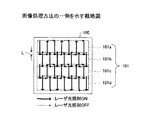
図1に、画像処理方法の一例を示す。図1は、画像記録領域101に画像が記録されている熱可逆記録媒体100にレーザ光を並列に走査して画像を消去し、隣接するレーザ光を走査する向きが反対である例である。
FIG. 1 shows an example of an image processing method. FIG. 1 shows an example in which the
このとき、レーザ光を並列に走査する画像記録領域101を、レーザ光を走査する方向に対して、4個の領域101a、101b、101c及び101dに分割し、隣接する領域101a及び101b、101b及び101c、101c及び101dは、重なり幅がLである重なりを有する。また、レーザ光を走査する方向は、画像記録領域101の短手方向である。
At this time, the
なお、図中、実線及び点線は、それぞれレーザ光が照射されている状態で走査されている動作(レーザ光描画線)及び隣接するレーザ光描画線間をレーザ光が照射されていない状態で走査されている動作である。 In the figure, the solid line and the dotted line are scanned in a state where the laser beam is irradiated (laser beam drawing line) and between adjacent laser beam drawing lines in a state where the laser beam is not irradiated. Is the behavior that has been done.
図2に、図1の画像処理方法において、画像記録領域101を分割しない方法を示す。
FIG. 2 shows a method in which the
この場合、レーザ光描画線の折り返し部以外におけるレーザ光の照射エネルギー密度を最適な条件に調整してレーザ光を走査すると、レーザ光描画線の折り返し部におけるレーザ光の照射エネルギー密度は、残存熱の影響を受けるため、過剰になる。 In this case, when the laser beam is scanned with the laser beam irradiation energy density adjusted to an optimum condition other than the laser beam drawing line folding part, the laser beam irradiation energy density at the laser beam drawing line folding part is determined by the residual heat. Because it is affected, it becomes excessive.
一方、レーザ光描画線の折り返し部におけるレーザ光の照射エネルギー密度を最適な条件に調整してレーザ光を走査すると、レーザ光描画線の折り返し部以外における照射エネルギー密度は、残存熱の影響を受けにくいため、不足する。 On the other hand, when the laser beam is scanned by adjusting the irradiation energy density of the laser beam at the folded portion of the laser beam drawing line to an optimum condition, the irradiation energy density at the portion other than the folded portion of the laser beam drawing line is affected by the residual heat. Because it is difficult, it is insufficient.
ここで、図1の画像処理方法のように、レーザ光を並列に走査する画像記録領域101を、レーザ光を走査する方向に対して、分割すると、レーザ光描画線の折り返し部以外における照射エネルギー密度も、残存熱の影響を受けるため、過剰になる。このため、レーザ光の走査速度を高くしたり、レーザ光の照射間隔を大きくしたりすることができ、その結果、画像を消去する時間を短縮することができる。
Here, as in the image processing method of FIG. 1, when the
図3に、画像処理方法の他の例を示す。図3は、画像記録領域101に画像が記録されている熱可逆記録媒体100にレーザ光を並列に走査して画像を消去し、隣接するレーザ光を走査する向きが同一である例である。
FIG. 3 shows another example of the image processing method. FIG. 3 shows an example in which the
このとき、レーザ光を並列に走査する画像記録領域101を、レーザ光を走査する方向に対して、4個の領域101a、101b、101c及び101dに分割し、隣接する領域101a及び101b、101b及び101c、101c及び101dは、重なり幅がLである重なりを有する。また、レーザ光を走査する方向は、画像記録領域101の短手方向である。
At this time, the
なお、図中、実線及び点線は、それぞれレーザ光が照射されている状態で走査されている動作(レーザ光描画線)及び隣接するレーザ光描画線間をレーザ光が照射されていない状態で走査されている動作である。 In the figure, the solid line and the dotted line are scanned in a state where the laser beam is irradiated (laser beam drawing line) and between adjacent laser beam drawing lines in a state where the laser beam is not irradiated. Is the behavior that has been done.
図4に、図3の画像処理方法において、画像記録領域101を分割しない方法を示す。
FIG. 4 shows a method in which the
この場合、レーザ光描画線の折り返し部以外におけるレーザ光の照射エネルギー密度を最適な条件に調整してレーザ光を走査すると、レーザ光描画線の折り返し部におけるレーザ光の照射エネルギー密度は、残存熱の影響を受けにくいため、過剰にならない。 In this case, when the laser beam is scanned with the laser beam irradiation energy density adjusted to an optimum condition other than the laser beam drawing line folding part, the laser beam irradiation energy density at the laser beam drawing line folding part is determined by the residual heat. Because it is difficult to be affected by, it does not become excessive.
ここで、図3の画像処理方法のように、画像記録領域101を、レーザ光を走査する方向に対して、分割すると、レーザ光描画線の照射エネルギー密度は、残存熱の影響を受けるため、過剰になる。このため、レーザ光の走査速度を高くしたり、レーザ光の照射間隔を大きくしたりすることができ、その結果、画像を消去する時間を短縮することができる。
Here, when the
図5に、画像処理方法の他の例を示す。図5は、画像記録領域101に画像が記録されている熱可逆記録媒体100にレーザ光を並列に走査して画像を消去し、隣接するレーザ光を走査する向きが同一である例である。
FIG. 5 shows another example of the image processing method. FIG. 5 is an example in which the
このとき、レーザ光を並列に走査する画像記録領域101を、レーザ光を走査する方向に対して、2個の領域101a及び101bに分割し、隣接する領域101a及び101bは、重なり幅がLである重なりを有する。また、レーザ光を走査する方向は、画像記録領域101の短手方向である。
At this time, the
なお、図中、実線及び点線は、それぞれレーザ光が照射されている状態で走査されている動作(レーザ光描画線)及び隣接するレーザ光描画線間をレーザ光が照射されていない状態で走査されている動作である。 In the figure, the solid line and the dotted line are scanned in a state where the laser beam is irradiated (laser beam drawing line) and between adjacent laser beam drawing lines in a state where the laser beam is not irradiated. Is the behavior that has been done.
図6に、画像処理方法の他の例を示す。図6は、画像記録領域101に画像が記録されている熱可逆記録媒体100にレーザ光を並列に走査して画像を消去し、隣接するレーザ光を走査する向きが同一である例である。
FIG. 6 shows another example of the image processing method. FIG. 6 shows an example in which the
このとき、レーザ光を並列に走査する画像記録領域101を、レーザ光を走査する方向に対して、6個の領域101a、101b、101c、101d、101e及び101fに分割し、隣接する領域101a及び101b、101b及び101c、101c及び101d、101d及び101e、101e及び101fは、重なり幅がLである重なりを有する。また、レーザ光を走査する方向は、画像記録領域101の短手方向である。
At this time, the
なお、図中、実線及び点線は、それぞれレーザ光が照射されている状態で走査されている動作(レーザ光描画線)及び隣接するレーザ光描画線間をレーザ光が照射されていない状態で走査されている動作である。 In the figure, the solid line and the dotted line are scanned in a state where the laser beam is irradiated (laser beam drawing line) and between adjacent laser beam drawing lines in a state where the laser beam is not irradiated. Is the behavior that has been done.
レーザ光を並列に走査する画像記録領域101を、レーザ光を走査する方向に対して、分割する個数は、通常、2〜100であり、2〜80であることが好ましい。レーザ光を並列に走査する画像記録領域101を、レーザ光を走査する方向に対して、分割する個数が100を超えると、熱可逆記録媒体100に記録されている画像を消去する時間が長くなることがある。
The number of divisions of the
レーザ光のスポット径に対するレーザ光描画線の長さの比は、通常、1.5以上である。レーザ光のスポット径に対するレーザ光描画線の長さの比が1.5未満であると、熱可逆記録媒体100に記録されている画像を消去する時間が長くなることがある。
The ratio of the length of the laser beam drawing line to the laser beam spot diameter is usually 1.5 or more. When the ratio of the length of the laser beam drawing line to the laser beam spot diameter is less than 1.5, the time for erasing the image recorded on the
レーザ光を走査する方向は、画像記録領域101の短手方向であることが好ましい。これにより、熱可逆記録媒体100に記録されている画像を短時間で消去することができる。
The scanning direction of the laser beam is preferably the short direction of the
なお、レーザ光を並列に走査する画像記録領域101を均等に分割してもよいし、不均等に分割してもよい。
Note that the
また、レーザ光を並列に走査する画像記録領域101を、レーザ光の走査方向に対して垂直な方向に対して、さらに分割してもよい。
Further, the
画像を消去する際に照射されるレーザ光の出力は、通常、5W以上であり、7W以上であることが好ましく、10W以上であることがさらに好ましい。画像を消去する際に照射されるレーザ光の出力が5W未満であると、画像の消去に時間がかかることがある。また、画像を消去する際に照射されるレーザ光の出力は、通常、200W以下であり、190W以下であることが好ましく、180W以下であることがさらに好ましい。画像を消去する際に照射されるレーザ光の出力が200Wを超えると、レーザ装置の大型化を招くことがある。 The output of the laser beam irradiated when erasing the image is usually 5 W or more, preferably 7 W or more, and more preferably 10 W or more. If the output of the laser beam irradiated when erasing the image is less than 5 W, it may take time to erase the image. Further, the output of the laser beam irradiated when erasing the image is usually 200 W or less, preferably 190 W or less, and more preferably 180 W or less. If the output of the laser beam irradiated when erasing the image exceeds 200 W, the laser device may be increased in size.
画像を消去する際に照射されるレーザ光の走査速度は、通常、100mm/s以上であり、200mm/s以上であることが好ましく、300mm/s以上であることがさらに好ましい。画像を消去する際に照射されるレーザ光の走査速度が100mm/s未満であると、画像の消去に時間がかかることがある。また、画像を消去する際に照射されるレーザ光の走査速度は、通常、15000mm/s以下であり、10000mm/s以下であることが好ましく、8000mm/s以下であることがさらに好ましい。画像を消去する際に照射されるレーザ光の走査速度が15000mm/sを超えると、均一に画像を消去しにくくなることがある。 The scanning speed of the laser beam irradiated when erasing the image is usually 100 mm / s or more, preferably 200 mm / s or more, and more preferably 300 mm / s or more. If the scanning speed of the laser beam irradiated when erasing the image is less than 100 mm / s, it may take time to erase the image. Moreover, the scanning speed of the laser beam irradiated when erasing an image is usually 15000 mm / s or less, preferably 10,000 mm / s or less, and more preferably 8000 mm / s or less. If the scanning speed of the laser beam irradiated when erasing the image exceeds 15000 mm / s, it may be difficult to erase the image uniformly.
画像を消去する際に照射されるレーザ光のスポット径は、通常、0.5mm以上であり、1.0mm以上であることが好ましく、2.0mm以上であることがさらに好ましい。画像を消去する際に照射されるレーザ光のスポット径が0.5mm未満であると、画像の消去に時間がかかることがある。また、画像を消去する際に照射されるレーザ光のスポット径は、通常、14.0mm以下であり、12.0mm以下であることが好ましく、10.0mm以下であることがさらに好ましい。画像を消去する際に照射されるレーザ光のスポット径が14.0mmを超えると、出力が不足して画像の消去不良が発生することがある。 The spot diameter of the laser beam irradiated when erasing the image is usually 0.5 mm or more, preferably 1.0 mm or more, and more preferably 2.0 mm or more. If the spot diameter of the laser beam irradiated when erasing the image is less than 0.5 mm, it may take time to erase the image. Further, the spot diameter of the laser beam irradiated when erasing the image is usually 14.0 mm or less, preferably 12.0 mm or less, and more preferably 10.0 mm or less. If the spot diameter of the laser beam irradiated when erasing an image exceeds 14.0 mm, the output may be insufficient and an image erasing failure may occur.
なお、画像が記録されていない熱可逆記録媒体に対して画像消去工程を行ってもよい。 Note that the image erasing step may be performed on a thermoreversible recording medium on which no image is recorded.
画像記録工程は、画像が消去された後、画像が消去される前又は画像が記録されていない熱可逆記録媒体を加熱することにより画像を記録する工程である。 The image recording step is a step of recording an image after the image is erased, before the image is erased or by heating a thermoreversible recording medium on which no image is recorded.
熱可逆記録媒体を加熱する方法としては、特に限定されないが、レーザ光等を用いる非接触加熱方法、サーマルヘッド等を用いる接触加熱方法等が挙げられる。中でも、物流ラインを想定した場合、熱可逆記録媒体の表面に凹凸が生じていても影響が少なく、離れた位置から記録することが可能であることから、レーザ光を照射する方法が好ましい。 A method for heating the thermoreversible recording medium is not particularly limited, and examples thereof include a non-contact heating method using a laser beam and the like, a contact heating method using a thermal head and the like. In particular, when a distribution line is assumed, a method of irradiating with laser light is preferable because even if irregularities are generated on the surface of the thermoreversible recording medium, there is little influence and recording can be performed from a remote position.
このとき、熱可逆記録媒体の全面に画像を記録してもよいし、熱可逆記録媒体の上下左右に余白部を設けて画像を記録してもよい。 At this time, an image may be recorded on the entire surface of the thermoreversible recording medium, or an image may be recorded by providing blank portions on the top, bottom, left and right of the thermoreversible recording medium.
画像を記録する際に照射されるレーザ光の出力は、通常、1W以上であり、3W以上であることが好ましく、5W以上であることがさらに好ましい。画像を記録する際に照射されるレーザ光の出力が1W未満であると、画像の記録に時間がかかることがある。また、画像を記録する際に照射されるレーザ光の出力は、通常、200W以下であり、150W以下であることが好ましく、100W以下であることがさらに好ましい。画像を記録する際に照射されるレーザ光の出力が200Wを超えると、レーザ装置の大型化を招くことがある。 The output of the laser beam irradiated when recording an image is usually 1 W or more, preferably 3 W or more, and more preferably 5 W or more. If the output of the laser beam irradiated when recording an image is less than 1 W, it may take time to record the image. Further, the output of the laser beam irradiated when recording an image is usually 200 W or less, preferably 150 W or less, and more preferably 100 W or less. If the output of the laser beam irradiated when recording an image exceeds 200 W, the laser device may be increased in size.
画像を記録する際に照射されるレーザ光の走査速度は、通常、300mm/s以上であり、500mm/s以上であることが好ましく、700mm/s以上であることがさらに好ましい。画像を記録する際に照射されるレーザ光の走査速度が300mm/s未満であると、画像の記録に時間がかかることがある。また、画像を記録する際に照射されるレーザ光の走査速度は、通常、15000mm/s以下であり、10000mm/s以下であることが好ましく、8000mm/s以下であることがさらに好ましい。画像を記録する際に照射されるレーザ光の走査速度が15000mm/sを超えると、均一に画像を形成しにくくなることがある。 The scanning speed of the laser beam irradiated when recording an image is usually 300 mm / s or more, preferably 500 mm / s or more, and more preferably 700 mm / s or more. If the scanning speed of the laser beam irradiated when recording an image is less than 300 mm / s, it may take time to record the image. In addition, the scanning speed of the laser light irradiated when recording an image is usually 15000 mm / s or less, preferably 10,000 mm / s or less, and more preferably 8000 mm / s or less. If the scanning speed of the laser beam irradiated when recording an image exceeds 15000 mm / s, it may be difficult to form an image uniformly.
画像を記録する際に照射されるレーザ光のスポット径は、通常、0.02mm以上であり、0.1mm以上であることが好ましく、0.15mm以上であることがさらに好ましい。画像を記録する際に照射されるレーザ光のスポット径が0.02mm未満であると、画像の線幅が細くなり、視認性が低下することがある。また、画像を記録する際に照射されるレーザ光のスポット径は、通常、3.0mm以下であり、2.5mm以下であることが好ましく、2.0mm以下であることがさらに好ましい。画像を記録する際に照射されるレーザ光のスポット径が3.0mmを超えると、画像の線幅が太くなり、隣接する線が重なり、小さい画像を記録しにくくなることがある。 The spot diameter of the laser beam irradiated when recording an image is usually 0.02 mm or more, preferably 0.1 mm or more, and more preferably 0.15 mm or more. When the spot diameter of the laser beam irradiated when recording an image is less than 0.02 mm, the line width of the image becomes narrow and visibility may be lowered. Further, the spot diameter of the laser beam irradiated when recording an image is usually 3.0 mm or less, preferably 2.5 mm or less, and more preferably 2.0 mm or less. If the spot diameter of the laser beam irradiated when recording an image exceeds 3.0 mm, the line width of the image becomes thick, and adjacent lines may overlap, making it difficult to record a small image.
レーザ光の光源としては、特に限定されないが、半導体レーザ、YAGレーザ、ファイバレーザ、CO2レーザ等が挙げられる。中でも、波長選択性が広く、光源自体が小さく、装置の小型化、低価格化が可能である点から、半導体レーザが好ましい。 The light source of the laser light is not particularly limited, and examples thereof include a semiconductor laser, a YAG laser, a fiber laser, and a CO 2 laser. Among these, a semiconductor laser is preferable because it has a wide wavelength selectivity, a small light source, and a reduction in size and cost of the apparatus.
半導体レーザ、YAGレーザ、ファイバレーザから照射されるレーザ光の波長は、通常、700nm以上であり、720nm以上であることが好ましく、750nm以上であることがさらに好ましい。画像を記録する際に、半導体レーザ、YAGレーザ、ファイバレーザから照射されるレーザ光の波長が700nm未満の可視光領域であると、熱可逆記録媒体に記録された画像のコントラストが低下したり、熱可逆記録媒体が着色したりすることがある。半導体レーザ、YAGレーザ、ファイバレーザから照射されるレーザ光の波長が紫外光領域であると、熱可逆記録媒体が劣化しやすくなることがある。また、熱可逆記録媒体に添加する光熱変換材料は、耐久性を確保するために高い分解温度を必要とし、光熱変換材料として、有機色素を用いる場合、分解温度が高く吸収波長が長い光熱変換材料を得るのは難しい。このため、半導体レーザ、YAGレーザ、ファイバレーザから照射されるレーザ光の波長は、通常、2000nm以下であり、1500mm以下であることが好ましく、1200nm以下であることがさらに好ましい。 The wavelength of laser light emitted from a semiconductor laser, YAG laser, or fiber laser is usually 700 nm or more, preferably 720 nm or more, and more preferably 750 nm or more. When recording an image, if the wavelength of laser light emitted from a semiconductor laser, YAG laser, or fiber laser is in the visible light region of less than 700 nm, the contrast of the image recorded on the thermoreversible recording medium is reduced, The thermoreversible recording medium may be colored. When the wavelength of laser light emitted from a semiconductor laser, YAG laser, or fiber laser is in the ultraviolet region, the thermoreversible recording medium may be easily deteriorated. In addition, the photothermal conversion material added to the thermoreversible recording medium requires a high decomposition temperature in order to ensure durability. When an organic dye is used as the photothermal conversion material, the photothermal conversion material has a high decomposition temperature and a long absorption wavelength. Hard to get. For this reason, the wavelength of the laser light emitted from the semiconductor laser, YAG laser, or fiber laser is usually 2000 nm or less, preferably 1500 mm or less, and more preferably 1200 nm or less.
CO2レーザから照射されるレーザ光の波長は、遠赤外領域の10.6μmであり、レーザ光を吸収して発熱させるための添加物を添加しなくても、熱可逆記録媒体の表面でレーザ光を吸収する。また、添加物は、近赤外領域の波長を有するレーザ光を用いても、若干ではあるが、可視光も吸収することがあるため、添加物が不要となるCO2レーザは、熱可逆記録媒体に記録された画像のコントラストの低下を抑制することができる。 The wavelength of the laser light emitted from the CO 2 laser is 10.6 μm in the far infrared region, and even on the surface of the thermoreversible recording medium without adding an additive for absorbing the laser light and generating heat. Absorbs laser light. In addition, even if a laser beam having a wavelength in the near-infrared region is used as an additive, visible light may also be absorbed, but a CO 2 laser that does not require an additive is used for thermoreversible recording. A decrease in contrast of an image recorded on a medium can be suppressed.
図4に、画像処理装置の一例を示す。 FIG. 4 shows an example of the image processing apparatus.
画像処理装置は、レーザ発振器1、ビームエキスパンダ2、スキャンニングユニット5から構成されている発振器ユニットを有する。 The image processing apparatus has an oscillator unit including a laser oscillator 1, a beam expander 2, and a scanning unit 5.
レーザ発振器1は、レーザ媒質の両側にミラーを配置し、レーザ媒質をポンピングし、励起状態の原子数を増やし反転分布を形成して誘導放出させる。その結果、光軸方向の光のみが選択的に増幅されることにより、光の指向性が高まり、出力ミラーからレーザ光が放出される。 The laser oscillator 1 arranges mirrors on both sides of the laser medium, pumps the laser medium, increases the number of excited atoms, forms an inversion distribution, and stimulates emission. As a result, only the light in the optical axis direction is selectively amplified, so that the directivity of the light is increased and the laser light is emitted from the output mirror.
スキャンニングユニット5は、ガルバノメータ4と、ガルバノメータ4に取り付けられたミラー4Aから構成されている。そして、レーザ発振器1から出力されたレーザ光を、ガルバノメータ4に取り付けられたX軸方向とY軸方向との2枚のミラー4Aで回転走査することにより、熱可逆記録媒体100に、画像を記録又は消去する。
The scanning unit 5 includes a galvanometer 4 and a
画像処理装置は、レーザ媒質を励起する光源の駆動電源、ガルバノメータの駆動電源、ペルチェ素子等の冷却用電源、各ユニットを制御する制御部から構成されている電源制御ユニットを有する。 The image processing apparatus includes a power source control unit that includes a drive power source for a light source that excites a laser medium, a drive power source for a galvanometer, a cooling power source for a Peltier element, and a control unit that controls each unit.
画像処理装置は、タッチパネル入力、キーボード入力により、画像を記録又は消去するために、レーザ光の強さ、レーザ走査の速度等の条件を入力し、画像を作成及び編集するプログラムユニットを有する。 The image processing apparatus has a program unit for inputting and creating an image by inputting conditions such as laser light intensity and laser scanning speed in order to record or erase an image by touch panel input or keyboard input.
なお、画像処理装置は、熱可逆記録媒体100を搬送する搬送ユニット、タッチパネル等をさらに有する。
The image processing apparatus further includes a transport unit that transports the
熱可逆記録媒体100は、支持体上に、熱可逆記録層が形成されており、必要に応じて、光熱変換層、酸素遮断層、紫外線吸収層、中間層、保護層、アンダー層、バック層、接着層、粘着層、着色層、空気層、光反射層等がさらに形成されている。
The
なお、これらの各層は、単層構造であってもよいし、積層構造であってもよい。 Each of these layers may have a single layer structure or a laminated structure.
また、光熱変換材料を添加する場合は、熱可逆記録層又は光熱変換層に添加されるが、記録感度の点から、熱可逆記録層に添加されることが好ましい。 In addition, when a photothermal conversion material is added, it is added to the thermoreversible recording layer or the photothermal conversion layer, but it is preferably added to the thermoreversible recording layer from the viewpoint of recording sensitivity.
光熱変換材料は、無機系材料と有機系材料に大別できる。 Photothermal conversion materials can be broadly classified into inorganic materials and organic materials.
無機系材料としては、特に限定されないが、カーボンブラック、Ge、Bi、In、Te、Se、Cr等の金属又は半金属、金属又は半金属を含む合金、金属ホウ化物、金属酸化物が挙げられる。 The inorganic material is not particularly limited, and examples thereof include metals or metalloids such as carbon black, Ge, Bi, In, Te, Se, and Cr, alloys containing metal or metalloid, metal borides, and metal oxides. .
金属ホウ化物及び金属酸化物としては、六ホウ化物、酸化タングステン、アンチモンドープ酸化スズ(ATO)、スズドープ酸化インジウム(ITO)、アンチモン酸亜鉛等が挙げられる。中でも、可視領域に吸収が少ないことから、六ホウ化物、酸化タングステンが好ましい。 Examples of the metal boride and metal oxide include hexaboride, tungsten oxide, antimony-doped tin oxide (ATO), tin-doped indium oxide (ITO), and zinc antimonate. Among these, hexaboride and tungsten oxide are preferable because of less absorption in the visible region.
有機系材料としては、特に限定されないが、光源として半導体レーザを用いる場合には、700〜1500nmの波長領域に吸収ピークを有する近赤外吸収色素が用いられる。 Although it does not specifically limit as an organic material, When using a semiconductor laser as a light source, the near-infrared absorption pigment | dye which has an absorption peak in a 700-1500 nm wavelength range is used.
近赤外吸収色素としては、シアニン色素、キノン系色素、インドナフトールのキノリン誘導体、フェニレンジアミン系ニッケル錯体、フタロシアニン系化合物等が挙げられ、二種以上併用してもよい。中でも、耐熱性に優れる点から、フタロシアニン系化合物が好ましい。 Examples of near infrared absorbing dyes include cyanine dyes, quinone dyes, quinoline derivatives of indonaphthol, phenylenediamine nickel complexes, phthalocyanine compounds, and the like, and two or more of them may be used in combination. Of these, phthalocyanine compounds are preferred because of their excellent heat resistance.
図8に、熱可逆記録媒体の層構成の第一の例を示す。 FIG. 8 shows a first example of the layer structure of the thermoreversible recording medium.
熱可逆記録媒体100Aは、支持体110上に、熱可逆記録層120が形成されている。
In the
図9に、熱可逆記録媒体の層構成の第二の例を示す。 FIG. 9 shows a second example of the layer structure of the thermoreversible recording medium.
熱可逆記録媒体100Bは、支持体110上に、熱可逆記録層120及び光熱変換層130が順次積層されている。
In the
なお、熱可逆記録層120及び光熱変換層130を積層する順序は逆であってもよい。
The order in which the
図10に、熱可逆記録媒体の層構成の第三の例を示す。 FIG. 10 shows a third example of the layer structure of the thermoreversible recording medium.
熱可逆記録媒体100Cは、支持体110上に、熱可逆記録層120A、光熱変換層130及び熱可逆記録層120Bが順次積層されている。
In the thermoreversible recording medium 100C, a
支持体110の形状としては、特に限定されないが、平板状等が挙げられる。
Although it does not specifically limit as a shape of the
支持体110の構造は、単層構造であってもよいし、積層構造であってもよい。
The structure of the
支持体110を構成する材料としては、特に限定されないが、ガラス、石英、シリコン、酸化ケイ素、酸化アルミニウム、金属等の無機材料、紙、三酢酸セルロース等のセルロース誘導体、合成紙、ポリエチレンテレフタレート、ポリカーボネート、ポリスチレン、ポリメタクリル酸メチル等の有機材料が挙げられ、二種以上を併用してもよい。中でも、有機材料が好ましく、ポリエチレンテレフタレート、ポリカーボネート、ポリメタクリル酸メチルがさらに好ましく、ポリエチレンテレフタレートが特に好ましい。
The material constituting the
支持体110は、表面改質されていることが好ましい。これにより、塗布層の接着性を向上させることができる。
The
表面改質処理としては、特に限定されないが、コロナ放電処理、酸化反応処理(例えば、クロム酸処理)、エッチング処理、易接着処理、帯電防止処理等が挙げられる。 The surface modification treatment is not particularly limited, and examples thereof include corona discharge treatment, oxidation reaction treatment (for example, chromic acid treatment), etching treatment, easy adhesion treatment, and antistatic treatment.
支持体110は、酸化チタン等の白色顔料を含むことが好ましい。
The
支持体110の平均厚さは、通常、10μm〜2mmであり、20μm〜1mmであることが好ましい。
The average thickness of the
なお、支持体110を省略することもできる。
Note that the
熱可逆記録層120は、温度に依存して透明度及び色調のいずれかが可逆的に変化する材料を含む。
The
温度に依存して透明度及び色調のいずれかが可逆的に変化する材料は、温度変化により、目に見える変化を可逆的に生じる現象を発現することが可能な材料であり、加熱温度及び加熱後の冷却速度の違いにより、相対的に発色した状態と消色した状態に変化することが可能である。この場合、目に見える変化は、色の状態の変化と形状の変化に分けられる。色の状態の変化は、例えば、透過率、反射率、吸収波長、散乱度等の変化に起因し、熱可逆記録媒体は、実際には、これらの変化の組み合わせにより色の状態が変化する。 A material whose transparency and color tone reversibly change depending on the temperature is a material that can exhibit a phenomenon that causes a visible change reversibly due to temperature change. Depending on the difference in cooling rate, it is possible to change between a relatively colored state and a decolored state. In this case, the visible change is divided into a color state change and a shape change. The change in the color state is caused by, for example, changes in transmittance, reflectance, absorption wavelength, scattering degree, etc., and the color state of the thermoreversible recording medium actually changes depending on a combination of these changes.
温度に依存して透明度及び色調のいずれかが可逆的に変化する材料としては、特に限定されないが、第一の特定温度で透明状態となり、第二の特定温度で白濁状態となる材料(特開昭55−154198号公報参照)、第二の特定温度で発色し、第一の特定温度で消色する材料(特開平4−224996号公報、特開平4−247985号公報、特開平4−267190号公報等参照)、第一の特定温度で白濁状態となり、第二の特定温度で透明状態となる材料(特開平3−169590号公報参照)、第一の特定温度で黒、赤、青等に発色し、第二の特定温度で消色する材料(特開平2−188293号、特開平2−188294号公報等参照)等が挙げられる。中でも、透明状態と発色状態とを可逆的に示し、コントラストが高い画像を記録できる点で、ロイコ染料と顕色剤を用いることが好ましい。 The material in which either the transparency or the color tone reversibly changes depending on the temperature is not particularly limited. However, the material becomes transparent at the first specific temperature and becomes cloudy at the second specific temperature (Japanese Patent Application Laid-Open Sho 55-154198), materials that develop color at the second specific temperature and erase at the first specific temperature (Japanese Patent Laid-Open Nos. 4-224996, 4-247985, and 4-267190) No., etc.), a material that becomes cloudy at the first specific temperature and becomes transparent at the second specific temperature (see JP-A-3-169590), black, red, blue, etc. at the first specific temperature And a material that can be erased at a second specific temperature (see JP-A-2-188293, JP-A-2-188294, etc.). Among them, it is preferable to use a leuco dye and a developer from the viewpoint of reversibly showing a transparent state and a colored state and recording an image having a high contrast.
ロイコ染料は、無色又は淡色の染料前駆体である。 A leuco dye is a colorless or light-colored dye precursor.
ロイコ染料としては、特に限定されないが、トリフェニルメタンフタリド系、トリアリルメタン系、フルオラン系、フェノチアジン系、チオフェルオラン系、キサンテン系、インドフタリル系、スピロピラン系、アザフタリド系、クロメノピラゾール系、メチン系、ローダミンアニリノラクタム系、ローダミンラクタム系、キナゾリン系、ジアザキサンテン系、ビスラクトン系等が挙げられ、二種以上併用してもよい。中でも、発消色特性、色彩、保存性に優れる点で、フルオラン系又はフタリド系のロイコ染料が好ましい。 The leuco dye is not particularly limited, but is triphenylmethanephthalide, triallylmethane, fluoran, phenothiazine, thioferolane, xanthene, indophthalyl, spiropyran, azaphthalide, chromenopyrazole, Examples thereof include methine series, rhodamine anilinolactam series, rhodamine lactam series, quinazoline series, diazaxanthene series, and bislactone series, and two or more kinds may be used in combination. Among these, fluoran-based or phthalide-based leuco dyes are preferable in terms of excellent color development / decoloring properties, color, and storage stability.
顕色剤としては、熱を因子として可逆的に発消色させることが可能であれば、特に限定されないが、ロイコ染料を発色させる顕色能を有する構造(例えば、フェノール性水酸基、カルボキシル基、リン酸基)及び分子間の凝集力を制御する構造(例えば、長鎖炭化水素基)を1個以上有する化合物が挙げられる。 The developer is not particularly limited as long as it can reversibly develop and decolorize by using heat as a factor. And a compound having at least one structure (for example, a long-chain hydrocarbon group) that controls the cohesive force between phosphoric acid groups and molecules.
ロイコ染料を発色させる顕色能を有する構造は、フェノール性水酸基であることが好ましい。 The structure having a color developing ability to develop a leuco dye is preferably a phenolic hydroxyl group.
長鎖炭化水素基の炭素数は、通常、8以上であり、11以上であることが好ましい。また、長鎖炭化水素基の炭素数は、通常、40以下であり、30以下であることが好ましい。 The carbon number of the long chain hydrocarbon group is usually 8 or more and preferably 11 or more. Moreover, carbon number of a long chain hydrocarbon group is 40 or less normally, and it is preferable that it is 30 or less.
なお、ロイコ染料を発色させる顕色能を有する構造及び分子間の凝集力を制御する構造は、ヘテロ原子を含む2価以上の連結基を介して、連結されていてもよい。また、長鎖炭化水素基中に、同様の連結基及び/又は芳香族基により置換されていてもよい。 In addition, the structure having a color developing ability for causing the leuco dye to develop and the structure for controlling the cohesive force between molecules may be linked via a divalent or higher valent linking group containing a hetero atom. Further, the long chain hydrocarbon group may be substituted with the same linking group and / or aromatic group.
顕色剤は、一般式 Developer is a general formula

で表される化合物であることが好ましく、一般式
Is preferably a compound represented by the general formula
R2の炭素数は、5以上であることが好ましく、10以上であることがさらに好ましい。 R 2 preferably has 5 or more carbon atoms, more preferably 10 or more.
R3の炭素数は、6以上であることが好ましく、8以上であることがさらに好ましい。 R 3 preferably has 6 or more carbon atoms, more preferably 8 or more.
R1、R2及びR3の炭素数の和は、通常、8以上であり、11以上であることが好ましい。また、R1、R2及びR3の炭素数の和は、通常、40以下であり、35以下であることが好ましい。R1、R2及びR3の炭素数の和が8未満であると、発色の安定性及び消色性が低下することがある。 The sum of the carbon number of R 1 , R 2 and R 3 is usually 8 or more and preferably 11 or more. Moreover, the sum of the carbon numbers of R 1 , R 2 and R 3 is usually 40 or less, and preferably 35 or less. When the sum of the carbon numbers of R 1 , R 2 and R 3 is less than 8, the color development stability and decoloring property may be lowered.
脂肪族炭化水素基は、直鎖であってもよいし、分枝鎖であってもよく、不飽和結合を有していてもよいが、直鎖であることが好ましい。 The aliphatic hydrocarbon group may be linear or branched, and may have an unsaturated bond, but is preferably linear.
置換基としては、特に限定されないが、水酸基、ハロゲン原子、アルコキシ基等が挙げられる。 Although it does not specifically limit as a substituent, A hydroxyl group, a halogen atom, an alkoxy group, etc. are mentioned.
N原子又はO原子を含む2価の基としては、特に限定されないが、酸素原子、アミド結合(−NHCO−)、尿素結合(−HNCONH−)、化学式
−COHN−NHCO−
で表される基、化学式
−HNCO−CONH−
で表される基、化学式
−HNCONHCO−
で表される基等が挙げられる。中でも、アミド結合、尿素結合が好ましい。
Although it does not specifically limit as bivalent group containing N atom or O atom, An oxygen atom, an amide bond (-NHCO-), a urea bond (-HNCONH-), Chemical formula -COHN-NHCO-
A group represented by the formula: -HNCO-CONH-
A group represented by the formula: -HNCONHCO-
The group etc. which are represented by these are mentioned. Of these, an amide bond and a urea bond are preferable.
なお、顕色剤は、熱可逆記録層120中に、粒子状に分散して存在している。
The developer is dispersed in the form of particles in the
熱可逆記録層120は、消色促進剤をさらに含むことが好ましい。
The
消色促進剤としては、アミド結合(−NHCO−)及び/又は化学式
−OCONH−
で表される基を1個以上有していれば、特に限定されない。
As the decoloring accelerator, amide bond (—NHCO—) and / or chemical formula —OCONH—
If it has one or more groups represented by, it will not specifically limit.
消色促進剤は、消色状態を形成する過程において、顕色剤との間に、分子間相互作用が誘起され、発消色特性を向上させることができる。 In the process of forming a decolored state, the decoloring accelerator induces an intermolecular interaction with the developer, and can improve the color development / decoloring characteristics.
熱可逆記録層120は、塗布特性及び発消色特性を向上させるために、添加剤をさらに含んでいてもよい。
The
添加剤としては、特に限定されないが、界面活性剤、導電剤、充填剤、酸化防止剤、光安定化剤、発色安定化剤等が挙げられる。 Although it does not specifically limit as an additive, Surfactant, a electrically conductive agent, a filler, antioxidant, a light stabilizer, a coloring stabilizer, etc. are mentioned.
熱可逆記録層120は、バインダー樹脂をさらに含んでいてもよい。
The
バインダー樹脂としては、特に限定されないが、繰り返し時の耐久性を向上させるため、架橋剤により硬化することが可能な熱可塑性樹脂、熱硬化性樹脂、紫外線硬化性樹脂、電子線硬化性樹脂が好ましく、架橋剤により硬化することが可能な熱可塑性樹脂が特に好ましい。 The binder resin is not particularly limited, but is preferably a thermoplastic resin, a thermosetting resin, an ultraviolet curable resin, or an electron beam curable resin that can be cured by a crosslinking agent in order to improve durability during repetition. A thermoplastic resin that can be cured by a crosslinking agent is particularly preferred.
架橋剤により硬化することが可能な熱可塑性樹脂としては、特に限定されないが、架橋剤と反応することが可能な基を有していれば、特に限定されないが、フェノキシ樹脂、ポリビニルブチラール、セルロースアセテートプロピオネート、セルロースアセテートブチレート、アクリルポリオール、ポリエステルポリオール、ポリウレタンポリオール等が挙げられる。中でも、アクリルポリオール、ポリエステルポリオール、ポリウレタンポリオールが好ましい。 The thermoplastic resin that can be cured by the crosslinking agent is not particularly limited, but is not particularly limited as long as it has a group capable of reacting with the crosslinking agent, but is not limited thereto. Examples include propionate, cellulose acetate butyrate, acrylic polyol, polyester polyol, and polyurethane polyol. Among these, acrylic polyol, polyester polyol, and polyurethane polyol are preferable.
ロイコ染料に対するバインダー樹脂の質量比は、通常、0.1〜10である。ロイコ染料に対するバインダー樹脂の質量比が0.1未満であると、熱可逆記録層120の熱強度が低下することがあり、10を超えると、発色濃度が低下することがある。
The mass ratio of the binder resin to the leuco dye is usually 0.1 to 10. When the mass ratio of the binder resin to the leuco dye is less than 0.1, the thermal strength of the
架橋剤としては、特に限定されないが、イソシアネート類、アミノ樹脂、フェノール樹脂、アミン類、エポキシ化合物等が挙げられる。でも、イソシアネート類が好ましく、イソシアネート基を複数有するポリイソシアネートが特に好ましい。 Although it does not specifically limit as a crosslinking agent, Isocyanates, amino resin, a phenol resin, amines, an epoxy compound, etc. are mentioned. However, isocyanates are preferred, and polyisocyanates having a plurality of isocyanate groups are particularly preferred.
熱可塑性樹脂が有する架橋剤と反応することが可能な基に対する架橋剤が有する活性基のモル比は、通常、0.01〜2である。熱可塑性樹脂が有する架橋剤と反応することが可能な基に対する架橋剤が有する活性基のモル比が0.01未満であると、熱可逆記録層120の熱強度が低下することがあり、2を超えると、発消色特性が低下することがある。
The molar ratio of the active group of the crosslinking agent to the group capable of reacting with the crosslinking agent of the thermoplastic resin is usually 0.01-2. When the molar ratio of the active group possessed by the crosslinking agent to the group capable of reacting with the crosslinking agent possessed by the thermoplastic resin is less than 0.01, the thermal strength of the
架橋剤は、架橋反応の触媒と併用してもよい。 The crosslinking agent may be used in combination with a catalyst for the crosslinking reaction.
熱可逆記録層120のゲル分率は、通常、30%以上であり、50%以上であることが好ましく、70%以上であることがさらに好ましい。熱可逆記録層120のゲル分率が30%未満であると、熱可逆記録媒体100の耐久性が低下することがある。
The gel fraction of the
熱可逆記録層120を形成する方法としては、特に限定されないが、バインダー樹脂、ロイコ染料及び顕色剤を含む組成物が溶媒中に溶解又は分散している塗布液を支持体上に塗布した後、乾燥させる方法等が挙げられる。
A method for forming the
溶媒としては、特に限定されないが、テトラヒドロフラン、メチルエチルケトン、メチルイソブチルケトン、クロロホルム、四塩化炭素、エタノール、トルエン、ベンゼン等が挙げられる。 Although it does not specifically limit as a solvent, Tetrahydrofuran, methyl ethyl ketone, methyl isobutyl ketone, chloroform, carbon tetrachloride, ethanol, toluene, benzene etc. are mentioned.
塗布液の調製方法としては、特に限定されないが、組成物を溶媒中に溶解又は分散させる方法、バインダー樹脂を溶媒中に溶解させた後、バインダー樹脂以外の材料を溶解又は分散させる方法等が挙げられる。 The method for preparing the coating solution is not particularly limited, and examples thereof include a method for dissolving or dispersing the composition in a solvent, a method for dissolving or dispersing a material other than the binder resin after dissolving the binder resin in the solvent, and the like. It is done.
塗布液は、消泡剤、スリップ剤、防腐剤、架橋剤、可塑剤等をさらに含んでいてもよい。 The coating solution may further contain an antifoaming agent, slip agent, preservative, crosslinking agent, plasticizer and the like.
塗布液の塗布方法としては、特に限定されないが、ブレード塗布法、ワイヤーバー塗布法、スプレー塗布法、エアナイフ塗布法、ビード塗布法、カーテン塗布法、グラビア塗布法、キス塗布法、リバースロール塗布法、ディップ塗布法、ダイ塗布法等が挙げられる。 The application method of the coating liquid is not particularly limited, but blade coating method, wire bar coating method, spray coating method, air knife coating method, bead coating method, curtain coating method, gravure coating method, kiss coating method, reverse roll coating method , Dip coating method, die coating method and the like.
熱可逆記録層120の平均厚さは、通常、1〜20μmであり、3〜18μmであることが好ましい。熱可逆記録層の平均厚さが1μm未満であると、発色濃度が低下することがあり、20μmを超えると、発色温度に達せず、発色しない部分が発生することがある。
The average thickness of the
光熱変換層130は、光熱変換材料を含み、熱可逆記録層120の片面又は両面に形成される。
The
光熱変換層130中の光熱変換材料の含有量は、通常、0.005〜20g/m2であり、0.01〜10g/m2であることが好ましい。
The content of the photothermal conversion material in the light-to-
光熱変換層130は、バインダー樹脂をさらに含んでいてもよい。
The
バインダー樹脂としては、熱可塑性樹脂及び熱硬化性樹脂のいずれを用いてもよく、熱可逆記録層120のバインダー樹脂と同様の樹脂を用いることができる。中でも、耐久性を向上させるため、熱硬化性樹脂、紫外線硬化性樹脂、電子線硬化性樹脂が好ましく、架橋剤により硬化することが可能な熱硬化性樹脂が好ましい。
As the binder resin, either a thermoplastic resin or a thermosetting resin may be used, and the same resin as the binder resin of the
光熱変換層130の平均厚さは、通常、0.1〜20μmである。
The average thickness of the
熱可逆記録層120と光熱変換層130の間に、バリア層を形成してもよい。
A barrier layer may be formed between the
バリア層は、バインダー樹脂を含む。 The barrier layer includes a binder resin.
バインダー樹脂としては、特に限定されないが、熱硬化性樹脂、紫外線硬化性樹脂、電子線硬化性樹脂等が挙げられる。 The binder resin is not particularly limited, and examples thereof include a thermosetting resin, an ultraviolet curable resin, and an electron beam curable resin.
熱可逆記録層120又は光熱変換層130上に、酸素遮断層をさらに形成してもよい。これにより、熱可逆記録層120や光熱変換層130に酸素が進入することを防ぐことにより、熱可逆記録層120中のロイコ染料の光劣化を防止することができると共に、繰り返し高温に加熱されることによる光熱変換材料の酸化を防止することができる。
An oxygen blocking layer may be further formed on the
酸素遮断層の25℃、80%RHにおける酸素透過度は、通常、0.5mL/(m2・24hr・atm)以下であり、0.1mL/(m2・24hr・atm)以下であることが好ましく、0.05mL/(m2・24hr・atm)以下であることがさらに好ましい。酸素遮断層の25℃、80%RHにおける酸素透過度が0.5mL/(m2・24hr・atm)を超えると、十分に酸素を遮断することができなくなることがある。 The oxygen permeability of the oxygen barrier layer at 25 ° C. and 80% RH is usually 0.5 mL / (m 2 · 24 hr · atm) or less and 0.1 mL / (m 2 · 24 hr · atm) or less. Is more preferable, and 0.05 mL / (m 2 · 24 hr · atm) or less is more preferable. If the oxygen permeability of the oxygen blocking layer at 25 ° C. and 80% RH exceeds 0.5 mL / (m 2 · 24 hr · atm), oxygen may not be sufficiently blocked.
なお、酸素透過度は、JIS K7126B法(等圧法)、ATSMD3985に準じた測定方法により測定することができる。 The oxygen permeability can be measured by a measuring method according to JIS K7126B method (isobaric method) and ATSMD3985.
酸素遮断層としては、特に限定されないが、ポリビニルアルコール、エチレン−ポリビニルアルコール共重合体等の水溶性樹脂フィルム、シリカ、アルミナ等の無機酸化物の蒸着層、ポリエチレンテレフタレート(PET)、ナイロン等の樹脂フィルム上に、シリカ、アルミナ、シリカ/アルミナ等の無機酸化物の蒸着層が形成されている無機蒸着フィルム等が挙げられる。中でも、無機蒸着フィルムが好ましい。無機蒸着フィルムにおける無機酸化物は、安価で、酸素遮断性が高く、温度や湿度に対する影響が少ないことから、シリカであることが好ましい。また、無機蒸着フィルムにおける樹脂フィルムは、蒸着適性、酸素遮断性の安定性、耐熱性の点から、ポリエチレンテレフタレート(PET)であることが好ましい。 Although it does not specifically limit as an oxygen barrier layer, Water-soluble resin films, such as polyvinyl alcohol and an ethylene-polyvinyl alcohol copolymer, Deposition layers of inorganic oxides, such as a silica and an alumina, Resins, such as polyethylene terephthalate (PET) and nylon Examples thereof include an inorganic vapor deposition film in which a vapor deposition layer of an inorganic oxide such as silica, alumina, silica / alumina, etc. is formed on the film. Among these, an inorganic vapor deposition film is preferable. The inorganic oxide in the inorganic vapor-deposited film is preferably silica because it is inexpensive, has high oxygen barrier properties, and has little influence on temperature and humidity. Moreover, it is preferable that the resin film in an inorganic vapor deposition film is a polyethylene terephthalate (PET) from the point of vapor deposition suitability, oxygen barrier stability, and heat resistance.
熱可逆記録層120又は光熱変換層130と、酸素遮断層の間には、紫外線吸収層、中間層、保護層、接着層、粘着層等がさらに形成されていてもよい。
Between the
支持体110と、熱可逆記録層120又は光熱変換層130の間、又は、支持体110の熱可逆記録層120が形成されていない側の面上に、酸素遮断層がさらに形成されていることが好ましい。これにより、効果的に酸素を遮断することができる。
An oxygen blocking layer is further formed between the
なお、熱可逆記録層120の上下に形成される酸素遮断層は、同一であってもよいし、異なっていてもよい。
Note that the oxygen blocking layers formed above and below the
(水溶性)樹脂フィルムの形成方法としては、特に限定されないが、コーティング法、ラミネート法等が挙げられる。 The method for forming the (water-soluble) resin film is not particularly limited, and examples thereof include a coating method and a laminating method.
無機酸化物の蒸着方法としては、特に限定されないが、PVD法、CVD法等が挙げられる。 The method for depositing the inorganic oxide is not particularly limited, and examples thereof include a PVD method and a CVD method.
酸素遮断層の平均厚さは、通常、0.005〜1000μmであり、0.007〜500μmであることが好ましい。酸素遮断層の平均厚さが1000μmを超えると、透明性が低下したり、記録感度が低下したりすることがある。 The average thickness of the oxygen blocking layer is usually 0.005 to 1000 μm, preferably 0.007 to 500 μm. When the average thickness of the oxygen blocking layer exceeds 1000 μm, the transparency may be lowered and the recording sensitivity may be lowered.
無機酸化物の蒸着層の平均厚さは、通常、5〜100nmであり、7〜80nmであることが好ましい。無機酸化物の蒸着層の平均厚さが5nm未満であると、酸素の遮断が不十分になることがあり、100nmを超えると、透明性が低下したり、着色したりすることがある。 The average thickness of the vapor deposition layer of an inorganic oxide is 5-100 nm normally, and it is preferable that it is 7-80 nm. If the average thickness of the inorganic oxide vapor deposition layer is less than 5 nm, oxygen may be insufficiently blocked. If the average thickness exceeds 100 nm, transparency may be lowered or coloring may occur.
酸素遮断層と下層の間に、接着層又は粘着層がさらに形成されていてもよい。 An adhesive layer or an adhesive layer may be further formed between the oxygen blocking layer and the lower layer.
接着層又は粘着層の形成方法としては、特に限定されないが、コーティング法、ラミネート法等が挙げられる。 Although it does not specifically limit as a formation method of an contact bonding layer or an adhesion layer, A coating method, a lamination method, etc. are mentioned.
接着層又は粘着層の平均厚さは、通常、0.1〜20μmである。 The average thickness of the adhesive layer or the pressure-sensitive adhesive layer is usually 0.1 to 20 μm.
接着層又は粘着層を構成する材料としては、特に限定されないが、ユリア樹脂、メラミン樹脂、フェノール樹脂、エポキシ樹脂、酢酸ビニル系樹脂、酢酸ビニル−アクリル系共重合体、エチレン−酢酸ビニル共重合体、アクリル系樹脂、ポリビニルエーテル系樹脂、塩化ビニル−酢酸ビニル系共重合体、ポリスチレン系樹脂、ポリエステル系樹脂、ポリウレタン系樹脂、ポリアミド系樹脂、塩素化ポリオレフィン系樹脂、ポリビニルブチラール系樹脂、アクリル酸エステル系共重合体、メタクリル酸エステル系共重合体、天然ゴム、シアノアクリレート系樹脂、シリコーン系樹脂等が挙げられる。 The material constituting the adhesive layer or the adhesive layer is not particularly limited, but urea resin, melamine resin, phenol resin, epoxy resin, vinyl acetate resin, vinyl acetate-acrylic copolymer, ethylene-vinyl acetate copolymer , Acrylic resin, polyvinyl ether resin, vinyl chloride-vinyl acetate copolymer, polystyrene resin, polyester resin, polyurethane resin, polyamide resin, chlorinated polyolefin resin, polyvinyl butyral resin, acrylic ester Examples thereof include a copolymer, a methacrylate ester copolymer, natural rubber, a cyanoacrylate resin, and a silicone resin.
接着層又は粘着層は、架橋剤により架橋していてもよいし、ホットメルトタイプであってもよい。 The adhesive layer or the pressure-sensitive adhesive layer may be cross-linked by a cross-linking agent or may be a hot melt type.
無機蒸着フィルムは、2層以上積層されていてもよい。これにより、酸素遮断性を向上させることができる。 Two or more inorganic vapor deposition films may be laminated. Thereby, oxygen barrier property can be improved.
無機蒸着フィルムを積層する方法としては、特に限定されないが、接着層又は粘着層を用いて貼り合せる方法等が挙げられる。 Although it does not specifically limit as a method of laminating | stacking an inorganic vapor deposition film, The method etc. which are bonded together using an contact bonding layer or an adhesion layer are mentioned.
熱可逆記録層120又は光熱変換層130上に、保護層がさらに形成されていてもよい。
A protective layer may be further formed on the
保護層は、表面に形成されていることが好ましい。 The protective layer is preferably formed on the surface.
保護層は、バインダー樹脂を含み、離型剤、フィラー等をさらに含んでいてもよい。 The protective layer contains a binder resin and may further contain a release agent, a filler, and the like.
バインダー樹脂としては、特に限定されないが、熱硬化性樹脂、紫外線硬化性樹脂、電子線硬化性樹脂等が挙げられる。中でも、紫外線硬化性樹脂、熱硬化性樹脂が好ましい。 The binder resin is not particularly limited, and examples thereof include a thermosetting resin, an ultraviolet curable resin, and an electron beam curable resin. Among these, an ultraviolet curable resin and a thermosetting resin are preferable.
紫外線硬化性樹脂を用いると、硬い保護層を形成することができ、表面の物理的な接触によるダメージ、レーザ加熱による熱可逆記録媒体の変形を抑止することができるため、耐久性を向上させることができる。 Use of UV curable resin can form a hard protective layer, and can prevent damage due to physical contact with the surface and deformation of the thermoreversible recording medium due to laser heating, thus improving durability. Can do.
また、熱硬化性樹脂を用いると、紫外線硬化性樹脂を用いる場合と比較すると、やや劣るが、耐久性を向上させることができる。 Further, when a thermosetting resin is used, the durability can be improved although it is slightly inferior to the case of using an ultraviolet curable resin.
紫外線硬化性樹脂としては、特に限定されないが、ウレタンアクリレート系、エポキシアクリレート系、ポリエステルアクリレート系、ポリエーテルアクリレート系、ビニル系、不飽和ポリエステル系のオリゴマー、単官能又は多官能のアクリレート、単官能又は多官能のメタクリレート、ビニルエステル、エチレン誘導体、アリル化合物等のモノマーが挙げられる。中でも、4官能以上の多官能のモノマー又はオリゴマーが好ましい。 The UV curable resin is not particularly limited, but urethane acrylate, epoxy acrylate, polyester acrylate, polyether acrylate, vinyl, unsaturated polyester oligomer, monofunctional or polyfunctional acrylate, monofunctional or Monomers such as polyfunctional methacrylates, vinyl esters, ethylene derivatives, and allyl compounds are listed. Of these, tetrafunctional or higher polyfunctional monomers or oligomers are preferable.
このとき、紫外線硬化性樹脂を二種以上併用することにより、保護層の硬さ、収縮度、柔軟性、塗膜強度を調節することができる。 At this time, the hardness, shrinkage, flexibility, and coating strength of the protective layer can be adjusted by using two or more ultraviolet curable resins in combination.
なお、紫外線硬化性樹脂を硬化させるためには、光重合開始剤、光重合促進剤を用いる必要がある。 In order to cure the ultraviolet curable resin, it is necessary to use a photopolymerization initiator and a photopolymerization accelerator.
紫外線硬化性樹脂に対する光重合開始剤又は光重合促進剤の質量比は、通常、0.1〜20%であり、1〜10%であることが好ましい。 The mass ratio of the photopolymerization initiator or photopolymerization accelerator to the ultraviolet curable resin is usually 0.1 to 20%, and preferably 1 to 10%.
紫外線硬化樹脂を硬化させる方法としては、特に限定されないが、紫外線照射装置を用いて紫外線を照射する方法等が挙げられる。 The method of curing the ultraviolet curable resin is not particularly limited, and examples thereof include a method of irradiating ultraviolet rays using an ultraviolet irradiation device.
紫外線照射装置は、光源、灯具、電源、冷却装置、搬送装置等を有する。 The ultraviolet irradiation device includes a light source, a lamp, a power source, a cooling device, a transport device, and the like.
光源としては、特に限定されないが、水銀ランプ、メタルハライドランプ、カリウムランプ、水銀キセノンランプ、フラッシュランプ等が挙げられる。 Although it does not specifically limit as a light source, A mercury lamp, a metal halide lamp, a potassium lamp, a mercury xenon lamp, a flash lamp etc. are mentioned.
熱硬化性樹脂としては、熱可逆記録層120の熱硬化性樹脂と同様の樹脂を用いることができる。
As the thermosetting resin, the same resin as the thermosetting resin of the
熱硬化性樹脂は、水酸基、アミノ基、カルボキシル基等の架橋剤と反応することが可能な基を有することが好ましく、水酸基を有することがさらに好ましい。 The thermosetting resin preferably has a group capable of reacting with a crosslinking agent such as a hydroxyl group, an amino group, or a carboxyl group, and more preferably has a hydroxyl group.
架橋剤としては、熱可逆記録層120の架橋剤と同様の架橋剤を用いることができる。
As the crosslinking agent, the same crosslinking agent as that of the
離型剤としては、搬送性を良好にするため、重合性基を有するシリコーン樹脂、シリコーン樹脂がグラフトされている樹脂、ワックス、ステアリン酸亜鉛、シリコーンオイル等が挙げられる。 Examples of the release agent include a silicone resin having a polymerizable group, a resin grafted with a silicone resin, wax, zinc stearate, and silicone oil in order to improve transportability.
バインダー樹脂に対する離型剤の質量比は、通常、0.01〜50%であり、0.1〜40%であることが好ましい。 The mass ratio of the release agent to the binder resin is usually 0.01 to 50%, preferably 0.1 to 40%.
保護層は、界面活性剤、レベリング剤、帯電防止剤等をさらに含んでいてもよい。 The protective layer may further contain a surfactant, a leveling agent, an antistatic agent and the like.
保護層の形成方法としては、熱可逆記録層120の形成方法と同様の方法を用いることができる。
As a method for forming the protective layer, a method similar to the method for forming the
保護層の平均厚さは、通常、0.1〜20μmであり、0.5〜10μmであることが好ましく、1.5〜6μmであることがさらに好ましい。保護層の平均厚さが0.1μm未満であると、熱可逆記録媒体100の耐久性が低下することがあり、20μmを超えると、熱可逆記録媒体100の発消色特性が低下することがある。
The average thickness of the protective layer is usually 0.1 to 20 μm, preferably 0.5 to 10 μm, and more preferably 1.5 to 6 μm. When the average thickness of the protective layer is less than 0.1 μm, the durability of the
熱可逆記録層120又は光熱変換層130上に、紫外線吸収層がさらに形成されていることが好ましい。これにより、熱可逆記録層120中の樹脂成分の紫外線による劣化、ロイコ染料の紫外線による着色及び光劣化による消え残りを防止することができる。
It is preferable that an ultraviolet absorbing layer is further formed on the
紫外線吸収層は、紫外線吸収剤を含み、バインダー樹脂、フィラー、滑剤等をさらに含んでいてもよい。 The ultraviolet absorbing layer contains an ultraviolet absorber and may further contain a binder resin, a filler, a lubricant and the like.
紫外線吸収剤としては、有機系化合物及び無機系化合物のいずれを用いてもよい。 As the ultraviolet absorber, either an organic compound or an inorganic compound may be used.
有機系紫外線吸収剤としては、特に限定されないが、ベンゾトリアゾール系、ベンゾフェノン系、サリチル酸エステル系、シアノアクリレート系、ケイ皮酸系等の紫外線吸収剤が挙げられる。中でも、ベンゾトリアゾール系の紫外線吸収剤が好ましく、水酸基が隣接する嵩高い基により保護されている紫外線吸収剤がさらに好ましい。 Although it does not specifically limit as an organic type ultraviolet absorber, Ultraviolet absorbers, such as a benzotriazole type, a benzophenone type, a salicylic acid ester type, a cyanoacrylate type, and a cinnamic acid type, are mentioned. Among these, benzotriazole-based ultraviolet absorbers are preferable, and ultraviolet absorbers in which hydroxyl groups are protected by adjacent bulky groups are more preferable.
ベンゾトリアゾール系の紫外線吸収剤の具体例としては、2−(2'−ヒドロキシ−3',5'−ジ−t−ブチルフェニル)ベンゾトリアゾール、2−(2'−ヒドロキシ−3'−t−ブチル−5'−メチルフェニル)ベンゾトリアゾール、2−(2'−ヒドロキシ−3',5'−ジ−t−ブチルフェニル)−5−クロロベンゾトリアゾール、2−(2'−ヒドロキシ−3'−t−ブチル−5'−メチルフェニル)−5−クロロベンゾトリアゾール、2−(2'−ヒドロキシ−5'−t−オクチルフェニル)ベンゾトリアゾール、2,2'−メチレンビス[6−2H−ベンゾトリアゾール−2−イル]−4−(1,1,3,3−テトラメチルブチル)フェノール])等が挙げられる。 Specific examples of the benzotriazole ultraviolet absorber include 2- (2′-hydroxy-3 ′, 5′-di-t-butylphenyl) benzotriazole, 2- (2′-hydroxy-3′-t- Butyl-5′-methylphenyl) benzotriazole, 2- (2′-hydroxy-3 ′, 5′-di-t-butylphenyl) -5-chlorobenzotriazole, 2- (2′-hydroxy-3′-) t-butyl-5'-methylphenyl) -5-chlorobenzotriazole, 2- (2'-hydroxy-5'-t-octylphenyl) benzotriazole, 2,2'-methylenebis [6-2H-benzotriazole- 2-yl] -4- (1,1,3,3-tetramethylbutyl) phenol]) and the like.
また、長期に亘って使用する場合、紫外線吸収剤の凝集やブリーディングを防止するために、アクリル系樹脂、スチレン系樹脂等の共重合した高分子に紫外線吸収構造をペンダントしてもよいし、タルク等の無機材料の表面を有機系紫外線吸収剤で被覆した後、ジメチコンで表面処理してもよい。 In addition, when used for a long period of time, an ultraviolet absorbing structure may be pendant on a copolymerized polymer such as an acrylic resin or a styrene resin to prevent aggregation or bleeding of the ultraviolet absorber. After coating the surface of an inorganic material such as an organic ultraviolet absorber, the surface may be treated with dimethicone.
紫外線吸収層中の有機系紫外線吸収剤の含有量は、通常、1〜95質量%である。 The content of the organic ultraviolet absorber in the ultraviolet absorbing layer is usually 1 to 95% by mass.
無機系紫外線吸収剤としては、特に限定されないが、酸化亜鉛、酸化インジウム、アルミナ、シリカ、酸化ジルコニア、酸化スズ、酸化セリウム、酸化鉄、酸化アンチモン、酸化バリウム、酸化カルシウム、酸化バリウム、酸化ビスマス、酸化ニッケル、酸化マグネシウム、酸化クロム、酸化マンガン、酸化タンタル、酸化ニオブ、酸化トリウム、酸化ハフニウム、酸化モリブデン、鉄フェライト、ニッケルフェライト、コバルトフェライト、チタン酸バリウム、チタン酸カリウム等の金属酸化物又はこれらの複合酸化物、硫化亜鉛、硫酸バリウム等の金属硫化物又は硫酸化合物、チタンカーバイド、シリコンカーバイド、モリブデンカーバイド、タングステンカーバイド、タンタルカーバイド等の金属炭化物、窒化アルミニウム、窒化ケイ素、窒化ホウ素、窒化ジルコニウム、窒化バナジウム、窒化チタニウム、窒化ニオブ、窒化ガリウム等の金属窒化物等が挙げられる。中でも、金属酸化物又はこれらの複合酸化物が好ましく、シリカ、アルミナ、酸化亜鉛、酸化チタン、酸化セリウム、酸化ビスマスがさらに好ましい。 The inorganic ultraviolet absorber is not particularly limited, but zinc oxide, indium oxide, alumina, silica, zirconia, tin oxide, cerium oxide, iron oxide, antimony oxide, barium oxide, calcium oxide, barium oxide, bismuth oxide, Metal oxides such as nickel oxide, magnesium oxide, chromium oxide, manganese oxide, tantalum oxide, niobium oxide, thorium oxide, hafnium oxide, molybdenum oxide, iron ferrite, nickel ferrite, cobalt ferrite, barium titanate, potassium titanate, etc. Composite oxides, metal sulfides or sulfate compounds such as zinc sulfide and barium sulfate, titanium carbide, silicon carbide, molybdenum carbide, tungsten carbide, tantalum carbide and other metal carbides, aluminum nitride, silicon nitride Boron nitride, zirconium nitride, vanadium nitride, titanium nitride, niobium nitride, and metal nitrides such as gallium nitride. Among these, metal oxides or composite oxides thereof are preferable, and silica, alumina, zinc oxide, titanium oxide, cerium oxide, and bismuth oxide are more preferable.
無機系紫外線吸収剤の平均粒径は、通常、100nm以下である。 The average particle size of the inorganic ultraviolet absorber is usually 100 nm or less.
無機系紫外線吸収剤は、シリコーン、ワックス、有機シラン、シリカ等により、表面が処理されていてもよい。 The surface of the inorganic ultraviolet absorber may be treated with silicone, wax, organic silane, silica or the like.
紫外線吸収層中の無機系紫外線吸収剤の含有量は、通常、1〜95体積%である。 The content of the inorganic ultraviolet absorber in the ultraviolet absorbing layer is usually 1 to 95% by volume.
バインダー樹脂としては、熱可塑性樹脂及び熱硬化性樹脂のいずれを用いてもよく、熱可逆記録層120のバインダー樹脂と同様の樹脂を用いることができる。
As the binder resin, either a thermoplastic resin or a thermosetting resin may be used, and the same resin as the binder resin of the
バインダー樹脂としては、特に限定されないが、ポリエチレン、ポリプロピレン、ポリスチレン、ポリビニルアルコール、ポリビニルブチラール、ポリウレタン、飽和ポリエステル、不飽和ポリエステル、エポキシ樹脂、フェノール樹脂、ポリカーボネート、ポリアミド等が挙げられる。 The binder resin is not particularly limited, and examples thereof include polyethylene, polypropylene, polystyrene, polyvinyl alcohol, polyvinyl butyral, polyurethane, saturated polyester, unsaturated polyester, epoxy resin, phenol resin, polycarbonate, and polyamide.
紫外線吸収層の平均厚さは、通常、0.1〜30μmであり、0.5〜20μmであることが好ましい。 The average thickness of the ultraviolet absorbing layer is usually from 0.1 to 30 μm, and preferably from 0.5 to 20 μm.
紫外線吸収層の形成方法としては、熱可逆記録層120の形成方法と同様の方法を用いることができる。
As a method for forming the ultraviolet absorbing layer, a method similar to the method for forming the
なお、紫外線吸収剤を熱可逆記録層120に添加してもよい。
Note that an ultraviolet absorber may be added to the
熱可逆記録層120又は光熱変換層130上に、中間層がさらに形成されていてもよい。これにより、熱可逆記録層120又は光熱変換層130と、酸素遮断層の接着性を向上させると共に、熱可逆記録層120又は光熱変換層130の表面を平滑化することができる。
An intermediate layer may be further formed on the
中間層は、バインダー樹脂を含み、フィラー、滑剤等をさらに含んでいてもよい。 The intermediate layer includes a binder resin and may further include a filler, a lubricant, and the like.
バインダー樹脂としては、熱可塑性樹脂及び熱硬化性樹脂のいずれを用いてもよく、熱可逆記録層のバインダー樹脂と同様の樹脂を用いることができる。 As the binder resin, either a thermoplastic resin or a thermosetting resin may be used, and the same resin as the binder resin of the thermoreversible recording layer can be used.
中間層は、紫外線吸収層と同様の紫外線吸収剤をさらに含んでいてもよい。 The intermediate layer may further contain an ultraviolet absorber similar to the ultraviolet absorbing layer.
中間層の平均厚さは、通常、0.1〜20μmであり、0.5〜10μmであることが好ましい。 The average thickness of the intermediate layer is usually 0.1 to 20 μm, and preferably 0.5 to 10 μm.
中間層の形成方法としては、熱可逆記録層の形成方法と同様の方法を用いることができる。 As a method for forming the intermediate layer, a method similar to the method for forming the thermoreversible recording layer can be used.
熱可逆記録層120又は光熱変換層130と、支持体110の間に、アンダー層がさらに形成されていてもよい。これにより、発熱した熱を有効に利用して高感度化すると共に、支持体110と、熱可逆記録層120又は光熱変換層130の接着性を改善し、支持体110への熱可逆記録層120又は光熱変換層130の材料の浸透を防止することができる。
An under layer may be further formed between the
アンダー層は、中空粒子を含み、バインダー樹脂等をさらに含んでいてもよい。 The under layer includes hollow particles and may further include a binder resin or the like.
中空粒子としては、中空部が粒子内に一つ存在する単一中空粒子、中空部が粒子内に多数存在する多中空粒子等が挙げられ、二種以上併用してもよい。 Examples of the hollow particles include single hollow particles in which one hollow portion is present in the particle, multi-hollow particles in which many hollow portions are present in the particle, and the like, and two or more kinds may be used in combination.
中空粒子を構成する材料としては、特に限定されないが、熱可塑性樹脂等が挙げられる。 Although it does not specifically limit as a material which comprises a hollow particle, A thermoplastic resin etc. are mentioned.
中空粒子の市販品としては、マイクロスフェアーR−300(松本油脂社製)、ローペイクHP1055、ローペイクHP433J(以上、日本ゼオン社製)、SX866(JSR社製)等が挙げられる。 Examples of commercially available hollow particles include Microsphere R-300 (manufactured by Matsumoto Yushi Co., Ltd.), Ropaque HP1055, Ropaque HP433J (above, manufactured by Nippon Zeon Co., Ltd.), SX866 (manufactured by JSR Corporation), and the like.
アンダー層中の中空粒子の含有量は、通常、10〜80質量%である。 The content of the hollow particles in the under layer is usually 10 to 80% by mass.
バインダー樹脂としては、熱可塑性樹脂及び熱硬化性樹脂のいずれを用いてもよく、熱可逆記録層のバインダー樹脂と同様の樹脂を用いることができる。 As the binder resin, either a thermoplastic resin or a thermosetting resin may be used, and the same resin as the binder resin of the thermoreversible recording layer can be used.
アンダー層は、フィラー、滑剤、界面活性剤、分散剤等をさらに含んでいてもよい。 The under layer may further contain a filler, a lubricant, a surfactant, a dispersant and the like.
フィラーとしては、無機フィラー及び有機フィラーのいずれを用いてもよいが、無機フィラーを用いることが好ましい。 As the filler, either an inorganic filler or an organic filler may be used, but an inorganic filler is preferably used.
無機フィラーを構成する材料としては、特に限定されないが、炭酸カルシウム、炭酸マグネシウム、酸化チタン、酸化ケイ素、水酸化アルミニウム、カオリン、タルク等が挙げられる。 The material constituting the inorganic filler is not particularly limited, and examples thereof include calcium carbonate, magnesium carbonate, titanium oxide, silicon oxide, aluminum hydroxide, kaolin, and talc.
アンダー層の平均厚さは、通常、1〜80μmであり、4〜70μmであることが好ましく、12〜60μmであることがさらに好ましい。 The average thickness of the under layer is usually 1 to 80 μm, preferably 4 to 70 μm, and more preferably 12 to 60 μm.
支持体110の熱可逆記録層120が形成されていない側に、バック層がさらに形成されていてもよい。これにより、熱可逆記録媒体100のカール及び帯電を防止すると共に、搬送性を向上させることができる。
A back layer may be further formed on the side of the
バック層は、バインダー樹脂を含み、フィラー、導電性フィラー、滑剤等をさらに含んでいてもよい。 The back layer contains a binder resin and may further contain a filler, a conductive filler, a lubricant, and the like.
バインダー樹脂としては、特に限定されないが、熱硬化性樹脂、紫外線硬化性樹脂、電子線硬化性樹脂等が挙げられる。中でも、紫外線硬化性樹脂、熱硬化性樹脂が好ましい。 バインダー樹脂としては、熱可逆記録層120のバインダー樹脂と同様の樹脂を用いることができる。
The binder resin is not particularly limited, and examples thereof include a thermosetting resin, an ultraviolet curable resin, and an electron beam curable resin. Among these, an ultraviolet curable resin and a thermosetting resin are preferable. As the binder resin, a resin similar to the binder resin of the
支持体110の熱可逆記録層120が形成されていない側に、接着層又は粘着層をさらに形成して、熱可逆記録ラベルとしてもよい。これにより、熱可逆記録層120の塗布による形成が困難な磁気ストライプ付き塩ビカード等の厚手の基板の全面又は一部に、熱可逆記録ラベルを貼ることができる。その結果、磁気に記憶された情報の一部を表示することができ、利便性が向上する。熱可逆記録ラベルは、ICカード、光カード等の厚手カードにも適用することができる。
An adhesive layer or an adhesive layer may be further formed on the side of the
接着層又は粘着層を構成する材料としては、特に限定されないが、ユリア樹脂、メラミン樹脂、フェノール樹脂、エポキシ樹脂、酢酸ビニル系樹脂、酢酸ビニル−アクリル系共重合体、エチレン−酢酸ビニル共重合体、アクリル系樹脂、ポリビニルエーテル系樹脂、塩化ビニル−酢酸ビニル系共重合体、ポリスチレン系樹脂、ポリエステル系樹脂、ポリウレタン系樹脂、ポリアミド系樹脂、塩素化ポリオレフィン系樹脂、ポリビニルブチラール系樹脂、アクリル酸エステル系共重合体、メタクリル酸エステル系共重合体、天然ゴム、シアノアクリレート系樹脂、シリコーン系樹脂等が挙げられる。 The material constituting the adhesive layer or the adhesive layer is not particularly limited, but urea resin, melamine resin, phenol resin, epoxy resin, vinyl acetate resin, vinyl acetate-acrylic copolymer, ethylene-vinyl acetate copolymer , Acrylic resin, polyvinyl ether resin, vinyl chloride-vinyl acetate copolymer, polystyrene resin, polyester resin, polyurethane resin, polyamide resin, chlorinated polyolefin resin, polyvinyl butyral resin, acrylic ester Examples thereof include a copolymer, a methacrylate ester copolymer, natural rubber, a cyanoacrylate resin, and a silicone resin.
接着層又は粘着層は、架橋剤により架橋してもよいし、ホットメルトタイプであってもよい。 The adhesive layer or the pressure-sensitive adhesive layer may be crosslinked with a crosslinking agent or may be a hot melt type.
熱可逆記録ラベルは、粘着層又は接着層上に、剥離紙を付ける剥離紙タイプであってもよいし、粘着層又は接着層上に、剥離紙を付けない無剥離紙タイプであってもよい。 The thermoreversible recording label may be a release paper type in which a release paper is attached on an adhesive layer or an adhesive layer, or may be a non-release paper type in which no release paper is attached on an adhesive layer or an adhesive layer. .
支持体110と熱可逆記録層120の間に、着色層がさらに形成されていてもよい。これにより、視認性を向上させることができる。
A colored layer may be further formed between the
着色層は、着色剤及びバインダー樹脂を含む。 The colored layer includes a colorant and a binder resin.
着色層の形成方法としては、特に限定されないが、着色剤及びバインダー樹脂を含む組成物が溶媒中に溶解又は分散している塗布液を塗布した後、乾燥させる方法、着色剤及びバインダー樹脂を含む着色シートを貼り合わせる方法等が挙げられる。 Although it does not specifically limit as a formation method of a colored layer, The method of drying after apply | coating the coating liquid in which the composition containing a coloring agent and binder resin is melt | dissolving or disperse | distributing in a solvent, A coloring agent and binder resin are included. The method etc. which stick a colored sheet are mentioned.
熱可逆記録媒体100は、熱非可逆記録層がさらに形成されていてもよい。この場合、熱非可逆記録層の発色色調は、熱可逆記録層120の発色色調と同一であってもよいし、異なっていてもよい。
The
熱可逆記録媒体100の熱可逆記録層120が形成されている側の一部若しくは全面又は熱可逆記録媒体100の熱可逆記録層120が形成されていない側の一部に、オフセット印刷、グラビア印刷等の印刷又はインクジェットプリンタ、熱転写プリンタ、昇華型プリンタ等により、絵柄等がさらに形成されていてもよい。このとき、絵柄上の一部又は全面に、硬化性樹脂を含むOPニス層がさらに形成されていてもよい。
Offset printing or gravure printing on a part or the entire surface of the
なお、各層のいずれかに、染料及び/又は顔料を添加して着色してもよい。 In addition, you may color by adding dye and / or a pigment to either of each layer.
熱可逆記録媒体100は、セキュリティを向上させるために、ホログラムが設けられていてもよい。また、熱可逆記録媒体100は、意匠性を付与するために、レリーフ状、インタリヨ状に凹凸を形成することにより、人物像、社章、シンボルマーク等のデザインが設けられていてもよい。
The
熱可逆記録媒体100の形状としては、特に限定されないが、カード状、タグ状、ラベル状、シート状、ロール状等が挙げられる。
The shape of the
カード状の熱可逆記録媒体100としては、プリペイドカード、ポイントカード、クレジットカード等が挙げられる。
Examples of the card-like
カードサイズよりも小さいタグ状の熱可逆記録媒体100としては、値札等が挙げられる。一方、カードサイズよりも大きいタグ状の熱可逆記録媒体100としては、工程管理書、出荷指示書、チケット等が挙げられる。
Examples of the tag-like
ラベル状の熱可逆記録媒体100は、様々な大きさに加工された後、台車、容器、箱、コンテナ等に貼り付けられて、工程管理、物品管理等に使用することができる。
The label-like
シート状の熱可逆記録媒体100としては、一般文書、工程管理用の指示書等が挙げられる。
Examples of the sheet-like
画像処理方法及び画像処理装置は、ダンボール、プラスチックコンテナ等の容器に貼付したラベル等の熱可逆記録媒体に対して、高速で繰り返し画像の記録及び消去が可能であるため、物流・配送システムに適用することができる。この場合、例えば、ベルトコンベアに載せたダンボールやプラスチックコンテナを移動させながら、ラベルに画像を記録及び消去することができ、ラインの停止が不要な点で、出荷時間の短縮を図ることができる。また、ラベルが貼付されたダンボールやプラスチックコンテナは、ラベルを剥がすことなく、そのままの状態で再利用し、再度、画像の消去及び記録が可能である。 The image processing method and image processing apparatus can be applied to logistics and delivery systems because it can record and erase images repeatedly at high speed on thermoreversible recording media such as labels attached to containers such as cardboard and plastic containers. can do. In this case, for example, an image can be recorded and erased on the label while moving the cardboard or the plastic container placed on the belt conveyor, and the shipping time can be shortened because the line does not need to be stopped. Also, the cardboard or plastic container with the label attached can be reused as it is without peeling off the label, and the image can be erased and recorded again.
以下、本発明の実施例を説明するが、本発明は、実施例に限定されない。なお、部は、質量部を意味する。 Examples of the present invention will be described below, but the present invention is not limited to the examples. In addition, a part means a mass part.
(熱可逆記録媒体1の作製)
支持体として、平均厚さが125μmの白ポリエステルフィルムのテトロン(登録商標)フィルムU2L98W(帝人デュポン社製)を用いた。
(Preparation of thermoreversible recording medium 1)
A white polyester film Tetron (registered trademark) film U2L98W (manufactured by Teijin DuPont) having an average thickness of 125 μm was used as a support.
スチレン−ブタジエン系共重合体PA−9159(日本エイアンドエル社製)30部、ポリビニルアルコールのポバールPVA103(クラレ社製)12部、中空粒子マイクロスフェアーR−300(松本油脂社製)20部及び水40部を1時間撹拌して、アンダー層用塗布液を得た。 30 parts of a styrene-butadiene copolymer PA-9159 (manufactured by Nippon A & L), 12 parts of polyvinyl alcohol POVAL PVA103 (manufactured by Kuraray), 20 parts of hollow particle microsphere R-300 (manufactured by Matsumoto Yushi Co., Ltd.) and water 40 parts was stirred for 1 hour, and the coating liquid for underlayers was obtained.
支持体上に、ワイヤーバーを用いてアンダー層用塗布液を塗布した後、80℃で2分間乾燥させて、平均厚さが20μmのアンダー層を形成した。 An under layer coating solution was applied onto the support using a wire bar, and then dried at 80 ° C. for 2 minutes to form an under layer having an average thickness of 20 μm.
化学式 Chemical formula
アンダー層上に、ワイヤーバーを用いて熱可逆記録層用塗布液を塗布した後、100℃で2分間乾燥させ、60℃で24時間硬化して、平均厚さが10μmの熱可逆記録層を形成した。 After applying the thermoreversible recording layer coating solution on the under layer using a wire bar, the thermoreversible recording layer having an average thickness of 10 μm is dried at 100 ° C. for 2 minutes and cured at 60 ° C. for 24 hours. Formed.
紫外線吸収ポリマーの40質量%溶液UV−G302(日本触媒社製)10部、イソシアネートのコロネートHL(日本ポリウレタン社製)1部及びメチルエチルケトン12部を攪拌して、紫外線吸収層用塗布液を得た。 A UV absorbent polymer coating solution was obtained by stirring 10 parts UV-G302 (manufactured by Nippon Shokubai Co., Ltd.) 10 parts, 1 part of an isocyanate coronate HL (manufactured by Nippon Polyurethane) and 12 parts of methyl ethyl ketone. .
熱可逆記録層上に、ワイヤーバーを用いて紫外線吸収層用塗布液を塗布した後、90℃で1分間乾燥させ、60℃で24時間架橋させて、平均厚さが10μmの紫外線吸収層を形成した。 On the thermoreversible recording layer, an ultraviolet absorbing layer coating solution is applied using a wire bar, then dried at 90 ° C. for 1 minute, and crosslinked at 60 ° C. for 24 hours to form an ultraviolet absorbing layer having an average thickness of 10 μm. Formed.
ウレタン系接着剤TM−567(東洋モートン社製)5部、イソシアネートCAT−RT−37(東洋モートン社製)0.5部及び酢酸エチル5部を攪拌して、接着層用塗布液を得た。次に、酸素透過度が15mL/m2/day/MPaのシリカ蒸着PETフィルムIB−PET−C(大日本印刷社製)上に、ワイヤーバーを用いて接着層用塗布液を塗布した後、80℃で1分間乾燥させ、接着層を形成した。さらに、接着層が形成されたシリカ蒸着PETフィルムを、紫外線吸収層上に貼り合わせた後、50℃で24時間加熱し、平均厚さが12μmの第1の酸素遮断層を形成した。 Urethane adhesive TM-567 (manufactured by Toyo Morton Co., Ltd.), 5 parts, isocyanate CAT-RT-37 (manufactured by Toyo Morton Co., Ltd.) and 5 parts of ethyl acetate were stirred to obtain an adhesive layer coating solution. . Next, after applying the adhesive layer coating liquid using a wire bar on a silica-deposited PET film IB-PET-C (Dai Nippon Printing Co., Ltd.) having an oxygen permeability of 15 mL / m 2 / day / MPa, It was dried at 80 ° C. for 1 minute to form an adhesive layer. Further, the silica-deposited PET film on which the adhesive layer was formed was bonded onto the ultraviolet absorbing layer, and then heated at 50 ° C. for 24 hours to form a first oxygen blocking layer having an average thickness of 12 μm.
接着層が形成されたシリカ蒸着PETフィルムを支持体の熱可逆記録層が形成されていない側の面上に貼り合わせた以外は、第1の酸素遮断層と同様にして、平均厚さが12μmの第2の酸素遮断層を形成した。 An average thickness of 12 μm is obtained in the same manner as in the first oxygen blocking layer except that the silica-deposited PET film with the adhesive layer formed thereon is bonded to the surface of the support on which the thermoreversible recording layer is not formed. A second oxygen barrier layer was formed.
ペンタエリスルトールヘキサアクリレートKAYARAD DPHA(日本化薬社製)3部、ウレタンアクリレートオリゴマーのアートレジンUN−3320HA(根上工業社製)3部、ジペンタエリスリトールカプロラクトンのアクリル酸エステルKAYARAD DPCA−120(日本化薬社製)3部、シリカP−526(水澤化学工業社製)1部、光重合開始剤イルガキュア184(日本チバガイギー社製)0.5部及びイソプロピルアルコール11部を、ボールミルを用いて平均粒径が約3μmになるまで分散させ、保護層用塗布液を得た。 Pentaerythritol hexaacrylate KAYARAD DPHA (Nippon Kayaku Co., Ltd.) 3 parts, urethane acrylate oligomer art resin UN-3320HA (Negami Kogyo Co., Ltd.) 3 parts, dipentaerythritol caprolactone acrylate ester KAYARAD DPCA-120 (Japan) 3 parts of Kayaku Co., Ltd., 1 part of silica P-526 (manufactured by Mizusawa Chemical Co., Ltd.), 0.5 part of photopolymerization initiator Irgacure 184 (manufactured by Ciba Geigy Japan) and 11 parts of isopropyl alcohol were averaged using a ball mill. Dispersion was carried out until the particle size became about 3 μm to obtain a coating solution for protective layer.
第1の酸素遮断層上に、ワイヤーバーを用いて保護層用塗布液を塗布した後、90℃で1分間乾燥させ、80W/cmの紫外線ランプを用いて、紫外線を照射して架橋させて、平均厚さが4μmの保護層を形成した。 On the first oxygen barrier layer, a protective layer coating solution is applied using a wire bar, dried at 90 ° C. for 1 minute, and irradiated with ultraviolet rays using an 80 W / cm ultraviolet lamp to be crosslinked. A protective layer having an average thickness of 4 μm was formed.
ペンタエリスリトールヘキサアクリレートKAYARAD DPHA(日本化薬社製)7.5部、ウレタンアクリレートオリゴマーのアートレジンUN−3320HA(根上工業社製)2.5部、光重合開始剤イルガキュア184(日本チバガイギー社製)0.5部及びイソプロピルアルコール13部を、ボールミルを用いて攪拌して、バック層用塗布液を得た。 Pentaerythritol hexaacrylate KAYARAD DPHA (manufactured by Nippon Kayaku Co., Ltd.) 7.5 parts, urethane acrylate oligomer art resin UN-3320HA (manufactured by Negami Kogyo Co., Ltd.) 2.5 parts, photopolymerization initiator Irgacure 184 (manufactured by Ciba Geigy Japan) 0.5 parts and 13 parts of isopropyl alcohol were stirred using a ball mill to obtain a coating solution for a back layer.
第1の酸素遮断層上に、ワイヤーバーを用いてバック層塗布液を塗布した後、90℃で1分間乾燥させ、80W/cmの紫外線ランプを照射して架橋させて、平均厚さが4μmのバック層を形成した。 On the first oxygen barrier layer, a back layer coating solution was applied using a wire bar, dried at 90 ° C. for 1 minute, and crosslinked by irradiation with an 80 W / cm ultraviolet lamp, and an average thickness of 4 μm. The back layer was formed.
縦45mm、横55mmのサイズにカットし、熱可逆記録媒体1を得た。 The thermoreversible recording medium 1 was obtained by cutting into a size of 45 mm length and 55 mm width.
(熱可逆記録媒体2の作製)
光熱変換材料LaB6の1.85質量%分散液KHF−7A(住友金属鉱山社製)を添加しなかった以外は、熱可逆記録媒体1と同様にして、熱可逆記録層用塗布液を得た。
(Preparation of thermoreversible recording medium 2)
A thermoreversible recording layer coating solution is obtained in the same manner as the thermoreversible recording medium 1 except that the 1.85% by mass dispersion KHF-7A (manufactured by Sumitomo Metal Mining Co., Ltd.) of the photothermal conversion material LaB 6 is not added. It was.
アクリルポリオール樹脂の50質量%溶液LR327(三菱レーヨン社製)6部、光熱変換材料LaB6の1.85質量%分散液KHF−7A(住友金属鉱山社製)1.25部、イソシアネートのコロネートHL(日本ポリウレタン社製)2.4部及びメチルエチルケトン14部を攪拌して、光熱変換層用塗布液を得た。 6 parts of 50% by weight acrylic polyol resin solution LR327 (manufactured by Mitsubishi Rayon), 1.25 parts of 1.85% by weight dispersion KHF-7A (manufactured by Sumitomo Metal Mining) of photothermal conversion material LaB 6 , coronate HL of isocyanate 2.4 parts (made by Nippon Polyurethane Co., Ltd.) and 14 parts of methyl ethyl ketone were stirred to obtain a coating solution for a photothermal conversion layer.
得られた熱可逆記録層用塗布液を用いると共に、熱可逆記録層上に、光熱変換層用塗布液を塗布して光熱変換層をさらに形成した以外は、熱可逆記録媒体1と同様にして、熱可逆記録媒体2を得た。 Except for using the obtained thermoreversible recording layer coating liquid and applying the photothermal conversion layer coating liquid on the thermoreversible recording layer to further form a photothermal conversion layer, the same procedure as in the thermoreversible recording medium 1 was performed. A thermoreversible recording medium 2 was obtained.
このとき、熱可逆記録層上に、ワイヤーバーを用いて光熱変換層用塗布液を塗布した後、90℃で1分間乾燥させ、60℃で2時間架橋させて、平均厚さが3μmの光熱変換層を形成した。 At this time, a photothermal conversion layer coating solution was applied on the thermoreversible recording layer using a wire bar, dried at 90 ° C. for 1 minute, and crosslinked at 60 ° C. for 2 hours to obtain a photothermal material having an average thickness of 3 μm. A conversion layer was formed.
(実施例1−1)
半導体レーザマーカーLDM200シリーズ(リコー社製)を用いて、出力18W、照射距離150mm、スポット径0.5mm、走査速度3000mm/sの条件で、熱可逆記録媒体1の上下左右にそれぞれ2.5mmの余白を設けて、40mm×50mmの画像記録領域に中心波長が980nmのレーザ光を照射して、ベタ画像を記録した。
(Example 1-1)
Using a semiconductor laser marker LDM200 series (manufactured by Ricoh Co., Ltd.), the thermoreversible recording medium 1 is 2.5 mm above and below, left and right under the conditions of an output of 18 W, an irradiation distance of 150 mm, a spot diameter of 0.5 mm, and a scanning speed of 3000 mm / s. A blank image was provided, and a solid image was recorded by irradiating an image recording area of 40 mm × 50 mm with laser light having a center wavelength of 980 nm.
次に、出力24W、照射距離190mm、スポット径3.0mm、走査速度1900mm/sの条件で、ベタ画像が記録されている熱可逆記録媒体1にレーザ光を並列に走査してベタ画像を消去した。具体的には、レーザ光を走査する方向を画像記録領域101の短手方向とし、レーザ光を並列に走査する画像記録領域101を、レーザ光を走査する方向に対して、均等に2個の領域101a及び101bに分割して画像を消去した(図5参照)。このとき、レーザ光の描画線の長さを20.3mm、即ち、隣接する領域101a及び101bの重なり幅Lを0.6mmとした。また、レーザ光の照射間隔を0.2〜0.4mmとし、隣接するレーザ光を走査する向きを同一とした。その結果、ベタ画像の残量が0.03になる時のレーザ光の照射間隔は0.25mmであり、ベタ画像を消去する時間は5.3秒であった。このとき、隣接する領域の境界部分のベタ画像が十分に消去されていた。
Next, under the conditions of an output of 24 W, an irradiation distance of 190 mm, a spot diameter of 3.0 mm, and a scanning speed of 1900 mm / s, the solid image is erased by scanning the thermoreversible recording medium 1 on which the solid image is recorded in parallel. did. Specifically, the direction in which the laser beam is scanned is the short direction of the
(ベタ画像の残量)
まず、ベタ画像を形成する前の画像記録領域の地肌濃度及びベタ画像を消去した後の画像記録領域の濃度を、X−Rite939(X−Rite社製)を用いて測定し、式
(ベタ画像を消去した後の画像記録領域の濃度)−(画像記録領域の地肌濃度)
により、ベタ画像の残量を求めた。
(Remaining amount of solid image)
First, the background density of the image recording area before forming the solid image and the density of the image recording area after erasing the solid image were measured using X-Rite 939 (manufactured by X-Rite), and the equation (solid image) Density of image recording area after erasing)-(background density of image recording area)
Thus, the remaining amount of the solid image was obtained.
(実施例1−2)
レーザ光を並列に走査する画像記録領域101を4個の領域101a、101b、101c及び101dに分割した以外は、実施例1−1と同様にして、ベタ画像を記録した後、消去した(図3参照)。このとき、レーザ光の描画線の長さを10.45mm、即ち、隣接する領域101a及び101b、101b及び101c、101c及び101dの重なり幅Lを0.6mmとした。その結果、ベタ画像の残量が0.03になる時のレーザ光の照射間隔は0.30mmであり、ベタ画像を消去する時間は4.8秒であった。このとき、隣接する領域の境界部分のベタ画像が十分に消去されていた。
(Example 1-2)
A solid image was recorded and erased in the same manner as in Example 1-1 except that the
(実施例1−3)
隣接する領域101a及び101b、101b及び101c、101c及び101dの重なり幅Lを1.2mmとした以外は、実施例1−2と同様にして、ベタ画像を記録した後、消去した。このとき、レーザ光の描画線の長さを10.9mmとした。その結果、ベタ画像の残量が0.03になる時のレーザ光の照射間隔は0.30mmであり、ベタ画像を消去する時間は5.2秒であった。このとき、隣接する領域の境界部分のベタ画像が十分に消去されていた。
(Example 1-3)
A solid image was recorded and erased in the same manner as in Example 1-2 except that the overlapping width L of the
(実施例1−4)
隣接する領域101a及び101b、101b及び101c、101c及び101dの重なり幅Lを4.2mmとした以外は、実施例1−2と同様にして、ベタ画像を記録した後、消去した。このとき、レーザ光の描画線の長さを13.15mmとした。その結果、ベタ画像の残量が0.03になる時のレーザ光の照射間隔は0.28mmであり、ベタ画像を消去する時間は6.3秒であった。このとき、隣接する領域の境界部分のベタ画像が十分に消去されていた。
(Example 1-4)
A solid image was recorded and erased in the same manner as in Example 1-2 except that the overlapping width L of the
(実施例1−5)
隣接する領域101a及び101b、101b及び101c、101c及び101dの重なり幅Lを4.8mmとした以外は、実施例1−2と同様にして、ベタ画像を記録した後、消去した。このとき、レーザ光の描画線の長さを13.60mmとした。その結果、ベタ画像の残量が0.03になる時のレーザ光の照射間隔は0.28mmであり、ベタ画像を消去する時間は6.6秒であった。このとき、隣接する領域の境界部分のベタ画像が十分に消去されていた。
(Example 1-5)
A solid image was recorded and erased in the same manner as in Example 1-2 except that the overlapping width L of the
(実施例1−6)
隣接する領域101a及び101b、101b及び101c、101c及び101dの重なり幅Lを0.8mm、レーザ光の走査速度を1500〜3000mm/s、レーザ光の照射間隔を0.20mmとした以外は、実施例1−2と同様にして、ベタ画像を記録した後、消去した。このとき、レーザ光の描画線の長さを10.6mmとした。その結果、ベタ画像の残量が0.03になる時のレーザ光の走査速度は2780mm/sであり、ベタ画像を消去する時間は5.8秒であった。このとき、隣接する領域の境界部分のベタ画像が十分に消去されていた。
(Example 1-6)
Except for the overlap width L of the
(実施例1−7)
レーザ光を並列に走査する画像記録領域101を6個の領域101a、101b、101c、101d、101e及び101fに分割した以外は、実施例1−1と同様にして、ベタ画像を記録した後、消去した(図6参照)。このとき、レーザ光の描画線の長さを7.17mm、即ち、隣接する領域101a及び101b、101b及び101c、101c及び101d、101d及び101e、101e及び101fの重なり幅Lを0.6mmとした。その結果、ベタ画像の残量が0.03になる時のレーザ光の照射間隔は0.33mmであり、ベタ画像を消去する時間は4.7秒であった。このとき、隣接する領域の境界部分のベタ画像が十分に消去されていた。
(Example 1-7)
After recording the solid image in the same manner as in Example 1-1, except that the
(比較例1−1)
レーザ光を並列に走査する画像記録領域101を分割しなかった以外は、実施例1−1と同様にして、ベタ画像を記録した後、消去した(図4参照)。このとき、レーザ光の描画線の長さを40mmとした。その結果、ベタ画像の残量が0.03になる時のレーザ光の照射間隔は0.19mmであり、ベタ画像を消去する時間は6.7秒であった。
(Comparative Example 1-1)
A solid image was recorded and then erased (see FIG. 4) in the same manner as in Example 1-1 except that the
(比較例1−2)
隣接する領域101a及び101b、101b及び101c、101c及び101dの重なり幅Lを0mmとした以外は、実施例1−2と同様にして、ベタ画像を記録した後、消去した。このとき、レーザ光の描画線の長さを10mmとした。その結果、ベタ画像を消去する時間は4.7秒であったが、隣接する領域の境界部分のベタ画像が十分に消去されていなかった。
(Comparative Example 1-2)
A solid image was recorded and then erased in the same manner as in Example 1-2 except that the overlapping width L of the
(比較例1−3)
隣接する領域101a及び101b、101b及び101c、101c及び101dの重なり幅Lを0.5mmとした以外は、実施例1−2と同様にして、ベタ画像を記録した後、消去した。このとき、レーザ光の描画線の長さを10.38mmとした。その結果、ベタ画像を消去する時間は4.8秒であったが、隣接する領域の境界部分のベタ画像が十分に消去されていなかった。
(Comparative Example 1-3)
A solid image was recorded and then erased in the same manner as in Example 1-2 except that the overlapping width L of the
(比較例1−4)
隣接する領域101a及び101b、101b及び101c、101c及び101dの重なり幅Lを5.4mmとした以外は、実施例1−4と同様にして、ベタ画像を記録した後、消去した。このとき、レーザ光の描画線の長さを14.05mmとした。その結果、隣接する領域の境界部分のベタ画像が十分に消去されていたが、ベタ画像を消去する時間は6.9秒であった。
(Comparative Example 1-4)
A solid image was recorded and erased in the same manner as in Example 1-4, except that the overlapping width L of the
表1に、熱可逆記録媒体1において、隣接するレーザ光を走査する向きを同一とした場合の評価結果を示す。 Table 1 shows the evaluation results when the scanning directions of adjacent laser beams are the same in the thermoreversible recording medium 1.
一方、比較例1−2、1−3は、L/Sが0〜0.17であるため、隣接する領域の境界部分のベタ画像の消去が不十分である。 On the other hand, in Comparative Examples 1-2 and 1-3, since L / S is 0 to 0.17, the solid image at the boundary portion between adjacent regions is not sufficiently erased.
比較例1−4は、L/Sが1.8であるため、ベタ画像を消去する時間が長くなる。 In Comparative Example 1-4, since L / S is 1.8, the time for deleting the solid image becomes longer.
(実施例2−1)
レーザ光の走査速度2400mm/sとし、隣接するレーザ光を走査する向きを反対にした以外は、実施例1−2と同様にして、ベタ画像を記録した後、消去した(図1参照)。その結果、ベタ画像の残量が0.03になる時のレーザ光の照射間隔は0.29mmであり、ベタ画像を消去する時間は3.4秒であった。このとき、隣接する領域の境界部分のベタ画像が十分に消去されていた。
(Example 2-1)
A solid image was recorded and then erased in the same manner as in Example 1-2 except that the scanning speed of the laser beam was 2400 mm / s and the scanning direction of the adjacent laser beam was reversed (see FIG. 1). As a result, the laser beam irradiation interval when the remaining amount of the solid image was 0.03 was 0.29 mm, and the time for erasing the solid image was 3.4 seconds. At this time, the solid image at the boundary between adjacent regions was sufficiently erased.
(実施例2−2)
隣接する領域101a及び101b、101b及び101c、101c及び101dの重なり幅Lを3.0mmとした以外は、実施例2−1と同様にして、ベタ画像を記録した後、消去した。このとき、レーザ光の描画線の長さを12.25mmとした。その結果、ベタ画像の残量が0.03になる時のレーザ光の照射間隔は0.28mmであり、ベタ画像を消去する時間は4.1秒であった。このとき、隣接する領域の境界部分のベタ画像が十分に消去されていた。
(Example 2-2)
A solid image was recorded and erased in the same manner as in Example 2-1, except that the overlapping width L of the
(実施例2−3)
隣接する領域101a及び101b、101b及び101c、101c及び101dの重なり幅Lを4.2mmとした以外は、実施例2−1と同様にして、ベタ画像を記録した後、消去した。このとき、レーザ光の描画線の長さを13.15mmとした。その結果、ベタ画像の残量が0.03になる時のレーザ光の照射間隔は0.27mmであり、ベタ画像を消去する時間は4.4秒であった。このとき、隣接する領域の境界部分のベタ画像が十分に消去されていた。
(Example 2-3)
A solid image was recorded and erased in the same manner as in Example 2-1, except that the overlapping width L of the
(実施例2−4)
隣接する領域101a及び101b、101b及び101c、101c及び101dの重なり幅を0.8mm、レーザ光の走査速度を1500〜3000mm/s、レーザ光の照射間隔を0.20mmとした以外は、実施例2−1と同様にして、ベタ画像を記録した後、消去した。このとき、レーザ光の描画線の長さを10.6mmとした。その結果、ベタ画像の残量が0.03になる時のレーザ光の走査速度は3670mm/sであり、ベタ画像を消去する時間は3.4秒であった。このとき、隣接する領域の境界部分のベタ画像が十分に消去されていた。
(Example 2-4)
Example except that the overlapping width of
(比較例2−1)
レーザ光を並列に走査する画像記録領域101を分割しなかった以外は、実施例2−1と同様にして、ベタ画像を記録した後、消去した(図2参照)。このとき、レーザ光の描画線の長さを40mmとした。その結果、ベタ画像の残量が0.03になる時のレーザ光の照射間隔は0.19mmであり、ベタ画像を消去する時間は4.6秒であった。このとき、隣接する領域の境界部分のベタ画像が十分に消去されていた。
(Comparative Example 2-1)
A solid image was recorded and then erased (see FIG. 2) in the same manner as in Example 2-1, except that the
(比較例2−2)
隣接する領域101a及び101b、101b及び101c、101c及び101dの重なり幅Lを0mmとした以外は、実施例2−1と同様にして、ベタ画像を記録した後、消去した。このとき、レーザ光の描画線の長さを10mmとした。その結果、ベタ画像を消去する時間は3.3秒であったが、隣接する領域の境界部分のベタ画像が十分に消去されていなかった。
(Comparative Example 2-2)
A solid image was recorded and erased in the same manner as in Example 2-1, except that the overlapping width L of the
(比較例2−3)
隣接する領域101a及び101b、101b及び101c、101c及び101dの重なり幅Lを0.5mmとした以外は、実施例2−1と同様にして、ベタ画像を記録した後、消去した。このとき、レーザ光の描画線の長さを10.38mmとした。その結果、ベタ画像を消去する時間は3.4秒であったが、隣接する領域の境界部分のベタ画像が十分に消去されていなかった。
(Comparative Example 2-3)
A solid image was recorded and erased in the same manner as in Example 2-1, except that the overlapping width L of the
(比較例2−4)
隣接する領域101a及び101b、101b及び101c、101c及び101dの重なり幅Lを5.4mmとした以外は、実施例2−3と同様にして、ベタ画像を記録した後、消去した。このとき、レーザ光の描画線の長さを14.05mmとした。その結果、隣接する領域の境界部分のベタ画像が十分に消去されていたが、ベタ画像を消去する時間は4.8秒であった。
(Comparative Example 2-4)
A solid image was recorded and erased in the same manner as in Example 2-3 except that the overlapping width L of the
表2に、熱可逆記録媒体1において、隣接するレーザ光を走査する向きを反対とした場合の評価結果を示す。 Table 2 shows the evaluation results when the scanning directions of the adjacent laser beams are reversed in the thermoreversible recording medium 1.
一方、比較例2−2、2−3は、L/Sが0〜0.17であるため、隣接する領域の境界部分のベタ画像の消去が不十分である。 On the other hand, in Comparative Examples 2-2 and 2-3, since L / S is 0 to 0.17, the solid image at the boundary portion between adjacent regions is not sufficiently erased.
比較例2−4は、L/Sが1.8であるため、ベタ画像を消去する時間が長くなる。 In Comparative Example 2-4, since the L / S is 1.8, the time for deleting the solid image becomes longer.
(実施例3−1)
熱可逆記録媒体1の代わりに、熱可逆記録媒体2を用い、出力を23Wとした以外は、実施例1−1と同様にして、ベタ画像を記録した。
(Example 3-1)
A solid image was recorded in the same manner as in Example 1-1 except that the thermoreversible recording medium 2 was used instead of the thermoreversible recording medium 1 and the output was 23 W.
次に、レーザ光の走査速度を1500〜3000mm/s、レーザ光の照射間隔を0.20mmとした以外は、実施例1−1と同様にして、ベタ画像を消去した。このとき、レーザ光の描画線の長さを20.3mm、即ち、隣接する領域101a及び101bの重なり幅Lを0.6mmとした。その結果、ベタ画像の残量が0.03になる時のレーザ光の走査速度は1830mm/sであり、ベタ画像を消去する時間は7.0秒であった。このとき、隣接する領域の境界部分のベタ画像が十分に消去されていた。
Next, the solid image was erased in the same manner as in Example 1-1 except that the scanning speed of the laser light was 1500 to 3000 mm / s and the irradiation interval of the laser light was 0.20 mm. At this time, the length of the drawing line of the laser beam was 20.3 mm, that is, the overlapping width L of the
(比較例3−1)
レーザ光を並列に走査する画像記録領域101を分割しなかった以外は、実施例3−1と同様にして、ベタ画像を記録した後、消去した。このとき、レーザ光の描画線の長さを40mmとした。その結果、ベタ画像の残量が0.03になる時のレーザ光の走査速度は1480mm/sであり、ベタ画像を消去する時間は8.6秒であった。このとき、隣接する領域の境界部分のベタ画像が十分に消去されていた。
(Comparative Example 3-1)
A solid image was recorded and then erased in the same manner as in Example 3-1, except that the
表3に、熱可逆記録媒体2において、隣接するレーザ光を走査する向きを同一とした場合の評価結果を示す。 Table 3 shows the evaluation results when the scanning directions of adjacent laser beams are the same in the thermoreversible recording medium 2.
1 レーザ発振器
2 ビームエキスパンダ
3 マスク又は非球面レンズ
4 ガルバノメータ
4A ミラー
5 スキャニングユニット
6 fθレンズ
101 画像記録領域
101a、101b、101c、101d、101e、101f 領域
100、100A、100B、100C 熱可逆記録媒体
110 支持体
120、120A、120B 熱可逆記録層
130 光熱変換層
L 重なり幅
DESCRIPTION OF SYMBOLS 1 Laser oscillator 2 Beam expander 3 Mask or aspherical lens 4
Claims (7)
該工程は、該レーザ光を並列に走査する領域を、該レーザ光を走査する方向に対して複数の領域に分割し、該分割された複数の領域のそれぞれに対しレーザ光を並列に走査することによって該画像を消去する工程であり、
該複数の領域のうち、隣接する領域は、重なりを有し、
該レーザ光のスポット径に対する該隣接する領域の重なり幅の比が0.20以上1.6以下であることを特徴とする画像処理方法。 Image by scanning the laser beam in parallel to the thermoreversible recording medium which is recorded an image processing method for have a step of eliminating the image,
The process, a region for scanning the laser beam in parallel are divided into regions of multiple and to the direction of scanning the laser beam, scanning the laser beam in parallel to each of the divided plurality of regions And erasing the image by
Among the plurality of regions, adjacent regions have an overlap,
An image processing method, wherein a ratio of an overlapping width of the adjacent region to a spot diameter of the laser light is 0.20 or more and 1.6 or less.
Priority Applications (1)
| Application Number | Priority Date | Filing Date | Title |
|---|---|---|---|
| JP2013186460A JP6206016B2 (en) | 2013-09-09 | 2013-09-09 | Image processing method |
Applications Claiming Priority (1)
| Application Number | Priority Date | Filing Date | Title |
|---|---|---|---|
| JP2013186460A JP6206016B2 (en) | 2013-09-09 | 2013-09-09 | Image processing method |
Publications (2)
| Publication Number | Publication Date |
|---|---|
| JP2015051607A JP2015051607A (en) | 2015-03-19 |
| JP6206016B2 true JP6206016B2 (en) | 2017-10-04 |
Family
ID=52701008
Family Applications (1)
| Application Number | Title | Priority Date | Filing Date |
|---|---|---|---|
| JP2013186460A Active JP6206016B2 (en) | 2013-09-09 | 2013-09-09 | Image processing method |
Country Status (1)
| Country | Link |
|---|---|
| JP (1) | JP6206016B2 (en) |
Families Citing this family (1)
| Publication number | Priority date | Publication date | Assignee | Title |
|---|---|---|---|---|
| JP7031126B2 (en) * | 2017-03-01 | 2022-03-08 | 凸版印刷株式会社 | Decorative sheet and manufacturing method of decorative sheet |
Family Cites Families (6)
| Publication number | Priority date | Publication date | Assignee | Title |
|---|---|---|---|---|
| JP5223211B2 (en) * | 2006-03-15 | 2013-06-26 | 株式会社リコー | Image processing method and image processing apparatus |
| JP5010878B2 (en) * | 2006-09-07 | 2012-08-29 | リンテック株式会社 | Recording method for non-contact type rewritable recording medium |
| JP2008137244A (en) * | 2006-11-30 | 2008-06-19 | Toshiba Tec Corp | Noncontact optical writing device |
| JP5707830B2 (en) * | 2009-10-19 | 2015-04-30 | 株式会社リコー | Image processing method and image processing apparatus |
| JP5510214B2 (en) * | 2009-10-19 | 2014-06-04 | 株式会社リコー | Drawing control apparatus, laser irradiation apparatus, drawing control method, drawing control program, and recording medium recording the same |
| US8259151B2 (en) * | 2009-12-24 | 2012-09-04 | Xerox Corporation | Dual mode imaging system |
-
2013
- 2013-09-09 JP JP2013186460A patent/JP6206016B2/en active Active
Also Published As
| Publication number | Publication date |
|---|---|
| JP2015051607A (en) | 2015-03-19 |
Similar Documents
| Publication | Publication Date | Title |
|---|---|---|
| JP5736712B2 (en) | Image erasing method and image erasing apparatus | |
| JP5707830B2 (en) | Image processing method and image processing apparatus | |
| JP5892366B2 (en) | Image erasing apparatus and image erasing method | |
| US9302524B2 (en) | Marking control device, laser application device, marking control method, and computer-readable recording medium having marking control program | |
| JP5464263B2 (en) | Image processing method and image processing apparatus | |
| JP6051535B2 (en) | Image processing method and image processing apparatus | |
| US8536086B2 (en) | Thermosensitive recording medium and image processing method using the same | |
| JP5515546B2 (en) | Image erasing method of thermoreversible recording medium | |
| JP6025012B2 (en) | Laser rewriting device | |
| JP5471219B2 (en) | Image erasing method of thermoreversible recording medium | |
| JP6186869B2 (en) | Image processing method and image processing apparatus | |
| JP2012035622A (en) | Image processing method and image processing apparatus | |
| CN107531068B (en) | Thermoreversible recording medium, image processing apparatus using the same, and conveyor line system | |
| JP4263228B2 (en) | Image processing method and image processing apparatus | |
| JP2007069605A (en) | Image processing method and image processing apparatus | |
| JP6206016B2 (en) | Image processing method | |
| JP2011056910A (en) | Image forming method and image processing method | |
| JP2010173266A (en) | Heat reversible recording medium and image processing method using the same | |
| JP5708859B2 (en) | Drawing control apparatus, laser irradiation apparatus, drawing control method, drawing control program, and recording medium recording the same | |
| JP6318486B2 (en) | Image processing method and image processing apparatus | |
| JP2010173268A (en) | Heat reversible recording medium and image processing method using the same |
Legal Events
| Date | Code | Title | Description |
|---|---|---|---|
| A621 | Written request for application examination |
Free format text: JAPANESE INTERMEDIATE CODE: A621 Effective date: 20160830 |
|
| A977 | Report on retrieval |
Free format text: JAPANESE INTERMEDIATE CODE: A971007 Effective date: 20170515 |
|
| A131 | Notification of reasons for refusal |
Free format text: JAPANESE INTERMEDIATE CODE: A131 Effective date: 20170530 |
|
| A521 | Written amendment |
Free format text: JAPANESE INTERMEDIATE CODE: A523 Effective date: 20170627 |
|
| TRDD | Decision of grant or rejection written | ||
| A01 | Written decision to grant a patent or to grant a registration (utility model) |
Free format text: JAPANESE INTERMEDIATE CODE: A01 Effective date: 20170808 |
|
| A61 | First payment of annual fees (during grant procedure) |
Free format text: JAPANESE INTERMEDIATE CODE: A61 Effective date: 20170821 |
|
| R151 | Written notification of patent or utility model registration |
Ref document number: 6206016 Country of ref document: JP Free format text: JAPANESE INTERMEDIATE CODE: R151 |