JP6203594B2 - Power supply unit for arc welding machine - Google Patents
Power supply unit for arc welding machine Download PDFInfo
- Publication number
- JP6203594B2 JP6203594B2 JP2013211789A JP2013211789A JP6203594B2 JP 6203594 B2 JP6203594 B2 JP 6203594B2 JP 2013211789 A JP2013211789 A JP 2013211789A JP 2013211789 A JP2013211789 A JP 2013211789A JP 6203594 B2 JP6203594 B2 JP 6203594B2
- Authority
- JP
- Japan
- Prior art keywords
- voltage
- converter
- power supply
- inverter
- pair
- Prior art date
- Legal status (The legal status is an assumption and is not a legal conclusion. Google has not performed a legal analysis and makes no representation as to the accuracy of the status listed.)
- Active
Links
Images

Description
本発明は、アーク溶接機用電源装置に関し、特に、交流アーク溶接用の電源装置に関する。 The present invention relates to a power supply device for an arc welder, and more particularly to a power supply device for AC arc welding.
従来、交流アーク溶接用の電源装置としては、例えば特許文献1に開示されているようなものがある。特許文献1の技術によれば、交流電源からの交流電圧を直流電源が直流電圧に変換する。変換された直流電圧を直流−交流変換器が、正極性電圧と負極性電圧とに交互に変化する交流電圧に変換して、トーチと母材とからなる溶接負荷に供給する。溶接負荷に供給されている正極性電圧から負極性電圧に移行するときから、負極性電圧の期間よりも短い期間に亘って、アーク切れを防止するために、重畳電源が負極性電圧を溶接負荷に供給する。
Conventionally, as a power supply device for AC arc welding, for example, there is one disclosed in
特許文献1に開示されているような交流アーク溶接機では、ケーブルを介して正極性電圧と負極性電圧とを溶接負荷に供給するが、このケーブルが長いと、そのリアクタンスによって電圧が誘起され重畳電源の出力電圧が上昇することがある。重畳電源の出力電圧が予め定めた電圧を超えて上昇したとき、直流−交流変換器や重畳電源を停止させていた。その結果、溶接が停止し、溶接作業の能率が低下していた。
In an AC arc welding machine as disclosed in
本発明は、重畳電源の出力電圧が上昇したとき、回生動作させて、重畳電源の電圧を低下させて、溶接装置を停止させることを少なくし、溶接作業の能率を向上させることを目的とする。 It is an object of the present invention to improve the efficiency of welding work by reducing regenerative operation when the output voltage of the superimposed power supply rises, lowering the voltage of the superimposed power supply, and stopping the welding apparatus. .
本発明の一態様のアーク溶接機用電源装置は、直流電源を交流電源に変換する第1の直流−交流変換器を有している。直流電源としては、例えば商用交流電源を整流及び平滑したものを使用することができる。第1の直流−交流変換器としては、例えばインバータと絶縁変圧器とを有するものを使用することができる。第1の直流−交流変換器からの交流電源を第1の交流−直流変換器が直流電源に変換する。第1の交流−直流変換器としては、例えば整流回路と平滑回路とを有するものを使用することができる。平滑回路としては、例えば平滑用リアクトルを使用することができる。第1の交流−直流変換器の出力直流電圧を、正極性電圧と負極性電圧とに交互に変化する交流電圧に第2の直流−交流変換器が変換して、1対の出力端子に供給する。1対の出力端子に接続された1対のケーブルが、前記第第2の直流―交流変換器の交流電圧を溶接負荷に供給する。第2の直流−交流変換器としては、例えば交互にオン、オフされる1対の半導体スイッチング素子を使用することができる。溶接負荷としては、例えば母材とトーチとを使用することができる。前記正極性電圧から前記負極性電圧への移行時から前記負極性電圧の期間よりも短い期間に亘って、重畳電源が第2の負極性電圧を前記溶接負荷に前記1対の出力端子及び前記1対のケーブルを介して供給する。第2の負極性電圧は、例えば第1の直流−交流変換器に供給される直流電源や第1の直流−交流変換器の出力から得た直流電源を半導体スイッチング素子によってオン、オフすることによって得ることができる。前記1対のケーブルに誘起された電圧に起因して前記重畳電源の電圧が予め定めた電圧を超えたとき、回生回路が、前記1対のケーブル間の電圧を前記第1の交流−直流変換器の入力側に回生する。 The power supply device for an arc welding machine of one embodiment of the present invention includes a first DC-AC converter that converts a DC power source into an AC power source. As the DC power source, for example, a commercial AC power source rectified and smoothed can be used. As the first DC-AC converter, for example, a converter having an inverter and an insulation transformer can be used. The first AC-DC converter converts the AC power source from the first DC-AC converter into a DC power source. As the first AC-DC converter, for example, a converter having a rectifier circuit and a smoothing circuit can be used. As the smoothing circuit, for example, a smoothing reactor can be used. The second DC-AC converter converts the output DC voltage of the first AC-DC converter into an AC voltage that alternately changes to a positive voltage and a negative voltage, and supplies the converted voltage to a pair of output terminals. To do. A pair of cables connected to the pair of output terminals supplies the AC voltage of the second DC-AC converter to the welding load. As the second DC-AC converter, for example, a pair of semiconductor switching elements that are alternately turned on and off can be used. As the welding load, for example, a base material and a torch can be used. Over a period shorter than the period of the negative voltage from the transition from the positive voltage to the negative voltage, the superimposed power supply supplies the second negative voltage to the welding load and the pair of output terminals and the Supply via a pair of cables. The second negative voltage is generated by, for example, turning on / off a DC power source supplied to the first DC / AC converter or a DC power source obtained from the output of the first DC / AC converter by a semiconductor switching element. Can be obtained. When the voltage of the superimposed power source exceeds a predetermined voltage due to a voltage induced in the pair of cables, a regenerative circuit converts the voltage between the pair of cables into the first AC-DC conversion. Regenerates to the input side of the vessel.
このように構成されたアーク溶接機用電源装置では、1対の出力端子に接続された1対のケーブルに誘起された電圧に起因して前記重畳電源の電圧が予め定めた電圧を超えたとき、前記ケーブルに誘起された電圧が回生回路によって第1の交流−直流変換器の入力側に回生されるので、1対のケーブル間の電圧は直ちに予め定めた電圧よりも低下する。その結果、アーク溶接機用電源装置を停止させる必要が無く、溶接作業の能率が低下することを防止できる。しかも、1対のケーブルに誘起された電圧を回生させているので、直流電源での電力消費を低下させることもできる。 In the arc welder power unit configured as described above, when the voltage of the superimposed power source exceeds a predetermined voltage due to the voltage induced in the pair of cables connected to the pair of output terminals. Since the voltage induced in the cable is regenerated by the regenerative circuit to the input side of the first AC-DC converter, the voltage between the pair of cables immediately drops below a predetermined voltage. As a result, it is not necessary to stop the power supply device for the arc welder, and it is possible to prevent the efficiency of welding work from being lowered. In addition, since the voltage induced in the pair of cables is regenerated, power consumption in the DC power supply can be reduced.
前記回生回路は、変圧器を有するものとすることができる。変圧器は、一次側巻線と2次側巻線とを有し、一次側巻線に、前記1対のケーブル間の電圧がスイッチング素子を介して供給される。二次側巻線が第1の交流−直流変換器の入力側に接続されている。前記スイッチング素子は、前記重畳電源の電圧が予め定めた電圧を超えたときに、少なくともオンされる。スイッチング素子はオン状態を維持することもできるし、オン、オフを繰り返すものとすることもできる。 The regeneration circuit may have a transformer. The transformer has a primary side winding and a secondary side winding, and a voltage between the pair of cables is supplied to the primary side winding via a switching element. The secondary winding is connected to the input side of the first AC-DC converter. The switching element is turned on at least when the voltage of the superimposed power source exceeds a predetermined voltage. The switching element can be kept on or can be repeatedly turned on and off.
この構成では、スイッチング素子がオン状態となることにより、変圧器の1次巻線に電流が流れ、2次巻線に電圧が誘起され、これが第1の交流−直流変換器の入力側に回生される。この回生回路を重畳電源と別個に設けているので、既存のアーク溶接機用電源装置に大きな改造を行わずに、ケーブルに誘起された高電圧に基づくアーク用溶接機電源の運転停止を防止することができる上に、アーク溶接機用電源装置の省電力化を図ることができる。 In this configuration, when the switching element is turned on, a current flows in the primary winding of the transformer and a voltage is induced in the secondary winding, which is regenerated on the input side of the first AC-DC converter. Is done. Since this regenerative circuit is provided separately from the superimposed power supply, it is possible to prevent the arc welder power supply from being shut down based on the high voltage induced in the cable without major modifications to the existing arc welder power supply. In addition, it is possible to reduce the power consumption of the power supply device for the arc welder.
本発明の他の態様のアーク溶接機用電源装置は、上記の態様における第1及び第2の直流―交流変換器、第1及び第2交流―直流変換器と、重畳電源と、回生回路とを、有している。前記回生回路は、前記重畳電源を兼用するものとすることができる。この場合、第1の直流−交流変換器の入力側に第1のインバータが接続される。第1のインバータの出力が変圧器の一方の巻線に供給され、この変圧器の他方の巻線の出力が第2の交流−直流変換器に供給される。第1のインバータとしては公知の種々のものを使用することができ、例えばフルブリッジ型やハーフブリッジ型のものを使用することができる。第2の交流−直流変換器としても、公知の種々のものを使用することができ、例えばブリッジ型の整流回路を使用することができる。この第2の交流−直流変換器と並列に第2のインバータが接続されている。第2のインバータには、前記1対のケーブル間の電圧が供給される。第2のインバータの出力が前記変圧器の他方の巻線に供給される。前記重畳電源を兼用する前記回生回路が、重畳電源として動作するとき、第1のインバータが動作する。前記回生回路として動作するとき、第2のインバータが動作する。 According to another aspect of the present invention, there is provided a power supply device for an arc welding machine, the first and second DC-AC converters, the first and second AC-DC converters, the superimposed power supply, the regeneration circuit, have. The regenerative circuit may also serve as the superimposed power source. In this case, the first inverter is connected to the input side of the first DC-AC converter. The output of the first inverter is supplied to one winding of the transformer, and the output of the other winding of the transformer is supplied to the second AC-DC converter. Various known inverters can be used as the first inverter. For example, a full bridge type or a half bridge type can be used. As the second AC-DC converter, various known ones can be used, for example, a bridge-type rectifier circuit can be used. A second inverter is connected in parallel with the second AC-DC converter. A voltage between the pair of cables is supplied to the second inverter. The output of the second inverter is supplied to the other winding of the transformer. When the regenerative circuit that also functions as the superimposed power supply operates as a superimposed power supply, the first inverter operates. When operating as the regenerative circuit, the second inverter operates.
この構成では、重畳電源として使用する場合、第1のインバータによって、第1の直流−交流変換器に供給される直流電源が交流電源に変換されて、変圧器の一方の巻線に供給され、変圧器の他方の巻線の出力が第2の交流−直流変換器によって直流電源に変換される。この直流電源に基づいて第2の負極性電圧が生成される。回生回路として動作する場合、1対のケーブル間に誘起された電圧が第2のインバータによって交流電圧に変換され、変圧器の他方の巻線に供給され、一方の巻線に誘起された交流が、第1の直流−交流変換器の入力側に回生される。このように重畳電源と回生回路とを兼用させるように構成しているので、1つの変圧器を重畳電源と回生回路とで共用することができ、コストの低減を図ることができる。 In this configuration, when used as a superimposed power source, the first inverter converts the DC power supplied to the first DC-AC converter into an AC power source and supplies it to one winding of the transformer. The output of the other winding of the transformer is converted into a DC power source by the second AC-DC converter. A second negative voltage is generated based on the DC power source. When operating as a regenerative circuit, the voltage induced between the pair of cables is converted into an AC voltage by the second inverter, supplied to the other winding of the transformer, and the AC induced in one winding is And regenerated to the input side of the first DC-AC converter. Thus, since it has comprised so that a superimposed power supply and a regeneration circuit may be combined, one transformer can be shared by a superimposed power supply and a regeneration circuit, and reduction of cost can be aimed at.
更に、前記第1のインバータは、第1のスイッチング素子と、この第1のスイッチング素子に逆並列に接続された第1のダイオードとを、少なくとも2組備えた第1の双方向インバータで構成することができる。この場合、前記第2のインバータは、第2のスイッチング素子と、この第2のスイッチング素子に逆並列に接続された第2のダイオードとを、少なくとも2組備えた第2の双方向インバータで構成される。前記第1のインバータの前記第1のスイッチング素子が動作すると共に、前記第2のインバータの前記第2のスイッチング素子がオフに制御されることにより、前記重畳電源を兼用する前記回生回路が、前記重畳電源として動作する。前記1対のケーブルに誘起された電圧に起因して前記重畳電源の電圧が予め定めた電圧を超えたとき、前記第2のインバータの第2のスイッチング素子が動作すると共に、前記第1のインバータの前記第1のスイッチング素子がオフに制御されることにより、前記重畳電源を兼用する前記回生回路が、前記回生回路として動作する。このように構成すると、第1及び第2のインバータを双方向インバータによって構成しているので、別途交流−直流変換器を設ける必要が無く、回路構成を簡略化することができる。 Further, the first inverter includes a first bidirectional inverter having at least two sets of a first switching element and a first diode connected in antiparallel to the first switching element. be able to. In this case, the second inverter is composed of a second bidirectional inverter having at least two sets of a second switching element and a second diode connected in antiparallel to the second switching element. Is done. When the first switching element of the first inverter operates and the second switching element of the second inverter is controlled to be turned off, the regenerative circuit that also serves as the superimposed power supply is Operates as a superimposed power supply. When the voltage of the superimposed power source exceeds a predetermined voltage due to the voltage induced in the pair of cables, the second switching element of the second inverter operates and the first inverter When the first switching element is controlled to be turned off, the regeneration circuit that also serves as the superimposed power supply operates as the regeneration circuit. If comprised in this way, since the 1st and 2nd inverter is comprised by the bidirectional | two-way inverter, it is not necessary to provide an alternating current-DC converter separately, and can simplify a circuit structure.
以上のように、本発明によれば、ケーブルに誘起された電圧による電圧上昇に基づくアーク溶接機用電源装置の停止を回生動作によって回避することができる上に、回生動作に基づく省電力化を図ることもできる。 As described above, according to the present invention, it is possible to avoid the stop of the arc welding machine power supply device based on the voltage increase caused by the voltage induced in the cable by the regenerative operation, and to save power based on the regenerative operation. You can also plan.
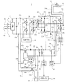
本発明の第1の実施形態のアーク溶接機用電源装置1は、図1に示すように、整流部2を有している。整流部2は、例えば三相交流電源端子4a、4b、4cから連動開閉スイッチ6を介して供給された三相交流電圧を整流するもので、例えば全波整流回路または半波整流回路を使用することができる。整流された三相交流電圧は、平滑手段、例えば平滑用コンデンサ8によって平滑される。この整流部2及び平滑用コンデンサ8によって直流電源部が構成されている。
The arc welder
この直流電源部からの直流が、第1の直流−交流変換器、例えばインバータ10の2つの入力端子10a、10bに供給される。入力端子10aが正極で、入力端子10bが負極である。インバータ10は、複数、例えば4個の半導体スイッチング素子、例えばIGBT14を例えばフルブリッジ形態に接続したものである。これらIGBT12は、制御回路16からの制御信号に応じてオン、オフ制御され、直流電源を交流電源に変換して、2つの出力端子10c、10dに出力する。
The direct current from the direct current power supply unit is supplied to two
インバータ10の2つの出力端子10c、10dに生成された交流は、絶縁手段、例えば変圧器20が有する1次巻線20pの両端間に供給される。変圧器20は、2次巻線20sも有しており、この2次巻線20sは、中間タップ20tを有している。2次巻線20sの両端間に、第1の交流−直流変換器、例えば整流回路22の2つの入力端子22a、22bが接続されている。整流回路22は、複数、例えば4つのダイオード24をブリッジ接続した全波整流回路で、その出力端子22c、22dは、リアクトル26a、26bを介して第2の直流−交流変換器、例えばスイッチング回路28の2つの入力端子28a、28bに接続されている。リアクトル26a、26bは同一の鉄心に巻回されたものである。入力端子28aが正極であり、入力端子28bが負極である。
The alternating current generated at the two
スイッチング回路28は、2つの入力端子28a、28b間に半導体スイッチング素子、例えばIGBT30a、30bのコレクタ−エミッタ導電路を直列に接続し、両IGBT30の接続点を一方の出力端子28cに接続し、変圧器20の2次巻線20sの中間タップ20tを他方の出力端子28dに接続したものである。出力端子28cが正極または負極であり、出力端子28cが中間タップ20tの基準電位である。IGBT30a、30bは、制御回路32からの制御信号によってIGBT30aがオンの時、IGBT30bがオフとなり、IGBT30aがオフの時、IGBT30bがオンであることを繰り返すように、制御されている。
In the switching
これら出力端子28c、28dは、1対のケーブル34a、34bを介して溶接負荷、例えば母材36とトーチ38とに接続されている。例えば、出力端子28cは、ケーブル34aを介して母材36に接続され、出力端子28dは、ケーブル34bを介してトーチ38に接続されている。
These
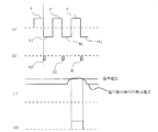
従って、連動開閉スイッチ6を閉じることによって、商用交流電源が整流回路2及び平滑用コンデンサ8によって直流電源に変換されると、この直流電源は、さらにインバータ10によって交流電源に変換され、変圧器20を介して整流回路22に供給され、ここで整流された後、リアクトル26a、26bを介してスイッチング回路28に供給される。IGBT30aがオンで、IGBT30bがオフの時、図2(a)に符号Pで示す正極性電圧が母材36及びトーチ38に印加されることが繰り返され、IGBT30aがオフで、IGBT30bがオンの時、図2(a)に符号N1で示す第1の負極性電圧が母材36及びトーチ38に印加されることが繰り返され、母材36とトーチ38間にアークが発生する。
Therefore, when the commercial AC power supply is converted into a DC power supply by the rectifier circuit 2 and the smoothing capacitor 8 by closing the interlocking open / close switch 6, this DC power supply is further converted into an AC power supply by the
図2(a)に示すように正極性電圧Pから負極性電圧Nに遷移するときに、アーク切れが発生しやすい。これを防止するために、第1の負極性電圧N1の印加と同期して同図(b)に示すように第2の負極性電圧N1を第1の負極性電圧Nに重畳することが行われている。第2の負極性電圧N1は、第1の負極性電圧Nと同期して重畳され、その発生期間は、第1の負極性電圧N1よりも短い期間である。 As shown in FIG. 2A, when the positive voltage P transitions to the negative voltage N, an arc break is likely to occur. In order to prevent this, the second negative voltage N1 is superimposed on the first negative voltage N in synchronization with the application of the first negative voltage N1, as shown in FIG. It has been broken. The second negative voltage N1 is superimposed in synchronization with the first negative voltage N, and the generation period thereof is shorter than the first negative voltage N1.
第2の負極性電圧N1を母材36とトーチ38に供給するために、重畳電源、例えば補助電源40が、このアーク溶接機用電源装置1には設けられている。補助電源40は、変圧器42を有し、その1次巻線42pは、半導体スイッチング素子、例えばIGBT44のコレクタ−エミッタ導電路に直列に接続されている。この直列回路は、補助電源40の入力端子40a、40bを介してインバータ10の入力端子10a、10bに接続されている。従って、IGBT44がオンの時、整流回路2及び平滑用コンデンサ8からなる直流電源部から直流電源が、1次巻線42pに供給される。変圧器42の2次巻線42sの一端には、整流手段、例えばダイオード46のアノードが接続されている。ダイオード46のカソードと2次巻線42sの他端との間に平滑用コンデンサ48と抵抗器50との並列回路が接続されている。IGBT44は、制御回路52からの制御信号に基づいてオン、オフを繰り返しており、これによって変圧器42の2次巻線42sに誘起された電圧がダイオード46によって整流され、平滑用コンデンサ48によって平滑される。
In order to supply the second negative voltage N <b> 1 to the
ダイオード46のカソードは、スイッチング素子、例えばIGBT54のコレクタ−エミッタ導電路と抵抗器56との直列回路を介して補助電源40の出力端子40cに接続されている。補助電源40の出力端子40dは、変圧器42の2次巻線42sの他端に接続されている。出力端子40cが正極性で、出力端子40dが負極性である。出力端子40cは、スイッチング回路28の出力端子28dに接続され、出力端子40dは、スイッチング回路28の入力端子28bに接続されている。IGBT54は、制御回路58からの制御信号に基づいてオン、オフ制御される。制御回路58は、IGBT30a、30bを制御する制御回路32と協働して、IGBT30bがオンになるのと同時にIGBT54をオンするように制御信号を発生する。これによって、図2(b)に示すように第2の負極性電圧N2を母材36とトーチ38との間に繰り返し印加する。なお、符号60で示すダイオードは、逆流防止用である。なお、IGBT54のコレクタには、逆流防止用ダイオード61を介してリアクトル26aによって平滑された整流回路22の出力も供給されている。
The cathode of the
出力端子28c、28dと母材36及びトーチ38とは、ケーブル34a、34bを介して接続されているが、母材36及びトーチ38とアーク溶接機用電源装置1とが離れた場所に設置されることがある。この場合、ケーブル34a、34bの長さが長くなり、そのインダクタンスが大きくなる。その結果、ケーブル34a、34bに誘起された電圧が大きくなり、出力端子28c、28d間の電圧が大きくなることがある。従来、このような場合、アーク溶接機用電源装置1を停止させていたが、これでは頻繁にアーク溶接機用電源装置1を停止させる必要があり、作業能率が低下する。
The
そこで、このアーク溶接機用電源装置1では、ケーブル34a、34bに誘起された電圧を低下させて、アーク溶接機用電源装置1が停止することを防止するために、ケーブル34a、34bに誘起された電圧をインバータ10の入力側に回生させている。
Therefore, in the arc
即ち、スイッチング回路28の入力端子28aは逆流阻止ダイオード61を介してIGBT54のコレクタとダイオード46のカソードの接続点に接続されており、この接続点が、回生回路63の入力端子63aに接続されている。また、補助電源40の出力端子40dに回生回路63の入力端子63bが接続されている。これら入力端子63a、63bは、絶縁手段、例えば絶縁変圧器64の1次巻線64pと半導体スイッチング素子、例えばIGBT66のコレクタ−エミッタ導電路との直列回路の両端に接続されている。IGBT66は、制御回路68の制御信号によってオン、オフ制御される。
That is, the
制御回路68は、スイッチング回路28の入力端子28a、28b間の電圧を検出している電圧検出器70が、入力端子28a、28b間の電圧が図2(c)に示すように予め定めた基準電圧を超えている期間、同図(d)に示すようにIGBT66をオンさせる。変圧器64は2次巻線64sを有している。2次巻線64sには、IGBT66のオンによって、電圧が誘起される。2次巻線64Sの一端は、ダイオード72を介して回生回路63の出力端子63cに接続され、2次巻線64sの他端は、回生回路63の出力端子63dに接続されている。ダイオード72は、2次巻線64側にアノードが位置し、出力端子63c側にカソードが位置するように2次巻線64の一端と出力端子63cとの間に接続されている。出力端子63cは正極性で、出力端子63dは負極性である。これら出力端子63cは、インバータ10の入力端子10aに接続され、出力端子63dはインバータ10の入力端子10bに接続されている。
The
変圧器64の2次巻線64sに誘起された電圧はダイオード72によって整流され、インバータ10の入力端子10a、10b間に印加される。即ち、回生動作が行われる。これによって、出力端子28c、28d間の電圧は低下し、ケーブル34a、34bが長いことに起因して、アーク溶接機用電源装置1が停止することを防止できるし、回生することによって省電力化を図ることができる。
The voltage induced in the secondary winding 64 s of the
本発明の第2の実施形態のアーク溶接機用電源装置1aを図3に示す。このアーク溶接機用電源装置1aは、第1の実施形態のアーク溶接機用電源装置1における補助電源40と回生回路63とを兼用した兼用回路400を設けた以外、第1の実施形態のアーク溶接機用電源装置1の構成と同一である。同一部分には同一符号を付して、その説明を省略する。
A power supply device 1a for an arc welder according to a second embodiment of the present invention is shown in FIG. The arc welder power supply device 1a is the same as the arc welder of the first embodiment except that the dual-
兼用回路400は、第1の実施形態のアーク溶接機用電源装置1の補助電源40において使用した変圧器42を、回生回路においても使用するように構成してある。変圧器42の1次巻線42pの両端は、インバータ80の2つの出力側に接続されている。即ち、インバータ80は、複数、例えば4つの半導体スイッチング素子、例えばIGBT82をブリッジ接続したもので、その2つの出力側に1次巻線42pの両端が接続されている。このインバータ80の2つの入力側が、兼用回路400の入出力端子400a、400bを兼用し、入出力端子400aがインバータ10の入力端子10aに接続され、入出力端子400bがインバータ10の入力端子10bに接続されている。各IGBT82は、制御回路83によってオン、オフ制御され、インバータ10の入力端子10a、10bから供給された直流を交流に変換して、変圧器42の1次巻線42pに供給する。
The shared
各IGBT82は、上述した各IGBT14、30a、30bでは説明を省略したが、IGBT82のコレクタ−エミッタ導電路には、ダイオード84が、逆並列に、即ちコレクタ側にカソードが、エミッタ側にアノードが位置する状態に、接続されている。これらダイオード84は、この実施形態では、ブリッジ回路からなる整流回路を構成しており、インバータ80の2つの出力側から交流が供給されると、これを整流して、インバータ10の入力端子10a、10bに供給する。従って、インバータ80は、双方向インバータとして機能する。
The description of each
このように、インバータ80において、IGBT82によって構成されたブリッジ回路と、IGBT82に逆並列接続されたダイオード84によって構成された整流回路とは、IGBT82のブリッジ回路の入力側が、ダイオード84によるブリッジ回路の整流回路の出力側となり、IGBT82のブリッジ回路の出力側が、ダイオード84によるブリッジ回路の整流回路の出力側となるように、並列に接続されている。
Thus, in the
変圧器42の2次巻線42sの両端は、インバータ86の2つの出力側に接続されている。即ち、インバータ86も、複数、例えば4つの半導体スイッチング素子、例えばIGBT88をブリッジ接続したもので、その2つの出力側に2次巻線42sの両端が接続されている。このインバータ86の2つの入力側の一方がIGBT54のコレクタ側に接続され、他方が兼用回路400の一方の出力端子400dに接続されている。他方の出力端子400cは、抵抗器56を介してIGBT54のエミッタに接続されている。各IGBT88も、制御回路83によってオン、オフ制御され、ダイオード61を介して供給されたスイッチング回路28の入力端子28a、28bから供給された直流を交流に変換して、変圧器42の2次巻線42sに供給する。制御回路83は、電圧検出器70が予め定めた基準電圧を超えていることを検出している期間、各IGBT88をオン、オフ制御する。
Both ends of the secondary winding 42 s of the
各IGBT88にそれぞれ逆並列に接続されたダイオード90も、ブリッジ回路の整流回路を構成し、変圧器42の2次巻線42sから供給された交流を直流に変換して、コンデンサ48及び抵抗器50の並列回路に供給する。インバータ86も、双方向インバータであって、IGBT88によって構成されたブリッジ回路と、IGBT88に逆並列接続されたダイオード90によって構成された整流回路とは、IGBT88のブリッジ回路の入力側が、ダイオード90によるブリッジ回路の整流回路の出力側となり、IGBT88のブリッジ回路の出力側が、ダイオード90によるブリッジ回路の整流回路の出力側となるように、並列に接続されている。
The
このアーク溶接機用電源装置1aでは、通常、兼用回路400を補助電源として使用しており、IGBT82のオン、オフ制御が行われている。これによって、変圧器42の1次巻線42pに交流が印加される。このとき、インバータ86の各IGBT88は全てオフで、変圧器42sに誘起された交流は、各ダイオード90によって整流され、コンデンサ48によって平滑され、IGBT54のコレクタ−エミッタ導電路とダイオード60との直列回路に供給される。以下、第1の実施形態と同様に制御回路58がスイッチング回路28のIGBT30a、30bを制御して、第2の負極性電圧を母材36とトーチ38とに印加する。
In this arc welder power supply device 1a, the shared
一方、電圧検出器70がスイッチング回路28の入力端子28a、28b間の電圧が第1の実施形態のアーク溶接機用電源装置1と同様に基準電圧を超えたことを検出したとき、制御回路83は、インバータ80の各IGBT82をオフとし、インバータ86の各IGBT88のオン、オフ制御を開始する。これによって、スイッチング回路28の入力端子28a、28b間の電圧が交流電圧に変換され、変圧器42の2次巻線42sに印加され、変圧器42の1次巻線42pに誘起された交流電圧が、インバータ80のダイオード84によって整流され、インバータ10の入力端子10a、10bに供給される。即ち、回生動作が行われる。
On the other hand, when the
このアーク溶接機用電源装置1aでは、補助電源と回生回路とを兼用回路400によって兼用しているので、使用する変圧器が、変圧器42のみであり、構成を簡略化することができる上に、アーク溶接機用電源装置1aを小型化することができる。
In this arc welder power supply device 1a, the auxiliary power supply and the regenerative circuit are shared by the shared
第1の実施形態では、スイッチング回路28の入力端子28a、28b間の電圧が基準電圧を超えている期間、IGBT66をオンさせたが、オン、オフを繰り返すようにすることもできる。また、第1及び第2の実施形態では、インバータ10は4つのIGBT14を使用したフルブリッジ構成としたが、2つのIGBTを使用したハーフブリッジ構成とすることもできる。また、第1の実施形態の補助電源40においてダイオード46のみで整流したが、4つのダイオードを使用したブリッジ構成の整流回路を使用することもできる。同様に回生回路63においてダイオード72に代えて、4つのダイオードを使用したブリッジ構成の整流回路を使用することもできる。また、第2の実施形態では、インバータ80、86は4つのIGBT82、84によるフルブリッジ構成のものとしたが、2つのIGBTを使用したハーフブリッジ構成のインバータを使用することもできる。但し、ダイオード84、90によるブリッジ回路による整流回路は、そのまま使用する。両実施形態では、スイッチング素子としてIGBTを使用したが、これに代えてMOSFETまたはバイポーラトランジスタを使用することもできる。
In the first embodiment, the
10 インバータ(第1の直流−交流変換器)
22 整流回路(第1の交流−直流変換器)
28 スイッチング回路(第2の直流−交流変換器)
34a 34b ケーブル
36 母材(溶接負荷)
40 回生回路
38 トーチ(溶接負荷)
10 Inverter (first DC-AC converter)
22 Rectifier circuit (first AC-DC converter)
28 Switching circuit (second DC-AC converter)
40
Claims (4)
第1の直流−交流変換器からの交流電源を直流電源に変換する第1の交流−直流変換器と、
正極性電圧と第1の負極性電圧とに交互に変化する交流電圧に、第1の交流−直流変換器の出力直流電圧を変換して、1対の出力端子に供給する第2の直流−交流変換器と、
前記1対の出力端子に接続され、前記第第2の直流―交流変換器の交流電圧を溶接負荷に供給する1対のケーブルと、
前記正極性電圧から前記第1の負極性電圧への移行時から前記第1の負極性電圧の期間よりも短い期間に亘って、第2の負極性電圧を前記溶接負荷に前記1対の出力端子及び前記1対のケーブルを介して供給する重畳電源と、
前記1対のケーブルに誘起された電圧に起因して前記重畳電源の電圧が予め定めた電圧を超えたとき、前記1対のケーブル間の電圧を前記第1の交流−直流変換器の入力側に回生する回生回路とを、
有するアーク溶接機用電源装置。 A first DC-AC converter for converting a DC power source into an AC power source;
A first AC-DC converter that converts AC power from the first DC-AC converter into DC power;
A second direct current − that is supplied to a pair of output terminals by converting the direct current output voltage of the first alternating current-direct current converter into an alternating voltage that alternately changes to a positive polarity voltage and a first negative polarity voltage. An AC converter,
A pair of cables connected to the pair of output terminals for supplying an AC voltage of the second DC-AC converter to a welding load;
The pair of outputs of the second negative voltage to the welding load for a period shorter than the period of the first negative voltage from the transition from the positive voltage to the first negative voltage. A superimposed power source supplied via a terminal and the pair of cables;
When the voltage of the superimposed power source exceeds a predetermined voltage due to the voltage induced in the pair of cables, the voltage between the pair of cables is input to the input side of the first AC-DC converter. A regenerative circuit that regenerates
A power supply device for an arc welding machine.
第1の直流−交流変換器からの交流電源を直流電源に変換する第1の交流−直流変換器と、
正極性電圧と第1の負極性電圧とに交互に変化する交流電圧に、第1の交流−直流変換器の出力直流電圧を変換して、1対のケーブルを介して溶接負荷に供給する第2の直流−交流変換器と、
前記正極性電圧から前記第1の負極性電圧への移行時から前記第1の負極性電圧の期間よりも短い期間に亘って、第2の負極性電圧を前記溶接負荷に前記1対のケーブルを介して供給する重畳電源と、
前記1対のケーブルに誘起された電圧に起因して前記重畳電源の電圧が予め定めた電圧を超えたとき、前記1対のケーブル間の電圧を前記第1の交流−直流変換器の入力側に回生する回生回路とを、
有し、
前記回生回路は、前記重畳電源を兼用するもので、前記第1の直流−交流変換器の入力側に接続された第1のインバータと、第1のインバータの出力が一方の巻線に供給される変圧器と、前記第2の交流−直流変換器と、この第2の交流−直流変換器と並列に接続された前記1対のケーブル間の電圧が供給され、その出力を前記変圧器の他方の巻線に供給する第2のインバータとを、有し、前記重畳電源を兼用する前記回生回路が、前記重畳電源として動作するとき、第1のインバータが動作し、前記回生回路として動作するとき、第2のインバータが動作するアーク溶接機用電源装置。 A first DC-AC converter for converting a DC power source into an AC power source;
A first AC-DC converter that converts AC power from the first DC-AC converter into DC power;
The output DC voltage of the first AC-DC converter is converted into an AC voltage that alternately changes to a positive polarity voltage and a first negative polarity voltage, and supplied to the welding load via a pair of cables. Two DC-AC converters;
The pair of cables is connected to the welding load with the second negative voltage over a period shorter than the period of the first negative voltage from the transition from the positive voltage to the first negative voltage. A superimposed power supply to be supplied via
When the voltage of the superimposed power source exceeds a predetermined voltage due to the voltage induced in the pair of cables, the voltage between the pair of cables is input to the input side of the first AC-DC converter. A regenerative circuit that regenerates
Have
The regenerative circuit also serves as the superimposed power source. The first inverter connected to the input side of the first DC-AC converter and the output of the first inverter are supplied to one winding. And a voltage between the pair of cables connected in parallel with the second AC-DC converter and the second AC-DC converter, and the output is supplied to the transformer. When the regenerative circuit that also serves as the superimposed power supply operates as the superimposed power supply, the first inverter operates and operates as the regenerative circuit. When the second inverter operates, the power supply for the arc welding machine.
前記第1のインバータの前記第1のスイッチング素子が動作すると共に、前記第2のインバータの前記第2のスイッチング素子がオフに制御されることにより、前記重畳電源を兼用する前記回生回路が、前記重畳電源として動作し、
前記1対のケーブルに誘起された電圧に起因して前記重畳電源の電圧が予め定めた電圧を超えたとき、前記第2のインバータの第2のスイッチング素子が動作すると共に、前記第1のインバータの前記第1のスイッチング素子がオフに制御されることにより、前記重畳電源を兼用する前記回生回路が、前記回生回路として動作するアーク溶接機用電源装置。 4. The power supply device for an arc welder according to claim 3, wherein the first inverter includes at least two sets of a first switching element and a first diode connected in antiparallel to the first switching element. The second inverter includes at least two sets of a second switching element and a second diode connected in antiparallel to the second switching element. A second bidirectional inverter,
When the first switching element of the first inverter operates and the second switching element of the second inverter is controlled to be turned off, the regenerative circuit that also serves as the superimposed power supply is Operates as a superimposed power supply,
When the voltage of the superimposed power source exceeds a predetermined voltage due to the voltage induced in the pair of cables, the second switching element of the second inverter operates and the first inverter When the first switching element is controlled to be turned off, the regenerative circuit that also serves as the superimposed power source operates as the regenerative circuit.
Priority Applications (1)
| Application Number | Priority Date | Filing Date | Title |
|---|---|---|---|
| JP2013211789A JP6203594B2 (en) | 2013-10-09 | 2013-10-09 | Power supply unit for arc welding machine |
Applications Claiming Priority (1)
| Application Number | Priority Date | Filing Date | Title |
|---|---|---|---|
| JP2013211789A JP6203594B2 (en) | 2013-10-09 | 2013-10-09 | Power supply unit for arc welding machine |
Publications (3)
| Publication Number | Publication Date |
|---|---|
| JP2015076988A JP2015076988A (en) | 2015-04-20 |
| JP2015076988A5 JP2015076988A5 (en) | 2016-09-23 |
| JP6203594B2 true JP6203594B2 (en) | 2017-09-27 |
Family
ID=53001454
Family Applications (1)
| Application Number | Title | Priority Date | Filing Date |
|---|---|---|---|
| JP2013211789A Active JP6203594B2 (en) | 2013-10-09 | 2013-10-09 | Power supply unit for arc welding machine |
Country Status (1)
| Country | Link |
|---|---|
| JP (1) | JP6203594B2 (en) |
Families Citing this family (3)
| Publication number | Priority date | Publication date | Assignee | Title |
|---|---|---|---|---|
| JP6661509B2 (en) * | 2016-10-04 | 2020-03-11 | 日立オートモティブシステムズ株式会社 | Control device and control method for brushless motor |
| EP3616823A1 (en) * | 2018-08-30 | 2020-03-04 | Fronius International GmbH | Method for compensating for interference of a welding current from another welding current source |
| EP3616822A1 (en) * | 2018-08-30 | 2020-03-04 | Fronius International GmbH | Method for determining an interfering coupling between welding current circuits of a welding installation |
Family Cites Families (8)
| Publication number | Priority date | Publication date | Assignee | Title |
|---|---|---|---|---|
| JPS63309373A (en) * | 1987-06-11 | 1988-12-16 | Hitachi Seiko Ltd | Arc welding source |
| JPH0241777A (en) * | 1988-07-29 | 1990-02-09 | Daihen Corp | Power unit for arc machining |
| JP2789222B2 (en) * | 1989-06-02 | 1998-08-20 | 株式会社日立製作所 | Power converter |
| JPH0533640U (en) * | 1991-10-09 | 1993-04-30 | 三菱電機株式会社 | Power regeneration device |
| JPH0796367A (en) * | 1993-09-28 | 1995-04-11 | Sansha Electric Mfg Co Ltd | Arc welding machine |
| JPH08107683A (en) * | 1994-10-03 | 1996-04-23 | Mitsubishi Electric Corp | Drive controller of motor and insulation type bidirectional dc voltage converting circuit |
| JP2007318893A (en) * | 2006-05-25 | 2007-12-06 | Ntt Data Ex Techno Corp | Uninterruptible power supply device, bidirectional power transfer circuit, and power supply system |
| US20110000900A1 (en) * | 2009-07-01 | 2011-01-06 | Lincoln Global, Inc. | Inverter output rectifier circuit |
-
2013
- 2013-10-09 JP JP2013211789A patent/JP6203594B2/en active Active
Also Published As
| Publication number | Publication date |
|---|---|
| JP2015076988A (en) | 2015-04-20 |
Similar Documents
| Publication | Publication Date | Title |
|---|---|---|
| US9065341B2 (en) | DC-DC converter | |
| Kummari et al. | An isolated high-frequency link microinverter operated with secondary-side modulation for efficiency improvement | |
| JP6172277B2 (en) | Bidirectional DC / DC converter | |
| KR0133163B1 (en) | Arc welder | |
| US9787199B2 (en) | Power conversion device to control power distribution of input power to multiple outputs | |
| JP2019104040A (en) | Coated electrode welding system and welding power supply device for coated electrode welding | |
| JP6203594B2 (en) | Power supply unit for arc welding machine | |
| JP2013074767A (en) | Dc/dc converter | |
| JP2009124859A (en) | Power supply device for arc apparatus | |
| JP5124186B2 (en) | Power supply device and power supply device for arc machining | |
| JP6467524B2 (en) | Power converter and railway vehicle | |
| JP5919750B2 (en) | Power supply | |
| JP3584686B2 (en) | Voltage source power conversion circuit | |
| JP5778533B2 (en) | Regenerative motor end surge voltage suppression device, motor drive system, and regenerative motor end surge voltage suppression method | |
| JPH05104247A (en) | Arc welding machine | |
| CN212811585U (en) | Energy bidirectional flow type AC-DC converter | |
| JP2017022827A (en) | Auxiliary power unit | |
| JP7106799B2 (en) | welding power supply | |
| CN106130379A (en) | Combination type high-current rectifier and active harmonics suppressing method thereof | |
| JP2010283919A (en) | Auxiliary power supply for vehicle | |
| JP5440113B2 (en) | AC-DC converter | |
| JP2016135062A (en) | Electric power conversion system | |
| CN215393069U (en) | Pilot arc circuit for AC/DC argon arc welding machine | |
| JP5996377B2 (en) | Power supply for arc welding | |
| Komeda et al. | Power decoupling control method for an isolated single-phase ac-to-dc converter based on high-frequency cycloconverter topology |
Legal Events
| Date | Code | Title | Description |
|---|---|---|---|
| A521 | Request for written amendment filed |
Free format text: JAPANESE INTERMEDIATE CODE: A523 Effective date: 20160805 |
|
| A621 | Written request for application examination |
Free format text: JAPANESE INTERMEDIATE CODE: A621 Effective date: 20160805 |
|
| A977 | Report on retrieval |
Free format text: JAPANESE INTERMEDIATE CODE: A971007 Effective date: 20170607 |
|
| A131 | Notification of reasons for refusal |
Free format text: JAPANESE INTERMEDIATE CODE: A131 Effective date: 20170613 |
|
| A521 | Request for written amendment filed |
Free format text: JAPANESE INTERMEDIATE CODE: A523 Effective date: 20170726 |
|
| TRDD | Decision of grant or rejection written | ||
| A01 | Written decision to grant a patent or to grant a registration (utility model) |
Free format text: JAPANESE INTERMEDIATE CODE: A01 Effective date: 20170829 |
|
| A61 | First payment of annual fees (during grant procedure) |
Free format text: JAPANESE INTERMEDIATE CODE: A61 Effective date: 20170830 |
|
| R150 | Certificate of patent or registration of utility model |
Ref document number: 6203594 Country of ref document: JP Free format text: JAPANESE INTERMEDIATE CODE: R150 |
|
| R250 | Receipt of annual fees |
Free format text: JAPANESE INTERMEDIATE CODE: R250 |
|
| R250 | Receipt of annual fees |
Free format text: JAPANESE INTERMEDIATE CODE: R250 |
|
| R250 | Receipt of annual fees |
Free format text: JAPANESE INTERMEDIATE CODE: R250 |
|
| R250 | Receipt of annual fees |
Free format text: JAPANESE INTERMEDIATE CODE: R250 |