JP6201829B2 - Input device - Google Patents
Input device Download PDFInfo
- Publication number
- JP6201829B2 JP6201829B2 JP2014047918A JP2014047918A JP6201829B2 JP 6201829 B2 JP6201829 B2 JP 6201829B2 JP 2014047918 A JP2014047918 A JP 2014047918A JP 2014047918 A JP2014047918 A JP 2014047918A JP 6201829 B2 JP6201829 B2 JP 6201829B2
- Authority
- JP
- Japan
- Prior art keywords
- touch plate
- claw
- input device
- view
- touch
- Prior art date
- Legal status (The legal status is an assumption and is not a legal conclusion. Google has not performed a legal analysis and makes no representation as to the accuracy of the status listed.)
- Active
Links
Images


Landscapes
- Position Input By Displaying (AREA)
Description
本発明は、入力装置に関する。 The present invention relates to an input device.
従来、電子機器に電気信号を発し、動作指令を与える装置として、スイッチ操作装置や、押釦装置が種々提案されている(例えば、特許文献1、特許文献2参照)。これらの装置は、釦やスイッチの正常な操作、安定した動作を実現できるとしている。 Conventionally, various switch operation devices and push button devices have been proposed as devices for issuing an electrical signal to an electronic device and giving an operation command (see, for example, Patent Document 1 and Patent Document 2). These devices are said to be able to realize normal operation and stable operation of buttons and switches.
昨今、ノート型パーソナルコンピュータ等の電子機器は、ディスプレイ上の矢印(カーソル)を移動させたり、クリックによる指令を行ったりする機能を有するいわゆるタッチパッドを備えることがある。タッチパッドは、タッチ板の表面をなぞることによって矢印を移動させ、タッチ板を押下してスイッチボタンを押すことによって指令を発する。このようなタッチ板に対して、特許文献1や特許文献2等に開示された装置を適用することができると考えられる。ところで、昨今の電子機器では、防滴や防水対策が求められている。このような要求に対し、特許文献1や特許文献2で開示された装置では、防滴、防水対策については、格別な配慮がなされていない。
In recent years, electronic devices such as notebook personal computers may include a so-called touch pad having a function of moving an arrow (cursor) on a display or giving a command by clicking. The touchpad moves the arrow by tracing the surface of the touch plate, and issues a command by pressing the touch plate and pressing a switch button. It is considered that the devices disclosed in Patent Document 1,
1つの側面では、本明細書開示の入力装置は、タッチパッドを形成するタッチ板の適切な位置を維持しつつ、防滴防水構造を実現することを課題とする。 In one aspect, it is an object of the input device disclosed in the present specification to realize a drip-proof waterproof structure while maintaining an appropriate position of a touch plate forming a touch pad.
本明細書開示の入力装置は、電子機器の入力部が備える筐体に設けられた凹部と、裏面側にタッチパッド基板が装着された状態で前記凹部内に収容されるタッチ板と、を備え、前記タッチ板は、奥側を前記筐体へ装着する装着部と、手前側を前記筐体に支持されるとともに、前記筐体から離間させる方向に付勢する弾性を有する第1爪とを備える。 An input device disclosed in the present specification includes a recess provided in a housing included in an input unit of an electronic device, and a touch plate accommodated in the recess with a touchpad substrate mounted on the back side. The touch plate includes a mounting portion that attaches the back side to the housing, and a first claw that is supported by the housing on the front side and has elasticity that urges the touch plate in a direction away from the housing. Prepare.
本明細書開示の入力装置によれば、タッチパッドを形成するタッチ板の適切な位置を維持しつつ、防滴防水構造を実現することを課題とする。 According to the input device disclosed in this specification, it is an object to realize a drip-proof waterproof structure while maintaining an appropriate position of a touch plate forming a touch pad.
以下、本発明の実施形態について、添付図面を参照しつつ説明する。ただし、図面中、各部の寸法、比率等は、実際のものと完全に一致するようには図示されていない場合がある。また、図面によっては、説明の都合上、実際には存在する構成要素が省略されていたり、寸法が実際よりも誇張されて描かれていたりする場合がある。なお、以下の説明において、図3(A)、(B)に示す方向を奥側及び手前側として説明する。 Hereinafter, embodiments of the present invention will be described with reference to the accompanying drawings. However, in the drawings, the dimensions, ratios, and the like of each part may not be shown so as to completely match the actual ones. Further, depending on the drawings, components that are actually present may be omitted for convenience of explanation, or dimensions may be exaggerated from the actual drawing. In the following description, the directions shown in FIGS. 3A and 3B are described as the back side and the near side.
(実施形態)
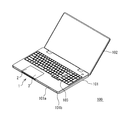
まず、図1を参照しつつ、本実施形態の入力装置1を備える電子機器100の概略構成について説明する。本実施形態では、電子機器100の一例として、ノート型(ラップトップ型)のパーソナルコンピュータを示している。電子機器100は、入力部101と、ディスプレイ部102を備える。入力部101は、アッパーカバー101aとアンダーカバー101bを有する筐体を備える。アッパーカバー101aには、入力装置1とキーボード部103が組み込まれている。入力装置1は、ディスプレイ部102に現れる矢印(カーソル)を移動させたり、クリックによる指令を行ったりする機能を有する。
(Embodiment)
First, a schematic configuration of an
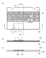
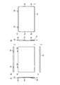
つぎに、図2乃至図10を参照しつつ、入力装置1について説明する。図2(A)は電子装置100の入力部101の平面図であり、図2(B)は電子装置100の入力部101の正面図である。図2(C)は図2(B)におけるC−C線断面図である。図3(A)通常状態時の図2(A)におけるA−A線断面図であり、図3(B)は通常状態時の図2(A)におけるB−B線断面図である。ここで、通常状態時とは、のちに説明するタッチ板3が押下されていない状態を意味する。図4はタッチパッド2を取り去った状態のアッパーカバー101aの一部分を示す説明図である。図5はアッパーカバー101aに設けられた凹部104の側壁部104cを示す説明図である。図6はタッチ板3の斜視図である。図7はタッチ板3の6面図であり、(A)平面図、(B)は背面図、(C)は正面図、(D)は右側面図、(E)は左側面図、(F)は底面図である。図8は図3(A)におけるX1部を拡大して示す説明図である。図9は図3(B)におけるX2部を拡大して示す説明図である。
Next, the input device 1 will be described with reference to FIGS. 2A is a plan view of the
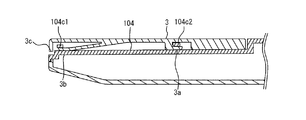
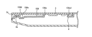
入力装置1は、電子機器100の入力部101が備える筐体、より具体的に、アッパーカバー101aに設けられた凹部104と、裏面側にタッチパッド基板4が装着された状態で凹部104内に収容されるタッチ板3を備える。タッチパッド基板4が装着されたタッチ板3は、タッチパッド2を形成する。タッチ板3は、第1爪3a、第2爪3b及びネジ止め部3dを備える。ここで、ネジ止め部3dは、タッチ板3の奥側を筐体(アッパーカバー101a)へ装着する装着部の一例である。第1爪は、タッチ板3の手前側を筐体(アッパーカバー101a)に支持されるとともに、筐体(アッパーカバー101a)から離間させる方向に付勢する弾性を有する。タッチ板3の手前側には、アンダーカバー101b方向に向かって延びるスカート部3cが設けられている。
The input device 1 includes a housing provided in the
凹部104は、タッチパッド2、より具体的には、タッチ板3の周囲からアッパーカバー101a側へ流れ込む水滴を排出するために、いわゆるバスタブ形状に成形された窪みである。すなわち、凹部104によって入力装置1の防滴防水が図られている。凹部104の中央部には、入力部101の内部と連通する連通孔104aが設けられている。連通孔104aは、入力部101内に設置されたマザーボード105とタッチパッド基板4とを接続するためのケーブル類が通過するために設けられている。連通孔104aの周囲には、立上り壁104a1が設けられている。立上り壁104aは連通孔104から水滴が入力部101内部へ浸入することを抑制するものである。
The
凹部104の奥側壁部104bには、タッチ板3に設けられたネジ止め部3dが装着されるネジ止め部104b1が設けられている。また、凹部104の側壁部104cには、後に詳説する第1係止部104c1及び第2係止部104c2が設けられている。第2係止部104c2は、第1係止部1041c1よりも奥側に設けられている。
A screwing
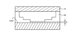
凹部104内の手前側には、ボタン押下部104dが設けられている。ボタン押下部104dの周囲には、排水凹部104eが設けられており、ボタン押下部104dが島状に突出した状態とされている。ボタン押下部104dは、タッチパッド基板4に設けられたスイッチボタン4aの位置に対応させて設けられており、タッチパッド2が押下されたときに、スイッチボタン4aがボタン押下部104dに接触し、押し込まれることによって、スイッチボタン4aが押下状態となる。
A
第1爪3aは、タッチ板3の手前側が浮き上がったり、落ち込んだりすることを抑制する。第1爪3aは、タッチ板3の手前側の浮き上がり及び落ち込みを抑制することができるものであれば、その設置箇所は問わないが、本実施形態の第1爪3aは、タッチ板3の両側部に設けられている。第1爪3aは、図10に拡大して示すように、スイッチボタン4aとボタン押下部104dとの所望の間隔Sを維持する機能を発揮する。このように、間隔Sが維持されることにより、誤動作が防止される。また、図11(A)、図11(B)に示すように、スイッチボタン4aを押下したときに、適度な操作感、換言すると適度なクリック感を得ることができる。図6や、図7(A)乃至図7(F)を参照すると、第1爪3aは、タッチ板3の下面側においてタッチ板3の奥側と手前側の間から枝分かれしている。そして、第1爪3aは、タッチ板3の前側に向かうにつれて、下方に延びている。第1爪3aは、このような形状を備えることにより、タッチ板3の手前側をアッパーカバー101aに設けられた凹部104の底部から離間させる方向に付勢する弾性力を強化することができる。第1爪3aは、タッチ板3の両側に設けられていることにより、タッチ板3の手前側の傾きを抑制することができる。また、左右でバランスが取れた安定した動作を実現することができる。このような第1爪3aは、図8に拡大して示すように凹部104の側壁部104cに設けられた第1係止部104c1に係止される。
The 1st nail |
第2爪3bは、ネジ止め部3dと第1爪3aとの間に設けられている。第2爪3bは、タッチ板3の側方が浮き上がることを抑制する。第1爪3aを備えることにより、タッチ板3の手前側の浮き上がりは抑制されるが、ネジ止め部3dと手前側との間で浮き上がる可能性がある。そこで、第2爪3bを装備することにより、タッチ板3の全周に亘って浮き上がりが抑制される。第2爪3bは、鉤状を有し、図8に拡大して示すように凹部104の側壁部104cに設けられた第2係止部104c2に係止される。
The
ここで、図12、図13を参照しつつ、本実施形態の入力装置の効果について説明する。図12(A)は第1比較例のタッチ板51の平面図であり、図12(B)は第1比較例のタッチ板51の側面図である。図13は第2比較例の入力装置60の一部断面図である。
Here, the effects of the input device of the present embodiment will be described with reference to FIGS. 12 and 13. 12A is a plan view of the
タッチ板3は、奥側で支持されることにより、奥側を支点とした押下動作が許容されるが、奥側から離れた手前側が沈み込むことが考えられる。このようなタッチ板3の手前側の沈み込みは、誤動作の原因や、操作感の低減の原因となる。第1比較例のタッチ板51は、奥側に回転軸部51aを備えるとともに、タッチ板51手前側の沈み込みを抑制するために、手前側に脚部52bを備える。脚部52bは、タッチ板51の側方に延びるとともに、弾性を発揮しやすい形状を備えることにより、タッチ板51の手前側を持ち上げる構成となっている。これにより、矢示53で示す押下方向へ押した時の操作感も向上する。しかしながら、脚部52bが側方に突出した形状となるため、本実施例が備える凹部104のような防滴防水対策がなされたアッパーカバー101aには適用しにくい。すなわち、脚部52bが凹部104の外側まで延びるため、防滴性、防水性を確保しにくい。また、タッチ板の材料として金属や、ガラス入り樹脂等を選定することにより、タッチ板の剛性を高め、手前側の撓みを抑制することも考えられるが、重量が増加してしまう。タッチパッドとアッパーカバーとの間にクッション素材を配置することも考えられるが、防滴性を考慮すると、クッション素材が吸水し、反発力が低下する可能性がある。
Since the
図13に示す第2比較例の入力装置60は、タッチ板61の手前側にスカート部61cを備え、奥側にネジ止め部61dを備え、ネジ止め部61dをネジ62で固定しただけの構成である。このような入力装置60のアッパーカバー63a及びアンダーカバー63bは、本実施例の入力装置1と同様の構成とすることができる。すなわち、防滴防水対策として、凹部を設けることができる。しかしながら、タッチ板61の手前側を適切に支持する部材を備えないため、ネジ止め部61dを支点としてタッチ板61に過大な力が加わることが考えられる。また、スカート部61cがアッパーカバー63aの前面に露出しており、タッチ板61が持ち上がってしまうことが考えられる。
The
これらの比較例に対し、本実施形態の入力装置1は、タッチパッド2を形成するタッチ板3の持ち上がりや落ち込みを抑制することで、タッチ板3の適切な位置を維持しつつ、防滴防水構造を実現することができる。
In contrast to these comparative examples, the input device 1 of the present embodiment suppresses the lifting and dropping of the
以上本発明の好ましい実施形態について詳述したが、本発明は係る特定の実施形態に限定されるものではなく、特許請求の範囲に記載された本発明の要旨の範囲内において、種々の変形、変更が可能である。 Although the preferred embodiment of the present invention has been described in detail above, the present invention is not limited to the specific embodiment, and various modifications, within the scope of the gist of the present invention described in the claims, It can be changed.
1 入力装置
2 タッチパッド
3 タッチ板
3a 第1爪
3b 第2爪
3c スカート部
3d ネジ止め部
4 タッチパッド基板
4a スイッチボタン
100 電子機器
101 入力部
101a アッパーカバー
101b アンダーカバー
102 ディスプレイ部
103 キーボード部
104 凹部
104a 連通孔
104a1 立上り壁
104b 奥側壁部
104b1 ネジ止め部
104c 側壁部
104c1 第1係止部
104c2 第2係止部
104d ボタン押下部
104e 排水凹部
105 マザーボード
DESCRIPTION OF SYMBOLS 1
Claims (4)
裏面側にタッチパッド基板が装着された状態で前記凹部内に収容されるタッチ板と、を備え、
前記タッチ板は、奥側を前記筐体へ装着する装着部と、手前側を前記筐体に支持されるとともに、前記筐体から離間させる方向に付勢する弾性を有する第1爪とを備えた入力装置。 A recess provided in a housing of the input unit of the electronic device;
A touch plate housed in the recess with the touchpad substrate mounted on the back side,
The touch plate includes a mounting portion that attaches the back side to the housing, and a first claw that has a front side supported by the housing and elastically biased in a direction away from the housing. Input device.
Priority Applications (1)
| Application Number | Priority Date | Filing Date | Title |
|---|---|---|---|
| JP2014047918A JP6201829B2 (en) | 2014-03-11 | 2014-03-11 | Input device |
Applications Claiming Priority (1)
| Application Number | Priority Date | Filing Date | Title |
|---|---|---|---|
| JP2014047918A JP6201829B2 (en) | 2014-03-11 | 2014-03-11 | Input device |
Publications (2)
| Publication Number | Publication Date |
|---|---|
| JP2015172822A JP2015172822A (en) | 2015-10-01 |
| JP6201829B2 true JP6201829B2 (en) | 2017-09-27 |
Family
ID=54260115
Family Applications (1)
| Application Number | Title | Priority Date | Filing Date |
|---|---|---|---|
| JP2014047918A Active JP6201829B2 (en) | 2014-03-11 | 2014-03-11 | Input device |
Country Status (1)
| Country | Link |
|---|---|
| JP (1) | JP6201829B2 (en) |
Family Cites Families (7)
| Publication number | Priority date | Publication date | Assignee | Title |
|---|---|---|---|---|
| JP4653586B2 (en) * | 2005-07-29 | 2011-03-16 | 株式会社東芝 | Electronics |
| JP4729433B2 (en) * | 2006-05-10 | 2011-07-20 | アルプス電気株式会社 | Input device |
| TWM374101U (en) * | 2009-10-05 | 2010-02-11 | Quanta Comp Inc | Touchpad module assembly structure |
| TW201229845A (en) * | 2011-01-14 | 2012-07-16 | Hon Hai Prec Ind Co Ltd | Touch control device and an electronic apparatus using the same |
| JP5606401B2 (en) * | 2011-06-23 | 2014-10-15 | アルプス電気株式会社 | Input device with movable touchpad |
| JP2014085941A (en) * | 2012-10-25 | 2014-05-12 | Toshiba Corp | Electronic apparatus |
| JP3186414U (en) * | 2013-07-24 | 2013-10-03 | アルプス電気株式会社 | Touchpad input device |
-
2014
- 2014-03-11 JP JP2014047918A patent/JP6201829B2/en active Active
Also Published As
| Publication number | Publication date |
|---|---|
| JP2015172822A (en) | 2015-10-01 |
Similar Documents
| Publication | Publication Date | Title |
|---|---|---|
| US9214295B2 (en) | Key structure | |
| JP2007087945A (en) | Multi-directional button and laptop pc using the same | |
| JP5750127B2 (en) | Pointing device, keyboard assembly and portable computer. | |
| JP4751470B2 (en) | Electronics | |
| TW201229845A (en) | Touch control device and an electronic apparatus using the same | |
| JP5968955B2 (en) | Input device and electronic device | |
| JP2012190453A (en) | Touch type input device and electronic device with touch type input device | |
| US20150022960A1 (en) | Computer assembly incorporating coupling within pantograph | |
| US9418798B2 (en) | Keyboard | |
| CN102810022A (en) | Touch device and electronic equipment with same | |
| EP2889734B1 (en) | Coordinate input device | |
| US9959990B1 (en) | Keyboard device | |
| TWI656551B (en) | Button device | |
| JP6201829B2 (en) | Input device | |
| JP6550187B2 (en) | Stand-alone input device | |
| US9105425B2 (en) | Electronic apparatus | |
| US10777372B2 (en) | Touchpad module and computing device using same | |
| US6713699B2 (en) | Key switch stabilizer mechanism | |
| CN201348960Y (en) | Keyboard | |
| US20200159346A1 (en) | Touchpad module and computing device using same | |
| JP5417460B2 (en) | Input reception unit and electronic equipment | |
| JP4865055B2 (en) | Electronics | |
| US20170338062A1 (en) | Slim key structure | |
| JP2016081393A (en) | Keyboard device and electronic apparatus | |
| US10020138B1 (en) | Keyboard device |
Legal Events
| Date | Code | Title | Description |
|---|---|---|---|
| A621 | Written request for application examination |
Free format text: JAPANESE INTERMEDIATE CODE: A621 Effective date: 20161102 |
|
| TRDD | Decision of grant or rejection written | ||
| A977 | Report on retrieval |
Free format text: JAPANESE INTERMEDIATE CODE: A971007 Effective date: 20170726 |
|
| A01 | Written decision to grant a patent or to grant a registration (utility model) |
Free format text: JAPANESE INTERMEDIATE CODE: A01 Effective date: 20170801 |
|
| A61 | First payment of annual fees (during grant procedure) |
Free format text: JAPANESE INTERMEDIATE CODE: A61 Effective date: 20170814 |
|
| R150 | Certificate of patent or registration of utility model |
Ref document number: 6201829 Country of ref document: JP Free format text: JAPANESE INTERMEDIATE CODE: R150 |
|
| S111 | Request for change of ownership or part of ownership |
Free format text: JAPANESE INTERMEDIATE CODE: R313113 |
|
| R350 | Written notification of registration of transfer |
Free format text: JAPANESE INTERMEDIATE CODE: R350 |
|
| R250 | Receipt of annual fees |
Free format text: JAPANESE INTERMEDIATE CODE: R250 |