JP6198484B2 - Method and apparatus for reframing an image of a video sequence - Google Patents
Method and apparatus for reframing an image of a video sequence Download PDFInfo
- Publication number
- JP6198484B2 JP6198484B2 JP2013136263A JP2013136263A JP6198484B2 JP 6198484 B2 JP6198484 B2 JP 6198484B2 JP 2013136263 A JP2013136263 A JP 2013136263A JP 2013136263 A JP2013136263 A JP 2013136263A JP 6198484 B2 JP6198484 B2 JP 6198484B2
- Authority
- JP
- Japan
- Prior art keywords
- bounding box
- determined
- sub
- determining
- image
- Prior art date
- Legal status (The legal status is an assumption and is not a legal conclusion. Google has not performed a legal analysis and makes no representation as to the accuracy of the status listed.)
- Expired - Fee Related
Links
- 238000000034 method Methods 0.000 title claims description 54
- 238000005070 sampling Methods 0.000 claims description 20
- 230000002123 temporal effect Effects 0.000 claims description 18
- 230000008569 process Effects 0.000 claims description 14
- 230000008859 change Effects 0.000 claims description 12
- 238000001514 detection method Methods 0.000 claims description 9
- 238000010191 image analysis Methods 0.000 claims description 7
- 238000004364 calculation method Methods 0.000 description 7
- 238000010586 diagram Methods 0.000 description 3
- 102100037812 Medium-wave-sensitive opsin 1 Human genes 0.000 description 2
- 230000006978 adaptation Effects 0.000 description 2
- 230000008901 benefit Effects 0.000 description 2
- 239000000284 extract Substances 0.000 description 2
- 230000000007 visual effect Effects 0.000 description 2
- 230000000295 complement effect Effects 0.000 description 1
- 230000007423 decrease Effects 0.000 description 1
- 230000003247 decreasing effect Effects 0.000 description 1
- 230000001419 dependent effect Effects 0.000 description 1
- 230000000694 effects Effects 0.000 description 1
- 230000007613 environmental effect Effects 0.000 description 1
- 238000000605 extraction Methods 0.000 description 1
- 238000001914 filtration Methods 0.000 description 1
- 238000009432 framing Methods 0.000 description 1
- 238000009499 grossing Methods 0.000 description 1
- 230000006872 improvement Effects 0.000 description 1
- 230000000670 limiting effect Effects 0.000 description 1
- 238000012986 modification Methods 0.000 description 1
- 230000004048 modification Effects 0.000 description 1
- 238000007781 pre-processing Methods 0.000 description 1
- 230000008707 rearrangement Effects 0.000 description 1
- 230000003068 static effect Effects 0.000 description 1
- 238000006467 substitution reaction Methods 0.000 description 1
Images


Classifications
-
- G06T3/04—
-
- G—PHYSICS
- G06—COMPUTING; CALCULATING OR COUNTING
- G06T—IMAGE DATA PROCESSING OR GENERATION, IN GENERAL
- G06T1/00—General purpose image data processing
-
- H—ELECTRICITY
- H04—ELECTRIC COMMUNICATION TECHNIQUE
- H04N—PICTORIAL COMMUNICATION, e.g. TELEVISION
- H04N5/00—Details of television systems
- H04N5/14—Picture signal circuitry for video frequency region
-
- H—ELECTRICITY
- H04—ELECTRIC COMMUNICATION TECHNIQUE
- H04N—PICTORIAL COMMUNICATION, e.g. TELEVISION
- H04N19/00—Methods or arrangements for coding, decoding, compressing or decompressing digital video signals
Description
本発明は、ビデオシーケンスのイメージを処理する方法及び装置に関し、特にビデオシーケンスのイメージをリフレーミングする方法及び装置に関する。 The present invention relates to a method and apparatus for processing an image of a video sequence, and more particularly to a method and apparatus for reframing an image of a video sequence.
EP1956550Aなどから知られるようなリフレーミングアプリケーションは、まずビデオシーケンスのサブパートをそれのコンテンツに基づきクロップ処理するよう設計されている。クロップ処理後、各ビデオイメージのリフレーミングされた部分のみが可視的なままにされる。リフレーミングアプリケーションは、視覚的注意モデル及び専用のリフレーミングアルゴリズムに関する。視覚的注意モデルは顕著性マップを生成し、リフレーミングアルゴリズムは当該顕著性マップに基づきクロップ処理ウィンドウを外挿する。このクロップ処理ウィンドウは、ビデオコンテンツに応じて位置及びサイズに関して可変的である。リフレーミングアルゴリズムは、符号化又は復号化処理について相補的である。利用ケースに応じて、リフレーミングアプリケーションは異なって利用されてもよい。例えば、リフレーミングアプリケーションは、モバイルビデオ符号化前の前処理として利用可能である。他の具体例では、リフレーミングアプリケーションは、ビデオ復号化の直後に実行される。 A reframing application such as that known from EP 1956550A is designed to first crop a sub-part of a video sequence based on its content. After cropping, only the reframed portion of each video image remains visible. The reframing application relates to a visual attention model and a dedicated reframing algorithm. The visual attention model generates a saliency map, and the reframing algorithm extrapolates the cropping window based on the saliency map. This cropping window is variable in position and size depending on the video content. The reframing algorithm is complementary for the encoding or decoding process. Depending on the use case, the reframing application may be used differently. For example, the reframing application can be used as pre-processing before mobile video encoding. In other implementations, the reframing application is executed immediately after video decoding.
ビデオコンテンツに基づきリフレーミングパラメータを自動調整するのに利用可能な先進的又は自動的な手段が現在ないという問題がある。 There is a problem that there are currently no advanced or automatic means available to automatically adjust the reframing parameters based on the video content.
本発明は、ビデオソースデータを復号化する際に利用可能な情報を活用することによって、リフレーミングアプリケーションの設定又は入力パラメータを自動調整することを可能にする。復号化されたビデオシーケンスのための設定又は入力パラメータを自動調整するための開示される手段は、以前に復号化されたシーケンスの性質を利用する。 The present invention makes it possible to automatically adjust reframing application settings or input parameters by leveraging information available when decoding video source data. The disclosed means for automatically adjusting settings or input parameters for a decoded video sequence takes advantage of the nature of the previously decoded sequence.
本発明によると、ビデオシーケンスのイメージを処理する方法は、ビデオシーケンスのパラメータ、ビデオシーケンスの前に復号化されたGOP(Group Of Picture)のパラメータ及びユーザ設定を決定するステップと、決定されたパラメータに従ってクロップ処理される部分を決定するステップと、表示のため決定された部分をクロップ処理するステップとを有する。 According to the present invention, a method of processing an image of a video sequence includes determining video sequence parameters, GOP (Group Of Picture) parameters decoded before the video sequence, and user settings; And determining a portion to be cropped in accordance with, and cropping the portion determined for display.
GOPサイズ、時間サブサンプリングファクタ、最小及び最大ズームファクタ又は境界ボックス速度などのビデオシーケンスの各種パラメータが決定及び利用可能である。これらのパラメータは、別々に利用されるか、又は組み合わせ可能である。例えば、一実施例では、決定及び利用されたパラメータは、(上述したパラメータから)境界ボックス速度のみを有する。 Various parameters of the video sequence such as GOP size, temporal sub-sampling factor, minimum and maximum zoom factor or bounding box speed can be determined and used. These parameters can be used separately or combined. For example, in one embodiment, the parameters determined and used have only the bounding box velocity (from the parameters described above).
一実施例では、決定及び利用されたパラメータは最小及び最大ズームファクタを有する。 In one embodiment, the determined and utilized parameters have minimum and maximum zoom factors.
一実施例では、決定及び利用されたパラメータは、GOPサイズ、時間サブサンプリングファクタ、最小及び最大ズームファクタ又は境界ボックス速度を有する。 In one embodiment, the parameters determined and utilized include GOP size, temporal subsampling factor, minimum and maximum zoom factor, or bounding box speed.
本発明の一実施例では、ビデオシーケンスのイメージを処理する方法は、前のイメージにおいてリフレーミングウィンドウに含めるための前のイメージの最も顕著な部分であるピクセルのサブエリア又はサブセットを決定するステップと、当該ピクセルのサブエリア又はサブセットの周辺の第1境界ボックスを決定するステップと、現在のイメージにおいてリフレーミングウィンドウに含めるための現在のイメージの最も顕著な部分であるピクセルのサブエリア又はサブセットと、当該エリアの周辺の第2境界ボックスとを決定するステップと、連続するイメージの間で境界ボックスを移動するための最大境界ボックス速度を決定するステップと、第1及び第2境界ボックスと境界ボックスの決定された最大速度から新たな境界ボックスを決定するステップと、現在のイメージにおいて表示のために決定された新たな境界ボックスに従ってサブエリアをクロップ処理するステップとを有する。 In one embodiment of the present invention, a method of processing an image of a video sequence includes determining a sub-area or subset of pixels that are the most prominent portion of the previous image for inclusion in the reframing window in the previous image. Determining a first bounding box around the sub-area or subset of the pixel; and a sub-area or subset of the pixel that is the most prominent part of the current image for inclusion in the reframing window in the current image; Determining a second bounding box around the area; determining a maximum bounding box speed for moving the bounding box between successive images; and first and second bounding boxes and bounding boxes A new bounding box is determined from the determined maximum speed The method comprising, a step of the sub-area to cropping process in accordance with the new bounding box is determined for display in the current image.
最大境界ボックス速度は、ビデオシーケンスの前に復号化されたGOPのパラメータから決定されてもよい。最大境界ボックス速度はまた、レジスタ又はストレージから抽出可能な所定値であってもよく、それはまたビデオシーケンスの前に復号化されたGOPについて有効である。 The maximum bounding box speed may be determined from the parameters of the GOP decoded before the video sequence. The maximum bounding box rate may also be a predetermined value that can be extracted from a register or storage, which is also valid for GOPs decoded before the video sequence.
上記方法を利用する装置は、ビデオシーケンスのパラメータを決定し、ビデオシーケンスの前に復号化されたGOP(Group Of Picture)のパラメータを決定し、ユーザ設定(ユーザインタフェース手段など)を決定するイメージ解析手段と、決定されたパラメータに従ってクロップ処理される部分を決定し、表示のため決定された部分をクロップ処理するイメージ処理手段とを有する。ビデオシーケンスの各種パラメータが、上述されるように、個別に又は組み合わせて決定及び利用可能である。 The apparatus using the above method determines the parameters of the video sequence, determines the parameters of the GOP (Group Of Picture) decoded before the video sequence, and determines the user settings (such as user interface means) image analysis Means and image processing means for determining a portion to be cropped according to the determined parameter and cropping the portion determined for display. Various parameters of the video sequence can be determined and used individually or in combination as described above.
本発明の一実施例では、ビデオシーケンスのイメージを処理する装置は、前のイメージにおいてリフレーミングウィンドウに含めるため前のイメージの最も顕著な部分であるピクセルのサブエリア又はサブセットを決定する手段と、当該ピクセルのサブエリア又はサブセットの周辺の第1境界ボックスを決定する手段と、現在のイメージにおいてリフレーミングウィンドウに含めるための現在のイメージの最も顕著な部分であるピクセルのサブエリア又はサブセットと当該エリアの周辺の第2境界ボックスとを決定する手段と、ビデオシーケンスの前に復号化されたGOPのパラメータから、連続するイメージの間で境界ボックスを移動するための最大境界ボックス速度を決定する手段と、第1及び第2境界ボックスと境界ボックスの決定された最大速度とから新たな境界ボックスを決定する手段と、現在のイメージにおいて表示のため決定された新たな境界ボックスに従ってサブエリアをクロップ処理する手段とを有する。 In one embodiment of the present invention, an apparatus for processing an image of a video sequence determines means for determining a sub-area or subset of pixels that are the most prominent portion of a previous image for inclusion in a reframing window in the previous image; Means for determining a first bounding box around the sub-area or subset of the pixel, and the sub-area or subset of the pixel that is the most prominent part of the current image for inclusion in the reframing window in the current image and the area Means for determining a second bounding box around the image, and means for determining a maximum bounding box velocity for moving the bounding box between successive images from parameters of the GOP decoded before the video sequence; , First and second bounding box and bounding box determined It has been a means for determining a new bounding box and a maximum speed, and means for the sub-area to cropping process in accordance with the new bounding box is determined for display in the current image.
一態様では、本発明は、コンピュータに上述されるような方法を実行させるための実行可能な命令を格納したコンピュータ可読媒体に関する。一実施例では、コンピュータは、ビデオシーケンスのイメージを処理する方法であって、ビデオシーケンスのパラメータを決定するステップと、ビデオシーケンスの前に復号化されたGOPのパラメータを決定するステップと、ユーザ設定を決定するステップと、決定されたパラメータに従ってクロップ処理される部分を決定するステップと、表示のため決定された部分をクロップ処理するステップとを有する方法を実行する。 In one aspect, the invention relates to a computer readable medium having stored thereon executable instructions for causing a computer to perform a method as described above. In one embodiment, a computer is a method of processing an image of a video sequence, the step of determining video sequence parameters, the step of determining parameters of a GOP decoded before the video sequence, and user settings Performing a method comprising: determining a portion to be cropped according to the determined parameter; and cropping the portion determined for display.
本発明の効果的な実施例は、従属形式の請求項、以下の説明及び図面に開示される。 Advantageous embodiments of the invention are disclosed in the dependent claims, the following description and the drawings.
本発明による、ビデオソースデータを復号化する際に利用可能な情報を活用することによって、リフレーミングアプリケーションの設定又は入力パラメータを自動調整することが可能になる。 By utilizing the information available when decoding video source data according to the present invention, it is possible to automatically adjust the settings or input parameters of the reframing application.
図1は、自動リフレーミングユニットARを備えたビデオデコーダDECの構成を示す。デコーダDECは、符号化入力ビデオシーケンス11を受信し、それを復号化して復号化ビデオシーケンス12を取得する。パラメータ抽出手段PEは、復号化ビデオシーケンス及び/又はデコーダ設定13からパラメータ及び/又はリフレーミング設定14を抽出する。自動リフレーミングユニットARは、復号化ビデオシーケンス12及び抽出されたパラメータ及び/又はリフレーミング設定14から、リフレーミング(すなわち、クロップ処理された)ビデオシーケンス16を生成する。
FIG. 1 shows a configuration of a video decoder DEC provided with an automatic reframing unit AR. The decoder DEC receives the encoded
リフレーミングアプリケーションは、本発明によると符号化ストリーム又は復号化処理から自動調整されたある個数の設定Sを有する。一実施例では、当該設定は、バッファサイズ、時間サブサンプリングファクタ、2つのズームファクタzmin及びzmax、並びに境界ボックス速度を有する。これらの設定s1,s2,s3,s4は、以下に記述される。 The reframing application has a certain number of settings S automatically adjusted from the encoded stream or the decoding process according to the invention. In one embodiment, the settings include buffer size, temporal sub-sampling factor, two zoom factors z min and z max , and bounding box speed. These settings s 1 , s 2 , s 3 , s 4 are described below.

時間サブサンプリングファクタ(s2)は、リフレーミング処理が適用されるフレーム数を制限するのに利用され、これにより、例えば、ssにおける1フレーム又はs2個のフレームからの1フレームのみにリフレーミング処理を適用するなど、アプリケーションの計算複雑さを低減及び制御することが可能である。一実施例では、可能な時間サブサンプリングファクタ/モードは、GOPの長さ及びs2に応じて“フルモード”(すべてのフレーム)、“中間モード”(IフレームとPフレームのみ)及び“ライトモード”(Iフレームのみ)である。 Temporal sub-sampling factor (s 2) is used to limit the number of frames reframing process is applied, thereby, for example, Li only one frame from one frame or s 2 frames in s s It is possible to reduce and control the computational complexity of the application, such as applying a framing process. In one embodiment, possible temporal subsampling factors / modes are “full mode” (all frames), “intermediate mode” (I and P frames only) and “write” depending on the length of the GOP and s 2. Mode "(I frame only).
ズームファクタ(s3=(zmin,zmax))は、クロップ処理ウィンドウが境界間で経時的に変更しうる境界を規定する。この制限は、クロップ処理ウィンドウのサイズを変更する。ユーザは、大きすぎる又は小さすぎるズーム効果を回避するため、当該特徴を設定してもよい。一実施例では、シーンカット後の最初のピクチャにおいて、MBコストマップが、最も重要なブロックを検出するため生成される。その後、MBコストマップが、ズームファクタを決定するため利用される。 The zoom factor (s 3 = (z min , z max )) defines the boundaries that the cropping window can change between boundaries over time. This restriction changes the size of the crop processing window. The user may set the feature to avoid zoom effects that are too large or too small. In one embodiment, in the first picture after a scene cut, an MB cost map is generated to detect the most important blocks. The MB cost map is then used to determine the zoom factor.
境界ボックス速度(s4)は、クロップ処理ウィンドウがピクチャ内で移動可能な速度である。一実施例では、境界ボックスは、リフレーミングウィンドウに含まれるべき最も顕著であると選択されるサブエリア又はピクセルのサブセットを表す。許容される速度はイメージコンテンツに依存し、すなわち、それは、以降のイメージのイントラ予測されたMB間の相関がかなり低いか、かなり高いときに低い値に制限される。高い相関は、静的イメージ又は少ない動きを意味し、安定的な境界ボックス位置が好ましく、低い相関は、シーン変更(すなわち、新たな“ショット”)を意味し、それは、境界ボックスシフトによって補償できないため、アルゴリズムを酷使することになる。従って、境界ボックス速度s4は、コンテンツに依存してカメラの自然なカメラの動きにより良好に適合するようにシーケンスに対して適応化されてもよい。一実施例では、Kalmanフィルタは、フィルタリングのための境界ボックス座標に適用され、境界ボックス速度は、Kalmanフィルタに投入されるノイズファクタである。 The bounding box speed (s 4 ) is the speed at which the crop processing window can move within the picture. In one embodiment, the bounding box represents a sub-area or a subset of pixels that are selected to be most prominent to be included in the reframing window. The allowed speed depends on the image content, i.e. it is limited to a low value when the correlation between intra-predicted MBs of subsequent images is quite low or very high. High correlation means static image or low motion, stable bounding box position is preferred, low correlation means scene change (ie new “shot”), which cannot be compensated by bounding box shift For this reason, the algorithm is abused. Thus, the bounding box velocity s 4 may be adapted to the sequence to better match the natural camera movement of the camera depending on the content. In one embodiment, the Kalman filter is applied to the bounding box coordinates for filtering, and the bounding box velocity is a noise factor that is input to the Kalman filter.
図2は、ビデオシーケンスのイメージを処理するための方法のフローチャートである。本方法は、ビデオシーケンスのパラメータ、ビデオシーケンスの以前に復号化されたGOP(Group Of Picture)のパラメータ及びユーザ設定を決定するステップ21と、決定されたパラメータに従ってクロップ処理される部分を決定するステップ22と、決定された部分を表示のためクロップ処理するステップ23とを有する。
FIG. 2 is a flowchart of a method for processing an image of a video sequence. The method includes
一実施例では、復号化パラメータは以下のように決定される。 In one embodiment, the decoding parameters are determined as follows:
バッファサイズs1は、GOPサイズ(Gsize)に従って調整される。原理的には、当該バッファサイズが小さなGOPについて低減され、フルバッファSizemaxがあるリミットを超過したGOPサイズについて利用される。GOPサイズは、デコーダDECがストレージから抽出するか、又は符号化ビットストリームから抽出してもよい所定のパラメータである。以下のルールが適用されてもよい。 The buffer size s 1 is adjusted according to the GOP size (Gsize). In principle, the buffer size is reduced for small GOPs and is used for GOP sizes where the full buffer Size max exceeds a certain limit. The GOP size is a predetermined parameter that the decoder DEC may extract from the storage or from the encoded bitstream. The following rules may apply:
時間サブサンプリングファクタs2は、GOPサイズ及びスキームに従って設定されてもよい。その考え方は、少なくともIフレームに対するリフレーミング処理(及びそのときの顕著性マップ)の計算を維持することであり、これは、それらが最も高いクオリティを有し、シーンの始め(すなわち、シーンカットの直後)にある可能性が高いためである。このとき、Pフレームは、処理対象としてあまり関心はない。最後に、時間サブサンプリングによりフレームを削除する必要がある場合、Bフレームは省略されるべき最初のフレームになるであろう。 The temporal subsampling factor s 2 may be set according to the GOP size and scheme. The idea is to maintain at least the computation of the reframing process (and the saliency map at that time) for I frames, which has the highest quality and is the beginning of the scene (ie the scene cut This is because there is a high possibility that At this time, the P frame is not very interested as a processing target. Finally, if a frame needs to be deleted due to temporal subsampling, the B frame will be the first frame to be omitted.
GOPスキームを利用することによって、EP1956550Aの既知の手段と比較して向上を図ることが可能であり、これは、何れのフレームタイプと何れのフレームが影響を受けるか選択することが可能であるためである。 By using the GOP scheme, an improvement can be achieved compared to the known means of EP19556550A, because it is possible to select which frame type and which frame is affected. It is.
このとき、ファクタを規定する代わりに、図4に示されるように、3つのモード又は利用ケースを規定することが可能である。フロモードFMでは、時間サブサンプリングはなく、すべてのフレームに対してリフレーミング処理が実行される。中間モードIMでは、シーケンスの一部又はすべてのBフレームが計算から除外される。ライトモードLMでは、シーケンスのPフレームの一部又はすべてと共に、Bフレームのすべてが計算から除外される。モード選択は、計算問題又は利用可能な計算環境CI/Envによりそれぞれ制御される。これは、コンテクスト(高低ビットレート又は高低クオリティ)要求に従って、3つのモードの1つが選択されることを意味し、高品質はフルモードを意味し、中程度の品質は中間モードを意味し、低品質はライトモードを意味する。 At this time, instead of defining the factors, it is possible to define three modes or use cases as shown in FIG. In the flow mode FM, there is no temporal sub-sampling, and the reframing process is executed for all frames. In the intermediate mode IM, some or all B frames of the sequence are excluded from the calculation. In the light mode LM, all of the B frames are excluded from the calculation along with some or all of the P frames in the sequence. The mode selection is controlled by a calculation problem or an available calculation environment CI / Env, respectively. This means that one of three modes is selected according to the context (high and low bit rate or high and low quality) requirements, high quality means full mode, medium quality means intermediate mode, low Quality means light mode.
図5は、モードの選択を示す詳細なフローチャートを示す。基本的に、Bフレームの有無がチェックされ、その後、それらの計算が中間モードIM及びライトモードLMにおいて省略される。その後、環境の制約に依存して、Pフレーム(又はサブセット)がまた破棄される。図5に示されるように、上述した可能な3つのモードの1つが、モード選択MSにおいて選択可能である。 FIG. 5 shows a detailed flowchart showing the selection of the mode. Basically, the presence or absence of the B frame is checked, and then their calculation is omitted in the intermediate mode IM and the write mode LM. Thereafter, depending on environmental constraints, the P-frame (or subset) is also discarded. As shown in FIG. 5, one of the three possible modes described above can be selected in the mode selection MS.
フルモードFMでは、すべてのフレームが維持され、ステップ50において、時間サブサンプリングファクタパラメータs2が1などに設定される。すなわち、すべてのフレームが処理される(59)。
In full mode FM, all frames is maintained, in
中間モードIMでは、Bフレームがあるかチェックされる(51)。Bフレームがない場合、すべてのフレームが処理される(59)。少なくとも1つのBフレームがある場合、次のステップ52は、NbBのBフレームを削除し、s2=Gsize−NbB(GsizeはGOPサイズである)に従って時間サブサンプリングファクタパラメータs2を計算する。計算された時間サブサンプリングファクタパラメータs2は、例えば、“s2>Gsize/2?“などに従って所与の閾値と比較される(53)。時間サブサンプリングファクタが閾値を下回らない場合、削除されるBフレームの個数は増加され、当該計算が繰り返される。NbBは、1に初期化され、ループの各実行によりインクリメントされる変数である。nbiterは、ループの実行をカウントするカウント変数であり、従って(中間モードでは)、スキップされるBフレームの個数である。あるいは、s2,min=Gsize−NbBmaxを計算し(NbBmaxはGOPにおけるBフレームの総数である)、結果として得られるs2が閾値を下回っている限り、1つのBフレームバックを加え、すなわち、NbBmaxを減少させる。閾値ステップ53では、他の閾値thrtSubsが、”s2>thrtSubs?“に従って時間サブサンプリングファクタパラメータs2と比較するのに利用可能であることに留意されたい。好ましくは、当該閾値は、Gsize/2に実質的に近い。
In the intermediate mode IM, it is checked whether there is a B frame (51). If there are no B frames, all frames are processed (59). If there is at least one B frame, the
ライトモードLMでは、Bフレームがあるかまず確認される(54)。ある場合、すべてのBフレームが次のステップ55において削除される。その後、取得した時間サブサンプリングファクタパラメータs2が、s2=Gsize−NbBに従って計算され(56)、“s2<Gsize/2?”などに従って(又は、中間モードと同様に)所与の閾値と比較される(57)。時間サブサンプリングファクタパラメータs2が閾値を下回る場合、残りのすべてのフレームが処理される(59)。Bフレームがない場合、次のステップ58において、NbP個のPフレームが削除される。結果として得られる時間サブサンプリングファクタs2は、s2=Gsize−NbP−NbBに従って再び計算され(56)、所与の閾値と再び比較される(57)。時間サブサンプリングファクタがまだ閾値を下回っていない場合、削除されるPフレームの個数はさらの増加され、当該計算が繰り返される。NbPは、1に初期化され、ループの各実行毎にインクリメントされる変数である。nbiterは、ループの実行をカウントするカウント変数であり、従って(ライトモードでは)、スキップされるPフレームの個数である。あるいは、s2,min=Gsize−NbPmax−NbBを計算し(NbPmaxはGOPにおけるPフレームの総数である)、結果として得られるs2が閾値を下回る限り、1つのPフレームバックを加え、すなわち、NbPmaxを減少させることも可能である。
In the write mode LM, it is first checked whether there is a B frame (54). If so, all B frames are deleted in the
最後に、残りのすべてのフレームが、クロップ処理などを含めて処理される(59)。 Finally, all the remaining frames are processed including crop processing etc. (59).
他のパラメータは、最大許容ズームファクタs3又はズームファクタのペア(s3=(zmin,zmax))である。一実施例では、ズームファクタs3を決定するため、通常はIフレームであるGOP又はシーンの最初のフレームに対応するマクロブロック(MB)コストマップが利用される。MBコストマップは、各MBについてそれの符号化コストを示す。図6は、異なるビットレート及び異なるシーンのための一例となる4つの異なるMBコストマップを示す。各MBコストマップは、オリジナルピクチャの右に示される。最も重要なブロックは明確に特定でき(最も大きな符号化コストを有するライトブロック)、その後、リフレーミング処理に利用される最小及び最大ズーム境界がそれから導出可能である。本発明の一実施例では、ズームファクタは、すべてのシーンカットにおいて再調整される。この場合、シーンカット検出は、当該処理前に実行される。 Another parameter is the maximum allowable zoom factor s 3 or a pair of zoom factors (s 3 = (z min , z max )). In one embodiment, to determine the zoom factor s 3, usually macroblock (MB) cost map corresponding to the first frame of a GOP or scene is I-frame is used. The MB cost map shows the encoding cost for each MB. FIG. 6 shows four different MB cost maps as an example for different bit rates and different scenes. Each MB cost map is shown to the right of the original picture. The most important blocks can be clearly identified (the light block with the highest coding cost), after which the minimum and maximum zoom boundaries used for the reframing process can be derived therefrom. In one embodiment of the invention, the zoom factor is readjusted at every scene cut. In this case, scene cut detection is performed before the process.
クロップ処理ウィンドウのズームファクタzは、zmin≦z≦zmaxにより規定されたズームファクタの範囲内で経時的に変化してもよい。しかしながら、zmin,zmaxの1つは明示的又は非明示的に与えられてもよい。 The zoom factor z of the crop processing window may change over time within a zoom factor range defined by z min ≦ z ≦ z max . However, one of z min and z max may be given explicitly or implicitly.
一実施例では、s3=(zmin,zmax)が、
他のパラメータは、境界ボックス速度s4である。ズームファクタと同様に、境界ボックス速度は、特にそれがシーン毎に調整される場合、スマートに調整されてもよい。一実施例では、境界ボックス速度は、現在のIntraMapと隣接ピクチャのIntraMapとの間の相関係数により表現可能な隣接ピクチャとの類似度に従って設定される。ここで、IntraMapは、Pピクチャ又はBピクチャにおけるイントラ符号化MBのマップである。隣接ピクチャのイントラ符号化MBの平均の相関係数がそれの平均から乖離するに従って、許容される境界ボックス速度は低くなる。符号化される困難なMBは通常はイントラ符号化されるため、IntraMapは、シーンの複雑さに関する情報を提供する。この情報から、連続するIntraMapの間の相関を記述する値が推定される。相関が高い場合(すなわち、グローバルな動きがほとんどないか、又はまったくなく、ローカルな動きがほとんどないか、まったくない)、境界ボックス速度はウィンドウを固定するため低くなっているべきであることが検出された。他方、相関がかなり低い場合、これはおそらく強いカメラの動き又は強いコンテンツの変化から生じる(例えば、誰かがカメラの前で移動しているなど)。この場合、コンテンツに関して意味がなく、混乱させる可能のある境界ボックス位置の強い適応化より好ましい適応化はない。従って、低い相関についてもまた、境界ボックス速度が低くなるべきである。中程度の相関について、コンテンツの変更はより容易に処理可能であり、より高い速度は、境界ボックスの再配置を可能にするため利用可能である。 Another parameter is the bounding box velocity s 4. Similar to the zoom factor, the bounding box speed may be adjusted smartly, especially if it is adjusted from scene to scene. In one embodiment, the bounding box velocity is set according to the similarity of the neighboring picture that can be represented by the correlation coefficient between the current IntraMap and the IntraMap of the neighboring picture. Here, IntraMap is a map of intra-coded MBs in a P picture or a B picture. As the average correlation coefficient of the intra-coded MBs of adjacent pictures deviates from the average, the allowed bounding box speed decreases. Because difficult MBs to be encoded are usually intra-coded, IntraMap provides information about the complexity of the scene. From this information, a value describing the correlation between successive IntraMaps is estimated. If the correlation is high (ie, little or no global movement, little or no local movement), detect that the bounding box speed should be low to fix the window It was done. On the other hand, if the correlation is fairly low, this probably results from strong camera movement or strong content changes (eg, someone is moving in front of the camera). In this case, there is no better adaptation than the strong adaptation of the bounding box position that has no meaning for the content and can be confused. Therefore, the bounding box velocity should also be low for low correlation. For moderate correlations, content changes can be handled more easily, and higher speeds can be used to allow rearrangement of bounding boxes.
一実施例では、境界ボックス速度は、
![]()
![]()
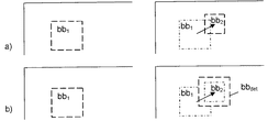
図8は、境界ボックス速度の制限を例示的かつ簡単化された方法により示す。図示されたスケールは現実的なものでなく、簡単化のために利用されていることに留意されたい。上述されるように、前のイメージimn−1では、最も顕著なエリアsa1の周辺の第1境界ボックスbb1が決定され、現在のイメージimnでは、最も顕著なエリアsa2の周辺の第2境界ボックスbb2が決定される。その後、第1境界ボックスと第2境界ボックスとの間のシフトベクトル又はシフト距離ddetが決定され、最大許容シフトベクトル又はシフト距離dmaxと比較される。 FIG. 8 illustrates bounding box speed limitations in an exemplary and simplified manner. Note that the scale shown is not realistic and is used for simplicity. As discussed above, prior to the image im n-1, is determined first bounding box bb 1 near the most prominent areas sa 1, the current image im n, of the most prominent areas sa 2 neighborhood A second bounding box bb 2 is determined. Thereafter, the shift vector or shift distance d det between the first bounding box and the second bounding box is determined and compared with the maximum allowable shift vector or shift distance d max .
あるいは、イメージimn−1とimnとの間の時間距離を考慮するとき(フレームレートfを利用して)、決定された実際の境界ボックス速度が、vdet=ddet*fに従って計算可能である。決定された実際の境界ボックス速度は、最大許容境界ボックス速度vmaxと比較される。 Alternatively, when considering the time distance between images im n−1 and im n (using the frame rate f), the determined actual bounding box velocity can be calculated according to v det = d det * f It is. The determined actual bounding box speed is compared with the maximum allowable bounding box speed vmax .
決定された境界ボックスシフトベクトルddetが最大許容境界ボックスシフトベクトルdmaxを上回る(すなわち、より長い)場合、又は決定された境界ボックス速度vdetが最大許容境界ボックス速度vmaxを上回る場合、新たな境界ボックスの位置及び/又はサイズが決定され、決定された新たな境界ボックス位置に従うサブエリアが、表示のため現在のイメージにおいてクロップ処理される(すなわち、境界ボックスにより特定されるイメージの当該部分のみが表示される)。そうでない場合、決定された境界ボックスシフトベクトルddetが最大許容境界ボックスシフトベクトルdmaxを上回らない場合、又は決定された境界ボックス速度vdetが最大許容境界ボックス速度vmaxを上回らない場合、第2境界ボックスはそのまま利用可能である。同様に、ズームファクタが説明可能である。図9は、境界ボックスズームファクタの制限を例示的かつ簡単化された方法により示す。図示されたスケールは現実的でないかもしれないことに留意されたい。上述されるように、前のイメージimn−1では、最も顕著なエリアの周辺の第1境界ボックスbb1が決定され、現在のイメージimnでは、最も顕著なエリアの周辺の第2境界ボックスbb2が決定される。本例では、第2境界ボックスbb2は、第1境界ボックスbb1よりかなり小さい。その後、ズームファクタが計算される。原理的には、ズームファクタは、例えば、z=nbb2/nbb1などに従って境界ボックスによりピクセル数から計算されてもよい。計算されたズームファクタは、最大許容ズームファクタzmaxと比較される。 If the determined bounding box shift vector d det exceeds (ie, is longer than) the maximum allowable bounding box shift vector d max , or if the determined bounding box speed v det exceeds the maximum allowable bounding box speed v max The position and / or size of the new bounding box is determined, and the sub-area according to the determined new bounding box position is cropped in the current image for display (ie, that portion of the image identified by the bounding box Only). Otherwise, if the determined bounding box shift vector d det does not exceed the maximum allowable bounding box shift vector d max , or if the determined bounding box speed v det does not exceed the maximum allowable bounding box speed v max , The two bounding box can be used as it is. Similarly, the zoom factor can be explained. FIG. 9 illustrates bounding box zoom factor limitations in an exemplary and simplified manner. Note that the scale shown may not be realistic. As described above, in the previous image im n−1 the first bounding box bb 1 around the most prominent area is determined, and in the current image im n the second bounding box around the most prominent area. bb 2 is determined. In this example, the second bounding box bb 2 is much smaller than the first bounding box bb 1 . Thereafter, the zoom factor is calculated. In principle, the zoom factor may be calculated from the number of pixels by a bounding box according to, for example, z = n bb2 / n bb1 . The calculated zoom factor is compared with the maximum allowable zoom factor z max .
決定されたズームファクタzdetが最大許容ズームファクタzmaxを上回らない場合、第2境界ボックスはそのまま利用可能である。他方、決定されたズームファクタzdetが最大許容ズームファクタzmaxを上回る場合、新たな境界ボックスbbdetのサイズは、最大許容ズームファクタzmaxが充足されるように決定される。新たな境界ボックスbbdetは、第2境界ボックスbb2と同心円状にある。決定された新たな境界ボックスbbdetの位置によるサブエリアは、表示のため現在イメージにおいてクロップ処理される。 If the determined zoom factor z det does not exceed the maximum allowable zoom factor z max , the second bounding box is still available. On the other hand, if the determined zoom factor z det exceeds the maximum allowable zoom factor z max , the size of the new bounding box bb det is determined such that the maximum allowable zoom factor z max is satisfied. The new bounding box bb det is concentric with the second bounding box bb 2 . The sub-area according to the determined position of the new bounding box bb det is cropped in the current image for display.
図8及び9に関して上記は境界ボックスのコンセプトの原理の説明であることに留意すべきである。実際の実現形態では、例えば、境界ボックス速度について、フィルタ(Kalmanフィルタなど)が境界ボックスの座標に適用され、境界ボックスの座標の軌跡及び境界ボックスのサイズをスムース化するため、境界ボックス速度は、フィルタに投入されるノイズファクタである。 It should be noted that the above with respect to FIGS. 8 and 9 is an explanation of the principle of the bounding box concept. In an actual implementation, for example, for a bounding box velocity, a filter (such as a Kalman filter) is applied to the bounding box coordinates to smooth the bounding box coordinate trajectory and the bounding box size, so that the bounding box speed is This is the noise factor input to the filter.
境界ボックス(又はクロップ処理ウィンドウ)は、一実施例では、ウィンドウに含まれるべき最も顕著なものとして選択されるピクセルのサブエリア又はサブセットを表す。一実施例では、当該ウィンドウは、目標とされる所定のアスペクト比(ユーザなどにより規定される)に設定される。このとき、一実施例では、リフレーミングアプリケーションにおいて、ウィンドウの位置(x及びy軸)及び/又はサイズは変化する。速度はボックスの位置のみを参照し、すなわち、境界ボックスが経時的にその位置を変更する方法を参照する。従って、それは、カメラの動きなどによって影響を受ける。実際には、境界ボックス速度は、フレームの可視的部分が移動する速度としてみなすことができる。 The bounding box (or cropping window) represents, in one embodiment, a sub-area or subset of pixels that are selected as the most prominent to be included in the window. In one embodiment, the window is set to a target predetermined aspect ratio (defined by the user, etc.). At this time, in one embodiment, the position (x and y axes) and / or size of the window changes in the reframing application. Velocity refers only to the position of the box, ie, how the bounding box changes its position over time. Therefore, it is affected by camera movement and the like. In practice, the bounding box speed can be viewed as the speed at which the visible portion of the frame moves.
図10は、本発明による入力ビデオシーケンスseqinのイメージを処理する装置100の原理的なブロック図を示す。本装置は、イメージ解析モジュール102とイメージ処理モジュール110とを有する。イメージ解析モジュールは、ビデオシーケンスのパラメータを決定する第1パラメータ決定モジュール103と、ビデオシーケンスの前に復号化されたGOPのパラメータを決定する第2パラメータ決定モジュール104と、ユーザ設定を決定するユーザインタフェースモジュール105とを有する。さらに、本装置は、決定されたパラメータに従ってクロップ処理される部分を決定するクロップウィンドウポジショニングモジュール106と、表示のため決定された部分をクロップ処理するクロップ処理モジュール107とを有する。クロップ処理されたイメージシーケンスseqcrは、出力に提供される。ビデオシーケンスの各種パラメータが、上述されるように、決定され、別々に又は組み合わせて利用可能である。上述したモジュールは、ハードウェアモジュール、ソフトウェアによりサポートされたハードウェアモジュール又はソフトウェアモジュールとして実現可能である。
FIG. 10 shows a basic block diagram of an
一実施例では、本装置はさらに、シーン変更検出モジュールを有する。サブシーケンスがシーン(すなわち、“ショット”)である場合、当該シーン(又はシーン変更)はシーン変更検出モジュールにより検出される。 In one embodiment, the apparatus further comprises a scene change detection module. If the subsequence is a scene (ie, “shot”), the scene (or scene change) is detected by the scene change detection module.
一実施例では、本装置はさらに、前のイメージ(imn−1)において当該前のイメージの最も顕著な部分であるピクセルのサブエリア又はサブセット(sa1)を決定する手段、前のイメージのピクセルのサブエリア又はサブセットの周辺の第1境界ボックス(bb1)を決定する手段、現在イメージにおいて当該現在イメージの最も顕著な部分であるピクセルのサブエリア又はサブセット(sa2)を決定する手段、第1境界ボックス(bb1)及び第2境界ボックス(bb2)から境界ボックスシフト(ddet)を計算する手段、第1境界ボックス(bb1)及び第2境界ボックス(bb2)の位置から境界ボックスシフト(ddet)を計算するか、又は第1境界ボックス(bb1)及び第2境界ボックス(bb2)の位置並びにビデオフレームレートから境界ボックス速度を計算する手段、決定された境界ボックスシフト(ddet)又は境界ボックス速度と連続するイメージの間の最大許容境界ボックスシフト又は境界ボックス速度とを比較する手段、及び新たな境界ボックスの位置及び/又はサイズ(bbdet)を決定し、決定した境界ボックスシフトが最大許容境界ボックスシフトを上回る場合、又は決定した境界ボックス速度が最大許容境界ボックス速度を上回る場合、現在イメージにおいて表示のため決定された新たな境界ボックスに従ってサブエリアをクロップ処理し、他方、決定した境界ボックスシフト(ddet)又は境界ボックス速度が最大許容境界ボックスシフト又は境界ボックス速度以下である場合、現在イメージにおいて表示のため決定された第2境界ボックス(bb2)に従ってサブエリアをクロップ処理する手段を有する。 In one embodiment, the apparatus further comprises means for determining a sub-area or subset (sa 1 ) of pixels in the previous image (im n−1 ) that is the most prominent part of the previous image, Means for determining a first bounding box (bb 1 ) around a sub-area or subset of pixels; means for determining a sub-area or subset (sa 2 ) of pixels that are the most prominent part of the current image in the current image; first bounding box (bb 1) and a second bounding box (bb 2) from the means for calculating a bounding box shift (d det), the position of the first bounding box (bb 1) and a second bounding box (bb 2) or calculating the bounding box shift (d det), or the first bounding box (bb 1) and a second bounding box (bb Position and means for calculating a bounding box rate from the video frame rate), and compares the maximum allowed bounding box shift or bounding box velocity between the determined bounding box shift (d det) or successive images bounding box speed Determine the means and position and / or size (bb det ) of the new bounding box and if the determined bounding box shift exceeds the maximum allowable bounding box shift, or the determined bounding box speed exceeds the maximum allowable bounding box speed If the sub-area is cropped according to the new bounding box determined for display in the current image, while the determined bounding box shift (d det ) or bounding box speed is less than or equal to the maximum allowable bounding box shift or bounding box speed If there is, Having means for the sub-area cropping process in accordance with the second bounding box is determined for display Te (bb 2).
本発明の効果は、それがコンテンツの信頼できて有用な復号化情報に基づき、リフレーミングパラメータの自動調整を実行することである。すなわち、リフレーミングパラメータは、ビデオを復号化する際に利用可能な情報を利用することによって(特に、前に復号化されたシーケンスの性質)、コンテンツに基づき自動調整される。従来、符号化中には付加的情報は挿入される必要がなかったため、符号化ビデオシーケンスが利用可能である。リフレーミングアプリケーションの設定Sは、復号化処理又は復号化ストリームから自動的に調整可能である。これらのパラメータは、上述されたように、バッファサイズs1、時間サブサンプリングファクタs2、ズームファクタs3=(zmin,zmax)及び境界ボックス速度s4の1以上である。 An advantage of the present invention is that it performs automatic adjustment of reframing parameters based on reliable and useful decryption information of the content. That is, the reframing parameters are automatically adjusted based on the content by using information available when decoding the video (particularly the nature of the previously decoded sequence). Conventionally, since no additional information had to be inserted during encoding, an encoded video sequence can be used. The reframing application setting S can be automatically adjusted from the decoding process or the decoded stream. These parameters are one or more of the buffer size s 1 , the temporal subsampling factor s 2 , the zoom factor s 3 = (z min , z max ), and the bounding box velocity s 4 as described above.
一実施例では、復号化ビデオシーケンスの設定又は入力パラメータが、それの直前の復号化シーケンスの性質に従って自動調整される。 In one embodiment, the settings or input parameters of the decoded video sequence are automatically adjusted according to the nature of the decoding sequence immediately preceding it.
本発明の一実施例では、リフレーミングアプリケーションはビデオ復号化後に実行される。 In one embodiment of the invention, the reframing application is executed after video decoding.
本発明は、表示のためのビデオを前処理する装置又はビデオを表示可能な装置において実現可能である。本発明は、特に小さなスクリーンサイズを備えたビデオ表示装置に有用である。 The present invention can be implemented in a device that preprocesses video for display or a device that can display video. The present invention is particularly useful for video display devices with a small screen size.
本発明が純粋に具体例により説明され、本発明の範囲から逸脱することなく詳細の変更が可能であることが理解されるであろう。本発明の基本的な新規な特徴がそれの好適な実施例に適用されるように図示、説明及び指摘されたが、説明された装置及び方法、開示された装置の形式及び詳細、及びそれらの動作の各種省略、置換及び変更が、本発明の趣旨から逸脱することなく当業者により可能であることが理解されるであろう。同一の結果を達成するため実質的に同じ方法により実質的に同一の機能を実行する要素のすべての組み合わせが本発明の範囲内であることが明示的に意図される。説明された実施例の間の要素の置換はまた、完全に意図及び想定される。 It will be understood that the present invention has been described purely by way of example, and modifications of detail can be made without departing from the scope of the invention. While the basic novel features of the present invention have been illustrated, described, and pointed out as applied to preferred embodiments thereof, the described apparatus and method, the types and details of the disclosed apparatus, and their It will be understood that various omissions, substitutions and changes in operation are possible by those skilled in the art without departing from the spirit of the invention. It is expressly intended that all combinations of elements performing substantially the same function in substantially the same way to achieve the same result are within the scope of the invention. Replacement of elements between the described embodiments is also fully contemplated and envisioned.
本説明、(適切である場合)請求項及び図面に開示された各特徴は、独立して又は何れか適切な組み合わせにより提供されてもよい。各特徴は、適切である場合、ハードウェア、ソフトウェア又はこれら2つの組み合わせにより実現されてもよい。請求項に現れる参照番号は、単なる具体例であり、請求項の範囲に対して限定的な効果を有さない。
以下、本願により教示される手段を例示的に列挙する。
(付記1)
ビデオシーケンスのイメージを処理する方法であって、
前記ビデオシーケンスのパラメータ、前記ビデオシーケンスの前に復号化されたサブシーケンスのパラメータ及びユーザ設定を決定するステップと、
前記決定されたパラメータに従ってクロップ処理される部分を決定するステップであって、前記クロップ処理される部分は、可変的な位置及び可変的なサイズの少なくとも1つを有する境界ボックスにより規定され、前記可変的な位置は、前記ビデオシーケンスにおける隣接フレームのイントラ符号化マクロブロックの間の相関に依存し、前記相関の第1相関値について、前記境界ボックス位置は、前記第1相関値より高い又は低い相関値に対してより速く変化し、前記可変的なサイズは、現在のGOP又はシーンの第1フレームのマクロブロックコストマップのパラメータから計算される最大ズームファクタに依存し、ゼロに等しいコストを有するマクロブロックのパーセンテージがより低い場合、より大きな最大ズームファクタが許容される、前記決定するステップと、
リフレーミングステップにおいて、表示のため前記決定された部分をクロップ処理するステップと、
を有する方法。
(付記2)
前記サブシーケンスはGOP又はシーンであり、前記シーンはシーン変更検出により検出される、付記1記載の方法。
(付記3)
前記ビデオシーケンスのパラメータ又は前に復号化されたサブシーケンスのパラメータは、GOPサイズ、シーン長、時間サブサンプリングファクタ、最大及び最小ズームファクタ並びに境界ボックス速度の少なくとも1つを有する、付記1又は2記載の方法。
(付記4)
前記ビデオシーケンスのパラメータを決定するステップは、現在のイメージについて、
前のイメージにおいて、前記前のイメージの最も顕著な部分であるピクセルのサブエリア又はサブセットを決定するステップと、
前記前のイメージのピクセルのサブエリア又はサブセットの周辺の第1境界ボックスを決定するステップと、
前記現在のイメージにおいて、前記現在のイメージの最も顕著な部分であるピクセルのサブエリア又はサブセットを決定するステップと、
前記現在のイメージの前記エリアの周辺の第2境界ボックスを決定するステップであって、前記第2境界ボックスは前記可変的な境界ボックス位置を有する、前記第2境界ボックスを決定するステップと、
前記第1境界ボックスと前記第2境界ボックスとの位置から境界ボックスシフトを計算するか、又は前記第1境界ボックスと前記第2境界ボックスとの位置及び前記ビデオフレームレートから、境界ボックスシフトと境界ボックス速度とを計算するステップと、
前記決定された境界ボックスシフト又は境界ボックス速度と、連続するイメージの間の最大許容境界ボックスシフト又は境界ボックス速度とを比較するステップと、
前記決定された境界ボックスシフトが前記最大許容境界ボックスシフトを上回る場合、又は前記決定された境界ボックス速度が前記最大許容境界ボックス速度を上回る場合、新たな境界ボックスの位置及び/又はサイズを決定し、前記現在のイメージにおいて表示のため前記決定された新たな境界ボックスに従って前記サブエリアをクロップ処理するステップと、
他方、前記決定された境界ボックスシフト又は境界ボックス速度が前記最大許容境界ボックスシフト又は最大許容境界ボックス速度以下である場合、前記現在のイメージにおいて表示のため前記決定された第2境界ボックスに従って前記サブエリアをクロップ処理するステップと、
を有する、付記1乃至3何れか一項記載の方法。
(付記5)
前記最大許容境界ボックスシフト又は境界ボックス速度は、前記ビデオシーケンスの前に復号化されたサブシーケンスのパラメータから決定される、付記1乃至4何れか一項記載の方法。
(付記6)
前記最大許容境界ボックス速度は、
に従って計算され、IntraMapはPピクチャ又はBピクチャにおけるイントラ符号化されたMBのマップであり、CCは現在のIntraMapと隣接するIntraMapとの間の相関係数であり、V max は前記境界ボックスの最大速度であり、m及びσは前記境界ボックス速度の分布の平均及び標準偏差である、付記1乃至5何れか一項記載の方法。
(付記7)
前記クロップ処理ウィンドウパラメータを経時的にスムース化するステップをさらに有し、
前記クロップ処理ウィンドウパラメータを経時的にスムース化するため、前記リフレーミングステップにおいてバッファが利用され、
前記バッファのサイズは、前記GOPサイズに従って調整される、付記1乃至6何れか一項記載の方法。
(付記8)
時間サブサンプリングファクタ又は時間サブサンプリングスキームが、時間サブサンプリングモードに従って設定され、
第1サブサンプリングモードでは、前記リフレーミングステップがすべてのフレームに適用され、
第2サブサンプリングモードでは、前記リフレーミングステップがすべてのIフレーム及びPフレームに適用され、0以上のBフレームには適用されず、
第3サブサンプリングモードでは、前記リフレーミングステップがすべてのIフレームに適用され、何れのBフレームに適用されず、0以上のPフレームに適用されない、付記1乃至7何れか一項記載の方法。
(付記9)
前記サブサンプリングモードの1つは、ビットレート要求とイメージ品質要求との少なくとも1つに従って選択される、付記8記載の方法。
(付記10)
前記クロップ処理される部分は、クロップ処理ウィンドウにより規定され、
最大又は最小許容ズームファクタ又はズームファクタのペアを決定するステップをさらに有し、
前記最大又は最小許容ズームファクタは、前記クロップ処理ウィンドウが経時的に変化する境界を規定し、又は前記ズームファクタのペアは、前記クロップ処理ウィンドウが経時的に変化する2つの境界を規定する、付記1乃至9何れか一項記載の方法。
(付記11)
前記ズームファクタのペアは、現在のGOP又はシーンの第1フレームのマクロブロックコストマップのパラメータから計算される、付記10記載の方法。
(付記12)
最小許容ズームファクタは、
により計算され、
最大許容ズームファクタは、
により計算され、nb MB は前記イメージ内のMBの総数であり、nb MBcost0 は0に等しいコストを有するMBの個数であり、nb MBadj は最大のコストを有する隣接MBの個数である、付記1乃至11何れか一項記載の方法。
(付記13)
ビデオシーケンスのイメージを処理する装置であって、
前記ビデオシーケンスのパラメータを決定し、前記ビデオシーケンスの前に復号化されたサブシーケンスのパラメータを決定し、ユーザ設定を決定するイメージ解析手段と、
前記決定されたパラメータに従ってクロップ処理される部分を決定し、表示のため前記決定された部分をクロップ処理するイメージ処理手段であって、前記クロップ処理される部分は、可変的な位置及び可変的なサイズの少なくとも1つを有する境界ボックスにより規定され、前記可変的な位置は、前記ビデオシーケンスにおける隣接フレームのイントラ符号化マクロブロックの間の相関に依存し、前記相関の第1相関値について、前記境界ボックス位置は、前記第1相関値より高い又は低い相関値についてより速く変化し、前記可変的サイズは、現在のGOP又はシーンの第1フレームのマクロブロックコストマップのパラメータから計算されるズームファクタに依存し、ゼロに等しいコストを有するマクロブロックのパーセンテージがより低い場合、より高い最大ズームファクタが許容される、前記イメージ解析手段と、
を有する装置。
(付記14)
シーン変更検出モジュールをさらに有し、
前記サブシーケンスは、GOP又はシーンであり、
前記シーンは、前記シーン検出モジュールにより検出される、付記13記載の装置。
(付記15)
前のイメージにおいて、前記前のイメージの最も顕著な部分であるピクセルのサブエリア又はサブセットを決定する手段と、
前記前のイメージのピクセルのサブエリア又はサブセットの周辺の第1境界ボックスを決定する手段と、
前記現在のイメージにおいて、前記現在のイメージの最も顕著な部分であるピクセルのサブエリア又はサブセットを決定する手段と、
前記現在のイメージの前記エリアの周辺の第2境界ボックスを決定する手段と、
前記第1境界ボックスと前記第2境界ボックスとの位置から境界ボックスシフトを計算するか、又は前記第1境界ボックスと前記第2境界ボックスとの位置及び前記ビデオフレームレートから、境界ボックス速度とを計算する手段と、
前記決定された境界ボックスシフト又は境界ボックス速度と、連続するイメージの間の最大許容境界ボックスシフト又は境界ボックス速度とを比較する手段と、
前記決定された境界ボックスシフトが前記最大許容境界ボックスシフトを上回る場合、又は前記決定された境界ボックス速度が前記最大許容境界ボックス速度を上回る場合、新たな境界ボックスの位置及び/又はサイズを決定し、前記現在のイメージにおいて表示のため前記決定された新たな境界ボックスに従って前記サブエリアをクロップ処理し、前記決定された境界ボックスシフト又は境界ボックス速度が前記最大許容境界ボックスシフト又は最大許容境界ボックス速度以下である場合、前記現在のイメージにおいて表示のため前記決定された第2境界ボックスに従って前記サブエリアをクロップ処理する手段と、
を有する、付記13又は14記載の装置。
Each feature disclosed in the description, (where appropriate) the claims and drawings may be provided independently or in any appropriate combination. Each feature may be implemented by hardware, software, or a combination of the two, where appropriate. Reference numerals appearing in the claims are by way of illustration only and shall have no limiting effect on the scope of the claims.
Hereinafter, the means taught by the present application will be exemplified.
(Appendix 1)
A method for processing an image of a video sequence, comprising:
Determining parameters of the video sequence, parameters of sub-sequences decoded before the video sequence and user settings;
Determining a portion to be cropped according to the determined parameter, wherein the portion to be cropped is defined by a bounding box having at least one of a variable position and a variable size; The general position depends on the correlation between intra-coded macroblocks of adjacent frames in the video sequence, and for the first correlation value of the correlation, the bounding box position is higher or lower than the first correlation value. Macros that change more quickly with respect to the value and the variable size depends on the maximum zoom factor calculated from the parameters of the macroblock cost map of the first frame of the current GOP or scene and has a cost equal to zero If the block percentage is lower, a larger maximum zoom factor is acceptable. That the steps of the decision,
Cropping the determined portion for display in a reframing step;
Having a method.
(Appendix 2)
The method according to
(Appendix 3)
(Appendix 4)
Determining the parameters of the video sequence for the current image:
Determining, in the previous image, a sub-area or subset of pixels that is the most prominent portion of the previous image;
Determining a first bounding box around a sub-area or subset of pixels of the previous image;
Determining in the current image a sub-area or subset of pixels that is the most prominent part of the current image;
Determining a second bounding box around the area of the current image, wherein the second bounding box has the variable bounding box position;
Calculate a bounding box shift from the position of the first bounding box and the second bounding box, or the bounding box shift and bound from the position of the first bounding box and the second bounding box and the video frame rate Calculating the box speed;
Comparing the determined bounding box shift or bounding box speed with a maximum allowable bounding box shift or bounding box speed between successive images;
If the determined bounding box shift exceeds the maximum permissible bounding box shift, or if the determined bounding box speed exceeds the maximum permissible bounding box speed, a new bounding box position and / or size is determined. Cropping the sub-area according to the determined new bounding box for display in the current image;
On the other hand, if the determined bounding box shift or bounding box speed is less than or equal to the maximum permissible bounding box shift or the maximum permissible bounding box speed, the sub-boundary according to the determined second bounding box for display in the current image. Cropping the area;
The method according to any one of
(Appendix 5)
The method according to one of
(Appendix 6)
The maximum allowable bounding box speed is
IntraMap is a map of intra-coded MBs in a P or B picture, CC is the correlation coefficient between the current IntraMap and the adjacent IntraMap, and V max is the maximum of the bounding box 6. The method according to any one of
(Appendix 7)
Smoothing the cropping window parameter over time;
A buffer is used in the reframing step to smooth the crop window parameter over time,
The method according to any one of
(Appendix 8)
The time subsampling factor or time subsampling scheme is set according to the time subsampling mode;
In the first sub-sampling mode, the reframing step is applied to all frames;
In the second sub-sampling mode, the reframing step is applied to all I frames and P frames, not 0 or more B frames,
The method according to any one of
(Appendix 9)
The method of claim 8, wherein one of the sub-sampling modes is selected according to at least one of a bit rate requirement and an image quality requirement.
(Appendix 10)
The portion to be cropped is defined by a crop processing window,
Determining the maximum or minimum allowable zoom factor or zoom factor pair;
The maximum or minimum allowable zoom factor defines a boundary where the cropping window changes over time, or the zoom factor pair defines two boundaries where the cropping window changes over time The method according to any one of 1 to 9.
(Appendix 11)
The method of
(Appendix 12)
The minimum allowable zoom factor is
Calculated by
The maximum allowable zoom factor is
Where nb MB is the total number of MBs in the image, nb MBcost0 is the number of MBs with a cost equal to 0, and nb MBadj is the number of neighboring MBs with the highest cost, 11. The method according to any one of 11 above.
(Appendix 13)
An apparatus for processing an image of a video sequence,
Image analysis means for determining parameters of the video sequence, determining parameters of sub-sequences decoded before the video sequence, and determining user settings;
Image processing means for determining a portion to be cropped according to the determined parameter and cropping the determined portion for display, wherein the cropped portion has a variable position and a variable Defined by a bounding box having at least one of the sizes, the variable position depends on a correlation between intra-coded macroblocks of adjacent frames in the video sequence, and for a first correlation value of the correlation, The bounding box position changes faster for correlation values higher or lower than the first correlation value, and the variable size is a zoom factor calculated from the parameters of the macroblock cost map of the first frame of the current GOP or scene. The percentage of macroblocks with a cost equal to zero Lower case, a higher maximum zoom factor is allowed, said image analysis means,
Having a device.
(Appendix 14)
A scene change detection module;
The subsequence is a GOP or a scene,
The apparatus of
(Appendix 15)
Means for determining in a previous image a sub-area or subset of pixels that is the most prominent portion of said previous image;
Means for determining a first bounding box around a sub-area or subset of pixels of the previous image;
Means for determining, in the current image, a sub-area or subset of pixels that is the most prominent part of the current image;
Means for determining a second bounding box around the area of the current image;
Calculate a bounding box shift from the position of the first bounding box and the second bounding box, or the bounding box speed from the position of the first bounding box and the second bounding box and the video frame rate. Means for calculating;
Means for comparing said determined bounding box shift or bounding box speed with a maximum allowable bounding box shift or bounding box speed between successive images;
If the determined bounding box shift exceeds the maximum permissible bounding box shift, or if the determined bounding box speed exceeds the maximum permissible bounding box speed, a new bounding box position and / or size is determined. Cropping the sub-area according to the determined new bounding box for display in the current image, wherein the determined bounding box shift or bounding box speed is the maximum permissible bounding box shift or the maximum permissible bounding box speed Means for cropping the sub-area according to the determined second bounding box for display in the current image if
15. The apparatus according to
11 符号化入力ビデオシーケンス
12 復号化ビデオシーケンス
13 デコーダ設定
14 リフレーミング設定
11 Encoded
Claims (15)
前記ビデオシーケンスのパラメータ、前記ビデオシーケンスの前に復号化されたサブシーケンスのパラメータ及びユーザ設定を決定するステップと、
前記決定されたパラメータに従ってクロップ処理される部分を決定するステップであって、前記クロップ処理される部分は、可変的な位置及び可変的なサイズの少なくとも1つを有する境界ボックスにより規定され、前記可変的な位置は、前記ビデオシーケンスにおける隣接フレームのイントラ符号化マクロブロックの間の相関に依存し、前記相関の第1相関値について、境界ボックス位置は、前記第1相関値より高い又は低い相関値に対してより速く変化し、前記可変的なサイズは、現在のGOP又はシーンの第1フレームのマクロブロックコストマップのパラメータから計算される最大ズームファクタに依存し、ゼロに等しいコストを有するマクロブロックのパーセンテージがより低い場合、より大きな最大ズームファクタが許容される、前記決定するステップと、
リフレーミングステップにおいて、表示のため前記決定された部分をクロップ処理するステップと、
を有する方法。 A method for processing an image of a video sequence, comprising:
Determining parameters of the video sequence, parameters of sub-sequences decoded before the video sequence and user settings;
Determining a portion to be cropped according to the determined parameter, wherein the portion to be cropped is defined by a bounding box having at least one of a variable position and a variable size; The general position depends on the correlation between intra-coded macroblocks of adjacent frames in the video sequence, and for the first correlation value of the correlation, the bounding box position is higher or lower than the first correlation value. The variable size depends on the maximum zoom factor calculated from the parameters of the macroblock cost map of the first frame of the current GOP or scene and has a cost equal to zero If the percentage of is lower, a larger maximum zoom factor is allowed And said determining step,
Cropping the determined portion for display in a reframing step;
Having a method.
前のイメージにおいて、前記前のイメージの最も顕著な部分であるピクセルのサブエリア又はサブセットを決定するステップと、
前記前のイメージのピクセルのサブエリア又はサブセットの周辺の第1境界ボックスを決定するステップと、
前記現在のイメージにおいて、前記現在のイメージの最も顕著な部分であるピクセルのサブエリア又はサブセットを決定するステップと、
前記現在のイメージの前記エリアの周辺の第2境界ボックスを決定するステップであって、前記第2境界ボックスは前記可変的な境界ボックス位置を有する、前記第2境界ボックスを決定するステップと、
前記第1境界ボックスと前記第2境界ボックスとの位置から境界ボックスシフトを計算するか、又は前記第1境界ボックスと前記第2境界ボックスとの位置及びビデオフレームレートから、境界ボックスシフトと境界ボックス速度とを計算するステップと、
前記決定された境界ボックスシフト又は境界ボックス速度と、連続するイメージの間の最大許容境界ボックスシフト又は最大許容境界ボックス速度とを比較するステップと、
前記決定された境界ボックスシフトが前記最大許容境界ボックスシフトを上回る場合、又は前記決定された境界ボックス速度が前記最大許容境界ボックス速度を上回る場合、新たな境界ボックスの位置及び/又はサイズを決定し、前記現在のイメージにおいて表示のため前記決定された新たな境界ボックスに従って前記サブエリアをクロップ処理するステップと、
他方、前記決定された境界ボックスシフト又は境界ボックス速度が前記最大許容境界ボックスシフト又は最大許容境界ボックス速度以下である場合、前記現在のイメージにおいて表示のため前記決定された第2境界ボックスに従って前記サブエリアをクロップ処理するステップと、
を有する、請求項1乃至3何れか一項記載の方法。 Determining the parameters of the video sequence for the current image:
Determining, in the previous image, a sub-area or subset of pixels that is the most prominent portion of the previous image;
Determining a first bounding box around a sub-area or subset of pixels of the previous image;
Determining in the current image a sub-area or subset of pixels that is the most prominent part of the current image;
Determining a second bounding box around the area of the current image, wherein the second bounding box has the variable bounding box position;
From the position及Bibi Deo frame rate of the first bounding box whether to calculate the bounding box shift from the position of the second bounding box, or the second bounding box and the first bounding box, and the bounding box shift Calculating a bounding box velocity;
Comparing the determined bounding box shift or bounding box speed to a maximum allowable bounding box shift or maximum allowable bounding box speed between successive images;
If the determined bounding box shift exceeds the maximum permissible bounding box shift, or if the determined bounding box speed exceeds the maximum permissible bounding box speed, a new bounding box position and / or size is determined. Cropping the sub-area according to the determined new bounding box for display in the current image;
On the other hand, if the determined bounding box shift or bounding box speed is less than or equal to the maximum permissible bounding box shift or the maximum permissible bounding box speed, the sub-boundary according to the determined second bounding box for display in the current image. Cropping the area;
The method according to claim 1, comprising:
に従って計算され、IntraMapはPピクチャ又はBピクチャにおけるイントラ符号化されたMBのマップであり、CCは現在のIntraMapと隣接するIntraMapとの間の相関係数であり、Vmaxは前記境界ボックスの最大速度であり、m及びσは前記境界ボックス速度の分布の平均及び標準偏差である、請求項3乃至5何れか一項記載の方法。 The maximum allowable bounding box speed is
IntraMap is a map of intra-coded MBs in a P or B picture, CC is the correlation coefficient between the current IntraMap and the adjacent IntraMap, and V max is the maximum of the bounding box 6. A method according to any one of claims 3 to 5, wherein m is the velocity and m and σ are the mean and standard deviation of the distribution of the bounding box velocity.
前記クロップ処理ウィンドウパラメータを経時的にスムース化するため、前記リフレーミングステップにおいてバッファが利用され、
前記バッファのサイズは、前記GOPサイズに従って調整される、請求項3に記載の方法。 Further comprising the step of temporally smooth the cropping process window parameters,
A buffer is used in the reframing step to smooth the crop window parameter over time,
The method of claim 3 , wherein the size of the buffer is adjusted according to the GOP size.
第1サブサンプリングモードでは、前記リフレーミングステップがすべてのフレームに適用され、
第2サブサンプリングモードでは、前記リフレーミングステップがすべてのIフレーム及びPフレームに適用され、0以上のBフレームには適用されず、
第3サブサンプリングモードでは、前記リフレーミングステップがすべてのIフレームに適用され、何れのBフレームにも適用されず、0以上のPフレームに適用されない、請求項1乃至7何れか一項記載の方法。 The time subsampling factor or time subsampling scheme is set according to the time subsampling mode;
In the first sub-sampling mode, the reframing step is applied to all frames;
In the second sub-sampling mode, the reframing step is applied to all I frames and P frames, not 0 or more B frames,
In the third sub-sampling mode, the reframing step is applied to all I-frame is not applied to any of the B-frame, it does not apply to zero or more P frames, of claims 1 to 7 any one claim Method.
最大又は最小許容ズームファクタ又はズームファクタのペアを決定するステップをさらに有し、
前記最大又は最小許容ズームファクタは、前記クロップ処理ウィンドウが経時的に変化する境界を規定し、又は前記ズームファクタのペアは、前記クロップ処理ウィンドウが経時的に変化する2つの境界を規定する、請求項1乃至9何れか一項記載の方法。 The portion to be cropped is defined by a crop processing window,
Determining the maximum or minimum allowable zoom factor or zoom factor pair;
The maximum or minimum allowable zoom factor defines a boundary where the cropping window changes over time, or the zoom factor pair defines two boundaries where the cropping window changes over time. Item 10. The method according to any one of Items 1 to 9.
により計算され、
最大許容ズームファクタは、
により計算され、nbMBは前記イメージ内のMBの総数であり、nbMBcost0は0に等しいコストを有するMBの個数であり、nbMBadjは最大のコストを有する隣接MBの個数である、請求項1乃至11何れか一項記載の方法。 The minimum allowable zoom factor is
Calculated by
The maximum allowable zoom factor is
The nb MB is the total number of MBs in the image, nb MBcost0 is the number of MBs with a cost equal to 0, and nb MBadj is the number of neighboring MBs with the highest cost. The method as described in any one of thru | or 11.
前記ビデオシーケンスのパラメータを決定し、前記ビデオシーケンスの前に復号化されたサブシーケンスのパラメータを決定し、ユーザ設定を決定するイメージ解析手段と、
前記決定されたパラメータに従ってクロップ処理される部分を決定し、表示のため前記決定された部分をクロップ処理するイメージ処理手段であって、前記クロップ処理される部分は、可変的な位置及び可変的なサイズの少なくとも1つを有する境界ボックスにより規定され、前記可変的な位置は、前記ビデオシーケンスにおける隣接フレームのイントラ符号化マクロブロックの間の相関に依存し、前記相関の第1相関値について、境界ボックス位置は、前記第1相関値より高い又は低い相関値についてより速く変化し、前記可変的サイズは、現在のGOP又はシーンの第1フレームのマクロブロックコストマップのパラメータから計算されるズームファクタに依存し、ゼロに等しいコストを有するマクロブロックのパーセンテージがより低い場合、より高い最大ズームファクタが許容される、前記イメージ解析手段と、
を有する装置。 An apparatus for processing an image of a video sequence,
Image analysis means for determining parameters of the video sequence, determining parameters of sub-sequences decoded before the video sequence, and determining user settings;
Image processing means for determining a portion to be cropped according to the determined parameter and cropping the determined portion for display, wherein the cropped portion has a variable position and a variable Defined by a bounding box having at least one of the sizes, wherein the variable position depends on a correlation between intra-coded macroblocks of adjacent frames in the video sequence, and for a first correlation value of the correlation, The box position changes faster for correlation values higher or lower than the first correlation value, and the variable size is a zoom factor calculated from the macroblock cost map parameters of the current GOP or scene first frame. The percentage of macroblocks that depend on and have a cost equal to zero is lower If a higher maximum zoom factor is allowed, said image analysis means,
Having a device.
前記サブシーケンスは、GOP又はシーンであり、
前記シーンは、前記シーン変更検出モジュールにより検出される、請求項13記載の装置。 A scene change detection module;
The subsequence is a GOP or a scene,
The apparatus of claim 13, wherein the scene is detected by the scene change detection module.
前記前のイメージのピクセルのサブエリア又はサブセットの周辺の第1境界ボックスを決定する手段と、
前記現在のイメージにおいて、前記現在のイメージの最も顕著な部分であるピクセルのサブエリア又はサブセットを決定する手段と、
前記現在のイメージの前記エリアの周辺の第2境界ボックスを決定する手段と、
前記第1境界ボックスと前記第2境界ボックスとの位置から境界ボックスシフトを計算するか、又は前記第1境界ボックスと前記第2境界ボックスとの位置及びビデオフレームレートから、境界ボックス速度とを計算する手段と、
前記決定された境界ボックスシフト又は境界ボックス速度と、連続するイメージの間の最大許容境界ボックスシフト又は境界ボックス速度とを比較する手段と、
前記決定された境界ボックスシフトが前記最大許容境界ボックスシフトを上回る場合、又は前記決定された境界ボックス速度が前記最大許容境界ボックス速度を上回る場合、新たな境界ボックスの位置及び/又はサイズを決定し、前記現在のイメージにおいて表示のため前記決定された新たな境界ボックスに従って前記サブエリアをクロップ処理し、前記決定された境界ボックスシフト又は境界ボックス速度が前記最大許容境界ボックスシフト又は最大許容境界ボックス速度以下である場合、前記現在のイメージにおいて表示のため前記決定された第2境界ボックスに従って前記サブエリアをクロップ処理する手段と、
を有する、請求項13又は14記載の装置。 Means for determining in a previous image a sub-area or subset of pixels that is the most prominent portion of said previous image;
Means for determining a first bounding box around a sub-area or subset of pixels of the previous image;
Means for determining, in the current image, a sub-area or subset of pixels that is the most prominent part of the current image;
Means for determining a second bounding box around the area of the current image;
From the position及Bibi Deo frame rate of the first bounding box whether to calculate the bounding box shift from the position of the second bounding box, or the second bounding box and the first bounding box, and the bounding box speed A means of calculating
Means for comparing said determined bounding box shift or bounding box speed with a maximum allowable bounding box shift or bounding box speed between successive images;
If the determined bounding box shift exceeds the maximum permissible bounding box shift, or if the determined bounding box speed exceeds the maximum permissible bounding box speed, a new bounding box position and / or size is determined. Cropping the sub-area according to the determined new bounding box for display in the current image, wherein the determined bounding box shift or bounding box speed is the maximum permissible bounding box shift or the maximum permissible bounding box speed Means for cropping the sub-area according to the determined second bounding box for display in the current image if
15. The device according to claim 13 or 14, comprising:
Applications Claiming Priority (2)
| Application Number | Priority Date | Filing Date | Title |
|---|---|---|---|
| EP12305779.6A EP2680219A1 (en) | 2012-06-29 | 2012-06-29 | Method for reframing images of a video sequence, and apparatus for reframing images of a video sequence |
| EP12305779.6 | 2012-06-29 |
Publications (3)
| Publication Number | Publication Date |
|---|---|
| JP2014011807A JP2014011807A (en) | 2014-01-20 |
| JP2014011807A5 JP2014011807A5 (en) | 2016-08-12 |
| JP6198484B2 true JP6198484B2 (en) | 2017-09-20 |
Family
ID=48655986
Family Applications (1)
| Application Number | Title | Priority Date | Filing Date |
|---|---|---|---|
| JP2013136263A Expired - Fee Related JP6198484B2 (en) | 2012-06-29 | 2013-06-28 | Method and apparatus for reframing an image of a video sequence |
Country Status (5)
| Country | Link |
|---|---|
| US (1) | US8891016B2 (en) |
| EP (2) | EP2680219A1 (en) |
| JP (1) | JP6198484B2 (en) |
| KR (1) | KR20140004022A (en) |
| CN (1) | CN103533370B (en) |
Families Citing this family (12)
| Publication number | Priority date | Publication date | Assignee | Title |
|---|---|---|---|---|
| EP2582134A1 (en) * | 2011-10-12 | 2013-04-17 | Thomson Licensing | Saliency value determination of predictively encoded video streams |
| US8994838B2 (en) * | 2013-04-16 | 2015-03-31 | Nokia Corporation | Motion adaptive cropping for video stabilization |
| US10051281B2 (en) * | 2014-05-22 | 2018-08-14 | Apple Inc. | Video coding system with efficient processing of zooming transitions in video |
| KR101952359B1 (en) | 2014-09-29 | 2019-02-26 | 엘지이노텍 주식회사 | Composite magnetic sheet and wireless charging module consisting the same |
| KR20170098232A (en) | 2014-12-22 | 2017-08-29 | 톰슨 라이센싱 | Method and apparatus for generating an extrapolated image based on object detection |
| CN104702968B (en) * | 2015-02-17 | 2019-06-11 | 华为技术有限公司 | A kind of video frame frame losing method and video transmission device |
| CN107431762B (en) * | 2015-04-14 | 2020-12-01 | 索尼公司 | Image processing apparatus, image processing method, and image processing system |
| WO2017075804A1 (en) * | 2015-11-06 | 2017-05-11 | Microsoft Technology Licensing, Llc | Flexible reference picture management for video encoding and decoding |
| CN105721851A (en) * | 2016-02-02 | 2016-06-29 | 福建天晴数码有限公司 | Video ghosting optimization method and system of parallax barrier 3D display device |
| CN110418195B (en) * | 2019-08-09 | 2020-08-18 | 华南理工大学 | Real-time video abbreviating method based on optimal cutting |
| US11195039B2 (en) * | 2020-03-10 | 2021-12-07 | International Business Machines Corporation | Non-resource-intensive object detection |
| CN112907617B (en) * | 2021-01-29 | 2024-02-20 | 深圳壹秘科技有限公司 | Video processing method and device |
Family Cites Families (12)
| Publication number | Priority date | Publication date | Assignee | Title |
|---|---|---|---|---|
| WO2001015459A1 (en) * | 1999-08-24 | 2001-03-01 | Fujitsu Limited | Time-varying image processor, its method, and recorded medium |
| US7266771B1 (en) * | 2000-04-21 | 2007-09-04 | Vulcan Patents Llc | Video stream representation and navigation using inherent data |
| US7428338B2 (en) * | 2002-01-10 | 2008-09-23 | Ricoh Co., Ltd. | Header-based processing of images compressed using multi-scale transforms |
| US7609947B2 (en) * | 2004-09-10 | 2009-10-27 | Panasonic Corporation | Method and apparatus for coordinating playback from multiple video sources |
| KR20090006068A (en) * | 2006-02-13 | 2009-01-14 | 스넬 앤드 윌콕스 리미티드 | Method and apparatus for modifying a moving image sequence |
| JP4714039B2 (en) * | 2006-02-27 | 2011-06-29 | 株式会社東芝 | Video playback apparatus and video playback method |
| EP2087739A2 (en) * | 2006-10-25 | 2009-08-12 | Thomson Licensing | Methods and apparatus for efficient first-pass encoding in a multi-pass encoder |
| FR2912237A1 (en) * | 2007-02-07 | 2008-08-08 | Thomson Licensing Sas | IMAGE PROCESSING METHOD |
| CN102047656B (en) * | 2008-06-18 | 2012-07-18 | 三菱电机株式会社 | Three-dimensional video conversion recording device, three-dimensional video conversion recording method, three-dimensional video conversion device, and three-dimensional video transmission device |
| US8237771B2 (en) * | 2009-03-26 | 2012-08-07 | Eastman Kodak Company | Automated videography based communications |
| JP2012002683A (en) * | 2010-06-17 | 2012-01-05 | Fuji Electric Co Ltd | Stereo image processing method and stereo image processing device |
| EP2549754A1 (en) * | 2011-07-19 | 2013-01-23 | Thomson Licensing | Method and apparatus for reframing and encoding an original video signal |
-
2012
- 2012-06-29 EP EP12305779.6A patent/EP2680219A1/en not_active Withdrawn
-
2013
- 2013-06-18 EP EP13172393.4A patent/EP2680220B1/en not_active Not-in-force
- 2013-06-26 US US13/928,146 patent/US8891016B2/en not_active Expired - Fee Related
- 2013-06-28 KR KR1020130075852A patent/KR20140004022A/en not_active Application Discontinuation
- 2013-06-28 JP JP2013136263A patent/JP6198484B2/en not_active Expired - Fee Related
- 2013-07-01 CN CN201310270910.7A patent/CN103533370B/en not_active Expired - Fee Related
Also Published As
| Publication number | Publication date |
|---|---|
| CN103533370A (en) | 2014-01-22 |
| US20140002742A1 (en) | 2014-01-02 |
| EP2680220B1 (en) | 2018-08-08 |
| CN103533370B (en) | 2018-05-18 |
| KR20140004022A (en) | 2014-01-10 |
| US8891016B2 (en) | 2014-11-18 |
| EP2680219A1 (en) | 2014-01-01 |
| EP2680220A2 (en) | 2014-01-01 |
| JP2014011807A (en) | 2014-01-20 |
| EP2680220A3 (en) | 2015-04-29 |
Similar Documents
| Publication | Publication Date | Title |
|---|---|---|
| JP6198484B2 (en) | Method and apparatus for reframing an image of a video sequence | |
| US10977809B2 (en) | Detecting motion dragging artifacts for dynamic adjustment of frame rate conversion settings | |
| US9905031B2 (en) | Method and related apparatus for capturing and processing image data | |
| US9118846B2 (en) | Apparatus for generating an image with defocused background and method thereof | |
| AU2011352102B2 (en) | Video coding | |
| JP5908174B2 (en) | Image processing apparatus and image processing method | |
| US8983175B2 (en) | Video processing method and device for depth extraction | |
| US10277901B2 (en) | Encoding a video stream having a privacy mask | |
| US10354394B2 (en) | Dynamic adjustment of frame rate conversion settings | |
| US20160210787A1 (en) | Method for Optimizing Occlusion in Augmented Reality Based On Depth Camera | |
| JP2014011807A5 (en) | ||
| CN107295296B (en) | Method and system for selectively storing and recovering monitoring video | |
| EP3796655B1 (en) | Video privacy mask in forward predicted video frame | |
| US10798418B2 (en) | Method and encoder for encoding a video stream in a video coding format supporting auxiliary frames | |
| KR20170133468A (en) | Temporal flattening of video enhancements | |
| US8644555B2 (en) | Device and method for detecting movement of object | |
| Kim et al. | Content-preserving video stitching method for multi-camera systems | |
| JP2006270301A (en) | Scene change detecting apparatus and scene change detection program | |
| KR102315471B1 (en) | Image processing method and device | |
| US20100021008A1 (en) | System and Method for Face Tracking | |
| JP2007512750A (en) | Detection of local image space-temporal details in video signals | |
| CN114157870A (en) | Encoding method, medium, and electronic device | |
| US20160165271A1 (en) | Method and device for determining properties of a graphical overlay for a video stream | |
| US11290735B1 (en) | Visual element encoding parameter tuning | |
| Toka et al. | A fast method of fog and haze removal |
Legal Events
| Date | Code | Title | Description |
|---|---|---|---|
| A521 | Request for written amendment filed |
Free format text: JAPANESE INTERMEDIATE CODE: A523 Effective date: 20160627 |
|
| A621 | Written request for application examination |
Free format text: JAPANESE INTERMEDIATE CODE: A621 Effective date: 20160627 |
|
| A977 | Report on retrieval |
Free format text: JAPANESE INTERMEDIATE CODE: A971007 Effective date: 20170131 |
|
| A131 | Notification of reasons for refusal |
Free format text: JAPANESE INTERMEDIATE CODE: A131 Effective date: 20170214 |
|
| A601 | Written request for extension of time |
Free format text: JAPANESE INTERMEDIATE CODE: A601 Effective date: 20170511 |
|
| A521 | Request for written amendment filed |
Free format text: JAPANESE INTERMEDIATE CODE: A523 Effective date: 20170714 |
|
| TRDD | Decision of grant or rejection written | ||
| A01 | Written decision to grant a patent or to grant a registration (utility model) |
Free format text: JAPANESE INTERMEDIATE CODE: A01 Effective date: 20170725 |
|
| A61 | First payment of annual fees (during grant procedure) |
Free format text: JAPANESE INTERMEDIATE CODE: A61 Effective date: 20170822 |
|
| R150 | Certificate of patent or registration of utility model |
Ref document number: 6198484 Country of ref document: JP Free format text: JAPANESE INTERMEDIATE CODE: R150 |
|
| LAPS | Cancellation because of no payment of annual fees |