JP6196607B2 - Image processing method, control program, and image processing apparatus - Google Patents
Image processing method, control program, and image processing apparatus Download PDFInfo
- Publication number
- JP6196607B2 JP6196607B2 JP2014265039A JP2014265039A JP6196607B2 JP 6196607 B2 JP6196607 B2 JP 6196607B2 JP 2014265039 A JP2014265039 A JP 2014265039A JP 2014265039 A JP2014265039 A JP 2014265039A JP 6196607 B2 JP6196607 B2 JP 6196607B2
- Authority
- JP
- Japan
- Prior art keywords
- image
- pixel
- contour
- pixels
- original
- Prior art date
- Legal status (The legal status is an assumption and is not a legal conclusion. Google has not performed a legal analysis and makes no representation as to the accuracy of the status listed.)
- Active
Links
Images


Classifications
-
- G—PHYSICS
- G02—OPTICS
- G02B—OPTICAL ELEMENTS, SYSTEMS OR APPARATUS
- G02B7/00—Mountings, adjusting means, or light-tight connections, for optical elements
- G02B7/28—Systems for automatic generation of focusing signals
-
- H—ELECTRICITY
- H04—ELECTRIC COMMUNICATION TECHNIQUE
- H04N—PICTORIAL COMMUNICATION, e.g. TELEVISION
- H04N23/00—Cameras or camera modules comprising electronic image sensors; Control thereof
- H04N23/60—Control of cameras or camera modules
-
- G—PHYSICS
- G02—OPTICS
- G02B—OPTICAL ELEMENTS, SYSTEMS OR APPARATUS
- G02B21/00—Microscopes
- G02B21/36—Microscopes arranged for photographic purposes or projection purposes or digital imaging or video purposes including associated control and data processing arrangements
-
- G—PHYSICS
- G02—OPTICS
- G02B—OPTICAL ELEMENTS, SYSTEMS OR APPARATUS
- G02B7/00—Mountings, adjusting means, or light-tight connections, for optical elements
- G02B7/28—Systems for automatic generation of focusing signals
- G02B7/36—Systems for automatic generation of focusing signals using image sharpness techniques, e.g. image processing techniques for generating autofocus signals
-
- G—PHYSICS
- G03—PHOTOGRAPHY; CINEMATOGRAPHY; ANALOGOUS TECHNIQUES USING WAVES OTHER THAN OPTICAL WAVES; ELECTROGRAPHY; HOLOGRAPHY
- G03B—APPARATUS OR ARRANGEMENTS FOR TAKING PHOTOGRAPHS OR FOR PROJECTING OR VIEWING THEM; APPARATUS OR ARRANGEMENTS EMPLOYING ANALOGOUS TECHNIQUES USING WAVES OTHER THAN OPTICAL WAVES; ACCESSORIES THEREFOR
- G03B15/00—Special procedures for taking photographs; Apparatus therefor
-
- G—PHYSICS
- G03—PHOTOGRAPHY; CINEMATOGRAPHY; ANALOGOUS TECHNIQUES USING WAVES OTHER THAN OPTICAL WAVES; ELECTROGRAPHY; HOLOGRAPHY
- G03B—APPARATUS OR ARRANGEMENTS FOR TAKING PHOTOGRAPHS OR FOR PROJECTING OR VIEWING THEM; APPARATUS OR ARRANGEMENTS EMPLOYING ANALOGOUS TECHNIQUES USING WAVES OTHER THAN OPTICAL WAVES; ACCESSORIES THEREFOR
- G03B7/00—Control of exposure by setting shutters, diaphragms or filters, separately or conjointly
- G03B7/08—Control effected solely on the basis of the response, to the intensity of the light received by the camera, of a built-in light-sensitive device
- G03B7/091—Digital circuits
-
- G—PHYSICS
- G06—COMPUTING; CALCULATING OR COUNTING
- G06T—IMAGE DATA PROCESSING OR GENERATION, IN GENERAL
- G06T5/00—Image enhancement or restoration
- G06T5/50—Image enhancement or restoration by the use of more than one image, e.g. averaging, subtraction
-
- H—ELECTRICITY
- H04—ELECTRIC COMMUNICATION TECHNIQUE
- H04N—PICTORIAL COMMUNICATION, e.g. TELEVISION
- H04N23/00—Cameras or camera modules comprising electronic image sensors; Control thereof
Landscapes
- Physics & Mathematics (AREA)
- General Physics & Mathematics (AREA)
- Engineering & Computer Science (AREA)
- Multimedia (AREA)
- Signal Processing (AREA)
- Optics & Photonics (AREA)
- Computer Vision & Pattern Recognition (AREA)
- Analytical Chemistry (AREA)
- Chemical & Material Sciences (AREA)
- Theoretical Computer Science (AREA)
- Image Processing (AREA)
- Studio Devices (AREA)
- Image Analysis (AREA)
- Exposure Control For Cameras (AREA)
- Focusing (AREA)
- Automatic Focus Adjustment (AREA)
Description
この発明は、画像処理方法、制御プログラムおよび画像処理装置に関するものであり、特に画像処理によって全焦点画像を作成する技術に関する。 The present invention relates to an image processing method, a control program, and an image processing apparatus, and more particularly to a technique for creating an omnifocal image by image processing.
撮像対象物を撮像して画像処理を施す技術が、医療や生化学の分野、より具体的には例えば培地内で培養された細胞などの生物試料の観察・分析等の目的に適用されることがある。ここで、撮像対象物である試料において細胞あるいは複数の細胞が集合してなる細胞集塊(以下、これらを総称して「細胞等」と称する)が培地内で三次元的に分布している場合、その全体に焦点が合った画像が得られないことがあり得る。このような問題に対応するために、撮像方向に沿って焦点位置を多段階に異ならせて複数の画像を撮像し、各画像から焦点の合った部分のみを抽出して合成することで、いわゆる全焦点画像を作成する技術が提案されている。 A technique for imaging an imaged object and performing image processing is applied to the field of medical treatment and biochemistry, more specifically for the purpose of observation and analysis of biological samples such as cells cultured in a medium. There is. Here, in the sample that is the object to be imaged, cells or a cluster of cells (hereinafter collectively referred to as “cells”) that are a collection of a plurality of cells are three-dimensionally distributed in the medium. In this case, it may not be possible to obtain an image that is focused on the entire image. In order to cope with such a problem, a plurality of images are captured by varying the focal position in multiple stages along the imaging direction, and only the in-focus portion is extracted from each image and synthesized, so-called Techniques for creating omnifocal images have been proposed.
例えば特許文献1に記載の技術では、合焦画像では標本(撮像対象物)のエッジ部分の輝度変化が特に大きいことに着目し、撮像方向における焦点位置の変化に伴うエッジ部分の画素の輝度変化に基づいて、当該画素における合焦位置が特定される。合焦位置にあると判定された画素(以下、「合焦画素」と称する)を配列して画像を構成することにより、全焦点画像を自動的に作成することが可能となる。
For example, in the technique described in
上記従来技術では、比較的明瞭なエッジおよびテクスチャを有する標本を対象物として、焦点深さの異なる複数の画像から抽出された合焦画素がつなぎ合わされて全焦点画像が作成される。しかしながら、培地中で三次元培養された細胞等では、そもそもその輪郭や表面のテクスチャが必ずしも鮮明なものとは限らない。そのため、上記従来技術のように画素単位でのつなぎ合わせを行った場合、細胞等の内部の像が却って不自然になってしまうことがあった。 In the above-described conventional technique, a focused sample extracted from a plurality of images having different depths of focus is connected to a specimen having a relatively clear edge and texture, and an all-focus image is created. However, in the first place, a cell or the like three-dimensionally cultured in a medium does not always have a clear outline and surface texture. For this reason, when pixel-by-pixel joining is performed as in the prior art, an internal image of a cell or the like may be unnatural.
この発明は上記課題に鑑みなされたものであり、三次元培養された細胞等を対象とした場合に好適な全焦点画像の作成技術を提供することを目的とする。 The present invention has been made in view of the above problems, and an object thereof is to provide a technique for creating an omnifocal image that is suitable when a cell or the like that has been three-dimensionally cultured is targeted.
培地中で三次元培養される細胞またはその集塊(細胞等)を含む試料では、サイズや形状が一定でない細胞等が、三次元的に分布、つまり撮像方向およびこれに直交する方向のそれぞれにおける様々な位置に点在している。また、各細胞等自体も、撮像方向およびこれに直交する方向への広がりを有している。以下に説明する各発明は、このような特徴に鑑みて考案されたものである。 In a sample containing cells that are three-dimensionally cultured in a medium or a conglomerate thereof (cells, etc.), cells and the like whose size and shape are not constant are distributed three-dimensionally, that is, in each of the imaging direction and the direction orthogonal thereto It is scattered in various positions. Each cell itself also has a spread in the imaging direction and a direction orthogonal thereto. Each invention described below has been devised in view of such characteristics.
この発明の一の態様は、培地中で三次元培養された細胞を含む試料の画像を作成する画像処理方法であって、上記目的を達成するため、撮像方向に沿った方向に焦点位置を互いに異ならせて前記試料を撮像した複数の原画像を取得する画像取得工程と、前記複数の原画像の各々において、当該原画像を構成する画素のエッジ強度を算出し、前記複数の原画像間で同一位置に対応する画素を比較して最もエッジ強度が高い画素を選出する画素選出工程と、前記複数の原画像を合成して合成画像を作成する画像合成工程とを備え、前記画像合成工程では、前記画素選出工程において前記複数の原画像から選出された画素のうち比較的高いエッジ強度を有するものを輪郭画素として、該輪郭画素の位置を輪郭の位置とする前記合成画像内のオブジェクト領域を特定し、一の前記オブジェクト領域内に、前記画素選出工程において選出された画素を当該オブジェクト領域内に最も多く含む一の前記原画像から抽出された画素を配する。 One aspect of the present invention is an image processing method for creating an image of a sample containing cells that are three-dimensionally cultured in a medium, and in order to achieve the above object, the focal positions are set in a direction along the imaging direction. An image acquisition step of acquiring a plurality of original images obtained by imaging the sample differently, and calculating an edge strength of a pixel constituting the original image in each of the plurality of original images, and between the plurality of original images A pixel selection step of selecting a pixel having the highest edge strength by comparing pixels corresponding to the same position; and an image synthesis step of creating a composite image by combining the plurality of original images. , as a contour pixel having a relatively high edge strength of the pixels which are selected from the plurality of original images in the pixel selection step, objects in the synthesized image to the position of the contour position of the contour pixels Identify the door area, the one the object region, which arrangement the pixels of the selected pixel extracted from one the original image with the highest concentration in the object region in the pixel selection step.
また、この発明の他の態様は、培地中で三次元培養された細胞を含む試料の画像を作成する画像処理装置であって、上記目的を達成するため、撮像方向に沿った方向に焦点位置を互いに異ならせて前記試料を撮像した複数の原画像を取得する画像取得手段と、前記複数の原画像を合成して合成画像を作成する画像処理手段とを備え、前記画像処理手段は、前記複数の原画像の各々において、当該原画像を構成する画素のエッジ強度を算出し、前記複数の原画像間で同一位置に対応する画素を比較して最もエッジ強度が高い画素を選出し、選出された画素のうち比較的高いエッジ強度を有するものを輪郭画素として、該輪郭画素の位置を輪郭の位置とする前記合成画像内のオブジェクト領域を特定し、一の前記オブジェクト領域内に、前記選出された画素を当該オブジェクト領域内に最も多く含む一の前記原画像から抽出された画素を配することで前記合成画像を作成する。 Another aspect of the present invention is an image processing apparatus for creating an image of a sample including cells that are three-dimensionally cultured in a medium, and in order to achieve the above object, a focal position in a direction along the imaging direction. Image acquisition means for acquiring a plurality of original images obtained by imaging the sample by differentiating each other, and image processing means for combining the plurality of original images to create a composite image, the image processing means comprising: In each of the plurality of original images, the edge strength of the pixels constituting the original image is calculated, and the pixels corresponding to the same position are compared among the plurality of original images, and the pixel having the highest edge strength is selected and selected. as a contour pixel having a relatively high edge strength of the pixels which are to identify the object region in said composite image and the position of the contour of the position of the contour pixels, one of the objects within the region, the selection The pixels to create the composite image by placing the most pixels extracted from one said original image including to the object region.
上記のように構成された発明では、複数の原画像間で同一位置に対応する画素のエッジ強度が比較され、最もエッジ強度が高い画素が選出される。こうして選出される画素は当該位置において細胞等を最も鮮明に撮像した原画像に属していたものと考えられる。つまり、当該位置では、選出された画素を含む原画像が最も合焦状態に近い状態で撮像されたと考えることができる。こうして選出された画素のうち、比較的高いエッジ強度を有するものが細胞等の輪郭を表す輪郭画素と見なされる。 In the invention configured as described above, the edge intensities of pixels corresponding to the same position are compared among a plurality of original images, and the pixel having the highest edge intensity is selected. It is considered that the pixel thus selected belonged to the original image obtained by capturing the cell etc. most clearly at the position. That is, at the position, it can be considered that the original image including the selected pixel was captured in a state closest to the in-focus state. Among the pixels thus selected, those having a relatively high edge strength are regarded as contour pixels representing the contour of a cell or the like.
焦点位置の異なる複数の原画像から選出された画素により表される輪郭は、三次元空間に広がりを有する細胞等を撮像方向に直交する画像平面に投影した、つまり十分に大きな被写界深度を有する撮像装置により細胞等の全体を合焦状態で撮像したときの輪郭に相当するものである。したがって、細胞等の輪郭については、合焦状態で撮像された画像と同程度の精度で合成画像に表すことができる。 The contour represented by the pixels selected from a plurality of original images with different focal positions is obtained by projecting cells having a spread in a three-dimensional space onto an image plane orthogonal to the imaging direction, that is, a sufficiently large depth of field. This corresponds to the contour when the whole cell or the like is imaged in a focused state by the imaging device having the imaging device. Therefore, the outline of a cell or the like can be represented in a composite image with the same degree of accuracy as an image captured in a focused state.
こうして特定される輪郭に囲まれる領域が合成画像中のオブジェクト領域とされ、その画像内容については、各原画像のうち、エッジ強度が最も高いとして選出された画素を当該オブジェクト領域内に最も多く含む一の原画像から採られたものとされる。これにより、輪郭内部は単一の原画像に表れたテクスチャを維持したものとなり、しかも元となる原画像は、当該領域について合焦状態に最も近いものが選ばれることになる。 Thus the region surrounded by the contour is identified is the object region in the composite image, the image content of that, out of the original image, the selected pixel as the highest or falling edge of di strength to the object region It is assumed that it is taken from one original image that contains the most. As a result, the inside of the contour maintains the texture appearing in the single original image, and the original image that is closest to the in-focus state is selected for the region.
このように、本発明によれば、培地中で三次元培養される細胞等の特徴に鑑みて、複数の原画像間で同一位置に対応する画素のうち最もエッジ強度の高い画素が選出され、さらにそのうちエッジ強度が比較的高い画素によって、合成画像における細胞等の輪郭が特定される。そして、当該輪郭の内部に、原画像のうち当該領域を最も合焦状態に近い状態で撮像された原画像の内容が適用される。このため、原画像に含まれるテクスチャがそのまま合成画像に表れる。このようにして得られる合成画像は、種々の位置に点在する細胞等を良好な画像品質で撮像した全焦点画像となる。すなわち、上記発明によれば、細胞が三次元培養された試料の全焦点画像を良好な画像品質で作成することができる。 Thus, according to the present invention, in view of the characteristics of cells and the like that are three-dimensionally cultured in the medium, the pixel having the highest edge strength is selected from among the pixels corresponding to the same position among a plurality of original images, Further, the contour of a cell or the like in the composite image is specified by a pixel having a relatively high edge strength. Then, the contents of the original image captured in a state in which the region of the original image is closest to the in-focus state are applied inside the contour. For this reason, the texture included in the original image appears as it is in the synthesized image. The composite image thus obtained is an omnifocal image obtained by capturing cells scattered at various positions with good image quality. That is, according to the above invention, an omnifocal image of a sample in which cells are three-dimensionally cultured can be created with good image quality.
また、この発明の他の態様は、培地中で三次元培養された細胞を含む試料の画像を作成する画像処理方法であって、上記目的を達成するため、撮像方向に沿った方向に焦点位置を互いに異ならせて前記試料を撮像した複数の原画像を取得する画像取得工程と、前記複数の原画像の各々において、当該原画像を構成する画素のうち比較的高いエッジ強度を有する輪郭画素を特定し、該輪郭画素を輪郭とするオブジェクト領域を抽出する領域抽出工程と、前記複数の原画像の各々から抽出された前記オブジェクト領域内の画素を一の画像に、かつ前記原画像内での当該画素の位置に対応する位置に配した合成画像を作成する画像合成工程とを備え、前記画像合成工程では、異なる前記原画像からそれぞれ抽出された複数の前記オブジェクト領域が少なくとも一部において前記合成画像内で重複するか否かを判断し、重複があるとき、当該重複する領域内の画素については、重複する複数の前記オブジェクト領域のうち輪郭が最も鮮明な前記オブジェクト領域の画素を配する。 Another aspect of the present invention is an image processing method for creating an image of a sample including cells that are three-dimensionally cultured in a medium, and in order to achieve the above object, a focal position in a direction along the imaging direction. A plurality of original images obtained by imaging the sample by differentiating each other, and in each of the plurality of original images, contour pixels having a relatively high edge strength among pixels constituting the original image A region extracting step of identifying and extracting an object region having the contour pixel as a contour, and pixels in the object region extracted from each of the plurality of original images in one image and in the original image An image composition step of creating a composite image arranged at a position corresponding to the position of the pixel, and in the image composition step, a plurality of the object regions respectively extracted from different original images It determines whether or not to duplicate within said composite image in least part, if there overlap, the on pixels overlapping region, sharpest said object contour among the plurality of objects overlapping areas Arrange the pixels in the area.
また、この発明の他の態様は、培地中で三次元培養された細胞を含む試料の画像を作成する画像処理装置であって、上記目的を達成するため、撮像方向に沿った方向に焦点位置を互いに異ならせて前記試料を撮像した複数の原画像を取得する画像取得手段と、前記複数の原画像を合成して合成画像を作成する画像処理手段とを備え、前記画像処理手段は、前記複数の原画像の各々において、当該原画像を構成する画素のうち比較的高いエッジ強度を有する輪郭画素を特定し、該輪郭画素を輪郭とするオブジェクト領域を抽出し、前記複数の原画像の各々から抽出された前記オブジェクト領域内の画素を一の画像に、かつ前記原画像内での当該画素の位置に対応する位置に配した合成画像を作成し、しかも、異なる前記原画像からそれぞれ抽出された複数の前記オブジェクト領域が少なくとも一部において前記合成画像内で重複するか否かを判断し、重複があるとき、当該重複する領域内の画素については、重複する複数の前記オブジェクト領域のうち輪郭が最も鮮明な前記オブジェクト領域の画素を配することで前記合成画像を作成する。 Another aspect of the present invention is an image processing apparatus for creating an image of a sample including cells that are three-dimensionally cultured in a medium, and in order to achieve the above object, a focal position in a direction along the imaging direction. Image acquisition means for acquiring a plurality of original images obtained by imaging the sample by differentiating each other, and image processing means for combining the plurality of original images to create a composite image, the image processing means comprising: In each of the plurality of original images, a contour pixel having a relatively high edge strength is specified from among pixels constituting the original image, an object region having the contour pixel as a contour is extracted, and each of the plurality of original images A composite image in which the pixels in the object area extracted from the image are arranged in one image and at a position corresponding to the position of the pixel in the original image is created and extracted from the different original images. Determining a plurality of whether the object regions overlap in the synthetic image at least a portion that, when there overlap, the pixels of the overlapping region, among the plurality of objects overlapping areas The composite image is created by arranging pixels of the object region with the sharpest outline.
上記のように構成された発明では、撮像方向に沿った方向に焦点位置が互いに異なる複数の原画像が用いられる。このため、種々の位置に分布する細胞等の各々を、いずれかの原画像に合焦状態に近い状態で含ませることが可能である。そして、各原画像内で比較的高いエッジ強度を有する画素に囲まれた領域がオブジェクト領域として抽出される。培地中で培養された細胞等を撮像した画像においては、比較的均一な背景中に細胞等の像が点在している。したがって、比較的高いエッジ強度を有する画素に囲まれたオブジェクト領域の各々は、細胞等の像に対応するものと考えられる。 In the invention configured as described above, a plurality of original images having different focal positions in the direction along the imaging direction are used. For this reason, each of the cells distributed at various positions can be included in any original image in a state close to the focused state. Then, an area surrounded by pixels having relatively high edge strength in each original image is extracted as an object area. In an image obtained by imaging cells and the like cultured in a medium, images of the cells and the like are scattered in a relatively uniform background. Therefore, each object region surrounded by pixels having relatively high edge strength is considered to correspond to an image of a cell or the like.
一の原画像でオブジェクト領域が見出され、他の原画像の同一位置に対応するオブジェクト領域がないとき、当該一の原画像で検出されたオブジェクト領域が、細胞等を最も合焦状態に近い状態で撮像した像を含む蓋然性が高いということができる。このため、当該オブジェクト領域内の画素全体が、合成画像を構成する画素に適用される。一方、複数の原画像間で同一位置にオブジェクト領域が存在するとき、互いに重複する領域については、輪郭が最も鮮明なオブジェクト領域の画素が適用される。これにより、最も合焦状態に近い像を合成画像に反映させることができる。 When an object area is found in one original image and there is no object area corresponding to the same position in the other original image, the object area detected in the one original image is closest to the in-focus state of the cell etc. It can be said that the probability of including an image captured in a state is high. For this reason, the entire pixels in the object area are applied to the pixels constituting the composite image. On the other hand, when an object region exists at the same position between a plurality of original images, the pixel of the object region with the clearest contour is applied to the overlapping region. As a result, an image closest to the in-focus state can be reflected in the composite image.
このように、本発明によれば、培地中で三次元培養される細胞等の特徴に鑑みて、1つの原画像からエッジ強度に基づき抽出されたオブジェクト領域が、他の原画像から抽出されたオブジェクト領域と重複しないとき、当該オブジェクト領域内の画素が合成画像における画素とされる。このため、原画像に含まれるテクスチャがそのまま合成画像に表れる。一方、オブジェクト領域の重複があるときには、そのうち輪郭が最も鮮明なオブジェクト領域の画素が適用される。これにより、当該オブジェクト領域に対応する細胞等については、最も合焦状態に近い状態で撮像された原画像のテクスチャを合成画像に含ませることができる。 Thus, according to the present invention, an object region extracted from one original image based on edge strength is extracted from another original image in view of the characteristics of cells and the like that are three-dimensionally cultured in the medium. When not overlapping with the object area, the pixel in the object area is set as a pixel in the composite image. For this reason, the texture included in the original image appears as it is in the synthesized image. On the other hand, when there are overlapping object areas, the pixel of the object area with the clearest outline is applied. Thereby, about the cell etc. corresponding to the said object area | region, the texture of the original image imaged in the state close | similar to a focusing state can be included in a synthesized image.
また、複数の原画像間でオブジェクト領域の一部が重複する場合、重複する領域についてのみ、上記した鮮明さに基づく選択がなされることにより、例えば撮像方向に位置の異なる複数の細胞等が撮像方向から見て重なっている場合でも、手前側の細胞等と奥の細胞等とを個別に取り扱うことが可能となる。 In addition, when a part of the object area overlaps between a plurality of original images, only the overlapping area is selected based on the above-described sharpness, so that, for example, a plurality of cells having different positions in the imaging direction are captured. Even when they are overlapped when viewed from the direction, it is possible to handle the cells on the near side and the cells in the back separately.
このようにして得られる合成画像は、種々の位置に点在する細胞等を良好な画像品質で撮像した全焦点画像となる。すなわち、上記発明によれば、細胞が三次元培養された試料の全焦点画像を良好な画像品質で作成することができる。 The composite image thus obtained is an omnifocal image obtained by capturing cells scattered at various positions with good image quality. That is, according to the above invention, an omnifocal image of a sample in which cells are three-dimensionally cultured can be created with good image quality.
また、この発明のさらに他の態様は、上記した画像処理方法のいずれかをコンピューターに実行させるための制御プログラムである。上記の画像処理方法は、一般的な計算処理機能を有するコンピューターにより実行可能な処理の組み合わせにより構成されている。したがって、本発明の制御プログラムをコンピューターに実行させることで、当該コンピューターを上記の画像処理方法を実行する画像処理装置として機能させることが可能となる。 Still another embodiment of the present invention is a control program for causing a computer to execute any of the above-described image processing methods. The above-described image processing method is configured by a combination of processes that can be executed by a computer having a general calculation processing function. Therefore, by causing a computer to execute the control program of the present invention, it is possible to cause the computer to function as an image processing apparatus that executes the above-described image processing method.
上記において、「輪郭画素を輪郭とする領域」、「輪郭画素の位置を輪郭の位置とする領域」は、画像内で輪郭画素とされる画素により実質的に囲まれた領域を意味し、画像において連続する輪郭画素で囲まれる領域のほか、不連続な輪郭画素間を適宜の補間方法により保管して得られた輪郭により囲まれる領域、および輪郭と画像端とで囲まれる領域などを含む概念である。 In the above description, the “region having the contour pixel as the contour” and the “region having the contour pixel position as the contour position” mean a region substantially surrounded by the pixels to be the contour pixels in the image. In addition to the region surrounded by the continuous contour pixels in FIG. 5, the concept includes the region surrounded by the contour obtained by storing the discontinuous contour pixels by an appropriate interpolation method, the region surrounded by the contour and the image edge, and the like It is.
上記のように、本発明によれば、培地中で細胞が三次元培養された試料の全焦点画像を作成するのに好適な画像処理技術を提供することができる。 As described above, according to the present invention, it is possible to provide an image processing technique suitable for creating an omnifocal image of a sample in which cells are three-dimensionally cultured in a medium.
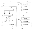
図1はこの発明にかかる画像処理方法および画像処理装置を適用可能な撮像装置の一実施形態を示す図である。この撮像装置1は、試料容器Dに担持された生物試料を撮像対象物として撮像する撮像ユニット10と、撮像ユニット10を制御するとともに撮像された画像に適宜の画像処理を施す制御ユニット20とを備えている。
FIG. 1 is a diagram showing an embodiment of an imaging apparatus to which an image processing method and an image processing apparatus according to the present invention can be applied. The
この撮像装置1が撮像対象物として取り扱う試料は、例えば浅皿型のディッシュのような試料容器Dに担持された培地中で、細胞やその集まりである細胞コロニー(細胞等)が培養されたものである。特に細胞コロニーが球状の集塊をなすとき、このような細胞集塊はスフェロイドとも呼ばれる。培地は例えば軟寒天と培養液とを含み、試料容器Dに所定量注入される。したがって、試料容器Dの内底面には一定の厚みの培地の層が担持される。この培地に細胞が播種され所定の培養条件で培養されることにより、撮像対象物となる生物試料が作成される。
The sample handled by the
撮像ユニット10は、試料容器Dを略水平姿勢に支持するホルダ11と、ホルダ11に支持される試料容器Dの上方に配置され試料容器Dに向けて照明光を照射する照明部13と、ホルダ11に支持される試料容器Dに対して照明部13と反対側、つまり試料容器Dの下方に配置されて試料容器Dを下方から撮像する撮像部15とを備える。撮像部15は、照明部13から照射されて試料容器Dの底面を透過してくる光を受光して、試料容器D内部の試料を撮像する。なお、撮像ユニット10における方向を明示するために、図のようにXYZ直交座標系を設定する。ここで、XY平面は水平面を表し、Z軸は鉛直軸を表す。
The
撮像部15は、図1紙面に垂直なX方向を長手方向として該方向に多数の微小な撮像素子が配列されたリニアイメージセンサ151と、試料容器D底面から出射されてくる透過光をリニアイメージセンサ151の受光面に収束させる結像光学系152と、これらを一体的にY方向に水平移動させる機能とZ方向に昇降移動させる機能とを備えたセンサ駆動部17とを有する。撮像部15は、結像光学系152により集光される試料容器Dからの透過光をリニアイメージセンサで受光しながら試料容器D底面に沿ってY方向に移動する。これにより、試料の二次元画像が取得される。試料の上部から入射し下方に透過する光が撮像部15に受光されて撮像が行われるので、撮像部15による撮像方向は鉛直方向である。なお、図1では撮像光学系152を単一のレンズで代表的に表現しているが、複数のレンズや光学素子の組み合わせにより構成されたものであってもよい。
The
制御ユニット20は、照明部13の動作を制御する照明制御部23、センサ駆動部17を制御して撮像部15を所定の方向に移動させる移動制御部26、撮像部15から出力される画像信号に基づき各種の画像処理を実行する画像処理部25および処理前後の画像データやその他の各種データを記憶保存する記憶部24を備えている。この他に、制御ユニット20は、この撮像装置1を操作するオペレータからの操作指示入力を受け付ける入力受付部21と、システムの動作状況や処理結果等を視覚情報としてオペレータに報知する表示部22とを備えている。
The
次に、上記のように構成された撮像装置1を用いて、試料容器D内の生物試料の全焦点画像を作成する方法について説明する。まず、撮像対象となる生物試料についてその概要を説明する。
Next, a method for creating an omnifocal image of a biological sample in the sample container D using the
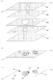
図2は撮像対象となる生物試料の例を示す図である。より具体的には、図2(a)および図2(b)はそれぞれ生物試料を担持する試料容器Dの側面透視図および上面図である。撮像装置1による撮像の対象となる生物試料は、例えばディッシュと称される試料容器Dに注入された培地M中で細胞が三次元培養されたものである。培地Mは試料容器Dに所定の深さまで注入された半固体状であり、例えば軟寒天が用いられる。培地Mには必要に応じ試薬が添加され、細胞が播種されて所定の培養条件で一定期間培養されたものが、生物試料となる。
FIG. 2 is a diagram illustrating an example of a biological sample to be imaged. More specifically, FIG. 2 (a) and FIG. 2 (b) are a side perspective view and a top view of a sample container D carrying a biological sample, respectively. The biological sample to be imaged by the
図では、生物試料の一例として、培地M中で増殖した細胞が固まってスフェロイド(細胞集塊)S1〜S5を形成している例を示している。図に示すように、スフェロイドS1〜S5は培地M内で三次元的な広がりを有し、そのサイズや形状にはばらつきがある。特に細胞が非染色であれば無色透明に近いため、輪郭も必ずしも鮮明なものではない。また培地M中において水平方向(XY方向)および鉛直方向(Z方向)の種々の位置に三次元的に分布している。このようにスフェロイドが三次元的に分布するため、見る方向によってはスフェロイド同士が重なる場合もある。このような特徴を有する生物試料を撮像する場合の問題点について、次に説明する。 In the figure, as an example of the biological sample, cells grown in the medium M are solidified to form spheroids (cell clumps) S1 to S5. As shown in the figure, the spheroids S1 to S5 have a three-dimensional spread in the medium M, and the sizes and shapes thereof vary. In particular, if the cells are unstained, the outline is not necessarily clear because it is almost colorless and transparent. In the culture medium M, it is distributed three-dimensionally at various positions in the horizontal direction (XY direction) and the vertical direction (Z direction). Since spheroids are distributed three-dimensionally in this way, spheroids may overlap each other depending on the viewing direction. Next, problems in imaging a biological sample having such characteristics will be described.
図3は試料を撮像する際に生じうる問題点を模式的に示す図である。図3(a)に示すように、この撮像装置1では試料容器Dの下方に配置された撮像部15により、試料容器Dの底面Dbを介して試料が撮像される。培地Mの深さに対し撮像光学系152の被写界深度が十分に大きくなければ、深さ方向、つまり鉛直方向(Z方向)に分布するスフェロイドの全てを合焦範囲に収めることができない場合がある。
FIG. 3 is a diagram schematically showing problems that may occur when imaging a sample. As shown in FIG. 3A, in this
図3(b)は、例えば撮像光学系152の焦点位置を符号F0で示す深さに設定したときの画像IM0を模式的に示す図である。撮像部15により試料を撮像したとき、撮像光学系152の焦点位置に近い深さに表面が位置するスフェロイドS2は比較的鮮明に撮像される。一方、焦点位置よりも大きく奥側に外れたスフェロイドS1,S4は薄くぼやけた像となり、また焦点位置より手前側に突出するスフェロイドS3も、輪郭が不鮮明となる。撮像光学系152の焦点位置をZ方向に変更することが可能な構成であっても、全てのスフェロイドS1〜S5を合焦範囲に収めることが難しい。
FIG. 3B is a diagram schematically illustrating the image IM0 when, for example, the focal position of the imaging
撮像光学系152の被写界深度を十分大きくすれば、全てのスフェロイドを合焦範囲に収めることは可能となる。しかしながら、被写界深度が培地Mの深さよりも大きい場合、例えば容器壁面などの周囲や背景、培地表面のメニスカスの影響等が画像に映り込むことがあり、画像品質の点では必ずしも好ましくない場合がある。そこで、この撮像装置1では、試料に対する撮像光学系152の焦点位置をZ方向(深さ方向)に多段階に変更設定してその都度撮像する、いわゆるフォーカスブラケット撮像を行う。そして、得られた複数の原画像を画像処理により合成して、種々の深さのスフェロイドに擬似的に焦点の合った全焦点画像を作成する。
If the depth of field of the imaging
図4はフォーカスブラケット撮像により得られる画像の例を説明する図である。一例として、図4(a)に示すように、撮像光学系152の焦点位置をF1〜F5の5段階に変更して撮像した場合を考える。焦点位置F1,F2,F3,F4,F5に対応して、図4(b)に示すように、5枚の原画像IM1,IM2、IM3,IM4,IM5が得られる。ここで、符号Xi,Yiは、実空間における座標と区別して各画像平面における平面座標を表したものである。
FIG. 4 is a diagram illustrating an example of an image obtained by focus bracket imaging. As an example, let us consider a case where imaging is performed by changing the focal position of the imaging
各原画像IM1〜IM5においては、表面が焦点深さに近い位置にあるスフェロイドの像が鮮明に表れる一方、焦点位置から遠いスフェロイドはより不鮮明となる。例えば焦点位置F1に対応する原画像IM1では、表面が焦点位置に近いスフェロイドS1,S4が鮮明に映る一方、焦点位置から遠いスフェロイドS2,S3,S5はぼやけている。また、撮像部15側(容器底面Db側)から見たときスフェロイドS4の手前にスフェロイドS3があるため、スフェロイドS4の像の一部がスフェロイドS3の像により遮蔽されている。
In each of the original images IM1 to IM5, an image of a spheroid whose surface is close to the focal depth appears clearly, while a spheroid far from the focal position becomes unclear. For example, in the original image IM1 corresponding to the focal position F1, spheroids S1 and S4 whose surface is close to the focal position are clearly shown, while spheroids S2, S3 and S5 far from the focal position are blurred. Further, since the spheroid S3 is present in front of the spheroid S4 when viewed from the
また、焦点位置F3に対応する原画像IM3では、焦点面を横切るスフェロイドS5の輪郭が鮮明に映る一方、焦点位置から外れたスフェロイドS1〜S4の像はより不鮮明であり、また平面視において重なり合うスフェロイドS3,S4の境界が不明確となっている。このように、焦点位置に応じて、原画像IM1〜IM5への各スフェロイドS1〜S5の像の表れ方が異なる。以下、このような特徴を有する原画像IM1〜IM5から全焦点画像を作成する2つの具体的な方法について説明する。これらの方法は、制御ユニット20が予め記憶された制御プログラムを実行して装置各部に所定の動作を行わせることにより実現される。
Further, in the original image IM3 corresponding to the focal position F3, the outline of the spheroid S5 that crosses the focal plane is clearly shown, while the images of the spheroids S1 to S4 that are out of the focal position are more unclear and overlap in the plan view. The boundary between S3 and S4 is unclear. Thus, the appearance of the images of the spheroids S1 to S5 on the original images IM1 to IM5 differs depending on the focal position. Hereinafter, two specific methods for creating an omnifocal image from the original images IM1 to IM5 having such characteristics will be described. These methods are realized by causing the
図5は全焦点画像を作成する第1の方法を示すフローチャートである。また、図6は処理の過程で作成される画像を示す図である。最初に、焦点位置が互いに異なる複数の(この例では5枚の)原画像IM1〜IM5が取得される(ステップS101)。より具体的には、撮像部15が焦点位置を変えながら撮像を行うことにより、これらの原画像を取得することができる。
FIG. 5 is a flowchart showing a first method for creating an omnifocal image. FIG. 6 is a diagram showing an image created in the course of processing. First, a plurality of (five in this example) original images IM1 to IM5 having different focal positions are acquired (step S101). More specifically, when the
こうして得られた原画像IM1〜IM5のそれぞれについて、当該原画像を構成する画素各々のエッジ強度が算出される(ステップS102)。エッジ強度を算出する方法としては公知のあるいはそれと同等の種々の方法を用いることができ、例えば4連結画素のエッジフィルタ、差分フィルタ、ラプラシアンフィルタなどを用いることができる。こうしてエッジ強度が求められた画素のうち、比較的大きな値を有するものを「輪郭画素」と称することとする。例えばエッジ強度が予め定められた閾値以上である画素を、輪郭画素とみなすことができる。あるいは、周囲の画素に対するエッジ強度の差が所定値以上である画素を輪郭画素としてもよい。 For each of the original images IM1 to IM5 thus obtained, the edge strength of each pixel constituting the original image is calculated (step S102). As a method for calculating the edge strength, various known methods or equivalent methods can be used. For example, an edge filter of four connected pixels, a difference filter, a Laplacian filter, or the like can be used. Of the pixels whose edge strengths are thus obtained, those having a relatively large value are referred to as “contour pixels”. For example, a pixel whose edge intensity is equal to or greater than a predetermined threshold value can be regarded as a contour pixel. Alternatively, a pixel whose edge intensity difference with respect to surrounding pixels is a predetermined value or more may be used as a contour pixel.
輪郭画素により囲まれる画像内の閉領域が、オブジェクト領域として抽出される。すなわち、輪郭画素が当該オブジェクト領域の輪郭を表すものとされる。スフェロイドが焦点位置から大きく外れていることに起因して輪郭が不鮮明な像は、オブジェクト領域として扱われない。なお、オブジェクト領域は、その輪郭の全てが連続する輪郭画素で構成されるものに限定されず、複数の輪郭画素により実質的に囲まれた領域を含んでよい。例えば、不連続な輪郭画素の間を適宜の補間方法で補間する閉曲線を輪郭とする閉領域、輪郭画素から特定される輪郭と画像の端部とで囲まれる閉領域についても、オブジェクト領域と見なすことができる。 A closed region in the image surrounded by the contour pixels is extracted as an object region. That is, the contour pixel represents the contour of the object region. An image with an unclear outline due to the fact that the spheroid deviates greatly from the focal position is not treated as an object area. Note that the object region is not limited to one in which all the contours are formed by continuous contour pixels, and may include a region substantially surrounded by a plurality of contour pixels. For example, a closed region whose contour is a closed curve that interpolates between discontinuous contour pixels by an appropriate interpolation method, and a closed region surrounded by a contour specified from the contour pixel and the edge of the image is also regarded as an object region. be able to.
また、スフェロイド自体が有する輪郭の不鮮明さに起因して、上記のようにして求められた輪郭画素により特定されるオブジェクト領域が、本来のスフェロイドの広がりよりも小さい領域となる場合があることがわかっている。この問題を解消するために、例えば輪郭画素により囲まれる領域を1画素分拡張させた領域を、オブジェクト領域とするようにしてもよい。 In addition, it is understood that the object area specified by the outline pixel obtained as described above may be an area smaller than the original spread of the spheroid due to the blurred outline of the spheroid itself. ing. In order to solve this problem, for example, a region obtained by expanding a region surrounded by contour pixels by one pixel may be set as an object region.
こうして抽出されたオブジェクト領域に基づき、各原画像からマスク画像が作成される(ステップS103)。具体的には、各原画像に対して、当該原画像において抽出されたオブジェクト領域を透過パターンとするようなマスク画像が作成される。図4(b)に示す原画像IM1〜IM5からは、例えば図6(a)に示すマスク画像M1〜M5が作成される。各マスク画像は、原画像において比較的鮮明な輪郭によって囲まれたオブジェクトの領域の範囲および位置を示す画像である。一の原画像に対し、対応するマスク画像を作用させることで、当該原画像から輪郭の明瞭なオブジェクト領域の画像を切り出すことができる。 Based on the extracted object region, a mask image is created from each original image (step S103). Specifically, for each original image, a mask image is created in which the object area extracted from the original image is a transmission pattern. For example, mask images M1 to M5 shown in FIG. 6A are created from the original images IM1 to IM5 shown in FIG. Each mask image is an image showing the range and position of an object region surrounded by a relatively clear outline in the original image. By applying a corresponding mask image to one original image, an image of an object region having a clear outline can be cut out from the original image.
全焦点画像を作成する第1の方法では、原則的に、これらのマスク画像を対応する原画像に適用して切り出された画像を合成した合成画像が作成される。しかしながら、図4(b)に示したように、1つのスフェロイドの像が複数の原画像に亘って現れることがある。このため、1つのスフェロイドに対応するオブジェクト領域が複数の原画像において抽出され、図6(a)に示すように、マスク画像に現れる透過パターンが画像平面上で重複することがある。その結果、オブジェクト領域が重複する部分では、合成画像に配置すべき画像の候補が複数生じてしまう。このようなマスクの競合を回避するために、抽出された各オブジェクト領域の輪郭の鮮明さを示す指標として輪郭の鮮明度が導入される。 In the first method for creating an omnifocal image, in principle, a composite image is created by synthesizing images cut out by applying these mask images to corresponding original images. However, as shown in FIG. 4B, one spheroid image may appear over a plurality of original images. For this reason, an object region corresponding to one spheroid is extracted from a plurality of original images, and as shown in FIG. 6A, the transmission patterns appearing in the mask image may overlap on the image plane. As a result, a plurality of image candidates to be arranged in the composite image are generated in a portion where the object regions overlap. In order to avoid such mask conflicts, the sharpness of the contour is introduced as an index indicating the sharpness of the contour of each extracted object region.
鮮明度Shについては、例えば以下のように各オブジェクト領域の輪郭のエッジ強度を用いて定義することができる。オブジェクト領域が鮮明な輪郭を有していれば、その画像においてオブジェクト領域の内部と外部との境界である輪郭のエッジ強度が高くなると考えられる。このことから、輪郭のエッジ強度を適宜に正規化した値をもって鮮明度を表すことが可能である。例えば次のように、輪郭におけるエッジ強度に対応する画素値を有する画素を仮想的に設定し、当該仮想画素の画素値が表す光学濃度の値を鮮明度の値として用いることができる。 The definition Sh can be defined by using the edge strength of the contour of each object area as follows, for example. If the object area has a clear outline, the edge strength of the outline that is the boundary between the inside and the outside of the object area in the image is considered to be high. From this, it is possible to express the sharpness with a value obtained by appropriately normalizing the edge strength of the contour. For example, as described below, a pixel having a pixel value corresponding to the edge intensity in the contour can be virtually set, and an optical density value represented by the pixel value of the virtual pixel can be used as the sharpness value.
続いて、こうして求められる仮想画素についてエッジ強度を算出する。エッジ強度を求める処理としては種々のエッジ検出フィルタ処理を適用することができる。例えばSobelフィルタ、差分フィルタ、Prewittフィルタ、Robertsフィルタ、ラプラシアンフィルタ等の各種フィルタ処理を好適に適用することが可能である。ここではエッジ検出フィルタの例としてSobelフィルタ演算を適用した場合について説明する。 Subsequently, the edge strength is calculated for the virtual pixel thus obtained. Various edge detection filter processes can be applied as the process for obtaining the edge strength. For example, various filter processes such as a Sobel filter, a difference filter, a Prewitt filter, a Roberts filter, and a Laplacian filter can be suitably applied. Here, a case where the Sobel filter calculation is applied as an example of the edge detection filter will be described.
各仮想画素の輝度値に対して、(3×3)のSobelフィルタ演算を行う。画像の水平方向(x方向)および垂直方向(y方向)におけるSobelフィルタ演算の係数行列については、それぞれ次式により表すことができる。 A (3 × 3) Sobel filter operation is performed on the luminance value of each virtual pixel. The coefficient matrix of the Sobel filter calculation in the horizontal direction (x direction) and the vertical direction (y direction) of the image can be expressed by the following equations, respectively.

また、仮想画素ごとに求めたx方向での演算結果をSx、y方向での演算結果をSyにより表すとき、当該仮想画素のエッジ強度Seについては次式により表すことができる。 Further, when the calculation result in the x direction obtained for each virtual pixel is represented by Sx, and the calculation result in the y direction is represented by Sy, the edge intensity Se of the virtual pixel can be represented by the following equation.
このようにして求められた値Seは、他の画素に対する当該画素のエッジ強度を相対的に表す数値であり、計算の原理上、輝度値のスケールが4倍に強調されたものとなっている。したがって、エッジ強度Seの値を4で除することにより、画素の輝度値と同じスケールの数値範囲に正規化されたエッジ強度を得ることができる。1つのオブジェクト領域に対応する仮想画素各々のエッジ強度Seの平均値をSaとすると、値(Sa/4)は、1つのオブジェクト領域の輪郭が有する平均的な正規化エッジ強度を表し、これが当該オブジェクト領域の輪郭の鮮明さを指標する値となる。 The value Se thus obtained is a numerical value that relatively represents the edge intensity of the pixel with respect to other pixels, and the scale of the luminance value is emphasized four times on the principle of calculation. . Therefore, by dividing the value of the edge strength Se by 4, it is possible to obtain an edge strength normalized to a numerical range of the same scale as the luminance value of the pixel. When the average value of the edge strength Se of each virtual pixel corresponding to one object region is Sa, the value (Sa / 4) represents the average normalized edge strength of the contour of one object region, This is a value indicating the sharpness of the outline of the object area.
ただし、オブジェクト領域を取り巻く背景領域の濃度や照明条件のばらつき(シェーディング)の影響を排除する必要がある。そこで、仮想画素を上記のようにして求められる正規化エッジ強度(Sa/4)を輝度値として有する画素に置き換えたさらに仮想的な画像を考え、当該画像における仮想画素の光学濃度を、当該オブジェクト領域の鮮明度Shとして定義する。すなわち次式:
Sh=log10{Is/(Is−Sa/4)}
により鮮明度Shを定義する。ここで、値Isはオブジェクト領域の背景領域の輝度平均値であり、例えば当該オブジェクト領域を取り囲む所定幅の周囲領域の輝度の平均値や、当該原画像においてオブジェクト領域とされなかった領域全体の輝度の平均値などで表すことができる。背景領域の輝度を加味した光学濃度の次元で示すことにより、オブジェクト領域の背景領域や照明ばらつきの影響を排して各オブジェクト領域の鮮明度Shを客観的に表し、異なるオブジェクト領域間でも比較可能な数値として表すことが可能となる。
However, it is necessary to eliminate the influence of the density of the background area surrounding the object area and the variation (shading) of illumination conditions. Therefore, a virtual image in which the virtual pixel is replaced with a pixel having the normalized edge intensity (Sa / 4) obtained as described above as a luminance value is considered, and the optical density of the virtual pixel in the image is determined as the object. This is defined as the sharpness Sh of the region. That is:
Sh = log 10 {Is / (Is-Sa / 4)}
Defines the definition Sh. Here, the value Is is the average brightness value of the background area of the object area. For example, the average brightness value of the surrounding area having a predetermined width surrounding the object area, or the brightness of the entire area that is not set as the object area in the original image. It can be expressed by the average value of. By showing the density of the optical density in consideration of the brightness of the background area, the object area clearly shows the definition Sh of the object area, eliminating the influence of the background area and illumination variations, and can be compared between different object areas. It can be expressed as a simple numerical value.
本願発明者の知見によれば、このようにオブジェクト領域の輪郭の鮮明度Shを定義した場合、原画像において輪郭が明瞭に視認されるスフェロイドに対応するオブジェクト領域に対して鮮明度Shが1に近い値となる一方、見た目の輪郭の不鮮明さが増すほど鮮明度Shが0に近づく値となることが確認された。すなわち、上記定義により、オブジェクト領域の輪郭の鮮明さを定量的に表現することができる。 According to the knowledge of the present inventor, when the sharpness Sh of the contour of the object region is defined in this way, the sharpness Sh is set to 1 for the object region corresponding to the spheroid whose contour is clearly visible in the original image. On the other hand, it was confirmed that the sharpness Sh becomes a value closer to 0 as the unclearness of the apparent outline increases. That is, by the above definition, the sharpness of the contour of the object region can be expressed quantitatively.
なお、エッジ強度に基づき抽出されたオブジェクト領域であっても、この段階で算出される鮮明度が相当に低い値となる場合があり得る。エッジ強度による評価のみでは、例えば高濃度であるが輪郭の不鮮明な(つまり非合焦状態の)像をオブジェクト領域と判断してしまうことがある。したがって、オブジェクト領域とされた領域であっても、輪郭の鮮明度が不足するものについては、以後の処理においてオブジェクト領域としての扱いから除外するようにしてもよい。 Even in the object region extracted based on the edge strength, the sharpness calculated at this stage may be a considerably low value. With only the evaluation based on the edge strength, for example, an image with a high density but a sharp outline (that is, in an out-of-focus state) may be determined as an object region. Therefore, even if the region is an object region, the region that lacks the sharpness of the contour may be excluded from the treatment as the object region in the subsequent processing.
各原画像の間で重複するオブジェクト領域については、それらの鮮明度に基づいてマスクの競合が解決される。すなわち、複数のマスク画像において透過パターンが(部分的に)重複するとき、言い換えれば、複数の原画像のそれぞれで抽出されたオブジェクト領域のうち少なくとも一部が画像平面上で同一座標位置を占めるとき、重複部分については、輪郭の鮮明度Shが最も高いオブジェクト領域が優先される。 For object regions that overlap between original images, mask conflicts are resolved based on their sharpness. That is, when the transmission patterns overlap (partially) in a plurality of mask images, in other words, when at least some of the object regions extracted in each of the plurality of original images occupy the same coordinate position on the image plane For the overlapping portion, the object region having the highest contour definition Sh is prioritized.
上記したように、オブジェクト領域の輪郭の鮮明度は、当該オブジェクト領域に対応するスフェロイドの輪郭の明瞭さを表している。したがって、同一スフェロイドが複数の原画像に映り込むことによってオブジェクト領域が重複する場合、そのうち輪郭の鮮明度が最も高い原画像が切り出されるようにすることで、より輪郭が明瞭な、つまりより合焦状態に近い像が合成画像に配置されることが可能となる。 As described above, the sharpness of the outline of the object area represents the clarity of the outline of the spheroid corresponding to the object area. Therefore, when the object area overlaps when the same spheroid is reflected in a plurality of original images, the original image with the highest sharpness of the outline is cut out so that the outline is clearer, that is, the in-focus state is more focused. An image close to the state can be arranged in the composite image.
図6(b)は各マスク画像M1〜M5を重ね合わせた状態を示しており、図において斜線を付した領域においてマスクの競合が生じている。これらの領域のそれぞれでは、重複するオブジェクト領域の輪郭の鮮明度Shが相互に比較され、鮮明度が最も大きいオブジェクト領域が有効とされる。言い換えれば、鮮明度が最も大きいオブジェクト領域が属するマスク画像の透過パターンが維持され、それ以外のマスク画像の透過パターンは塗りつぶされる。したがって、重複部分では、オブジェクト領域の輪郭の鮮明度Shが高い方の原画像の内容が合成画像に反映されることになる。 FIG. 6B shows a state in which the mask images M1 to M5 are superimposed, and mask competition occurs in the hatched area in the figure. In each of these areas, the sharpness Sh of the contours of the overlapping object areas is compared with each other, and the object area having the highest sharpness is validated. In other words, the transmission pattern of the mask image to which the object region having the highest definition belongs is maintained, and the transmission patterns of the other mask images are filled. Therefore, in the overlapping portion, the content of the original image having the higher sharpness Sh of the outline of the object region is reflected in the composite image.
なお、複数の原画像間でオブジェクト領域が互いに重複する部分がある場合、当該重複する部分についてのみマスク競合の解決が図られる。つまり、他のオブジェクト領域と部分的に重複するオブジェクト領域では、重複部分については他のオブジェクト領域との比較によって有効とするか否かが判断される一方、重複部分以外は有効なものとされ、当該部分から切り出された原画像の内容が合成画像に配置される。 Note that if there are portions where the object regions overlap each other among a plurality of original images, the mask conflict is resolved only for the overlapping portions. In other words, in an object area that partially overlaps with another object area, it is determined whether or not the overlapping part is valid by comparison with the other object area, while other than the overlapping part is valid. The contents of the original image cut out from the portion are arranged in the composite image.
図6(c)は、上記のようにして各原画像から切り出されたオブジェクト領域を一の画像平面上の対応する位置に配置することにより作成される合成画像Is1の例を示している。各原画像から抽出されるオブジェクト領域の画像のうち、他のオブジェクト領域との重複がない部分についてはその部分の原画像が切り出されて合成画像Is1に配置される。また、原画像間でオブジェクト領域が重複する部分がある場合には、当該部分については、重複オブジェクト領域のうち最も輪郭の鮮明度Shが高いオブジェクト領域が属する原画像から画像が切り出されて合成画像Is1に配置される。 FIG. 6C shows an example of the composite image Is1 created by arranging the object region cut out from each original image as described above at a corresponding position on one image plane. Among the image of the object area extracted from each original image, the original image of that part is cut out and arranged in the composite image Is1 for a part that does not overlap with other object areas. In addition, when there is a portion where the object region overlaps between the original images, an image is cut out from the original image to which the object region having the highest contour sharpness Sh belongs among the overlapping object regions. Arranged at Is1.
これにより、各スフェロイドS1〜S5のそれぞれを最も鮮明に撮像した領域が複数の原画像IM1〜IM5の中から個別に切り出されて合成画像Is1が作成されることになる。そのため、この方法によれば、試料中で三次元的に分布するスフェロイドS1〜S5のそれぞれに焦点の合った全焦点画像を疑似的に作成することが可能である。この場合、画像平面においてある程度の広がりを有する領域が切り出されて合成されるので、原画像におけるスフェロイド表面のテクスチャが合成画像においても保存されている。 Thereby, the area | region which imaged each of each spheroid S1-S5 most clearly is cut out separately from several original image IM1-IM5, and the synthesized image Is1 is produced. Therefore, according to this method, it is possible to artificially create an omnifocal image focused on each of the spheroids S1 to S5 distributed three-dimensionally in the sample. In this case, since an area having a certain extent on the image plane is cut out and synthesized, the texture of the spheroid surface in the original image is also saved in the synthesized image.
また、オブジェクト領域の重複がある場合、重複する部分とそれ以外の部分とが個別に処理される。このため、深さ方向に異なる位置にあるスフェロイドが画像上で重なっていても、これらのそれぞれについて個別に鮮明な画像を選出することが可能である。図6(c)の合成画像Is1においては、スフェロイドS3,S4の像がこのケースに相当している。 When there are overlapping object areas, the overlapping part and the other part are processed individually. For this reason, even if spheroids at different positions in the depth direction overlap on the image, it is possible to individually select clear images for each of these. In the synthesized image Is1 in FIG. 6C, images of spheroids S3 and S4 correspond to this case.
なお、試料中で比較的大きな体積を有し、水平方向(XY方向)および深さ方向(Z方向)に大きな広がりを有するスフェロイドでは、当該スフェロイドの一部領域が一の原画像において合焦し、他の一部領域が他の原画像において合焦するというケースもあり得る。このような場合にも、複数の原画像から切り出された鮮明な部分画像の組み合わせで1つのスフェロイドが表現されるため、スフェロイド全体に焦点が合った画像を得ることができる。図6(c)の合成画像Is1においては、スフェロイドS3,S5の像がこのケースに相当している。 In a spheroid having a relatively large volume in the sample and having a large spread in the horizontal direction (XY direction) and the depth direction (Z direction), a partial region of the spheroid is focused on one original image. There may be a case where another partial region is focused on another original image. Even in such a case, since one spheroid is expressed by a combination of clear partial images cut out from a plurality of original images, an image focused on the entire spheroid can be obtained. In the composite image Is1 in FIG. 6C, images of spheroids S3 and S5 correspond to this case.
具体的な処理内容について、図5を参照して説明する。上記したように、各原画像から抽出されたオブジェクト領域について、輪郭の鮮明度が求められる(ステップS104)。なお、ステップS102からS104までの処理は、複数の原画像IM1〜IM5のそれぞれで独立して実行される。これに対し、ステップS105以降の処理は、複数の原画像の同一座標位置にある画素間での演算となる。 Specific processing contents will be described with reference to FIG. As described above, the sharpness of the outline is obtained for the object region extracted from each original image (step S104). Note that the processing from steps S102 to S104 is performed independently for each of the plurality of original images IM1 to IM5. On the other hand, the processing after step S105 is calculation between pixels at the same coordinate position of a plurality of original images.
続いて、画像平面における1つの画素位置が選出され(ステップS105)、当該位置がいずれかのマスクに該当するか否かが判断される(ステップS106)。当該位置が少なくとも1つの原画像のオブジェクト領域に含まれるときマスクに該当すると判断され(ステップS106においてYES)、続いてその重複が判断される(ステップS107)。当該位置が2以上の原画像のオブジェクト領域に含まれるとき、当該位置においてオブジェクト領域が重複しているということができる。 Subsequently, one pixel position on the image plane is selected (step S105), and it is determined whether or not the position corresponds to any mask (step S106). When the position is included in the object area of at least one original image, it is determined that the position corresponds to the mask (YES in step S106), and then the overlap is determined (step S107). When the position is included in the object areas of two or more original images, it can be said that the object areas overlap at the positions.
オブジェクト領域の重複があるとき(ステップS107においてYES)、重複するオブジェクト領域間で輪郭の鮮明度Shが評価され、最も鮮明度が高いオブジェクト領域の属する原画像から、当該画素位置に配置すべき画素が選択される(ステップS108)。つまり、ここで選択された画素の画素値が、合成画像における当該位置の画素が有するべき画素値とされる。オブジェクト領域の重複がない(ステップS107においてNO)、つまり当該画素位置に対応するオブジェクト領域が1つの原画像のみにあるとき、当該原画像の画素が、該画素位置に配置すべき画素として選択される(ステップS109)。 When there is an overlap of the object areas (YES in step S107), the sharpness Sh of the contour is evaluated between the overlapping object areas, and the pixel to be arranged at the pixel position from the original image to which the object area having the highest definition belongs. Is selected (step S108). That is, the pixel value of the pixel selected here is the pixel value that the pixel at the position in the composite image should have. When there is no overlapping of the object areas (NO in step S107), that is, when the object area corresponding to the pixel position is in only one original image, the pixel of the original image is selected as the pixel to be arranged at the pixel position. (Step S109).
当該画素位置がいずれのマスクにも該当しないとき(ステップS106においてNO)、当該画素位置はスフェロイドが存在しない背景領域に含まれるということができる。そこで、いずれかの原画像から、背景を表すものとして適当な画素が選択される(ステップS110)。 When the pixel position does not correspond to any of the masks (NO in step S106), it can be said that the pixel position is included in the background region where no spheroid exists. Therefore, an appropriate pixel is selected from any of the original images as representing the background (step S110).
スフェロイドの背景を表す画素としては、例えば、当該画素位置に対応する各原画像のうち最も輝度の高いものを用いることができる。一般的に背景領域はスフェロイドの領域よりも高輝度であるが、非合焦画像ではスフェロイド周縁部のボケにより本来の背景よりも輝度が低下することがあり得る。同一位置で最も輝度の高い画素を採用することで、本来の背景の輝度を合成画像に反映させることができる。同様の考え方から、例えば、オブジェクト領域内の画素を除外した画素の輝度平均値が最も高い原画像の画素を採用するようにしてもよい。 As the pixel representing the background of the spheroid, for example, a pixel having the highest luminance among the original images corresponding to the pixel position can be used. In general, the background area has higher brightness than the spheroid area, but the brightness of the unfocused image may be lower than that of the original background due to blurring at the periphery of the spheroid. By adopting the pixel having the highest luminance at the same position, the original background luminance can be reflected in the synthesized image. From the same concept, for example, the pixel of the original image having the highest luminance average value of the pixels excluding the pixels in the object area may be adopted.
また、原画像のうち1つを予め基準画像として設定しておき、該基準画像の画素を背景としてもよい。例えば、深さ方向において焦点位置が中庸である一の原画像(この例では原画像IM3)を基準画像とすることができる。スフェロイドの背景の状態がさほど重視されない用途では、このような方法が簡単である。 Further, one of the original images may be set as a reference image in advance, and the pixels of the reference image may be used as the background. For example, one original image (in this example, the original image IM3) having a focus position in the depth direction can be used as the reference image. This method is simple for applications where the background state of the spheroid is not so important.
以上のようにして、現在の画素位置の画素がいずれかの原画像から選出される。こうして選出された画素の画素値を画像平面上の当該画素位置に割り付けることで(ステップS111)、合成画像Is1における当該位置の画素値が決定される。全ての画素位置について上記処理が実行されることにより(ステップS112)、合成画像Is1を構成する全ての画素の画素値が決定される。こうして作成された合成画像Is1は、上記した通り、焦点位置の異なる複数の原画像から合成された全焦点画像となる。 As described above, the pixel at the current pixel position is selected from one of the original images. By assigning the pixel value of the pixel thus selected to the pixel position on the image plane (step S111), the pixel value at the position in the composite image Is1 is determined. By executing the above process for all pixel positions (step S112), the pixel values of all the pixels constituting the composite image Is1 are determined. The composite image Is1 thus created is an omnifocal image synthesized from a plurality of original images having different focal positions as described above.
なお、上記では各原画像からどのようにして有効な領域が切り出されるかを説明するためにマスク画像の概念を用いているが、各原画像でのオブジェクト領域の特定および原画像間での重複の判断が適切になされて画像領域の切り出しを行うことができれば足り、処理の過程で実際にマスク画像を作成することを必須とするものではない。 In the above, the concept of a mask image is used to explain how an effective area is cut out from each original image. However, the object area in each original image is specified and overlapped between the original images. Therefore, it is sufficient to make an appropriate determination and to cut out an image region, and it is not essential to actually create a mask image in the process.
ここまで説明した全焦点画像作成の第1の方法では、各原画像内でオブジェクト領域を抽出し、原画像間でオブジェクト領域の重複がある場合に原画像間での鮮明度の比較が行われる。一方、次に説明する第2の方法では、焦点位置を異ならせて撮像された複数の原画像から三次元空間における各スフェロイドの輪郭を特定し、特定された輪郭内にいずれかの原画像の画像内容を配置することにより、全焦点画像が作成される。 In the first method for creating an omnifocal image described so far, an object region is extracted from each original image, and when there is an overlap of the object region between the original images, the definition is compared between the original images. . On the other hand, in the second method described below, the contour of each spheroid in the three-dimensional space is specified from a plurality of original images picked up at different focal positions, and one of the original images is included in the specified contour. By placing the image content, an omnifocal image is created.
図7は全焦点画像を作成する第2の方法を示すフローチャートである。また、図8はこの処理の原理を説明する図である。最初に、焦点位置が互いに異なる複数の(この例では5枚の)原画像IM1〜IM5が取得される(ステップS201)。より具体的には、撮像部15が焦点位置を変えながら撮像を行うことにより、これらの原画像を取得することができる。また、こうして得られた原画像IM1〜IM5のそれぞれについて、当該原画像を構成する画素各々のエッジ強度が適宜の算出方法により算出される(ステップS202)。
FIG. 7 is a flowchart showing a second method for creating an omnifocal image. FIG. 8 is a diagram for explaining the principle of this processing. First, a plurality (five in this example) of original images IM1 to IM5 having different focal positions are acquired (step S201). More specifically, when the
続いて、画像平面における1つの画素位置が選出され(ステップS203)、当該位置に対応する画素のエッジ強度が原画像間で比較され、エッジ強度が最大の画素が選出される(ステップS204)。このとき、選出された画素がどの原画像に属するかが併せて記憶される。この処理が、全ての画素位置について行われる(ステップS205)。 Subsequently, one pixel position on the image plane is selected (step S203), the edge intensity of the pixel corresponding to the position is compared between the original images, and the pixel with the maximum edge intensity is selected (step S204). At this time, the original image to which the selected pixel belongs is also stored. This process is performed for all pixel positions (step S205).
スフェロイドの輪郭の位置に対応する画素位置では、三次元的に広がるスフェロイドの輪郭を当該画素位置で最も鮮明に捉えた画素が上記処理により選出されることが期待される。したがって、このようにして選出された画素を一の画像平面に投影したとき、エッジ強度が比較的大きい画素を結んでなる輪郭は、図8(a)に示すように、十分に大きい被写界深度を有する撮像系により各スフェロイドを撮像したときのスフェロイドの輪郭に相当するものとなる。選出された画素を一の画像平面に投影した画像において、エッジ強度が比較的大きい、例えば所定の閾値以上である画素のみが抽出されて輪郭画像Irが作成される(ステップS206)。 In the pixel position corresponding to the position of the spheroid contour, it is expected that the pixel that most clearly captures the three-dimensionally expanded spheroid contour at the pixel position is selected by the above processing. Therefore, when the pixels selected in this way are projected onto one image plane, the contour formed by connecting pixels having a relatively large edge strength is a sufficiently large object field as shown in FIG. This corresponds to the contour of the spheroid when each spheroid is imaged by an imaging system having a depth. In the image obtained by projecting the selected pixels onto one image plane, only pixels having a relatively high edge strength, for example, a predetermined threshold value or more, are extracted to create the contour image Ir (step S206).
1つのスフェロイドが複数の原画像で合焦する場合については次のように考えることができる。図8(b)に示すように、深さ方向に広がりを有するスフェロイドSの一部が一の原画像IMaにおいて合焦し、他の一部が他の原画像IMbにおいて合焦している場合を考える。原画像IMaにおいて合焦するスフェロイドSの輪郭上の一点を符号P1aにより表す。点P1aに位置する画素は、比較的高いエッジ強度を有すると考えられる。 The case where one spheroid is focused on a plurality of original images can be considered as follows. As shown in FIG. 8B, when a part of the spheroid S having a spread in the depth direction is in focus in one original image IMa and the other part is in focus in another original image IMb think of. One point on the contour of the spheroid S to be focused on in the original image IMa is represented by reference symbol P1a. The pixel located at the point P1a is considered to have a relatively high edge strength.
一方、画像平面において点P1aと同一位置に対応する原画像IMb上の点P1bでは、スフェロイド表面に合焦していないため、当該位置の画素のエッジ強度は低い。このため、輪郭画像Ir上の対応する点P1rでは、点P1aにおけるエッジ強度が採用される。 On the other hand, since the point P1b on the original image IMb corresponding to the same position as the point P1a on the image plane is not focused on the spheroid surface, the edge intensity of the pixel at the position is low. For this reason, the edge strength at the point P1a is adopted at the corresponding point P1r on the contour image Ir.
また、原画像IMbにおいて合焦するスフェロイドSの輪郭上の点P2bの画素は、対応する原画像IMa上の点P2aの画素よりも高いエッジ強度を有する。したがって、輪郭画像Ir上の対応する点P2rでは、点P2bにおけるエッジ強度が採用される。 Further, the pixel at the point P2b on the contour of the spheroid S that is in focus in the original image IMb has a higher edge strength than the pixel at the point P2a on the corresponding original image IMa. Therefore, the edge strength at the point P2b is employed at the corresponding point P2r on the contour image Ir.
輪郭画像Irでは、比較的大きいエッジ強度を有する画素が輪郭画素とされ、これが各スフェロイドの輪郭の位置を表すものとされる。すなわち、輪郭画像Irにおいて輪郭画素により実質的に囲まれた閉領域に対応する合成画像上の領域が、合成画像におけるスフェロイドの領域とされる。なお、スフェロイド自体の輪郭の不鮮明さに起因して本来のスフェロイドよりも小さい領域が特定される問題に対応するため、例えば輪郭画素により囲まれる閉領域を1画素分拡張させた領域をスフェロイドの領域とするようにしてもよい。 In the contour image Ir, a pixel having a relatively large edge strength is a contour pixel, and this represents the position of the contour of each spheroid. That is, a region on the composite image corresponding to the closed region substantially surrounded by the contour pixels in the contour image Ir is set as a spheroid region in the composite image. In order to cope with the problem of specifying a region smaller than the original spheroid due to the unclear outline of the spheroid itself, for example, a region obtained by expanding a closed region surrounded by contour pixels by one pixel is a spheroid region. You may make it.
図7に戻って、輪郭画像により特定される閉領域の1つが選出され(ステップS207)、当該閉領域の評価スコアが原画像ごとにカウントされる(ステップS208)。評価スコアは、各々の原画像において当該閉領域内に含まれる画素のうち、ステップS204においてエッジ強度が最大とされた画素の数をカウントしたものである。ステップS204では、同一位置に対応する各原画像の画素のうちエッジ強度が最大、つまり最も鮮明と見なせる画素が選出される。こうして選出される画素を閉領域内に多く含む原画像ほど、当該閉領域のより鮮明な像を含むものと考えることができる。 Returning to FIG. 7, one of the closed areas specified by the contour image is selected (step S207), and the evaluation score of the closed area is counted for each original image (step S208). The evaluation score is obtained by counting the number of pixels whose edge intensity is maximized in step S204 among the pixels included in the closed region in each original image. In step S204, the pixel having the maximum edge strength, that is, the pixel that can be regarded as the clearest is selected from the pixels of each original image corresponding to the same position. It can be considered that the original image including more pixels selected in this manner includes a clearer image of the closed region.
そこで、当該閉領域については、当該閉領域の評価スコアが最大の原画像から切り出した画像が合成画像に割り付けられるようにする(ステップS209)。輪郭画像において閉領域が複数存在する場合、それらの全てについて同様に処理することで(ステップS210)、輪郭画素により特定される閉領域への画像の割り付けが完了する。そして、閉領域以外の領域については適宜の背景画素を割り付けることで(ステップS211)、合成画像が作成される。背景画素の選出方法については、上記した第1の方法と同様にすることができる。 Therefore, for the closed region, an image cut out from the original image having the maximum evaluation score of the closed region is assigned to the synthesized image (step S209). When there are a plurality of closed regions in the contour image, all of them are processed in the same manner (step S210), and the assignment of the image to the closed region specified by the contour pixel is completed. Then, an appropriate background pixel is assigned to a region other than the closed region (step S211), and a composite image is created. The background pixel selection method can be the same as the first method described above.
図9は第2の方法により作成される合成画像の例を示す図である。全焦点画像の作成の第2の方法で作成される合成画像Is2では、まずスフェロイドの輪郭が深さ方向も含めて特定される。そして、特定された輪郭の内部にいずれかの原画像から切り出された画像を割り付けられる。輪郭の内部に割り付けるべき画像は各原画像から切り出すことができるが、それらの画像のうち、評価スコアが最も高い、つまりエッジ強度の高い画素を最も多く含む画像が選択されて合成画像に割り付けられる。これにより、当該輪郭に囲まれる領域において最も鮮明な原画像の画像内容が合成画像に反映される。したがって、合成画像Is2は、深さ方向に位置の異なるスフェロイドS1〜S5に対応する全焦点画像となっている。 FIG. 9 is a diagram illustrating an example of a composite image created by the second method. In the composite image Is2 created by the second method of creating an omnifocal image, first, the spheroid contour is specified including the depth direction. Then, an image cut out from any of the original images can be allocated inside the specified contour. An image to be assigned to the inside of the contour can be cut out from each original image, but among those images, the image having the highest evaluation score, that is, the pixel having the highest edge strength is selected and assigned to the synthesized image. . As a result, the image content of the clearest original image in the region surrounded by the contour is reflected in the composite image. Therefore, the composite image Is2 is an omnifocal image corresponding to the spheroids S1 to S5 having different positions in the depth direction.
なお、この方法では、スフェロイドの輪郭検出が水平方向成分に加え深さ方向成分にも亘って行われるため、複数のスフェロイドが深さ方向に重なっている場合にこれらを分離することができない場合がある。図9の例では、スフェロイドS3とスフェロイドS4とが一体のものとして扱われている。その一方、スフェロイドの輪郭をより明瞭に特定するという点では本方法が有効である。特に、深さ方向への広がりを有するスフェロイドの輪郭を、被写界深度の大きい撮像系で撮像した場合と同様の明瞭さで特定するという用途に対し、本方法が好適であるといえる。 In this method, since the contour detection of the spheroid is performed over the depth direction component in addition to the horizontal direction component, it may not be possible to separate them when a plurality of spheroids overlap in the depth direction. is there. In the example of FIG. 9, the spheroid S3 and the spheroid S4 are handled as a single body. On the other hand, this method is effective in that the outline of the spheroid is specified more clearly. In particular, it can be said that the present method is suitable for an application in which the contour of a spheroid having a spread in the depth direction is specified with the same clarity as when an image pickup system having a large depth of field is picked up.
以上説明したように、上記実施形態においては、図5および図7に示す全焦点画像作成方法が、本発明の「画像処理方法」に相当している。図5の処理では、ステップS101、S102〜S103およびS105〜S112が、それぞれ本発明の「画像取得工程」、「領域抽出工程」および「画像合成工程」に相当する。図7の処理では、ステップS201、S202〜S205、S206〜S211が、それぞれ本発明の「画像取得工程」、「画素選出工程」および「画像合成工程」に相当する。 As described above, in the above embodiment, the omnifocal image creation method shown in FIGS. 5 and 7 corresponds to the “image processing method” of the present invention. In the processing of FIG. 5, steps S101, S102 to S103 and S105 to S112 correspond to the “image acquisition process”, “region extraction process” and “image composition process” of the present invention, respectively. In the process of FIG. 7, steps S201, S202 to S205, and S206 to S211 correspond to the “image acquisition process”, “pixel selection process”, and “image composition process” of the present invention, respectively.
また、上記実施形態では、撮像装置1が本発明の「画像処理装置」に相当している。撮像装置1においては、撮像ユニット10が本発明の「画像取得手段」として機能し、撮像部15は本発明の「撮像部」として、センサ駆動部17が本発明の「焦点設定部」として機能している。また制御ユニット20、特に画像処理部25が本発明の「画像処理手段」として機能している。
In the above embodiment, the
なお、本発明は上記した実施形態に限定されるものではなく、その趣旨を逸脱しない限りにおいて上述したもの以外に種々の変更を行うことが可能である。例えば、上記した実施形態の撮像装置1は、全焦点画像の作成に用いられる原画像を撮像するための撮像ユニット10を有するものである。
The present invention is not limited to the above-described embodiment, and various modifications other than those described above can be made without departing from the spirit of the present invention. For example, the
しかしながら、本発明にかかる画像処理装置および画像処理方法においては、撮像対象物を撮像するという動作は必須の構成ではない。すなわち、原画像を撮像するための撮像装置と、画像処理を実行して全焦点画像を作成する画像処理装置とが別体として構成されてもよい。例えば本発明にかかる画像処理装置は、外部の撮像装置で撮像された原画像を例えば通信回線を介して受信し、当該原画像を用いて画像処理を行う構成であってもよい。 However, in the image processing apparatus and the image processing method according to the present invention, the operation of imaging the imaging object is not an essential configuration. That is, an imaging device for capturing an original image and an image processing device that executes image processing to create an omnifocal image may be configured separately. For example, the image processing apparatus according to the present invention may be configured to receive an original image captured by an external imaging apparatus via, for example, a communication line and perform image processing using the original image.
例えば、上記実施形態の入力受付部21を外部装置から画像データを受信する機能を有するものとして、外部の撮像装置やデータストレージ等から与えられる画像データを用いて制御ユニット20が上記処理を実行するようにしてもよい。この場合、入力受付部21が本発明の「画像取得手段」として機能することになる。
For example, assuming that the
すなわち、制御ユニット20単体でも、本発明の「画像処理装置」としての機能を実現することが可能である。そして、制御ユニット20の構成は、一般的なパーソナルコンピューターやワークステーション等の情報処理機器と変わらず、また処理内容も、適宜のソフトウェアが実装されることにより、これらの機器によって実現可能なものである。したがって、上記した画像処理をこれらの情報処理機器に実行させるための制御プログラムとして、本発明が提供されてもよい。このような制御プログラムを例えば既存の顕微鏡装置の制御コンピューターに実装することで、当該顕微鏡装置を本発明の画像処理装置として機能させることも可能となる。
That is, the function as the “image processing apparatus” of the present invention can be realized by the
また、上記実施形態では撮像部15を昇降させることで焦点位置を変更設定しているが、これに代えて、例えば試料容器Dを昇降させたり、撮像光学系の焦点調整機能を用いて焦点位置の変更を行うようにしてもよい。また、上記実施形態ではリニアイメージセンサ151を有する撮像部15を撮像対象物に対し走査移動させることで撮像対象物の二次元画像を得ているが、走査移動を伴わずに二次元画像を撮像する機能を有するエリアイメージセンサを用いて撮像が行われてもよい。また、顕微光学系と組み合わせた撮像が行われてもよい。
In the above embodiment, the focal position is changed and set by moving the
以上、具体的な実施形態を例示して説明してきたように、この発明の画像処理方法の第1の態様では、輪郭の鮮明さは、例えば当該輪郭におけるエッジ強度に対応する画素値を有する画素の光学濃度により表すことができる。さらにこの場合、輪郭の鮮明さは、輪郭に対応する各画素について画素の輝度値に基づきエッジ検出フィルタ演算によりそれぞれ求めたエッジ強度の平均値をSa、当該輪郭により特定されるオブジェクト領域に隣接する周囲領域の画素の輝度の平均値をIsとしたとき、次式:
Sh=log10{Is/(Is−Sa/4)}
の左辺Shにより表すことができる。このような手法により、定性的な輪郭の鮮明さを定量的に表現することができ、複数の原画像から抽出されるオブジェクト領域の比較を客観的かつ一義的に行うことが可能となる。
As described above, the specific embodiment has been illustrated and described. In the first aspect of the image processing method of the present invention, the sharpness of the contour is, for example, a pixel having a pixel value corresponding to the edge strength in the contour. It can be expressed by the optical density. Further, in this case, the sharpness of the contour is determined by calculating the average value of the edge strength obtained by the edge detection filter calculation based on the luminance value of the pixel for each pixel corresponding to the contour, and adjacent to the object area specified by the contour. When the average luminance value of the pixels in the surrounding area is Is, the following formula:
Sh = log 10 {Is / (Is-Sa / 4)}
Can be represented by the left side Sh. With such a method, the qualitative outline sharpness can be expressed quantitatively, and object regions extracted from a plurality of original images can be compared objectively and uniquely.
また例えば、複数の原画像の各々において、輪郭画素を輪郭とする領域のうち輪郭の鮮明さが所定値以上であるものをオブジェクト領域とするようにしてもよい。単にエッジ強度による評価のみでは、輪郭が不鮮明であっても周囲領域との濃度差の大きい領域をオブジェクト領域としてしまうことがあるが、輪郭の鮮明さを評価に加えることによって、より合焦状態に近い画像のみをオブジェクト領域として抽出することができる。 Further, for example, in each of a plurality of original images, an area having a contour that is a contour pixel and having a sharpness of a predetermined value or more may be set as an object area. If the evaluation is based solely on the edge strength, an area with a large density difference from the surrounding area may be used as the object area even if the outline is unclear. Only close images can be extracted as object regions.
また、本発明にかかる画像処理方法では、例えばエッジ強度が所定値以上である画素が輪郭画素とされてもよい。エッジ強度が所定値以上である画素をオブジェクトの輪郭と見なす手法が種々提案されており、本発明においてもこのような手法を用いて輪郭抽出を行うことが可能である。 Further, in the image processing method according to the present invention, for example, a pixel whose edge intensity is a predetermined value or more may be a contour pixel. Various methods have been proposed in which a pixel having an edge strength equal to or higher than a predetermined value is regarded as the contour of an object. In the present invention, contour extraction can be performed using such a method.
また例えば、合成画像のうち輪郭で囲まれる領域以外には、例えば複数の原画像から選出された一の原画像から抽出された画素を配することで、背景を表すことができる。この場合において、例えば複数の原画像間で同一位置に対応する画素のうち最も高輝度の画素が背景として配されるようにしてもよい。こうすることで、非合焦画像において不鮮明となるスフェロイドの周縁部が背景として合成画像に取り込まれることが防止される。 In addition, for example, the background can be represented by arranging pixels extracted from one original image selected from a plurality of original images other than the region surrounded by the outline in the composite image. In this case, for example, the pixel with the highest luminance among the pixels corresponding to the same position among a plurality of original images may be arranged as the background. By doing so, it is possible to prevent the peripheral portion of the spheroid that becomes unclear in the out-of-focus image from being taken into the composite image as the background.
また、この発明にかかる画像処理装置において、画像取得手段は、試料を撮像する撮像部と、撮像部の焦点位置を多段階に変更設定する焦点設定部とを有するものであってもよく、また複数の原画像に対応する画像データを外部装置から受け入れるものであってもよい。これらのいずれによっても、複数の原画像を取得してこれらから合成画像を作成することが可能である。 In the image processing apparatus according to the present invention, the image acquisition unit may include an imaging unit that images the sample and a focus setting unit that changes and sets the focal position of the imaging unit in multiple stages. Image data corresponding to a plurality of original images may be received from an external device. With any of these, it is possible to acquire a plurality of original images and create a composite image from them.
本発明は、例えば培地中で培養された細胞を含む試料を撮像した画像の処理に適用可能なものであり、特に、培地中で三次元培養された細胞集塊(スフェロイド)の全焦点画像を作成する用途に好適である。 The present invention is applicable to, for example, processing of an image obtained by imaging a sample containing cells cultured in a medium. In particular, an omnifocal image of a cell cluster (spheroid) three-dimensionally cultured in a medium is obtained. It is suitable for the purpose of making.
1 撮像装置(画像処理装置)
10 撮像ユニット(画像取得手段)
15 撮像部
17 センサ駆動部(焦点設定部)
20 制御ユニット
25 画像処理部(画像処理手段)
D 試料容器
IM1〜IM5 原画像
M 培地
S1〜S5 スフェロイド
1 Imaging device (image processing device)
10 Imaging unit (image acquisition means)
15
20
D Sample container IM1-IM5 Original image M Medium S1-S5 Spheroid
Claims (13)
撮像方向に沿った方向に焦点位置を互いに異ならせて前記試料を撮像した複数の原画像を取得する画像取得工程と、
前記複数の原画像の各々において、当該原画像を構成する画素のエッジ強度を算出し、前記複数の原画像間で同一位置に対応する画素を比較して最もエッジ強度が高い画素を選出する画素選出工程と、
前記複数の原画像を合成して合成画像を作成する画像合成工程と
を備え、
前記画像合成工程では、前記画素選出工程において前記複数の原画像から選出された画素のうち比較的高いエッジ強度を有するものを輪郭画素として、該輪郭画素の位置を輪郭の位置とする前記合成画像内のオブジェクト領域を特定し、一の前記オブジェクト領域内に、前記画素選出工程において選出された画素を当該オブジェクト領域内に最も多く含む一の前記原画像から抽出された画素を配する画像処理方法。 In an image processing method for creating an image of a sample containing cells three-dimensionally cultured in a medium,
An image acquisition step of acquiring a plurality of original images obtained by imaging the sample with different focal positions in a direction along the imaging direction;
In each of the plurality of original images, a pixel that calculates an edge strength of a pixel constituting the original image and compares pixels corresponding to the same position among the plurality of original images to select a pixel having the highest edge strength. A selection process;
An image composition step of creating a composite image by combining the plurality of original images ,
In the image synthesizing step, the synthesized image having a pixel having a relatively high edge strength among the pixels selected from the plurality of original images in the pixel selecting step as a contour pixel and the position of the contour pixel as a contour position. An image processing method for identifying an object area within the object area and arranging pixels extracted from the original image including the largest number of pixels selected in the pixel selection step within the object area .
撮像方向に沿った方向に焦点位置を互いに異ならせて前記試料を撮像した複数の原画像を取得する画像取得工程と、
前記複数の原画像の各々において、当該原画像を構成する画素のうち比較的高いエッジ強度を有する輪郭画素を特定し、該輪郭画素を輪郭とするオブジェクト領域を抽出する領域抽出工程と、
前記複数の原画像の各々から抽出された前記オブジェクト領域内の画素を一の画像に、かつ前記原画像内での当該画素の位置に対応する位置に配した合成画像を作成する画像合成工程と
を備え、
前記画像合成工程では、異なる前記原画像からそれぞれ抽出された複数の前記オブジェクト領域が少なくとも一部において前記合成画像内で重複するか否かを判断し、重複があるとき、当該領域内の画素については、重複する複数の前記オブジェクト領域のうち輪郭が最も鮮明な前記オブジェクト領域の画素を配する画像処理方法。 In an image processing method for creating an image of a sample containing cells three-dimensionally cultured in a medium,
An image acquisition step of acquiring a plurality of original images obtained by imaging the sample with different focal positions in a direction along the imaging direction;
In each of the plurality of original images, a region extraction step that identifies a contour pixel having a relatively high edge strength among pixels constituting the original image and extracts an object region having the contour pixel as a contour;
An image composition step of creating a composite image in which pixels in the object region extracted from each of the plurality of original images are arranged in one image and in a position corresponding to the position of the pixel in the original image; With
In the image composition step, it is determined whether or not a plurality of the object regions respectively extracted from the different original images are at least partially overlapped in the composite image. The image processing method which arrange | positions the pixel of the said object area | region where the outline is clearest among the several said overlapping object area | regions.
Sh=log10{Is/(Is−Sa/4)}
の左辺Shにより表される請求項3に記載の画像処理方法。 For the sharpness of the contour, Sa represents the average value of edge strength obtained by edge detection filter calculation based on the luminance value of the pixel for each pixel corresponding to the contour, and the surrounding area adjacent to the object region specified by the contour When the average luminance value of the pixels in the region is Is, the following formula:
Sh = log 10 {Is / (Is-Sa / 4)}
The image processing method according to claim 3, wherein the image processing method is represented by the left-hand side Sh.
撮像方向に沿った方向に焦点位置を互いに異ならせて前記試料を撮像した複数の原画像を取得する画像取得手段と、
前記複数の原画像を合成して合成画像を作成する画像処理手段と
を備え、
前記画像処理手段は、
前記複数の原画像の各々において、当該原画像を構成する画素のエッジ強度を算出し、前記複数の原画像間で同一位置に対応する画素を比較して最もエッジ強度が高い画素を選出し、選出された画素のうち比較的高いエッジ強度を有するものを輪郭画素として、該輪郭画素の位置を輪郭の位置とする前記合成画像内のオブジェクト領域を特定し、一の前記オブジェクト領域内に、前記選出された画素を当該オブジェクト領域内に最も多く含む一の前記原画像から抽出された画素を配することで前記合成画像を作成する画像処理装置。 In an image processing apparatus for creating an image of a sample containing cells three-dimensionally cultured in a medium,
Image acquisition means for acquiring a plurality of original images obtained by imaging the sample with different focal positions in a direction along the imaging direction;
Image processing means for generating a composite image by combining the plurality of original images,
The image processing means includes
In each of the plurality of original images, the edge strength of the pixels constituting the original image is calculated, the pixels corresponding to the same position among the plurality of original images are compared, and the pixel having the highest edge strength is selected, Among the selected pixels, a pixel having a relatively high edge strength is defined as a contour pixel , an object region in the composite image having the contour pixel position as the contour position is specified, and the object region includes the object region An image processing apparatus that creates the composite image by arranging pixels extracted from one original image including the largest number of selected pixels in the object region.
撮像方向に沿った方向に焦点位置を互いに異ならせて前記試料を撮像した複数の原画像を取得する画像取得手段と、
前記複数の原画像を合成して合成画像を作成する画像処理手段と
を備え、
前記画像処理手段は、
前記複数の原画像の各々において、当該原画像を構成する画素のうち比較的高いエッジ強度を有する輪郭画素を特定し、該輪郭画素を輪郭とするオブジェクト領域を抽出し、前記複数の原画像の各々から抽出された前記オブジェクト領域内の画素を一の画像に、かつ前記原画像内での当該画素の位置に対応する位置に配した合成画像を作成し、しかも、
異なる前記原画像からそれぞれ抽出された複数の前記オブジェクト領域が少なくとも一部において前記合成画像内で重複するか否かを判断し、重複があるとき、当該重複する領域内の画素については、重複する複数の前記オブジェクト領域のうち輪郭が最も鮮明である前記オブジェクト領域の画素を配することで前記合成画像を作成する画像処理装置。 In an image processing apparatus for creating an image of a sample containing cells three-dimensionally cultured in a medium,
Image acquisition means for acquiring a plurality of original images obtained by imaging the sample with different focal positions in a direction along the imaging direction;
Image processing means for generating a composite image by combining the plurality of original images,
The image processing means includes
In each of the plurality of original images, a contour pixel having a relatively high edge strength is specified from among pixels constituting the original image, an object region having the contour pixel as a contour is extracted, and the plurality of original images Creating a composite image in which the pixels in the object region extracted from each are arranged in one image and in a position corresponding to the position of the pixel in the original image;
It is determined whether or not a plurality of the object regions respectively extracted from different original images overlap at least partially in the composite image, and when there is an overlap, the pixels in the overlap region overlap. An image processing apparatus that creates the composite image by arranging pixels of the object region having the sharpest outline among the plurality of object regions.
Priority Applications (2)
| Application Number | Priority Date | Filing Date | Title |
|---|---|---|---|
| JP2014265039A JP6196607B2 (en) | 2014-12-26 | 2014-12-26 | Image processing method, control program, and image processing apparatus |
| PCT/JP2015/085776 WO2016104477A1 (en) | 2014-12-26 | 2015-12-22 | Image processing method, control program, and image processing device |
Applications Claiming Priority (1)
| Application Number | Priority Date | Filing Date | Title |
|---|---|---|---|
| JP2014265039A JP6196607B2 (en) | 2014-12-26 | 2014-12-26 | Image processing method, control program, and image processing apparatus |
Publications (3)
| Publication Number | Publication Date |
|---|---|
| JP2016127342A JP2016127342A (en) | 2016-07-11 |
| JP2016127342A5 JP2016127342A5 (en) | 2017-04-27 |
| JP6196607B2 true JP6196607B2 (en) | 2017-09-13 |
Family
ID=56150495
Family Applications (1)
| Application Number | Title | Priority Date | Filing Date |
|---|---|---|---|
| JP2014265039A Active JP6196607B2 (en) | 2014-12-26 | 2014-12-26 | Image processing method, control program, and image processing apparatus |
Country Status (2)
| Country | Link |
|---|---|
| JP (1) | JP6196607B2 (en) |
| WO (1) | WO2016104477A1 (en) |
Families Citing this family (8)
| Publication number | Priority date | Publication date | Assignee | Title |
|---|---|---|---|---|
| JP6333318B2 (en) * | 2016-07-29 | 2018-05-30 | 株式会社Screenホールディングス | Image processing method, image processing apparatus, and imaging apparatus |
| JP6621027B2 (en) * | 2016-09-16 | 2019-12-18 | パナソニックIpマネジメント株式会社 | Imaging device |
| US10699417B2 (en) * | 2016-10-03 | 2020-06-30 | Sigtuple Technologies Private Limited | Method and system for acquisition of optimal images of object in multi-layer sample |
| JP6873231B2 (en) | 2017-03-30 | 2021-05-19 | 富士フイルム株式会社 | Cell image evaluation device and method and program |
| JP6931579B2 (en) * | 2017-09-20 | 2021-09-08 | 株式会社Screenホールディングス | Live cell detection methods, programs and recording media |
| JP2019090892A (en) * | 2017-11-14 | 2019-06-13 | オリンパス株式会社 | Sample observation method and sample holder |
| JP7265316B2 (en) * | 2017-12-28 | 2023-04-26 | 三星電子株式会社 | Image processing device and image processing method |
| JP7420346B2 (en) * | 2019-01-09 | 2024-01-23 | 国立大学法人九州大学 | 3D shape information generation device, cell determination system |
Family Cites Families (3)
| Publication number | Priority date | Publication date | Assignee | Title |
|---|---|---|---|---|
| JP2007215091A (en) * | 2006-02-13 | 2007-08-23 | Casio Comput Co Ltd | Imaging apparatus and program therefor |
| JP2010166247A (en) * | 2009-01-14 | 2010-07-29 | Olympus Corp | Image processor, image processing program, and image processing method |
| JP6316534B2 (en) * | 2012-09-25 | 2018-04-25 | シャープ株式会社 | Imaging apparatus and imaging apparatus control method |
-
2014
- 2014-12-26 JP JP2014265039A patent/JP6196607B2/en active Active
-
2015
- 2015-12-22 WO PCT/JP2015/085776 patent/WO2016104477A1/en active Application Filing
Also Published As
| Publication number | Publication date |
|---|---|
| WO2016104477A1 (en) | 2016-06-30 |
| JP2016127342A (en) | 2016-07-11 |
Similar Documents
| Publication | Publication Date | Title |
|---|---|---|
| JP6196607B2 (en) | Image processing method, control program, and image processing apparatus | |
| EP3788591B1 (en) | Focus-weighted, machine learning classifier error prediction for microscope slide images | |
| US9881373B2 (en) | Image generating apparatus and image generating method | |
| EP3203290B1 (en) | Image processing method | |
| US10182185B2 (en) | Image generation device, image generation method, recording medium, and method for generating an in-focus image based on feature points | |
| EP3420393B1 (en) | System for generating a synthetic 2d image with an enhanced depth of field of a biological sample | |
| CN111919117A (en) | Cell image analysis device, cell image analysis system, learning data generation method, learning data generation program, manufacturing method, and learning model generation method | |
| CN104101294B (en) | Analytical equipment, analysis program and analysis system | |
| JP6342810B2 (en) | Image processing | |
| EP2786340A1 (en) | Image processing apparatus and image processing method | |
| US10295525B2 (en) | Image generation device, image generation method, recording medium, and processing method | |
| CN107084923B (en) | Cell observation device and cell observation method | |
| JP6345001B2 (en) | Image processing method and image processing apparatus | |
| US20140169655A1 (en) | Method for automatically adjusting a focal plane of a digital pathology image | |
| JP2023172882A (en) | Three-dimensional representation method and representation apparatus | |
| TWI363189B (en) | Method and system for locating and focusing on fiducial marks on specimen slides | |
| JP6362062B2 (en) | Image generating apparatus and image generating method | |
| EP2826243B1 (en) | Method and system for identifying depth data associated with an object | |
| JP2015057682A (en) | Image generation device and image generation method | |
| JP5259348B2 (en) | Height information acquisition device, height information acquisition method, and program | |
| US20230206416A1 (en) | Computer-implemented method for quality control of a digital image of a sample | |
| JP7030986B2 (en) | Image generator, image generator and image generator | |
| US20220392031A1 (en) | Image processing method, image processing apparatus and image processing system | |
| JP6276220B2 (en) | Imaging apparatus and imaging method | |
| WO2017069035A1 (en) | Image-processing method and method for creating shading reference data |
Legal Events
| Date | Code | Title | Description |
|---|---|---|---|
| A521 | Request for written amendment filed |
Free format text: JAPANESE INTERMEDIATE CODE: A523 Effective date: 20170327 |
|
| A621 | Written request for application examination |
Free format text: JAPANESE INTERMEDIATE CODE: A621 Effective date: 20170327 |
|
| A871 | Explanation of circumstances concerning accelerated examination |
Free format text: JAPANESE INTERMEDIATE CODE: A871 Effective date: 20170327 |
|
| A975 | Report on accelerated examination |
Free format text: JAPANESE INTERMEDIATE CODE: A971005 Effective date: 20170405 |
|
| A131 | Notification of reasons for refusal |
Free format text: JAPANESE INTERMEDIATE CODE: A131 Effective date: 20170411 |
|
| A521 | Request for written amendment filed |
Free format text: JAPANESE INTERMEDIATE CODE: A523 Effective date: 20170602 |
|
| RD04 | Notification of resignation of power of attorney |
Free format text: JAPANESE INTERMEDIATE CODE: A7424 Effective date: 20170725 |
|
| TRDD | Decision of grant or rejection written | ||
| A01 | Written decision to grant a patent or to grant a registration (utility model) |
Free format text: JAPANESE INTERMEDIATE CODE: A01 Effective date: 20170808 |
|
| A61 | First payment of annual fees (during grant procedure) |
Free format text: JAPANESE INTERMEDIATE CODE: A61 Effective date: 20170818 |
|
| R150 | Certificate of patent or registration of utility model |
Ref document number: 6196607 Country of ref document: JP Free format text: JAPANESE INTERMEDIATE CODE: R150 |
|
| R250 | Receipt of annual fees |
Free format text: JAPANESE INTERMEDIATE CODE: R250 |
|
| R250 | Receipt of annual fees |
Free format text: JAPANESE INTERMEDIATE CODE: R250 |
|
| R250 | Receipt of annual fees |
Free format text: JAPANESE INTERMEDIATE CODE: R250 |
|
| R250 | Receipt of annual fees |
Free format text: JAPANESE INTERMEDIATE CODE: R250 |