JP6192982B2 - MICROCHANNEL COOLING PLATFORM, PARTS HAVING FILLET AND MANUFACTURING METHOD - Google Patents
MICROCHANNEL COOLING PLATFORM, PARTS HAVING FILLET AND MANUFACTURING METHOD Download PDFInfo
- Publication number
- JP6192982B2 JP6192982B2 JP2013105698A JP2013105698A JP6192982B2 JP 6192982 B2 JP6192982 B2 JP 6192982B2 JP 2013105698 A JP2013105698 A JP 2013105698A JP 2013105698 A JP2013105698 A JP 2013105698A JP 6192982 B2 JP6192982 B2 JP 6192982B2
- Authority
- JP
- Japan
- Prior art keywords
- side wall
- platform
- cooling
- fillet
- component
- Prior art date
- Legal status (The legal status is an assumption and is not a legal conclusion. Google has not performed a legal analysis and makes no representation as to the accuracy of the status listed.)
- Active
Links
- 238000001816 cooling Methods 0.000 title claims description 117
- 238000004519 manufacturing process Methods 0.000 title description 4
- 238000000576 coating method Methods 0.000 claims description 70
- 239000011248 coating agent Substances 0.000 claims description 69
- 239000000758 substrate Substances 0.000 claims description 54
- 239000000463 material Substances 0.000 claims description 33
- 239000012530 fluid Substances 0.000 claims description 16
- 238000004891 communication Methods 0.000 claims description 14
- 239000011153 ceramic matrix composite Substances 0.000 claims description 2
- 238000000034 method Methods 0.000 description 43
- 239000007789 gas Substances 0.000 description 39
- 230000008569 process Effects 0.000 description 18
- 239000002826 coolant Substances 0.000 description 17
- 238000000151 deposition Methods 0.000 description 16
- 238000005498 polishing Methods 0.000 description 15
- 239000007788 liquid Substances 0.000 description 14
- 239000000956 alloy Substances 0.000 description 11
- 229910045601 alloy Inorganic materials 0.000 description 11
- 238000009760 electrical discharge machining Methods 0.000 description 9
- 238000003754 machining Methods 0.000 description 9
- 230000008901 benefit Effects 0.000 description 8
- 238000005266 casting Methods 0.000 description 8
- 238000005507 spraying Methods 0.000 description 8
- 229910000601 superalloy Inorganic materials 0.000 description 8
- 239000011247 coating layer Substances 0.000 description 7
- 230000008021 deposition Effects 0.000 description 7
- 150000002500 ions Chemical class 0.000 description 6
- PXHVJJICTQNCMI-UHFFFAOYSA-N nickel Substances [Ni] PXHVJJICTQNCMI-UHFFFAOYSA-N 0.000 description 6
- 230000000712 assembly Effects 0.000 description 5
- 238000000429 assembly Methods 0.000 description 5
- 239000000203 mixture Substances 0.000 description 5
- 239000007921 spray Substances 0.000 description 5
- XLYOFNOQVPJJNP-UHFFFAOYSA-N water Substances O XLYOFNOQVPJJNP-UHFFFAOYSA-N 0.000 description 5
- 239000000567 combustion gas Substances 0.000 description 4
- 238000002485 combustion reaction Methods 0.000 description 4
- 239000012809 cooling fluid Substances 0.000 description 4
- 238000005516 engineering process Methods 0.000 description 4
- 238000010286 high velocity air fuel Methods 0.000 description 4
- 238000007749 high velocity oxygen fuel spraying Methods 0.000 description 4
- 238000007750 plasma spraying Methods 0.000 description 4
- 238000007751 thermal spraying Methods 0.000 description 4
- 238000013461 design Methods 0.000 description 3
- 239000000446 fuel Substances 0.000 description 3
- 229910000765 intermetallic Inorganic materials 0.000 description 3
- 229910052759 nickel Inorganic materials 0.000 description 3
- 238000012545 processing Methods 0.000 description 3
- 230000002829 reductive effect Effects 0.000 description 3
- HBMJWWWQQXIZIP-UHFFFAOYSA-N silicon carbide Chemical compound [Si+]#[C-] HBMJWWWQQXIZIP-UHFFFAOYSA-N 0.000 description 3
- 230000035882 stress Effects 0.000 description 3
- ZOKXTWBITQBERF-UHFFFAOYSA-N Molybdenum Chemical compound [Mo] ZOKXTWBITQBERF-UHFFFAOYSA-N 0.000 description 2
- 238000010586 diagram Methods 0.000 description 2
- 239000010410 layer Substances 0.000 description 2
- 230000000670 limiting effect Effects 0.000 description 2
- 229910052751 metal Inorganic materials 0.000 description 2
- 239000002184 metal Substances 0.000 description 2
- 238000003801 milling Methods 0.000 description 2
- 238000012986 modification Methods 0.000 description 2
- 230000004048 modification Effects 0.000 description 2
- 229910052750 molybdenum Inorganic materials 0.000 description 2
- 239000011733 molybdenum Substances 0.000 description 2
- 230000003647 oxidation Effects 0.000 description 2
- 238000007254 oxidation reaction Methods 0.000 description 2
- 229910010271 silicon carbide Inorganic materials 0.000 description 2
- 238000012546 transfer Methods 0.000 description 2
- 230000007704 transition Effects 0.000 description 2
- 238000010290 vacuum plasma spraying Methods 0.000 description 2
- 229910000531 Co alloy Inorganic materials 0.000 description 1
- 229910000943 NiAl Inorganic materials 0.000 description 1
- NPXOKRUENSOPAO-UHFFFAOYSA-N Raney nickel Chemical compound [Al].[Ni] NPXOKRUENSOPAO-UHFFFAOYSA-N 0.000 description 1
- 229910010038 TiAl Inorganic materials 0.000 description 1
- 239000003082 abrasive agent Substances 0.000 description 1
- 238000013459 approach Methods 0.000 description 1
- 239000011324 bead Substances 0.000 description 1
- 239000013590 bulk material Substances 0.000 description 1
- 230000015556 catabolic process Effects 0.000 description 1
- 238000005524 ceramic coating Methods 0.000 description 1
- 239000007795 chemical reaction product Substances 0.000 description 1
- 239000002131 composite material Substances 0.000 description 1
- 239000012141 concentrate Substances 0.000 description 1
- 238000005520 cutting process Methods 0.000 description 1
- 238000006731 degradation reaction Methods 0.000 description 1
- 230000001419 dependent effect Effects 0.000 description 1
- 238000005137 deposition process Methods 0.000 description 1
- 238000005553 drilling Methods 0.000 description 1
- 238000010894 electron beam technology Methods 0.000 description 1
- 238000009713 electroplating Methods 0.000 description 1
- 230000003628 erosive effect Effects 0.000 description 1
- 239000000284 extract Substances 0.000 description 1
- 239000000835 fiber Substances 0.000 description 1
- 239000000945 filler Substances 0.000 description 1
- 230000004907 flux Effects 0.000 description 1
- 239000002223 garnet Substances 0.000 description 1
- 239000011521 glass Substances 0.000 description 1
- 238000010438 heat treatment Methods 0.000 description 1
- 239000011261 inert gas Substances 0.000 description 1
- 239000001995 intermetallic alloy Substances 0.000 description 1
- 238000005495 investment casting Methods 0.000 description 1
- 230000001788 irregular Effects 0.000 description 1
- 239000011159 matrix material Substances 0.000 description 1
- 238000005259 measurement Methods 0.000 description 1
- 150000001247 metal acetylides Chemical class 0.000 description 1
- 239000003607 modifier Substances 0.000 description 1
- TWNQGVIAIRXVLR-UHFFFAOYSA-N oxo(oxoalumanyloxy)alumane Chemical compound O=[Al]O[Al]=O TWNQGVIAIRXVLR-UHFFFAOYSA-N 0.000 description 1
- 230000036961 partial effect Effects 0.000 description 1
- 239000002245 particle Substances 0.000 description 1
- 230000000149 penetrating effect Effects 0.000 description 1
- 238000005289 physical deposition Methods 0.000 description 1
- 238000007747 plating Methods 0.000 description 1
- 239000011148 porous material Substances 0.000 description 1
- 239000011253 protective coating Substances 0.000 description 1
- 230000003014 reinforcing effect Effects 0.000 description 1
- 230000004044 response Effects 0.000 description 1
- 238000007493 shaping process Methods 0.000 description 1
- 229910021332 silicide Inorganic materials 0.000 description 1
- 239000006104 solid solution Substances 0.000 description 1
- 238000004544 sputter deposition Methods 0.000 description 1
- 239000000126 substance Substances 0.000 description 1
- 230000008646 thermal stress Effects 0.000 description 1
- 239000013585 weight reducing agent Substances 0.000 description 1
Images


Classifications
-
- F—MECHANICAL ENGINEERING; LIGHTING; HEATING; WEAPONS; BLASTING
- F01—MACHINES OR ENGINES IN GENERAL; ENGINE PLANTS IN GENERAL; STEAM ENGINES
- F01D—NON-POSITIVE DISPLACEMENT MACHINES OR ENGINES, e.g. STEAM TURBINES
- F01D5/00—Blades; Blade-carrying members; Heating, heat-insulating, cooling or antivibration means on the blades or the members
- F01D5/12—Blades
- F01D5/14—Form or construction
- F01D5/18—Hollow blades, i.e. blades with cooling or heating channels or cavities; Heating, heat-insulating or cooling means on blades
- F01D5/187—Convection cooling
-
- F—MECHANICAL ENGINEERING; LIGHTING; HEATING; WEAPONS; BLASTING
- F01—MACHINES OR ENGINES IN GENERAL; ENGINE PLANTS IN GENERAL; STEAM ENGINES
- F01D—NON-POSITIVE DISPLACEMENT MACHINES OR ENGINES, e.g. STEAM TURBINES
- F01D5/00—Blades; Blade-carrying members; Heating, heat-insulating, cooling or antivibration means on the blades or the members
- F01D5/12—Blades
- F01D5/28—Selecting particular materials; Particular measures relating thereto; Measures against erosion or corrosion
- F01D5/288—Protective coatings for blades
-
- F—MECHANICAL ENGINEERING; LIGHTING; HEATING; WEAPONS; BLASTING
- F05—INDEXING SCHEMES RELATING TO ENGINES OR PUMPS IN VARIOUS SUBCLASSES OF CLASSES F01-F04
- F05D—INDEXING SCHEME FOR ASPECTS RELATING TO NON-POSITIVE-DISPLACEMENT MACHINES OR ENGINES, GAS-TURBINES OR JET-PROPULSION PLANTS
- F05D2240/00—Components
- F05D2240/80—Platforms for stationary or moving blades
- F05D2240/81—Cooled platforms
-
- F—MECHANICAL ENGINEERING; LIGHTING; HEATING; WEAPONS; BLASTING
- F05—INDEXING SCHEMES RELATING TO ENGINES OR PUMPS IN VARIOUS SUBCLASSES OF CLASSES F01-F04
- F05D—INDEXING SCHEME FOR ASPECTS RELATING TO NON-POSITIVE-DISPLACEMENT MACHINES OR ENGINES, GAS-TURBINES OR JET-PROPULSION PLANTS
- F05D2260/00—Function
- F05D2260/20—Heat transfer, e.g. cooling
- F05D2260/204—Heat transfer, e.g. cooling by the use of microcircuits
-
- Y—GENERAL TAGGING OF NEW TECHNOLOGICAL DEVELOPMENTS; GENERAL TAGGING OF CROSS-SECTIONAL TECHNOLOGIES SPANNING OVER SEVERAL SECTIONS OF THE IPC; TECHNICAL SUBJECTS COVERED BY FORMER USPC CROSS-REFERENCE ART COLLECTIONS [XRACs] AND DIGESTS
- Y02—TECHNOLOGIES OR APPLICATIONS FOR MITIGATION OR ADAPTATION AGAINST CLIMATE CHANGE
- Y02T—CLIMATE CHANGE MITIGATION TECHNOLOGIES RELATED TO TRANSPORTATION
- Y02T50/00—Aeronautics or air transport
- Y02T50/60—Efficient propulsion technologies, e.g. for aircraft
-
- Y—GENERAL TAGGING OF NEW TECHNOLOGICAL DEVELOPMENTS; GENERAL TAGGING OF CROSS-SECTIONAL TECHNOLOGIES SPANNING OVER SEVERAL SECTIONS OF THE IPC; TECHNICAL SUBJECTS COVERED BY FORMER USPC CROSS-REFERENCE ART COLLECTIONS [XRACs] AND DIGESTS
- Y10—TECHNICAL SUBJECTS COVERED BY FORMER USPC
- Y10T—TECHNICAL SUBJECTS COVERED BY FORMER US CLASSIFICATION
- Y10T29/00—Metal working
- Y10T29/49—Method of mechanical manufacture
- Y10T29/4935—Heat exchanger or boiler making
Description
本発明は広義にはガスタービンエンジンに関し、特にマイクロチャネル冷却に関する。 The present invention relates generally to gas turbine engines, and more particularly to microchannel cooling.
ガスタービンエンジンでは、空気を圧縮機で圧縮し、燃焼器で燃料と混合して、高温燃焼ガスを生成する。高圧タービン(HPT)でガスからエネルギーを抽出して、圧縮機を駆動し、低圧タービン(LPT)で、ターボファン航空機エンジン用途の場合にはファンを駆動し、船舶又は工業用途の場合は外部シャフトを駆動する。 In a gas turbine engine, air is compressed with a compressor and mixed with fuel in a combustor to produce hot combustion gases. The high pressure turbine (HPT) extracts energy from the gas to drive the compressor, the low pressure turbine (LPT) drives the fan for turbofan aircraft engine applications, and the external shaft for marine or industrial applications Drive.
エンジン効率は、燃焼ガスの温度と共に上昇する。しかし、燃焼ガスは、その流れ経路に沿って様々な部品を加熱するため、これらの部品自体を冷却してエンジン寿命を伸ばす必要がある。典型的には、高温ガス経路部品は、圧縮機から空気を抽気することによって冷却される。抽気した空気は燃焼プロセスには利用されないので、冷却プロセスはエンジン効率を低下させる。 Engine efficiency increases with the temperature of the combustion gas. However, since the combustion gas heats various parts along its flow path, these parts themselves need to be cooled to extend engine life. Typically, the hot gas path components are cooled by extracting air from the compressor. Since the extracted air is not used for the combustion process, the cooling process reduces engine efficiency.
ガスタービンエンジンの冷却技術は成熟技術であり、様々な高温ガス経路部品における様々な態様の冷却回路及び構造に関する数多くの特許がある。例えば、燃焼器は半径方向外側及び内側ライナーを含んでいるが、これらは作動中に冷却する必要がある。タービンノズルは、外側バンドと内側バンドの間に支持される中空静翼を含んでおり、これらも冷却する必要がある。タービンロータ動翼は中空であり、典型的には内部に冷却回路を含んでおり、動翼はタービンシュラウドで囲まれていて、これも冷却する必要がある。高温燃焼ガスは排気管から吐出されるが、排気管も裏打ちされており、好適には冷却される。 Gas turbine engine cooling technology is a mature technology, and there are numerous patents relating to various aspects of cooling circuits and structures in various hot gas path components. For example, the combustor includes radially outer and inner liners that need to be cooled during operation. The turbine nozzle includes a hollow vane supported between an outer band and an inner band, which also needs to be cooled. Turbine rotor blades are hollow and typically include a cooling circuit therein that is surrounded by a turbine shroud that also needs to be cooled. The hot combustion gas is discharged from the exhaust pipe, but the exhaust pipe is also lined and preferably cooled.
こうしたガスタービンエンジン部品のいずれにおいても、部品の軽量化と冷却の必要性を最低限にすべく、薄壁の高強度超合金が常用されている。このような個々の部品については、それらのエンジン内での環境に応じて様々な冷却回路及び構造が調整されている。例えば、直列の内部冷却通路つまりサーペンタイン通路が、高温ガス経路部品内部に形成されることがある。冷却流体はプレナムからサーペンタイン通路に供給され、冷却流体が通路を流れると、高温ガス経路部品基材とそれに付随する皮膜も冷却される。しかし、この冷却方式は一般に伝熱率が比較的低く、不均一な部品温度プロファイルを生じる。 In any of these gas turbine engine components, thin walled high strength superalloys are commonly used to minimize the need for component weight reduction and cooling. For such individual parts, various cooling circuits and structures are adjusted according to the environment in the engine. For example, a series of internal cooling passages or serpentine passages may be formed within the hot gas path component. Cooling fluid is supplied from the plenum to the serpentine passage, and as the cooling fluid flows through the passage, the hot gas path component substrate and its associated coating are also cooled. However, this cooling scheme generally has a relatively low heat transfer rate, resulting in a non-uniform component temperature profile.
例えば、タービン翼形部及び端壁/プラットフォームの従来の冷却設計では、翼形部及びプラットフォーム内のインベストメント鋳造冷却路を利用する。冷却媒体は、熱源(高温ガス)からみて鋳造壁の反対側にあるので、フィレットを通してかなりの熱抵抗、大きな熱勾配及び応力が存在する。そのため、従来の慣行では熱の問題を低減するためフィレットをできるだけ小さく作るが、同時に負荷要件も満足する必要がある。(回転する動翼の荷重に耐えるにはフィレットの壁を厚くする必要がある。)。このように、従来の冷却式高温ガス経路部品では、熱要件はフィレットに対する負荷要件と対立する。 For example, conventional cooling designs for turbine airfoils and end walls / platforms utilize investment casting cooling channels within the airfoils and platform. Since the cooling medium is on the opposite side of the casting wall from the heat source (hot gas), there is considerable thermal resistance, large thermal gradients and stresses through the fillet. For this reason, the conventional practice is to make the fillet as small as possible to reduce the thermal problem, but at the same time it is necessary to satisfy the load requirements. (The wallet of the fillet must be thick to withstand the load of the rotating blade.) Thus, in conventional cooled hot gas path components, the thermal requirements are in conflict with the loading requirements for the fillet.
そこで、高温ガス経路部品用のフィレットの冷却の改良が望まれている。 Thus, improvements in cooling of fillets for hot gas path components are desired.
本発明の一態様は、外面と内面とを有する基材を含む部品であって、内面が1以上の中空内部空間を画成しており、基材の外面が正圧側壁と負圧側壁を画成していて正圧側壁と負圧側壁が部品の前縁及び後縁で一体となって部品の翼形部を形成している、部品に関する。基材の外面は、さらに、1以上のプラットフォームと、翼形部と各プラットフォームとの間に延在してそれらを一体につなぐ1以上のフィレットとを画成している。外面は、少なくとも部分的に各フィレットに沿って延在する1以上の溝を画成しており、各々の溝は、各中空内部空間と流体連通している。部品は、さらに、基材の外面の少なくとも一部の上に設けられた皮膜を含んでおり、皮膜は、1以上の溝の上に延在する構造皮膜を含んでいて、1以上の溝と構造皮膜とが一緒に各フィレットを冷却するための1以上のチャネルを画成する。 One aspect of the present invention is a component including a base material having an outer surface and an inner surface, wherein the inner surface defines one or more hollow internal spaces, and the outer surface of the base material includes a pressure side wall and a suction side wall. The present invention relates to a component in which a pressure side wall and a pressure side wall are defined to form an airfoil portion of a component together at a leading edge and a rear edge of the component. The outer surface of the substrate further defines one or more platforms and one or more fillets that extend between and connect the airfoil and each platform together. The outer surface defines one or more grooves extending at least partially along each fillet, each groove being in fluid communication with each hollow interior space. The component further includes a coating disposed on at least a portion of the outer surface of the substrate, the coating including a structural coating extending over the one or more grooves, the one or more grooves and Together with the structural coating, one or more channels are defined for cooling each fillet.
本発明の別の態様は、外面と内面を有する基材を含む部品であって、内面が1以上の中空内部空間を画成しており、基材の外面が正圧側壁と負圧側壁とを画成していて正圧側壁と負圧側壁が部品の前縁及び後縁で一体となって部品の翼形部を形成している、部品に関する。基材の外面は、さらに、1以上のプラットフォームと、翼形部と各プラットフォームとの間に延在してそれらを一体につなぐ1以上のフィレットとを画成しており、外面は、少なくとも部分的に各プラットフォームに沿って延在する1以上の溝を画成する。各々の溝は、各中空内部空間と流体連通している。部品は、さらに、基材の外面の少なくとも一部の上に設けられた皮膜を含んでおり、皮膜は、1以上の溝の上に延在する構造皮膜を含んでいて、1以上の溝と構造皮膜とが一緒に各プラットフォームを冷却するための1以上のチャネルを画成する。 Another aspect of the present invention is a component including a base material having an outer surface and an inner surface, the inner surface defining one or more hollow internal spaces, and the outer surface of the base material includes a pressure side wall and a suction side wall. And the pressure side wall and the pressure side wall are integrated at the front and rear edges of the part to form the airfoil of the part. The outer surface of the substrate further defines one or more platforms and one or more fillets extending between and connecting the airfoil and each platform together, the outer surface comprising at least a portion In particular, it defines one or more grooves extending along each platform. Each groove is in fluid communication with each hollow interior space. The component further includes a coating disposed on at least a portion of the outer surface of the substrate, the coating including a structural coating extending over the one or more grooves, the one or more grooves and Together with the structural coating, it defines one or more channels for cooling each platform.
本発明のさらに別の態様は、外面と内面を有する基材を備える部品に冷却流路を形成する方法であって、内面が1以上の中空内部空間を画成しており、基材の外面が正圧側壁と負圧側壁を画成していて正圧側壁と負圧側壁が部品の前縁及び後縁で一体となっている、方法に関する。基材の外面は、さらに、1以上のプラットフォームと、翼形部と各プラットフォームとの間に延在してそれらを一体につなぐ1以上のフィレットとを画成している。本方法は、基材の外面に1以上の溝を形成するステップであって、少なくとも部分的に各フィレットに沿って或いは少なくとも部分的に各プラットフォームに沿って延在する溝を形成するステップを含む。本方法は、さらに、基板の外面の少なくとも一部の上に皮膜を設けるステップを含む。皮膜は、1以上の溝の上に延在する構造皮膜を含んでいて、1以上の溝と構造皮膜とが一緒に部品の各フィレット及びプラットフォームの少なくとも一方を冷却するための1以上のチャネルを画成する。 Yet another aspect of the present invention is a method of forming a cooling flow path in a component comprising a substrate having an outer surface and an inner surface, the inner surface defining one or more hollow internal spaces, and the outer surface of the substrate , Which defines a pressure side wall and a suction side wall, wherein the pressure side wall and the suction side wall are integrated at the front and rear edges of the part. The outer surface of the substrate further defines one or more platforms and one or more fillets that extend between and connect the airfoil and each platform together. The method includes forming one or more grooves in the outer surface of the substrate, the method including forming grooves extending at least partially along each fillet or at least partially along each platform. . The method further includes providing a coating on at least a portion of the outer surface of the substrate. The coating includes a structural coating extending over the one or more grooves, wherein the one or more grooves and the structural coating together have one or more channels for cooling each fillet and / or platform of the part. Define.
本発明の上記その他の特徴、態様及び利点については、図面と併せて以下の詳細な説明を参照することによって理解を深めることができるであろう。図面を通して、同様の部材には同様の符号を付した。 These and other features, aspects and advantages of the present invention may be better understood by reference to the following detailed description taken in conjunction with the drawings in which: Throughout the drawings, like reference numerals are used for like members.
本明細書において「第1」、「第2」などの用語は、いかなる順序、量又は重要性をも意味するものではなく、ある構成要素を他の構成要素から区別するために用いる。単数形で記載したものであっても、数を限定するものではなく、そのものが少なくとも1つ存在することを意味する。数量に用いられる「約」という修飾語は、標記の数値を含み、文脈毎に決まる意味をもつ(例えば、特定の数量の測定に付随する誤差範囲を含む)。また、「組合せ」という用語には、ブレンド、混合物、合金、反応生成物などが包含される。 As used herein, terms such as “first”, “second”, etc. do not imply any order, quantity, or importance, and are used to distinguish one component from another. Even when described in the singular, the number is not limited, but means that at least one exists. The modifier “about” used in quantities includes the indicated numerical value and has a context-dependent meaning (eg, includes an error range associated with the measurement of a particular quantity). The term “combination” also includes blends, mixtures, alloys, reaction products, and the like.
さらに、本明細書では、「(s)」という接尾辞を付した用語は、単数形と複数形の両方を意味している(例えば、「通路穴」という表現は、別途明示しない限り、1以上の通路穴を包含する。)。本明細書を通して、「一実施形態」、「別の実施形態」、「実施形態」などという場合、その実施形態に関して記載された特定の構成要素(特徴、構造及び/又は特性など)が、本明細書に記載された少なくとも1つの実施形態に含まれていることを意味し、他の実施形態には存在していても、存在していなくてもよい。さらに、本発明の複数の特徴的構成要素は、様々な実施形態及び構成において適宜組み合わせることができる。 Further, in this specification, the term with the suffix “(s)” means both singular and plural (eg, the expression “passage hole” is 1 unless otherwise indicated). Including the above passage holes). Throughout this specification, references to “one embodiment”, “another embodiment”, “an embodiment”, and the like refer to specific components (such as features, structures, and / or characteristics) described with respect to that embodiment. It is meant to be included in at least one embodiment described in the specification and may or may not be present in other embodiments. Furthermore, a plurality of characteristic components of the present invention can be appropriately combined in various embodiments and configurations.
図1は、ガスタービンシステム10の概略図である。システム10は、1以上の圧縮機12と燃焼器14とタービン16と燃料ノズル20を含む。圧縮機12とタービン16は1以上のシャフト18で連結し得る。シャフト18は、単一シャフトであっても、複数のシャフトセグメントを連結してシャフト18としたものでもよい。
FIG. 1 is a schematic diagram of a
ガスタービンシステム10には、多数の高温ガス経路部品100が含まれる。高温ガス経路部品は、システム10を通る高温ガス流に少なくとも部分的に暴露される任意の部品である。例えば、バケット組立体(動翼又は動翼組立体としても知られる)、ノズル組立体(静翼又は静翼組立体としても知られる)、シュラウド組立体、トランジションピース、保持リング及び圧縮機排気部品はいずれも高温ガス経路部品である。ただし、本発明の高温ガス経路部品10は、これらに限定されるものではなく、高温ガス流に少なくとも部分的に暴露される部品であればよい。さらに本発明の高温ガス経路部品100は、ガスタービンシステム10の部品に限定されるものではなく、高温ガス流に暴露される任意の機械の一部又はその部品であってもよい。
The
高温ガス経路部品100が高温ガス流に暴露されると、高温ガス経路部品100は高温ガス流によって加熱され、高温ガス経路部品100の実質的な劣化又は故障が起こる温度に達しかねない。そこで、システム10を高温ガス流と共に高温で作動するとともにシステム10の効率、性能及び/又は寿命を向上させるため、高温ガス経路部品100用の冷却システムが必要とされる。
When the hot
マイクロチャネル冷却には、加熱領域に冷却をできるだけ近づけることによって、所与の伝熱率について主要耐荷重基材材料の高温側と低温側の温度差を低減して、冷却条件を大幅に低減できる可能性がある。 For microchannel cooling, the cooling conditions can be greatly reduced by reducing the temperature difference between the high and low temperatures of the primary load bearing material for a given heat transfer rate by bringing the cooling as close as possible to the heating area. there is a possibility.
一般に、本発明の冷却システムは、高温ガス経路部品100の表面に形成された一連の微小流路つまりマイクロチャネルを含んでいる。産業用発電タービン部品については、「微小」又は「マイクロ」チャネルの寸法には約0.25mm〜1.5mmの範囲の深さ及び幅が包含され、航空機用タービン部品のチャネルの寸法には約0.1mm〜0.5mmの深さ及び幅が包含される。高温ガス経路部品には保護皮膜を設けてもよい。冷却流体はプレナムからチャネルに供給でき、冷却流体がチャネルを流れると、高温ガス経路部品が冷却される。
In general, the cooling system of the present invention includes a series of microchannels or microchannels formed on the surface of the hot
図2〜図7、図9及び図11〜図17を参照して、部品100について説明する。例えば図2及び図4に示すように、部品100は、外面112と内面116とを有する基材110を含む。例えば図2及び図4に示すように、内面116は1以上の中空内部空間114を画成する。例えば図2及び図3に示すように、基材110の外面112は、正圧側壁24と負圧側壁26とを画成しており、正圧側壁24と負圧側壁26は、部品100の前縁28及び後縁30で一体となって部品の翼形部90部を形成している。図2及び図3に示すように、負圧側26は凸面であり、正圧側24は凹面である。例えば図3及び図4に示すように、基材110の外面112は、1以上のプラットフォーム92と、翼形部90と各プラットフォーム92との間に延在してそれらを一体につなぐ1以上のフィレット94とをさらに画成する。例示した構成のものは、1つのプラットフォームと1つのフィレットしか含んでいないが、部品がノズル又は静翼をなすときは、2つの端壁(これはプラットフォームとみなすことができる)とそれぞれのフィレットを有する。さらに、部品は、チップシュラウド又は部分スパンシュラウドが取り付けられた動翼をなしていてもよく、部品は2以上の「プラットフォーム」とそれぞれのフィレットとを有する。なお、フィレットは、鋳造部材全体の一部として一体に形成され、半径方向に配向した翼形部から軸方向−長手方向に配向したプラットフォーム又は端壁への移行部をなす完全なバルク材料を含む。
The
例えば図5、図7及び図9に示すように、外面112は、少なくとも部分的に各フィレット94に沿って延在する1以上の溝132を画成している。例えば図5に示すように、各々の溝132は中空内部空間114と流体連通している。
For example, as shown in FIGS. 5, 7, and 9, the
典型的には、基材110を鋳造してから、溝132を形成する。Melvin R. Jackson他の米国特許第5626462号(「Double−wall airfoil」)に記載されている通り(その開示内容は援用によって本明細書の内容の一部をなす。)、基材110は任意の適当な材料から形成し得る。部品100の用途に応じて、Ni基、CO基及びFe基超合金が挙げられる。Ni基超合金には、γ相及びγ’相を含むもの、特にγ相とγ’相とを共に含んでいてγ’相が超合金の40体積%をなすNi基超合金が挙げられる。かかる合金は、高温強度及び高温クリープ耐性を始めとする望ましい特性を併せもつので好適であることが知られている。基材材料はNiAl金属間合金を含むものであってもよく、かかる合金も、高温強度及び高温クリープ耐性を始めとする優れた特性の組合せを有することが知られており、航空機用タービンエンジンでの使用に好適である。Nb基合金の場合、優れた耐酸化性を有する被覆Nb基合金が好ましく、特にNb−(27−40)Ti−(4.5−10.5)Al−(4.5−7.9)Cr−(1.5−5.5)Hf−(0−6)Vの合金(ただし、上記の組成範囲は原子%である。)が挙げられる。基材材料は、1以上の二次相(例えば、ケイ化物、炭化物又はホウ化物を含むNb含有金属間化合物)を含むNb基合金であってもよい。かかる合金は、延性相(すなわちNb基合金)と強化相(すなわちNb含有金属間化合物)の複合材である。別の構成では、基材材料は、モリブデン基合金、例えばMo5SiB2及びMo3Si二次相を有するモリブデン基合金(固溶体)である。別の構成では、基材材料は、セラミックマトリックス複合材料であり、例えばSiC繊維で補強した炭化ケイ素(SiC)マトリックスである。別の構成では、基材材料はTiAl基金属間化合物である。
Typically, the
溝132は、様々な技術を用いて形成し得る。溝132を形成するための技術の例としては、研磨液ジェット、プランジ電解加工(ECM)、回転電極による放電加工(EDM)(ミリングEDM)及びレーザ加工が挙げられる。レーザー加工技術の例は、本願出願人に譲渡された「Process and system for forming shaped air holes」 と題する2010年1月29日出願の米国特許出願第12/697005号に記載されており、その開示内容は援用によって本明細書の内容の一部をなす。EDM技術の例は、本願出願人に譲渡された「Articles which include chevron film cooling holes,and related processes」と題する2010年5月28日出願の米国特許出願第12/790675号に記載されており、その開示内容は援用によって本明細書の内容の一部をなす。
The
あるプロセスでは、研磨液ジェット(図示せず)を用いて溝を形成する。ウォータジェット穿孔プロセス及びシステムの例は、本願出願人に譲渡された「Articles which include chevron film cooling holes and related processes」と題する2010年5月28日出願の米国特許出願第12/790675号に開示されており、その開示内容は援用によって本明細書の内容の一部をなす。米国特許出願第12/790675号に記載されている通り、ウォータジェットプロセスでは、高圧水流に懸濁させた研磨剤粒子(例えば、研磨剤「グリット」)の高速流が常用される。水圧は大きく変えることができるが、多くの場合約35〜620MPaの範囲内である。ガーネット、酸化アルミニウム、炭化ケイ素及びガラスビーズのような数多くの研磨剤材料を使用することができる。好適には、研磨液ジェット加工技術の能力によって、賦形プロセスを制御しながら、様々な深さで段階的に材料を除去するのが容易になる。例えば、上記チャネルに通じる内部アクセス穴140(以下で図5、図6、図11及び図13を参照して説明する。)を、一定断面積の直線的穴、賦形穴(楕円形など)又は収束もしくは発散穴のいずれかとして穿孔することができる。 In one process, a groove is formed using a polishing liquid jet (not shown). An example of a water jet drilling process and system is disclosed in US patent application Ser. No. 12 / 790,675, filed May 28, 2010, entitled “Articles who include chevron film cooling holes and related processes”. The disclosure of which is incorporated herein by reference. As described in US patent application Ser. No. 12 / 790,675, water jet processes commonly use a high velocity stream of abrasive particles (eg, abrasive “grit”) suspended in a high pressure water stream. The water pressure can vary greatly, but is often in the range of about 35 to 620 MPa. Many abrasive materials such as garnet, aluminum oxide, silicon carbide and glass beads can be used. Preferably, the ability of the polishing liquid jet processing technique facilitates the stepwise removal of material at various depths while controlling the shaping process. For example, an internal access hole 140 (described below with reference to FIGS. 5, 6, 11, and 13) leading to the channel is formed as a straight hole or a shaped hole (such as an oval shape) having a constant cross-sectional area. Alternatively, it can be drilled as either convergent or divergent holes.
さらに、米国特許出願第12/790675号に記載されている通り、ウォータジェットシステムは、多軸式コンピュータ数値制御(CNC)ユニット(図示せず)を含んでいてもよい。CNCシステム自体は当技術分野で公知であり、例えば米国特許公開第2005/0013926号(S.Rutkowski他)に記載されており、その開示内容は援用によって本明細書の内容の一部をなす。CNCシステムは、切削工具を多数のX、Y及びZ軸並びに回転軸に沿って移動させることができる。 Further, as described in US patent application Ser. No. 12 / 790,675, the water jet system may include a multi-axis computer numerical control (CNC) unit (not shown). CNC systems themselves are known in the art and are described, for example, in US Patent Publication No. 2005/0013926 (S. Rutkowski et al.), The disclosure of which is incorporated herein by reference. The CNC system can move the cutting tool along multiple X, Y and Z axes and rotation axes.
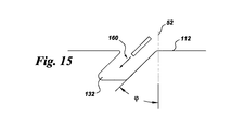
特に、図15〜図17に示すように、各々の溝132は、研磨液ジェット160の第1のパスで研磨液ジェット160を基材110の表面112に対して側角(lateral angle)で噴射し(図15)、次いで、次のパスを上記側角に対向する角度で行う(図16)ことによって形成することができ、各々の溝はその開口136で狭まってリエントラント形の溝(図16を参照して以下で説明する。)を生じる。通例、溝の所望の深さ及び幅が達成されるように複数のパスを実施する。この技術は、本願出願人に譲渡された「Components with re−entrant shaped cooling channels and methods of manufacture」と題するBunker他の米国特許出願第12/943624号に記載されており、その開示内容は援用によって本明細書の内容の一部をなす。さらに、リエントラント形の溝132を形成するステップは、追加のパスを実施することをさらに含んでいてもよく、側角とその対向角度との間の1以上の角度で研磨液ジェットを溝132の底134に噴射して溝132の底134から材料を除去する。
In particular, as shown in FIGS. 15-17, each
次に例えば図2、図5、図6及び図13を参照して、部品100は、基材100の外面112の少なくとも一部の上に設けられた皮膜150をさらに含む。例えば図13及び図14に示すように、皮膜150は少なくとも構造皮膜54を含む。皮膜150は適当な材料を含んでいて、部品に結合している。図5〜図7に例示する構成では、構造皮膜54は、1以上の溝132の上に延在して、1以上の溝132と構造皮膜54とが一緒に各フィレット94を冷却するための1以上のチャネル130を画成する。
2, 5, 6 and 13, the
ある具体的な構成では、皮膜150の厚さは0.1〜2.0mm、特に0.2〜1mmの範囲内であり、特に産業用部品では0.2〜0.5mmの範囲内である。航空機用の部品では、この範囲は通例0.1〜0.25mmである。ただし、個々の部品100に対する要件に応じて、その他の厚さを用いてもよい。
In one specific configuration, the thickness of the
皮膜150は構造皮膜層を含んでおり、任意には追加の皮膜層をさらに含んでいてもよい。皮膜層は、様々な技術を用いて成膜できる。ある具体的なプロセスでは、構造皮膜層は、イオンプラズマ堆積(カソードアーク)法を実施することによって成膜される。イオンプラズマ堆積装置及び方法の例は、本願出願人に譲渡された「Method and apparatus for cathodic arc ion plasma deposition」と題するWeaver他の米国公開特許出願第20080138529号に記載されており、その開示内容は援用によって本明細書の内容の一部をなす。簡潔に説明すると、イオンプラズマ堆積は、皮膜材料で形成された消耗カソードを真空チャンバ内の真空環境に配置し、真空環境内に基材110を設け、カソードに電流を供給してカソード面にカソードアークを形成してカソード面からの皮膜材料のアーク誘導エロージョンを生じせしめ、カソードからの皮膜材料を基材表面112に堆積させることを含む。
The
イオンプラズマ堆積を用いて成膜した皮膜の非限定的な例は、「Double−wall airfoil」と題するJackson他の米国特許第5626462号を参照して以下で詳細に説明する通り、構造皮膜、ボンドコート及び耐酸化性皮膜が挙げられる。ある種の高温ガス経路部品100では、構造皮膜はニッケル基又はコバルト基合金を含んでおり、特に超合金又は(Ni,Co)CrAlY合金を含む。例えば、基材材料がγ又はγ’相を含むNi基超合金である場合、構造皮膜は同様の組成の材料を含むものでよく、これについては、米国特許第5626462号を参照して以下で詳細に説明する。
Non-limiting examples of films deposited using ion plasma deposition include structural films, bonds, as described in detail below with reference to Jackson et al. US Pat. No. 5,626,462 entitled “Double-wall airfoil”. Examples include coats and oxidation-resistant films. In certain hot
別のプロセスでは、構造皮膜は、溶射法及びコールドスプレー法の少なくとも一方を実施することによって成膜される。例えば、溶射法には、燃焼式溶射又はプラズマ溶射があり、燃焼式溶射には、HVOF溶射(high velocity oxygen fuel spraying)又はHVAF溶射(high velocity air fuel spraying)があり、プラズマ溶射には、大気(例えば、空気又は不活性ガス)プラズマ溶射、或いは減圧プラズマ溶射(LPPS、真空プラズマ溶射(VPS)としても知られる)がある。ある非限定的な例では、(Ni,Co)CrAlY皮膜は、 HVOF又はHVAFで成膜される。構造皮膜のその他の堆積技術の例としては、特に限定されないが、スパッタリング、電子ビーム物理堆積法、化学めっき法及び電気めっき法が挙げられる。 In another process, the structural coating is deposited by performing at least one of a thermal spray method and a cold spray method. For example, the spraying method includes combustion spraying or plasma spraying, and the combustion spraying includes HVOF spraying (high velocity oxygen fuel spraying) or HVAF spraying (high velocity air fuel spraying). (E.g., air or inert gas) plasma spraying, or low pressure plasma spraying (also known as LPPS, vacuum plasma spraying (VPS)). In one non-limiting example, the (Ni, Co) CrAlY film is deposited with HVOF or HVAF. Examples of other deposition techniques for the structural coating include, but are not limited to, sputtering, electron beam physical deposition, chemical plating, and electroplating.
ある具体的な構成では、構造皮膜層及び適宜追加の皮膜相の堆積には、複数の堆積技術を使用するのが望ましい。例えば、最初の構造皮膜層をイオンプラズマ堆積法を用いて堆積し、次に堆積される層及び適宜追加の層(図示せず)を、燃焼式溶射法又はプラズマ溶射法のような別の技術を用いて堆積してもよい。使用する材料に応じて、皮膜層に異なる堆積技術を用いると、例えば、特に限定されないが、歪み耐性、強度、密着性及び/又は延性などの特性に利点が得られることがある。 In one particular configuration, it may be desirable to use multiple deposition techniques for the deposition of the structural coating layer and optionally additional coating phases. For example, the first structural coating layer is deposited using ion plasma deposition, and then the layer to be deposited and optionally additional layers (not shown) are applied to another technique such as combustion spraying or plasma spraying. You may deposit using. Depending on the material used, different deposition techniques may be used for the coating layer, for example, although not particularly limited, advantages such as strain resistance, strength, adhesion and / or ductility may be obtained.
図3に示す構成では、部品100はタービン動翼100を含んでおり、図5に示す構成では、基材110は、中空内部空間114と1以上の冷却流路130との間に延在してそれらを流体連通せしめる1以上のアクセスチャネル140をさらに画成する。各冷却流路に通じる内部アクセス穴140は、一定断面積の直線的穴、賦形穴(楕円形など)又は収束もしくは発散穴のいずれかとして穿孔することができる。アクセス穴の形成法は、本願出願人に譲渡された「Components with cooling channels and methods of manufacture」と題するRonald S.Bunker他の米国特許出願第13/210697号に記載されており、その開示内容は援用によって本明細書の内容の一部をなす。
In the configuration shown in FIG. 3, the
冷却流路130については数多くの構成が可能である。例えば図5に示す構成では、冷却流路130の少なくとも1つはフィレット94に沿って半径方向に延在している。なお、図5の断面図には、フィレットに沿って半径方向に延在する1つの冷却流路しか示していないが、複数の冷却流路が、部品の異なる断面におけるフィレットに沿って半径方向に延在していてもよい。好適には、この半径方向の構成は、皮膜の下でフィレットを冷却し、従来の冷却部品に比べて、フィレットにおける熱勾配及び熱応力を大幅に低減する。その結果、フィレットを大きくすることができ、回転部品に対する負荷要件を満足するのに役立つだけでなく、鋳造コストも下げる(フィレットが大きいと、鋳造収率又は皮膜の密着性に対する制約が減るため)。
Many configurations of the
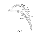
同様に、図6に例示する構成では、冷却流路130の少なくとも1つはフィレット94に沿って軸方向に延在している。なお、図6の断面図には、フィレットに沿って軸方向に延在する1つの冷却流路しか示していないが、複数の冷却流路がフィレットに沿って軸方向に延在していてもよい。好適には、この軸方向の構成は冷却をフィレット内部に集中させる。
Similarly, in the configuration illustrated in FIG. 6, at least one of the cooling
図7に例示する構成では、冷却流路130の少なくとも1つはフィレット94に沿って軸方向−半径方向に延在している。図7に示す数(2つ)の冷却流路は、例示にすぎず、1つ又は数多くの冷却流路がフィレットに沿って軸方向−半径方向に延在していてもよい。
In the configuration illustrated in FIG. 7, at least one of the cooling
図面から明らかな通り、冷却流路は幾通りかに構成できる。ある部分で特定の構成を選択し、製造の際に利点を得ることができるが、これはすべての場所で機械加工装置に均等にアクセスできるわけではないからである。1つの面を空間に固定して保持するため、装置を複雑な表面半径で横断させる必要のある軸方向−半径方向タイプの機械加工よりも、軸方向チャネル又は半径方向チャネルのいずれかの機械加工が簡単なこともある。冷却用には、翼形部は、例えば空気力学的応答のためのリブのような内部構造を有していなければならないので、冷却剤供給穴には配置に制限があり、ある部品では軸方向−半径方向のチャネルを用いる必要がある。別の例では、フィレットは寿命制限領域となることがあり、単に軸方向チャネルを設けることによって最大の利益を得ることができる。またこの点で考慮されるのはチャネルからの応力集中因子であり、チャネルを特定の配向にすることによって最小限にすることができる。 As is apparent from the drawing, the cooling channel can be constructed in several ways. A particular configuration can be selected in some parts and gained advantages in manufacturing, since the machining equipment is not equally accessible at all locations. Either axial or radial channel machining, rather than axial-radial type machining that requires the device to be traversed with complex surface radii to hold one surface fixed in space Sometimes it is easy. For cooling, the airfoil must have an internal structure such as a rib for aerodynamic response, for example, so the coolant supply holes have limited placement and in some parts axial -It is necessary to use radial channels. In another example, the fillet can be a lifetime limiting region, and maximum benefit can be obtained by simply providing an axial channel. Also considered in this regard is the stress concentration factor from the channel, which can be minimized by making the channel a specific orientation.
上述の通り、溝132は多種多様な幾何形状を取り得る。図13及び図14に示す構成では、各々の溝132は開口136を有しており、各々の溝132はその開口136で狭まっていてリエントラント形132をなし、各冷却流路130はリエントラント形の冷却流路130をなす。リエントラント形の溝は米国特許出願第12/943624号に記載されている。ある具体的な構成では、リエントラント形溝132の底面134は、その溝132の上面136よりも2倍以上幅が広い。例えば、この構成では、溝132の底面134が0.75mmのとき、上面136の幅は0.375mm未満である。さらに具体的な構成では、リエントラント形溝132の底面134はその溝132の上面136よりも3倍以上幅が広く、特にリエントラント形溝132の底面134はその溝132の上面136よりも3〜4倍幅が広い。好適には、底面と上面との比が大きいほど、マイクロチャネル130の全体的な冷却体積が増大する一方で、溝132を皮膜150で埋めずに(犠牲充填材を用いずに)溝132の上で皮膜150を成膜するのが容易になる。
As described above, the
ある具体的な構成では、構造皮膜54は各々の溝132を完全に橋架けしており、皮膜150は各マイクロチャネル130を封止する。ただし、別の構成では、構造皮膜54は1以上の透過性スロット144(例えば、皮膜内の多孔又は皮膜内の隙間)を画成し、図14に示すように、構造皮膜は1以上の溝132の各々を完全には橋架けしていない。図14では、スロット144を一様な直線的幾何形状をもつものとして図解したが、典型的には、各スロット144は不規則な幾何形状を有しており、皮膜150が施工されて厚さを増すので、スロット144の幅は変化する。最初に、皮膜150の第1の部分を基材110に施工する際、スロット144の幅はマイクロチャネル130の上面136の幅の50%程度である。皮膜150を堆積させるにつれて、スロット144は上面136の幅の5%以下まで狭まる。ある具体例では、スロット144の幅はその最も狭い点でそのマイクロチャネルの上面136の幅の5%〜20%である。さらに、スロット144は多孔質であってよく、その場合「多孔質」スロット144は接続部つまり無間隙のスポット又は位置を有する。好適には、スロット144は、皮膜150に応力緩和をもたらす。
In one specific configuration, the structural coating 54 completely bridges each
上述の通り、部品はタービン動翼を含んでいてもよい。図12に例示する構成では、基材110は、プラットフォーム92と一体につながるシャンク96をさらに画成する。図12に示す構成では、1以上の通路146がシャンク96を貫通していて、中空内部空間114とシャンク96の外部領域とを流体連通せしめている。典型的には、通路146は放電加工又は電解加工によって形成され、十分な大きさのときは鋳造の一部として形成できる。さらに、図12に示す構成では、1以上のアクセス穴148が少なくとも部分的にプラットフォーム92内に延在して、冷却流路130とシャンク96の外部領域とを流体連通せしめる。図12に示す構成では、アクセスチャネル148は冷却流路130の底面134に通じている。図12に示す構成では、冷却流路130はフィレット94に沿って半径方向に延在しており、フィレット94の上端部95に出口を有する。
As described above, the component may include a turbine blade. In the configuration illustrated in FIG. 12, the
図12に示す構成の利点は、以下のように理解することができる。シャンクポケット(シャンクとプラットフォーム下面とで画成される空間の領域)が通路146からの冷却剤で加圧され、マイクロチャネルによってもたらされる冷却に加えて、プラットフォームの下面での全般的レベルの冷却がなされる。この加圧によって高温ガスがこの領域に入り込まないようになる。これは、フィレットを貫通して翼形部に至る通路146を機械加工しない場合に、マイクロチャネルへの好適な冷却源となる。
The advantages of the configuration shown in FIG. 12 can be understood as follows. The shank pocket (the area of space defined by the shank and the platform underside) is pressurized with coolant from the
次に、上述の冷却構成の全般について述べると、表面曲率に適合したフィレットの外面に冷却流路を配置することによって、上述の冷却構成で、耐荷重能力を高めるため金属温度を低く維持しながら、フィレットの半径を増大させることができる。さらに、本発明で新たに可能となったフィレットサイズの増大によって、皮膜のミクロ組織が改善され、これらの領域でのTBC剥離のおそれを低減することができる。さらに、上述のフィレット冷却は設計面で柔軟性に富み、フィレットに冷却を事実上あらゆる配向で組み込むことができる。 Next, in general, the above cooling configuration will be described. By arranging a cooling channel on the outer surface of the fillet adapted to the surface curvature, with the above cooling configuration, the metal temperature is kept low to increase the load bearing capacity. The fillet radius can be increased. Furthermore, the increase in fillet size newly made possible by the present invention improves the microstructure of the coating and reduces the risk of TBC stripping in these areas. Furthermore, the fillet cooling described above is flexible in design, and cooling can be incorporated into the fillet in virtually any orientation.
ただし、フィレットの冷却改善によって、大きなフィレットを用いることができるようになるが、本発明は従来の大きさのフィレットにも適用できる。例えば、ある既存の部材では、フィレットのサイズを大きくする必要がなくても、マイクロ冷却流路によって残りの利点が得られる。例えば、チャネルに、翼形部の内部空洞に直接穿孔された冷却供給穴を設けて、低温の基材材料は表面にマイクロチャネルを貫入させることができる。 However, although the fillet cooling can be improved by using a large fillet, the present invention can be applied to a fillet having a conventional size. For example, in some existing members, the microcooling channel provides the remaining benefits without having to increase the fillet size. For example, the channel can be provided with cooling supply holes drilled directly into the airfoil internal cavity, allowing the cold substrate material to penetrate the microchannel into the surface.
図2〜図4、図8〜図11、図13、図14を参照して、部品100の別の構成について説明する。例えば図2及び図4に示すように、部品100は、外面112と内面116とを有する基材110を含む。例えば図2及び図4に示すように、内面116は1以上の中空内部空間114を画成する。例えば図2及び図3に示すように、基材110の外面112は、正圧側壁24と負圧側壁26とを画成しており、正圧側壁24と負圧側壁26は、部品100の前縁28及び後縁30で一体となって部品の翼形部90部を形成している。図2及び図3に示すように、負圧側26は凸面であり、正圧側24は凹面である。例えば図3及び図4に示すように、基材110の外面112は、1以上のプラットフォーム92と、翼形部90と各プラットフォーム92との間に延在してそれらを一体につなぐ1以上のフィレット94とをさらに画成する。
Another configuration of the
例えば図8及び図9に示すように、外面112は、少なくとも部分的に各プラットフォーム92に沿って延在する1以上の溝132を画成している。例えば図8及び図9に示すように、各々の溝132は中空内部空間114と流体連通している。
For example, as shown in FIGS. 8 and 9, the
例えば図2、図8及び図13に示すように、部品100は、基材110の外面112の少なくとも一部の上に設けられた皮膜150をさらに含む。皮膜150は少なくとも構造皮膜54を含んでおり、上述の通りである。例えば図8に示すように、構造皮膜54は、溝132の上に延在して、溝132と構造皮膜54とが一緒にプラットフォーム94を冷却するための1以上のチャネル130を画成する。好適には、上述の冷却構成によって、プラットフォームの冷却を促進することができ、これは、中子プラットフォームの必要性をなくすのに役立ち、部品の予想コストを下げる。
For example, as shown in FIGS. 2, 8 and 13, the
図3に示す構成では、部品100はタービン動翼100を含んでおり、図9に示す構成では、基材110は、中空内部空間114と1以上の冷却流路130との間に延在してそれらを流体連通せしめる1以上のアクセスチャネル140をさらに画成する。アクセスチャネル140については上述した。
In the configuration shown in FIG. 3, the
冷却流路130については数多くの構成が可能である。例えば図8に示す構成では、冷却流路130の少なくとも1つはプラットフォーム92に沿って軸方向及び/又は長手方向に延在している。すなわち、冷却流路130は、プラットフォームに沿って軸方向、長手方向又は軸方向と長手方向の両方に延在し得る。好適には、この構成はプラットフォーム92の冷却を促進する。図8に示す構成では、冷却流路130は、プラットフォーム端部98の近傍に出口を有する。ただし、別の構成では、冷却流路130は、プラットフォーム92の端部98に出口を有する。後者の構成は明示されていない。ただし、プラットフォーム端部98は図8に示してある。
Many configurations of the
図9に例示する構成では、冷却流路130の少なくとも1つはフィレット94に沿って半径方向に延在し、次いでプラットフォーム92に沿って軸方向及び/又は長手方向に延在する。好適には、この構成はフィレット94及びプラットフォーム92の冷却を促進する。図9に示す構成では、冷却流路130は、プラットフォーム端部98の近傍に出口を有する。ただし、別の構成では、冷却流路130はプラットフォーム92の端部98に出口を有する。この後者の構成は明示されていない。ただし、プラットフォーム端部98は図9に示してある。
In the configuration illustrated in FIG. 9, at least one of the cooling
上述の通り、部品100はタービン動翼を含んでいてもよい。図10に例示する構成では、基材110は、プラットフォーム92と一体につながるシャンク96をさらに画成する。図10に示す構成では、1以上の通路146がシャンク96を貫通していて、中空内部空間114とシャンク96の外部領域とを流体連通せしめている。上述の通り、典型的には、通路146は放電加工又は電解加工によって形成されるが、十分な大きさのときは鋳造の一部として形成できる。さらに、図10に示す構成では、1以上のアクセス穴148が少なくとも部分的にプラットフォーム92内に延在して、冷却流路130とシャンク96の外部領域とを流体連通せしめる。図10に示す構成では、アクセスチャネル148は冷却流路130の底面134に通じている。図10に示す構成では、冷却流路130はプラットフォーム92に沿って軸方向及び/又は長手方向に延在しており、プラットフォーム端部98の近傍に出口を有する。ただし、冷却流路130がプラットフォーム端部98に出口を有していてもよい。この後者の構成は明示されていない。ただし、プラットフォーム端部98は図10に示してある。好適には、マイクロチャネルをプラットフォーム内に配置することによって、図10に示す構成では、冷却剤が高温ガス経路に近づいて改善された冷却が得られる。この構成は、プラットフォーム内部に冷却通路又は空洞を鋳造する必要性を低減又は完全になくすことができる。また、シャンク−プラットフォーム空洞内の冷却剤への熱流束の量が低減し、マイクロチャネルに供給される前の流体が単に加圧機能を果たせるようになる。
As described above, the
図11を参照して、別のタービン動翼100の構成について説明する。図11に示す構成では、基材110は、プラットフォーム92と一体につながるシャンク96と、少なくとも部分的にシャンク96内に延在して中空内部空間114と各冷却流路130とを流体連通せしめる1以上のアクセス穴140とをさらに画成しており、図11に示す構成では、冷却流路はプラットフォーム92に沿って軸方向及び/又は長手方向に延在し、プラットフォーム端部98の近傍に出口を有する。ただし、冷却流路130はプラットフォーム端部98に出口を有していてもよい。この後者の構成は明示されていない。ただし、プラットフォーム端部98は図10に示してある。好適には、図11に示す冷却構成はプラットフォーム92の冷却を促進し、これは、中子プラットフォームの必要性をなくすのに役立ち、部品の予想コストを下げる。
With reference to FIG. 11, the configuration of another
図13及び図14を参照して上記で説明した通り、ある具体的な構成では、溝132及び冷却流路130はリエントラント形とし得る。同様に、図14を参照して上記で説明した通り、ある具体的な構成では、構造皮膜54は1以上の透過性スロット144を画成し、構造皮膜は溝132を完全には橋架けしていない。ただし、他の構成では、構造皮膜54は溝132を封止している。
As described above with reference to FIGS. 13 and 14, in some specific configurations, the
上述の通り、上述の冷却式プラットフォーム構成の利点として、中子プラットフォームの必要性をなくすのに役立ち、部品の予想コストを下げることが挙げられる。 As mentioned above, the advantages of the cooled platform configuration described above can help eliminate the need for a core platform and reduce the expected cost of the parts.
図2〜図17を参照して、部品100内に冷却流路130を形成する方法について説明する。図2〜図4を参照して上記で説明した通り、部品100は外面112と内面116とを有する基材110を含んでおり、内面116は1以上の中空内部空間114を画成し、基材110の外面112は正圧側壁24と負圧側壁26とを画成する。正圧側壁24と負圧側壁26は部品100の前縁28及び後縁30で一体につながっている。図2及び図3に示すように、負圧側26は凸面であり、正圧側24は凹面である。例えば図3及び図4に示すように、基材110の外面112は、1以上のプラットフォーム92と、翼形部90と各プラットフォーム92との間に延在してそれらを一体につなぐ1以上のフィレット94とをさらに画成する。
A method of forming the
図5及び図8〜図12に示すように、本方法は、基材110の外面112に1以上の溝を形成するステップであって、少なくとも部分的にフィレット94に沿って或いは少なくとも部分的にプラットフォーム92に沿って延在する溝を形成するステップを含む。典型的には、上述の通り、本方法は、基材110の外面112に溝132を形成する前に基材110を鋳造するステップをさらに含んでいる。
As shown in FIGS. 5 and 8-12, the method includes forming one or more grooves in the
図2、図5、図13及び図14に示すように、本方法はさらに、基材110の外面112の少なくとも一部の上に皮膜150を成膜するステップを含む。皮膜150及びその成膜のための堆積技術の例については上述した。ある具体的プロセスでは、基材110の外面112の少なくとも一部の上に皮膜150を成膜するステップはイオンプラズマ堆積法を実施することを含む。ある具体的な構成では、皮膜150は超合金を含む。ある具体的プロセスでは、基材110の外面112の少なくとも一部の上に皮膜150を成膜するステップは溶射法を実施することを含む。溶射法の例としては、HVOF溶射及びHVAF溶射が挙げられる。ある具体的プロセスでは、基材110の外面112の少なくとも一部の上に皮膜150を成膜するステップは、減圧プラズマ溶射(LPPS)法を実施することを含む。上記で説明した通り、皮膜150は、溝132の上に延在する1以上の構造皮膜54を含んでいて、溝132と構造皮膜54とが一緒に部品100のフィレット94及びプラットフォーム92の少なくとも一方を冷却するための1以上のチャネル130を画成する。
As shown in FIGS. 2, 5, 13 and 14, the method further includes depositing a
図5、図6、図11及び図13に示すように、本方法は、適宜、基材110に1以上のアクセス穴140を形成するステップであって、溝132を中空内部空間114と流体連通させるアクセス穴140を形成するステップをさらに含んでいてもよい。上述の通り、アクセス穴を形成するための技術は、本願出願人に譲渡されたRonald S.Bunker他の米国特許出願第13/210697号に記載されている。例えば、アクセス穴は、研磨液ジェット加工によって形成できる。さらに、内部アクセス穴140は、一定断面積の直線的穴、賦形穴(楕円形など)又は収束もしくは発散穴のいずれかとして穿孔することができる。
As shown in FIGS. 5, 6, 11, and 13, the method optionally includes forming one or
上記で説明した通り、ある具体的な構成では、溝はリエントラント形である。ある具体的プロセスでは、リエントラント形溝132は、Bunker他の米国特許出願第12/943624号に記載のように、例えば図15〜図17に示すように、基材110の表面112に研磨液ジェット160を噴射することによって形成できる。例えば、リエントラント形の溝132は、研磨液ジェット160の第1のパスで、基材110の表面112に対して側角に研磨液ジェット160を噴射し(図15)、側角と対向する角度で次のパスを行うこと(図16)によって形成し得る。ある具体的なプロセスでは、リエントラント形溝132を形成するステップは、1以上の追加のパスを実施するステップをさらに含んでおり(図17)、側角とその対向角度との間の1以上の角度で研磨液ジェット160を溝132の底面134に噴射して、溝132の底面134から材料を除去する。さらに一般的には、リエントラント形溝132は、研磨液ジェット、プランジ電解加工(ECM)、放電加工(EDM)、回転電極による放電加工(EDM)(ミリングEDM)及びレーザ機械加工の1以上を用いて形成することができる。
As explained above, in one particular configuration, the grooves are reentrant. In one specific process, the
上述の通り、フィレット及び/又はプラットフォームの冷却にマイクロチャネルを用いると、従来の鋳造冷却通路に比して顕著な利点が得られる。特に、表面曲率に適合したフィレットの外面に冷却流路を配置することによって、上述の冷却構成で、耐荷重能力を高めるため金属温度を低く維持しながら、フィレットの半径を増大させることができる。
さらに、フィレットが大きいと、鋳造収率に対する制約が減るので、鋳造コストが下がる。さらに、本発明で新たに可能となったフィレットサイズの増大によって、フィレット領域(一般に溶射プロセスの際のミクロ組織制御が難しい領域である。)でのセラミック皮膜のミクロ組織も改善される。さらに、上述のフィレット及び/又はプラットフォーム冷却は設計面で柔軟性に富み、フィレット/プラットフォームに冷却を事実上あらゆる配向で組み込むことができる。加えて、フィレット輪郭が大きくなることで、空力効率も向上すると予測される。
As described above, the use of microchannels for cooling fillets and / or platforms provides significant advantages over conventional cast cooling passages. In particular, by arranging the cooling flow path on the outer surface of the fillet adapted to the surface curvature, the fillet radius can be increased while maintaining the metal temperature low in order to increase the load bearing capacity in the above-described cooling configuration.
Furthermore, a large fillet reduces casting costs because constraints on casting yield are reduced. Furthermore, the increase in fillet size newly made possible by the present invention also improves the microstructure of the ceramic coating in the fillet region (generally a region where it is difficult to control the microstructure during the thermal spraying process). Furthermore, the fillet and / or platform cooling described above is flexible in design, and cooling can be incorporated into the fillet / platform in virtually any orientation. In addition, the aerodynamic efficiency is also expected to be improved by increasing the fillet contour.
本発明の幾つかの特徴だけについて例示・説明してきたが、数多くの修正及び変更が当業者には自明であろう。従って、特許請求の範囲は、このような本発明の技術的思想に属する修正及び変更を包含する。 While only certain features of the invention have been illustrated and described, many modifications and changes will be apparent to those skilled in the art. Therefore, the scope of the claims includes such modifications and changes belonging to the technical idea of the present invention.
10 ガスタービンエンジン
12 圧縮機
14 燃焼器
16 タービン
18 シャフト
20 燃料ノズル
24 基材(部品)の正圧側壁
26 基材(部品)の負圧側壁
28 部品の前縁
30 部品の後縁
32 冷却流路の入口部
34 冷却流路の中間部
36 冷却流路の出口部
52 表面法線
54 構造皮膜
90 翼形部
92 プラットフォーム
94 フィレット
96 シャンク
98 プラットフォーム端部
100 高温ガス経路部品
110 基材
112 基材の外面
114 中空内部空間
116 基材の内面
130 チャネル
132 溝
134 溝の底面
136 溝の開口(上面)
140 アクセス穴
144 透過性スロット
146 シャンクを貫通する通路
148 プラットフォームを貫通するアクセス穴
150 皮膜
160 研磨液ジェット
DESCRIPTION OF
140
Claims (13)
基材の外面の少なくとも一部の上に設けられた皮膜であって、皮膜が少なくとも構造皮膜を含んでいて、構造皮膜が1以上の溝の上に延在していて、1以上の溝と構造皮膜とが一緒に各フィレット又は各プラットフォームを冷却するための1以上のチャネルを画成している、皮膜と
を備える部品。 A base material including an outer surface and an inner surface, wherein the inner surface defines one or more hollow internal spaces, and the outer surface of the base material defines a pressure side wall and a suction side wall, The suction side wall is united at the leading and trailing edges of the part to form the airfoil of the part, and the outer surface of the substrate further includes one or more platforms and an airfoil extending radially outward from the platform. defining one or more grooves and defines the one or more fillets connecting them extends integrally, the outer surface, extends over one or more fillets between each platform Each of the one or more grooves has a length and a bottom surface extending at least partially along the surface of the substrate, and each groove is in fluid communication with each hollow interior space. Material,
A coating provided on at least a portion of the outer surface of the substrate, the coating including at least a structural coating, the structural coating extending over the one or more grooves, and the one or more grooves; A component comprising a coating, which together with the structural coating define one or more channels for cooling each fillet or each platform.
プラットフォームと一体につながるシャンクと、
シャンクを貫通して各中空内部空間とシャンクの外部領域とを流体連通せしめる1以上の通路と、
少なくとも部分的にプラットフォーム内に延在して冷却流路とシャンクの外部領域とを流体連通せしめる1以上のアクセス穴であって、各冷却流路の底面に通じる1以上のアクセス穴と
を画成している、請求項1乃至5のいずれかに記載の部品。 The component includes turbine blades, and the substrate further comprises:
A shank connected to the platform,
One or more passages that pass through the shank and provide fluid communication between each hollow interior space and the outer region of the shank;
One or more access holes that extend at least partially into the platform and provide fluid communication between the cooling flow path and the outer region of the shank, and define one or more access holes that communicate with the bottom surface of each cooling flow path The component according to any one of claims 1 to 5 .
プラットフォームと一体につながるシャンクと、
少なくとも部分的にプラットフォーム内に延在して各中空内部空間と各冷却流路とを流体連通せしめる1以上のアクセス穴と
を画成しており、冷却流路が、各プラットフォームに沿って正圧側壁から負圧側壁に向かう方向、前縁から後縁に向かう方向又は正圧側壁から負圧側壁に向かう方向と前縁から後縁に向かう方向の両方向に延在する、請求項1乃至12のいずれかに記載の部品。
The component includes turbine blades, and the substrate further comprises:
A shank connected to the platform,
One or more access holes extending at least partially within the platform to fluidly communicate each hollow interior space and each cooling channel, wherein the cooling channel is positive pressure along each platform. 13. The direction of the side wall toward the suction side wall, the direction from the front edge toward the rear edge, or the direction from the pressure side wall toward the suction side wall and the direction toward the rear edge from the front edge to the rear edge . Any of the parts.
Applications Claiming Priority (2)
| Application Number | Priority Date | Filing Date | Title |
|---|---|---|---|
| US13/478,517 | 2012-05-23 | ||
| US13/478,517 US9243503B2 (en) | 2012-05-23 | 2012-05-23 | Components with microchannel cooled platforms and fillets and methods of manufacture |
Publications (3)
| Publication Number | Publication Date |
|---|---|
| JP2013245673A JP2013245673A (en) | 2013-12-09 |
| JP2013245673A5 JP2013245673A5 (en) | 2016-07-07 |
| JP6192982B2 true JP6192982B2 (en) | 2017-09-06 |
Family
ID=48538962
Family Applications (1)
| Application Number | Title | Priority Date | Filing Date |
|---|---|---|---|
| JP2013105698A Active JP6192982B2 (en) | 2012-05-23 | 2013-05-20 | MICROCHANNEL COOLING PLATFORM, PARTS HAVING FILLET AND MANUFACTURING METHOD |
Country Status (4)
| Country | Link |
|---|---|
| US (1) | US9243503B2 (en) |
| EP (1) | EP2666965B1 (en) |
| JP (1) | JP6192982B2 (en) |
| RU (1) | RU2013123029A (en) |
Families Citing this family (13)
| Publication number | Priority date | Publication date | Assignee | Title |
|---|---|---|---|---|
| US8387245B2 (en) * | 2010-11-10 | 2013-03-05 | General Electric Company | Components with re-entrant shaped cooling channels and methods of manufacture |
| US8673397B2 (en) | 2010-11-10 | 2014-03-18 | General Electric Company | Methods of fabricating and coating a component |
| DE102013109116A1 (en) | 2012-08-27 | 2014-03-27 | General Electric Company (N.D.Ges.D. Staates New York) | Component with cooling channels and method of manufacture |
| US9238265B2 (en) | 2012-09-27 | 2016-01-19 | General Electric Company | Backstrike protection during machining of cooling features |
| US9156114B2 (en) | 2012-11-13 | 2015-10-13 | General Electric Company | Method for manufacturing turbine nozzle having non-linear cooling conduit |
| US9200534B2 (en) * | 2012-11-13 | 2015-12-01 | General Electric Company | Turbine nozzle having non-linear cooling conduit |
| US10612392B2 (en) * | 2014-12-18 | 2020-04-07 | United Technologies Corporation | Gas turbine engine component with conformal fillet cooling path |
| US10344597B2 (en) | 2015-08-17 | 2019-07-09 | United Technologies Corporation | Cupped contour for gas turbine engine blade assembly |
| US10227876B2 (en) | 2015-12-07 | 2019-03-12 | General Electric Company | Fillet optimization for turbine airfoil |
| US10267161B2 (en) * | 2015-12-07 | 2019-04-23 | General Electric Company | Gas turbine engine with fillet film holes |
| US10247009B2 (en) * | 2016-05-24 | 2019-04-02 | General Electric Company | Cooling passage for gas turbine system rotor blade |
| KR102000836B1 (en) * | 2017-09-27 | 2019-07-16 | 두산중공업 주식회사 | Gas Turbine |
| US20220205364A1 (en) * | 2020-12-30 | 2022-06-30 | General Electric Company | Cooling circuit having a bypass conduit for a turbomachine component |
Family Cites Families (74)
| Publication number | Priority date | Publication date | Assignee | Title |
|---|---|---|---|---|
| US4487550A (en) | 1983-01-27 | 1984-12-11 | The United States Of America As Represented By The Secretary Of The Air Force | Cooled turbine blade tip closure |
| US4893987A (en) | 1987-12-08 | 1990-01-16 | General Electric Company | Diffusion-cooled blade tip cap |
| US5660523A (en) | 1992-02-03 | 1997-08-26 | General Electric Company | Turbine blade squealer tip peripheral end wall with cooling passage arrangement |
| US5382135A (en) * | 1992-11-24 | 1995-01-17 | United Technologies Corporation | Rotor blade with cooled integral platform |
| US5340278A (en) * | 1992-11-24 | 1994-08-23 | United Technologies Corporation | Rotor blade with integral platform and a fillet cooling passage |
| JP3137527B2 (en) | 1994-04-21 | 2001-02-26 | 三菱重工業株式会社 | Gas turbine blade tip cooling system |
| US5626462A (en) | 1995-01-03 | 1997-05-06 | General Electric Company | Double-wall airfoil |
| US5640767A (en) | 1995-01-03 | 1997-06-24 | Gen Electric | Method for making a double-wall airfoil |
| US6383602B1 (en) | 1996-12-23 | 2002-05-07 | General Electric Company | Method for improving the cooling effectiveness of a gaseous coolant stream which flows through a substrate, and related articles of manufacture |
| US5875549A (en) * | 1997-03-17 | 1999-03-02 | Siemens Westinghouse Power Corporation | Method of forming internal passages within articles and articles formed by same |
| DE19737845C2 (en) * | 1997-08-29 | 1999-12-02 | Siemens Ag | Method for producing a gas turbine blade, and gas turbine blade produced using the method |
| US6321449B2 (en) | 1998-11-12 | 2001-11-27 | General Electric Company | Method of forming hollow channels within a component |
| US6214248B1 (en) | 1998-11-12 | 2001-04-10 | General Electric Company | Method of forming hollow channels within a component |
| US6190129B1 (en) | 1998-12-21 | 2001-02-20 | General Electric Company | Tapered tip-rib turbine blade |
| US6086328A (en) | 1998-12-21 | 2000-07-11 | General Electric Company | Tapered tip turbine blade |
| US6059530A (en) | 1998-12-21 | 2000-05-09 | General Electric Company | Twin rib turbine blade |
| US6231307B1 (en) | 1999-06-01 | 2001-05-15 | General Electric Company | Impingement cooled airfoil tip |
| DE59909337D1 (en) | 1999-06-03 | 2004-06-03 | Alstom Technology Ltd Baden | Process for the production or repair of cooling channels in single-crystalline components of gas turbines |
| US6164914A (en) | 1999-08-23 | 2000-12-26 | General Electric Company | Cool tip blade |
| ATE483098T1 (en) * | 1999-09-24 | 2010-10-15 | Gen Electric | GAS TURBINE BLADE WITH IMPACT-COOLED PLATFORM |
| US6234755B1 (en) | 1999-10-04 | 2001-05-22 | General Electric Company | Method for improving the cooling effectiveness of a gaseous coolant stream, and related articles of manufacture |
| DE10024302A1 (en) | 2000-05-17 | 2001-11-22 | Alstom Power Nv | Process for producing a thermally stressed casting |
| US6368060B1 (en) | 2000-05-23 | 2002-04-09 | General Electric Company | Shaped cooling hole for an airfoil |
| US6341939B1 (en) * | 2000-07-31 | 2002-01-29 | General Electric Company | Tandem cooling turbine blade |
| US6617003B1 (en) | 2000-11-06 | 2003-09-09 | General Electric Company | Directly cooled thermal barrier coating system |
| US6427327B1 (en) | 2000-11-29 | 2002-08-06 | General Electric Company | Method of modifying cooled turbine components |
| US6551061B2 (en) * | 2001-03-27 | 2003-04-22 | General Electric Company | Process for forming micro cooling channels inside a thermal barrier coating system without masking material |
| US6461108B1 (en) | 2001-03-27 | 2002-10-08 | General Electric Company | Cooled thermal barrier coating on a turbine blade tip |
| US6461107B1 (en) | 2001-03-27 | 2002-10-08 | General Electric Company | Turbine blade tip having thermal barrier coating-formed micro cooling channels |
| US6494678B1 (en) | 2001-05-31 | 2002-12-17 | General Electric Company | Film cooled blade tip |
| US6602052B2 (en) | 2001-06-20 | 2003-08-05 | Alstom (Switzerland) Ltd | Airfoil tip squealer cooling construction |
| US6602053B2 (en) | 2001-08-02 | 2003-08-05 | Siemens Westinghouse Power Corporation | Cooling structure and method of manufacturing the same |
| EP1295969A1 (en) | 2001-09-22 | 2003-03-26 | ALSTOM (Switzerland) Ltd | Method of growing a MCrAIY-coating and an article coated with the MCrAIY-coating |
| EP1295970A1 (en) | 2001-09-22 | 2003-03-26 | ALSTOM (Switzerland) Ltd | MCrAlY type alloy coating |
| US6634860B2 (en) | 2001-12-20 | 2003-10-21 | General Electric Company | Foil formed structure for turbine airfoil tip |
| US6921014B2 (en) | 2002-05-07 | 2005-07-26 | General Electric Company | Method for forming a channel on the surface of a metal substrate |
| EP1387040B1 (en) | 2002-08-02 | 2006-12-06 | ALSTOM Technology Ltd | Method of protecting partial areas of a component |
| US6758651B2 (en) | 2002-10-16 | 2004-07-06 | Mitsubishi Heavy Industries, Ltd. | Gas turbine |
| US6994514B2 (en) | 2002-11-20 | 2006-02-07 | Mitsubishi Heavy Industries, Ltd. | Turbine blade and gas turbine |
| US7216428B2 (en) | 2003-03-03 | 2007-05-15 | United Technologies Corporation | Method for turbine element repairing |
| US7351290B2 (en) | 2003-07-17 | 2008-04-01 | General Electric Company | Robotic pen |
| US6905302B2 (en) | 2003-09-17 | 2005-06-14 | General Electric Company | Network cooled coated wall |
| US7600972B2 (en) | 2003-10-31 | 2009-10-13 | General Electric Company | Methods and apparatus for cooling gas turbine engine rotor assemblies |
| EP1557535A1 (en) | 2004-01-20 | 2005-07-27 | Siemens Aktiengesellschaft | Turbine blade and gas turbine with such a turbine blade |
| US7186167B2 (en) | 2004-04-15 | 2007-03-06 | United Technologies Corporation | Suspended abrasive waterjet hole drilling system and method |
| US7302990B2 (en) | 2004-05-06 | 2007-12-04 | General Electric Company | Method of forming concavities in the surface of a metal component, and related processes and articles |
| US7131817B2 (en) * | 2004-07-30 | 2006-11-07 | General Electric Company | Method and apparatus for cooling gas turbine engine rotor blades |
| ATE513980T1 (en) | 2004-12-24 | 2011-07-15 | Alstom Technology Ltd | METHOD FOR PRODUCING A COMPONENT WITH AN EMBEDDED CHANNEL AND COMPONENT |
| US7334991B2 (en) | 2005-01-07 | 2008-02-26 | Siemens Power Generation, Inc. | Turbine blade tip cooling system |
| US7249934B2 (en) | 2005-08-31 | 2007-07-31 | General Electric Company | Pattern cooled turbine airfoil |
| US7309212B2 (en) * | 2005-11-21 | 2007-12-18 | General Electric Company | Gas turbine bucket with cooled platform leading edge and method of cooling platform leading edge |
| US20090074576A1 (en) * | 2006-04-20 | 2009-03-19 | Florida Turbine Technologies, Inc. | Turbine blade with cooling breakout passages |
| US7597536B1 (en) * | 2006-06-14 | 2009-10-06 | Florida Turbine Technologies, Inc. | Turbine airfoil with de-coupled platform |
| US7625180B1 (en) * | 2006-11-16 | 2009-12-01 | Florida Turbine Technologies, Inc. | Turbine blade with near-wall multi-metering and diffusion cooling circuit |
| US7879203B2 (en) | 2006-12-11 | 2011-02-01 | General Electric Company | Method and apparatus for cathodic arc ion plasma deposition |
| US7927073B2 (en) * | 2007-01-04 | 2011-04-19 | Siemens Energy, Inc. | Advanced cooling method for combustion turbine airfoil fillets |
| US7766617B1 (en) | 2007-03-06 | 2010-08-03 | Florida Turbine Technologies, Inc. | Transpiration cooled turbine airfoil |
| US7775768B2 (en) | 2007-03-06 | 2010-08-17 | United Technologies Corporation | Turbine component with axially spaced radially flowing microcircuit cooling channels |
| US7905706B1 (en) * | 2007-12-21 | 2011-03-15 | Florida Turbine Technologies, Inc. | Turbine blade with spar and shell cooling |
| US8057178B2 (en) * | 2008-09-04 | 2011-11-15 | General Electric Company | Turbine bucket for a turbomachine and method of reducing bow wave effects at a turbine bucket |
| US8192831B2 (en) * | 2008-12-10 | 2012-06-05 | General Electric Company | Articles for high temperature service and methods for their manufacture |
| US8147196B2 (en) | 2009-05-05 | 2012-04-03 | Siemens Energy, Inc. | Turbine airfoil with a compliant outer wall |
| US8857055B2 (en) | 2010-01-29 | 2014-10-14 | General Electric Company | Process and system for forming shaped air holes |
| US8668454B2 (en) * | 2010-03-03 | 2014-03-11 | Siemens Energy, Inc. | Turbine airfoil fillet cooling system |
| US9630277B2 (en) * | 2010-03-15 | 2017-04-25 | Siemens Energy, Inc. | Airfoil having built-up surface with embedded cooling passage |
| US8905713B2 (en) | 2010-05-28 | 2014-12-09 | General Electric Company | Articles which include chevron film cooling holes, and related processes |
| US8632297B2 (en) | 2010-09-29 | 2014-01-21 | General Electric Company | Turbine airfoil and method for cooling a turbine airfoil |
| GB201016423D0 (en) | 2010-09-30 | 2010-11-17 | Rolls Royce Plc | Cooled rotor blade |
| US20120107135A1 (en) * | 2010-10-29 | 2012-05-03 | General Electric Company | Apparatus, systems and methods for cooling the platform region of turbine rotor blades |
| US8673397B2 (en) * | 2010-11-10 | 2014-03-18 | General Electric Company | Methods of fabricating and coating a component |
| US8387245B2 (en) | 2010-11-10 | 2013-03-05 | General Electric Company | Components with re-entrant shaped cooling channels and methods of manufacture |
| US8739404B2 (en) * | 2010-11-23 | 2014-06-03 | General Electric Company | Turbine components with cooling features and methods of manufacturing the same |
| US8753071B2 (en) * | 2010-12-22 | 2014-06-17 | General Electric Company | Cooling channel systems for high-temperature components covered by coatings, and related processes |
| US9206696B2 (en) | 2011-08-16 | 2015-12-08 | General Electric Company | Components with cooling channels and methods of manufacture |
-
2012
- 2012-05-23 US US13/478,517 patent/US9243503B2/en active Active
-
2013
- 2013-05-20 JP JP2013105698A patent/JP6192982B2/en active Active
- 2013-05-21 EP EP13168633.9A patent/EP2666965B1/en active Active
- 2013-05-21 RU RU2013123029/06A patent/RU2013123029A/en not_active Application Discontinuation
Also Published As
| Publication number | Publication date |
|---|---|
| JP2013245673A (en) | 2013-12-09 |
| US9243503B2 (en) | 2016-01-26 |
| CN103422907A (en) | 2013-12-04 |
| US20130312941A1 (en) | 2013-11-28 |
| RU2013123029A (en) | 2014-11-27 |
| EP2666965A1 (en) | 2013-11-27 |
| EP2666965B1 (en) | 2015-07-08 |
Similar Documents
| Publication | Publication Date | Title |
|---|---|---|
| JP6192982B2 (en) | MICROCHANNEL COOLING PLATFORM, PARTS HAVING FILLET AND MANUFACTURING METHOD | |
| US9598963B2 (en) | Components with microchannel cooling | |
| JP6259181B2 (en) | Components with microchannel cooling | |
| US10822956B2 (en) | Components with cooling channels and methods of manufacture | |
| US8739404B2 (en) | Turbine components with cooling features and methods of manufacturing the same | |
| JP6537162B2 (en) | Part with multi-layer cooling features and method of manufacture | |
| US9003657B2 (en) | Components with porous metal cooling and methods of manufacture | |
| JP5997438B2 (en) | Component with cooling channel and manufacturing method | |
| JP5941266B2 (en) | COMPONENT COMPRISING DUCTION-shaped COOLING CHANNEL AND METHOD | |
| JP5916079B2 (en) | Method for manufacturing a component using a two-layer coating | |
| US9216491B2 (en) | Components with cooling channels and methods of manufacture | |
| US20130101761A1 (en) | Components with laser cladding and methods of manufacture | |
| US9249491B2 (en) | Components with re-entrant shaped cooling channels and methods of manufacture | |
| US9327384B2 (en) | Components with cooling channels and methods of manufacture | |
| US20130078418A1 (en) | Components with cooling channels and methods of manufacture | |
| EP2728118A2 (en) | Components with asymmetric cooling channels and methods of manufacture |
Legal Events
| Date | Code | Title | Description |
|---|---|---|---|
| A521 | Request for written amendment filed |
Free format text: JAPANESE INTERMEDIATE CODE: A523 Effective date: 20160518 |
|
| A621 | Written request for application examination |
Free format text: JAPANESE INTERMEDIATE CODE: A621 Effective date: 20160518 |
|
| A977 | Report on retrieval |
Free format text: JAPANESE INTERMEDIATE CODE: A971007 Effective date: 20170328 |
|
| A131 | Notification of reasons for refusal |
Free format text: JAPANESE INTERMEDIATE CODE: A131 Effective date: 20170404 |
|
| A521 | Request for written amendment filed |
Free format text: JAPANESE INTERMEDIATE CODE: A523 Effective date: 20170620 |
|
| TRDD | Decision of grant or rejection written | ||
| A01 | Written decision to grant a patent or to grant a registration (utility model) |
Free format text: JAPANESE INTERMEDIATE CODE: A01 Effective date: 20170718 |
|
| A61 | First payment of annual fees (during grant procedure) |
Free format text: JAPANESE INTERMEDIATE CODE: A61 Effective date: 20170809 |
|
| R150 | Certificate of patent or registration of utility model |
Ref document number: 6192982 Country of ref document: JP Free format text: JAPANESE INTERMEDIATE CODE: R150 |
|
| R250 | Receipt of annual fees |
Free format text: JAPANESE INTERMEDIATE CODE: R250 |
|
| R250 | Receipt of annual fees |
Free format text: JAPANESE INTERMEDIATE CODE: R250 |
|
| R250 | Receipt of annual fees |
Free format text: JAPANESE INTERMEDIATE CODE: R250 |
|
| R250 | Receipt of annual fees |
Free format text: JAPANESE INTERMEDIATE CODE: R250 |
|
| S111 | Request for change of ownership or part of ownership |
Free format text: JAPANESE INTERMEDIATE CODE: R313113 |
|
| R350 | Written notification of registration of transfer |
Free format text: JAPANESE INTERMEDIATE CODE: R350 |