JP6188501B2 - Optical scanning apparatus and image forming apparatus - Google Patents
Optical scanning apparatus and image forming apparatus Download PDFInfo
- Publication number
- JP6188501B2 JP6188501B2 JP2013185207A JP2013185207A JP6188501B2 JP 6188501 B2 JP6188501 B2 JP 6188501B2 JP 2013185207 A JP2013185207 A JP 2013185207A JP 2013185207 A JP2013185207 A JP 2013185207A JP 6188501 B2 JP6188501 B2 JP 6188501B2
- Authority
- JP
- Japan
- Prior art keywords
- cover
- shutter
- optical
- scanning device
- optical scanning
- Prior art date
- Legal status (The legal status is an assumption and is not a legal conclusion. Google has not performed a legal analysis and makes no representation as to the accuracy of the status listed.)
- Active
Links
- 230000003287 optical effect Effects 0.000 title claims description 118
- 238000002347 injection Methods 0.000 claims description 16
- 239000007924 injection Substances 0.000 claims description 16
- 239000012778 molding material Substances 0.000 claims description 7
- 238000000465 moulding Methods 0.000 claims description 6
- 230000005484 gravity Effects 0.000 claims description 4
- 108091008695 photoreceptors Proteins 0.000 claims description 3
- 238000012546 transfer Methods 0.000 description 36
- 238000000034 method Methods 0.000 description 17
- 239000012943 hotmelt Substances 0.000 description 15
- 230000007246 mechanism Effects 0.000 description 14
- 238000004140 cleaning Methods 0.000 description 10
- 238000012423 maintenance Methods 0.000 description 6
- 238000010586 diagram Methods 0.000 description 5
- 238000007789 sealing Methods 0.000 description 5
- 238000001746 injection moulding Methods 0.000 description 4
- 239000003086 colorant Substances 0.000 description 3
- 239000000463 material Substances 0.000 description 3
- 230000002093 peripheral effect Effects 0.000 description 3
- 238000003825 pressing Methods 0.000 description 3
- 230000015572 biosynthetic process Effects 0.000 description 2
- 230000007547 defect Effects 0.000 description 2
- 230000002452 interceptive effect Effects 0.000 description 2
- 229920000098 polyolefin Polymers 0.000 description 2
- 238000011084 recovery Methods 0.000 description 2
- 239000004831 Hot glue Substances 0.000 description 1
- 210000000078 claw Anatomy 0.000 description 1
- 230000007423 decrease Effects 0.000 description 1
- 239000000428 dust Substances 0.000 description 1
- 229920001971 elastomer Polymers 0.000 description 1
- 239000000806 elastomer Substances 0.000 description 1
- 239000004519 grease Substances 0.000 description 1
- 238000003780 insertion Methods 0.000 description 1
- 230000037431 insertion Effects 0.000 description 1
- 238000007689 inspection Methods 0.000 description 1
- 239000000203 mixture Substances 0.000 description 1
- 229920002635 polyurethane Polymers 0.000 description 1
- 239000004814 polyurethane Substances 0.000 description 1
- 238000012545 processing Methods 0.000 description 1
- 230000001105 regulatory effect Effects 0.000 description 1
- 239000011347 resin Substances 0.000 description 1
- 229920005989 resin Polymers 0.000 description 1
- 239000004065 semiconductor Substances 0.000 description 1
- 239000000126 substance Substances 0.000 description 1
- 229920003051 synthetic elastomer Polymers 0.000 description 1
- 239000005061 synthetic rubber Substances 0.000 description 1
Images


Description
本発明は、レーザ光通過用の透明窓とレーザ光通過用の透明窓を覆うシャッタを有する光走査装置、及び光走査装置を備えた画像形成装置に関する。 The present invention relates to an optical scanning device having a transparent window for passing laser light and a shutter that covers the transparent window for passing laser light, and an image forming apparatus including the optical scanning device.
レーザビームプリンターやデジタル複写機などの電子写真方式の画像形成装置においては、感光体を露光するための光走査装置が備えられている。光走査装置は、半導体レーザから出射されるレーザ光を回転する回転多面鏡で偏向して感光体上を走査する。これによって感光体上に静電潜像が形成され、この静電潜像にトナーを付着させて現像することによりトナー像が形成され、これを用紙に転写して画像を作成する。 2. Description of the Related Art An electrophotographic image forming apparatus such as a laser beam printer or a digital copying machine is provided with an optical scanning device for exposing a photosensitive member. The optical scanning device deflects the laser light emitted from the semiconductor laser with a rotating polygon mirror and scans the photosensitive member. As a result, an electrostatic latent image is formed on the photosensitive member, and a toner image is formed by attaching the toner to the electrostatic latent image and developing it, and this is transferred to a sheet to create an image.
近年は画像形成装置のカラー化が進展し、カラー画像形成装置においては、それぞれの色ごとに専用の感光体を備えて各色の画像を中間転写体上に一括して形成する、いわゆるタンデム方式と呼ばれる方式が主流になってきている。更に、このタンデム方式の画像形成装置においては、ユニットサイズとコストで有利であることから、1つの回転多面鏡で4色の露光をすべて行う、いわゆる4in1構成の光走査装置が広く用いられている。 In recent years, colorization of image forming apparatuses has progressed, and color image forming apparatuses include a so-called tandem method in which an image of each color is collectively formed on an intermediate transfer body with a dedicated photoconductor for each color. The so-called method is becoming mainstream. Further, in this tandem image forming apparatus, since it is advantageous in unit size and cost, a so-called 4-in-1 optical scanning apparatus that performs exposure of all four colors with one rotating polygon mirror is widely used. .
ところで、近年の画像形成装置の傾向としては、さきに述べたカラー化に加えて高速化や高解像度化が挙げられる。この高速化及び高解像度化を実現するためには、1つの手段として回転多面鏡を高速で回転させればよい。しかし、回転多面鏡を高速で回転させると、回転多面鏡付近を中心として光走査装置内部に高い負圧が発生し、光走査装置の外部から空気を吸い込みやすくなる。この光走査装置外部の空気には、ごく微小な塵や埃、及び画像形成装置自体に使用されているグリス類の揮発物が混じっている場合がある。そのような空気が光走査装置内部に侵入すると、数週間から数カ月で回転多面鏡の反射面への付着が進行し、露光の光量が減少して部分的に濃度が極端に薄くなるなどの画像不良を引き起こすことがある。 By the way, recent trends in image forming apparatuses include higher speed and higher resolution in addition to the above-mentioned colorization. In order to realize this high speed and high resolution, the rotating polygon mirror may be rotated at high speed as one means. However, when the rotary polygon mirror is rotated at a high speed, a high negative pressure is generated inside the optical scanning device around the vicinity of the rotary polygon mirror, and air is easily sucked from the outside of the optical scanning device. In some cases, the air outside the optical scanning device is mixed with very fine dust and dirt and volatile substances such as grease used in the image forming apparatus itself. When such air enters the inside of the optical scanning device, the adhesion to the reflecting surface of the rotating polygon mirror proceeds in several weeks to several months, and the light intensity of the exposure decreases and the density becomes extremely thin partially. May cause defects.
これを防ぐために、光学箱のカバーには、光学箱の外周縁と当接する接合部に、合成ゴムやポリウレタンなどを材料とする弾性を備えたシール部材が取り付けられており、これをカバーと光学箱で挟み込むことで、光学箱内部の密閉性を確保している。このシール部材は、これまでは独立した部品を両面テープによって、カバー又は光学箱に貼り付けていたが、確実に密閉するためには、カバー部材や光学箱の形状に沿って丁寧に貼り付ける必要があり、その作業は非常に煩雑であった。 In order to prevent this, the cover of the optical box is provided with an elastic seal member made of synthetic rubber, polyurethane, or the like at the joint that contacts the outer peripheral edge of the optical box. By sealing the optical box, the inside of the optical box is secured. Up to now, this seal member has been attached to a cover or optical box with double-sided tape, but in order to seal it securely, it is necessary to apply it carefully along the shape of the cover member or optical box. The work was very complicated.
これに対して、例えば特許文献1では、別部品のシール部材を貼り付けるのではなく、エラストマ製のシール部材を、光学箱又はカバーに一体的に射出成型する構成とすることにより、組み立て工程を簡素化しつつ、密閉性を備えた光走査装置を提案している。 On the other hand, in Patent Document 1, for example, an assembly process is performed by adopting a configuration in which an elastomer seal member is integrally injection-molded into an optical box or a cover instead of attaching a separate seal member. An optical scanning device having a hermeticity while being simplified is proposed.
前述したように、光学箱のカバーにシール部材を射出成型する場合、シール部を形成する溶解材料を充填するためのゲート部が必要になるが、このゲート部においては、成型時に注入した材料が溜まって凸状のゲート跡を形成する場合がある。 As described above, when the sealing member is injection-molded on the cover of the optical box, a gate portion for filling the melted material forming the sealing portion is required. In this gate portion, the material injected at the time of molding is not contained. In some cases, it accumulates to form a convex gate mark.
近年、省スペースを目的として装置内部の空間を効率的に使うために、光走査装置が感光体の下面から露光するいわゆる下面露光方式と呼ばれる構成が多く用いられている。そのような下面露光方式の画像形成装置において、保守点検のために感光体や現像器などを一体にしたプロセスカートリッジの着脱を行うと、着脱時の衝撃によってプロセスカートリッジからトナーなどが飛散することがある。これら飛散物が落下して、光走査装置の出射窓に付着すると、感光体へ向かう走査光を遮って、スジ状の画像不良を発生させることがある。そのため、飛散物の付着を避けるために、下面露光方式の光走査装置の上部には開閉式の防塵用のシャッタが設けられることが多い。特に、感光体と光走査装置の間の空間に制約があることから、平板状のシャッタをスライドさせる方式のシャッタが多く用いられている。 In recent years, in order to efficiently use the space inside the apparatus for the purpose of saving space, a so-called bottom exposure method in which an optical scanning device exposes from the lower surface of a photoreceptor is often used. In such a bottom exposure type image forming apparatus, when a process cartridge integrated with a photoreceptor or a developing device is attached or detached for maintenance and inspection, toner or the like may scatter from the process cartridge due to an impact at the time of attachment or detachment. is there. When these scattered objects fall and adhere to the exit window of the optical scanning device, the scanning light traveling toward the photosensitive member may be blocked, causing streak-like image defects. For this reason, in order to avoid the adhering of scattered objects, an open / close type dustproof shutter is often provided on the upper part of the bottom exposure type optical scanning device. In particular, since there is a restriction on the space between the photosensitive member and the optical scanning device, a shutter of a type that slides a flat shutter is often used.
ところが、このようなスライド方式のシャッタと、先に述べた射出成型のシール部材を持つカバーとを組み合わせた場合、シャッタと対向する側にシール部材のゲート部があると、突出したゲート跡がシャッタと干渉して、シャッタの動作を妨げるおそれがある。 However, when such a slide type shutter is combined with the cover having the above-described injection-molded seal member, if there is a gate portion of the seal member on the side facing the shutter, the protruding gate mark is formed on the shutter. May interfere with the operation of the shutter.
本発明はこのような状況のもとでなされたものであり、光走査装置の高い防塵性能と、その上部を覆うシャッタの確実な動作を保証することを目的とする。 The present invention has been made under such circumstances, and it is an object of the present invention to ensure high dustproof performance of an optical scanning device and reliable operation of a shutter covering the upper portion thereof.
前述した課題を解決するため、本発明では次の通りに構成する。 In order to solve the above-described problems, the present invention is configured as follows.
(1)光源と、前記光源より出射された光ビームを偏向する偏向手段と、前記偏向手段によって偏向した光ビームを感光体に導く光学部材と、前記光源が取り付けられ、前記偏向手段、及び前記光学部材を内部に収容する光学箱と、前記光ビームを通過させる透明窓を有し、前記光学箱の開放面を覆うカバーと、前記感光体と前記カバーとの間に配置され、前記透明窓を通過した光ビームの光路上から退避した位置と前記透明窓を覆う位置との間を移動するシャッタと、を備えた光走査装置であって、前記カバーは前記光学箱と当接する部分に該カバーと一体的に成型されたシール部材を備え、前記シール部材を成型するためのゲート部は、前記カバーの前記シャッタと対向する面に設けられた凹部に設けられていることを特徴とする光走査装置。 (1) A light source, a deflecting unit that deflects the light beam emitted from the light source, an optical member that guides the light beam deflected by the deflecting unit to a photosensitive member, the light source, and the deflecting unit, An optical box that houses an optical member; a transparent window that allows the light beam to pass through; a cover that covers an open surface of the optical box; and the transparent window that is disposed between the photoconductor and the cover. And a shutter that moves between a position retracted from the optical path of the light beam that has passed through and a position covering the transparent window, wherein the cover is in contact with the optical box. A light having a sealing member molded integrally with a cover, and a gate portion for molding the sealing member is provided in a concave portion provided on a surface of the cover facing the shutter. scanning Location.
(2)光源と、前記光源より出射された光ビームを偏向する偏向手段と、前記偏向手段によって偏向した光ビームを感光体に導く光学部材と、前記光源が取り付けられ、前記偏向手段、及び前記光学部材を内部に収容する光学箱と、前記光ビームを通過させる透明窓を有し、前記光学箱の開放面を覆うカバーと、前記感光体と前記カバーとの間に配置され、前記透明窓を通過した光ビームの光路上から退避した位置と前記透明窓を覆う位置との間を移動するシャッタと、を備えた光走査装置であって、前記カバーは、前記光学箱と当接する部分に該カバーと一体的に成型されたシール部材を成型するための1つ以上のゲート部を備え、前記シャッタは、前記ゲート部の各々と対向する位置に凹部を備えていることを特徴とする光走査装置。 (2) A light source, a deflecting unit that deflects the light beam emitted from the light source, an optical member that guides the light beam deflected by the deflecting unit to a photosensitive member, the light source, and the deflecting unit, and An optical box that houses an optical member; a transparent window that allows the light beam to pass through; a cover that covers an open surface of the optical box; and the transparent window that is disposed between the photoconductor and the cover. And a shutter that moves between a position retracted from the optical path of the light beam that has passed through and a position that covers the transparent window, wherein the cover is disposed at a portion that contacts the optical box. One or more gate portions for molding a seal member molded integrally with the cover, and the shutter includes a recess at a position facing each of the gate portions. Scanning device.
(3)前記(1)又は(2)に記載の光走査装置と、前記光走査装置からの光ビームにより走査される前記感光体と、前記感光体上に形成された静電潜像を現像する現像手段と、を備えることを特徴とする画像形成装置。 (3) The optical scanning device according to (1) or (2), the photosensitive member scanned by the light beam from the optical scanning device, and the electrostatic latent image formed on the photosensitive member are developed. An image forming apparatus.
本発明によれば、光走査装置の高い防塵性能と、その上部を覆うシャッタの確実な動作を保証することができる。 According to the present invention, it is possible to guarantee the high dustproof performance of the optical scanning device and the reliable operation of the shutter covering the upper part.
以下に、図面を参照して本発明の実施形態について詳細に説明する。 Hereinafter, embodiments of the present invention will be described in detail with reference to the drawings.
以下、図面に沿って本発明の実施例を説明する。 Embodiments of the present invention will be described below with reference to the drawings.
[画像形成装置の概要]
図1は、電子写真方式の画像形成装置100の概略断面図である。図1に示す画像形成装置100は、イエロー(Y)、マゼンタ(M)、シアン(C)、ブラック(Bk)の各色のトナー像を形成する4基の画像形成部101Y、101M、101C、101Bkを備える。以降、各色を表す符号Y、M、C、Bkは、必要な場合を除き省略する。画像形成部101は、それぞれ感光体である感光ドラム102を備える。また、各画像形成部は、感光ドラム102を帯電する帯電装置103、感光ドラム上の静電潜像をトナーにより現像する現像装置104を備える。更に、各画像形成部は、感光ドラム上の残留トナーを感光ドラム上(感光体上)から除去するクリーニング装置111を備える。
[Outline of image forming apparatus]
FIG. 1 is a schematic cross-sectional view of an electrophotographic
各画像形成部は、上述した感光ドラム102、帯電装置103、現像装置104、クリーニング装置111それぞれを一体化したプロセスカートリッジを構成する。このプロセスカートリッジは画像形成装置に対して着脱可能な交換ユニットである。以下では、画像形成部101Y、101M、101C、101Bkをプロセスカートリッジ101Y、101M、101C、101Bkと称する。
Each image forming unit constitutes a process cartridge in which the above-described photosensitive drum 102, charging device 103, developing device 104, and cleaning device 111 are integrated. This process cartridge is an exchange unit that can be attached to and detached from the image forming apparatus. Hereinafter, the
画像形成装置100の本体には、光走査装置200、転写ローラ105Y、105M、105C、105Bk、中間転写ベルト106、クリーニング装置112、給紙部109、排紙部110、転写ローラ107、定着装置108が備えられている。光走査装置200は、各感光ドラム102に対して重力方向下側に配置されている。なお、光走査装置200は、重力方向上側から感光ドラム102を露光するように配置されてもよい。
The main body of the
次に、画像形成プロセスについて説明する。光走査装置200は、帯電装置103Y、103M、103C、103Bkによってそれぞれ帯電された感光ドラム102Y、102M、102C、102Bkを露光する光ビームLY、LM、LC、LBkを出射する。光ビームによって露光されることで感光ドラム102Y、102M、102C、102Bk上には静電潜像が形成される。
Next, the image forming process will be described. The
現像装置104Yは、感光ドラム102Y上に形成された静電潜像をイエローのトナーによって現像する。現像装置104Mは、感光ドラム102M上に形成された静電潜像をマゼンタのトナーによって現像する。現像装置104Cは、感光ドラム102C上に形成された静電潜像をシアンのトナーによって現像する。現像装置104Bkは、感光ドラム102Bk上に形成された静電潜像をブラックのトナーによって現像する。
The developing
感光ドラム102Y上に形成されたイエローのトナー像は、転写部Tyにおいて転写ローラ105Yによって中間転写体である中間転写ベルト106に転写される。クリーニング装置111Yは、感光ドラム102Yの回転方向の転写部Tyと帯電装置103Yの帯電部との間において、中間転写ベルト106に転写されずに感光ドラム102Y上に残留したトナーを回収する。
The yellow toner image formed on the
感光ドラム102M上に形成されたマゼンタのトナー像は、転写部Tmにおいて転写ローラ105Mによって中間転写ベルト106に転写される。クリーニング装置111Mは、感光ドラム102Mの回転方向の転写部Tmと帯電装置103Mの帯電部との間において、中間転写ベルト106に転写されずに感光ドラム102M上に残留したトナーを回収する。
The magenta toner image formed on the
感光ドラム102C上に形成されたシアンのトナー像は、転写部Tcにおいて転写ローラ105Cによって中間転写ベルト106に転写される。クリーニング装置111Cは、感光ドラム102Cの回転方向の転写部Tcと帯電装置103Cの帯電部との間において、中間転写ベルト106に転写されずに感光ドラム102C上に残留したトナーを回収する。
The cyan toner image formed on the photosensitive drum 102C is transferred to the
感光ドラム102Bk上に形成されたブラックのトナー像は、転写部TBkにおいて転写ローラ105Bkによって中間転写ベルト106に転写される。クリーニング装置111Bkは、感光ドラム102Bkの回転方向の転写部TBkと帯電装置103Bkの帯電部との間において、中間転写ベルト106に転写されずに感光ドラム102Bk上に残留したトナーを回収する。
The black toner image formed on the photosensitive drum 102Bk is transferred to the
本実施例のクリーニング装置111は、感光ドラム102に当接するブレードを備え、このブレードによって感光ドラム上に残留したトナーを掻き取ることによって、残留トナーを回収する。 The cleaning device 111 according to the present exemplary embodiment includes a blade that contacts the photosensitive drum 102, and scrapes the toner remaining on the photosensitive drum with the blade, thereby collecting the residual toner.
中間転写ベルト106上に転写された各色のトナー像は、転写部T2において、転写ローラ107によって給紙部109から搬送されてきた記録紙に転写される。転写部T2において記録紙に転写されたトナー像は、定着装置108によって定着処理され、定着処理後に排紙部110に排紙される。
The toner images of the respective colors transferred onto the
画像形成装置100は、中間転写ベルト106の回転方向(図中、矢印方向(反時計回り方向))に関し、転写部T2と転写部Tyとの間にクリーニング装置112を備える。クリーニング装置112は、中間転写ベルト106に当接するブレードを備え、このブレードで中間転写ベルト106上の残留トナーを掻き取ることによって、記録媒体に転写されずに中間転写ベルト106上に残留したトナーを清掃する。
The
なお、以下で説明する構成に関して、実施の形態は、感光ドラムを1つ有するモノクロの画像形成装置、複数の感光ドラム上に形成されたトナー像を直接記録媒体に転写する画像形成装置であってもよい。 Regarding the configuration described below, the embodiments are a monochrome image forming apparatus having one photosensitive drum, and an image forming apparatus that directly transfers toner images formed on a plurality of photosensitive drums to a recording medium. Also good.
[光走査装置の概要]
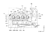
次に、光走査装置200について説明する。図2(a)は、光走査装置200の構成を示す斜視図であり、図2(b)は光走査装置200の断面図である。尚、以下の説明において、回転多面鏡203の回転軸方向をZ軸方向、光ビームの走査方向である主走査方向又は反射ミラーの長手方向をX軸方向、X軸及びZ軸に垂直な方向をY軸方向とする。
[Outline of optical scanning device]
Next, the
図2(a)に示すように、光走査装置200の光学箱201の外壁には、光源ユニット202Y、202M、202C、202Bkが取り付けられている。光源ユニット202Yは、感光ドラム102Yを露光するレーザ光LYを出射し、光源ユニット202Mは、感光ドラム102Mを露光するレーザ光LMを出射する。また、光源ユニット202Cは、感光ドラム102Cを露光するレーザ光LCを出射し、光源ユニット202Bkは、感光ドラム102Bkを露光するレーザ光LBkを出射する。
As shown in FIG. 2A,
光源ユニット202Y、202M、202C、202Bkは互いに近接して配置されている。ここで、回転多面鏡203の回転軸を法線として回転多面鏡203を横切る平面を仮想平面と定義する。光源ユニット202Yから出射されるレーザ光LY及び光源ユニット202Bkから出射されるレーザ光LBkは、仮想平面に対して重力方向上側から斜めに入射する光路をとって回転多面鏡203の反射面に入射する。一方、光源ユニット202Cから出射されるレーザ光LC及び光源ユニット202Mから出射されるレーザ光LMは、上述した仮想平面に対して重力方向下側から斜めに入射する光路をとって回転多面鏡203の反射面に入射する。
The
図2(a)に示すように、光学箱201の中央部には4つの反射面を備える回転多面鏡203が設置されている。画像形成時、回転多面鏡203は、図2(a)の点線で示す回転軸をR1方向に回転する。
As shown in FIG. 2A, a
光源ユニット202Yから出射されたレーザ光LYは、回転多面鏡203の反射面に入射する。レーザ光LYは、回転多面鏡203の反射面によって、図2(a)に示すA側に偏向(反射)される。光源ユニット202Mから出射されたレーザ光LMは、レーザ光LYが入射する回転多面鏡203の反射面と同一の反射面に入射する。レーザ光LMは、回転多面鏡203の反射面によって、レーザ光LYと同一側(A側)に偏向される。
The laser beam LY emitted from the
一方、光源ユニット202Bkから出射されたレーザ光LBkは、レーザ光LY及びLMが入射する反射面とは異なる反射面に入射する。レーザ光LBkは、回転多面鏡203の反射面によって、図2(a)に示すB側に偏向される。光源ユニット202Cから出射されたレーザ光LCは、レーザ光LBkが入射する回転多面鏡203の反射面と同一の反射面に入射する。レーザ光LCは、回転多面鏡203の反射面によってレーザ光LBkと同一側(B側)に偏向される。
On the other hand, the laser beam LBk emitted from the light source unit 202Bk is incident on a reflection surface different from the reflection surface on which the laser beams LY and LM are incident. The laser beam LBk is deflected toward the B side shown in FIG. The laser beam LC emitted from the
回転多面鏡203によって偏向されたレーザ光LY及びLMは、+X方向に移動するレーザ光となる。即ち、回転する回転多面鏡203によって偏向されることによって、レーザ光LYは+X方向に感光ドラム102Yを走査するレーザ光となり、レーザ光LMは感光ドラム102Mを+X方向に走査するレーザ光となる。
The laser beams LY and LM deflected by the
一方、回転多面鏡203によって偏向されたレーザ光LBk及びLCは、−X方向に移動するレーザ光となる。即ち、回転する回転多面鏡203によって偏向されることによって、レーザ光LBkは−X方向に感光ドラム102Bkを走査するレーザ光となり、レーザ光LCは感光ドラム102Cを−X方向に走査するレーザ光となる。
On the other hand, the laser beams LBk and LC deflected by the
続いて、図2(b)を用いて回転多面鏡203によって偏向されたレーザ光LY、LM、LC、LBkの光路について説明する。図2(b)に示すように、光学箱201の内部には、回転多面鏡203、レンズ206、207、208、209、210、211、反射ミラー212、213、214、215、216、217等の光学部材が収容される。光学箱201の上部の開放面には、更に、回転多面鏡203、上述した各レンズ、及び各反射ミラーを防塵するためのカバー218が取り付けられる。
Next, the optical paths of the laser beams LY, LM, LC, and LBk deflected by the
回転多面鏡203によって偏向されたレーザ光LYは、レンズ206及びレンズ207を通過した後、反射ミラー212に入射する。反射ミラー212は、入射したレーザ光LYを感光ドラム102Yに向かって反射する。カバー218には、反射ミラー212が反射したレーザ光LYを通過させる開口219が形成されている。開口219は、レーザ光LYを通過させる透明な透明窓である防塵窓223によって閉塞されている。防塵窓223を通過したレーザ光LYは、感光ドラム102Y上に結像する。
The laser beam LY deflected by the
回転多面鏡203によって偏向されたレーザ光LMは、レンズ206を通過した後、反射ミラー213に入射する。反射ミラー213は、入射したレーザ光LMを反射ミラー214に向かって反射する。反射ミラー213によって反射されてレーザ光LMは、レンズ208を通過して反射ミラー214に入射する。反射ミラー214は、入射したレーザ光LMを感光ドラム102Mに向かって反射する。カバー218には、反射ミラー214が反射したレーザ光LMを通過させる開口220が形成されている。その開口220は、レーザ光LMを通過させる透明の防塵窓224によって閉塞されている。防塵窓224を通過したレーザ光LMは、感光ドラム102Mに結像する。
The laser beam LM deflected by the
回転多面鏡203によって偏向されたレーザ光LBkは、レンズ209及びレンズ210を通過した後、反射ミラー215に入射する。反射ミラー215は、入射したレーザ光LBkを感光ドラム102Bkに向かって反射する。カバー218には、反射ミラー215が反射したレーザ光LBkを通過させる開口222が形成されている。開口222は、レーザ光LBkを通過させる透明の防塵窓226によって閉塞されている。防塵窓226を通過したレーザ光LBkは、感光ドラム102Bk上に結像する。
The laser beam LBk deflected by the rotating
回転多面鏡203によって偏向されたレーザ光LCは、レンズ209を通過した後、反射ミラー216に入射する。反射ミラー216は、入射したレーザ光LCを反射ミラー217に向かって反射する。反射ミラー216によって反射されたレーザ光LCは、レンズ211を通過して反射ミラー217に入射する。反射ミラー217は、入射したレーザ光LCを感光ドラム102Cに向かって反射する。カバー218には、反射ミラー217が反射したレーザ光LCを通過させる開口221が形成されている。開口221は、レーザ光LCを通過させる透明の防塵窓225によって閉塞されている。防塵窓225を通過したレーザ光LCは、感光ドラム102C上に結像する。
The laser beam LC deflected by the
[カバーの概要]
カバー218について、図6(a)を用いて説明する。なお、図6(a)の詳細については後述する。図2(b)に示すように、光学箱201は、カバー218を取り付けることにより、光学箱201内部の密閉性を確保している。図6(a)に示すように、カバー218には複数のフック部218aが設けられている。そして、図3に示すように、カバー218は、光学箱201の外壁に設けられた複数の突起220aに、複数のフック部218aそれぞれを係合させるスナップフィット構造によって、光学箱201に取り付けられる。なお、図6(a)に示すように、カバー218には、光学箱201の内側に向かって窪んだ凹部218bと、光学箱201の外側(シャッタ300側)に向かって突出する凸部218c、218dが設けられている。
[Overview of cover]
The
[シャッタの概要]
続いて、シャッタ300について説明する。シャッタ300は、図6(a)に示すカバー218に設けられた防塵窓223、224、225、226にトナーなどの異物が付着しないようにするための部材である。画像形成装置100のメンテナンスをするために、メンテナンス用の扉を開いてプロセスカートリッジ101を着脱する場合に、プロセスカートリッジ101の着脱によって、プロセスカートリッジ101からトナーが飛散する場合がある。そのため、少なくともプロセスカートリッジ101を交換する場合は、シャッタ300がカバー218の防塵窓223、224、225、226を覆った状態にすることが望ましい。
[Outline of shutter]
Next, the
図3は、カバー218を覆うように、光走査装置200に取り付けられたシャッタ300を示す斜視図である。シャッタ300は、カバー218に対向する一枚の板状の樹脂部材であり、光走査装置200のカバー218の上面に設けられている。シャッタ300は、光走査装置のカバー218に設けられた4ヶ所のガイド爪228によって、外れないようにガイドされており、カバー218の防塵窓223、224、225、226を覆う部材である。シャッタ300は、防塵窓223を通過したレーザ光LYを通過させる開口323、防塵窓224を通過したレーザ光LMを通過させる開口324、防塵窓225を通過したレーザ光LCを通過させる開口325を有する。更に、シャッタ300は、防塵窓226を通過したレーザ光LBkを通過させる開口326を有する。
FIG. 3 is a perspective view showing the
また、シャッタ300には、後述する弾性体であるバネ310を取り付けるための長穴301が形成されている。更に、シャッタ300には、長穴302、303が形成され、カバー218の凸部218cは長穴302に挿入され、カバー218の凸部218dは、長穴303に挿入されている。これにより、長穴302、303、凸部218c、218dは、長穴302と凸部218c、長穴303と凸部218dとがそれぞれ係合する係合機構であり、シャッタ300の移動方向をY軸方向に制限するガイド部材として機能する。
The
シャッタ300は、バネ310によって常に開口を遮蔽する方向に付勢されている。通常の画像形成時には、後述する移動機構によって、シャッタ300は開放方向に押し込まれている。一方、メンテナンス時にはシャッタ300は遮蔽位置に戻って、カバー218のYMCK全色の防塵窓223、224、225、226を同時に塞ぎ、トナーなどの飛散物が光走査装置200の防塵窓に付着することを防ぐ。シャッタ300の長穴302、303は、シャッタ300のY軸に平行な方向に長い穴であるため、長穴302、303、凸部218c、218dによってシャッタ300の移動はY軸に平行な往復方向に規制される。なお、シャッタ300は、画像形成装置側に取り付けられてもよい。また、シャッタ300側に上述した凸部を設け、カバー218側に上述した開口に相当する凹部(挿入部)を設け、シャッタ300側に設けた凸部を凹部に挿入してガイド部材としてもよい。
The
[シャッタ移動機構の概要]
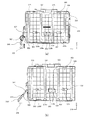
図4は、シャッタ移動機構、シャッタ、及び光走査装置を上方向から見た上面図である。図4(a)は、シャッタ300が閉じ、カバー218の防塵窓223、224、225、226がシャッタ300により遮蔽されている状態を示している。一方、図4(b)は、シャッタ300が開き、レーザ光の光路上から退避した位置に位置しているので、カバー218の防塵窓223、224、225、226がシャッタ300により遮蔽されず、開放されている状態を示している。なお、シャッタ移動機構は、画像形成装置100側に設けられている。シャッタ移動機構の一部を構成する回動機構は、回転機構と押圧部309から構成されている。回転機構は、図4(a)に示すように、回転軸305、回転部306、レバー307、レバー308によって構成される。回転部306、レバー307、308は1つの回転部材を構成し、回転部306からは、レバー307、308が延出する。そして、回転部306、レバー307、レバー308によって構成される回転部材は、回転軸305を回転中心として、時計回り方向、及び反時計回り方向に回転することができる。
[Outline of shutter moving mechanism]
FIG. 4 is a top view of the shutter moving mechanism, the shutter, and the optical scanning device as viewed from above. FIG. 4A shows a state where the
続いて、図4を用いてシャッタ移動機構の一部を構成するバネ310について説明する。図4(a)に示すように、カバー218の凹部218bには、コイルバネなどのバネ310の一端が係合する係合部218eが設けられている。一方、図4(b)に示すように、シャッタ300には、バネ310の他端側が係合する係合部304が設けられている。即ち、カバー218とシャッタ300は、バネ310によって連結され、シャッタ300はバネ310によって、常に開口を遮蔽する方向に付勢されている。なお、本実施例では、バネ310は、カバー218とシャッタ300とを連結しているが、光学箱201とシャッタ300とを連結する構成でもよい。
Next, the
(シャッタ移動機構の動作)
次に、図4を用いてシャッタ移動機構(シャッタ開閉機構)の動作について説明する。
(Operation of shutter moving mechanism)
Next, the operation of the shutter moving mechanism (shutter opening / closing mechanism) will be described with reference to FIG.
図4(a)は、不図示の回収トナー容器を画像形成装置100に装着する前の状態をシャッタ300の上方向から見た上面図である。本実施例では、図4(a)の状態は、バネ310が縮み、シャッタ300が光走査装置200からのレーザ光を遮光する、シャッタ300が閉じている状態を示している。そのため、図4(a)において、シャッタ300は、カバー218に設けられた防塵窓223、224、225、226を覆っており、仮にレーザ光LY、LM、LC、LBkを出射されたとしても、それらのレーザ光はシャッタ300に遮られる。
FIG. 4A is a top view of the state before the collection toner container (not shown) is mounted on the
一方、図4(b)は、不図示の回収トナー容器が画像形成装置100に装着された状態をシャッタ300の上方向から見た上面図である。図4(a)の状態から、不図示の回収トナー容器を画像形成装置100に装着すると、回収トナー容器に設けられた押圧部309の斜面が図中、矢印方向に移動することにより、レバー307、308が時計回り方向(図中、矢印方向)に回転する。その結果、バネ310は伸ばされ、シャッタ300は開放方向(図4(a)に示す矢印方向)に移動して、図4(b)に示す状態となる。本実施例では、図4(b)の状態は、シャッタ300が光走査装置200からのレーザ光を遮光しない、シャッタ300が開放されている状態を示している。そのため、図4(b)において、シャッタ300は、カバー218に設けられた防塵窓223、224、225、226を覆っておらず、レーザ光LY、LM、LC、LBkは、シャッタ300の開口323、324、325、326を通過することができる。
On the other hand, FIG. 4B is a top view of the state in which a collection toner container (not shown) is mounted on the
一方、メンテナンス時には、必ず不図示の回収トナー容器が外されるため、押圧部309による押し込み力がなくなるため、バネ310によって、シャッタ300は遮蔽位置(図4(a)に示す状態)へ戻る。本実施例では、レバー307、308を回転させる方法として不図示の回収トナー容器を用いているが、メンテナンス時にプロセスカートリッジを外すよりも先に行う操作であれば、必ずしも回収トナー容器である必要はない。
On the other hand, at the time of maintenance, since the collected toner container (not shown) is surely removed, the pushing force by the
[カバーの構成]
図5(a)は、本実施例におけるカバー218の構成を示す図であり、カバー218を光学箱201側から見た斜視図である。図5(a)において、カバー218には、光学箱201の外壁に設けられた突起220aを係合させて、スナップフィット構造を構成する複数のフック部218aが設けられている。また、カバー218には、防塵窓223、224、225、226が設けられている。更に、カバー218には、光学箱201への装着時に、光学箱201の外周縁と対向する部分全周に、ポリオレフィン系のホットメルト接着剤(以下、「ホットメルト」という)によるシール部250が射出成型によって形成されている。また、射出成型時にホットメルトを注入するゲート部250aが、図5(a)では4か所設けられているが、ゲート部250aは、少なくとも1か所以上設けられていればよい。
[Composition of cover]
FIG. 5A is a diagram illustrating the configuration of the
シール部250は、形成されたカバー218と、カバー218に当接した型との間の空間に、ポリオレフィン系のホットメルトを射出することにより、カバー218上に形成される。図5(b)は、カバー218を、図5(a)の図中に示す矢印の位置で切断した図であり、カバー218とシール部250の関係を示す断面図である。図5(b)において、カバー218には、溝部218fが設けられており、この溝部218fにホットメルトを充填することにより、シール部250が形成される。溝部218fの中には、更に幅が狭くて深さの浅いアンカー溝218gが設けられ、カバー218とシール部250の接触面積を拡大させている。これにより、シール部材がカバー218から意図せず剥がれたりしないように、カバー218とシール部250の間の接着性を確保している。また、シール部250の表面には、凹状の溝部が形成され、この溝部に光学箱201の外周縁が挿入されることにより、光学箱201の密閉性が確保される。
The
[ゲート部の構成]
図6(a)は、本実施例におけるカバー218の構成を示す図であり、カバー218を上方向から見た斜視図である。カバー218には、複数のフック部218aが設けられ、光学箱201の外壁に設けられた複数の突起220aに、複数のフック部218aそれぞれを係合させることによって、カバー218は光学箱201に取り付けられる。また、カバー218には、光学箱201の内側に向かって窪んだ凹部218bと、光学箱201の外側に向かって突出する凸部218c、218dが設けられている。そして、凸部218c、218dを、それぞれシャッタ300の長穴302、303と係合させることによって、シャッタ300の移動方向を所定の方向に制限するガイド部材として機能する。更に、カバー218の上面には、シール部250の射出成型時に成型材料を注入するゲート部250aが4ヶ所設けられている。本実施例のように、細くて長い空間から構成されるシール部250にホットメルトを充填しようとする場合には、ホットメルトの流動性を高めるために、ホットメルトを射出する射出ノズルにもヒータを設けて、射出材料を高温状態に維持している。このため、射出ノズルは大型化してしまう。一方、通常、カバー218には、その周縁に沿って、光学箱201側に立ち壁を設けたり、光学箱201に固定するための突起(例えば、フック部218a)を設けたりすることが多い。図7は、カバー218の光学箱側に設けられたゲート部250aに、ホットメルトを注入する注入口を設けた場合の図であり、ハッチングされた円形部分は、ホットメルトを射出する射出ノズルのノズル範囲を示している。前述したように、射出ノズルにはヒータが設けられているため、ノズル形状が大きくなり、図7に示すように、カバー218の外周部分に設けられたフック部218a等の突起と射出ノズルが干渉する場合がある。そのため、これを避けるため、本実施例では、ゲート部250aのホットメルトの注入口をカバー218の上面に設けている。
[Configuration of gate part]
FIG. 6A is a diagram illustrating the configuration of the
ところで、ホットメルトを射出したときに、ホットメルトの流動性が高いために、糸を引くように成型材料が溜まって、凸状の形状をしたゲート跡として、ゲート部250aの注入口に突出する場合がある。図8は、ゲート部250aを含んだ部分で、カバー218とシャッタ300を切断した断面図である。図8において、シャッタ300は開放状態で、光学箱201からのレーザ光である走査光は、カバー218に設けられた防塵窓223、224、225、226を介して、シャッタ300の開口323、324、325、326を通過する。図8(a)はゲート部250aの注入口をカバー218の表面に設けた場合のゲート跡を、図8(b)はゲート部250aの注入口をカバー218の表面から一段下げた面(一段低い面)に設けた場合のゲート跡を示す図である。図8(a)のようにゲート部250aの表面が周囲のカバー表面と同一面であると、わずかでもゲート跡がシャッタ300側に突出すると、ゲート跡がシャッタ300と干渉して、シャッタ300の図中、矢印で示すシャッタ移動方向の動きを妨げてしまう。この場合、例えば刃物でゲート跡の突出部をカットして平らにする等の二次加工が必要となり、手間とコストが発生してしまう。
By the way, when hot melt is injected, since the hot melt has high fluidity, the molding material accumulates so as to pull the yarn, and protrudes into the injection port of the
そこで、本実施例では、手間とコストを発生させないために、図6(b)に示すように、ゲート部250aをカバー218の表面に設けている。図6(b)は、図6(a)において円で囲まれたカバー218の部分を拡大した図である。図6(b)では、ゲート部250aをカバー218の表面に設けられた凹部に設け、更に、ゲート部250aの中央には、ホットメルトの注入口250bが設けられている。図6(b)の状態を断面図で示したものが図8(b)であり、図8(b)に示すように、ゲート部250aの表面をカバー218の表面から一段低い凹部に設けていることがわかる。これにより、もしゲート跡が注入口250bから突出したとしても、シャッタ300と干渉することがなく、図中、矢印で示すシャッタ300の移動方向の動きを妨げることがなくなる。具体的には、本実施例では、例えばゲート跡が1mm突出したとしても、シャッタ300と干渉することはなく、1mmは、成型時の吐出制御で十分管理可能な突出量であり、二次加工などを必要とすることはない。
Therefore, in this embodiment, in order to avoid labor and cost, the
以上説明したように、本実施例によれば、光走査装置の高い防塵性能と、その上部を覆うシャッタの確実な動作を保証することができる。射出成型によるシール部250を一体的に設けたカバー部材と、そのカバーの上面をスライドして移動するシャッタを組み合わせた光走査装置において、カバーの表面より一段低い面である凹部にゲート部を設ける。これにより、凸状のゲート跡がゲート部から突出したとしても、シャッタに干渉してシャッタのスライド動作を妨げることはなく、シャッタを確実に開閉させることができ、シャッタの滑らかな動きを確保することができる。
As described above, according to this embodiment, it is possible to guarantee the high dustproof performance of the optical scanning device and the reliable operation of the shutter that covers the upper portion. In an optical scanning device that combines a cover member that is integrally provided with a
[ゲート部の構成]
図9は、図6(a)において円で囲まれたカバー218の部分を拡大した図であり、本実施例におけるゲート部の構成を示す図である。図9では、ゲート部250aの中央に凹部を設け、この凹部の中に、シール部250の成型材料の注入口250cを設けている。本実施例の図9では、実施例1の図6(b)と比べて、ホットメルトが注入される注入口250cの表面が、一段低い位置となっている。したがって、本実施例では、実施例1の図8(b)に示すゲート面の位置よりも、更に低い位置に注入口250cが設けられることになる。これにより、限られたスペースの中で、ゲート跡の突出に対し、シャッタ300へのクリアランスをより大きくかせぐことができる。
[Configuration of gate part]
FIG. 9 is an enlarged view of a portion of the
以上説明したように、本実施例によれば、光走査装置の高い防塵性能と、その上部を覆うシャッタの確実な動作を保証することができる。 As described above, according to this embodiment, it is possible to guarantee the high dustproof performance of the optical scanning device and the reliable operation of the shutter that covers the upper portion.
実施例1、2では、ゲート跡がシャッタ300に干渉しないように、ゲート部250aのホットメルト注入口をカバー218の表面よりも低い位置に設ける例について説明した。実施例3では、ゲート跡がシャッタ300に干渉しないようなシャッタ300の構成について説明する。なお、本実施例におけるカバー218の構成は、図6(a)と同様であり、説明を省略する。
In the first and second embodiments, the example in which the hot melt injection port of the
[シャッタの構成]
図10は、本実施例のシャッタ300の構成を示す図であり、シャッタ300をカバー218側から見た斜視図である。図10において、シャッタ300は、前述したように、防塵窓223、224、225、226を通過したレーザ光を通過させる開口323、324、325、326を備えている。また、シャッタ300には、バネ310を取り付けるための長穴301、及びカバー218の凸部218c、218dと係合され、ガイド部材として機能する長穴302、303を備えている。更に、本実施例では、シャッタ300は、カバー218のゲート部250aに対向する位置に凹部300eが設けられており、図10には、図6(a)に示すゲート部250aに対応して、凹部300eは4か所設けられている。凹部300eは、ゲート部250aに形成されるゲート跡がシャッタ300に干渉しないような深さと幅(シャッタ移動方向と直交する方向の長さ)を有する。これにより、カバー218のゲート部250aに形成されたゲート跡がシャッタ300に当接することにより、干渉することがなくなる。本実施例では、ゲート部250aは実施例1で説明した構成に基づいて説明したが、実施例2の場合のゲート部250aの構成についても適用することができる。更に、凹部300eの深さと幅を対応させることにより、例えばゲート部250aを、カバー218と同じ高さで、カバー218の表面上に設けた場合にも、本実施例を適用することができる。
[Configuration of shutter]
FIG. 10 is a diagram illustrating a configuration of the
以上説明したように、本実施例によれば、光走査装置の高い防塵性能と、その上部を覆うシャッタの確実な動作を保証することができる。 As described above, according to this embodiment, it is possible to guarantee the high dustproof performance of the optical scanning device and the reliable operation of the shutter that covers the upper portion.
200 光走査装置
201 光学箱
218 カバー
250a ゲート部
300 シャッタ
200
Claims (8)
前記光源より出射された光ビームを偏向する偏向手段と、
前記偏向手段によって偏向した光ビームを感光体に導く光学部材と、
前記光源が取り付けられ、前記偏向手段、及び前記光学部材を内部に収容する光学箱と、
前記光ビームを通過させる透明窓を有し、前記光学箱の開放面を覆うカバーと、
前記感光体と前記カバーとの間に配置され、前記透明窓を通過した光ビームの光路上から退避した位置と前記透明窓を覆う位置との間を移動するシャッタと、
を備えた光走査装置であって、
前記カバーは前記光学箱と当接する部分に該カバーと一体的に成型されたシール部材を備え、
前記シール部材を成型するためのゲート部は、前記カバーの前記シャッタと対向する面に設けられた凹部に設けられていることを特徴とする光走査装置。 A light source;
Deflecting means for deflecting the light beam emitted from the light source;
An optical member for guiding the light beam deflected by the deflecting means to the photosensitive member;
An optical box to which the light source is attached, the deflection means, and the optical member are housed therein;
A cover having a transparent window through which the light beam passes, and covering an open surface of the optical box;
A shutter that is disposed between the photoconductor and the cover and moves between a position retracted from an optical path of a light beam that has passed through the transparent window and a position that covers the transparent window;
An optical scanning device comprising:
The cover includes a seal member molded integrally with the cover at a portion that contacts the optical box,
An optical scanning device, wherein a gate portion for molding the seal member is provided in a concave portion provided on a surface of the cover facing the shutter.
前記シール部材を成型するために成型材料を注入する注入口は、前記更なる凹部に設けられていることを特徴とする請求項1又は2に記載の光走査装置。 The recess has a further recess therein;
The optical scanning device according to claim 1, wherein an injection port for injecting a molding material to mold the seal member is provided in the further recess.
前記光源より出射された光ビームを偏向する偏向手段と、
前記偏向手段によって偏向した光ビームを感光体に導く光学部材と、
前記光源が取り付けられ、前記偏向手段、及び前記光学部材を内部に収容する光学箱と、
前記光ビームを通過させる透明窓を有し、前記光学箱の開放面を覆うカバーと、
前記感光体と前記カバーとの間に配置され、前記透明窓を通過した光ビームの光路上から退避した位置と前記透明窓を覆う位置との間を移動するシャッタと、
を備えた光走査装置であって、
前記カバーは、前記光学箱と当接する部分に該カバーと一体的に成型されたシール部材を成型するための1つ以上のゲート部を備え、
前記シャッタは、前記ゲート部の各々と対向する位置に凹部を備えていることを特徴とする光走査装置。 A light source;
Deflecting means for deflecting the light beam emitted from the light source;
An optical member for guiding the light beam deflected by the deflecting means to the photosensitive member;
An optical box to which the light source is attached, the deflection means, and the optical member are housed therein;
A cover having a transparent window through which the light beam passes, and covering an open surface of the optical box;
A shutter that is disposed between the photoconductor and the cover and moves between a position retracted from an optical path of a light beam that has passed through the transparent window and a position that covers the transparent window;
An optical scanning device comprising:
The cover includes one or more gate portions for molding a seal member molded integrally with the cover at a portion in contact with the optical box,
The optical scanning device, wherein the shutter includes a concave portion at a position facing each of the gate portions.
前記光走査装置からの光ビームにより走査される前記感光体と、
前記感光体上に形成された静電潜像を現像する現像手段と、
を備えることを特徴とする画像形成装置。 An optical scanning device according to any one of claims 1 to 6,
The photoconductor scanned by a light beam from the optical scanning device;
Developing means for developing an electrostatic latent image formed on the photoreceptor;
An image forming apparatus comprising:
Priority Applications (1)
| Application Number | Priority Date | Filing Date | Title |
|---|---|---|---|
| JP2013185207A JP6188501B2 (en) | 2013-09-06 | 2013-09-06 | Optical scanning apparatus and image forming apparatus |
Applications Claiming Priority (1)
| Application Number | Priority Date | Filing Date | Title |
|---|---|---|---|
| JP2013185207A JP6188501B2 (en) | 2013-09-06 | 2013-09-06 | Optical scanning apparatus and image forming apparatus |
Publications (2)
| Publication Number | Publication Date |
|---|---|
| JP2015051567A JP2015051567A (en) | 2015-03-19 |
| JP6188501B2 true JP6188501B2 (en) | 2017-08-30 |
Family
ID=52700978
Family Applications (1)
| Application Number | Title | Priority Date | Filing Date |
|---|---|---|---|
| JP2013185207A Active JP6188501B2 (en) | 2013-09-06 | 2013-09-06 | Optical scanning apparatus and image forming apparatus |
Country Status (1)
| Country | Link |
|---|---|
| JP (1) | JP6188501B2 (en) |
Family Cites Families (11)
| Publication number | Priority date | Publication date | Assignee | Title |
|---|---|---|---|---|
| CA1190019A (en) * | 1982-07-12 | 1985-07-09 | Jobst U. Gellert | Injection molding hot tip seal |
| JPH0347853Y2 (en) * | 1986-01-24 | 1991-10-14 | ||
| JP3365843B2 (en) * | 1993-12-08 | 2003-01-14 | オリンパス光学工業株式会社 | Lens holding device |
| JP2709054B2 (en) * | 1997-03-07 | 1998-02-04 | 日立マクセル株式会社 | Disk Cartridge |
| JP2004262118A (en) * | 2003-03-03 | 2004-09-24 | Ricoh Co Ltd | Writing device and image forming apparatus |
| JP4662032B2 (en) * | 2005-03-23 | 2011-03-30 | セイコーエプソン株式会社 | Liquid ejector |
| JP4348638B2 (en) * | 2006-03-08 | 2009-10-21 | 村田機械株式会社 | Roller member and image forming apparatus |
| JP2007316024A (en) * | 2006-05-29 | 2007-12-06 | Nsk Ltd | Rolling bearing |
| JP5264555B2 (en) * | 2008-03-06 | 2013-08-14 | キヤノン株式会社 | Scanning optical device |
| JP5449954B2 (en) * | 2009-09-29 | 2014-03-19 | Ntn株式会社 | Hydrodynamic bearing device |
| JP5825548B2 (en) * | 2011-05-23 | 2015-12-02 | 株式会社リコー | Optical scanning apparatus and image forming apparatus |
-
2013
- 2013-09-06 JP JP2013185207A patent/JP6188501B2/en active Active
Also Published As
| Publication number | Publication date |
|---|---|
| JP2015051567A (en) | 2015-03-19 |
Similar Documents
| Publication | Publication Date | Title |
|---|---|---|
| US8019240B2 (en) | Developing apparatus, process cartridge, and electrophotographic image forming apparatus | |
| CN109901287B (en) | Optical scanning device and image forming apparatus | |
| JP6288995B2 (en) | Optical scanning apparatus and image forming apparatus | |
| US10474063B2 (en) | Image forming apparatus having movable shutter member | |
| JP5760354B2 (en) | Image forming apparatus | |
| JP5464085B2 (en) | Image forming apparatus | |
| JP6012765B2 (en) | Image forming apparatus | |
| KR100657282B1 (en) | Developing unit and electrophotograhpic image forming apparatus with the same | |
| JP6188501B2 (en) | Optical scanning apparatus and image forming apparatus | |
| US20210263465A1 (en) | Image forming apparatus | |
| JP6173147B2 (en) | Optical scanning apparatus and image forming apparatus | |
| JP6370060B2 (en) | Image forming apparatus | |
| JP6074262B2 (en) | Image forming apparatus | |
| JP5825548B2 (en) | Optical scanning apparatus and image forming apparatus | |
| JP6597513B2 (en) | Detachable unit and image forming apparatus having the same | |
| JP5253613B2 (en) | Image forming apparatus | |
| JP6226651B2 (en) | Optical scanning apparatus and image forming apparatus | |
| JP6021635B2 (en) | Image forming apparatus | |
| JP6739917B2 (en) | Image forming apparatus and optical scanning apparatus | |
| JP2023132526A (en) | Optical scanner and image forming apparatus | |
| JP2014126828A (en) | Image forming apparatus | |
| JP2017102238A (en) | Image forming apparatus |
Legal Events
| Date | Code | Title | Description |
|---|---|---|---|
| RD03 | Notification of appointment of power of attorney |
Free format text: JAPANESE INTERMEDIATE CODE: A7423 Effective date: 20160215 |
|
| RD04 | Notification of resignation of power of attorney |
Free format text: JAPANESE INTERMEDIATE CODE: A7424 Effective date: 20160215 |
|
| A621 | Written request for application examination |
Free format text: JAPANESE INTERMEDIATE CODE: A621 Effective date: 20160906 |
|
| A977 | Report on retrieval |
Free format text: JAPANESE INTERMEDIATE CODE: A971007 Effective date: 20170628 |
|
| TRDD | Decision of grant or rejection written | ||
| A01 | Written decision to grant a patent or to grant a registration (utility model) |
Free format text: JAPANESE INTERMEDIATE CODE: A01 Effective date: 20170704 |
|
| A61 | First payment of annual fees (during grant procedure) |
Free format text: JAPANESE INTERMEDIATE CODE: A61 Effective date: 20170801 |
|
| R151 | Written notification of patent or utility model registration |
Ref document number: 6188501 Country of ref document: JP Free format text: JAPANESE INTERMEDIATE CODE: R151 |