JP6187589B2 - Trunk muscle contraction detector - Google Patents
Trunk muscle contraction detector Download PDFInfo
- Publication number
- JP6187589B2 JP6187589B2 JP2015530774A JP2015530774A JP6187589B2 JP 6187589 B2 JP6187589 B2 JP 6187589B2 JP 2015530774 A JP2015530774 A JP 2015530774A JP 2015530774 A JP2015530774 A JP 2015530774A JP 6187589 B2 JP6187589 B2 JP 6187589B2
- Authority
- JP
- Japan
- Prior art keywords
- data
- unit
- component
- muscle contraction
- trunk muscle
- Prior art date
- Legal status (The legal status is an assumption and is not a legal conclusion. Google has not performed a legal analysis and makes no representation as to the accuracy of the status listed.)
- Active
Links
Images


Classifications
-
- A—HUMAN NECESSITIES
- A61—MEDICAL OR VETERINARY SCIENCE; HYGIENE
- A61B—DIAGNOSIS; SURGERY; IDENTIFICATION
- A61B5/00—Measuring for diagnostic purposes; Identification of persons
- A61B5/103—Detecting, measuring or recording devices for testing the shape, pattern, colour, size or movement of the body or parts thereof, for diagnostic purposes
- A61B5/11—Measuring movement of the entire body or parts thereof, e.g. head or hand tremor, mobility of a limb
- A61B5/1107—Measuring contraction of parts of the body, e.g. organ, muscle
-
- A—HUMAN NECESSITIES
- A61—MEDICAL OR VETERINARY SCIENCE; HYGIENE
- A61B—DIAGNOSIS; SURGERY; IDENTIFICATION
- A61B5/00—Measuring for diagnostic purposes; Identification of persons
- A61B5/02—Detecting, measuring or recording pulse, heart rate, blood pressure or blood flow; Combined pulse/heart-rate/blood pressure determination; Evaluating a cardiovascular condition not otherwise provided for, e.g. using combinations of techniques provided for in this group with electrocardiography or electroauscultation; Heart catheters for measuring blood pressure
- A61B5/024—Detecting, measuring or recording pulse rate or heart rate
- A61B5/02405—Determining heart rate variability
-
- A—HUMAN NECESSITIES
- A61—MEDICAL OR VETERINARY SCIENCE; HYGIENE
- A61B—DIAGNOSIS; SURGERY; IDENTIFICATION
- A61B5/00—Measuring for diagnostic purposes; Identification of persons
- A61B5/08—Detecting, measuring or recording devices for evaluating the respiratory organs
- A61B5/0816—Measuring devices for examining respiratory frequency
-
- A—HUMAN NECESSITIES
- A61—MEDICAL OR VETERINARY SCIENCE; HYGIENE
- A61B—DIAGNOSIS; SURGERY; IDENTIFICATION
- A61B5/00—Measuring for diagnostic purposes; Identification of persons
- A61B5/72—Signal processing specially adapted for physiological signals or for diagnostic purposes
- A61B5/7203—Signal processing specially adapted for physiological signals or for diagnostic purposes for noise prevention, reduction or removal
- A61B5/7207—Signal processing specially adapted for physiological signals or for diagnostic purposes for noise prevention, reduction or removal of noise induced by motion artifacts
-
- A—HUMAN NECESSITIES
- A61—MEDICAL OR VETERINARY SCIENCE; HYGIENE
- A61B—DIAGNOSIS; SURGERY; IDENTIFICATION
- A61B5/00—Measuring for diagnostic purposes; Identification of persons
- A61B5/72—Signal processing specially adapted for physiological signals or for diagnostic purposes
- A61B5/7235—Details of waveform analysis
-
- A—HUMAN NECESSITIES
- A61—MEDICAL OR VETERINARY SCIENCE; HYGIENE
- A61B—DIAGNOSIS; SURGERY; IDENTIFICATION
- A61B5/00—Measuring for diagnostic purposes; Identification of persons
- A61B5/72—Signal processing specially adapted for physiological signals or for diagnostic purposes
- A61B5/7271—Specific aspects of physiological measurement analysis
- A61B5/7278—Artificial waveform generation or derivation, e.g. synthesising signals from measured signals
Description
本発明は体幹筋収縮検出装置に関する。 The present invention relates to a trunk muscle contraction detection apparatus.
従来から、人体に関する特徴量をセンシングして人体の動き又は状態を検出する技術が知られている。例えば、特許文献1には、携帯装置に搭載された加速度センサからの出力を解析して人体の動きを判定する構成が開示されている。人体に装着された携帯装置の加速度センサから得られた特徴量が参照データと比較され、比較結果に基づいて、腕を振る、歩行する等といった体動が判別される。
2. Description of the Related Art Conventionally, a technique for detecting a motion or state of a human body by sensing a feature amount related to the human body is known. For example,
また、特許文献2には、心拍間隔の周波数解析を行い、睡眠深度、自律神経(交感神経、副交感神経)活動又は呼吸に特徴的な周波数帯域成分量から、睡眠状態、自律神経状態(疲労状態)又は呼吸状態を推定する構成が開示されている。
In
しかしながら、特許文献1の構成によると、加速度センサが装着された部位の動きが検出されるため、携帯装置は、手に把持された状態では手以外の部位の動きを検出することはできない。また、深呼吸、力みといった変位を伴わない体動は加速度センサに加速度が与えられないため、検出されない。また逆に、乗り物への乗車中等、体動以外の要因によって加速度センサに加速度が与えられた場合には、体動があったものと誤判定されてしまう。
However, according to the configuration of
また、特許文献2の構成では、検出された拍動に基づいて解析が行われるため、加速度センサを用いた場合で問題となるような、検出部位が限定されること、変位のない体動が検出されないこと、体動以外の加速度に影響を受けることといった不都合は解消される。しかしながら、同文献の構成によると、体動を要因とする心拍の周期的変動と、自律神経の働きを要因とする心拍の周期的変動が同じ周波数帯域にあった場合に、これらの要因による変動が区別されない。また、周波数解析に数分程度分のデータが必要であり解析結果を得るのに長時間を要する。そもそも自律神経解析は安静状態における静的なデータの取得を前提とするものであり、一瞬の体動に起因する心拍数変動成分はノイズとして除去される対象となってしまうため、適時な体動検出には適さない。
Further, in the configuration of
そこで、本発明は、拍動データを用いて体動等に伴う体幹筋収縮の発生を正確かつ適時に検出することができる体幹筋収縮検出装置を提供することを課題とする。 Therefore, an object of the present invention is to provide a trunk muscle contraction detecting device that can accurately and timely detect the occurrence of trunk muscle contraction accompanying body motion or the like using pulsation data.
本発明に係る体幹筋収縮検出装置は、拍動間隔データにおける拍動間隔の変化成分を表す変化成分データを取得する変化成分取得部と、変化成分データから、拍動間隔データにおける周期的な振動に対応する振動成分を除去して振動成分除去データを生成する振動成分除去部と、振動成分除去データのうち所定の変動成分を抽出し、抽出された所定の変動成分に基づいて体幹筋収縮の発生を特定する変動成分抽出部とを備えることを特徴とする。 The trunk muscle contraction detection device according to the present invention includes a change component acquisition unit that acquires change component data representing a change component of a beat interval in the beat interval data, and a periodicity in the beat interval data from the change component data. A vibration component removing unit that generates vibration component removal data by removing vibration components corresponding to vibrations, and extracting predetermined fluctuation components from the vibration component removal data, and trunk muscles based on the extracted predetermined fluctuation components And a fluctuation component extraction unit that identifies occurrence of contraction.
本発明に係る体幹筋収縮検出装置によると、拍動間隔データの変化成分データから、呼吸性変動等に起因する振動成分が除去されたデータにおいて、体幹筋収縮に起因する変動成分が抽出されるので、体幹筋収縮を確実に検出することが可能となる。呼吸によっても体幹筋収縮が生じるが、周期的な呼吸はノイズとみなし、以降は体幹筋収縮による変動を呼吸性変動と区別する。 According to the trunk muscle contraction detecting device according to the present invention, the fluctuation component due to trunk muscle contraction is extracted from the data obtained by removing the vibration component due to respiratory fluctuation or the like from the variation component data of the pulsation interval data. Thus, trunk muscle contraction can be reliably detected. Trunk muscle contraction is also caused by respiration, but periodic breathing is regarded as noise, and thereafter, fluctuation due to trunk muscle contraction is distinguished from respiratory fluctuation.
本発明に係る体幹筋収縮検出装置では、所定の変動成分が、拍動間隔データの波形において低下ピークの直後に増加ピークが発生したデータ波形に対応する成分であることが好ましい。 In the trunk muscle contraction detection device according to the present invention, the predetermined fluctuation component is preferably a component corresponding to a data waveform in which an increase peak occurs immediately after the decrease peak in the waveform of the pulsation interval data.
この場合、拍動間隔データにおいて、体幹筋収縮時に特徴的な拍動間隔の変化が変動成分として抽出されるので、高い精度での体幹筋収縮の特定が可能となる。 In this case, in the pulsation interval data, the characteristic change in pulsation interval at the time of trunk muscle contraction is extracted as a fluctuation component, so that trunk muscle contraction can be specified with high accuracy.
本発明に係る体幹筋収縮検出装置では、振動成分が呼吸性変動に基づく成分であることが好ましい。 In the trunk muscle contraction detecting device according to the present invention, the vibration component is preferably a component based on respiratory change.
この場合、拍動間隔データにおいて呼吸性変動が大きい場合でも、呼吸性変動に起因する変化成分が振動成分として確実に除去され、高い精度での体幹筋収縮の特定が可能となる。 In this case, even when the respiratory fluctuation is large in the pulsation interval data, the change component caused by the respiratory fluctuation is reliably removed as the vibration component, and the trunk muscle contraction can be specified with high accuracy.
本発明に係る体幹筋収縮検出装置では、変化成分取得部が、拍動間隔データを補間して拍動間隔データを一定の時間間隔に配置し、補間された拍動間隔データを振動成分除去部に供給する補間処理部を備えることを特徴とする。 In the trunk muscle contraction detection device according to the present invention, the change component acquisition unit interpolates the pulsation interval data, arranges the pulsation interval data at a constant time interval, and eliminates the vibration component from the interpolated pulsation interval data. An interpolation processing unit for supplying to the unit is provided.
この場合、拍動間隔データの補間により、拍動間隔データを一定の時間間隔で切り出すことができるので、拍動間隔データの周波数軸上での処理が可能となる。従って、振動成分除去部に適応フィルタ等を用いることができ、データ処理構成の自由度が向上する。また、短い振動周期の拍動間隔データについて、補間処理が施されることにより、その振動特性が捕捉され易くなるので、振動成分除去の精度を向上することが可能となる。 In this case, since the beat interval data can be cut out at a constant time interval by interpolation of the beat interval data, the beat interval data can be processed on the frequency axis. Therefore, an adaptive filter or the like can be used for the vibration component removal unit, and the degree of freedom of the data processing configuration is improved. Further, by performing interpolation processing on the pulse interval data having a short vibration cycle, the vibration characteristics can be easily captured, so that the accuracy of vibration component removal can be improved.
本発明に係る体幹筋収縮検出装置は、被験者の拍動を検知して拍動間隔データを生成する拍動間隔データ生成手段を備えることを特徴とする。 The trunk muscle contraction detection apparatus according to the present invention includes a pulse interval data generation unit that detects a pulse of a subject and generates beat interval data.
本発明に係る体幹筋収縮検出装置によると、拍動を検知し、その検知出力に基づいて体幹筋収縮を正確かつ適時に検出することが可能となる。 According to the trunk muscle contraction detection device according to the present invention, it is possible to detect pulsation and to detect trunk muscle contraction accurately and in a timely manner based on the detection output.
本発明によれば、拍動データを用いて体動等に伴う体幹筋収縮の発生を正確かつ適時に検出することが可能となる。 ADVANTAGE OF THE INVENTION According to this invention, it becomes possible to detect the generation | occurrence | production of trunk muscle contraction accompanying body movement etc. correctly and timely using pulsation data.
以下、図面を参照して本発明の好適な実施形態について詳細に説明する。なお、各図において、同一要素には同一符号を付して重複する説明を省略する。 DESCRIPTION OF EMBODIMENTS Hereinafter, preferred embodiments of the present invention will be described in detail with reference to the drawings. In addition, in each figure, the same code | symbol is attached | subjected to the same element and the overlapping description is abbreviate | omitted.
(第1実施形態)
まず、図1を用いて、第1実施形態に係る体幹筋収縮検出装置1の構成について説明する。図1は、体幹筋収縮検出装置1の構成を示すブロック図である。本実施形態の体幹筋収縮検出装置1は、拍動間隔データにおける拍動間隔の変化成分データを取得し、変化成分データから周期的な振動に対応する成分を除去して振動成分除去データを生成し、振動成分除去データのうち所定の変動成分を抽出して体幹筋収縮の発生を特定する。以下、各構成要素について詳細に説明する。(First embodiment)
First, the configuration of the trunk muscle
体幹筋収縮検出装置1は、拍動を取得するための拍動センサ20、拍動間隔データを生成するための拍動間隔データ生成ユニット30、及び検出された拍動間隔データに基づいて体幹筋収縮検出のための解析を行う拍動間隔データ解析ユニット40を備える。以下、各構成要素について詳細に説明する。なお、拍動センサ20及び拍動間隔データ生成ユニット30が請求の範囲の拍動間隔データ生成手段として機能する。
The trunk muscle
拍動センサ20は、脈拍を検知するための光電脈波センサ、心拍を検知するための心電センサ、圧電センサ等であればよい。なお、本明細書において、脈拍及び心拍をまとめて拍動というものとする。拍動センサ20は人体に装着される装着型のセンサであってもよいし、ゲームコントローラ又はスマートフォンのような手によって把持される把持型のセンサであってもよい。本実施形態においては、一例として、拍動センサ20は光電脈波センサからなるものとして説明を行う。なお、拍動センサ20(以下、「光電脈波センサ20」ともいう)は、血中ヘモグロビンの吸光特性を利用して、光電脈波信号を光学的に検出するセンサである。そのため、光電脈波センサ20は、発光素子21と受光素子22とを含んで構成されている。
The
発光素子21は、拍動間隔取得ユニット30の駆動部310から出力されるパルス状の駆動信号に応じて発光する。発光素子21としては、例えば、LED、VCSEL(Vertical Cavity Surface Emitting LASER)、又は共振器型LED等を用いることができる。なお、駆動部310は、発光素子21を駆動するパルス状の駆動信号を生成して出力する。
The
受光素子22は、発光素子21から照射され、例えば指先などの人体を透過して、又は人体に反射して入射される光の強さに応じた検出信号を出力する。受光素子22としては、例えば、フォトダイオードやフォトトランジスタ等が好適に用いられる。本実施形態では、受光素子22として、フォトダイオードを用いた。受光素子22は、拍動間隔取得ユニット30に接続されており、受光素子22で得られた検出信号(光電脈波信号)は拍動間隔取得ユニット30に出力される。
The
拍動間隔取得ユニット30は、入力された光電脈波信号を処理して脈拍間隔を取得し、拍動間隔データを生成する。そのため、拍動間隔取得ユニット30は、増幅部311、信号処理部320、脈波ピーク検出部326、脈波ピーク補正部328及び拍動間隔データ生成部330を有している。また、信号処理部320は、アナログフィルタ321、A/Dコンバータ322、ディジタルフィルタ323、及び2階微分処理部324を有している。
The pulsation
ここで、上述した各部の内、ディジタルフィルタ323、2階微分処理部324、脈波ピーク検出部326、脈波ピーク補正部328は、演算処理を行うCPU、該CPUに各処理を実行させるためのプログラムやデータを記憶するROM、及び演算結果などの各種データを一時的に記憶するRAM等により構成されている。すなわち、ROMに記憶されているプログラムがCPUによって実行されることにより、上記各部の機能が実現される。
Here, the
信号処理部320は、上述したように、アナログフィルタ321、A/Dコンバータ322、ディジタルフィルタ323、及び2階微分処理部324を有しており、増幅部311で増幅された光電脈波信号に対して、フィルタリング処理を施すことにより拍動成分を抽出する。
As described above, the
アナログフィルタ321及びディジタルフィルタ323は、光電脈波信号を特徴づける周波数以外の成分(ノイズ)を除去し、S/Nを向上するためのフィルタリングを行う。より詳細には、光電脈波信号は0.1〜数十Hz付近の周波数成分が支配的であるため、ローパスフィルタやバンドパスフィルタ等のアナログフィルタ及びディジタルフィルタを用いてフィルタリング処理を施し、上記周波数範囲の信号のみを選択的に通過させることによりS/Nを向上する。
The
なお、アナログフィルタ321とディジタルフィルタ323は必ずしも両方備える必要はなく、アナログフィルタ321とディジタルフィルタ323のいずれか一方のみを設ける構成としてもよい。なお、アナログフィルタ321及びディジタルフィルタ323によりフィルタリング処理が施された光電脈波信号は2階微分処理部324へ出力される。
Note that both the
2階微分処理部324は、光電脈波信号を2階微分することにより、2階微分脈波(加速度脈波)信号を取得する。取得された加速度脈波信号は、脈波ピーク検出部326へ出力される。なお、光電脈波のピーク(立ち上がり点)は変化が明確でなく検出しにくいことがあるため、加速度脈波に変換してピーク検出を行うことが好ましいが、2階微分処理部324を設けることは必須ではなく、省略した構成としてもよい。
The second-order
脈波ピーク検出部326は、信号処理部320によりフィルタリング処理が施された光電脈波信号(加速度脈波)のピーク(立ち上がり点)を検出する。なお、脈波ピーク検出部326は、検出したすべてのピークについて、ピーク時刻、ピーク振幅等の情報をRAM等に保存する。
The pulse wave
脈波ピーク補正部328は、信号処理部320(アナログフィルタ321、ディジタルフィルタ323、2階微分処理部324)における光電脈波信号の遅延時間を求める。脈波ピーク補正部328は、求めた光電脈波信号の遅延時間に基づいて、脈波ピーク検出部326により検出された光電脈波信号(加速度脈波信号)のピークを補正する。補正後の光電脈波(加速度脈波)のピークは、拍動間隔データ生成部330に出力される。
The pulse wave
拍動間隔データ生成部330は、補正後の光電脈波のピークを集計して拍動間隔データを生成し、生成した拍動間隔データを拍動間隔データ解析ユニット40に出力する。拍動間隔データの一例を図2に示す。図2において、横軸は時間であり、縦軸は拍動間隔(AAI)あり、データPは拍動間隔(AAI)を示し、データQは体幹筋収縮検出結果を示す。ここで、拍動間隔とは、単位時間を拍動数で除した値であり、例えば60秒間の脈拍数が80回の場合、拍動間隔は0.75(=60/80)である。データPで示されるように、拍動間隔は不規則な変化を呈するものの、体幹筋収縮が発生するタイミングで急峻に低下してから増加する。例えば、図2のグラフのデータの被験者の場合、動作A(腕を振る体幹筋収縮動作)及び動作B(前方にかがむ体幹筋収縮動作)が行われるタイミングで拍動間隔の急峻な低下及び回復(上昇)が観測される。データQの体幹筋収縮検出結果については後述する。
The pulsation interval
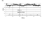
本実施形態においては、このような拍動間隔の急峻な低下及び上昇の抽出によって体幹筋収縮が検出される。ところで、拍動間隔の挙動には、データPで表されるような不規則な変化及び体幹筋収縮発生時の急峻な変化に加えて、呼吸性変動のような規則的すなわち周期的な変化も観察される。例えば、図3に拍動間隔の呼吸性変動を示す。 In the present embodiment, trunk muscle contraction is detected by extraction of such a steep decrease and increase in pulsation interval. By the way, in the behavior of the pulsation interval, in addition to the irregular change represented by the data P and the abrupt change when the trunk muscle contraction occurs, a regular or periodic change such as respiratory change is generated. Is also observed. For example, FIG. 3 shows the respiratory fluctuation of the pulsation interval.
図3において、横軸は時間であり、縦軸は拍動間隔(AAI)あり、データRは拍動間隔(AAI)を示し、データSは体幹筋収縮検出結果を示す。なお、図2の拍動間隔データの被験者(以下、「被験者A」という)と図3の拍動間隔データの被験者(以下、「被験者B」という)は別人である。呼吸性変動による拍動間隔の変化には個人差があるもののその周波数は約0.1〜0.5Hzの範囲であることが知られている。図2及び図3から分かるように、被験者Aの体幹筋収縮は比較的顕著に表れるが、被験者Bの体幹筋収縮は呼吸性変動にうもれて検出されにくい(なお、図3においては、被験者Bは呼吸を行っているのみであり、体幹筋収縮は発生していない)。従って、取得された拍動間隔の変化において、体幹筋収縮に起因する急峻な変化を呼吸性変動に起因する変化から確実に識別することが必要となる。 In FIG. 3, the horizontal axis represents time, the vertical axis represents pulsation interval (AAI), data R represents pulsation interval (AAI), and data S represents trunk muscle contraction detection results. Note that the subject of the pulsation interval data in FIG. 2 (hereinafter referred to as “subject A”) and the subject of the pulsation interval data in FIG. 3 (hereinafter referred to as “subject B”) are different persons. Although there are individual differences in the change in the pulsation interval due to respiratory changes, the frequency is known to be in the range of about 0.1 to 0.5 Hz. As can be seen from FIGS. 2 and 3, the trunk muscle contraction of the subject A appears relatively prominently, but the trunk muscle contraction of the subject B is difficult to be detected due to respiratory variation (in FIG. 3, Subject B is only breathing and no trunk muscle contraction has occurred). Therefore, it is necessary to reliably distinguish a steep change resulting from trunk muscle contraction from a change caused by respiratory changes in the obtained change in pulsation interval.
拍動間隔データ解析ユニット40は、変化成分取得部410、振動成分除去部420、及び変動成分抽出部430を備える。拍動間隔データ解析ユニット40は、拍動間隔データにおいて短時間のうちに発生する、拍動間隔の低下後の増加を抽出するように構成される。
The beat interval
変化成分取得部410は本実施形態においては微分処理部411からなる。微分処理部411は、拍動間隔値が時系列に配列された拍動間隔データについて、所定の拍数を微分間隔として微分する。体幹筋収縮に起因する拍動変動の周波数範囲は0.04〜0.4Hz程度であるため、上記所定の拍数は2〜20拍程度であればよい。例えば、拍動間隔値AAI(i)と拍動間隔値AAI(i+n)(n:2〜20程度)の差分をとり、当該差分を時間で除すことにより微分値とすることができる。ここで、微分間隔となる拍数が小さいと(すなわち、nが小さいと)ノイズ耐性が低くなり、微分間隔となる拍数が大きい(すなわち、nが大きいと)処理速度が低下し、又は複数の体幹筋収縮動作が微分間隔中に含まれる可能性が高くなってしまう。このような事情を考慮して、上記の所定の拍数は3〜7拍であることが好ましい。このように、微分処理部411は拍動間隔データにおける変化成分データとして微分値データを振動成分除去部420に出力する。
The change
振動成分除去部420は、正側ピーク検出部421、正側ピーク保持部422、負側ピーク検出部423、減算部424、及び出力部425を備える。振動成分除去部420は、変化成分取得部410によって微分処理された変化成分データから、拍動間隔データにおける周期的な振動に対応する成分を除去して振動成分除去データを生成する。上述したように、体幹筋収縮に起因する拍動間隔値は短時間のうちに低下した後増加するため、この変動に対応する微分値波形は負のピークの後に正のピークが連続するものとなる。従って、この順序とは逆の順序で発生するピークの連続、すなわち、正のピークの後に負のピークが連続する波形成分を除去する処理により、上記の体幹筋収縮に起因する拍動間隔データの微分値波形が残ることになる。
The vibration
正側ピーク検出部421は上記微分波形における正のピークの有無を判定し、正のピークを検出した場合には正側ピーク保持部422に正のピークに関する正ピーク特徴値を保持する。
The positive
負側ピーク検出部423は、正側ピーク検出部421によって正のピークが検出されてから所定の拍数が経過するまでに負のピークが発生するか否かを検出する。正のピークが検出されてから所定の拍数が経過するまでに負のピークが検出されない場合には、正側ピーク保持部422に保持された正ピーク特徴値は廃棄される。
The
減算部424は、負側ピーク検出部423によって正のピークが検出されてから所定の拍数が経過するまでに負のピークが検出された場合には、負のピークに関する負ピーク特徴値を、正側ピーク保持部422に保持されていた正ピーク特徴値に基づいて減じる処理を行う。例えば、負ピーク特徴値から正ピーク特徴値が減算される。ここで、正ピーク特徴値及び負ピーク特徴値とは、それぞれのピーク値であってもよいし、時間にわたる積分値であってもよい。
When the negative peak is detected by the time the predetermined number of beats has elapsed after the negative
例えば、図4に示すように、微分値波形において、時刻txに正ピーク特徴値xの正のピークXの後に、時刻tyに負ピーク特徴値yの負のピークYがある場合を想定する。時間差ty−txが所定拍数範囲内である場合には、負ピーク特徴値yから正ピーク特徴値xが減算され、時間差ty−txが所定拍数範囲外である場合には、負ピーク特徴値yに対する減算処理は行われない。なお、上記の所定の拍数範囲は、呼吸性変動に相当する拍数範囲(2〜16拍程度)から設定され、好適には1〜8拍程度である。 For example, as shown in FIG. 4, it is assumed that in the differential value waveform, after the positive peak X of the positive peak feature value x at the time tx, there is a negative peak Y of the negative peak feature value y at the time ty. When the time difference ty-tx is within the predetermined beat range, the positive peak feature value x is subtracted from the negative peak feature value y, and when the time difference ty-tx is outside the predetermined beat range, the negative peak feature No subtraction process is performed on the value y. In addition, said predetermined beat number range is set from the beat number range (about 2-16 beats) equivalent to respiratory change, Preferably it is about 1-8 beats.
図5を用いて、より詳細に振動成分除去処理を説明する。図5は、図4と同様に微分値波形を示し、横軸は時間を示す。同図では、時刻順に、正側では正のピークX1〜X4及び負側では負のピークY1〜Y4が例示される。それぞれの発生時刻はtx1〜tx4及びty1〜ty4であり、それぞれのピーク特徴値はx1〜x4及びy1〜y4であるものとする。また、時間差ty1−tx1、ty2−tx2、及びty3−tx3は上記の所定拍数範囲内であり、時間差ty4−tx4は所定拍数範囲外であるものとする。 The vibration component removal process will be described in more detail with reference to FIG. FIG. 5 shows the differential waveform similarly to FIG. 4, and the horizontal axis shows time. In the figure, in order of time, positive peaks X1 to X4 on the positive side and negative peaks Y1 to Y4 on the negative side are illustrated. The occurrence times are tx1 to tx4 and ty1 to ty4, and the respective peak feature values are x1 to x4 and y1 to y4. In addition, the time differences ty1-tx1, ty2-tx2, and ty3-tx3 are within the predetermined beat number range, and the time differences ty4-tx4 are outside the predetermined beat number range.
ここで、正のピークX1の直後の負のピークY1については、ピーク特徴値y1−x1が行われ、ピーク特徴値x1とピーク特徴値y1はほぼ等しいため、負のピークY1のピーク特徴値についての減算結果は実質的にゼロとなる。従って、ピークY1は振動成分として除去されたことになる。正のピークX2の直後の負のピークY2についても同様に、ピーク特徴値y2−x2が行われ、ピーク特徴値x2>ピーク特徴値y2であるため、負のピークY2のピーク特徴値についての減算結果はマイナス(又はゼロとして処理してもよい)となる。従って、ピークY2は振動成分として除去されたことになる。正のピークX3の直後の負のピークY3についてもピーク特徴値y3−x3が行われるが、ピーク特徴値x3<ピーク特徴値y3となるため、負のピークY3のピーク特徴値についての減算結果はゼロとはならない。従って、ピークY3は振動成分としては除去されないことになる。正のピークX4の後の負のピークY4については、上記のように時間差ty4−tx4が所定拍数範囲外であるので減算処理は行われず、すなわち、負のピークY4も振動成分としては除去されない。 Here, for the negative peak Y1 immediately after the positive peak X1, the peak feature value y1-x1 is performed, and the peak feature value x1 and the peak feature value y1 are substantially equal, so the peak feature value of the negative peak Y1 is The subtraction result is substantially zero. Therefore, the peak Y1 is removed as a vibration component. Similarly, for the negative peak Y2 immediately after the positive peak X2, the peak feature value y2-x2 is performed, and since the peak feature value x2> the peak feature value y2, the subtraction for the peak feature value of the negative peak Y2 is performed. The result is negative (or may be treated as zero). Therefore, the peak Y2 is removed as a vibration component. Although the peak feature value y3-x3 is also performed for the negative peak Y3 immediately after the positive peak X3, since the peak feature value x3 <the peak feature value y3, the subtraction result for the peak feature value of the negative peak Y3 is It will not be zero. Therefore, the peak Y3 is not removed as a vibration component. The negative peak Y4 after the positive peak X4 is not subtracted because the time difference ty4-tx4 is outside the predetermined beat number range as described above, that is, the negative peak Y4 is not removed as a vibration component. .
出力部425は、変化成分取得部410の微分処理部411からの微分データ及び減算部424からの減算データを変動成分抽出部430に出力する。出力部425は、必要に応じて、減算部424による減算結果と、減算部424によって減算処理が行われない他のデータとを時間的に整合するようにしてもよい。このように、拍動間隔データ(微分値)から周期的な振動に対応する成分(微分値)を除去した振動除去データが振動成分除去部420から変動成分抽出部430に出力される。
The
変動成分抽出部430は反転部431及び比較部432を備え、振動成分除去部420から供給された振動成分除去データのうち所定の変動成分を抽出し、抽出された変動成分に基づいて体幹筋収縮の発生を特定し、所定の変動成分を与える時刻を体幹筋収縮検出時刻として決定する。
The fluctuation
反転部431は振動成分除去部420からの振動除去データを反転し、反転された振動除去データの正側の値(以下、「反転データ」という)を出力する。これにより、図2に示すデータQが得られる。
The
比較部432は反転データのうち所定の閾値以上となるピークを抽出する。図2のデータQを参照すると、ピークp1〜p6のうち、所定の閾値(本例ではAAI=0.1)以上となるピークp1、p2、p3、p4及びp6が抽出され、閾値未満であるピークp5は抽出されない。なお、図3に示すように、呼吸性振動に上記各処理を施した検出結果であるデータSには、閾値以上となるピークは発生しない。これは、拍動間隔データに呼吸性変動のみが存在する場合には、上記処理の結果として、体幹筋収縮に起因する変動は検出されないことを示している。
The
このように、変動成分抽出部430は、振動除去データの負側のピーク値が所定の閾値以上となるピーク部の発生に基づいて体幹筋収縮を特定し、その発生時刻を体幹筋収縮の検出時刻として出力する。ピーク部の時刻がフィルタ処理等で遅延する場合には、変動成分抽出部430は、その遅延時間を算出し、遅延時間分を補正した時間を体幹筋収縮の検出時刻として出力する。
In this way, the fluctuation
拍動間隔データ解析ユニット40の変動成分抽出部430によって特定された体幹筋収縮検出結果(体幹筋収縮発生の有無、体幹筋収縮検出時刻等)は表示部50等に出力される。表示部50は、例えば、液晶ディスプレイ(LCD)等からなる。なお、取得された拍動データ、拍動間隔データ、体幹筋収縮検出結果は、例えば、上述したRAMなどに蓄積して記憶しておき、計測が終了した後に、パーソナルコンピュータ(PC)等に出力して確認するようにしてもよい。また、体幹筋収縮検出結果はスピーカ55から音声によって出力されるようにしてもよい。スピーカ55からは体幹筋収縮検出時にブザー音、チャイム音、音声ガイド等が出力され得る。またさらに、上記検出結果を、通信部60を介して、例えば、PC、スマートフォン等に送信して表示させる構成とすることもできる。
The trunk muscle contraction detection results (existence of trunk muscle contraction occurrence, trunk muscle contraction detection time, etc.) specified by the fluctuation
次に、図6を参照しつつ、体幹筋収縮検出装置1の動作について説明する。まず、ステップS100では、光電脈波センサ20により検出された光電脈波信号(光電脈波波形)が読み込まれる。
Next, the operation of the trunk muscle
続くステップS102では、ステップS100で読み込まれた光電脈波信号に対してフィルタリング処理が施される。また、光電脈波信号が2階微分されることにより加速度脈波が取得される。次に、ステップS104では、光電脈波信号(加速度脈波信号)のピークが検出される。そして、検出されたすべてのピークについて、ピーク時刻、ピーク振幅等の情報が記憶される。さらに、光電脈波信号(加速度脈波)のピークの遅延時間(ずれ量)が求められるとともに、求められた遅延時間に基づいて光電脈波信号(加速度脈波)のピークが補正される。なお、各ピークの補正方法は上述した通りであるので、ここでは詳細な説明を省略する。ステップS106では、補正後の光電脈波のピークを集計して拍動間隔データを生成する。ここでは、拍動間隔取得ユニット30の拍動間隔データ生成部330が拍動間隔データを生成し、拍動間隔データ解析ユニット40に出力する。
In subsequent step S102, filtering processing is performed on the photoelectric pulse wave signal read in step S100. Further, the acceleration pulse wave is obtained by second-order differentiation of the photoelectric pulse wave signal. Next, in step S104, the peak of the photoelectric pulse wave signal (acceleration pulse wave signal) is detected. Information such as peak time and peak amplitude is stored for all detected peaks. Further, the peak delay time (shift amount) of the photoelectric pulse wave signal (acceleration pulse wave) is obtained, and the peak of the photoelectric pulse wave signal (acceleration pulse wave) is corrected based on the obtained delay time. Since the correction method for each peak is as described above, detailed description is omitted here. In step S106, pulsation interval data is generated by compiling the corrected photoelectric pulse wave peaks. Here, the pulsation interval
ステップ110では、変化成分取得部410の微分処理部411が、拍動間隔値が時系列に配列された拍動間隔データについて、2〜20拍程度の拍数を微分間隔として微分する。例えば、拍動間隔値AAI(i)と拍動間隔値AAI(i+n)(n:2〜20程度、好ましくは3〜7)の差分をとることにより当該差分を微分値とすることができる。そして、変化成分取得部410は変化成分データとしての微分波形データを振動成分除去部420に出力する。
In
続くステップS112〜S126では、振動成分除去部420が、変化成分取得部410bによって微分処理された変化成分データから、拍動間隔データにおける周期的な振動に対応する成分を除去して振動成分除去データを生成する。上述したように、振動成分除去部420は、上記変化成分データから、正のピークの後に負のピークが連続する波形成分を除去する処理を行う。これらのステップは、正側ピーク検出部421、正側ピーク保持部422、負側ピーク検出部423、減算部424、出力部425、及びCPUによって行われる。
In subsequent steps S112 to S126, the vibration
ステップS112では、正側ピーク検出部421が、変化成分データにおける正のピークの有無を判定する。正のピークが検出された場合(ステップS112、Yes)、ステップS114において、正側ピーク保持部422が、正ピーク特徴値を保持する。ステップS114の後、又は正のピークが検出されなかった場合(ステップS112、No)、処理はステップS116に進む。
In step S112, the positive
ステップS116では、正側ピーク保持部422に正ピーク特徴値が保持されているか否かが判別される。正側ピーク保持部422に正ピーク特徴値が保持されている場合(ステップS116、Yes)、処理はステップS118に進み、それ以外の場合には処理はステップS126に進む。
In step S116, it is determined whether or not the positive peak feature value is held in the positive
ステップS118では、負側ピーク検出部423が、正のピークが検出されてからの経過拍数が所定拍数範囲内であるか否かを判定する。経過拍数が所定拍数範囲内である場合(ステップS118、Yes)、処理はステップS120に進む。一方、経過拍数が所定拍数範囲外となった場合(ステップS118、No)、ステップS122において、正側ピーク保持部422に保持されていた正ピーク特徴値が廃棄される。
In step S118, the
ステップS120では、負側ピーク検出部423が、変化成分データにおける負のピークの有無を判定する。負のピークが検出された場合(ステップS120、Yes)、処理はステップS124に進む。負のピークが検出されなかった場合(ステップS120、No)、処理はステップS126に進む。
In step S120, the negative
ステップS124では、減算部424が、負ピーク特徴値を、正側ピーク保持部422に保持されていた正ピーク特徴値に応じて減じる処理を行う。例えば、負ピーク特徴値から正ピーク特徴値が減算される。これにより、正のピークから所定拍数範囲内に現れる負のピークの成分が変化成分データ(すなわち、微分波形データ)から除去される。
In step S <b> 124, the
ステップS126では、出力部425が、ステップS112において微分処理されたデータ及びステップS124において減算処理されたデータを出力する。これにより、ステップS124における減算結果とステップS124を通過しない他のデータとが必要に応じて時間的に整合された状態で振動成分除去データが変動成分抽出部430に出力される。
In step S126, the
ステップS128〜S130では、変動成分抽出部430が、振動成分除去部420から供給された振動成分除去データのうち所定の変動成分を抽出し、抽出された変動成分に基づいて体幹筋収縮の発生を特定する。
In steps S128 to S130, the fluctuation
ステップS128では、反転部431が、振動成分除去部420からの振動成分除去データを反転し、反転された振動成分除去データの正側の値である反転データを出力する。
In step S128, the
ステップS130では、比較部432が、反転データを所定の閾値と比較し、閾値以上となる反転データをピークとして抽出して体幹筋収縮の発生を特定し、所定の変動成分を与える時刻を体幹筋収縮検出時刻として特定する。
In step S130, the
ステップS132では、表示部50等が、ステップS130で特定された体幹筋収縮検出結果(体幹筋収縮の発生の有無、体幹筋収縮検出時刻等)を表示するなどして出力する。
In step S132, the
なお、本実施形態においては、周期的振動成分を除去する構成として、正のピークの直後の負のピークを実質的に消去する構成を採用したが、呼吸性変動の拍数に相当する振動成分を適応的に除去する適応フィルタが採用されてもよい。また、本実施形態においては、変化成分取得部410による微分処理の後に、振動成分除去部420による振動成分除去処理を行う構成を示したが、振動成分除去処理の後に微分処理を行う構成としてもよい。また、本実施形態においては、拍動センサ(光電脈波センサ)20、拍動間隔データ生成ユニット30、拍動間隔データ解析ユニット40等が一体化されたものとして説明を行ったが、拍動間隔データ解析ユニット40は拍動間隔データ生成ユニット30と別体のものであってもよい。この場合、拍動間隔データ生成ユニット30からの拍動間隔データは有線通信又は無線通信により拍動間隔データ解析ユニット40に送信される。
In the present embodiment, as a configuration for removing the periodic vibration component, a configuration in which the negative peak immediately after the positive peak is substantially eliminated is employed. However, the vibration component corresponding to the number of beats of respiratory change is used. An adaptive filter may be employed that adaptively removes. In the present embodiment, the configuration in which the vibration component removal processing by the vibration
以上のように、本実施形態の構成によると、拍動間隔データから、呼吸等に起因する周期的振動成分が除去されるので、体幹筋収縮に起因する拍動変動を確実に抽出することができる。また、体幹筋収縮が発生してから検出結果が出力されるまでの時間は実質的には微分処理のための数拍程度しか要さないので、準リアルタイム的に適時に検出結果を得ることが可能となる。 As described above, according to the configuration of the present embodiment, since the periodic vibration component caused by breathing or the like is removed from the beat interval data, the beat fluctuation caused by the trunk muscle contraction can be reliably extracted. Can do. In addition, the time from when the trunk muscle contraction occurs until the detection result is output requires substantially only a few beats for differential processing. Is possible.
(第2実施形態)
図7を用いて、第2実施形態に係る体幹筋収縮検出装置2の構成について説明する。図7は、体幹筋収縮検出装置2の構成を示すブロック図である。なお、第1実施形態の体幹筋収縮検出装置1と同様の構成要素には同様の符号を付しその説明を省略する。体幹筋収縮検出装置2は拍動間隔データ解析ユニット40bを備え、拍動間隔データ解析ユニット40bは、変化成分取得部410b、振動成分除去部420b及び変動成分抽出部430を備える。すなわち、変化成分取得部410b及び振動成分除去部420bが第1実施形態の変化成分取得部410及び振動成分除去部420と異なる。変化成分取得部410bは補間処理部412及び微分処理部413を備える。(Second Embodiment)
The configuration of the trunk muscle
補間処理部412は、拍動間隔が時系列順に並べられた拍動間隔データの補間処理を行う。ここで、補間処理はスプライン補間等であればよく、これにより拍動間隔データが一定の時間間隔(例えば、0.01秒間隔)で切り出されることができる。この補間処理によってその後の処理において、データを周波数の関数として処理することができる。
The
微分処理部413は、補間された拍動間隔データを所定の時間間隔で微分する。ここで、体幹筋の収縮によって発生する拍動変動の周波数範囲は0.04〜0.4Hz程度であるため、微分のための時間間隔は1.25〜12.5秒程度が好適である。
The
振動成分除去部420bは適応フィルタ427からなる。適応フィルタ427は、変化成分取得部410bからの波形データの周期的振動を除去するように構成される。除去対象となる周期的振動は呼吸性変動に相当する周波数0.1〜0.5Hz程度の範囲であるので、適応フィルタ427はこの範囲の周波数成分を除去するように、最適化アルゴリズムに従ってその伝達関数を自己適応させる。これにより、上記周波数によって周期的に変動することのない拍動成分が振動成分除去データとして抽出される。なお、本実施形態では振動成分除去部420bとして適応フィルタ427を用いているが、除去すべき周期的振動の成分の周波数が予め分かっている場合(例えば、特定の被験者専用に拍動間隔データ解析ユニット40bが作成される場合等)はカットオフ周波数範囲が比較的狭い周波数フィルタ等が採用されてもよい。
The vibration
このように、振動成分除去部420bからの振動成分除去データが変動成分抽出部430に入力され、変動成分抽出部430では第1実施形態と同様のデータ抽出処理が行われる。変動成分抽出部430によって特定された体幹筋収縮検出結果(体幹筋収縮発生の有無、体幹筋収縮検出時刻等)は表示部50又はスピーカ55に出力される。また、上記検出結果を、通信部60を介して、例えば、PC、スマートフォン等に送信して表示させる構成とすることもできる。
As described above, the vibration component removal data from the vibration
次に、図8を参照しつつ、本実施形態の体幹筋収縮検出装置2の動作について説明する。ステップS102〜S106の処理は図6に示す第1実施形態のステップS102〜S106の処理と同様であるので説明を省略する。
Next, the operation of the trunk muscle
ステップS106の後のステップS210では、補間処理部412が、拍動間隔が時系列順に並べられた拍動間隔データに、スプライン補間等の補間処理を適用し、拍動間隔データを、例えば、0.01秒間隔程度の一定間隔で切り出す。
In step S210 after step S106, the
ステップS212では、微分処理部413が、補間された拍動間隔データを1.25〜12.5秒程度の時間間隔で微分し、これを変化成分データとして振動成分除去部420bに出力する。
In step S212, the
ステップS214では、適応フィルタ427が、変化成分取得部410bから入力された変化成分データにおける、例えば0.1〜0.5Hz程度の周期的振動を除去し、この上記周波数によって周期的に変動しない拍動成分を振動成分除去データとして抽出する。
In step S214, the
ステップS214の後のステップS228〜S232は第1実施形態のステップS128〜S132と同様である。すなわち、ステップS228で反転部431が振動成分除去データを反転して反転データを出力し、ステップS230では、比較部432が、反転データを所定の閾値と比較し、閾値以上となる反転データをピークとして抽出して体幹筋収縮の発生を特定し、所定の変動成分を与える時刻を体幹筋収縮検出時刻として特定する。そして、ステップS232では、表示部50等が、ステップS230で特定された体幹筋収縮検出結果(体幹筋収縮発生の有無、体幹筋収縮検出時刻等)を表示するなどして出力する。
Steps S228 to S232 after step S214 are the same as steps S128 to S132 of the first embodiment. That is, in step S228, the
以上のように、本実施形態の構成によると、補間処理によって拍動間隔データを周波数軸上で処理することが可能となり、振動成分除去のための処理の設計自由度が向上する。また、例えば2〜3拍数程度に対応する短い振動周期の拍動間隔データについて、補間処理が施されることにより、その振動特性が捕捉され易くなるので、振動成分除去の精度を向上することができる。 As described above, according to the configuration of the present embodiment, it is possible to process pulsation interval data on the frequency axis by interpolation processing, and the degree of freedom in design of processing for removing vibration components is improved. Further, for example, by performing interpolation processing on the pulse interval data having a short vibration period corresponding to about 2 to 3 beats, the vibration characteristics can be easily captured, thereby improving the accuracy of vibration component removal. Can do.
(第3実施形態)
図9を用いて、第3実施形態に係る体幹筋収縮検出装置3の構成について説明する。図9は、体幹筋収縮検出装置3の構成を示すブロック図である。なお、第2実施形態の体幹筋収縮検出装置2と同様の構成要素には同様の符号を付しその説明を省略する。体幹筋収縮検出装置3は拍動間隔データ解析ユニット40cを備え、拍動間隔データ解析ユニット40cは、変化成分取得部410c、振動成分除去部420b及び変動成分抽出部430cを備える。すなわち、変化成分取得部410c及び変動成分抽出部430cの構成が第2実施形態の変化成分取得部410b及び変動成分抽出部430と異なる。(Third embodiment)
The configuration of the trunk muscle
変化成分取得部410cは補間処理部412を備える。補間処理部412は、拍動間隔が時系列順に並べられた拍動間隔データの補間処理を行う。ここで、補間処理はスプライン補間等であればよく、これにより拍動間隔データが一定の時間間隔(例えば、0.01秒間隔)で切り出されることができる。この補間処理されたデータは周波数の関数として処理される。
The change
振動成分除去部420bは第2実施形態と同様に適応フィルタ427からなる。すなわち、適応フィルタ427は、変化成分取得部410cからの波形データの周期的振動(0.1〜0.5Hz)を除去して振動成分除去データを生成する。振動成分除去部420bからの振動成分除去データは変動成分抽出部430cに入力される。
The vibration
変動成分抽出部430cは基準波形記憶部433、相関係数算出部434、相関度決定部435及び判定部436を備える。
The fluctuation
基準波形記憶部433は、検出対象となる拍動変動のモデルとなる基準波形を記憶する。この基準波形として、体幹筋動作時に発生する拍動変動をモデル化したものが使用され、単純なモデルとしては、拍動数変動を矩形波、三角波等で近似したものを使用することができる。
The reference
相関係数算出部434は、振動成分除去データと基準波形記憶部433に記憶される基準波形との相関係数を算出する。相関度決定部435は、相関係数算出部434によって算出された相関係数が所定値を超えた場合に検出信号及び相関度を出力する。
The correlation
判定部436は、検出信号が入力された場合に相関度に従って変動成分を抽出して体幹筋収縮の発生を特定し、変動成分を与える時刻を体幹筋収縮検出時刻として特定する。このように、変動成分抽出部430によって特定された体幹筋収縮検出結果(体幹筋収縮発生の有無、体幹筋収縮検出時刻等)は表示部50又はスピーカ55に出力される。また、上記検出結果を、通信部60を介して、例えば、PC、スマートフォン等に送信して表示させる構成とすることもできる。
When the detection signal is input, the
次に、図10を参照しつつ、本実施形態の体幹筋収縮検出装置3の動作について説明する。ステップS102〜S106の処理は図6に示す第1実施形態のステップS102〜S106の処理と同様であるので説明を省略する。
Next, the operation of the trunk muscle
ステップS106の後のステップS310では、補間処理部412が、拍動間隔が時系列順に並べられた拍動間隔データに、スプライン補間等の補間処理を適用し、拍動間隔データを、例えば、0.01秒間隔程度の一定間隔で切り出す。
In step S310 after step S106, the
ステップS312では、適応フィルタ427が、変化成分取得部410cから入力された変化成分データにおける、例えば0.1〜0.5Hz程度の周期的振動を除去し、この上記周波数によって周期的に変動しない拍動成分を振動成分除去データとして抽出する。
In step S312, the
ステップS314では、基準波形記憶部433から、検出対象となる拍動変動のモデルとなる基準波形が読み出される。
In step S314, a reference waveform that is a model of pulsation fluctuation to be detected is read from the reference
ステップS316では、相関係数算出部434が、振動成分除去データと基準波形との相関係数を算出し、ステップS318では、相関度決定部435が、ステップS316において算出された相関係数が所定値を超えた場合に検出信号及び相関度を出力する。
In step S316, the correlation
ステップS320では、判定部436が、検出信号が入力された場合に相関度に基づいて変動成分を抽出して体幹筋収縮の発生を特定し、変動成分を与える時刻を体幹筋収縮検出時刻として特定する。そして、ステップS332では、表示部50等が、ステップS320で特定された体幹筋収縮検出結果(体幹筋収縮発生の有無、体幹筋収縮検出時刻等)を表示するなどして出力する。
In step S320, when the detection signal is input, the
なお、本実施形態においては、振動成分除去処理に適応フィルタを用いる構成を示したが、ウェーブレット変換を行い、その変換データから周期振動成分を除去し、周期振動成分除去後のデータから体幹筋収縮に起因する変動成分を抽出する構成としてもよい。また、変動成分抽出処理として、振動成分除去データと基準波形との相関係数を算出する構成を示したが、所定時間間隔で微分処理を行い、負のピークが所定の閾値以上であるピークを抽出し、このピークの時刻を体幹筋収縮検出時刻として出力する構成としてもよい。 In the present embodiment, the configuration using an adaptive filter for vibration component removal processing is shown. However, wavelet transformation is performed, the periodic vibration component is removed from the converted data, and the trunk muscle is obtained from the data after the periodic vibration component removal. It is good also as a structure which extracts the fluctuation | variation component resulting from shrinkage | contraction. In addition, as the fluctuation component extraction processing, the configuration in which the correlation coefficient between the vibration component removal data and the reference waveform is calculated is shown. However, the differential processing is performed at a predetermined time interval, and a peak whose negative peak is equal to or greater than a predetermined threshold is displayed. It is good also as a structure which extracts and outputs the time of this peak as trunk muscle contraction detection time.
以上のように、本実施形態の構成においても、第2実施形態と同様に、拍動間隔データを周波数軸上で処理することが可能となり、振動成分除去のための処理の設計自由度が向上する。また、例えば2〜3拍数程度に対応する短い振動周期の拍動間隔データについて、補間処理が施されることにより、その振動特性が捕捉され易くなるので、振動成分除去の精度を向上することができる。 As described above, also in the configuration of the present embodiment, it is possible to process pulsation interval data on the frequency axis as in the second embodiment, and the degree of freedom in design of processing for removing vibration components is improved. To do. Further, for example, by performing interpolation processing on the pulse interval data having a short vibration period corresponding to about 2 to 3 beats, the vibration characteristics can be easily captured, thereby improving the accuracy of vibration component removal. Can do.
1、2、3 体幹筋収縮検出装置
20 拍動センサ
30 拍動間隔データ生成ユニット
40、40b、40c 拍動間隔データ解析ユニット
410、410b、410c 変化成分取得部
411、413 微分処理部
412 補間処理部
420、420b 振動成分除去部
421 正側ピーク検出部
422 正側ピーク保持部
423 負側ピーク検出部
424 減算部
425 バッファ
430、430c 変動成分抽出部
431 反転部
432 比較部
433 基準波形記憶部
434 相関係数算出部
435 相関度決定部
436 判定部
1, 2, 3 Trunk muscle
Claims (5)
前記変化成分データから、前記拍動間隔データにおける周期的な振動に対応する振動成分を除去して振動成分除去データを生成する振動成分除去部と、
前記振動成分除去データのうち、体幹筋収縮が発生していないときと比べて拍動間隔が急峻に低下してから増加する変動成分を抽出し、抽出した該変動成分に基づいて体幹筋収縮の発生を特定する変動成分抽出部と
を備えることを特徴とする体幹筋収縮検出装置。 A change component acquisition unit that acquires change component data representing a change component of a beat interval in the beat interval data;
A vibration component removing unit that generates vibration component removal data by removing vibration components corresponding to periodic vibrations in the beat interval data from the change component data;
Wherein among the vibration components removed data, the body on the basis of the displacement movement components extracted fluctuation component extracted for beating gap than when the trunk muscle contraction does not occur to increase the decreased abruptly A trunk muscle contraction detection apparatus comprising: a fluctuation component extraction unit that identifies occurrence of trunk muscle contraction.
The trunk muscle contraction detecting device according to any one of claims 1 to 4, further comprising pulsation interval data generation means for detecting the pulsation of a subject and generating the pulsation interval data.
Applications Claiming Priority (3)
| Application Number | Priority Date | Filing Date | Title |
|---|---|---|---|
| JP2013163951 | 2013-08-07 | ||
| JP2013163951 | 2013-08-07 | ||
| PCT/JP2014/068866 WO2015019808A1 (en) | 2013-08-07 | 2014-07-16 | Trunk muscle contraction-detecting device |
Publications (2)
| Publication Number | Publication Date |
|---|---|
| JPWO2015019808A1 JPWO2015019808A1 (en) | 2017-03-02 |
| JP6187589B2 true JP6187589B2 (en) | 2017-08-30 |
Family
ID=52461147
Family Applications (1)
| Application Number | Title | Priority Date | Filing Date |
|---|---|---|---|
| JP2015530774A Active JP6187589B2 (en) | 2013-08-07 | 2014-07-16 | Trunk muscle contraction detector |
Country Status (3)
| Country | Link |
|---|---|
| US (1) | US20160151000A1 (en) |
| JP (1) | JP6187589B2 (en) |
| WO (1) | WO2015019808A1 (en) |
Families Citing this family (5)
| Publication number | Priority date | Publication date | Assignee | Title |
|---|---|---|---|---|
| US10406434B1 (en) * | 2012-12-19 | 2019-09-10 | Alert Core, Inc. | Video game controller using core muscles and other applications |
| WO2016024476A1 (en) * | 2014-08-15 | 2016-02-18 | 株式会社村田製作所 | Bio-information sensor |
| CN107485854B (en) * | 2017-08-03 | 2022-03-01 | 惠州Tcl移动通信有限公司 | Game paddle control method, storage medium and game paddle |
| JP2019033868A (en) * | 2017-08-14 | 2019-03-07 | ソニー株式会社 | Communication device and communication method |
| JP6922790B2 (en) * | 2018-03-07 | 2021-08-18 | 日本電信電話株式会社 | Fatigue estimation device and program |
Family Cites Families (5)
| Publication number | Priority date | Publication date | Assignee | Title |
|---|---|---|---|---|
| GB2453099A (en) * | 2007-07-19 | 2009-04-01 | Univ Sussex | Sensor system with tunable narrow band filter. |
| JP5038222B2 (en) * | 2008-04-21 | 2012-10-03 | 株式会社デンソー | Biological state estimation device, program, and recording medium |
| US8574162B2 (en) * | 2008-06-30 | 2013-11-05 | Nellcor Puritan Bennett Ireland | Systems and methods for detecting pulses |
| US8321017B2 (en) * | 2009-07-08 | 2012-11-27 | Pacesetter, Inc. | Electromechanical delay (EMD) monitoring devices, systems and methods |
| EP2524647A1 (en) * | 2011-05-18 | 2012-11-21 | Alain Gilles Muzet | System and method for determining sleep stages of a person |
-
2014
- 2014-07-16 WO PCT/JP2014/068866 patent/WO2015019808A1/en active Application Filing
- 2014-07-16 JP JP2015530774A patent/JP6187589B2/en active Active
-
2016
- 2016-02-05 US US15/016,329 patent/US20160151000A1/en not_active Abandoned
Also Published As
| Publication number | Publication date |
|---|---|
| JPWO2015019808A1 (en) | 2017-03-02 |
| US20160151000A1 (en) | 2016-06-02 |
| WO2015019808A1 (en) | 2015-02-12 |
Similar Documents
| Publication | Publication Date | Title |
|---|---|---|
| JP6187589B2 (en) | Trunk muscle contraction detector | |
| JP6126220B2 (en) | Biological state estimation device | |
| TWI538660B (en) | Heart rate detection module, and detection and denoising method thereof | |
| JP5060186B2 (en) | Pulse wave processing apparatus and method | |
| JP6090424B2 (en) | Pulse wave propagation time measurement device | |
| US8758258B2 (en) | Beat detection device and beat detection method | |
| JP6211679B2 (en) | Heart rate detector | |
| KR20130065714A (en) | Pulse period computation device and bio-sensor provided with same | |
| JP6115330B2 (en) | Biological information measuring device and biological information measuring method | |
| US9962120B2 (en) | Sleep state management device, sleep state management method, and sleep state management program | |
| JP2007007075A (en) | Blood pressure measuring apparatus | |
| WO2007032226A1 (en) | Heart rate meter and method for removing noise of heart beat waveform | |
| KR102301740B1 (en) | Apparatus and Method for Removal of Noises in Physiological Measurements | |
| KR20180086546A (en) | A ear headset device for stress measurement and stress measurement method using the same | |
| JP2001198094A (en) | Pulse rate detector | |
| JPWO2011048729A1 (en) | Pulse wave detection device and pulse wave detection method | |
| JP6003493B2 (en) | Noise detection device, noise detection method, and noise detection program | |
| CN110292372B (en) | Detection device | |
| JP5041155B2 (en) | Blood pressure measurement device | |
| WO2018055969A1 (en) | Vital sign processing device, vital sign processing method, and information processing device | |
| JP5582051B2 (en) | Pulse wave measuring device and program | |
| JP2001204714A (en) | Mental stress judging device | |
| JP2014132934A (en) | Measuring apparatus and measuring method | |
| JP5998516B2 (en) | Pulsation detection device, electronic device and program | |
| JP2011087838A5 (en) |
Legal Events
| Date | Code | Title | Description |
|---|---|---|---|
| A131 | Notification of reasons for refusal |
Free format text: JAPANESE INTERMEDIATE CODE: A131 Effective date: 20161206 |
|
| A521 | Request for written amendment filed |
Free format text: JAPANESE INTERMEDIATE CODE: A523 Effective date: 20170126 |
|
| TRDD | Decision of grant or rejection written | ||
| A01 | Written decision to grant a patent or to grant a registration (utility model) |
Free format text: JAPANESE INTERMEDIATE CODE: A01 Effective date: 20170704 |
|
| A61 | First payment of annual fees (during grant procedure) |
Free format text: JAPANESE INTERMEDIATE CODE: A61 Effective date: 20170717 |
|
| R150 | Certificate of patent or registration of utility model |
Ref document number: 6187589 Country of ref document: JP Free format text: JAPANESE INTERMEDIATE CODE: R150 |