JP6186899B2 - Image forming apparatus - Google Patents
Image forming apparatus Download PDFInfo
- Publication number
- JP6186899B2 JP6186899B2 JP2013117475A JP2013117475A JP6186899B2 JP 6186899 B2 JP6186899 B2 JP 6186899B2 JP 2013117475 A JP2013117475 A JP 2013117475A JP 2013117475 A JP2013117475 A JP 2013117475A JP 6186899 B2 JP6186899 B2 JP 6186899B2
- Authority
- JP
- Japan
- Prior art keywords
- belt
- disposed
- moving member
- moving
- transport
- Prior art date
- Legal status (The legal status is an assumption and is not a legal conclusion. Google has not performed a legal analysis and makes no representation as to the accuracy of the status listed.)
- Active
Links
Images


Landscapes
- Dry Development In Electrophotography (AREA)
- Electrophotography Configuration And Component (AREA)
- Electrostatic Charge, Transfer And Separation In Electrography (AREA)
Description
本発明は、電子写真方式が採用される画像形成装置に関する。 The present invention relates to an image forming apparatus employing an electrophotographic system.
電子写真方式が採用される画像形成装置として、ブラック、イエロー、マゼンタ、シアンの各色のトナーに対応して複数の感光ドラムを備えるタンデム型のカラープリンタが知られている。 As an image forming apparatus employing an electrophotographic system, a tandem type color printer having a plurality of photosensitive drums corresponding to toners of black, yellow, magenta, and cyan is known.
このようなカラープリンタとして、各色に対応するプロセスカートリッジを支持する像形成ユニットに、廃トナーを収容する廃トナー収容箱が設けられ、シート搬送ベルトを備えるベルトユニットに、シート搬送ベルトをクリーニングするベルトクリーニング装置と、ベルトクリーニング装置によって回収された廃トナーを廃トナー収容箱へ搬送するベルト廃トナー搬送管とが設けられた画像形成装置が提案されている(たとえば、下記特許文献1参照。)。
As such a color printer, a waste toner storage box that stores waste toner is provided in an image forming unit that supports a process cartridge corresponding to each color, and a belt unit that includes a sheet transport belt and that cleans the sheet transport belt There has been proposed an image forming apparatus provided with a cleaning device and a belt waste toner transport pipe for transporting waste toner collected by the belt cleaning device to a waste toner storage box (see, for example,
しかるに、上記した特許文献1に記載のカラープリンタでは、ベルト廃トナー搬送管が画像形成装置本体のハウジングに固定されており、像形成ユニットに対してベルト廃トナー搬送管を連結した後には、像形成ユニットを移動させることが困難である。
However, in the color printer described in
そのため、像形成ユニットを画像形成装置本体内に装着するときに、ベルトユニットに対するプロセスカートリッジの位置決めと、像形成ユニットに対するベルト廃トナー搬送管の連結とを同時に実施する必要があり、プロセスカートリッジをベルトユニットに対して位置決めすることが困難である。 Therefore, when the image forming unit is mounted in the image forming apparatus main body, it is necessary to simultaneously perform the positioning of the process cartridge with respect to the belt unit and the connection of the belt waste toner transport pipe with respect to the image forming unit. It is difficult to position with respect to the unit.
そこで、本発明の目的は、複数の感光体をベルトユニットに対して容易に位置決めすることができる画像形成装置を提供することにある。 SUMMARY OF THE INVENTION Accordingly, an object of the present invention is to provide an image forming apparatus capable of easily positioning a plurality of photosensitive members with respect to a belt unit.
(1)上記した目的を達成するために、本発明の画像形成装置は、装置本体と、感光体を有する複数のプロセスカートリッジと、複数のプロセスカートリッジを支持するように構成される移動部材と、ベルトユニットと、廃トナー収容部材と、搬送部材とを備える。移動部材は、装置本体内に配置される内側位置と、装置本体外に配置される外側位置との間を移動するように構成される。ベルトユニットは、ベルトと、ベルトに残留した残留トナーをクリーニングするように構成されるクリーニング部材とを有する。廃トナー収容部材は、移動部材に支持され、クリーニング部材によってクリーニングされた残留トナーを収容するように構成される。搬送部材は、クリーニング部材によってクリーニングされた残留トナーを廃トナー収容部材に搬送するように構成される。 (1) In order to achieve the above-described object, an image forming apparatus of the present invention includes an apparatus main body, a plurality of process cartridges having a photoreceptor, and a moving member configured to support the plurality of process cartridges; A belt unit, a waste toner containing member, and a conveying member are provided. The moving member is configured to move between an inner position arranged in the apparatus main body and an outer position arranged outside the apparatus main body. The belt unit includes a belt and a cleaning member configured to clean residual toner remaining on the belt. The waste toner storage member is supported by the moving member and configured to store the residual toner cleaned by the cleaning member. The conveying member is configured to convey the residual toner cleaned by the cleaning member to the waste toner containing member.
複数の感光体は、移動部材が複数のプロセスカートリッジを支持した状態で、移動部材が内側位置に配置されているときに、ベルトに接触される接触位置と、ベルトから離間される離間位置とに移動するように構成される。 When the moving member is arranged at the inner position with the moving member supporting the plurality of process cartridges, the plurality of photosensitive members are in a contact position where the moving member is in contact with the belt and a separated position where the moving member is separated from the belt. Configured to move.
このような構成によれば、移動部材を内側位置に配置した後に、複数の感光体をベルトに接触させることができる。 According to such a configuration, a plurality of photoconductors can be brought into contact with the belt after the moving member is disposed at the inner position.
そのため、移動部材の移動とは別の動作で、複数の感光体をベルトに対して位置決めすることができる。 Therefore, the plurality of photosensitive members can be positioned with respect to the belt by an operation different from the movement of the moving member.
その結果、複数の感光体をベルトユニットに対して容易に位置決めすることができる。
(2)また、移動部材は、内側位置から外側位置へ、第1方向に移動するように構成されてもよい。複数の感光体は、接触位置から離間位置へ、第1方向と交差する第2方向に移動するように構成されてもよい。
As a result, the plurality of photoconductors can be easily positioned with respect to the belt unit.
(2) Further, the moving member may be configured to move in the first direction from the inner position to the outer position. The plurality of photoconductors may be configured to move from a contact position to a separated position in a second direction that intersects the first direction.
このような構成によれば、移動部材が内側位置から外側位置へ移動する第1方向と、複数の感光体がベルトから離間する第2方向とが異なる場合であっても、複数の感光体をベルトユニットに対して容易に位置決めすることができる。
(3)また、搬送部材は、第1搬送部材と、第1搬送部材に対して分離可能に連結されるように構成される第2搬送部材とを有してもよい。ベルトユニットは、第1搬送部材を有してもよい。移動部材は、前記第2搬送部材を有してもよい。
According to such a configuration, even when the first direction in which the moving member moves from the inner position to the outer position and the second direction in which the plurality of photosensitive members are separated from the belt are different, the plurality of photosensitive members are arranged. It can be easily positioned with respect to the belt unit.
(3) Moreover, a conveyance member may have a 1st conveyance member and a 2nd conveyance member comprised so that it might isolate | separate with respect to a 1st conveyance member. The belt unit may have a first conveying member. The moving member may have the second transport member.
このような構成によれば、移動部材を内側位置から外側位置へ移動させる動作を利用して、第1搬送部材と第2搬送部材とを分離し、クリーニング部材から廃トナー収容部材への残留トナーの搬送を遮断することができる。
(4)また、第2搬送部材は、移動部材が内側位置に配置されている状態で、第1方向および第2方向と交差する第3方向において、ベルトユニットに隣接配置されている。
According to such a configuration, the operation of moving the moving member from the inner position to the outer position is used to separate the first conveying member and the second conveying member, and the residual toner from the cleaning member to the waste toner containing member. Can be cut off.
(4) Further, the second conveying member is disposed adjacent to the belt unit in the third direction intersecting the first direction and the second direction in a state where the moving member is disposed at the inner position.
このような構成によれば、第3方向、すなわち、移動部材が内側位置から外側位置へ移動する第1方向、および、複数の感光体がベルトから離間する第2方向と交差する方向において、ベルトユニットの隣の空間を利用して、効率よく第2搬送部材を配置することができる。
(5)また、第2搬送部材は、移動部材が内側位置に配置されている状態で、移動部材からベルトユニット側に突出されていてもよい。
According to such a configuration, the belt in the third direction, that is, the first direction in which the moving member moves from the inner position to the outer position, and the second direction in which the plurality of photosensitive members are separated from the belt. The second conveying member can be efficiently arranged using the space next to the unit.
(5) Moreover, the 2nd conveyance member may protrude in the belt unit side from the moving member in the state by which the moving member is arrange | positioned in the inner position.
このような構成によれば、第1搬送部材をベルトユニットから移動部材側へ突出させる必要がないので、移動部材を移動させるときに第1搬送部材が移動部材に干渉することを防止できる。
(6)また、第2搬送部材は、移動部材が内側位置に配置されている状態で、第1方向および第2方向と交差する第3方向に投影したときに、ベルトユニットの投影面内において、第1搬送部材に連結されていてもよい。
According to such a configuration, it is not necessary to cause the first transport member to protrude from the belt unit to the moving member side, so that the first transport member can be prevented from interfering with the moving member when the moving member is moved.
(6) Further, when the second conveying member is projected in the third direction intersecting the first direction and the second direction in a state where the moving member is disposed at the inner position, the second conveying member is within the projection surface of the belt unit. The first conveying member may be connected.
このような構成によれば、第3方向において、ベルトユニットの隣の空間を利用して、第1搬送部材と第2搬送部材とを連結することができる。
(7)また、第1搬送部材は、クリーニング部材によってクリーニングされた残留トナーを、第1方向および第2方向と交差する第3方向に搬送してもよい。
According to such a configuration, in the third direction, the first transport member and the second transport member can be coupled using the space adjacent to the belt unit.
(7) The first conveying member may convey the residual toner cleaned by the cleaning member in a third direction that intersects the first direction and the second direction.
このような構成によれば、残留トナーを、第3方向に集めて、効率よく回収することができる。
(8)また、第1搬送部材は、第1開口と、移動部材が内側位置に配置された状態で第1開口を開放し、移動部材が外側位置に配置された状態で第1開口を閉鎖するように構成される第1シャッタ部材とを有してもよい。また、第2搬送部材は、移動部材が内側位置に配置された状態で第1開口に対向される第2開口と、移動部材が内側位置に配置された状態で第2開口を開放し、移動部材が外側位置に配置された状態で第2開口を閉鎖するように構成される第2シャッタ部材とを有してもよい。この場合、第1シャッタ部材は、第1方向に沿って移動することにより、第1開口を開放または閉鎖し、第2シャッタ部材は、第1方向に沿って移動することにより、第2開口を開放または閉鎖してもよい。
According to such a configuration, the residual toner can be collected in the third direction and efficiently collected.
(8) The first conveying member opens the first opening with the first opening and the moving member disposed at the inner position, and closes the first opening with the moving member disposed at the outer position. You may have the 1st shutter member comprised so that. The second conveying member opens and moves the second opening opposed to the first opening with the moving member disposed at the inner position, and the second opening opened with the moving member disposed at the inner position. You may have a 2nd shutter member comprised so that a 2nd opening may be closed with the member arrange | positioned in an outer position. In this case, the first shutter member moves along the first direction to open or close the first opening, and the second shutter member moves along the first direction to move the second opening. It may be open or closed.
このような構成によれば、移動部材を外側位置に配置したときに、第1搬送部材の第1開口を第1シャッタ部材で閉鎖するとともに、第2搬送部材の第2開口を第2シャッタ部材で閉鎖することができる。 According to such a configuration, when the moving member is disposed at the outer position, the first opening of the first conveying member is closed by the first shutter member, and the second opening of the second conveying member is closed by the second shutter member. It can be closed with.
そのため、移動部材を外側位置に配置したときに、クリーニング部材から廃トナー収容部材への残留トナーの搬送を確実に遮断することができ、また、第1開口や第2開口からの残留トナーの漏れを確実に防止することができる。
(9)また、移動部材は、内側位置において、複数の感光体の移動を許容するように、複数の感光体を支持していてもよい。
Therefore, when the moving member is disposed at the outer position, the transfer of the residual toner from the cleaning member to the waste toner containing member can be reliably blocked, and the residual toner leaks from the first opening and the second opening. Can be reliably prevented.
(9) The moving member may support a plurality of photoconductors so as to allow movement of the plurality of photoconductors at the inner position.
このような構成によれば、移動部材が内側位置に配置されているときに、確実に、複数の感光体を移動させることができる。 According to such a configuration, it is possible to reliably move the plurality of photoconductors when the moving member is disposed at the inner position.
本発明の画像形成装置によれば、複数の感光体をベルトユニットに対して容易に位置決めすることができる。 According to the image forming apparatus of the present invention, a plurality of photoconductors can be easily positioned with respect to the belt unit.
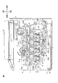
1.プリンタの全体構成
図1に示すように、画像形成装置の一例としてのプリンタ1は、横置きタイプの中間転写型カラープリンタである。
1. Overall Configuration of Printer As shown in FIG. 1, a
なお、以下の説明において、プリンタ1の方向に言及するときには、プリンタ1を水平に載置した状態を上下の基準とする。すなわち、図1の紙面上側が上側であり、紙面下側が下側である。また、図1の紙面左側が前側であり、図1の紙面右側が後側である。また、プリンタ1を前側から見たときを左右の基準とする。すなわち、図1の紙面手前側が右側であり、紙面奥側が左側である。なお、前側は、第1方向の一例であり、上側は、第2方向の一例であり、左側は、第3方向の一例である。
In the following description, when referring to the direction of the
プリンタ1は、装置本体の一例としての本体ケーシング2内において、プロセスユニット4と、スキャナユニット3と、転写ユニット5と、定着ユニット6とを備えている。また、プリンタ1は、本体ケーシング2の上側において、画像読取ユニット10を備えている。
The
本体ケーシング2は、側面視略矩形のボックス形状に形成されている。本体ケーシング2の前端部には、本体開口部7が形成されている。また、本体ケーシング2の前端部には、フロントカバー8が、その下端部を支点として、本体開口部7を閉鎖する閉位置(図1参照)と、本体開口部7を開放する開位置(図6参照)とに揺動可能に設けられている。
The main casing 2 is formed in a box shape that is substantially rectangular in side view. A main body opening 7 is formed at the front end of the main body casing 2. Further, at the front end portion of the main casing 2, the
プロセスユニット4は、本体ケーシング2の上下方向中央に配置されている。プロセスユニット4は、後で詳述するが、移動部材の一例としてのプロセスフレーム31と、複数のプロセスカートリッジ9とを備えている。
The process unit 4 is disposed at the center in the vertical direction of the main casing 2. As will be described in detail later, the process unit 4 includes a
プロセスフレーム31は、有底枠形状に形成されており、その内側において複数のプロセスカートリッジ9を保持している。プロセスフレーム31は、本体ケーシング2内に装着される内側位置の一例としての装着位置(図1参照)と、本体ケーシング2から引き出される外側位置の一例としての引出位置(図6参照)とに、前後方向に沿って移動可能に設けられている。すなわち、前後方向は、プロセスフレーム31の移動方向である。
The
複数のプロセスカートリッジ9は、前後方向に互いに間隔を隔てて並列配置されている。具体的には、前側から後側に向かって、ブラックプロセスカートリッジ9K、イエロープロセスカートリッジ9Y、マゼンタプロセスカートリッジ9Mおよびシアンプロセスカートリッジ9Cが、順次配置されている。プロセスカートリッジ9は、感光体の一例としての感光ドラム11と、スコロトロン型帯電器12と、現像器13と、ドラムクリーニングローラ14とを一体的に保持している。
The plurality of
感光ドラム11は、プロセスカートリッジ9の上端部において、上側へ露出されるように回転可能に支持されている。感光ドラム11は、左右方向に延びる略円筒形状に形成されている。すなわち、左右方向は、感光ドラム11の長手方向である。詳しくは、感光ドラム11は、ドラム本体11Aと、1対のフランジ部材11B(図2参照)とを備えている。
The
ドラム本体11Aは、左右方向に延びる略円筒形状に形成されている。
The
1対のフランジ部材11Bは、それぞれ、ドラム本体11Aの左右方向端部に相対回転不能に嵌合されている。フランジ部材11Bは、左右方向に延びる略円柱形状に形成されている。また、フランジ部材11Bは、突出部11Cを備えている。
The pair of
突出部11Cは、フランジ部材11Bの左右方向外面から左右方向外側へ向かって突出する略円柱形状に形成されている。突出部11Cは、ドラム本体11Aおよびフランジ部材11Bと中心軸線を共有している。
The
スコロトロン型帯電器12は、感光ドラム11の後下側に間隔を隔てて対向配置されている。
The scorotron charger 12 is disposed opposite to the rear lower side of the
現像器13は、感光ドラム11の前下側に配置されている。現像器13は、現像フレーム15と、現像ローラ16を備えている。
The developing
現像フレーム15は、左右方向に延び、上側が開放された断面略U字形の筒形状に形成されている。
The developing
現像ローラ16は、現像フレーム15の上端において、上側へ露出されるように回転可能に支持されており、感光ドラム11に対して前下側から接触されている。
The developing
なお、現像器13は、現像ローラ16にトナーを供給する供給ローラ17と、現像ローラ16に供給されたトナーの厚みを規制する層厚規制ブレード18とを備え、供給ローラ17の後側の空間には、トナーが収容されるトナー収容室19が設けられている。トナー収容室19は、上下に分割されており、それぞれの内側に、オーガスクリュー20が回転可能に設けられている。
The developing
オーガスクリュー20は、左右方向に沿って設けられている。オーガスクリュー20はトナー収容室19内のトナーを循環させる。
The
ドラムクリーニングローラ14は、感光ドラム11の後側に配置され、感光ドラム11に対して後側から接触されている。
The
スキャナユニット3は、装着位置におけるプロセスユニット4の下側に対向配置されている。スキャナユニット3は、実線で示すように、複数の感光ドラム11のそれぞれに向けて、画像データに基づいて、レーザービームをそれぞれ出射する。
The
転写ユニット5は、装着位置におけるプロセスユニット4の上側に配置されている。転写ユニット5は、ベルトユニット21と、転写部材の一例としての二次転写ローラ22とを備えている。
The
ベルトユニット21は、すべての感光ドラム11に上側から対向するように、前後方向に沿って配置されている。ベルトユニット21は、駆動ローラ23、従動ローラ24、ベルトの一例としての中間転写ベルト25、および、複数の一次転写ローラ26を備えている。
The
駆動ローラ23は、ベルトユニット21の後端部に回転可能に支持されている。
The driving
従動ローラ24は、ベルトユニット21の前端部に回転可能に支持されている。
The driven
中間転写ベルト25は、その下側部分がすべての感光ドラム11に接触されるように、駆動ローラ23および従動ローラ24の周りに掛け渡されている。また、中間転写ベルト25は、駆動ローラ23の駆動、および、従動ローラ24の従動により、その下側部分が前側から後側に向かって移動するように、周回移動される。
The
複数の一次転写ローラ26のそれぞれは、駆動ローラ23と従動ローラ24との間において、複数の感光ドラム11のそれぞれの上側に配置されるように、前後方向に互いに間隔を隔てて並列配置されている。一次転写ローラ26は、中間転写ベルト25の下側部分に上側から接触されている。
Each of the plurality of
二次転写ローラ22は、ベルトユニット21の駆動ローラ23の後側において、中間転写ベルト25を挟むように対向配置されている。
The
定着ユニット6は、二次転写ローラ22の上側に配置され、加熱ローラ27、および、加熱ローラ27に対向する加圧ローラ28を備えている。
The fixing
画像読取ユニット10は、本体ケーシング2の上側において、排紙トレイ29の上側に間隔を隔てて設けられている。画像読取ユニット10は、原稿の画像データを読み取る。
The
そして、プリンタ1に印刷ジョブが入力されると、現像器13内のトナーは、供給ローラ17と現像ローラ16との間で摩擦帯電され、層厚規制ブレード18により一定厚さの薄層として現像ローラ16の表面に担持される。
When a print job is input to the
一方、感光ドラム11の表面は、スコロトロン型帯電器12によって一様に帯電された後、スキャナユニット3によって所定の画像データに基づいて露光される。これにより、感光ドラム11の表面には、画像データに基づく静電潜像が形成される。そして、現像ローラ16に担持されるトナーが感光ドラム11の表面上の静電潜像に供給されることにより、感光ドラム11の表面上にトナー像(現像剤像)が担持される。
On the other hand, the surface of the
感光ドラム11の表面に担持されたトナー像は、中間転写ベルト25の下側部分に順次、転写される。これにより、中間転写ベルト25の表面にカラー画像が形成される。
The toner images carried on the surface of the
用紙Pは、本体ケーシング2の底部に設けられる給紙トレイ30内に収容されており、各種ローラによって、後上側へ搬送されて、所定のタイミングで1枚ずつ、中間転写ベルト25と二次転写ローラ22との間に給紙され、中間転写ベルト25と二次転写ローラ22との間を下側から上側に向かって通過される。このとき、用紙Pにカラー画像が転写される。
The paper P is accommodated in a
そして、用紙Pは、加熱ローラ27と加圧ローラ28との間を通過するときに加熱および加圧される。このとき、用紙Pには、カラー画像が熱定着される。
The paper P is heated and pressed when it passes between the
その後、用紙Pは、前側へ搬送されて、本体ケーシング2の上壁の前側半分に設けられる排紙トレイ29に排紙される。
2.プロセスユニットの詳細
(1)プロセスフレーム
プロセスフレーム31は、図1および図2に示すように、硬質の樹脂材料などから、上側が開放された有底枠形状に形成されている。プロセスフレーム31は、左右1対の側壁32と、前壁33と、後壁34と、下壁35とを備えている。
Thereafter, the paper P is conveyed to the front side and discharged onto a
2. Details of Process Unit (1) Process Frame As shown in FIGS. 1 and 2, the
1対の側壁32は、互いに左右方向に間隔を隔てて対向配置され、前後上下に延びる略平板形状に形成されている。側壁32は、ガイドころ36と、ガイドレール37とを備えている。側壁32には、ドラムガイド溝38が形成されている。
The pair of
ガイドころ36は、側壁32の上側後端部に回転可能に設けられている。
The
ガイドレール37は、側壁32の上端縁において、左右方向外側へ突出し前後方向に延びる突条として形成されている。
The
ドラムガイド溝38は、側壁32の上端縁から下側へ向かって、上側へ開放される側面視略U字形状に切り欠き形成されている。ドラムガイド溝38の溝幅(左右方向長さ)は、感光ドラム11のフランジ部材11Bの突出部11Cを受け入れ可能な溝幅(左右方向長さ)である。また、ドラムガイド溝38の下端部は、ガイドレール37よりも下側に配置され、プロセスフレーム31の内外を連通している。
The
前壁33は、1対の側壁32の前端部間に架設されている。前壁33は、上下左右に延びる略平板形状に形成されている。
The
後壁34は、1対の側壁32の後端部間に架設されている。後壁34は、上下左右に延びる略平板形状に形成されている。
The
下壁35は、1対の側壁32の下端部間に架設されている。下壁35は、前後左右に延びる略平板形状に形成されている。下壁35には、複数の通過口39が形成されている。
The
複数の通過口39のそれぞれは、複数の感光ドラム11のそれぞれの下側に貫通形成されている。
Each of the plurality of
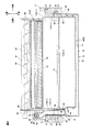
また、プロセスフレーム31は、第2搬送部材の一例としての中継部材41を備えている。
Further, the
中継部材41は、ブラックプロセスカートリッジ9Kの左側に配置されるように、プロセスフレームの31の左側前端部内において、左側の側壁32に支持されている。中継部材41は、連結部42と、搬送管43とを備えている。
The
連結部42は、図2および図3に示すように、左側の側壁32の上側に配置されている。言い換えると、中継部材41は、プロセスフレーム31からベルトユニット21に向かって上側に突出されている。連結部42は、搬送筒44と、オーガスクリュー45と、第1シャッタ部材の一例としての中継部材側シャッタ46とを備えている。
As shown in FIGS. 2 and 3, the connecting
搬送筒44は、前後方向に延び、前後両端が閉鎖された略円筒形状に形成されている。搬送筒44は、第1開口の一例としての中継部材側連通口47と、鍔部48とを有している。
The
中継部材側連通口47は、搬送筒44の後端部の上壁に貫通形成されている。
The relay member side communication port 47 is formed through the upper wall of the rear end portion of the
鍔部48は、搬送筒44の前後方向略中央において、搬送筒44の外周面から径方向外側へ突出し、搬送筒44の周方向に延びる突条として形成されている。
The
オーガスクリュー45は、搬送筒44内において前後方向に沿って設けられている。オーガスクリュー45は、その前端部が搬送筒44の前壁に回転可能に支持され、その後端部が搬送筒44の後壁に回転可能に支持されている。
The
中継部材側シャッタ46は、搬送筒44の後端部に外嵌されている。中継部材側シャッタ46は、前後方向に延びる略円筒形状に形成されている。中継部材側シャッタ46は、搬送筒44の中継部材側連通口47を開放する開位置(図3(b)参照)と、搬送筒44の中継部材側連通口47を閉鎖する閉位置(図6参照)とに、前後方向にスライド可能に設けられている。中継部材側シャッタ46には、ばね収容部49が形成されている。
The relay
ばね収容部49は、中継部材側シャッタ46の前後方向中央において、中継部材側シャッタ46の径方向内側から径方向外側へ拡径されるように形成されている。ばね収容部49内には、搬送筒44の鍔部48が嵌合されている。
The
そして、中継部材側シャッタ46は、鍔部48の後面と、ばね収容部49の後側内周面との間に介在される圧縮ばね50によって、常には、閉位置に配置されるように、後側へ向かって付勢されている。
And the relay
搬送管43は、略円筒形状に形成され、搬送筒44の前端部から前下側へ延び、その前端部において下側へ屈曲して下側へ延びている。なお、搬送管43の上端部は、搬送筒44に連通されている。搬送管43には、供給口40が形成されている。
The
供給口40は、搬送管43の下端部の右壁に貫通形成されている。
(2)廃トナー貯留部
ブラックプロセスカートリッジ9Kは、廃トナー収容部材の一例としての廃トナー貯留部51を備えている。
The
(2) Waste Toner Storage Unit The
廃トナー貯留部51は、上下左右に延びる略ボックス形状に形成されている。廃トナー貯留部51には、回収口52が形成されている。
The waste
回収口52は、廃トナー貯留部51の上端部の左壁に貫通形成されている。
3.ベルトユニットの詳細
(1)ベルトクリーナ
ベルトユニット21は、図1および図3に示すように、ベルトクリーナ61を備えている。
The
3. Details of Belt Unit (1) Belt Cleaner The
ベルトクリーナ61は、ブラックプロセスカートリッジ9Kの後上側において、中間転写ベルト25の上側に配置されている。ベルトクリーナ61は、クリーナフレーム64と、掻き取りブレード65と、掻き取りブラシ66と、オーガスクリュー67とを備えている。
The
クリーナフレーム64は、側面視略矩形のボックス形状に形成されている。クリーナフレーム64には、回収口68が形成されている。また、クリーナフレーム64は、接続部63と受入部62とを備えている。
The
回収口68は、クリーナフレーム64の後端部の下壁に貫通形成されている。
The
接続部63は、クリーナフレーム64の前端部の左壁から左側へ突出し、その左端部が閉鎖された略円筒形状に形成されている。なお、接続部63は、その右端部において、クリーナフレーム64内に連通されている。接続部63には、第2開口の一例としてのベルトクリーナ側連通口71が形成されている。
The connecting
ベルトクリーナ側連通口71は、接続部63の下端部に貫通形成されている。
The belt cleaner
受入部62は、接続部63の下端部に配置され、前後方向に延び、後端部が閉鎖された略円筒形状に形成されている。また、受入部62の前端部は、ベルトクリーナ側連通口71を介して、接続部63内に連通されている。受入部62は、第2シャッタ部材の一例としてのベルトクリーナ側シャッタ70を有している。
The receiving
ベルトクリーナ側シャッタ70は、受入部62内に設けられている。ベルトクリーナ側シャッタ70は、前後方向に延び、前端部が閉鎖された略円筒形状に形成されている。ベルトクリーナ側シャッタ70の前後方向長さは、受入部62の前後方向長さの略半分である。ベルトクリーナ側シャッタ70は、受入部62の後端部内に配置され、ベルトクリーナ側連通口71を開放する開位置(図3(b)参照)と、受入部62の前端部内に配置され、ベルトクリーナ側連通口71を閉鎖する閉位置(図3(a)参照)とに前後方向にスライド可能に設けられている。ベルトクリーナ側シャッタ70は、受入部62の後壁とベルトクリーナ側シャッタ70の前壁との間に介在される圧縮ばね73によって、常には、閉位置に配置されるように、前側へ向かって付勢されている。
The belt
掻き取りブレード65は、図1に示すように、その前端部、すなわち基端部においてクリーナフレーム64の回収口68の前側周縁部に支持されている。掻き取りブレード65は、その後端部、すなわち遊端部において中間転写ベルト25の上側部分の上面に接触されている。掻き取りブレード65は、左右方向に長手の略平板形状に形成されている。
As shown in FIG. 1, the
掻き取りブラシ66は、クリーナフレーム64の後端部内において、回収口68の上側に対向配置されている。掻き取りブラシ66の下端部は、掻き取りブレード65の上面に上側から接触されている。掻き取りブラシ66は、掻き取りブレード65とともにクリーニング部材を構成する。
The scraping
オーガスクリュー67は、クリーナフレーム64の後端部内において、掻き取りブラシ66の前側に配置されている。オーガスクリュー67は、左右方向に延び、その右端部がクリーナフレーム64の右壁に回転可能に支持され、その左端部が接続部63の左壁に回転可能に支持されている。オーガスクリュー67は、接続部63および受入部62とともに第1搬送部材を構成する。また、オーガスクリュー67は、接続部63、受入部62および中継部材41とともに搬送部材を構成する。
(2)ベルトクリーナと中継部材との連結状態
プロセスユニット4が装着位置に配置されているときには、図2および図3(b)に示すように、中間転写ベルト25の左側において、連結部42の後端部がベルトクリーナ61の受入部62内に嵌合されることによって、中継部材41が受入部62に連結されている。すなわち、中継部材41は、プロセスユニット4が装着位置に配置されているときには、ベルトユニット21の左側に隣接配置され、左右方向に投影したときに、ベルトユニット21の投影面内において、ベルトクリーナ61の受入部62に連結されている。
The
(2) Connection state of belt cleaner and relay member When the process unit 4 is disposed at the mounting position, as shown in FIG. 2 and FIG. The
このとき、中継部材側シャッタ46は、その後端部が受入部62の前端部に当接されることにより、圧縮ばね50の付勢力に抗して開位置に配置されている。
At this time, the relay
また、ベルトクリーナ側シャッタ70は、その前端部が搬送筒44の後端部に当接されることにより、圧縮ばね73の付勢力に抗して開位置に配置されている。
Further, the belt cleaner-
そして、ベルトクリーナ側連通口71は、中継部材側連通口47に対向されている。
4.本体ケーシング
本体ケーシング2内には、図2および図6に示すように、ガイド溝81が形成されている。また、本体ケーシング2内には、1対のベルトユニット支持板82と、1対の押圧機構83とが設けられている。
The belt cleaner
4). Main Body Casing As shown in FIGS. 2 and 6, a
ガイド溝81は、ベルトユニット21の下側において、前後方向に延びる略直線形状に形成されている。ガイド溝81は、本体ケーシング2の左右方向側壁の左右方向内面から左右方向外側へ凹む凹溝として形成されている。ガイド溝81内には、プロセスユニット4のガイドころ36およびガイドレール37が嵌合される。
The
1対のベルトユニット支持板82は、本体ケーシング2の上端部において、ベルトユニット21を左右方向外側から挟んで支持するように、左右方向に互いに間隔を隔てて対向配置されている。ベルトユニット支持板82は、前後上下に延びる略平板形状に形成されている。ベルトユニット支持板82は、その上端部において、本体ケーシング2の上壁に固定されている。また、ベルトユニット支持板82の下端部には、複数のドラム位置決め溝84が形成されている。
The pair of belt
複数のドラム位置決め溝84のそれぞれは、複数の感光ドラム11にそれぞれ対応するように、前後方向に互いに間隔を隔てて並列配置されている。ドラム位置決め溝84は、ベルトユニット支持板82の下端縁から上側へ向かって、下側へ開放される側面視略U字形状に切り欠かれている。ドラム位置決め溝84は、感光ドラム11のフランジ部材11Bの上端部を受け入れ可能な溝幅(左右方向長さ)に形成されている。
Each of the plurality of drum positioning grooves 84 is arranged in parallel at intervals in the front-rear direction so as to correspond to each of the plurality of
1対の押圧機構83のそれぞれは、本体ケーシング2の上下方向略中央において、感光ドラム11の突出部11Cの下側に設けられている。押圧機構83は、平行リンク機構であり、固定リンク部材85と、可動リンク部材86と、複数のジョイント部材87とを備えている。
Each of the pair of
固定リンク部材85は、感光ドラム11の突出部11Cの下側に間隔を隔てて設けられている。固定リンク部材85は、本体ケーシング2の左右方向側壁の左右方向内面から左右方向内側へ突出し、前後方向に延びる側面視略直線形状の突条として形成されている。
The fixed
可動リンク部材86は、前後方向に延びる略杆形状に形成されており、固定リンク部材85と平行に設けられている。また、可動リンク部材86は、複数の板ばね部材88を備えている。
The
複数の板ばね部材88は、可動リンク部材86の上面に固定されており、複数の感光ドラム11にそれぞれ対応するように、前後方向に互いに間隔を隔てて並列配置されている。板ばね部材88は、前後方向に延びる金属板からなり、その前後方向両端部が下側へ屈曲されて、上底が下底よりも短い側面視略台形状に形成されている。
The plurality of
複数のジョイント部材87は、前後方向に互いに間隔を隔てて並列配置されている。詳しくは、複数のジョイント部材87は、可動リンク部材86の前後方向両端部と、板ばね部材88の前側近傍とに、1つずつ設けられている。複数のジョイント部材87は、略杆形状に形成されており、その一端部において、可動リンク部材86の下端部に回動可能に連結されており、その他端部において、固定リンク部材85の上端部に回動可能に連結されている。
The plurality of
これにより、押圧機構83は、複数のジョイント部材87が上下方向に起立されて、可動リンク部材86が上側へ進出する押圧位置(図4参照)と、複数のジョイント部材87が前後方向に傾倒されて、可動リンク部材86が下側へ退避される押圧解除位置(図5参照)とに移動可能に設けられている。なお、押圧機構83が押圧解除位置に配置されたときには、可動リンク部材86の前端部は、本体ケーシング2の本体開口部7を介して前側へ突出される。
5.転写残トナーのクリーニング
プリンタ1は、上記した画像形成動作中に、ドラムクリーニングローラ14で感光ドラム11の表面をクリーニングするとともに、ベルトクリーナ61で中間転写ベルト25の表面をクリーニングする。なお、ドラムクリーニングローラ14には、クリーニングバイアスが印加される。
As a result, the
5. Cleaning of Transfer Residual Toner During the image forming operation described above, the
上記した画像形成動作において、感光ドラム11の表面に担持されたトナー像が中間転写ベルト25の下側部分に転写された後には、感光ドラム11の表面に、中間転写ベルト25に転写されなかったトナーが残存する場合がある。なお、以下の説明において、転写されなかったトナーを転写残トナーと記載する。転写残トナーは、残留トナーの一例である。
In the image forming operation described above, after the toner image carried on the surface of the
感光ドラム11の表面に残存する転写残トナーは、感光ドラム11の右側面視時計回り方向への回転に伴って、ドラムクリーニングローラ14の表面に静電気的に保持される。
The transfer residual toner remaining on the surface of the
また、上記した画像形成動作において、中間転写ベルト25の表面に担持されたトナー像が用紙Pに転写された後には、中間転写ベルト25の表面に、転写残トナーが残存する場合がある。
Further, in the image forming operation described above, after the toner image carried on the surface of the
中間転写ベルト25の表面に残存する転写残トナーは、中間転写ベルト25の周回移動に伴って、ベルトクリーナ61の掻き取りブレード65によって中間転写ベルト25の表面から掻き取られる。
The transfer residual toner remaining on the surface of the
掻き取りブレード65によって掻き取られた転写残トナーは、掻き取りブラシ66の回転により、回収口68を介してクリーナフレーム64の前端部内に収容される。
The transfer residual toner scraped off by the
クリーナフレーム64に収容された転写残トナーは、オーガスクリュー67の回転によって左側へ搬送され、接続部63のベルトクリーナ側連通口71、および、中継部材41の中継部材側連通口47を介して中継部材41の連結部42に供給される。
The transfer residual toner accommodated in the
中継部材41の連結部42に供給された転写残トナーは、オーガスクリュー45の回転によって前側へ搬送され、搬送管43へ供給される。
The untransferred toner supplied to the connecting
搬送管43へ供給された転写残トナーは、搬送管43内を下側へ落下し、供給口40および回収口52を介して廃トナー貯留部51内に貯留される。
The untransferred toner supplied to the
また、ドラムクリーニングローラ14の表面に静電気的に保持された転写残トナーは、上記した画像形成動作が実施されていないときに、廃トナー貯留部51に回収される。
Further, the transfer residual toner electrostatically held on the surface of the
詳しくは、ドラムクリーニングローラ14に保持されている転写残トナーは、ドラムクリーニングローラ14に印加されるクリーニングバイアスが制御されることにより、感光ドラム11の周面に吐き出される。
Specifically, the transfer residual toner held on the
感光ドラム11の周面に吐き出された転写残トナーは、感光ドラム11の回転に伴って、中間転写ベルト25に対向される。
The untransferred toner discharged to the peripheral surface of the
すると、感光ドラム11の表面上の転写残トナーは、中間転写ベルト25の表面に転写される。
Then, the transfer residual toner on the surface of the
中間転写ベルト25の表面に転写された転写残トナーは、中間転写ベルト25の周回に伴って、上記したように、ベルトクリーナ61の掻き取りブレード65によって中間転写ベルト25の表面から掻き取られて、クリーナフレーム64内に収容される。
As described above, the transfer residual toner transferred onto the surface of the
その後、クリーナフレーム64に収容された転写残トナーは、オーガスクリュー67の回転によって左側へ搬送され、中継部材41を介して廃トナー貯留部51内に貯留される。
6.プロセスカートリッジの着脱
プロセスカートリッジ9を本体ケーシング2から離脱させるには、まず、フロントカバー8を開放する。
Thereafter, the transfer residual toner accommodated in the
6). Attachment / Removal of Process Cartridge To remove the
すると、図5に示すように、押圧機構83が押圧解除位置に配置されるとともに、複数の感光ドラム11が中間転写ベルト25から下側へ離間されて離間位置に配置される。
Then, as shown in FIG. 5, the
次いで、プロセスカートリッジ9を本体ケーシング2から離脱させるには、プロセスユニット4を前側へ引き出す。
Next, to detach the
すると、中継部材41の連結部42が受入部62から前側へ離間されることにより、中継部材41の受入部62に対する嵌合が解除される。
Then, the
すると、ベルトクリーナ側シャッタ70は、圧縮ばね73の付勢力により閉位置に配置される。また、中継部材側シャッタ46は、圧縮ばね50の付勢力により閉位置に配置される。
Then, the belt
これにより、ベルトクリーナ61から廃トナー貯留部51への転写残トナーの搬送が遮断される。
As a result, the transfer residual toner from the
そして、図6に示すように、プロセスユニット4が引出位置に配置された後、プロセスフレーム31からプロセスカートリッジ9を上側へ離脱させる。
Then, as shown in FIG. 6, after the process unit 4 is arranged at the drawing position, the
これにより、プロセスカートリッジ9の本体ケーシング2からの離脱が完了する。
Thereby, the separation of the
また、プロセスカートリッジ9を本体ケーシング2内に装着するには、上記した離脱作業と逆に、プリンタ1を操作する。
In order to mount the
具体的には、プロセスカートリッジ9を本体ケーシング2内に装着するには、まず、プロセスカートリッジ9をプロセスフレーム31に上側から装着する。
Specifically, to mount the
次いで、プロセスカートリッジ9を本体ケーシング2内に装着するには、プロセスユニット4を後側へ押し込む。
Next, in order to mount the
すると、上記したように、搬送筒44が受入部62内に嵌合されて、ベルトクリーナ側シャッタ70が開位置に配置されるとともに、中継部材側シャッタ46が開位置に配置される。また、ベルトクリーナ側連通口71は、中継部材側連通口47に対向される。
Then, as described above, the
これにより、プロセスユニット4が装着位置に配置される。このとき、プロセスフレーム31は、中間転写ベルト25の下側に間隔を隔てるように複数の感光ドラム11を保持している。
Thereby, the process unit 4 is arranged at the mounting position. At this time, the
次いで、プロセスカートリッジ9を本体ケーシング2内に装着するには、フロントカバー8を閉鎖する。
Next, to mount the
すると、フロントカバー8が、押圧機構83の可動リンク部材86の前端部に前側から当接され、フロントカバー8の閉鎖に伴って、可動リンク部材86がフロントカバー8によって後側へ押圧される。
Then, the
そして、図4に示すように、フロントカバー8が完全に閉鎖されると、押圧機構83が押圧位置に配置されるとともに、複数の感光ドラム11が上側へ移動されて、中間転写ベルト25に下側から接触される接触位置に配置される。このとき、感光ドラム11は、そのフランジ部材11Bの上端部がベルトユニット支持板82のドラム位置決め溝84内に嵌合されることにより、ベルトユニット21に対して位置決めされる。
Then, as shown in FIG. 4, when the
これにより、プロセスカートリッジ9の本体ケーシング2内への装着が完了する。
7.作用効果
(1)このプリンタ1によれば、図4および図5に示すように、複数の感光ドラム11は、プロセスフレーム31が装着位置に配置されている状態で、中間転写ベルト25に接触される接触位置(図4参照)と、中間転写ベルト25から離間される離間位置(図5参照)とに移動可能である。
Thereby, the mounting of the
7). Operation and Effect (1) According to the
これにより、プロセスフレーム31を装着位置に配置した後に、複数の感光ドラム11を中間転写ベルト25に接触させることができる。
As a result, the plurality of
そのため、プロセスフレーム31の移動とは別の動作で、複数の感光ドラム11を中間転写ベルト25に対して位置決めすることができる。
Therefore, the plurality of
その結果、複数の感光ドラム11をベルトユニット21に対して容易に位置決めすることができる。
(2)また、このプリンタ1によれば、図4および図5に示すように、複数の感光ドラム11は、上下方向に移動可能である。
As a result, the plurality of
(2) Also, according to the
そのため、ベルトユニット21に対して複数の感光ドラム11が上下方向に接離可能であり、プロセスフレーム31が前後方向に移動可能である場合であっても、複数の感光ドラム11をベルトユニット21に対して容易に位置決めすることができる。
(3)また、このプリンタ1によれば、図4および図5に示すように、プロセスフレーム31を装着位置から引出位置へ移動させる動作を利用して、中継部材41をベルトクリーナ61の受入部62から分離し、ベルトクリーナ61から廃トナー貯留部51への転写残トナーの搬送を遮断することができる。
(4)また、このプリンタ1によれば、図2に示すように、中継部材41の接続部63は、プロセスフレーム31が装着位置に配置されている状態で、ベルトユニット21の左側に隣接配置されている。
Therefore, even if the plurality of
(3) Also, according to the
(4) Also, according to this
そのため、ベルトユニット21の左側の空間を利用して、効率よく中継部材41を配置することができる。
(5)また、このプリンタ1によれば、図2に示すように、中継部材41は、プロセスフレーム31が装着位置に配置されている状態で、プロセスフレーム31から上側に突出されている。
Therefore, the
(5) Also, according to the
そのため、ベルトユニット21の受入部62を下側へ突出させる必要がなく、プロセスフレーム31を移動させるときに受入部62がプロセスフレーム31に干渉することを防止できる。
(6)また、このプリンタ1によれば、図3(b)に示すように、中継部材41は、プロセスフレーム31が装着位置に配置されている状態で、左右方向に投影したときに、ベルトユニット21の投影面内において、ベルトクリーナ61の受入部62に連結されていてもよい。
Therefore, it is not necessary to project the receiving
(6) Further, according to the
そのため、ベルトユニット21の左側の空間を利用して、中継部材41と、ベルトクリーナ61の受入部62とを連結することができる。
(7)また、このプリンタ1によれば、図2に示すように、掻き取りブレード65および掻き取りブラシ66によってクリーニングされた転写残トナーを、オーガスクリュー67によって左側へ集めて、効率よく回収することができる。
(8)また、このプリンタ1によれば、図3(b)および図5に示すように、プロセスフレーム31を引出位置に配置したときに、ベルトクリーナ側連通口71をベルトクリーナ側シャッタ70で閉鎖するとともに、中継部材側連通口47を中継部材側シャッタ46で閉鎖することができる。
Therefore, the
(7) Further, according to the
(8) Also, according to this
そのため、プロセスフレーム31を引出位置に配置したときに、ベルトクリーナ61から廃トナー貯留部51への転写残トナーの搬送を確実に遮断することができ、また、ベルトクリーナ側連通口71や中継部材側連通口47からの転写残トナーの漏れを確実に防止することができる。
(9)また、このプリンタ1によれば、図5に示すように、プロセスフレーム31が装着位置に配置され、フロントカバー8が開位置に配置されているときには、プロセスフレーム31は、複数の感光ドラム11の上側への移動を許容するように、中間転写ベルト25の下側に間隔を隔てるように複数の感光ドラム11を保持している。
For this reason, when the
(9) Also, according to this
そのため、プロセスフレーム31が装着位置に配置されているときに、確実に、複数の感光ドラム11を移動させることができる。
Therefore, the plurality of
1 プリンタ
2 本体ケーシング
11 感光ドラム
21 ベルトユニット
25 中間転写ベルト
31 プロセスフレーム
41 中継部材
46 中継部材側シャッタ
47 中継部材側連通口
51 廃トナー貯留部
62 受入部
63 接続部
65 掻き取りブレード
66 掻き取りブラシ
67 オーガスクリュー
70 ベルトクリーナ側シャッタ
71 ベルトクリーナ側連通口
DESCRIPTION OF
Claims (8)
感光体を有する複数のプロセスカートリッジと、
前記複数のプロセスカートリッジを支持するように構成され、前記装置本体内に配置される内側位置と、前記装置本体外に配置される外側位置との間を移動するように構成される移動部材と、
ベルトと、前記ベルトに残留した残留トナーをクリーニングするように構成されるクリーニング部材と、を有するベルトユニットと、
前記移動部材に支持され、前記クリーニング部材によってクリーニングされた残留トナーを収容するように構成される廃トナー収容部材と、
前記クリーニング部材によってクリーニングされた残留トナーを前記廃トナー収容部材に搬送するように構成される搬送部材と
を備え、
前記移動部材は、前記内側位置から前記外側位置へ、第1方向に移動するように構成され、
前記複数の感光体は、前記移動部材が前記複数のプロセスカートリッジを支持した状態で、前記移動部材が前記内側位置に配置されているときに、前記ベルトに接触される接触位置と、前記ベルトから離間される離間位置とに移動するように構成され、かつ、前記接触位置から前記離間位置へ、前記第1方向と交差する第2方向に移動するように構成され、
前記搬送部材は、第1搬送部材と、前記第1搬送部材に対して分離可能に連結されるように構成される第2搬送部材と、を有し、
前記ベルトユニットは、前記第1搬送部材を有し、
前記移動部材は、前記第2搬送部材を有することを特徴とする、画像形成装置。 The device body;
A plurality of process cartridges having photoreceptors;
A moving member configured to support the plurality of process cartridges and configured to move between an inner position disposed in the apparatus main body and an outer position disposed outside the apparatus main body;
A belt unit having a belt and a cleaning member configured to clean residual toner remaining on the belt;
A waste toner storage member supported by the moving member and configured to store residual toner cleaned by the cleaning member;
A transport member configured to transport residual toner cleaned by the cleaning member to the waste toner storage member;
The moving member is configured to move in a first direction from the inner position to the outer position;
The plurality of photoconductors are in contact with the belt when the moving member is disposed at the inner position in a state where the moving member supports the plurality of process cartridges, and from the belt Configured to move to a spaced position that is spaced apart, and configured to move from the contact position to the spaced position in a second direction that intersects the first direction;
The transport member includes a first transport member and a second transport member configured to be separably connected to the first transport member;
The belt unit has the first conveying member,
The image forming apparatus , wherein the moving member includes the second conveying member .
前記第2搬送部材は、前記移動部材が前記内側位置に配置された状態で前記第1開口に対向される第2開口と、前記移動部材が前記内側位置に配置された状態で前記第2開口を開放し、前記移動部材が前記外側位置に配置された状態で前記第2開口を閉鎖するように構成される第2シャッタ部材とを有し、
前記第1シャッタ部材は、前記第1方向に沿って移動することにより、前記第1開口を開放または閉鎖し、
前記第2シャッタ部材は、前記第1方向に沿って移動することにより、前記第2開口を開放または閉鎖することを特徴とする、請求項1ないし5のいずれか一項に記載の画像形成装置。 The first conveying member opens the first opening in a state where the first opening and the moving member are disposed at the inner position, and the first opening in a state where the moving member is disposed at the outer position. A first shutter member configured to close
The second transport member includes a second opening facing the first opening in a state where the moving member is disposed at the inner position, and the second opening in a state where the moving member is disposed at the inner position. And a second shutter member configured to close the second opening in a state where the moving member is disposed at the outer position,
The first shutter member opens or closes the first opening by moving along the first direction,
Said second shutter member, said by moving along a first direction, said second opening, characterized in that opening or closing, images according to any one of claims 1 stomach Shi 5 Forming equipment.
感光体を有する複数のプロセスカートリッジと、
前記複数のプロセスカートリッジを支持するように構成され、前記装置本体内に配置される内側位置と、前記装置本体外に配置される外側位置との間を移動するように構成される移動部材と、
ベルトと、前記ベルトに残留した残留トナーをクリーニングするように構成されるクリーニング部材と、を有するベルトユニットと、
前記移動部材に支持され、前記クリーニング部材によってクリーニングされた残留トナーを収容するように構成される廃トナー収容部材と、
前記クリーニング部材によってクリーニングされた残留トナーを前記廃トナー収容部材に搬送するように構成される搬送部材と
を備え、
前記複数の感光体は、前記移動部材が前記複数のプロセスカートリッジを支持した状態で、前記移動部材が前記内側位置に配置されているときに、前記ベルトに接触される接触位置と、前記ベルトから離間される離間位置とに移動するように構成され、
前記搬送部材は、第1搬送部材と、前記第1搬送部材に対して分離可能に連結されるように構成される第2搬送部材と、を有し、
前記ベルトユニットは、前記第1搬送部材を有し、
前記移動部材は、前記第2搬送部材を有することを特徴とする、画像形成装置。 The device body;
A plurality of process cartridges having photoreceptors;
A moving member configured to support the plurality of process cartridges and configured to move between an inner position disposed in the apparatus main body and an outer position disposed outside the apparatus main body;
A belt unit having a belt and a cleaning member configured to clean residual toner remaining on the belt;
A waste toner storage member supported by the moving member and configured to store residual toner cleaned by the cleaning member;
A conveying member configured to convey residual toner cleaned by the cleaning member to the waste toner containing member;
With
The plurality of photoconductors are in contact with the belt when the moving member is disposed at the inner position in a state where the moving member supports the plurality of process cartridges, and from the belt Configured to move to a spaced apart position,
The transport member includes a first transport member and a second transport member configured to be separably connected to the first transport member;
The belt unit has the first conveying member,
The moving member is characterized by having the second conveying member, images forming device.
Priority Applications (1)
| Application Number | Priority Date | Filing Date | Title |
|---|---|---|---|
| JP2013117475A JP6186899B2 (en) | 2012-10-31 | 2013-06-04 | Image forming apparatus |
Applications Claiming Priority (3)
| Application Number | Priority Date | Filing Date | Title |
|---|---|---|---|
| JP2012241110 | 2012-10-31 | ||
| JP2012241110 | 2012-10-31 | ||
| JP2013117475A JP6186899B2 (en) | 2012-10-31 | 2013-06-04 | Image forming apparatus |
Publications (2)
| Publication Number | Publication Date |
|---|---|
| JP2014112187A JP2014112187A (en) | 2014-06-19 |
| JP6186899B2 true JP6186899B2 (en) | 2017-08-30 |
Family
ID=51169352
Family Applications (1)
| Application Number | Title | Priority Date | Filing Date |
|---|---|---|---|
| JP2013117475A Active JP6186899B2 (en) | 2012-10-31 | 2013-06-04 | Image forming apparatus |
Country Status (1)
| Country | Link |
|---|---|
| JP (1) | JP6186899B2 (en) |
Families Citing this family (2)
| Publication number | Priority date | Publication date | Assignee | Title |
|---|---|---|---|---|
| JP6390457B2 (en) * | 2015-02-06 | 2018-09-19 | ブラザー工業株式会社 | Image forming apparatus |
| JP6743457B2 (en) * | 2016-03-31 | 2020-08-19 | ブラザー工業株式会社 | Process cartridge |
Family Cites Families (8)
| Publication number | Priority date | Publication date | Assignee | Title |
|---|---|---|---|---|
| JP2007218936A (en) * | 2006-02-14 | 2007-08-30 | Konica Minolta Business Technologies Inc | Process cartridge and image forming apparatus |
| JP4280772B2 (en) * | 2006-12-28 | 2009-06-17 | キヤノン株式会社 | Process cartridge and electrophotographic image forming apparatus |
| JP2009048112A (en) * | 2007-08-22 | 2009-03-05 | Konica Minolta Business Technologies Inc | Method for controlling conveyance of waste toner for image forming apparatus and image forming apparatus |
| JP4591516B2 (en) * | 2008-01-29 | 2010-12-01 | ブラザー工業株式会社 | Image forming apparatus |
| JP5125801B2 (en) * | 2008-06-24 | 2013-01-23 | 富士ゼロックス株式会社 | Image forming apparatus |
| JP5471838B2 (en) * | 2010-05-27 | 2014-04-16 | ブラザー工業株式会社 | Image forming apparatus |
| JP5750923B2 (en) * | 2011-02-10 | 2015-07-22 | ブラザー工業株式会社 | Image forming apparatus |
| JP5240307B2 (en) * | 2011-02-21 | 2013-07-17 | ブラザー工業株式会社 | Image forming apparatus |
-
2013
- 2013-06-04 JP JP2013117475A patent/JP6186899B2/en active Active
Also Published As
| Publication number | Publication date |
|---|---|
| JP2014112187A (en) | 2014-06-19 |
Similar Documents
| Publication | Publication Date | Title |
|---|---|---|
| US12013658B2 (en) | Image forming apparatus having cartridge and waste developer accommodating portion | |
| US8768208B2 (en) | Image forming apparatus with cartridge supporting member and preventing members for ensuring mounting of cartridges in associated mounting portions | |
| JP6111835B2 (en) | Image forming apparatus | |
| US20120288303A1 (en) | Electrophotographic image forming apparatus | |
| JP6311518B2 (en) | Image forming apparatus | |
| US8934809B2 (en) | Image forming device capable of reliably collecting matter deposited on endless belt in storage member and facilitating maintenance of storage member | |
| US9134686B2 (en) | Image forming apparatus provided with movable conveying unit | |
| JP5942683B2 (en) | Image forming apparatus | |
| JP6142680B2 (en) | Image forming apparatus | |
| JP6186899B2 (en) | Image forming apparatus | |
| JP5350194B2 (en) | Electrophotographic image forming apparatus | |
| JP6365378B2 (en) | Image forming apparatus | |
| JP6687896B2 (en) | Powder container and image forming apparatus | |
| JP6015437B2 (en) | Image forming apparatus and image forming structure | |
| JP6428445B2 (en) | Image forming apparatus | |
| JP5891994B2 (en) | Image forming apparatus |
Legal Events
| Date | Code | Title | Description |
|---|---|---|---|
| A621 | Written request for application examination |
Free format text: JAPANESE INTERMEDIATE CODE: A621 Effective date: 20160527 |
|
| A131 | Notification of reasons for refusal |
Free format text: JAPANESE INTERMEDIATE CODE: A131 Effective date: 20170314 |
|
| A977 | Report on retrieval |
Free format text: JAPANESE INTERMEDIATE CODE: A971007 Effective date: 20170315 |
|
| A521 | Written amendment |
Free format text: JAPANESE INTERMEDIATE CODE: A523 Effective date: 20170420 |
|
| TRDD | Decision of grant or rejection written | ||
| A01 | Written decision to grant a patent or to grant a registration (utility model) |
Free format text: JAPANESE INTERMEDIATE CODE: A01 Effective date: 20170704 |
|
| A61 | First payment of annual fees (during grant procedure) |
Free format text: JAPANESE INTERMEDIATE CODE: A61 Effective date: 20170717 |
|
| R150 | Certificate of patent or registration of utility model |
Ref document number: 6186899 Country of ref document: JP Free format text: JAPANESE INTERMEDIATE CODE: R150 |