JP6186614B2 - Fitting tool and bag with fitting tool - Google Patents
Fitting tool and bag with fitting tool Download PDFInfo
- Publication number
- JP6186614B2 JP6186614B2 JP2013036000A JP2013036000A JP6186614B2 JP 6186614 B2 JP6186614 B2 JP 6186614B2 JP 2013036000 A JP2013036000 A JP 2013036000A JP 2013036000 A JP2013036000 A JP 2013036000A JP 6186614 B2 JP6186614 B2 JP 6186614B2
- Authority
- JP
- Japan
- Prior art keywords
- fitting
- base material
- slit
- bag body
- bag
- Prior art date
- Legal status (The legal status is an assumption and is not a legal conclusion. Google has not performed a legal analysis and makes no representation as to the accuracy of the status listed.)
- Active
Links
Images


Description
本発明は、嵌合具及び嵌合具付き袋体に関する。 The present invention relates to a fitting tool and a bag body with a fitting tool.
食品、薬品、雑貨等を収容する袋体としては、内容物を収容する袋本体と、該袋本体の開口部近傍の内面に、該開口部を開閉自在に封じるように取り付けられた嵌合具と、を具備する嵌合具付き袋体が広く用いられている。
嵌合具としては、例えば、帯状の基材及び該基材の長手方向に沿って設けられた雄型嵌合部とを有する第1の嵌合部材と、帯状の基材及び該基材の長手方向に沿って設けられた雌型嵌合部とを有する第2の嵌合部材と、を有する嵌合具が挙げられる(例えば、特許文献1)。該嵌合具においては、雄型嵌合部と雌型嵌合部とが着脱自在に嵌合できるようになっている。袋本体の開口部近傍において向かい合う一方の内面に第1の嵌合部材の基材を取り付け、他方の内面に第2の嵌合部材の基材を取り付けて、雄型嵌合部と雌型嵌合部とを着脱させることで、袋本体の開口部の開閉が繰り返し行える。
As a bag body for storing food, medicine, miscellaneous goods, etc., a bag main body for storing contents, and a fitting tool attached to an inner surface in the vicinity of the opening of the bag main body so as to be able to open and close the opening. And the bag body with a fitting tool which comprises these is widely used.
As a fitting tool, for example, a first fitting member having a belt-like base material and a male fitting portion provided along the longitudinal direction of the base material, a belt-like base material, and the base material There is a fitting tool having a second fitting member having a female fitting portion provided along the longitudinal direction (for example, Patent Document 1). In the fitting tool, the male fitting portion and the female fitting portion can be detachably fitted. A base material of the first fitting member is attached to one inner surface facing in the vicinity of the opening of the bag body, and a base material of the second fitting member is attached to the other inner surface. By opening and closing the joint, the opening and closing of the opening of the bag body can be repeated.
このような嵌合具付き袋体においては、嵌合具によって開口部を開封する作業が難しいことがある。具体的には、嵌合具によって開口部を開封する際には、袋本体における第1の嵌合部材が取り付けられた側の開口端と、第2の嵌合部材が取り付けられた側の開口端とをそれぞれ把持し、それら各々の開口端を離間させるように引っ張ることで、雄型嵌合部を雌型嵌合部から脱離させて開封する。しかし、嵌合具の雄型嵌合部と雌型嵌合部とを嵌合して開口部を閉じている状態では、袋本体の対向する開口端同士が密着した状態となりやすく、それぞれの開口端を把持することが難しい。そのため、袋体の開封に時間がかかることがある。 In such a bag with a fitting tool, it may be difficult to open the opening with the fitting tool. Specifically, when opening the opening with the fitting tool, the opening end of the bag body on the side where the first fitting member is attached and the opening on the side where the second fitting member is attached. The male fitting part is detached from the female fitting part and opened by gripping the ends and pulling the respective opening ends so as to be separated from each other. However, in a state where the male fitting portion and the female fitting portion of the fitting tool are fitted and the opening portion is closed, the opposed opening ends of the bag body are likely to be in close contact with each other. It is difficult to grip the edge. Therefore, it may take time to open the bag.
本発明は、嵌合具によって閉じた袋本体の開口部を容易に開封できる嵌合具、及び該嵌合具を具備する嵌合具付き袋体を提供する。 The present invention provides a fitting that can easily open the opening of the bag body closed by the fitting, and a bag with a fitting that includes the fitting.
本発明の嵌合具は、一対の帯状の第1の嵌合部材及び第2の嵌合部材を有し、前記第1の嵌合部材が、帯状の第1の基材と、前記第1の基材に長手方向に沿って設けられた第1の嵌合部と、を有し、第1のスリット部及び第2のスリット部のいずれか一方又は両方が形成され、前記第1のスリット部は、前記第1の基材における前記第1の嵌合部と第1の側縁との間に前記第1の基材の長手方向に沿うように直線状に形成され、前記第1のスリット部の幅は0.1〜20.0mmであり、前記第1のスリット部の前記第1の嵌合部側の縁と、前記第1の嵌合部の中心軸との距離が0.5〜40.0mmであり、前記第2のスリット部は、前記第2の基材における前記第2の嵌合部と第1の側縁との間に前記第2の基材の長手方向に沿うように直線状に形成され、前記第2のスリット部の幅は0.1〜20.0mmであり、前記第2のスリット部の前記第2の嵌合部側の縁と、前記第2の嵌合部の中心軸との距離が0.5〜40.0mmである。 The fitting tool of the present invention has a pair of band-shaped first fitting members and a second fitting member, and the first fitting member includes a band-shaped first base material and the first fitting member. And a first fitting portion provided along the longitudinal direction of the base material , wherein one or both of the first slit portion and the second slit portion are formed, and the first slit The portion is formed linearly between the first fitting portion and the first side edge of the first base so as to be along the longitudinal direction of the first base, and the first base The width of the slit portion is 0.1 to 20.0 mm, and the distance between the edge on the first fitting portion side of the first slit portion and the central axis of the first fitting portion is 0.00. a 5~40.0Mm, the second slit portion, in the longitudinal direction of the second base member between said second fitting portion and the first side edge of said second substrate Along Is formed in a linear shape, the width of the second slit portion are 0.1~20.0Mm, and said second fitting portion side edge of the second slit portion, said second fitting The distance from the central axis of the part is 0.5 to 40.0 mm .
本発明の嵌合具においては、前記第1のスリット部と第2のスリット部の両方が形成されていることが好ましい。 In fitting tool of the present invention, it is preferable that both of the first slit portion and the second slit portions are formed.
本発明の嵌合具付き袋体は、内容物を収容する袋本体と、前記袋本体の内面に取り付けられた本発明の嵌合具と、を具備し、前記嵌合具が、前記第1の基材の第1の側縁と前記第2の基材の第1の側縁が前記袋本体に形成される開口部側になるように取り付けられている。 The bag body with a fitting tool of the present invention comprises a bag main body for storing contents, and the fitting tool of the present invention attached to the inner surface of the bag main body, wherein the fitting tool is the first fitting. The first side edge of the base material and the first side edge of the second base material are attached so as to be on the opening side formed in the bag body.
本発明の嵌合具を用いれば、嵌合具によって閉じた袋本体の開口部を容易に開封できる。
本発明の嵌合具付き袋体は、嵌合具によって閉じた袋本体の開口部を容易に開封できる。
If the fitting tool of this invention is used, the opening part of the bag main body closed with the fitting tool can be opened easily.
The bag body with a fitting tool of the present invention can easily open the opening of the bag body closed by the fitting tool.
<嵌合具>
以下、本発明の嵌合具の一例を示して詳細に説明する。
嵌合具10は、図1及び図2に示すように、一対の帯状の第1の嵌合部材12と第2の嵌合部材14とを有する。
第1の嵌合部材12は、帯状の第1の基材16と、第1の基材16の対向面16aに長手方向に沿って設けられた突条の第1の嵌合部18とを有する。第2の嵌合部材14は、帯状の第2の基材20と、第2の基材20の対向面20aに長手方向に沿って設けられ、第1の嵌合部18と着脱自在に嵌合する第2の嵌合部22とを有する。
嵌合具10は、袋本体に取り付けられる際、第1の基材16の第1の側縁16b及び第2の基材20の第1の側縁20bが袋本体の開口部側、第1の基材16の第2の側縁16c及び第2の基材20の第2の側縁20cが袋本体の底側となるように取り付けられる。
<Fitting tool>
Hereinafter, an example of the fitting tool of the present invention will be shown and described in detail.
As shown in FIGS. 1 and 2, the
The
When the
第1の基材16としては、特に限定されず、公知の嵌合具の基材に使用されるものが使用でき、積層フィルムからなる基材が好ましい。積層フィルムからなる第1の基材16としては、例えば、対向面16a側から、耐熱層とヒートシール層が積層されたフィルムが挙げられる。また、第1の基材16は、耐熱層とヒートシール層の間にバリア層を有していてもよい。
耐熱層の材質としては、二軸延伸ナイロン、二軸延伸ポリプロピレン等が挙げられる。
ヒートシール層の材質としては、直鎖状低密度ポリエチレン、無延伸ポリプロピレン、エチレン−酢酸ビニル共重合体、アイオノマー等が挙げられる。
バリア層の材質としては、ポリビニルアルコール等が挙げられる。
It does not specifically limit as the
Examples of the material for the heat-resistant layer include biaxially stretched nylon and biaxially stretched polypropylene.
Examples of the material for the heat seal layer include linear low density polyethylene, unstretched polypropylene, ethylene-vinyl acetate copolymer, and ionomer.
Examples of the material for the barrier layer include polyvinyl alcohol.
第1の基材16は、1種の樹脂からなっていてもよく、2種以上の樹脂を含む樹脂組成物からなっていてもよい。また、第1の基材16には、必要に応じて安定剤、酸化防止剤、滑剤、帯電防止剤、着色剤等の公知の添加剤が添加されていてもよい。
また、第1の基材16は、積層フィルムからなる基材には限定されず、単層フィルムからなる基材であってもよい。
第2の基材20としては、第1の基材16と同じ基材が挙げられ、好ましい態様も同じである。
The
Moreover, the
As the
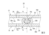
第1の嵌合部18は、第1の基材16の対向面16aに、第1の基材16の長手方向に沿って設けられている。第1の嵌合部18は、図2及び図3に示すように、第1の基材16の対向面16aから立ち上がる幹部18aと、幹部18aの先端部に設けられ、幹部18aよりも大きい断面略半円形状の頭部18bを有する雄型嵌合部である。
第2の嵌合部22は、第2の基材20の対向面20aに、第2の基材20の長手方向に沿って設けられている。第2の基材20は、図2及び図3に示すように、第2の基材20の対向面20aから断面円弧状に立ち上がる第1のアーム部22aと第2のアーム部22bからなり、第1のアーム部22aと第2のアーム部22bによって凹部22cが形成されている雌型嵌合部である。
第1の嵌合部18と第2の嵌合部22は、第1の嵌合部18の頭部18bを第2の嵌合部22の凹部22cに嵌め込むことで、着脱自在に嵌合できるようになっている。
The
The
The
第1の嵌合部18及び第2の嵌合部22の断面形状は、第1の嵌合部18と第2の嵌合部22を互いに着脱することで、袋本体の開口部の開閉が繰り返し行えるものであればよく、公知の断面形状を採用できる。
第1の嵌合部18及び第2の嵌合部22の材質としては、第1の基材16及び第1の嵌合部18と同じ材質が使用できる。
The cross-sectional shapes of the
As the material of the
図1〜3に示すように、第1の基材16には、第1の嵌合部18と第1の側縁16bの間に、第1の基材16の長手方向に沿って直線状の第1のスリット部24が形成されている。第1のスリット部24が形成されていることで、第1の基材16が第1のスリット部24の部分で折れ曲がりやすくなる。そのため、第1の嵌合部18と第2の嵌合部22とを嵌合した状態でも、第1の基材16における第1のスリット部24よりも第1の側縁16b側が開きやすい。これにより、第1の基材16の第1の側縁16bが袋本体の開口部側となるように嵌合具10を取り付けた袋体では、第1の嵌合部18と第2の嵌合部22を嵌合して開口部を閉じた状態でも、第1の嵌合部材12が取り付けられた側の袋本体の開口端が第1の基材16と共に曲がって開きやすく、該開口端を把持して開封することが容易になる。
As shown in FIGS. 1 to 3, the
第1のスリット部24は、第1の基材16の長手方向に連続的に形成されていてもよく、断続的に破線状に形成されていてもよい。この例では、第1のスリット部24は、第1の基材16の長手方向に沿って断続的に破線状に形成されている。
第1の嵌合部18と第2の嵌合部22とを嵌合した状態で第1の基材16における第1のスリット部24よりも第1の側縁16b側がより開きやすくなる点から、第1のスリット部24は、第1の基材16における長手方向の全長にわたって形成されていることが好ましい。
The 1st slit
From the point that the
第1のスリット部24と第1の嵌合部18との距離d1(図3)は、0.5〜40.0mmが好ましく、1.0〜20.0mmがより好ましい。前記距離d1が大きいほど、第1のスリット部24を形成することが容易になる。前記距離d1が小さいほど、袋本体における第1の嵌合部材12を取り付けた側の開口端がより大きく開きやすくなり、開封作業がより容易になる。
なお、第1のスリット部24と第1の嵌合部18との距離d1とは、第1のスリット部24における第1の嵌合部18側の縁と、第1の嵌合部18の中心軸Lとの距離を意味する。
The distance d 1 (FIG. 3) between the
Note that the distance d 1 between the
第1のスリット部24の幅d2(図3)は、0.1〜20.0mmが好ましく、0.5〜10.0mmがより好ましい。第1のスリット部24の幅d2が下限値以上であれば、袋本体における第1の嵌合部材12を取り付けた側の開口端がより開きやすくなり、開封作業がより容易になる。第1のスリット部24の幅d2が上限値以下であれば、第1の嵌合部材12の取り扱い性がより良好になり、嵌合具10を袋本体に取り付けることが容易になる。
The width d 2 (FIG. 3) of the
第2の基材20には、第2の嵌合部22と第1の側縁20bの間に、第2の基材20の長手方向に沿って直線状の第2のスリット部26が形成されている。第2のスリット部26が形成されていることで、第2の基材20が第2のスリット部26の部分で折れ曲がりやすくなる。そのため、第1の嵌合部18と第2の嵌合部22とを嵌合した状態でも、第2の基材20における第2のスリット部26よりも第1の側縁20b側が開きやすい。これにより、第2の基材20の第1の側縁20bが袋本体の開口部側となるように嵌合具10を取り付けた袋体では、第1の嵌合部18と第2の嵌合部22を嵌合して開口部を閉じた状態でも、第2の嵌合部材14が取り付けられた側の袋本体の開口端が第2の基材20と共に曲がって開きやすく、該開口端を把持して開封することが容易になる。
In the
第2のスリット部26は、第2の基材20の長手方向に連続的に形成されていてもよく、断続的に破線状に形成されていてもよい。この例では、第2のスリット部26は、第2の基材20の長手方向に沿って断続的に破線状に形成されている。
第1の嵌合部18と第2の嵌合部22とを嵌合した状態で第2の基材20における第2のスリット部26よりも第1の側縁20b側がより開きやすくなる点から、第2のスリット部26は、第2の基材20における長手方向の全長にわたって形成されていることが好ましい。
The
From the point that the
第2のスリット部26と第2の嵌合部22との距離d3(図3)は、0.5〜40.0mmが好ましく、1.0〜20.0mmがより好ましい。前記距離d3が大きいほど、第2のスリット部26を形成することが容易になる。前記距離d3が小さいほど、袋本体における第2の嵌合部材14を取り付けた側の開口端がより大きく開きやすくなり、開封作業がより容易になる。
なお、第2のスリット部26と第2の嵌合部22との距離d3とは、第2のスリット部26における第2の嵌合部22側の縁と、第2の嵌合部22の中心軸Lとの距離を意味する。
The distance d 3 (FIG. 3) between the
The distance d 3 between the
第2のスリット部26の幅d4(図3)は、0.1〜20.0mmが好ましく、0.5〜10.0mmがより好ましい。第2のスリット部26の幅d4が下限値以上であれば、袋本体における第2の嵌合部材14を取り付けた側の開口端がより開きやすくなり、開封作業がより容易になる。第2のスリット部26の幅d4が上限値以下であれば、第2の嵌合部材14の取り扱い性がより良好になり、嵌合具10を袋本体に取り付けることが容易になる。
The width d 4 (FIG. 3) of the
第1の基材16における第1のスリット部24の幅方向の位置と、第2の基材20における第2のスリット部26の幅方向の位置は、同じであってもよく、異なっていてもよい。開封作業がより容易になる点では、第1の基材16における第1のスリット部24の幅方向の位置と、第2の基材20における第2のスリット部26の幅方向の位置は同じであることが好ましい。
The position in the width direction of the
(製造方法)
嵌合具10の製造方法としては、特に限定されず、例えば、押出成形によって基材と嵌合部を有する帯状の嵌合部材を形成した後に、レーザー、刃物等を用いてスリット部を形成する方法等が挙げられる。
(Production method)
The manufacturing method of the fitting 10 is not particularly limited. For example, after forming a band-like fitting member having a base material and a fitting portion by extrusion molding, a slit portion is formed using a laser, a cutter, or the like. Methods and the like.
(作用効果)
以上説明した嵌合具10にあっては、第1の基材16における第1の嵌合部18と第1の側縁16bとの間に第1のスリット部24が形成され、第2の基材20における第2の嵌合部22と第1の側縁20bとの間に第2のスリット部26が形成されていることで、第1の嵌合部18と第2の嵌合部22を嵌合していても第1の基材16の第1の側縁16b側と第2の基材20の第1の側縁20b側が折れ曲がって開きやすい。そのため、嵌合具10を取り付けた袋本体の開口部を開封する際、袋本体の開口端が第1の基材16及び第2の基材20と共に折れ曲がって開きやすく、それら開口端を把持して開封することが容易である。
(Function and effect)
In the
なお、本発明の嵌合具は、前記した嵌合具10には限定されない。
例えば、第1の基材又は第2の基材のいずれかのみにスリット部が形成された嵌合具であってもよい。該嵌合具においても、スリット部が形成された基材を有する嵌合部材が取り付けられた側の袋本体の開口端が開きやすくなるため、開封作業が容易になる。本発明の嵌合具としては、嵌合具で閉じた袋本体の開口部の開封作業がより容易になる点から、嵌合具10のように、第1の基材と第2の基材の両方にスリット部が形成された嵌合具が好ましい。
The fitting tool of the present invention is not limited to the
For example, the fitting tool in which the slit portion is formed only in either the first base material or the second base material may be used. Also in the fitting tool, the opening end of the bag body on the side to which the fitting member having the base material on which the slit portion is formed is easily opened, so that the opening operation is facilitated. As the fitting tool of the present invention, the first base material and the second base material, like the
また、第1の嵌合部と第2の嵌合部をそれぞれ複数の雄型嵌合部からなる嵌合部とし、各々の雄型嵌合部の頭部を対向する2つの雄型嵌合部の間にそれぞれ挿入するように互いに嵌め込むことで、袋本体の開口部を開閉する嵌合具としてもよい。また、第1の嵌合部と第2の嵌合部をそれぞれ1つ以上の雌型嵌合部とし、それら雌型嵌合部同士を互いに嵌め込むことで、袋本体の開口部を開閉する嵌合具としてもよい。 Further, the first fitting portion and the second fitting portion are each a fitting portion composed of a plurality of male fitting portions, and two male fittings facing the heads of the respective male fitting portions. It is good also as a fitting tool which opens and closes the opening part of a bag main body by mutually fitting so that it may each insert between parts. Further, each of the first fitting portion and the second fitting portion is one or more female fitting portions, and the opening portions of the bag body are opened and closed by fitting the female fitting portions to each other. It is good also as a fitting tool.
<嵌合具付き袋体>
以下、本発明の嵌合具付き袋体の一例として、前述した嵌合具10を備えた嵌合具付き袋体1(以下、「袋体1」という。)について説明する。
本実施形態の袋体1は、図4に示すように、内容物を収容する密封された状態の袋本体30と、袋本体30内の上部の内面に、横方向に沿って取り付けられた嵌合具10とを具備している。
<Bag with fittings>
Hereinafter, as an example of a bag body with a fitting tool of the present invention, a bag body with a fitting tool 1 (hereinafter referred to as “
As shown in FIG. 4, the
袋本体30は、第1のフィルム材32と第2のフィルム材34が重ね合わされ、それらの周縁部36が全てヒートシールされることで形成されており、密封された状態になっている。また、袋本体30における嵌合具10よりも上部側には、横方向に沿って切断補助線38が設けられており、その端部にノッチ40が形成されている。
The
嵌合具10は、図5に示すように、嵌合具10の第1の基材16の外側面16dが袋本体30の第1のフィルム材32に溶着され、嵌合具10の第2の基材20の外側面20dが袋本体30の第2のフィルム材34に溶着されている。また、嵌合具10は、第1の基材16の第1の側縁16b及び第2の基材20の第1の側縁20bが開口部側、第1の基材16の第2の側縁16c及び第2の基材20の第2の側縁20cが底側となるように取り付けられている。
As shown in FIG. 5, the
袋本体30の形状は、本実施形態では矩形である。ただし、袋本体30の形状は矩形には限定されない。また、袋本体30の大きさも特に限定されず、袋本体30に収容する内容物によって適宜選定すればよい。
The shape of the
袋本体30を形成する第1のフィルム材32と第2のフィルム材34は、ヒートシールにより嵌合具10を溶着できるものであればよく、内面側からシーラント層と基材層を少なくとも有する積層フィルムが好ましい。
基材層の材質としては、二軸延伸ナイロン、二軸延伸ポリプロピレン等が挙げられる。
シーラント層の材質としては、直鎖状低密度ポリエチレン、無延伸ポリプロピレン、エチレン−酢酸ビニル共重合体、アイオノマー等が挙げられる。
また、前記積層フィルムには、バリア層等の機能層を設けてもよい。
また、第1のフィルム材32と第2のフィルム材34は、シーラント層のみからなる単層フィルムであってもよい。
The
Examples of the material for the base material layer include biaxially stretched nylon and biaxially stretched polypropylene.
Examples of the material for the sealant layer include linear low density polyethylene, unstretched polypropylene, ethylene-vinyl acetate copolymer, and ionomer.
The laminated film may be provided with a functional layer such as a barrier layer.
Moreover, the
切断補助線38は、袋本体30における嵌合具10よりも上部を切断して開封するのを補助する線である。切断補助線38としては、例えば、袋本体30の第1のフィルム材32及び第2のフィルム材34における切断補助線38の部分をそれ以外の部分に比べて薄肉化した弱化線、ミシン目からなる弱化線、列状に形成された細孔からなる弱化線が挙げられる。また、切断補助線38は、前記弱化線には限定されず、ハサミやカッター等で切断する位置を示す、印刷等で形成した線であってもよい。
切断補助線38は、本実施形態では袋本体30の横方向に沿って形成されているが、この形態には限定されず、袋本体30の幅方向に対して傾斜して設けられていてもよい。
The cutting
Although the cutting
ノッチ40の形状は、この例では三角形状であるが、特に限定されず、半円形状、直線状等であってもよい。
袋体1は、嵌合具10を用いる以外は公知の方法で製造できる。
The shape of the
The
(作用効果)
袋体1は、ノッチ40から切断補助線38に沿って袋本体30の上部を切断して除去することで、図6に示すように、上部に開口部42を形成して開封することができる。袋体1に形成した開口部42は、嵌合具10の第1の嵌合部18と第2の嵌合部22を着脱することで繰り返し開閉できる。
袋体1においては、嵌合具10を用いているため、図7に示すように、第1の基材16が第1のスリット部24の部分で折れ曲がりやすい。そのため、第1の嵌合部18と第2の嵌合部22とを嵌合した状態でも、第1の基材16における第1のスリット部24よりも第1の側縁16b側と共に、袋本体30における第1のフィルム材32の開口端32aが折れ曲がって開きやすい。また、第2の基材20が第2のスリット部26の部分で折れ曲がりやすい。そのため、第1の嵌合部18と第2の嵌合部22とを嵌合した状態でも、第2の基材20における第2のスリット部26よりも第1の側縁20b側と共に、袋本体30における第2のフィルム材34の開口端34aが折れ曲がって開きやすい。以上のことから、袋体1では、袋本体の開口端32aと開口端34aをそれぞれ把持して引っ張り、第1の嵌合部18を第2の嵌合部22から脱離させることで、嵌合具10によって閉じられた開口部42を開封することが容易である。
(Function and effect)
The
In the
なお、本発明の嵌合具付き袋体は、前述した袋体1には限定されない。
例えば、本発明の嵌合具付き袋体は、前記したような嵌合具10以外の本発明の嵌合具を具備する嵌合具付き袋体であってもよい。
また、嵌合具付き袋体の袋本体は特に限定されず、嵌合具付き袋体の袋本体として知られる様々な形態の袋本体を採用できる。例えば、袋体1は切断補助線38を利用して開封するまでは密封状態の袋体であったが、予め開口部が形成された袋本体を有する嵌合具付き袋体であってもよい。
In addition, the bag body with a fitting tool of this invention is not limited to the
For example, the bag body with a fitting tool of the present invention may be a bag body with a fitting tool that includes the fitting tool of the present invention other than the
Moreover, the bag main body of a bag body with a fitting tool is not specifically limited, The bag main body of various forms known as a bag main body of a bag body with a fitting tool is employable. For example, the
1 嵌合具付き袋体
10 嵌合具
12 第1の嵌合部材
14 第2の嵌合部材
16 第1の基材
16b 第1の側縁
18 第1の嵌合部
20 第2の基材
20b 第1の側縁
22 第2の嵌合部
24 第1のスリット部
26 第2のスリット部
30 袋本体
42 開口部
DESCRIPTION OF
Claims (3)
前記第1の嵌合部材が、帯状の第1の基材と、前記第1の基材に長手方向に沿って設けられた第1の嵌合部と、を有し、
前記第2の嵌合部材が、帯状の第2の基材と、前記第2の基材に長手方向に沿って設けられ、前記第1の嵌合部と着脱自在に嵌合する第2の嵌合部と、を有し、
第1のスリット部及び第2のスリット部のいずれか一方又は両方が形成され、
前記第1のスリット部は、前記第1の基材における前記第1の嵌合部と第1の側縁との間に前記第1の基材の長手方向に沿うように直線状に形成され、
前記第1のスリット部の幅は0.1〜20.0mmであり、前記第1のスリット部の前記第1の嵌合部側の縁と、前記第1の嵌合部の中心軸との距離が0.5〜40.0mmであり、
前記第2のスリット部は、前記第2の基材における前記第2の嵌合部と第1の側縁との間に前記第2の基材の長手方向に沿うように直線状に形成され、
前記第2のスリット部の幅は0.1〜20.0mmであり、前記第2のスリット部の前記第2の嵌合部側の縁と、前記第2の嵌合部の中心軸との距離が0.5〜40.0mmである、嵌合具。 Having a pair of strip-like first fitting member and second fitting member;
The first fitting member has a strip-shaped first base material, and a first fitting portion provided on the first base material along the longitudinal direction,
The second fitting member is provided in a belt-like second base material and the second base material along the longitudinal direction, and is detachably fitted to the first fitting portion. A fitting portion,
Either one or both of the first slit portion and the second slit portion are formed,
The first slit portion is linearly formed between the first fitting portion and the first side edge of the first base so as to be along the longitudinal direction of the first base. ,
The width | variety of the said 1st slit part is 0.1-20.0 mm, The edge by the side of the said 1st fitting part of the said 1st slit part, and the central axis of the said 1st fitting part The distance is 0.5-40.0 mm,
Said second slit portion are formed in a straight line along the longitudinal direction of the second base member between said second fitting portion and the first side edge of said second substrate ,
The width | variety of the said 2nd slit part is 0.1-20.0 mm, The edge by the side of the said 2nd fitting part of the said 2nd slit part, and the central axis of the said 2nd fitting part The fitting tool whose distance is 0.5-40.0 mm.
前記嵌合具が、前記第1の基材の第1の側縁と前記第2の基材の第1の側縁が前記袋本体に形成される開口部側になるように取り付けられている、嵌合具付き袋体。 A bag main body for storing contents, and the fitting according to claim 1 or 2 attached to the inner surface of the bag main body,
The fitting tool is attached so that the first side edge of the first base material and the first side edge of the second base material are on the opening side formed in the bag body. , Bag with fittings.
Priority Applications (1)
| Application Number | Priority Date | Filing Date | Title |
|---|---|---|---|
| JP2013036000A JP6186614B2 (en) | 2013-02-26 | 2013-02-26 | Fitting tool and bag with fitting tool |
Applications Claiming Priority (1)
| Application Number | Priority Date | Filing Date | Title |
|---|---|---|---|
| JP2013036000A JP6186614B2 (en) | 2013-02-26 | 2013-02-26 | Fitting tool and bag with fitting tool |
Publications (2)
| Publication Number | Publication Date |
|---|---|
| JP2014161552A JP2014161552A (en) | 2014-09-08 |
| JP6186614B2 true JP6186614B2 (en) | 2017-08-30 |
Family
ID=51612766
Family Applications (1)
| Application Number | Title | Priority Date | Filing Date |
|---|---|---|---|
| JP2013036000A Active JP6186614B2 (en) | 2013-02-26 | 2013-02-26 | Fitting tool and bag with fitting tool |
Country Status (1)
| Country | Link |
|---|---|
| JP (1) | JP6186614B2 (en) |
Families Citing this family (4)
| Publication number | Priority date | Publication date | Assignee | Title |
|---|---|---|---|---|
| JP2016073350A (en) * | 2014-10-02 | 2016-05-12 | シーアイ化成株式会社 | Fitting tool and bag body with fitting tool |
| JP6487215B2 (en) * | 2015-01-09 | 2019-03-20 | 出光ユニテック株式会社 | Zipper tape, bag body with zipper tape, and method for manufacturing bag body with zipper tape |
| JP6514896B2 (en) * | 2015-01-14 | 2019-05-15 | 出光ユニテック株式会社 | Zipper tape, bag body with zipper tape, and method of manufacturing bag body with zipper tape |
| JP7037266B2 (en) * | 2015-09-25 | 2022-03-16 | 出光ユニテック株式会社 | Bag with zipper tape |
Family Cites Families (2)
| Publication number | Priority date | Publication date | Assignee | Title |
|---|---|---|---|---|
| US8753011B2 (en) * | 2006-10-02 | 2014-06-17 | Idemitsu Unitech Co., Ltd | Easily openable fastener tape, packaging bag with easily openable fastener tape, and method of manufacturing easily openable fastener tape |
| JP4729640B1 (en) * | 2010-04-30 | 2011-07-20 | 株式会社柏原製袋 | Storage body and chuck for clearly showing opening of storage body |
-
2013
- 2013-02-26 JP JP2013036000A patent/JP6186614B2/en active Active
Also Published As
| Publication number | Publication date |
|---|---|
| JP2014161552A (en) | 2014-09-08 |
Similar Documents
| Publication | Publication Date | Title |
|---|---|---|
| JP6838875B2 (en) | Fitting tool, bag body with fitting tool, and its manufacturing method | |
| WO2020137736A1 (en) | Fitting tool and bag body with fitting tool | |
| JP6186614B2 (en) | Fitting tool and bag with fitting tool | |
| JP4893149B2 (en) | Package with zipper having opening retaining function and opening assist function | |
| KR102394725B1 (en) | Fitting hole and sealing body with fitting hole | |
| JP6086673B2 (en) | Fitting tool and bag with fitting tool | |
| JP6126886B2 (en) | Bag with fitting | |
| JP6341483B2 (en) | Fitting tool and bag with fitting tool | |
| JP6002386B2 (en) | Fitting tool and bag with fitting tool | |
| JP5977930B2 (en) | Fitting tool and bag with fitting tool | |
| JP6308532B2 (en) | Fitting tool and bag with fitting tool | |
| JP5723656B2 (en) | Fitting and bag with fitting | |
| JP2015016018A (en) | Fitting tool, and bag body with the same | |
| JP5960949B2 (en) | Fitting and bag with fitting | |
| JP2016037316A (en) | Engaging tool and bag body with engaging tool | |
| JP5982122B2 (en) | Fitting tool and bag with fitting tool | |
| JP5986759B2 (en) | Fitting tool and bag with fitting tool | |
| JP5982123B2 (en) | Fitting tool and bag with fitting tool | |
| JP2012131563A (en) | Fitting tool and bag body with fitting tool | |
| JP2015016881A (en) | Bag body with fitting tool | |
| JP2016073350A (en) | Fitting tool and bag body with fitting tool | |
| JP2011206231A (en) | Fitting tool and bag body with fitting tool | |
| JP2015016017A (en) | Fitting tool and bag body with the same | |
| JP2016182217A (en) | Fitting tool and bag body with fitting tool | |
| JP5998258B2 (en) | Manufacturing method of bag with fitting |
Legal Events
| Date | Code | Title | Description |
|---|---|---|---|
| A621 | Written request for application examination |
Free format text: JAPANESE INTERMEDIATE CODE: A621 Effective date: 20151224 |
|
| A977 | Report on retrieval |
Free format text: JAPANESE INTERMEDIATE CODE: A971007 Effective date: 20161110 |
|
| A131 | Notification of reasons for refusal |
Free format text: JAPANESE INTERMEDIATE CODE: A131 Effective date: 20161115 |
|
| A521 | Request for written amendment filed |
Free format text: JAPANESE INTERMEDIATE CODE: A523 Effective date: 20170111 |
|
| TRDD | Decision of grant or rejection written | ||
| A01 | Written decision to grant a patent or to grant a registration (utility model) |
Free format text: JAPANESE INTERMEDIATE CODE: A01 Effective date: 20170613 |
|
| A711 | Notification of change in applicant |
Free format text: JAPANESE INTERMEDIATE CODE: A712 Effective date: 20170629 |
|
| A61 | First payment of annual fees (during grant procedure) |
Free format text: JAPANESE INTERMEDIATE CODE: A61 Effective date: 20170710 |
|
| R150 | Certificate of patent or registration of utility model |
Ref document number: 6186614 Country of ref document: JP Free format text: JAPANESE INTERMEDIATE CODE: R150 |
|
| R250 | Receipt of annual fees |
Free format text: JAPANESE INTERMEDIATE CODE: R250 |
|
| R250 | Receipt of annual fees |
Free format text: JAPANESE INTERMEDIATE CODE: R250 |
|
| R250 | Receipt of annual fees |
Free format text: JAPANESE INTERMEDIATE CODE: R250 |
|
| R250 | Receipt of annual fees |
Free format text: JAPANESE INTERMEDIATE CODE: R250 |