JP6185952B2 - LIGHT SOURCE DRIVING DEVICE AND LIGHTING DEVICE HAVING THE SAME - Google Patents
LIGHT SOURCE DRIVING DEVICE AND LIGHTING DEVICE HAVING THE SAME Download PDFInfo
- Publication number
- JP6185952B2 JP6185952B2 JP2015069197A JP2015069197A JP6185952B2 JP 6185952 B2 JP6185952 B2 JP 6185952B2 JP 2015069197 A JP2015069197 A JP 2015069197A JP 2015069197 A JP2015069197 A JP 2015069197A JP 6185952 B2 JP6185952 B2 JP 6185952B2
- Authority
- JP
- Japan
- Prior art keywords
- light source
- circuit
- voltage
- insulated
- converter
- Prior art date
- Legal status (The legal status is an assumption and is not a legal conclusion. Google has not performed a legal analysis and makes no representation as to the accuracy of the status listed.)
- Active
Links
Images


Landscapes
- Circuit Arrangement For Electric Light Sources In General (AREA)
Description
本発明は、光源駆動装置およびこれを備えた照明装置に関する。より特定的には、本発明は、小型化を図ることのできる光源駆動装置およびこれを備えた照明装置に関する。 The present invention relates to a light source driving device and an illumination device including the same. More specifically, the present invention relates to a light source driving device that can be reduced in size and a lighting device including the same.
蛍光灯や白熱電球などの従来の光源では、多くの場合、点灯と消灯との2パターンのみの制御(オンオフ制御)が行われていた。しかし、近年のLED(Light Emitting Diode)の普及とともに、光源の調光や調色が容易になった。これに伴い、光源の新しい使用方法やアイデアが提案されている。 In conventional light sources such as fluorescent lamps and incandescent lamps, control (on / off control) of only two patterns of turning on and off is often performed. However, with the recent spread of LEDs (Light Emitting Diodes), dimming and toning of light sources has become easier. Along with this, new methods of using light sources and ideas have been proposed.
特にヨーロッパでは、DALI(Digital Addressable Lighting Interface)と呼ばれる有線型の制御プロトコルが普及しつつある。DALIは、照明制御システムにおいて、操作装置(マスター)と照明装置(スレーブ)との間で双方向のデジタル通信を行うことで、高度な調光制御を実現するものである。 Particularly in Europe, a wired control protocol called DALI (Digital Addressable Lighting Interface) is becoming widespread. DALI realizes advanced dimming control by performing bidirectional digital communication between an operating device (master) and a lighting device (slave) in a lighting control system.
DALIの主な機能としては、操作装置側からの指示により光源の点灯をオンオフする機能、操作装置側からの指示により光源を調光または調色する機能、または照明装置側から操作装置側へ装置や光源の故障などの異常を送信する機能などがある。 The main functions of the DALI include a function for turning on / off the light source according to an instruction from the operating device side, a function for dimming or toning the light source according to an instruction from the operating device side, or a device from the lighting device side to the operating device side And a function to send an abnormality such as a failure of the light source.
下記特許文献1には、DALIを用いた通信が可能な照明負荷(光源)用の従来の電子安定器が開示されている。下記特許文献1では、DALIを用いた通信が可能なプロセッサーがインバーター回路内のスイッチを直接制御することにより、光源の光度を制御している。言い換えれば、DALI通信制御と、光源の光度を制御するインバーター回路の制御とを、制御回路が統合的に行っている。
DALI通信機能を有する光源駆動装置の構成としては、図5または図6に示す構成が想定される。 As the configuration of the light source driving device having the DALI communication function, the configuration shown in FIG. 5 or 6 is assumed.
図5は、DALI通信機能を有する光源駆動装置の第1の例を示すブロック図である。 FIG. 5 is a block diagram illustrating a first example of a light source driving device having a DALI communication function.
図5を参照して、第1の例における光源駆動装置101aは、AC(Alternating Current)電源102および光源112の各々に接続されている。光源112は、LEDモジュール112aおよび112bを含んでいる。光源駆動装置101aは、1次側領域151と、2次側領域152と、整流回路103と、PFC(Power Factor Correction)回路104と、絶縁型コンバーター105と、絶縁型補助電源106と、DALI通信回路107と、制御回路108と、ON/OFF回路110と、非絶縁型コンバーター111とを備えている。非絶縁型コンバーター111は、2台の非絶縁型コンバーター111aおよび111bを含んでいる。
Referring to FIG. 5, light
整流回路103およびPFC回路104の各々は、1次側領域151に配置されている。DALI通信回路107、制御回路108、ならびに非絶縁型コンバーター111aおよび111bの各々は、2次側領域152に配置されている。絶縁型コンバーター105、絶縁型補助電源106、およびON/OFF回路110の各々は、1次側領域151と2次側領域152とに跨がって配置されている。
Each of the
AC電源(交流商用電源)102からの交流電力は、整流回路103によって全波整流されて直流電圧とされる。整流回路103から出力された直流電圧は、PFC回路104を介して、絶縁型コンバーター105および絶縁型補助電源106の各々に供給される。
The AC power from the AC power source (AC commercial power source) 102 is full-wave rectified by the
絶縁型コンバーター105に供給された直流電圧は、絶縁型コンバーター105によって異なる電圧の直流電圧に変換されて、非絶縁型コンバーター111aおよび111bの各々に出力される。絶縁型補助電源106に供給された直流電圧は、絶縁型補助電源106によって異なる電圧の直流電圧に変換されて、DALI通信回路107および制御回路108の各々に供給される。DALI通信回路107および制御回路108は、絶縁型補助電源106から供給された直流電圧によって駆動される。
The DC voltage supplied to the isolated
DALI通信回路107は、DALI入力信号Sadをシリアル信号に変換し、制御回路108に出力する。
The
制御回路108は、DALI通信回路107から入力されたシリアル信号に基づいて、ON/OFF回路110を通じてPFC回路104および絶縁型コンバーター105の各々のオンオフを制御する。制御回路108は、調光制御指示信号または調色制御指示信号を生成し、非絶縁型コンバーター111aおよび111bの各々に出力する。
The
非絶縁型コンバーター111aおよび111bの各々に出力された直流電圧は、非絶縁型コンバーター111aおよび111bの各々によって、調光制御指示信号または調色制御指示信号に基づいた大きさの直流電流に変換され、LEDモジュール112aおよび112bの各々に供給される。
The DC voltage output to each of the
制御回路108は、光源112の点灯状態を示す通信信号を生成する。生成した通信信号は、DALI通信回路107からDALI出力信号Sotとして出力される。
The
図6は、DALI通信機能を有する光源駆動装置の第2の例を示すブロック図である。 FIG. 6 is a block diagram illustrating a second example of a light source driving device having a DALI communication function.
図6を参照して、第2の例における光源駆動装置101bは、第1の例における光源駆動装置と比較した場合に、絶縁型PFCフライバックコンバーター113と、平滑回路114とを備えている。一方で、光源駆動装置101bは、PFC回路と、絶縁型コンバーターとを備えていない。
Referring to FIG. 6, the light
平滑回路114は、1次側領域151に配置されている。絶縁型PFCフライバックコンバーター113は、1次側領域151と2次側領域152とに跨がって配置されている。
The
整流回路103から出力された直流電圧は、絶縁型PFCフライバックコンバーター113および平滑回路114の各々に入力される。絶縁型PFCフライバックコンバーター113に入力された直流電圧は、絶縁型PFCフライバックコンバーター113を介して、異なる電圧の直流電圧に変換されて、非絶縁型コンバーター111aおよび111bの各々に出力される。平滑回路114に入力された直流電圧は、平滑回路114によって平滑化され、絶縁型補助電源106に供給される。制御回路108は、DALI通信回路107から入力されたシリアル信号に基づいて、ON/OFF回路110を通じて絶縁型PFCフライバックコンバーター113のオンオフを制御する。
The DC voltage output from the
なお、上述以外の光源駆動装置101bの構成は、第1の例における光源駆動装置101aの構成と同様であるので、同一の部材には同一の符号を付し、その説明は繰り返さない。
In addition, since the structure of the light
第1の例および第2の例では、DALI入力信号Sadにより光源112のオンオフを制御するために、DALI通信回路107および制御回路108の各々に対して、光源112のオンオフに関わらず、絶縁型補助電源106から常時電力が供給される。DALI通信回路107および制御回路108の各々に対して、絶縁型コンバーター105、非絶縁型コンバーター111、または絶縁型PFCフライバックコンバーター113などから電力を供給する構成を採ることはできない。絶縁型コンバーター105、非絶縁型コンバーター111、および絶縁型PFCフライバックコンバーター113の各々は、光源112のオフに伴って停止するためである。
In the first example and the second example, in order to control the on / off of the
図7は、第1の例または第2の例を構成する各電子部品をプリント回路基板上に実装した場合のレイアウトの一例を示す図である。なお、図7において、各電子部品を接続する導線は省略されている。 FIG. 7 is a diagram illustrating an example of a layout when each electronic component constituting the first example or the second example is mounted on a printed circuit board. In FIG. 7, conductive wires connecting the electronic components are omitted.
図7を参照して、光源駆動装置を構成する各電子部品は、通常、矩形状のプリント回路基板上に実装される。照明器具の設計の自由度を高めるなどの目的で、プリント回路基板160の短手方向の長さWを小さくすることが要求されている。しかし、プリント回路基板160の短手方向の長さWを小さくすることには限界があり、光源駆動装置の小型化を図ることは困難であった。
Referring to FIG. 7, each electronic component constituting the light source driving device is usually mounted on a rectangular printed circuit board. For the purpose of increasing the degree of freedom in designing the lighting fixture, it is required to reduce the length W of the printed
すなわち、プリント回路基板160の短手方向の長さWをできるだけ小さくする場合、光源駆動装置を構成する各電子部品を、なるべくプリント回路基板160の短手方向に並べて配置しないことが好ましい。
That is, when the length W in the short direction of the printed
しかし、絶縁型コンバーター105、絶縁型補助電源106、ON/OFF回路110、または絶縁型PFCフライバックコンバーター113などの電子部品は、1次側領域151と2次側領域152とに跨がって配置される必要がある。このため、これらの電子部品は、1次側領域151と2次側領域152との境界線に沿って、プリント回路基板160の短手方向に並べて配置せざるを得ない。加えて、絶縁型コンバーター105、絶縁型補助電源106、および絶縁型PFCフライバックコンバーター113などの電子部品は、絶縁トランスを含んでいるため、他の電子部品に比べてサイズが大きい。
However, electronic components such as the isolated
その結果、プリント回路基板160の短手方向の長さWは、1次側領域151と2次側領域152とに跨がって配置される電子部品であって、絶縁トランスを含む電子部品の数とサイズとによって決まっていた。第1の例では、プリント回路基板160の短手方向の長さWは、絶縁型コンバーター105および絶縁型補助電源106のサイズによって決まっていた。第2の例では、プリント回路基板160の短手方向の長さWは、絶縁型PFCフライバックコンバーター113および絶縁型補助電源106のサイズによって決まっていた。
As a result, the length W in the short direction of the printed
絶縁トランスの大きさは絶縁距離、回路方式、および1次側から2次側に伝達する電力によって決まるものであるため、絶縁トランスを小型化することは限度があり、プリント回路基板160の短手方向の長さWを小さくすることには限界があった。 Since the size of the insulation transformer is determined by the insulation distance, the circuit method, and the electric power transmitted from the primary side to the secondary side, there is a limit to downsizing the insulation transformer. There was a limit to reducing the length W in the direction.
本発明は、上記課題を解決するためのものであり、その目的は、小型化を図ることのできる光源駆動装置およびこれを備えた照明装置を提供することである。 The present invention is to solve the above-described problems, and an object of the present invention is to provide a light source driving device that can be reduced in size and an illumination device including the light source driving device.
本発明の一の局面に従う光源駆動装置は、光源の動作を制御するための制御プロトコルを用いた入力信号に基づいて、交流電源から供給された交流電圧を用いて光源を駆動する光源駆動装置であって、互いに絶縁された1次側領域および2次側領域と、1次側領域と2次側領域とに跨がって配置され、入力信号をシリアル信号に変換する通信回路と、1次側領域に配置され、通信回路から入力されたシリアル信号に基づいて光源のオンオフを制御し、光源を調光または調色するための第1の通信信号を生成する第1の制御回路と、1次側領域に配置され、交流電源から供給された交流電圧を変換して得られた直流電圧を、通信回路および第1の制御回路の各々に供給する非絶縁型補助電源と、2次側領域に配置され、第1の制御回路から入力された第1の通信信号に基づいて光源を調光または調色し、光源の点灯状態を示す第2の通信信号を生成する第2の制御回路と、1次側領域と2次側領域とに跨がって配置され、1次側領域と2次側領域とを絶縁した状態で、第1の制御回路から第2の制御回路への第1の通信信号の入力を仲介し、第2の制御回路から第1の制御回路への第2の通信信号の入力を仲介する絶縁型双方向回路とを備える。 A light source driving device according to one aspect of the present invention is a light source driving device that drives a light source using an AC voltage supplied from an AC power source based on an input signal using a control protocol for controlling the operation of the light source. A communication circuit that is arranged across a primary side region and a secondary side region, a primary side region, and a secondary side region that are insulated from each other, and that converts an input signal into a serial signal; A first control circuit which is disposed in the side region and controls on / off of the light source based on a serial signal input from the communication circuit and generates a first communication signal for dimming or toning the light source; A non-insulated auxiliary power source that is arranged in the secondary region and supplies a DC voltage obtained by converting an alternating voltage supplied from an AC power source to each of the communication circuit and the first control circuit, and a secondary region And input from the first control circuit A second control circuit for dimming or toning the light source based on the first communication signal and generating a second communication signal indicating a lighting state of the light source, a primary side region, and a secondary side region; Between the first control circuit and the second control circuit in a state where the primary side region and the secondary side region are insulated from each other. And an insulated bidirectional circuit that mediates the input of the second communication signal from the control circuit to the first control circuit.
上記光源駆動装置において好ましくは、制御プロトコルは、DALIであり、通信回路は、第1の制御回路から入力された第2の通信信号に基づく情報を、制御プロトコルを用いた出力信号として光源駆動装置の外部へ出力する。 Preferably, in the light source driving device, the control protocol is DALI, and the communication circuit uses the information based on the second communication signal input from the first control circuit as an output signal using the control protocol. To the outside.
上記光源駆動装置において好ましくは、通信回路は、入力信号が入力されるとともに、制御プロトコルを用いた出力信号を光源駆動装置の外部へ出力する入出力端子を含み、入出力端子は2次側領域に配置される。
Preferably, in the light source driving device, the communication circuit includes an input / output terminal that inputs an input signal and outputs an output signal using a control protocol to the outside of the light source driving device, and the input / output terminal is a secondary region. Placed in.
上記光源駆動装置において好ましくは、1次側領域および2次側領域に跨がって配置され、交流電源から供給された交流電圧を変換して得られた直流電圧を、異なる電圧の直流電圧に変換する絶縁型コンバーターと、2次側領域に配置され、絶縁型コンバーターにより変換された直流電圧を、光源に供給する直流電流に変換する非絶縁型コンバーターとをさらに備え、第1の制御回路は、絶縁型コンバーターのオンオフを制御する。 In the light source driving device, preferably, the direct current voltage obtained by converting the alternating voltage supplied from the alternating current power source is arranged across the primary side region and the secondary side region into a different direct current voltage. The first control circuit further comprises an isolated converter for converting, and a non-insulated converter that is arranged in the secondary region and converts a DC voltage converted by the isolated converter into a DC current supplied to the light source. Controls on / off of the isolated converter.
上記光源駆動装置において好ましくは、交流電源から供給された交流電圧を全波整流することにより、直流電圧を生成する整流回路と、整流回路から入力された直流電圧を、整流回路から出力された直流電圧とは異なる電圧の直流電圧に変換する非絶縁型力率改善回路とをさらに備え、第1の制御回路は、非絶縁型力率改善回路のオンオフをさらに制御し、絶縁型コンバーターは、非絶縁型力率改善回路から入力された直流電圧を、異なる電圧の直流電圧に変換し、非絶縁型補助電源は、非絶縁型力率改善回路から入力された直流電圧を、通信回路および第1の制御回路の各々に供給する。 Preferably, in the light source driving device, the AC voltage supplied from the AC power source is full-wave rectified to generate a DC voltage, and the DC voltage input from the rectifier circuit is converted to the DC voltage output from the rectifier circuit. A non-insulated power factor correction circuit that converts the voltage into a DC voltage different from the voltage, the first control circuit further controls on / off of the non-isolated power factor correction circuit, and the isolated converter The DC voltage input from the isolated power factor correction circuit is converted into a DC voltage of a different voltage, and the non-isolated auxiliary power supply converts the DC voltage input from the non-isolated power factor correction circuit to the communication circuit and the first voltage. To each of the control circuits.
上記光源駆動装置において好ましくは、非絶縁型力率改善回路は、オンの場合に整流回路から出力された直流電圧を異なる電圧の直流電圧に変換して出力し、オフの場合に整流回路から出力された直流電圧を出力する。 Preferably, in the light source driving device, the non-insulated power factor correction circuit converts the DC voltage output from the rectifier circuit to a different DC voltage when it is on and outputs it, and outputs it from the rectifier circuit when it is off. Output the DC voltage.
上記光源駆動装置において好ましくは、光源は、色温度が互いに異なる第1の光源と第2の光源とを含み、非絶縁型コンバーターは、絶縁型コンバーターから入力された直流電圧を第1の直流電流に変換し、第1の直流電流を第1の光源に供給する第1の非絶縁型コンバーターと、絶縁型コンバーターから入力された直流電圧を第2の直流電流に変換し、第2の直流電流を第2の光源に供給する第2の非絶縁型コンバーターとを含む。 Preferably, in the light source driving device, the light source includes a first light source and a second light source having different color temperatures, and the non-insulated converter uses the DC voltage input from the isolated converter as the first DC current. A first non-insulated converter that converts the first DC current to the first light source, and a DC voltage input from the isolated converter is converted into a second DC current, and the second DC current And a second non-insulated converter that supplies the second light source.
上記光源駆動装置において好ましくは、光源は、色温度が異なる第1の光源と第2の光源とを含み、絶縁型コンバーターは、絶縁型コンバーターが変換して得た直流電圧を第1の光源に直接供給し、非絶縁型コンバーターは、非絶縁型コンバーターが変換して得た直流電圧を第2の光源に供給する。 Preferably, in the light source driving device, the light source includes a first light source and a second light source having different color temperatures, and the isolated converter uses a DC voltage obtained by conversion by the isolated converter as the first light source. Directly supplied, the non-insulated converter supplies the second light source with a DC voltage obtained by conversion by the non-insulated converter.
上記光源駆動装置において好ましくは、1次側領域および2次側領域が形成された矩形状の基板をさらに備え、通信回路、絶縁型双方向回路、および絶縁型コンバーターの各々は、基板上において基板の短手方向に並べて配置される。 Preferably, the light source driving device further includes a rectangular substrate in which a primary region and a secondary region are formed, and each of the communication circuit, the insulating bidirectional circuit, and the insulating converter is a substrate on the substrate. Are arranged side by side in the short direction.
上記光源駆動装置において好ましくは、通信回路および絶縁型双方向回路は絶縁トランスを含まず、絶縁型コンバーターは絶縁トランスを含む。 Preferably, in the light source driving device, the communication circuit and the insulated bidirectional circuit do not include an insulating transformer, and the insulating converter includes an insulating transformer.
本発明の他の局面に従う照明装置は、上記のいずれかの光源駆動装置と、光源とを備える。 An illumination device according to another aspect of the present invention includes any one of the light source driving devices described above and a light source.
本発明によれば、小型化を図ることのできる光源駆動装置およびこれを備えた照明装置を提供することができる。 ADVANTAGE OF THE INVENTION According to this invention, the light source drive device which can achieve size reduction, and an illuminating device provided with the same can be provided.
以下、本発明の一実施の形態について、図面に基づいて説明する。 Hereinafter, an embodiment of the present invention will be described with reference to the drawings.
本実施の形態では、DALIを用いた入力信号に基づいて、交流電源から供給された交流電圧を用いて光源を駆動する光源駆動装置について説明する。光源の動作を制御するための制御プロトコルは、DALI以外のものであってもよく、たとえばDMX512、EnOcean、ZigBee、またはEcosystemなどであってもよい。 In the present embodiment, a light source driving device that drives a light source using an AC voltage supplied from an AC power source based on an input signal using DALI will be described. The control protocol for controlling the operation of the light source may be other than DALI, for example, DMX512, EnOcean, ZigBee, or Ecosystem.
本明細書において、「絶縁型」とは入力と出力とが絶縁されている型を意味しており、「非絶縁型」とは入力と出力とが絶縁されていない型を意味している。また、「調光」とは光源の光出力が0%から100%の間の所定の光出力に制御されることを意味しており、「調色」とは複数ある光源のそれぞれの光出力が0%から100%の間の所定の光出力に制御されることを意味している。 In this specification, “insulated type” means a type in which input and output are insulated, and “non-insulated type” means a type in which input and output are not insulated. Further, “light control” means that the light output of the light source is controlled to a predetermined light output between 0% and 100%, and “color control” means the light output of each of a plurality of light sources. Is controlled to a predetermined light output between 0% and 100%.
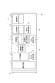
図1は、本発明の一実施の形態における光源駆動装置の構成を示す図である。 FIG. 1 is a diagram showing a configuration of a light source driving device according to an embodiment of the present invention.
図1を参照して、光源駆動装置1aは、たとえばLEDドライバーと呼ばれるものであり、DALIを用いた入力信号(DALI信号)に基づいて、AC電源2から供給された交流電圧ACを用いて光源12を駆動する。光源12は、LEDモジュール12aおよび12b(第1および第2の光源の一例)を含んでいる。光源駆動装置1aは、1次側領域51と、2次側領域52と、整流回路3と、PFC回路4(非絶縁型力率改善回路の一例)と、絶縁型コンバーター5と、非絶縁型補助電源6と、DALI通信回路7と、第1の制御回路8aと、第2の制御回路8bと、絶縁型双方向回路9と、非絶縁型コンバーター11とを備えている。非絶縁型コンバーター11は、2台の非絶縁型コンバーター11aおよび11bを含んでいる。
Referring to FIG. 1, a light source driving device 1a is called, for example, an LED driver, and uses an AC voltage AC supplied from an
1次側領域51および2次側領域52は、互いに絶縁されている。整流回路3、PFC回路4、非絶縁型補助電源6、および第1の制御回路8aの各々は、1次側領域51に配置されている。第2の制御回路8b、ならびに非絶縁型コンバーター11aおよび11bの各々は、2次側領域52に配置されている。絶縁型コンバーター5、DALI通信回路7、および絶縁型双方向回路9の各々は、1次側領域51と2次側領域52とを絶縁した状態で、1次側領域51と2次側領域52とに跨がって配置されている。
The
整流回路3は、AC電源2からの交流電圧ACを全波整流することにより直流電圧DC1を生成する。
The
PFC回路4は、交流電圧ACの波形と整流回路3に入力される電流波形とが略相似形になるように制御することにより、交流電圧ACの力率を向上する。PFC回路4は、整流回路3から入力された直流電圧DC1を、異なる電圧(通常は、直流電圧DC1よりも高い電圧)の直流電圧DC2に変換する。PFC回路4の入力と出力とは、PFC回路4がオフの場合にも電気的に遮断されない。このため、PFC回路4がオフの場合にもPFC回路4を経由して電力を取りだすことが可能である。言い換えれば、PFC回路4は、オンの場合には直流電圧DC2を出力し、オフの場合には未変換の直流電圧DC1をそのまま出力する。PFC回路4は、直流電圧DC1またはDC2を絶縁型コンバーター5および非絶縁型補助電源6の各々に出力する。
The
非絶縁型補助電源6は、PFC回路4から入力された直流電圧DC1またはDC2を一定電圧の直流電圧DC5に変換する。非絶縁型補助電源6は、変換後の直流電圧DC5をDALI通信回路7と第1の制御回路8aとの各々に供給する。非絶縁型補助電源6による直流電圧DC5の供給は、PFC回路4のオンオフに関わらずに行われる。DALI通信回路7および第1の制御回路8aの各々は、非絶縁型補助電源6から供給された直流電圧DC5によって駆動する。
The non-insulated
DALI通信回路7は、光源駆動装置1aに接続された外部機器(たとえばマスターCPU(Central Processing Unit)などの操作装置)から送信されたDALI入力信号Sadをシリアル信号SRに変換する。DALI入力信号Sadは、2つの信号線間(D+およびD−)の電位差を指標する信号(すなわち、差動信号)である。高レベル(Hレベル)側の信号線は、たとえば9.5V〜22.5Vの電圧変動幅を有しており、低レベル(Lレベル)側の信号線は、たとえば−6.5V〜6.5Vの電圧変動幅を有している。
The
第1の制御回路8aは、たとえばマイコンで構成されており、入力電圧の仕様はたとえば5Vである。このため、DALI通信回路7は、広い電圧幅をもつDALI入力信号Sadを、第1の制御回路8aの入力電圧の仕様(5V以下)に対応した信号に変換する機能と、差動信号であるDALI入力信号Sadを極性のないシリアル信号SRに変換する機能とを有している。また、DALI入力信号Sadの送信元である外部機器と、第1の制御回路8aとは電気的に絶縁されている必要がある。このため、DALI通信回路7は、DALI入力信号Sadの送信元である外部機器と、第1の制御回路8aとを電気的に絶縁する機能を有している。DALI通信回路7は、たとえばアナログ回路によって構成されており、フォトカプラーなどを用いて構成されている。なお、通信の制御プロトコルがDALIではない制御プロトコルでもかまわない。その場合は、その通信の制御プロトコルに基づいた入力信号Sadが通信回路7によってシリアル信号SRに変換される構成になっていればよい。
The
DALI入力信号SadおよびDALI出力信号Sotの入出力端子は、図1では2次側領域52に配置されている。上述のようにDALI通信回路7は、DALI入力信号Sadの送信元である外部機器と、第1の制御回路8aとを電気的に絶縁する機能を有している。このため、DALI入力信号SadおよびDALI出力信号Sotの入出力端子は、1次側領域51に配置されていてもよい。なお、通信制御方式はDALIに限定されるものではなく、入出力端子を別々に分けることで、入力端子と出力端子とを設けてもよい。図1および後述する図2では、便宜上、入力端子と出力端子とを別々に示している。
The input / output terminals of the DALI input signal Sad and the DALI output signal Sot are arranged in the
第1の制御回路8aは、DALI通信制御機能と、オンオフ制御機能とを有している。第1の制御回路8aは、DALI通信回路7から入力されたシリアル信号SRに基づいて制御信号OF1を生成し、PFC回路4に送信する。これにより、第1の制御回路8aはPFC回路4のオンオフを制御する。第1の制御回路8aは、シリアル信号SRに基づいて制御信号OF2を生成し、絶縁型コンバーター5に送信する。これにより、第1の制御回路8aは絶縁型コンバーター5のオンオフを制御する。PFC回路4および絶縁型コンバーター5がオフの場合には、絶縁型コンバーター5よりも下流側に接続された全ての電子部品は動作を停止し、光源12は消灯する。
The
第1の制御回路8aは、第1の通信信号SN1を生成する。第1の通信信号SN1は、第2の制御回路8bへの指示信号である調光制御指示信号または調色制御指示信号を含んでいる。調光制御指示信号は、光源12を調光する信号である。調色制御指示信号は、光源12を調色する信号である。第1の制御回路8aは、第1の通信信号SN1を、絶縁型双方向回路9を通じて第2の制御回路8bに送信する。
The
絶縁型コンバーター5は、PFC回路4から入力された直流電圧DC2を、直流電圧DC2とは異なる電圧の直流電圧DC3に変換する。絶縁型コンバーター5は、変換後の直流電圧DC3を非絶縁型コンバーター11aおよび11bの各々に出力する。なお、PFC回路4が制御信号OF1によってオフに制御されている時には、同時に絶縁型コンバーター5も制御信号OF2によってオフに制御されている。PFC回路4がオフに制御されている時には、直流電圧DC1がPFC回路4から絶縁型コンバーター5に出力されるが、絶縁型コンバーター5はオフに制御されていることから、絶縁型コンバーター5は直流電圧DC1を直流電圧DC3に変換しない。絶縁型コンバーター5は、変換後の直流電圧DC3を第2の制御回路8bに供給する。第2の制御回路8bは、絶縁型コンバーター5から供給された直流電圧DC3によって駆動する。絶縁型コンバーター5は絶縁トランスを含んでいるため、その入力と出力とは電気的に絶縁されている。
The insulating
非絶縁型コンバーター11aは、絶縁型コンバーター5から入力された直流電圧DC3を、調光制御指示信号または調色制御指示信号に基づいた直流電流DC4aに変換し、変換後の直流電流DC4aをLEDモジュール12aに供給する。非絶縁型コンバーター11bは、絶縁型コンバーター5から入力された直流電圧DC3を、調光制御指示信号または調色制御指示信号に基づいた直流電流DC4bに変換し、変換後の直流電流DC4bをLEDモジュール12bに供給する。なお、非絶縁型コンバーター11aおよび11bは、異常状態検出回路を備えており、LEDモジュール12aおよび12bが異常状態にあるか否かを監視している。各々の異常状態検出回路は、LEDモジュール12aおよび12bの異常状態を検出した場合には、異常状態であることを第2の制御回路8bに送信するとともに、第2の制御回路8bが非絶縁型コンバーター11aおよび11bを停止させるように制御する。また、非絶縁型コンバーター11aおよび11bが保護回路を備えている構成であっても構わない。その場合、LEDモジュール12aおよび12bの異常によって保護回路が非絶縁型コンバーター11aおよび11bを停止させるように制御するとともに、保護回路が動作したことを第2の制御回路8bに送信する。
The
第2の制御回路8bは、光源12の調光または調色制御をする機能と、光源12の故障などの異常状態を監視する機能とを有している。第2の制御回路8bは、絶縁型双方向回路9を通じて第1の制御回路8aから入力された第1の通信信号SN1に基づいて、非絶縁型コンバーター11aおよび11bの各々を制御する。これにより、第2の制御回路8bは光源12を調光または調色する。第2の制御回路8bは、非絶縁型コンバーター11を監視することによって、光源12の点灯状態を示す(異常状態検出回路の監視結果より光源12が正しく駆動されているか否かを示す)第2の通信信号SN2を生成する。第2の制御回路8bは、第2の通信信号SN2を、絶縁型双方向回路9を通じて第1の制御回路8aに送信する。
The
第1の制御回路8aは、絶縁型双方向回路9を通じて第2の制御回路8bから受信した第2の通信信号SN2を、DALI通信回路7へ送信する。DALI通信回路7は、第1の制御回路8aから受信した第2の通信信号SN2に基づく情報を、DALIを用いた出力信号であるDALI出力信号Sotとして光源駆動装置1aの外部へ出力する。これにより、光源駆動装置の外部機器(操作装置など)と光源駆動装置との間の双方向通信が可能になる。なお、通信の制御プロトコルがDALIではない制御プロトコルの場合も同様に、通信回路7が、第1の制御回路8aから受信した第2の通信信号SN2に基づく情報を、適当な制御プロトコルを用いた出力信号Sotとして光源駆動装置1aの外部へ出力させればよい。
The
DALI出力信号Sotは、たとえば、光源12のオンオフの状態、光源12の輝度、光源12の色、または光源12の点灯状態(光源12が正しく駆動されているか否かを示す)などを示すものである。
The DALI output signal Sot indicates, for example, the on / off state of the
絶縁型双方向回路9は、第1の制御回路8aと第2の制御回路8bとの双方向通信を可能にする。絶縁型双方向回路9は、第1の制御回路8aから第2の制御回路8bへの第1の通信信号SN1の入力を仲介し、第2の制御回路8bから第1の制御回路8aへの第2の通信信号SN2の入力を仲介する。絶縁型双方向回路9は、たとえばフォトカプラーなどを用いて構成される。
The insulated
なお、光源12を構成する光源(LEDモジュール)の数は任意である。非絶縁型コンバーター11に含まれる非絶縁型コンバーターの数や構成は、電力の供給先となるLEDモジュールの数や構成によって変更される。
Note that the number of light sources (LED modules) constituting the
たとえば、光源12が、色温度が異なる2台のLEDモジュール12aおよび12bを含んでいる場合には、本実施の形態のように、非絶縁型コンバーター11は2台の非絶縁型コンバーター11aおよび11bによって構成されてもよいし、次に説明する変形例のように、非絶縁型コンバーター11は1台の非絶縁型コンバーターによって構成されてもよい。また、光源12が、1つの色温度を有する1台または複数台のモジュールを含んでいる場合には、非絶縁型コンバーター11は1台の非絶縁型コンバーターによって構成されてもよい。その他、光源12の消費電力が大きい場合には、非絶縁型コンバーター11が複数台の非絶縁型コンバーターによって構成されてもよい。
For example, when the
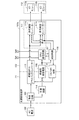
図2は、本発明の一実施の形態における光源駆動装置の変形例の構成を示す図である。 FIG. 2 is a diagram showing a configuration of a modification of the light source driving device according to the embodiment of the present invention.
図2を参照して、本変形例の光源駆動装置1bでは、非絶縁型コンバーター11は1台の非絶縁型コンバーター11bによって構成されている。絶縁型コンバーター5は、変換後の直流電圧DC3をLEDモジュール12a、非絶縁型コンバーター11、および第2の制御回路8bの各々に供給する。絶縁型コンバーター5は、LEDモジュール12aに対して直流電圧DC3を直接供給するので、直流電圧DC3は、LEDモジュール12aに流す直流電流DC4aに応じた大きさに設定される。非絶縁型コンバーター11bは、絶縁型コンバーター5から入力された直流電圧DC3を、調光制御指示信号または調色制御指示信号に基づいた直流電流(直流電圧)DC4bに変換し、変換して得られた直流電流DC4bをLEDモジュール12bに供給する。
With reference to FIG. 2, in the light source drive device 1b of this modification, the
本実施の形態における光源駆動装置1aおよび1bでは、非絶縁型補助電源6が1次側領域51に配置されている。また、制御回路が、1次側領域51に配置される第1の制御回路8aと、2次側領域52に配置される第2の制御回路8bとに分けられおり、第1の制御回路8aと第2の制御回路8bとの双方向の通信を可能にするために、絶縁型双方向回路9が設けられている。さらに、DALI通信回路7が1次側領域51と2次側領域52とに跨がって配置されている。
In the light source driving devices 1 a and 1 b in the present embodiment, the non-insulated
本実施の形態によれば、プリント回路基板の短手方向の長さを小さくことができ、光源駆動装置の小型化を図ることができる。また、電子部品の配置の自由度を高めることができる。 According to the present embodiment, the length of the printed circuit board in the short direction can be reduced, and the light source driving device can be downsized. Moreover, the freedom degree of arrangement | positioning of an electronic component can be raised.
図3は、本発明の一実施の形態における光源駆動装置を構成する各電子部品を、プリント回路基板上に実装した場合のレイアウトの一例を示す図である。 FIG. 3 is a diagram illustrating an example of a layout when each electronic component constituting the light source driving device according to the embodiment of the present invention is mounted on a printed circuit board.
図3を参照して、光源駆動装置1aを構成する各電子部品が、矩形状のプリント回路基板60(基板の一例)上に実装されている。プリント回路基板60の短手方向の長さWをできるだけ小さくすることを目的として、光源駆動装置1aを構成する各電子部品は、プリント回路基板60の長手方向に1個ずつ並べて配置されている。1次側領域51と2次側領域52との境界線は、プリント回路基板60の短手方向に直線状に延在している。このため、1次側領域51と2次側領域52とに跨がって配置される絶縁型コンバーター5、DAL通信回路7、および絶縁型双方向回路9は、プリント回路基板60の短手方向に(境界線に沿って)並べて配置されている。絶縁型コンバーター5、非絶縁型補助電源6、および非絶縁型コンバーター11などの電子部品は、絶縁トランスを含んでいるため、絶縁トランスを含まない他の電子部品(整流回路3を除く)に比べてサイズが大きい。
With reference to FIG. 3, each electronic component which comprises the light source drive device 1a is mounted on the rectangular printed circuit board 60 (an example of a board | substrate). For the purpose of reducing the length W in the short direction of the printed
本実施の形態では、絶縁型補助電源106の代わりに非絶縁型補助電源6を用いているので、補助電源を1次側領域51と2次側領域52とに跨がって配置する必要がなくなる。光源駆動装置1aおよび1bにおいて、1次側領域51と2次側領域52とに跨がって配置される部品は、絶縁型コンバーター5、DALI通信回路7、および絶縁型双方向回路9となる。このうち、DALI通信回路7および絶縁型双方向回路9は、絶縁トランスを含んでいないので、DALI通信回路7および絶縁型双方向回路9を配置することによる長さWの増加はわずかである。言い換えれば、光源駆動装置1aおよび1bの短手方向の長さWは、主に絶縁型コンバーター5が備える絶縁トランスの大きさで決まる。その結果、光源駆動装置の短手方向の長さWを短くすることができ、光源駆動装置の小型化を図ることができる。加えて、光源駆動装置の設計の自由度を高めることができ、ひいては照明器具の設計の自由度も高めることができる。
In the present embodiment, since the non-insulated
また、DALI通信回路7が1次側領域51と2次側領域52とに跨がって配置されるので、DALI入力信号SadおよびDALI出力信号Sotの入出力端子を1次側領域51に配置することも、2次側領域52に配置することもできる。その結果、光源駆動装置の外部との配線であるDALI通信配線(DALI入力信号SadおよびDALI出力信号Sotの入出力端子と接続する配線)を1次側領域51に配置することも、2次側領域52に配置することもでき、回路の設計の自由度が上がる。
Further, since the
特に、DALI入力信号SadおよびDALI出力信号Sotの入出力端子を2次側領域52に配置した場合には、1次側領域51にある光源駆動装置の外部との配線を減らすことができる(AC電源2との間の接続線のみにすることができる)。その結果、以下に説明するように、プリント回路基板160の短手方向の長さWを短くし易くなる。
In particular, when the input / output terminals of the DALI input signal Sad and the DALI output signal Sot are arranged in the
整流回路は、AC電源から入力される交流電圧ACが2つの導線(L相/N相)を介して入力される。2つの導線間の距離や、2つの導線の各々と他の部品との距離は、安全規格で要求される絶縁距離以上である必要がある。一般に、整流回路に要求される絶縁距離は、整流回路の出力側の部品に要求される絶縁距離よりも大きい(ただし、1次側領域と2次側領域との間に要求される絶縁距離を除く)。 In the rectifier circuit, an AC voltage AC input from an AC power supply is input via two conductive wires (L phase / N phase). The distance between the two conductors and the distance between each of the two conductors and other parts must be equal to or greater than the insulation distance required by the safety standard. In general, the insulation distance required for the rectifier circuit is larger than the insulation distance required for the components on the output side of the rectifier circuit (however, the insulation distance required between the primary side region and the secondary side region is except).
また、交流電圧ACの定格電圧値の大きさに応じて要求される絶縁距離は大きくなり、それによって整流回路自身のサイズ(専有面積)が大きくなる。光源駆動装置がアース線或いはアース機構を備える場合、整流回路3には上述の2つの導線の他にアース線も接続される。その結果、アースの導線に対する絶縁距離も必要となり整流回路のサイズはさらに大きくなる。
Further, the insulation distance required in accordance with the magnitude of the rated voltage value of the AC voltage AC increases, thereby increasing the size (occupied area) of the rectifier circuit itself. When the light source driving device includes a ground wire or a ground mechanism, the
図4は、参考例における光源駆動装置を構成する各電子部品を、プリント回路基板上に実装した場合のレイアウトの一例を示す図である。 FIG. 4 is a diagram showing an example of a layout when each electronic component constituting the light source driving device in the reference example is mounted on a printed circuit board.
図4を参照して、参考例のように、DALI通信配線を1次側領域151に配置した場合(プリント回路基板160の短手方向に沿って延在する1次側領域151の端面から、交流電圧ACおよびDALI入力信号Sadを入力し、DALI出力信号Sotを出力する場合)を想定する。この場合、整流回路103およびDALI通信回路107は、プリント回路基板160の短手方向に並べて配置される。その結果、整流回路103およびDALI通信回路107が配置される部分の長さが、プリント回路基板160の短手方向の長さWを短くすることのネックになり易い。本実施の形態のようにDALI通信配線を2次側領域152に配置した場合には、参考例のような事態を回避することができる。
Referring to FIG. 4, when the DALI communication wiring is arranged in the
なお、光源駆動装置を構成する電子部品が実装される基板は、矩形状のものに限られるものではない。1次側領域と2次側領域との境界線は直線状のものに限られるものではない。1次側領域と2次側領域との境界線が直線状でない場合にも、1次側領域と2次側領域との境界線上に配置される電子部品の数が少なくなるので、1次側領域と2次側領域との境界線の長さを短くすることができる、その結果、光源駆動装置の小型化を図ることができ、光源駆動装置の設計の自由度を高めることができる。 In addition, the board | substrate with which the electronic component which comprises a light source drive device is mounted is not restricted to a rectangular shape. The boundary line between the primary side region and the secondary side region is not limited to a straight line. Even when the boundary line between the primary side region and the secondary side region is not linear, the number of electronic components arranged on the boundary line between the primary side region and the secondary side region is reduced. The length of the boundary line between the region and the secondary region can be shortened. As a result, the light source driving device can be reduced in size, and the degree of freedom in designing the light source driving device can be increased.
上述の実施の形態および変形例は、すべての点で例示であって制限的なものではないと考えられるべきである。本発明の範囲は上記した説明ではなくて特許請求の範囲によって示され、特許請求の範囲と均等の意味および範囲内でのすべての変更が含まれることが意図される。 The above-described embodiments and modifications should be considered as illustrative in all points and not restrictive. The scope of the present invention is defined by the terms of the claims, rather than the description above, and is intended to include any modifications within the scope and meaning equivalent to the terms of the claims.
1a,1b,101a,101b 光源駆動装置
2,102 AC(Alternating Current)電源(交流電源)
3,103 整流回路
4,104 PFC(Power Factor Correction)回路(非絶縁型力率改善回路)
5,105 絶縁型コンバーター
6 非絶縁型補助電源
7,107 DALI(Digital Addressable Lighting Interface)通信回路(通信回路)
8a 第1の制御回路
8b 第2の制御回路
9 絶縁型双方向回路
11,11a,11b,111,111a,111b 非絶縁型コンバーター
12,112 光源
12a,12b,112a,112b LED(Light Emitting Diode)モジュール
51,151 1次側領域
52,152 2次側領域
60,160 プリント回路基板
106 絶縁型補助電源
108 制御回路
110 ON/OFF回路
113 絶縁型PFCフライバックコンバーター
114 平滑回路
AC 交流電圧
DC1,DC2,DC3,DC5 直流電圧
DC4a,DC4b 直流電流
OF1,OF2 制御信号
Sad DALI入力信号(入力信号)
Sot DALI出力信号(出力信号)
SR シリアル信号
SN1 第1の通信信号
SN2 第2の通信信号
1a, 1b, 101a, 101b Light source driving device 2,102 AC (Alternating Current) power source (AC power source)
3,103 Rectifier circuit 4,104 PFC (Power Factor Correction) circuit (non-insulated power factor correction circuit)
5,105
8a
Sot DALI output signal (output signal)
SR serial signal SN1 first communication signal SN2 second communication signal
Claims (11)
互いに絶縁された1次側領域および2次側領域と、
前記1次側領域と前記2次側領域とに跨がって配置され、前記入力信号をシリアル信号に変換する通信回路と、
前記1次側領域に配置され、前記通信回路から入力された前記シリアル信号に基づいて前記光源のオンオフを制御し、前記光源を調光または調色するための第1の通信信号を生成する第1の制御回路と、
前記1次側領域に配置され、前記交流電源から供給された交流電圧を変換して得られた直流電圧を、前記通信回路および前記第1の制御回路の各々に供給する非絶縁型補助電源と、
前記2次側領域に配置され、前記第1の制御回路から入力された前記第1の通信信号に基づいて前記光源を調光または調色し、前記光源の点灯状態を示す第2の通信信号を生成する第2の制御回路と、
前記1次側領域と前記2次側領域とに跨がって配置され、前記1次側領域と前記2次側領域とを絶縁した状態で、前記第1の制御回路から前記第2の制御回路への前記第1の通信信号の入力を仲介し、前記第2の制御回路から前記第1の制御回路への前記第2の通信信号の入力を仲介する絶縁型双方向回路とを備えた、光源駆動装置。 A light source driving device that drives the light source using an AC voltage supplied from an AC power source based on an input signal using a control protocol for controlling the operation of the light source,
A primary region and a secondary region that are insulated from each other;
A communication circuit that is arranged across the primary side region and the secondary side region and converts the input signal into a serial signal;
A first communication signal that is disposed in the primary side region and controls on / off of the light source based on the serial signal input from the communication circuit and generates a first communication signal for dimming or toning the light source. 1 control circuit;
A non-insulated auxiliary power source arranged in the primary region and supplying a DC voltage obtained by converting an AC voltage supplied from the AC power source to each of the communication circuit and the first control circuit; ,
A second communication signal that is disposed in the secondary region and that dimmes or adjusts the light source based on the first communication signal input from the first control circuit and indicates a lighting state of the light source. A second control circuit for generating
The second control is performed from the first control circuit in a state in which the primary side region and the secondary side region are disposed across the primary side region and the secondary side region, and the primary side region and the secondary side region are insulated. An insulating bidirectional circuit that mediates input of the first communication signal to the circuit and mediates input of the second communication signal from the second control circuit to the first control circuit. , Light source driving device.
前記通信回路は、前記第1の制御回路から入力された前記第2の通信信号に基づく情報を、前記制御プロトコルを用いた出力信号として前記光源駆動装置の外部へ出力する、請求項1に記載の光源駆動装置。 The control protocol is DALI (Digital Addressable Lighting Interface),
The said communication circuit outputs the information based on the said 2nd communication signal input from the said 1st control circuit to the exterior of the said light source drive device as an output signal using the said control protocol. Light source driving device.
前記入出力端子は前記2次側領域に配置される、請求項1または2に記載の光源駆動装置。 The communication circuit includes an input / output terminal that inputs the input signal and outputs an output signal using the control protocol to the outside of the light source driving device,
The light source driving device according to claim 1, wherein the input / output terminal is disposed in the secondary region .
前記2次側領域に配置され、前記絶縁型コンバーターにより変換された直流電圧を、前記光源に供給する直流電流に変換する非絶縁型コンバーターとをさらに備え、
前記第1の制御回路は、前記絶縁型コンバーターのオンオフを制御する、請求項1〜3のいずれか一項に記載の光源駆動装置。 An isolated converter that is arranged across the primary side region and the secondary side region and converts a DC voltage obtained by converting an AC voltage supplied from the AC power source into a DC voltage of a different voltage. When,
A non-insulated converter that is disposed in the secondary region and converts a DC voltage converted by the isolated converter into a DC current supplied to the light source;
The light source driving device according to claim 1, wherein the first control circuit controls on / off of the insulating converter.
前記整流回路から入力された直流電圧を、前記整流回路から出力された直流電圧とは異なる電圧の直流電圧に変換する非絶縁型力率改善回路とをさらに備え、
前記第1の制御回路は、前記非絶縁型力率改善回路のオンオフをさらに制御し、
前記絶縁型コンバーターは、前記非絶縁型力率改善回路から入力された直流電圧を、異なる電圧の直流電圧に変換し、
前記非絶縁型補助電源は、前記非絶縁型力率改善回路から入力された直流電圧を、前記通信回路および前記第1の制御回路の各々に供給する、請求項4に記載の光源駆動装置。 A rectifier circuit that generates a DC voltage by full-wave rectifying the AC voltage supplied from the AC power supply;
A non-insulated power factor correction circuit that converts the DC voltage input from the rectifier circuit into a DC voltage different from the DC voltage output from the rectifier circuit;
The first control circuit further controls on / off of the non-insulated power factor correction circuit,
The isolated converter converts the DC voltage input from the non-insulated power factor correction circuit into a DC voltage of a different voltage,
The light source driving device according to claim 4, wherein the non-isolated auxiliary power supply supplies a DC voltage input from the non-isolated power factor correction circuit to each of the communication circuit and the first control circuit.
前記非絶縁型コンバーターは、
前記絶縁型コンバーターから入力された直流電圧を第1の直流電流に変換し、前記第1の直流電流を前記第1の光源に供給する第1の非絶縁型コンバーターと、
前記絶縁型コンバーターから入力された直流電圧を第2の直流電流に変換し、前記第2の直流電流を前記第2の光源に供給する第2の非絶縁型コンバーターとを含む、請求項4〜6のいずれか一項に記載の光源駆動装置。 The light source includes a first light source and a second light source having different color temperatures,
The non-insulated converter is
A first non-insulated converter that converts a DC voltage input from the isolated converter into a first DC current and supplies the first DC current to the first light source;
5. A second non-insulated converter that converts a DC voltage input from the isolated converter into a second DC current and supplies the second DC current to the second light source. The light source driving device according to claim 6.
前記絶縁型コンバーターは、前記絶縁型コンバーターが変換して得た直流電圧を前記第1の光源に直接供給し、
前記非絶縁型コンバーターは、前記非絶縁型コンバーターが変換して得た直流電圧を前記第2の光源に供給する、請求項4〜6のいずれか一項に記載の光源駆動装置。 The light source includes a first light source and a second light source having different color temperatures,
The isolated converter directly supplies a DC voltage obtained by the conversion of the isolated converter to the first light source,
The light source driving device according to any one of claims 4 to 6, wherein the non-insulated converter supplies a DC voltage obtained by conversion by the non-insulated converter to the second light source.
前記通信回路、前記絶縁型双方向回路、および前記絶縁型コンバーターの各々は、前記基板上において前記基板の短手方向に並べて配置される、請求項4〜8のいずれか一項に記載の光源駆動装置。 Further comprising a rectangular substrate in which the primary side region and the secondary side region are formed,
The light source according to any one of claims 4 to 8, wherein each of the communication circuit, the insulated bidirectional circuit, and the insulated converter is arranged side by side in the lateral direction of the substrate on the substrate. Drive device.
前記光源とを備えた、照明装置。 The light source driving device according to any one of claims 1 to 10,
An illumination device comprising the light source.
Priority Applications (1)
| Application Number | Priority Date | Filing Date | Title |
|---|---|---|---|
| JP2015069197A JP6185952B2 (en) | 2015-03-30 | 2015-03-30 | LIGHT SOURCE DRIVING DEVICE AND LIGHTING DEVICE HAVING THE SAME |
Applications Claiming Priority (1)
| Application Number | Priority Date | Filing Date | Title |
|---|---|---|---|
| JP2015069197A JP6185952B2 (en) | 2015-03-30 | 2015-03-30 | LIGHT SOURCE DRIVING DEVICE AND LIGHTING DEVICE HAVING THE SAME |
Publications (3)
| Publication Number | Publication Date |
|---|---|
| JP2016189282A JP2016189282A (en) | 2016-11-04 |
| JP2016189282A5 JP2016189282A5 (en) | 2017-03-09 |
| JP6185952B2 true JP6185952B2 (en) | 2017-08-23 |
Family
ID=57240580
Family Applications (1)
| Application Number | Title | Priority Date | Filing Date |
|---|---|---|---|
| JP2015069197A Active JP6185952B2 (en) | 2015-03-30 | 2015-03-30 | LIGHT SOURCE DRIVING DEVICE AND LIGHTING DEVICE HAVING THE SAME |
Country Status (1)
| Country | Link |
|---|---|
| JP (1) | JP6185952B2 (en) |
Families Citing this family (1)
| Publication number | Priority date | Publication date | Assignee | Title |
|---|---|---|---|---|
| JP6594357B2 (en) * | 2017-01-30 | 2019-10-23 | ミネベアミツミ株式会社 | Light source driving device and lighting device |
Family Cites Families (2)
| Publication number | Priority date | Publication date | Assignee | Title |
|---|---|---|---|---|
| WO2010031169A1 (en) * | 2008-09-18 | 2010-03-25 | E Craftsmen Corporation | Configurable led driver/dimmer for solid state lighting applications |
| JP5947060B2 (en) * | 2012-02-29 | 2016-07-06 | ミネベア株式会社 | LED power supply |
-
2015
- 2015-03-30 JP JP2015069197A patent/JP6185952B2/en active Active
Also Published As
| Publication number | Publication date |
|---|---|
| JP2016189282A (en) | 2016-11-04 |
Similar Documents
| Publication | Publication Date | Title |
|---|---|---|
| JP6028283B2 (en) | System and apparatus for driving a plurality of high power LED units | |
| JP5842100B2 (en) | Lighting device for visible light communication and visible light communication system using the same | |
| JP5132749B2 (en) | Light source lighting device and lighting fixture | |
| JP5163590B2 (en) | LED lighting device and marker lamp system | |
| CN102740546B (en) | Luminaire | |
| US8896222B2 (en) | Power supply device and luminaire | |
| JP5896144B2 (en) | Power supply device and lighting device | |
| KR101353218B1 (en) | Illumination device | |
| US9648689B2 (en) | Drive unit for a lighting element and operating method therefor | |
| EP2699060A2 (en) | Luminaire | |
| CN109309985B (en) | Lighting system | |
| JP6185952B2 (en) | LIGHT SOURCE DRIVING DEVICE AND LIGHTING DEVICE HAVING THE SAME | |
| JP2016115433A (en) | Light source drive device and lighting system including the same | |
| JP6614315B2 (en) | Illumination lamp and illumination device | |
| JP2010067831A (en) | Power source device and luminaire | |
| JP2011113834A (en) | Lighting system | |
| JP5807196B2 (en) | lighting equipment | |
| KR101357678B1 (en) | Power Supply Apparatus For Navigation Light | |
| JP5447497B2 (en) | Light source lighting device and lighting device | |
| EP3089556B1 (en) | Illumination lamp, illumination apparatus, and illumination control circuit | |
| JP6101941B2 (en) | Dimmable LED lighting system | |
| JP2005285369A (en) | Power source device and illumination device including the same | |
| JP7303489B2 (en) | lighting equipment | |
| JP6145307B2 (en) | Lighting system | |
| JP2022187764A (en) | Lighting system and power supply device |
Legal Events
| Date | Code | Title | Description |
|---|---|---|---|
| A621 | Written request for application examination |
Free format text: JAPANESE INTERMEDIATE CODE: A621 Effective date: 20161007 |
|
| A521 | Written amendment |
Free format text: JAPANESE INTERMEDIATE CODE: A523 Effective date: 20170131 |
|
| A977 | Report on retrieval |
Free format text: JAPANESE INTERMEDIATE CODE: A971007 Effective date: 20170627 |
|
| TRDD | Decision of grant or rejection written | ||
| A01 | Written decision to grant a patent or to grant a registration (utility model) |
Free format text: JAPANESE INTERMEDIATE CODE: A01 Effective date: 20170704 |
|
| A61 | First payment of annual fees (during grant procedure) |
Free format text: JAPANESE INTERMEDIATE CODE: A61 Effective date: 20170728 |
|
| R150 | Certificate of patent or registration of utility model |
Ref document number: 6185952 Country of ref document: JP Free format text: JAPANESE INTERMEDIATE CODE: R150 |
|
| R250 | Receipt of annual fees |
Free format text: JAPANESE INTERMEDIATE CODE: R250 |