JP6184535B2 - Image processing apparatus, control method thereof, and computer program. - Google Patents
Image processing apparatus, control method thereof, and computer program. Download PDFInfo
- Publication number
- JP6184535B2 JP6184535B2 JP2016007425A JP2016007425A JP6184535B2 JP 6184535 B2 JP6184535 B2 JP 6184535B2 JP 2016007425 A JP2016007425 A JP 2016007425A JP 2016007425 A JP2016007425 A JP 2016007425A JP 6184535 B2 JP6184535 B2 JP 6184535B2
- Authority
- JP
- Japan
- Prior art keywords
- moving image
- jam
- sensor
- conveyance path
- forming apparatus
- Prior art date
- Legal status (The legal status is an assumption and is not a legal conclusion. Google has not performed a legal analysis and makes no representation as to the accuracy of the status listed.)
- Active
Links
Images


Classifications
-
- G—PHYSICS
- G03—PHOTOGRAPHY; CINEMATOGRAPHY; ANALOGOUS TECHNIQUES USING WAVES OTHER THAN OPTICAL WAVES; ELECTROGRAPHY; HOLOGRAPHY
- G03G—ELECTROGRAPHY; ELECTROPHOTOGRAPHY; MAGNETOGRAPHY
- G03G15/00—Apparatus for electrographic processes using a charge pattern
- G03G15/50—Machine control of apparatus for electrographic processes using a charge pattern, e.g. regulating differents parts of the machine, multimode copiers, microprocessor control
- G03G15/5016—User-machine interface; Display panels; Control console
-
- B—PERFORMING OPERATIONS; TRANSPORTING
- B41—PRINTING; LINING MACHINES; TYPEWRITERS; STAMPS
- B41J—TYPEWRITERS; SELECTIVE PRINTING MECHANISMS, i.e. MECHANISMS PRINTING OTHERWISE THAN FROM A FORME; CORRECTION OF TYPOGRAPHICAL ERRORS
- B41J11/00—Devices or arrangements of selective printing mechanisms, e.g. ink-jet printers or thermal printers, for supporting or handling copy material in sheet or web form
- B41J11/006—Means for preventing paper jams or for facilitating their removal
-
- H—ELECTRICITY
- H04—ELECTRIC COMMUNICATION TECHNIQUE
- H04N—PICTORIAL COMMUNICATION, e.g. TELEVISION
- H04N1/00—Scanning, transmission or reproduction of documents or the like, e.g. facsimile transmission; Details thereof
- H04N1/32—Circuits or arrangements for control or supervision between transmitter and receiver or between image input and image output device, e.g. between a still-image camera and its memory or between a still-image camera and a printer device
- H04N1/32609—Fault detection or counter-measures, e.g. original mis-positioned, shortage of paper
- H04N1/32646—Counter-measures
- H04N1/32651—Indicating or reporting
- H04N1/32657—Indicating or reporting locally
-
- B—PERFORMING OPERATIONS; TRANSPORTING
- B41—PRINTING; LINING MACHINES; TYPEWRITERS; STAMPS
- B41J—TYPEWRITERS; SELECTIVE PRINTING MECHANISMS, i.e. MECHANISMS PRINTING OTHERWISE THAN FROM A FORME; CORRECTION OF TYPOGRAPHICAL ERRORS
- B41J29/00—Details of, or accessories for, typewriters or selective printing mechanisms not otherwise provided for
- B41J29/54—Locking devices applied to printing mechanisms
- B41J29/58—Locking devices applied to printing mechanisms and automatically actuated
-
- G—PHYSICS
- G03—PHOTOGRAPHY; CINEMATOGRAPHY; ANALOGOUS TECHNIQUES USING WAVES OTHER THAN OPTICAL WAVES; ELECTROGRAPHY; HOLOGRAPHY
- G03G—ELECTROGRAPHY; ELECTROPHOTOGRAPHY; MAGNETOGRAPHY
- G03G15/00—Apparatus for electrographic processes using a charge pattern
- G03G15/50—Machine control of apparatus for electrographic processes using a charge pattern, e.g. regulating differents parts of the machine, multimode copiers, microprocessor control
- G03G15/5016—User-machine interface; Display panels; Control console
- G03G15/502—User-machine interface; Display panels; Control console relating to the structure of the control menu, e.g. pop-up menus, help screens
-
- G—PHYSICS
- G03—PHOTOGRAPHY; CINEMATOGRAPHY; ANALOGOUS TECHNIQUES USING WAVES OTHER THAN OPTICAL WAVES; ELECTROGRAPHY; HOLOGRAPHY
- G03G—ELECTROGRAPHY; ELECTROPHOTOGRAPHY; MAGNETOGRAPHY
- G03G15/00—Apparatus for electrographic processes using a charge pattern
- G03G15/50—Machine control of apparatus for electrographic processes using a charge pattern, e.g. regulating differents parts of the machine, multimode copiers, microprocessor control
- G03G15/5075—Remote control machines, e.g. by a host
-
- G—PHYSICS
- G03—PHOTOGRAPHY; CINEMATOGRAPHY; ANALOGOUS TECHNIQUES USING WAVES OTHER THAN OPTICAL WAVES; ELECTROGRAPHY; HOLOGRAPHY
- G03G—ELECTROGRAPHY; ELECTROPHOTOGRAPHY; MAGNETOGRAPHY
- G03G15/00—Apparatus for electrographic processes using a charge pattern
- G03G15/70—Detecting malfunctions relating to paper handling, e.g. jams
-
- G—PHYSICS
- G03—PHOTOGRAPHY; CINEMATOGRAPHY; ANALOGOUS TECHNIQUES USING WAVES OTHER THAN OPTICAL WAVES; ELECTROGRAPHY; HOLOGRAPHY
- G03G—ELECTROGRAPHY; ELECTROPHOTOGRAPHY; MAGNETOGRAPHY
- G03G21/00—Arrangements not provided for by groups G03G13/00 - G03G19/00, e.g. cleaning, elimination of residual charge
- G03G21/16—Mechanical means for facilitating the maintenance of the apparatus, e.g. modular arrangements
- G03G21/1604—Arrangement or disposition of the entire apparatus
- G03G21/1623—Means to access the interior of the apparatus
- G03G21/1633—Means to access the interior of the apparatus using doors or covers
-
- G—PHYSICS
- G03—PHOTOGRAPHY; CINEMATOGRAPHY; ANALOGOUS TECHNIQUES USING WAVES OTHER THAN OPTICAL WAVES; ELECTROGRAPHY; HOLOGRAPHY
- G03G—ELECTROGRAPHY; ELECTROPHOTOGRAPHY; MAGNETOGRAPHY
- G03G21/00—Arrangements not provided for by groups G03G13/00 - G03G19/00, e.g. cleaning, elimination of residual charge
- G03G21/16—Mechanical means for facilitating the maintenance of the apparatus, e.g. modular arrangements
- G03G21/1604—Arrangement or disposition of the entire apparatus
- G03G21/1623—Means to access the interior of the apparatus
- G03G21/1638—Means to access the interior of the apparatus directed to paper handling or jam treatment
-
- G—PHYSICS
- G08—SIGNALLING
- G08B—SIGNALLING OR CALLING SYSTEMS; ORDER TELEGRAPHS; ALARM SYSTEMS
- G08B5/00—Visible signalling systems, e.g. personal calling systems, remote indication of seats occupied
- G08B5/22—Visible signalling systems, e.g. personal calling systems, remote indication of seats occupied using electric transmission; using electromagnetic transmission
-
- H—ELECTRICITY
- H04—ELECTRIC COMMUNICATION TECHNIQUE
- H04N—PICTORIAL COMMUNICATION, e.g. TELEVISION
- H04N1/00—Scanning, transmission or reproduction of documents or the like, e.g. facsimile transmission; Details thereof
- H04N1/0035—User-machine interface; Control console
- H04N1/00405—Output means
- H04N1/0048—Indicating an illegal or impossible operation or selection to the user
-
- H—ELECTRICITY
- H04—ELECTRIC COMMUNICATION TECHNIQUE
- H04N—PICTORIAL COMMUNICATION, e.g. TELEVISION
- H04N1/00—Scanning, transmission or reproduction of documents or the like, e.g. facsimile transmission; Details thereof
- H04N1/00519—Constructional details not otherwise provided for, e.g. housings, covers
- H04N1/00551—Top covers or the like
- H04N1/00554—Latches or hinges therefor
-
- H—ELECTRICITY
- H04—ELECTRIC COMMUNICATION TECHNIQUE
- H04N—PICTORIAL COMMUNICATION, e.g. TELEVISION
- H04N1/00—Scanning, transmission or reproduction of documents or the like, e.g. facsimile transmission; Details thereof
- H04N1/00912—Arrangements for controlling a still picture apparatus or components thereof not otherwise provided for
- H04N1/00925—Inhibiting an operation
-
- H—ELECTRICITY
- H04—ELECTRIC COMMUNICATION TECHNIQUE
- H04N—PICTORIAL COMMUNICATION, e.g. TELEVISION
- H04N1/00—Scanning, transmission or reproduction of documents or the like, e.g. facsimile transmission; Details thereof
- H04N1/32—Circuits or arrangements for control or supervision between transmitter and receiver or between image input and image output device, e.g. between a still-image camera and its memory or between a still-image camera and a printer device
- H04N1/32609—Fault detection or counter-measures, e.g. original mis-positioned, shortage of paper
- H04N1/32625—Fault detection
- H04N1/3263—Fault detection of reading apparatus or transmitter, e.g. original jam
-
- G—PHYSICS
- G03—PHOTOGRAPHY; CINEMATOGRAPHY; ANALOGOUS TECHNIQUES USING WAVES OTHER THAN OPTICAL WAVES; ELECTROGRAPHY; HOLOGRAPHY
- G03G—ELECTROGRAPHY; ELECTROPHOTOGRAPHY; MAGNETOGRAPHY
- G03G15/00—Apparatus for electrographic processes using a charge pattern
- G03G15/50—Machine control of apparatus for electrographic processes using a charge pattern, e.g. regulating differents parts of the machine, multimode copiers, microprocessor control
- G03G15/5012—Priority interrupt; Job recovery, e.g. after jamming or malfunction
-
- G—PHYSICS
- G03—PHOTOGRAPHY; CINEMATOGRAPHY; ANALOGOUS TECHNIQUES USING WAVES OTHER THAN OPTICAL WAVES; ELECTROGRAPHY; HOLOGRAPHY
- G03G—ELECTROGRAPHY; ELECTROPHOTOGRAPHY; MAGNETOGRAPHY
- G03G2215/00—Apparatus for electrophotographic processes
- G03G2215/00025—Machine control, e.g. regulating different parts of the machine
- G03G2215/00109—Remote control of apparatus, e.g. by a host
-
- G—PHYSICS
- G03—PHOTOGRAPHY; CINEMATOGRAPHY; ANALOGOUS TECHNIQUES USING WAVES OTHER THAN OPTICAL WAVES; ELECTROGRAPHY; HOLOGRAPHY
- G03G—ELECTROGRAPHY; ELECTROPHOTOGRAPHY; MAGNETOGRAPHY
- G03G2221/00—Processes not provided for by group G03G2215/00, e.g. cleaning or residual charge elimination
- G03G2221/16—Mechanical means for facilitating the maintenance of the apparatus, e.g. modular arrangements and complete machine concepts
- G03G2221/1651—Mechanical means for facilitating the maintenance of the apparatus, e.g. modular arrangements and complete machine concepts for connecting the different parts
- G03G2221/1654—Locks and means for positioning or alignment
-
- G—PHYSICS
- G03—PHOTOGRAPHY; CINEMATOGRAPHY; ANALOGOUS TECHNIQUES USING WAVES OTHER THAN OPTICAL WAVES; ELECTROGRAPHY; HOLOGRAPHY
- G03G—ELECTROGRAPHY; ELECTROPHOTOGRAPHY; MAGNETOGRAPHY
- G03G2221/00—Processes not provided for by group G03G2215/00, e.g. cleaning or residual charge elimination
- G03G2221/16—Mechanical means for facilitating the maintenance of the apparatus, e.g. modular arrangements and complete machine concepts
- G03G2221/1672—Paper handling
- G03G2221/1675—Paper handling jam treatment
-
- H—ELECTRICITY
- H04—ELECTRIC COMMUNICATION TECHNIQUE
- H04N—PICTORIAL COMMUNICATION, e.g. TELEVISION
- H04N2201/00—Indexing scheme relating to scanning, transmission or reproduction of documents or the like, and to details thereof
- H04N2201/0077—Types of the still picture apparatus
- H04N2201/0082—Image hardcopy reproducer
-
- H—ELECTRICITY
- H04—ELECTRIC COMMUNICATION TECHNIQUE
- H04N—PICTORIAL COMMUNICATION, e.g. TELEVISION
- H04N2201/00—Indexing scheme relating to scanning, transmission or reproduction of documents or the like, and to details thereof
- H04N2201/32—Circuits or arrangements for control or supervision between transmitter and receiver or between image input and image output device, e.g. between a still-image camera and its memory or between a still-image camera and a printer device
- H04N2201/3201—Display, printing, storage or transmission of additional information, e.g. ID code, date and time or title
- H04N2201/3261—Display, printing, storage or transmission of additional information, e.g. ID code, date and time or title of multimedia information, e.g. a sound signal
- H04N2201/3267—Display, printing, storage or transmission of additional information, e.g. ID code, date and time or title of multimedia information, e.g. a sound signal of motion picture signals, e.g. video clip
Description
画像処理装置のメンテナンス手順の表示方法に関する。 The present invention relates to a method for displaying a maintenance procedure of an image processing apparatus.
従来から、ジャム解除やトナーカートリッジの交換、ホチキス針の補給などのメンテナンスの手順を、動画により提示する画像処理装置が提案されている(特許文献1)。これは、動画の表現性の高さや豊富な情報量により、ユーザが、より円滑にメンテナンスを実施できるようにすることを目的としている。 Conventionally, there has been proposed an image processing apparatus that presents maintenance procedures such as jam removal, toner cartridge replacement, and staple supply by moving images (Patent Document 1). This is intended to allow the user to perform maintenance more smoothly due to the high expressiveness of the moving image and the abundant amount of information.
画像処理装置の状態によっては、メンテナンス手順を実施する際に、ユーザに伝えるべき注意事項が存在する場合がある。例えば、ジャム紙の除去において、装置を誤って操作すると、ジャム紙が切断されてしまうので、それを防ぐために特定のカバーが開けられるのをロックする場合がある。このときに、ユーザがカバーのロックに気付かずに無理やり当該特定のカバーを開けようしてしまうと、装置の故障の原因になってしまう。 Depending on the state of the image processing apparatus, there are cases where there are precautions to be communicated to the user when performing the maintenance procedure. For example, when removing the jammed paper, if the apparatus is mistakenly operated, the jammed paper will be cut, and in order to prevent this, the opening of a specific cover may be locked. At this time, if the user forcibly opens the specific cover without noticing the lock of the cover, the apparatus may be damaged.
本発明は、所定のカバーが開状態の時にユーザにより引き出すことが可能な第1の搬送路と、前記第1の搬送路上を搬送された用紙が続いて搬送される第2の搬送路とに跨るようなジャムを検出した場合に発生する課題を解決することを目的とする。 The present invention provides a first conveyance path that can be pulled out by a user when a predetermined cover is in an open state, and a second conveyance path through which a sheet conveyed on the first conveyance path is subsequently conveyed. An object is to solve a problem that occurs when a jam that crosses over is detected.
上記課題を解決するために、本発明は、画像形成装置であって、用紙の搬送路であって、所定のカバーが開いているときにユーザにより引き出すことが可能な第1の搬送路と、前記第1の搬送路上で搬送された用紙が続いて搬送される第2の搬送路と、前記第1の搬送路上での用紙のジャムを検出する第1の検出手段と、前記第2の搬送路上での用紙のジャムを検出する第2の検出手段と、前記第1の検出手段と前記第2の検出手段との両方で用紙のジャムを検出した場合に、前記所定のカバーが開かないようロックするロック手段と、前記第1の検出手段または前記第2の検出手段により検出されたジャムを解消するために必要な作業を示す動画を表示する表示制御手段と、を有し、前記表示制御手段は、前記第1の検出手段と前記第2の検出手段の両方で用紙のジャムを検出した場合、前記所定のカバーがロックされていることを示す特定の画面を表示し、前記特定の画面の表示中に前記動画への切り替えを指示するユーザからの操作を受け付けるのに従って、前記特定の画面から前記動画へ表示を切り替え、前記第1の検出手段と前記第2の検出手段のうち、いずれか一方のみでジャムを検出した場合、前記特定の画面を表示することなく、前記動画を表示することを特徴とする。 In order to solve the above problems, the present invention provides an image forming apparatus, a first transport path that is a paper transport path that can be pulled out by a user when a predetermined cover is open, A second conveyance path through which the sheet conveyed on the first conveyance path is subsequently conveyed; a first detection means for detecting a jam of the sheet on the first conveyance path; and the second conveyance. When a paper jam is detected by both the second detection means for detecting a paper jam on the road, and the first detection means and the second detection means, the predetermined cover is not opened. A lock means for locking; and a display control means for displaying a moving image indicating a work necessary for eliminating the jam detected by the first detection means or the second detection means , and the display control The means includes the first detection means and the second detection means. When a paper jam is detected by both of the output means, a specific screen indicating that the predetermined cover is locked is displayed, and a user who instructs switching to the moving image while the specific screen is displayed When the display is switched from the specific screen to the moving image as the operation is received and a jam is detected by only one of the first detection means and the second detection means, the specific screen is displayed. The moving image is displayed without displaying .
本発明によれば、第1の搬送部と第2の搬送路に跨るようなジャムを検出した場合には、所定のカバーが開かないようにロックするので、ユーザが当該第1の搬送部を引き出すことによりジャム紙が切断されるのを防ぐことができ、かつ、ロックされたことを示す特定の画面を表示するので、ロックされていることにユーザが気づかずに無理やり当該所定のカバーを開けるのを抑制することができる。 According to the present invention, when a jam that straddles the first transport unit and the second transport path is detected, the predetermined cover is locked so as not to open, so that the user holds the first transport unit. By pulling out, the jammed paper can be prevented from being cut, and a specific screen indicating that the jammed paper is locked is displayed, so that the user forcibly opens the predetermined cover without noticing that it is locked. Can be suppressed .
(第1の実施形態)
以下、本発明の実施の形態について図面を参照しながら説明する。
図1は、本実施例における複合機などの画像形成装置100の概略構成を示すブロック図である。
(First embodiment)
Hereinafter, embodiments of the present invention will be described with reference to the drawings.
FIG. 1 is a block diagram illustrating a schematic configuration of an
図1において、画像形成装置100は、CPU101、ROM102、RAM104、プリンタ制御部105、画像読取制御部107、ストレージ制御部110、入力制御部112、及び表示制御部114を備え、これらはバス103で接続される。
In FIG. 1, the
また、画像形成装置100は、ストレージ111、プリンタデバイス106、スキャナデバイス108、原稿搬送デバイス109、入力デバイス113、及び表示デバイス115を備えている。
Further, the
CPU101は、この画像形成装置100全体を制御する。CPU101はROM102に格納されているブートプログラムにより、OS(オペレーティングシステム)を起動する。そして、CPUは、このOSの上でストレージ111に記憶されているプログラムを実行する。RAM104は、CPU101の主メモリやワークエリア等の一時記憶領域として使用される。プログラムをCPU101が実行する際には、当該プログラムをストレージ111から読み出してRAM104に記憶する。
The
プリンタ制御部105は、プリンタデバイス106を制御して画像データを紙などの用紙に印刷させる。プリンタデバイス106は画像データを用紙上に印刷する。
The
画像読取制御部107は、スキャナデバイス108を制御して画像データを生成する。また、ADF(オート・ドキュメント・フィーダ)などの原稿搬送デバイス109を制御し、原稿搬送デバイス109の原稿台に載置された原稿を1枚ずつスキャナデバイス108に搬送し画像データを生成させる。スキャナデバイス108はCCDなどの光学読取装置を用いて原稿の走査を行い、原稿の画像情報を電気信号データに変換する。
The image
ストレージ111は、HDDなどの読み書き可能な不揮発性記憶装置である。このストレージ111には、画像形成装置100全体を制御するためのプログラムや各種アプリケーションプログラム、及び、メンテナンス手順を示す動画など様々なデータが記憶される。そして、それらの各プログラムはCPU101により実行される。ストレージ制御部110はストレージ111を制御する。
The
入力制御部112は、タッチパネルやハードキーなどの入力デバイス113からユーザの操作指示を受け付ける。表示制御部114はLCDやCRTなどの表示デバイス115を制御して、操作画面や動画をユーザに対して表示させる。
The
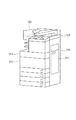
図2は、画像形成装置100の外観を示す外観図である。
FIG. 2 is an external view showing the external appearance of the
図2において、画像形成装置100に設けられた右カバー201、前カバー202、トナーカバー203が示されている。
In FIG. 2, a
右カバー201は、ジャム紙を除去するために、印刷用紙の搬送路を露出させるためのものである。前カバー202は、後述の転写ユニットを引き出し、ジャム紙を除去するためのものである。また、前カバー202は、ロック機構を備えており、ユーザが誤って前カバー202を開けないようにするために、自動的にロックして開かないようにすることができる。トナーカバー203は、トナーを交換する際に、トナー容器装着箇所を露出させるためのものである。上述した右カバー201、前カバー202、トナーカバー203の開閉状態を検知するセンサを画像形成装置100は備えている。
The
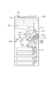
図3は、画像形成装置100の内部構造を示す断面図である。図3における内部構造は、例えばCMYK(シアン、マゼンタ、イエロー、ブラック)のフルカラーの画像形成装置での一例を示している。
FIG. 3 is a cross-sectional view showing the internal structure of the
感光ドラム301は、一次帯電気302により特定の極性電位に帯電処理され、図示しない露光手段によって303に示される位置がCPU101からの指示に従って露光される。このようにして例えばKに対応した静電潜像が形成される。
The
ロータリー現像機304は、トナーカートリッジと一体となった4つの現像機を具備する。静電潜像が形成されたあと、ロータリー現像機304の現像機の中のひとつにより、感光ドラム301にKに対応する画像が現像される。
The rotary developing
中間転写ベルト305は306が示す方向に駆動され、感光ドラムに現像されたKに対応する画像が、感光ドラムと中間転写ベルトの接合部分を通る過程で、一次転写ローラー307により形成された電界によって中間転写ベルトに転写される。中間転写ベルトに転写を終えた感光ドラム301の表面はクリーニング装置308によって清掃される。この処理を順次繰り返し、4色(マゼンタ、シアン、イエロー、ブラック)の画像を中間転写ベルトに重ね合わせて、カラー画像が形成される。単色の画像を形成する場合は一度だけ転写処理が行われる。
The
中間転写ベルト305に転写された画像は二次転写ローラー309部分でカセット310より給紙された用紙に印刷される。画像が印刷された用紙は定着機311で加熱され定着される。定着後、用紙はローラー312によって、排紙口313まで搬送され機外に排出される。両面印刷を行う場合は、反転パス314を通過して用紙を循環させ、印刷処理を繰り返す。また、二次転写ローラー309及び定着機311は、転写ユニットと呼ばれるひとつのユニットになっており、ジャム紙を取り除く際に、ユニットを引き出すことができる。
The image transferred to the
搬送部センサ315、両面部センサ316、転写部センサ317は、印刷用紙の滞留有無を検知する。また、読取部センサ321は、スキャナデバイス108における原稿用紙の滞留有無を検知する。これらのセンサによりジャムの発生が検知される。重送検知センサ319は、スキャナデバイス108で原稿を読み取る際に、原稿が複数枚重なって搬送されていないか(以下、重送とする)を検知する。重送検知センサ319としては、シート給送中の先行シートと重なった状態で後続シートが連れ送りされたことを検出できさえすれば、どのような方式のセンサを用いても構わない。例えばシート面の一方から超音波を照射し、対向側に到達する波形の減衰特性から重送状態を検出するセンサや、シート厚み方向の電気抵抗を測定することで重送状態を検出するセンサなどを用いることもできる。前カバーロックセンサ320は、前カバー202がロックされているか検知(ロック検知)する。これらのセンサは、メカ・フラグを用いたものでもよいし、光学的な素子を用いたものでもよい。
The
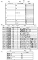
図4は、図1におけるストレージ111に記憶された動画リストテーブル400、及び動画テーブル410、センサ位置Bitテーブル420を示す図である。
FIG. 4 is a diagram showing the moving image list table 400, the moving image table 410, and the sensor position bit table 420 stored in the
図4(c)は、センサ位置Bitテーブル420を示す図である。センサ位置Bitテーブル420は、センサ421と、センサ位置Bit422とを対応付けるテーブルである。
FIG. 4C is a diagram showing the sensor position bit table 420. The sensor position bit table 420 is a table that associates the
センサ421は、画像形成装置100の内部のセンサの位置を示している。センサ位置Bit422は、各種センサ421が印刷用紙や原稿用紙の滞留等を検知した際に、それぞれに対応するBitをONにする場所を示す。
A
搬送部センサ315により搬送部でのジャムが検知された際は、Bit1がONになる。
When a jam in the transport unit is detected by the
両面部センサ316により両面部でのジャムが検知された際は、Bit2がONになる。
転写部センサ317により転写部でのジャムが検知された際は、Bit3がONになる。
When a jam at the transfer portion is detected by the
前カバーロックセンサ320により前カバー202がロックされたことが検知された際は、Bit4がONになる。
When the front
重送検知センサ319により重送が検知された際は、Bit5がONになる。
When double feed is detected by the double
読取部センサ321によりスキャナデバイス108におけるジャムが検知された際は、Bit6がONになる。
When the
図4(a)は、動画リストテーブル400を示す図である。動画リストテーブル400は、メンテナンス事象(ジャム、トナー不足等)と、当該メンテナンス事象の発生を検知した際に再生すべき動画との関連を定義するテーブルである。動画リストテーブル400には、メンテナンスID401と対応センサ位置Bit402、及び動画リスト403が対応付けて記憶されている。メンテナンスIDは、画像形成装置100において発生したメンテナンス事象を識別するためのメンテナンス識別情報である。
FIG. 4A is a diagram showing the moving image list table 400. The moving image list table 400 is a table that defines a relationship between a maintenance event (jam, toner shortage, etc.) and a moving image to be reproduced when the occurrence of the maintenance event is detected. The moving image list table 400 stores a
図4(a)において、メンテナンスID401の001は搬送部ジャムであり、センサ位置BitのBit1(搬送部センサ315)のみがONのとき検知される。002は転写部ジャムであり、センサ位置BitのBit3(転写部センサ317)のみがONのとき検知される。
In FIG. 4A, 001 of the
003は搬送部ジャム及び転写部ジャムであり、センサ位置BitのBit1(搬送部センサ315)、Bit3(転写部センサ317)、Bit4(前カバーロックセンサ320)がONのとき検知される。なお、ジャム紙が搬送部と転写部に跨る場合、前カバー202を開け、転写ユニットを引き出してしまうと、ジャム紙が切断され、紙が搬送部、転写部に残り、故障の原因になる可能性がある。そこで、搬送部と転写部に跨るようなジャムが発生した際は、前カバー202をロックすることで、誤って転写ユニットを引き出してジャム紙が切断されるのを防ぐよう制御される。よって、搬送部と転写部でのジャムを検出した場合、前カバーがロック状態となりセンサ位置BitのBit4がONとなる。
004はシアントナー不足であり、プリンタデバイス106により検知される。
004 is insufficient cyan toner and is detected by the
005は読取部ジャムであり、センサ位置BitのBit6のみがONのとき検知される。 005 is a reading unit jam, which is detected when only Bit 6 of the sensor position Bit is ON.
006は読取部重送検知ジャムであり、センサ位置BitのBit5とBit6がONのとき検知される。 006 is a reading portion double feed detection jam, which is detected when Bit 5 and Bit 6 at the sensor position Bit are ON.
動画リスト403は、各メンテナンス事象が発生した際に再生すべき動画のリストを示している。メンテナンス事象が発生した場合、該メンテナンス事象を解消するために必要な一連の操作手順をユーザに示す必要がある。該一連の操作手順は、例えばカバーを開ける手順、ジャム紙を除去する手順、カバーを閉じる手順など、複数の操作手順から構成されている。本実施形態では、メンテナンス事象毎に一連の操作手順を示す一本の動画を用意しておくのではなく、操作手順(操作要素)毎に動画を用意しておき、これらの動画を複数組み合わせて一連の操作手順をユーザに示すものとする。以下の説明では、該操作手順毎の動画を「部分動画」と呼ぶことにする。動画リスト403には、複数の部分動画の組み合わせと、各部分動画の再生順とがメンテナンスID401と対応づけて記憶されている。部分動画の組み合わせとは、例えばメンテナンスID401が001の場合は、それに対応する動画リスト403に示される部分動画A1、A2、A3、A6である。また、再生順は、記載されている順番であり、メンテナンスID401が001の場合はA1、A2、A3、A6の順に部分動画が再生されることになる。
The moving
図4(b)は、動画テーブル410を示す図である。動画テーブル410は、動画ID411と、動画ファイル412と、再生時間413と、カバー開閉フラグ414と、メッセージ415とを対応付けるテーブルである。
FIG. 4B is a diagram showing the moving image table 410. The moving image table 410 is a table that associates the moving
動画ID411は、部分動画を識別するためのIDであり、上述した動画リストテーブル400における動画リストでも用いられる。動画ファイル412は、再生する部分動画のファイル名とストレージ111における部分動画ファイルの位置とを示している。なお、ここでは部分動画ファイルがストレージ111内に記憶されているものとするが、ネットワークを介して接続されたサーバや、USBケーブルを介して接続された記憶デバイス等の外部装置に記憶しておき、必要な時に読み出す構成にしてもよい。
The moving
再生時間413は、その部分動画を再生してから終了するまでの再生時間を示している。
The
カバー開閉フラグ414は、画像形成装置100のカバーが開けられる前の手順を示す部分動画であるか、開けられた後の手順を示す部分動画であるかを示している。カバー開閉フラグが0の場合、カバーが開けられる前の手順を示す動画であることを示し、カバー開閉フラグが1の場合、カバーが開けられた後の手順を示す動画であることを示す。
The cover open /
メッセージ415は、対応する部分動画を再生中に表示するメッセージを示している。
A
各部分動画ファイルに示される操作手順は、以下の通りである。 The operation procedure shown in each partial moving image file is as follows.
部分動画A1には、右カバー201を開ける操作手順が示されている。
The partial moving image A1 shows an operation procedure for opening the
部分動画A2、A3には、搬送部センサ315付近のジャム紙を除去する操作手順、部分動画A4、A5には、転写部センサ317付近のジャム紙を除去する操作手順が示されている。
Partial moving images A2 and A3 show an operation procedure for removing jammed paper near the
部分動画A6には、右カバー201を閉める操作手順が示されている。
The partial moving image A6 shows an operation procedure for closing the
部分動画A7には、前カバー202を開ける操作手順が示されている。
The partial moving image A7 shows an operation procedure for opening the
部分動画A8には、前カバー202を閉める操作手順が示されている。
The partial moving image A8 shows an operation procedure for closing the
部分動画A9には、スキャナデバイス108のカバーを開ける操作手順が示されている。部分動画A10には、読取部センサ321付近のジャム紙を除去する操作手順が示されている。部分動画A11には、スキャナデバイス108のカバーを閉める操作手順が示されている。
The partial moving image A9 shows an operation procedure for opening the cover of the
部分動画B1には、トナーカバー203を開ける操作手順が示されている。部分動画B2には、空のマゼンタトナーカートリッジを取り出す操作手順、部分動画B3には、新しいマゼンタトナーカートリッジを準備する操作手順、部分動画B4には、新しいマゼンタトナーカートリッジを装着する操作手順が示されている。
An operation procedure for opening the
部分動画B5には、空のシアントナーカートリッジを取り出す操作手順、部分動画B6には、新しいシアントナーカートリッジを準備する操作手順、部分動画B7には、新しいシアントナーカートリッジを装着する操作手順が示されている。 The partial moving image B5 shows an operation procedure for taking out an empty cyan toner cartridge, the partial moving image B6 shows an operation procedure for preparing a new cyan toner cartridge, and the partial moving image B7 shows an operation procedure for installing a new cyan toner cartridge. ing.
部分動画B8には、空のイエロートナーカートリッジを取り出す操作手順、部分動画B9には、新しいイエロートナーカートリッジを準備する操作手順、部分動画B10には、新しいイエロートナーカートリッジを装着する操作手順が示されている。 Partial video B8 shows an operation procedure for removing an empty yellow toner cartridge, partial video B9 shows an operation procedure for preparing a new yellow toner cartridge, and partial video B10 shows an operation procedure for installing a new yellow toner cartridge. ing.
部分動画B11には、空のブラックトナーカートリッジを取り出す操作手順、部分動画B12には、新しいブラックトナーカートリッジを準備する操作手順、部分動画B13には、新しいブラックトナーカートリッジを装着する操作手順が示されている。 The partial moving image B11 shows an operation procedure for removing an empty black toner cartridge, the partial moving image B12 shows an operation procedure for preparing a new black toner cartridge, and the partial moving image B13 shows an operation procedure for installing a new black toner cartridge. ing.
部分動画B14には、トナーカバー203を閉める操作手順が示されている。
In the partial moving image B14, an operation procedure for closing the
図4(a)の動画リスト403の説明に戻る。例えば搬送部ジャムが発生した場合(メンテナンスIDが001)、最初に右カバー201を開ける操作手順を示す部分動画A1が再生される。そして、続いて搬送部センサ315付近のジャム紙を除去する操作手順を示す部分動画A2、A3、右カバー201を閉める操作手順を示す部分動画A6の順に再生される。ここで、メンテナンス事象である搬送部ジャムを解消するための操作手順を示しているのは部分動画A2、A3であり、部分動画A1はその準備のための操作手順を示していると言える。以下の説明では、メンテナンス事象を解消する手順の前に実施すべき操作手順を示す部分動画を「事前準備動画」と呼ぶことにする。また、メンテナンス事象を解消するための操作手順、言い換えると、事前準備動画で示される操作手順を実施した後に行う操作手順を示す部分動画を「本編動画」と呼ぶことにする。例えば、メンテナンスIDが001の場合、部分動画A1が事前準備動画、部分動画A2、A3、A6が本編動画となり、メンテナンスIDが004の場合、部分動画B1が事前準備動画、部分動画B5、B6、B7、B14が本編動画となる。本実施形態では、カバー開閉フラグ414が0の部分動画が事前準備動画となり、カバー開閉フラグ414が1の部分動画が本編動画となる。
Returning to the description of the moving
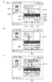
図5〜図7は、本実施例における表示デバイス115に表示される画面例を示す図である。以下、図5〜図7を用いて、本実施形態における表示画面の遷移の全体像について説明する。
5-7 is a figure which shows the example of a screen displayed on the
図5における画面500は、CPU101がストレージ111に記憶されているプログラムを実行することで表示データを生成し、表示制御部114を介して表示デバイス115に表示される。
A
図5(a)は、メンテナンス事象の発生を検知した際に表示される画面例である。ここでは、搬送部ジャムの発生を検知した場合(メンテナンスIDが001)を例として説明する。メンテナンスIDが001の場合、動画リストテーブル400によれば、動画IDがA1、A2、A3、A6の部分動画が順に再生されることとなる。図5(a)では、事前準備動画である部分動画A1の先頭で停止された状態の画面が表示されている。 FIG. 5A is an example of a screen displayed when the occurrence of a maintenance event is detected. Here, the case where the occurrence of the conveyance unit jam is detected (maintenance ID is 001) will be described as an example. When the maintenance ID is 001, according to the moving image list table 400, the partial moving images having the moving image IDs A1, A2, A3, and A6 are sequentially reproduced. In FIG. 5A, a screen in a state where it is stopped at the beginning of the partial moving image A1 that is a preparatory moving image is displayed.
画面500には、動画表示領域501、再生ボタン502、再生マーク503、再生時間表示ラベル504、バー505、スライダ506、チャプタ507、メッセージ領域508、アイコン509が表示されている。また、チャプタ507まで再生位置を移動させる、チャプタスキップ戻るボタン510、チャプタスキップ進むボタン511が表示されている。
On the
動画表示領域501は、メンテナンス手順を示す動画を表示するための領域である。再生ボタン502は、動画の再生を指示するためのボタンである。再生マーク503は、再生ボタン502と同じく、動画の再生を指示するためのマークである。再生ボタン502又は再生マーク503が押下(タッチ)されると、CPU101は動画の再生を開始する。
The moving
再生時間表示ラベル504は、再生する複数の部分動画の再生時間の総和(「総再生時間」と呼称する)と、これに対する現在の再生位置に対応する時間を示すものである。
The playback
バー505およびスライダ506は、動画全体における再生位置を示すとともに再生位置の移動を指示するためのシークバーを構成する。バー505は、総再生時間を模式的に示している。スライダ506は現在の再生位置を示すと共に再生位置の移動を指示するために使用される。スライダ506は、動画の再生状態に応じてバー505の範囲内で移動する。また、スライダ506をドラッグ(移動)することで、再生位置を任意の位置に移動させることができる。また、バー505の任意の位置が押下されると、その位置まで動画の再生を進めることができ、スライダ506もその再生位置に付随して移動する。チャプタ507は、動画の区切りの位置を示し、その位置まで動画が再生されると、自動で停止される。
The
再生時間表示ラベル504、チャプタ507について具体的に説明する。メンテナンスIDが001の場合、動画リストテーブル400によれば、部分動画A1、A2、A3、A6が順に再生されることとなる。これらの部分動画の再生時間は、動画テーブル410によればそれぞれ10秒(00:10)、20秒(00:20)、20秒(00:20)、10秒(00:10)である。総再生時間は、再生する部分動画の再生時間の総和であるため、この場合は1分00秒(01:00)となる。一方、再生時間は、総再生時間に対する現在の再生位置を示す。例えば、1番目に再生する部分動画A1の先頭から5秒(00:05)経過したシーンを表示しているとする。この場合には、そのまま5秒が再生時間となる。また、2番目に再生する部分動画A2の先頭から10秒が経過したシーンを表示しているとする。この場合には、部分動画A1の再生を終えているので、A1の再生時間10秒と、A2の再生済みの時間10秒を加算して20秒(00:20)が再生時間となる。再生時間表示ラベル504は、このようにして計算した再生時間と総再生時間とが、スラッシュ(/)で連結した文字列として表示される。
The reproduction
チャプタ507は一連の操作手順のうち、区切りとなる位置に表示され、動画がその位置まで再生されると、動画の再生が自動で一時停止される。チャプタ507は、部分動画の再生が切り替わる位置(A1とA2、A2とA3、A3とA6)の3箇所に表示される。また、動画全体の先頭と末尾の2箇所にもチャプタ507を表示してもよい。
The
図5(a)では、上記の5箇所にチャプタ507を表示した場合の例を示している。
FIG. 5A shows an example in which
チャプタスキップ戻るボタン510、チャプタスキップ進むボタン511は、動画の再生位置をチャプタ507まで移動させるボタンである。例えば、再生時間00:00の状態で、チャプタスキップ進むボタン511が押下されると、再生時間00:10のチャプタ507に再生位置とスライダ506が移動される。また、再生時間01:00の状態で、チャプタスキップ戻るボタン510が押下されると、再生時間00:50のチャプタ507に再生位置とスライダ506が移動される。
The chapter
メッセージ領域508には、再生中の部分動画の内容を補足するメッセージが表示される。具体的には、部分動画A1が再生されているときは、動画テーブル410内のメッセージ415に基づいて、“右カバーを開けてください。”が表示される。尚、メッセージ領域508は、対応する部分動画の再生を開始してから一定時間後に非表示にしても良いし、対応する部分動画が表示されている間は表示し続けても良い。
In the
アイコン509は、画像形成装置100においてメンテナンス事象が発生している箇所を示す。具体的には、メンテナンスIDが001の場合、搬送部ジャムが発生しているため、アイコン509では搬送部が示されている。
An
メッセージ516は、前カバーがロックされており、前カバーロックセンサ320が検知している際に、ユーザにその旨を知らせるメッセージが表示される。
As the
図5(a)の画面において、再生ボタン502又は再生マーク503が押下されると、動画の再生が開始される。メンテナンスIDが001の場合、CPU101は事前準備動画である部分動画A1の再生を開始する。図5(b)は、部分動画A1の再生が開始されてから2秒後の画面例を示している。動画の再生開始に応じて、再生ボタン502及び再生マーク503が非表示となり、再生ボタン502に代わって同位置に一時停止ボタン512が表示される。
When the
図5(c)は、再生位置が部分動画A2の末尾まで到達した時の画面例を示した図である。部分動画A2の再生が終了した時点、すなわちチャプタ516の位置で動画の再生が自動的に一時停止される。そして、再生マーク513と共にリプレイマーク514が表示される。また、一時停止ボタン512は非表示となり、同表示位置に再生ボタン515が表示される。リプレイマーク514は、現在停止されている部分動画の先頭からの再生を指示するためのマークである。具体的には、チャプタ516の位置で停止中に、リプレイマーク514が押下されると、CPU101は部分動画A2の先頭に移動して動画の再生を再開する。このように、作業単位でチャプタを配置し、そこまでの再生が終了した時点で動画の再生を自動的に一時停止することにより、ユーザの意図とは関係なく、先の操作手順を示す動画に進んでしまうのを防ぐことができる。また、一時停止した際には、再生マーク513と共にリプレイマーク514を表示するので、次の操作手順の動画に進むのか、もう一度動画を見直すのかを容易に選択することができる。
FIG. 5C shows an example of a screen when the playback position reaches the end of the partial moving image A2. When the reproduction of the partial moving image A2 is completed, that is, at the position of the
図5(c)の画面において、再生マーク513又は再生ボタン515が押下されると、部分動画A3の再生が開始される。
When the
図6(a)は、部分動画A3の再生が開始されてから3秒後の画面例を示した図である。 FIG. 6A is a diagram showing a screen example 3 seconds after the reproduction of the partial moving image A3 is started.
図6(b)は、部分動画A3の再生途中で一時停止ボタン又は動画表示領域が押下された時の画面例を示した図である。一時停止ボタン又は動画表示領域が押下されると、動画の再生が停止され、再生マーク601と共にリプレイマーク602が表示される。
FIG. 6B is a diagram illustrating a screen example when the pause button or the moving image display area is pressed during the reproduction of the partial moving image A3. When the pause button or the moving image display area is pressed, the reproduction of the moving image is stopped and the
図6(c)は、図6(b)の画面におけるリプレイマーク602、又はチャプタスキップ戻るボタン603が押下された時に表示される画面例を示した図である。リプレイマーク602又はチャプタスキップ戻るボタン603が押下されると、部分動画A3の先頭(チャプタ606)に移動して動画の再生が再開される。
FIG. 6C is a diagram showing an example of a screen displayed when the
このように、ユーザによる意図的な操作によって動画が一時停止した場合も、部分動画の再生終了により自動的に一時停止された場合と同様に、再生マークと共にリプレイマークが表示される。 As described above, even when the moving image is paused by an intentional operation by the user, the replay mark is displayed together with the reproduction mark, similarly to the case where the moving image is automatically stopped when the reproduction of the partial moving image is ended.
図7は特定のメンテナンス事象が発生した場合に、詳細なメンテナンス手順を示す動画(図5、6)を表示する前に表示される専用画面の例を示した図である。 FIG. 7 is a diagram showing an example of a dedicated screen displayed before displaying a moving image (FIGS. 5 and 6) showing a detailed maintenance procedure when a specific maintenance event occurs.
図7(a)は、メンテナンスIDが003、すなわち搬送部ジャム及び転写部ジャムが発生し前カバーがロックされた際に最初に表示される画面例を示した図である。上述した通り、搬送部と転写部に跨るようなジャムが発生した際は、誤って転写ユニットを引き出してジャム紙が切断されるのを防ぐために、前カバー202をロックするよう制御される。しかし、ユーザが、前カバー202のロックに気づかずに無理やり開けようとしてしまうと、前カバー202の故障の原因になってしまう。そこで、ジャムが発生した際に、図5、図6のような詳細の手順を表示する前に図7(a)で示す画面を表示することにより、前カバー202がロックされていることをユーザに注意喚起することができる。
FIG. 7A is a diagram showing an example of a screen that is displayed first when the maintenance ID is 003, that is, when the transport unit jam and the transfer unit jam occur and the front cover is locked. As described above, when a jam occurs between the transport unit and the transfer unit, the
詳細手順へボタン701は、図5、図6のようなジャム紙を取り除くための手順を示す動画へ表示を切替えるためボタンである。
A
図7(b)は、メンテナンスIDが006、すなわち原稿搬送デバイス109で原稿を読み取る際に原稿の重送が起き、ジャムが発生した場合に最初に表示される画面例を示した図である。重送が起きた際は、複数枚の原稿同士がくっついた状態になっている場合があり、ジャムの解除後にそのままの状態で原稿の読み取りを再開すると、再び重送が起きてしまう可能性がある。そこで、図7(b)の画面例のように、その解消方法(原稿の読み取り再開前に原稿をさばく)をユーザに示すことで、重送の再発を防止することができる。
FIG. 7B is a diagram illustrating an example of a screen that is displayed first when the maintenance ID is 006, that is, when a document is double-fed and a jam occurs when the
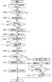
図8は、CPU101により実行されるメンテナンス手順の表示処理を示すフローチャートである。
FIG. 8 is a flowchart showing a maintenance procedure display process executed by the
図8における処理は、上述した各種センサが示す値の変化をプリンタ制御部105及び画像読取制御部107が検知することにより開始される。
The processing in FIG. 8 is started when the
まず、CPU101は、いずれのメンテナンス事象が発生したかを判定し、メンテナンスIDを特定する(S801)。例えば、搬送部センサ315付近でジャムが発生した場合、センサ位置Bit1のみがONとなることから、CPU101は、図4(a)の動画リストテーブル400より、メンテナンスIDを001(搬送部ジャム)と特定する。また、搬送部と転写部に跨る位置でジャムが発生した場合、センサ位置Bit1、3、4がONとなることから、CPU101はメンテナンスIDを003(搬送部転写部ジャム)と特定する。
First, the
続いて、CPU101は、特定のセンサ位置BitがONか否かを判断する(S802)。ここで言う特定のセンサ位置Bitとは、Bit4(前カバーロックセンサ320)とBit5(重送検知センサ319)のことを指しており、これらのセンサ位置BitがどちらかONであれば、CPU101は、S803の処理に進む。これらのセンサ位置BitがどちらかONでなければ、CPU101は、S806の処理に進む。
Subsequently, the
特定のセンサ位置BitがONである場合(S802でYes)、CPU101は、図7で示すようなユーザの注意喚起を行うための専用画面を表示デバイス115に出力する(S803)。Bit4がONの場合は図7(a)に示す画面、Bit5がONの場合は図7(b)に示す画面が、それぞれ表示デバイス115に出力される。
When the specific sensor position Bit is ON (Yes in S802), the
続いて、CPU101は、詳細手順へボタン701の押下を検知したか否か判断する(S804)。詳細手順へボタン701の押下を検知した場合、CPU101は、自動再生フラグをONにしてRAM104に記憶する(S805)。
Subsequently, the
S806では、CPU101は、動画リストテーブル400を参照し、S801で特定したメンテナンスIDに対応する部分動画のリストを読み込む。そして、CPU101は、読み込んだ部分動画のリストに従って、部分動画の取得を行う(S807)。例えば、特定したメンテナンスIDが001の場合、再生する部分動画はA1、A2、A3、A6である。また、特定したメンテナンスIDが003の場合、再生する部分動画はA1、A2、A3、A6、A7、A4、A5、A8である。CPU101は、特定した複数の部分動画をその再生順で、例えば配列情報としてRAM104に一時的に記憶しておく。
In step S806, the
S808では、CPU101は、S806で読み込んだリストの部分動画を全て取得したか判断し、全て取得した場合はS809に、全て取得していない場合はS807の処理に進む。
In step S808, the
続いて、CPU101は、動画の総再生時間を算出する(S809)。CPU101は、動画テーブル410に基づいて、S807で取得した部分動画各々の再生時間413を取得し、これらの総計を算出する。CPU101は、算出した総再生時間に基づいて再生時間表示ラベル(図5(a)の504等)を表示する。
Subsequently, the
S810では、CPU101は、RAM104に記憶されている自動再生フラグがONか否か判断し、ONである場合はS811に、ONでない場合はS813の処理に進む。
In S810, the
自動再生フラグがOFFの場合、CPU101は、先頭の動画IDの部分動画をRAM104に読み込み、停止状態で表示デバイス115に出力する(S813)。例えば、メンテナンスIDが001の場合、CPU101は、先頭の部分動画A1をRAM104に読み込み、停止状態で表示デバイス115に出力する。併せて、CPU101は再生マーク及び再生ボタンを表示デバイス115に出力する(S814)。図5(a)はこのときの画面例である。そして、CPU101はユーザによる再生ボタン502又は再生マーク503の押下を検知すると(S815)、先頭の部分動画の再生を開始する(S816)。ジャムの発生等のメンテナンス事象は、画像形成装置100によるスキャン動作、プリント動作等を実行中はいつでも発生する可能性があり、当該メンテナンス事象が発生した時点で、ユーザが表示デバイス115を見ているとは限らない。よって、メンテナンス事象の発生に従ってメンテナンス手順を示す動画の画面に遷移した場合には、自動的に動画の再生を開始せずにユーザによる再生開始の操作を待ってから動画の再生を開始する。これにより、ユーザによる手順の見逃しを防ぐことができる。
When the automatic reproduction flag is OFF, the
一方、自動再生フラグがONの場合、CPU101は、先頭の動画IDの部分動画をRAM104に読み込み、再生状態で表示デバイス115に出力する(S811)。例えば、メンテナンスIDが003の場合、CPU101は、先頭の部分動画A1をRAM104に読み込み、再生を開始する。CPU101は、動画の再生開始後に自動再生フラグをOFFにする(S812)。上述の通り、メンテナンス事象が発生した時点ではユーザが表示デバイス115を見ているとは限らないが、図7のような画面を表示中に詳細手順へボタン701が押下されたということは、ユーザが表示デバイス115を見ながら操作しているということである。このような場合にまでユーザによる動画再生開始の操作を行わせるようにすると、操作ステップ数が増えてしまい、かえって操作性を低下させてしまう恐れがある。よって、特定のメンテナンス事象の発生に従って図7に示す画面を表示した後、ユーザによる操作に応じてメンテナンス手順を示す動画の画面に遷移した場合には、自動的に動画の再生を開始する。これにより、ユーザが詳細手順へボタン701を押下した後に、再生ボタン502又は再生マーク503を押下して動画を再生させる、といった操作の手間を省くことができる。
On the other hand, when the automatic reproduction flag is ON, the
なお、S809において、CPU101は、動画テーブル410の再生時間413を利用して総再生時間の算出を行っているが、再生時間413を使用しなくても良い。つまり、CPU101は、対応する複数の部分動画をRAM104に読み込み、それぞれの部分動画のフレームレートと総フレーム数から各部分動画の再生時間を計算し、その値から総再生時間を算出するようにしても良い。
In S809, the
また、動画の形式やコーデックについては、本発明により特に制限するものではなく、様々な形態を取ることができる。 The moving image format and codec are not particularly limited by the present invention, and can take various forms.
以上のように、本実施形態における画像形成装置は、複数のメンテナンス事象のうち、特定のメンテナンス事象の発生が検出された場合には、詳細なメンテナンス手順を示す動画の表示前に、ユーザへ注意喚起させるための特定の画面を表示する。これにより、画像形成装置100の故障の要因となる行為や再度のメンテナンス事象の発生を防ぐことができる。
As described above, when the occurrence of a specific maintenance event is detected among a plurality of maintenance events, the image forming apparatus according to the present embodiment pays attention to the user before displaying a moving image indicating a detailed maintenance procedure. Display a specific screen to arouse. As a result, it is possible to prevent an action that causes a failure of the
また、上記特定のメンテナンス事象以外のメンテナンス事象が発生した場合は、動画を停止した状態で表示し、ユーザによる再生開始の操作を受けてから動画の再生が開始される。これにより、メンテナンス事象の発生に応じてメンテナンス手順を示す動画の再生が自動的に開始されることによる、ユーザによる手順の見逃しを防ぐことができる。また、上記特定のメンテナンス事象を検出したことに従って上記特定の画面を表示後、ユーザによる操作に応じてメンテナンス手順を示す動画の画面に遷移した場合には、自動的に動画の再生を開始する。これにより、動画の画面遷移時に一律停止状態で表示することによるユーザによる操作性の低下を防ぐことができる。 Further, when a maintenance event other than the specific maintenance event occurs, the moving image is displayed in a stopped state, and the reproduction of the moving image is started after receiving a reproduction start operation by the user. Thereby, it is possible to prevent the user from overlooking the procedure due to the automatic reproduction of the moving image showing the maintenance procedure in response to the occurrence of the maintenance event. In addition, after the specific screen is displayed according to the detection of the specific maintenance event, when a transition is made to a moving image screen indicating a maintenance procedure according to an operation by the user, the reproduction of the moving image is automatically started. Thereby, the fall of the operativity by a user by displaying by a uniform stop state at the time of the screen transition of a moving image can be prevented.
(第2の実施形態)
次に本発明を実施するための第2の実施形態について、第1の実施形態との差分を中心に説明する。本実施形態では、専用画面を表示している状態で、メンテナンス事象に関連するカバーがオープンされた場合、カバーオープン後の動画に再生位置を移動した上で、自動で動画の再生を開始する例について説明する。
(Second Embodiment)
Next, a second embodiment for carrying out the present invention will be described focusing on differences from the first embodiment. In this embodiment, when a cover related to a maintenance event is opened while the dedicated screen is displayed, the playback position is moved to the video after opening the cover, and the playback of the video is automatically started. Will be described.
図9は、CPU101により実行されるメンテナンス手順の表示処理を示すフローチャートである。
FIG. 9 is a flowchart showing a maintenance procedure display process executed by the
S901〜S916は、図8のS801〜S816と同様のため、説明を割愛する。
S903において専用画面が表示された後、CPU101は、現在発生しているメンテナンス状態に対応するカバーが開けられたか判断する(S917)。例えば、メンテナンスIDが003の状態(搬送部ジャム及び転写部ジャム)が発生した場合、動画リストテーブル400より、最初に表示される動画は、右カバー201を開ける操作手順を示す部分動画A1である。よって、CPU101は、右カバー201のセンサを検知し、右カバー201が開けられたか判断する。対応するカバーが開けられたと判断した場合、CPU101は、カバーオープンフラグをONにしてRAM104に記憶する(S918)。対応するカバーが開けられていないと判断した場合、CPU101は、詳細手順へボタン701が押下されたか否かを判断する(S904)。こうして、専用画面を表示中に対応するカバーが開けられるか、詳手順へボタン701が押下されると、S905以降の処理に進む。
Since S901 to S916 are the same as S801 to S816 in FIG.
After the dedicated screen is displayed in S903, the
S910において自動再生フラグがONであると判断された場合、CPU101は、RAM104に記憶されているカバーオープンフラグがONか否か判断し(S919)、ONである場合はS920に、ONでない場合はS911の処理に進む。
If it is determined in S910 that the automatic regeneration flag is ON, the
S920では、CPU101は、カバー開閉フラグ414より、動画の再生位置を、カバーが開けられた後の動画ID群の先頭に移動する。例えば、メンテナンスIDが003の場合、カバーが開けられた後の動画ID群の先頭は、動画リストテーブル400より、部分動画A2であるため、CPU101は、部分動画A2の先頭に動画の再生位置を移動する。そして、S911において部分動画A2から動画の再生が開始される。S921では、CPU101は、カバーオープンフラグをOFFにしてRAM104に記憶する。
In step S920, the
このように本実施形態の画像形成装置100は、特定のメンテナンス事象の検出に従って特定の画面を表示した後、当該メンテナンス事象に関連するカバーが開けられたことを検知した場合には、詳細手順を示す動画の画面に自動的に画面遷移する。上述した通り、メンテナンス事象が発生した時点ではユーザが表示デバイス115を見ているとは限らない。一方、メンテナンス事象に関連するカバーが開けられたということは、ユーザは表示デバイス115を見てメンテナンス事象の発生を認識し、該メンテナンス事象を解消するための操作を開始したものと想定される。よって、このような場合には自動的に動画の画面に遷移させることで、ユーザによる操作の手間を省くことができる。更に、当該カバーが開けられたことを検知した場合には、当該カバーを開ける手順を示す部分動画の再生を省略し、次の手順の部分動画から動作の再生を開始することで、ユーザによる操作性を向上させることが出来る。
As described above, the
(その他の実施形態)
なお、上記実施形態ではコピー機能、スキャナ機能等の複数の機能を有する画像形成装置100を例として説明したが、このうち一部の機能のみを有する画像処理装置にも本発明は適用可能である。
(Other embodiments)
In the above embodiment, the
また、本発明は、以下の処理を実行することによっても実現される。即ち、上述した実施形態の機能を実現するソフトウェア(プログラム)を、ネットワーク又は各種記憶媒体を介してシステム或いは装置に供給し、そのシステム或いは装置のコンピュータ(またはCPUやMPU等)がプログラムを読み出して実行する処理である。この場合、そのコンピュータプログラム、及び該コンピュータプログラムを記憶した記憶媒体は本発明を構成することになる。 The present invention can also be realized by executing the following processing. That is, software (program) that realizes the functions of the above-described embodiments is supplied to a system or apparatus via a network or various storage media, and a computer (or CPU, MPU, or the like) of the system or apparatus reads the program. It is a process to be executed. In this case, the computer program and the storage medium storing the computer program constitute the present invention.
100 画像形成装置
101 CPU
111 ストレージ
100
111 storage
Claims (9)
用紙の搬送路であって、所定のカバーが開いているときにユーザにより引き出すことが可能な第1の搬送路と、
前記第1の搬送路上を搬送された用紙が続いて搬送される第2の搬送路と、
前記第1の搬送路上での用紙のジャムを検出する第1の検出手段と、
前記第2の搬送路上での用紙のジャムを検出する第2の検出手段と、
前記第1の検出手段と前記第2の検出手段との両方で用紙のジャムを検出した場合に、前記所定のカバーが開かないようにロックするロック手段と、
前記第1の検出手段または前記第2の検出手段により検出されたジャムを解消するために必要な作業を示す動画を表示する表示制御手段と、を有し、
前記表示制御手段は、前記第1の検出手段と前記第2の検出手段の両方で用紙のジャムを検出した場合、前記所定のカバーがロックされていることを示す特定の画面を表示し、前記特定の画面の表示中に前記動画への切り替えを指示するユーザからの操作を受け付けるのに従って、前記特定の画面から前記動画へ表示を切り替え、前記第1の検出手段と前記第2の検出手段のうち、いずれか一方のみでジャムを検出した場合、前記特定の画面を表示することなく、前記動画を表示することを特徴とする画像形成装置。 An image forming apparatus,
A first conveyance path that is a paper conveyance path that can be pulled out by a user when a predetermined cover is open ;
A second conveyance path through which the sheet conveyed on the first conveyance path is subsequently conveyed;
First detection means for detecting a jam of the paper on the first conveyance path;
Second detection means for detecting a jam of the paper on the second conveyance path;
And locking means to lock the when detecting the jamming of both the paper and the said first detector means and the second detecting means, the predetermined cover does not open,
Have a, display control means for displaying a video showing the work required to overcome the detected jam by said first detection means or said second detection means,
The display control means displays a specific screen indicating that the predetermined cover is locked when both the first detection means and the second detection means detect a paper jam, As the operation from the user instructing the switching to the moving image is accepted during the display of the specific screen, the display is switched from the specific screen to the moving image, and the first detection unit and the second detection unit When the jam is detected by only one of them, the moving image is displayed without displaying the specific screen .
ジャムの種類を識別するためのジャム識別情報に対応づけて、再生すべき部分動画の組み合わせを示す情報を記憶する第2の記憶手段と、
検出されたジャムを識別するためのジャム識別情報に対応づけて前記第2の記憶手段に記憶されている、部分動画の組み合わせを示す情報に基づいて、前記第1の記憶手段に記憶されている複数の部分動画の中から、再生すべき複数の部分動画を取得する取得手段と、を有し、
前記表示制御手段は、前記取得手段により取得した複数の部分動画を組み合わせて一つの動画として表示することを特徴とする請求項5又は6に記載の画像形成装置。 First storage means for storing a plurality of partial videos provided for each operation to be performed on the image forming apparatus;
Second storage means for storing information indicating a combination of partial videos to be reproduced in association with jam identification information for identifying the type of jam;
Based on the information indicating the combination of the partial moving images stored in the second storage unit in association with the jam identification information for identifying the detected jam, stored in the first storage unit. Obtaining means for acquiring a plurality of partial videos to be reproduced from a plurality of partial videos;
Wherein the display control unit, an image forming apparatus according to claim 5 or 6, characterized in that to display as a single video by combining a plurality of partial videos acquired by the acquisition unit.
前記第1のセンサと前記第2のセンサ両方で用紙のジャムを検出した場合に、前記所定のカバーが開かないようにロックするロック工程と、
前記第1のセンサまたは、前記第2のセンサで検出されたジャムを解消するために必要な作業を示す動画を表示する表示制御工程と、
を有し、
前記表示制御工程は、前記第1のセンサと前記第2のセンサの両方で用紙のジャムを検出した場合、前記所定のカバーがロックされていることを示す特定の画面を表示し、前記特定の画面の表示中に前記動画への切り替えを指示するユーザからの操作を受け付けるのに従って、前記特定の画面から前記動画へ表示を切り替え、前記第1のセンサと前記第2のセンサのうち、いずれか一方のみでジャムを検出した場合、前記特定の画面を表示することなく、前記動画を表示することを特徴とする画像形成装置の制御方法。A sheet conveyance path , which is a first conveyance path that can be pulled out by a user when a predetermined cover is open, and a sheet that is conveyed on the first conveyance path is subsequently conveyed. An image forming apparatus including: a first conveyance path; a first sensor that detects a paper jam on the first conveyance path; and a second sensor that detects a paper jam on the second conveyance path. Control method,
A locking step of locking the predetermined cover so that it does not open when a paper jam is detected by both the first sensor and the second sensor;
A display control step for displaying a moving image indicating a work necessary for eliminating the jam detected by the first sensor or the second sensor ;
I have a,
In the display control step, when a paper jam is detected by both the first sensor and the second sensor, a specific screen indicating that the predetermined cover is locked is displayed. In response to receiving an operation from a user instructing switching to the moving image while the screen is being displayed, the display is switched from the specific screen to the moving image, and one of the first sensor and the second sensor. A control method for an image forming apparatus , wherein when only one of the jams is detected, the moving image is displayed without displaying the specific screen .
Priority Applications (6)
| Application Number | Priority Date | Filing Date | Title |
|---|---|---|---|
| JP2016007425A JP6184535B2 (en) | 2016-01-18 | 2016-01-18 | Image processing apparatus, control method thereof, and computer program. |
| EP17151128.0A EP3193214B1 (en) | 2016-01-18 | 2017-01-12 | Image processing apparatus, method for controlling the same, and program |
| US15/406,470 US10136024B2 (en) | 2016-01-18 | 2017-01-13 | Image processing apparatus, method for controlling the same, and storage medium |
| CN202011089228.4A CN112230526B (en) | 2016-01-18 | 2017-01-16 | Image processing apparatus and control method thereof |
| CN201710029753.9A CN106980244A (en) | 2016-01-18 | 2017-01-16 | Image processing apparatus and its control method |
| KR1020170007893A KR102119584B1 (en) | 2016-01-18 | 2017-01-17 | Image forming apparatus, method for controlling the same, and storage medium |
Applications Claiming Priority (1)
| Application Number | Priority Date | Filing Date | Title |
|---|---|---|---|
| JP2016007425A JP6184535B2 (en) | 2016-01-18 | 2016-01-18 | Image processing apparatus, control method thereof, and computer program. |
Related Child Applications (1)
| Application Number | Title | Priority Date | Filing Date |
|---|---|---|---|
| JP2017144394A Division JP6440786B2 (en) | 2017-07-26 | 2017-07-26 | Image processing apparatus, control method therefor, and computer program |
Publications (2)
| Publication Number | Publication Date |
|---|---|
| JP2017129640A JP2017129640A (en) | 2017-07-27 |
| JP6184535B2 true JP6184535B2 (en) | 2017-08-23 |
Family
ID=57794171
Family Applications (1)
| Application Number | Title | Priority Date | Filing Date |
|---|---|---|---|
| JP2016007425A Active JP6184535B2 (en) | 2016-01-18 | 2016-01-18 | Image processing apparatus, control method thereof, and computer program. |
Country Status (5)
| Country | Link |
|---|---|
| US (1) | US10136024B2 (en) |
| EP (1) | EP3193214B1 (en) |
| JP (1) | JP6184535B2 (en) |
| KR (1) | KR102119584B1 (en) |
| CN (2) | CN112230526B (en) |
Families Citing this family (5)
| Publication number | Priority date | Publication date | Assignee | Title |
|---|---|---|---|---|
| JP6808499B2 (en) * | 2017-01-11 | 2021-01-06 | キヤノン株式会社 | Image processing device, control method of image processing device, and program |
| JP7129198B2 (en) * | 2018-04-09 | 2022-09-01 | キヤノン株式会社 | IMAGE FORMING APPARATUS, NOTIFICATION METHOD AND PROGRAM |
| JPWO2020071545A1 (en) * | 2018-10-04 | 2021-06-03 | パロニム株式会社 | Information processing device |
| JP2021149023A (en) * | 2020-03-23 | 2021-09-27 | 東芝テック株式会社 | Image forming apparatus and program |
| JP7435177B2 (en) * | 2020-03-31 | 2024-02-21 | ブラザー工業株式会社 | reading device |
Family Cites Families (21)
| Publication number | Priority date | Publication date | Assignee | Title |
|---|---|---|---|---|
| JP2000147850A (en) * | 1998-11-06 | 2000-05-26 | Fuji Xerox Co Ltd | Sheet carrying device |
| JP2005346013A (en) * | 2004-06-07 | 2005-12-15 | Canon Inc | Image forming system, maintenance method and program |
| JP2008170865A (en) * | 2007-01-15 | 2008-07-24 | Kyocera Mita Corp | Image forming apparatus |
| JP2008281601A (en) * | 2007-05-08 | 2008-11-20 | Konica Minolta Business Technologies Inc | Image forming apparatus |
| JP4362578B2 (en) | 2007-05-10 | 2009-11-11 | シャープ株式会社 | Operating procedure display system |
| JP2009145689A (en) * | 2007-12-14 | 2009-07-02 | Sharp Corp | Information display device and image forming apparatus provided with the same |
| JP2010039391A (en) * | 2008-08-07 | 2010-02-18 | Kyocera Mita Corp | Image forming device |
| JP2012203412A (en) * | 2011-03-25 | 2012-10-22 | Toshiba Corp | Image forming apparatus and paper jam removal method of image forming apparatus |
| JP5822131B2 (en) * | 2011-11-30 | 2015-11-24 | 株式会社リコー | Processing procedure notification device and image forming apparatus |
| JP6097535B2 (en) * | 2012-11-29 | 2017-03-15 | キヤノン株式会社 | Image forming apparatus, control method therefor, and program |
| JP2014104728A (en) * | 2012-11-29 | 2014-06-09 | Canon Inc | Image forming apparatus, and control method and program of the same |
| JP6097541B2 (en) * | 2012-12-07 | 2017-03-15 | キヤノン株式会社 | Image forming apparatus, control method thereof, and program |
| JP2014119511A (en) * | 2012-12-13 | 2014-06-30 | Ricoh Co Ltd | Image forming apparatus |
| JP2014134753A (en) | 2012-12-13 | 2014-07-24 | Ricoh Co Ltd | Image forming apparatus |
| JP6129785B2 (en) * | 2013-09-30 | 2017-05-17 | 京セラドキュメントソリューションズ株式会社 | Image forming apparatus and printer driver |
| JP6366248B2 (en) * | 2013-10-11 | 2018-08-01 | キヤノン株式会社 | Image forming apparatus, control method therefor, and program |
| JP5906227B2 (en) * | 2013-10-21 | 2016-04-20 | キヤノン株式会社 | Image forming apparatus, control method therefor, and computer program |
| JP6223153B2 (en) * | 2013-11-29 | 2017-11-01 | キヤノン株式会社 | Image forming apparatus, control method therefor, and computer program |
| JP6355326B2 (en) * | 2013-12-17 | 2018-07-11 | キヤノン株式会社 | Image forming system, image forming system control method, and computer program |
| JP2015118460A (en) | 2013-12-17 | 2015-06-25 | キヤノン株式会社 | Image formation device, maintenance procedure presenting method, computer program |
| JP6338399B2 (en) * | 2014-02-27 | 2018-06-06 | キヤノン株式会社 | Image reading device |
-
2016
- 2016-01-18 JP JP2016007425A patent/JP6184535B2/en active Active
-
2017
- 2017-01-12 EP EP17151128.0A patent/EP3193214B1/en active Active
- 2017-01-13 US US15/406,470 patent/US10136024B2/en active Active
- 2017-01-16 CN CN202011089228.4A patent/CN112230526B/en active Active
- 2017-01-16 CN CN201710029753.9A patent/CN106980244A/en active Pending
- 2017-01-17 KR KR1020170007893A patent/KR102119584B1/en active IP Right Grant
Also Published As
| Publication number | Publication date |
|---|---|
| KR20170086412A (en) | 2017-07-26 |
| US20170208205A1 (en) | 2017-07-20 |
| EP3193214B1 (en) | 2021-03-17 |
| US10136024B2 (en) | 2018-11-20 |
| JP2017129640A (en) | 2017-07-27 |
| KR102119584B1 (en) | 2020-06-08 |
| EP3193214A1 (en) | 2017-07-19 |
| CN112230526A (en) | 2021-01-15 |
| CN106980244A (en) | 2017-07-25 |
| CN112230526B (en) | 2023-08-25 |
Similar Documents
| Publication | Publication Date | Title |
|---|---|---|
| US11240391B2 (en) | Image forming apparatus for displaying information for performing maintenance on the image forming apparatus, and method and program for controlling the same | |
| JP6184535B2 (en) | Image processing apparatus, control method thereof, and computer program. | |
| JP6223153B2 (en) | Image forming apparatus, control method therefor, and computer program | |
| CN107870750B (en) | Image processing apparatus, control method of image processing apparatus, and storage medium | |
| JP7091520B2 (en) | Image processing device, control method of image processing device, and program | |
| JP2017209870A (en) | Image processing device, control method and computer program thereof | |
| JP6808499B2 (en) | Image processing device, control method of image processing device, and program | |
| JP6440786B2 (en) | Image processing apparatus, control method therefor, and computer program | |
| JP6270892B2 (en) | Image processing apparatus, control method therefor, and computer program | |
| US10078799B2 (en) | Image forming apparatus, information processing apparatus, method of controlling the image forming apparatus and computer readable medium | |
| JP6456469B2 (en) | Image processing apparatus, control method therefor, and computer program | |
| JP7114756B2 (en) | IMAGE PROCESSING APPARATUS, CONTROL METHOD THEREOF, AND COMPUTER PROGRAM | |
| JP6759318B2 (en) | Image processing device, its control method, and computer program |
Legal Events
| Date | Code | Title | Description |
|---|---|---|---|
| A521 | Request for written amendment filed |
Free format text: JAPANESE INTERMEDIATE CODE: A523 Effective date: 20170607 |
|
| TRDD | Decision of grant or rejection written | ||
| A01 | Written decision to grant a patent or to grant a registration (utility model) |
Free format text: JAPANESE INTERMEDIATE CODE: A01 Effective date: 20170627 |
|
| A61 | First payment of annual fees (during grant procedure) |
Free format text: JAPANESE INTERMEDIATE CODE: A61 Effective date: 20170725 |
|
| R151 | Written notification of patent or utility model registration |
Ref document number: 6184535 Country of ref document: JP Free format text: JAPANESE INTERMEDIATE CODE: R151 |