JP6180810B2 - Inverter-integrated electric compressor - Google Patents
Inverter-integrated electric compressor Download PDFInfo
- Publication number
- JP6180810B2 JP6180810B2 JP2013128546A JP2013128546A JP6180810B2 JP 6180810 B2 JP6180810 B2 JP 6180810B2 JP 2013128546 A JP2013128546 A JP 2013128546A JP 2013128546 A JP2013128546 A JP 2013128546A JP 6180810 B2 JP6180810 B2 JP 6180810B2
- Authority
- JP
- Japan
- Prior art keywords
- board
- inverter
- noise
- sub
- fixing screw
- Prior art date
- Legal status (The legal status is an assumption and is not a legal conclusion. Google has not performed a legal analysis and makes no representation as to the accuracy of the status listed.)
- Active
Links
Images


Classifications
-
- H—ELECTRICITY
- H02—GENERATION; CONVERSION OR DISTRIBUTION OF ELECTRIC POWER
- H02K—DYNAMO-ELECTRIC MACHINES
- H02K11/00—Structural association of dynamo-electric machines with electric components or with devices for shielding, monitoring or protection
- H02K11/30—Structural association with control circuits or drive circuits
- H02K11/33—Drive circuits, e.g. power electronics
-
- F—MECHANICAL ENGINEERING; LIGHTING; HEATING; WEAPONS; BLASTING
- F04—POSITIVE - DISPLACEMENT MACHINES FOR LIQUIDS; PUMPS FOR LIQUIDS OR ELASTIC FLUIDS
- F04B—POSITIVE-DISPLACEMENT MACHINES FOR LIQUIDS; PUMPS
- F04B35/00—Piston pumps specially adapted for elastic fluids and characterised by the driving means to their working members, or by combination with, or adaptation to, specific driving engines or motors, not otherwise provided for
- F04B35/04—Piston pumps specially adapted for elastic fluids and characterised by the driving means to their working members, or by combination with, or adaptation to, specific driving engines or motors, not otherwise provided for the means being electric
-
- F—MECHANICAL ENGINEERING; LIGHTING; HEATING; WEAPONS; BLASTING
- F04—POSITIVE - DISPLACEMENT MACHINES FOR LIQUIDS; PUMPS FOR LIQUIDS OR ELASTIC FLUIDS
- F04B—POSITIVE-DISPLACEMENT MACHINES FOR LIQUIDS; PUMPS
- F04B39/00—Component parts, details, or accessories, of pumps or pumping systems specially adapted for elastic fluids, not otherwise provided for in, or of interest apart from, groups F04B25/00 - F04B37/00
- F04B39/12—Casings; Cylinders; Cylinder heads; Fluid connections
- F04B39/121—Casings
-
- H—ELECTRICITY
- H02—GENERATION; CONVERSION OR DISTRIBUTION OF ELECTRIC POWER
- H02K—DYNAMO-ELECTRIC MACHINES
- H02K11/00—Structural association of dynamo-electric machines with electric components or with devices for shielding, monitoring or protection
- H02K11/02—Structural association of dynamo-electric machines with electric components or with devices for shielding, monitoring or protection for suppression of electromagnetic interference
-
- H—ELECTRICITY
- H02—GENERATION; CONVERSION OR DISTRIBUTION OF ELECTRIC POWER
- H02K—DYNAMO-ELECTRIC MACHINES
- H02K5/00—Casings; Enclosures; Supports
- H02K5/04—Casings or enclosures characterised by the shape, form or construction thereof
- H02K5/22—Auxiliary parts of casings not covered by groups H02K5/06-H02K5/20, e.g. shaped to form connection boxes or terminal boxes
-
- F—MECHANICAL ENGINEERING; LIGHTING; HEATING; WEAPONS; BLASTING
- F04—POSITIVE - DISPLACEMENT MACHINES FOR LIQUIDS; PUMPS FOR LIQUIDS OR ELASTIC FLUIDS
- F04C—ROTARY-PISTON, OR OSCILLATING-PISTON, POSITIVE-DISPLACEMENT MACHINES FOR LIQUIDS; ROTARY-PISTON, OR OSCILLATING-PISTON, POSITIVE-DISPLACEMENT PUMPS
- F04C2240/00—Components
- F04C2240/80—Other components
- F04C2240/803—Electric connectors or cables; Fittings therefor
-
- F—MECHANICAL ENGINEERING; LIGHTING; HEATING; WEAPONS; BLASTING
- F04—POSITIVE - DISPLACEMENT MACHINES FOR LIQUIDS; PUMPS FOR LIQUIDS OR ELASTIC FLUIDS
- F04C—ROTARY-PISTON, OR OSCILLATING-PISTON, POSITIVE-DISPLACEMENT MACHINES FOR LIQUIDS; ROTARY-PISTON, OR OSCILLATING-PISTON, POSITIVE-DISPLACEMENT PUMPS
- F04C2240/00—Components
- F04C2240/80—Other components
- F04C2240/808—Electronic circuits (e.g. inverters) installed inside the machine
-
- H—ELECTRICITY
- H02—GENERATION; CONVERSION OR DISTRIBUTION OF ELECTRIC POWER
- H02K—DYNAMO-ELECTRIC MACHINES
- H02K2203/00—Specific aspects not provided for in the other groups of this subclass relating to the windings
- H02K2203/03—Machines characterised by the wiring boards, i.e. printed circuit boards or similar structures for connecting the winding terminations
-
- H—ELECTRICITY
- H02—GENERATION; CONVERSION OR DISTRIBUTION OF ELECTRIC POWER
- H02M—APPARATUS FOR CONVERSION BETWEEN AC AND AC, BETWEEN AC AND DC, OR BETWEEN DC AND DC, AND FOR USE WITH MAINS OR SIMILAR POWER SUPPLY SYSTEMS; CONVERSION OF DC OR AC INPUT POWER INTO SURGE OUTPUT POWER; CONTROL OR REGULATION THEREOF
- H02M7/00—Conversion of ac power input into dc power output; Conversion of dc power input into ac power output
- H02M7/003—Constructional details, e.g. physical layout, assembly, wiring or busbar connections
Landscapes
- Engineering & Computer Science (AREA)
- Power Engineering (AREA)
- Mechanical Engineering (AREA)
- General Engineering & Computer Science (AREA)
- Microelectronics & Electronic Packaging (AREA)
- Physics & Mathematics (AREA)
- Electromagnetism (AREA)
- Inverter Devices (AREA)
- Compressor (AREA)
Description
本発明は、ハウジングのインバータ収容部に、インバータ装置が一体に組み込まれているインバータ一体型電動圧縮機に関するものである。 The present invention relates to an inverter-integrated electric compressor in which an inverter device is integrally incorporated in an inverter housing portion of a housing.
EV車、HEV車等に搭載される空調装置用の圧縮機には、インバータ装置が一体に組み込まれた電動圧縮機が用いられている。このインバータ一体型電動圧縮機は、車両に搭載の電源ユニットから供給される高電圧の直流電力をインバータ装置で三相交流電力に変換し、電動モータに印加することにより駆動されるものであり、インバータ装置は、ノイズ除去用フィルタ回路を構成するコイルやコンデンサ、電力を変換するスイッチング回路を構成するIGBT等の複数の半導体スイッチング素子、フィルタ回路およびスイッチング回路を含むインバータ回路やその制御回路が実装された回路基板等から構成され、ハウジング外周に設けられたインバータ収容部に組み込まれて一体化されている。 An electric compressor in which an inverter device is integrated is used as a compressor for an air conditioner mounted on an EV vehicle, an HEV vehicle, or the like. This inverter-integrated electric compressor is driven by converting high-voltage DC power supplied from a power supply unit mounted on a vehicle into three-phase AC power using an inverter device and applying it to an electric motor. The inverter device includes a coil and a capacitor constituting a noise removal filter circuit, a plurality of semiconductor switching elements such as an IGBT constituting a switching circuit for converting power, an inverter circuit including a filter circuit and a switching circuit, and a control circuit for the inverter circuit. The circuit board etc. are comprised, and it is integrated and integrated in the inverter accommodating part provided in the housing outer periphery.
車両に搭載されるインバータ一体型電動圧縮機に対しては、電磁ノイズ干渉による他の搭載機器および自身の誤動作等を回避するため、厳しい電磁環境適合性(Electro−Magnetic Compatibility;以下、単にEMC特性という。)が求められており、各カーメーカが国際規格に基づいて定めた独自の基準を満たすため、電磁ノイズに対しての放射イミュニティ(耐性)試験や入射イミュニティ試験をクリアする必要があった。 For an inverter-integrated electric compressor mounted on a vehicle, in order to avoid other on-board equipment due to electromagnetic noise interference and its own malfunction, etc., strict electromagnetic environment compatibility (hereinafter simply referred to as EMC characteristics) In order to meet the original standards established by each car manufacturer based on international standards, it was necessary to clear the radiation immunity (resistance) test and incident immunity test against electromagnetic noise.
かかるEMC特性を満たすため、特許文献1には、ノイズの影響を受け易い弱電系のハーネスやケーブル、制御回路基板等を、半導体スイッチング素子を含むパワーモジュールやそれを駆動するゲートドライバ等から離して配置するために、基板用ベースにより仕切られたケース内の密閉空間に配置し、制御回路基板のケースGNDを、基板用ベースを介してケースから供給する構成とするとともに、その制御回路基板に接続される外部からの制御配線およびコネクタと、基板コネクタとの間の信号配線に、シャーシGNDに接続されたノイズ除去用のコンデンサを接続することにより、ノイズに対するイミュニティ性能の向上を図ったものが提供されている。 In order to satisfy such EMC characteristics, Patent Document 1 discloses that a weak electric harness, cable, control circuit board, and the like that are susceptible to noise are separated from a power module including a semiconductor switching element and a gate driver for driving the power module. In order to arrange it, it is arranged in a sealed space in the case partitioned by the base for the board, and the case GND of the control circuit board is supplied from the case through the base for the board, and connected to the control circuit board Provided with improved noise immunity performance by connecting a noise-removing capacitor connected to the chassis GND to the signal wiring between the external control wiring and connector and the board connector. Has been.
特許文献1のものでは、制御回路基板に接続される外部からの制御配線をコネクタ、基板コネクタおよびその間の信号配線を介して接続し、その信号配線にGND接続されたノイズ除去用のコンデンサを接続することにより、ノイズ耐性を向上しているが、制御回路基板に対する電源配線および電源ラインを介して入射あるいは放射されるノイズ対策については全く開示されていない。 In Patent Document 1, external control wiring connected to a control circuit board is connected via a connector, a board connector, and a signal wiring between them, and a noise removing capacitor connected to GND is connected to the signal wiring. By doing so, noise resistance is improved, but no countermeasures against noise incident or radiated through the power supply wiring and the power supply line to the control circuit board are disclosed.
制御回路基板には、制御配線の他に制御回路を動作させる低電圧の電源配線が接続されており、その電源配線を介してのノイズの入射あるいは放射が懸念されることから、電源配線および電源ラインに対してもノイズ対策が必要となる。しかし、制御回路基板が1枚構成の場合、別々にノイズ対策を採ると、電気的に複雑な接続構造となるため、ノイズ対策が煩雑になり、的確な対策が採りづらくなる等の課題があった。 In addition to the control wiring, the control circuit board is connected to a low-voltage power supply wiring for operating the control circuit, and there is concern about noise incident or radiation through the power supply wiring. Noise countermeasures are also required for lines. However, in the case of a single control circuit board, if noise countermeasures are taken separately, an electrically complicated connection structure results, which makes the noise countermeasures complicated and makes it difficult to take accurate countermeasures. It was.
本発明は、このような事情に鑑みてなされたものであって、通信線および電源線を含む通信ハーネスを介して入射あるいは放射されるノイズを低減し、ノイズイミュニティ性能を向上させることができるインバータ一体型電動圧縮機を提供することを目的とする。 The present invention has been made in view of such circumstances, and can reduce noise incident or radiated via a communication harness including a communication line and a power supply line, and can improve noise immunity performance. An object is to provide an integrated electric compressor.
上記した課題を解決するために、本発明のインバータ一体型電動圧縮機は、以下の手段を採用する。
すなわち、本発明にかかるインバータ一体型電動圧縮機は、ハウジングのインバータ収容部内に、インバータ回路基板を含むインバータ装置が一体に組み込まれているインバータ一体型電動圧縮機において、前記インバータ回路基板は、前記インバータ収容部内の上方部位に設置されるメイン基板と、その下方部位に設置される、前記メイン基板よりも小型のサブ基板とに分割され、前記サブ基板は、通信回路が実装され、通信ハーネスがコネクタを介して接続されるとともに、前記メイン基板と接続コネクタを介して接続され、3箇所以上の多角形配置点で前記ハウジング側に固定ネジを介して締め付け固定される基板であって、前記コネクタおよび前記接続コネクタが2箇所の前記固定ネジに近接配置され、そのコネクタ間に、該サブ基板のフレームグランドに繋がるノイズ対策部品と接続された通信ラインが配設されるとともに、他の1箇所の前記固定ネジ近傍を経由する三角ラインに沿って、前記フレームグランドに繋がるノイズ対策部品と接続された電源ラインが配設された基板とされ、前記サブ基板の前記フレームグランドが、前記固定ネジを介して前記ハウジング側に接地された構成とされていることを特徴とする。
In order to solve the above-described problems, the inverter-integrated electric compressor of the present invention employs the following means.
That is, the inverter-integrated electric compressor according to the present invention is an inverter-integrated electric compressor in which an inverter device including an inverter circuit board is integrally incorporated in an inverter housing portion of a housing. It is divided into a main board installed in an upper part in the inverter housing portion and a sub-board smaller than the main board installed in the lower part. The sub board is mounted with a communication circuit, and a communication harness A board that is connected via a connector, is connected to the main board via a connection connector, and is fastened and fixed to the housing side via a fixing screw at three or more polygonal arrangement points. And the connecting connector is disposed close to the two fixing screws, and the sub-group Together with the frame ground lead anti-noise component and connected communication line is disposed of, along a triangular line passing through the vicinity fixing screw of the other one place, connected to the anti-noise component connected to the frame ground The power supply line is provided on the board, and the frame ground of the sub-board is configured to be grounded to the housing side through the fixing screw.
本発明によれば、インバータ回路基板をメイン基板とメイン基板よりも小型のサブ基板とに分割し、メイン基板の下方に配置されるサブ基板を、通信回路が実装され、通信ハーネスがコネクタを介して接続されるとともに、メイン基板と接続コネクタを介して接続され、3箇所以上の多角形配置点でハウジング側に固定ネジで固定される基板であって、コネクタおよび接続コネクタが2箇所の固定ネジに近接配置され、両コネクタ間に、サブ基板のフレームグランドに繋がるノイズ対策部品と接続された通信ラインが配設されるとともに、他の1箇所の固定ネジ近傍を経由する三角ラインに沿って、フレームグランドに繋がるノイズ対策部品と接続された電源ラインが配設された基板とし、そのフレームグランドを、固定ネジを介してハウジング側に接地した構成としているため、通信回路が実装され、通信ハーネスと接続される基板をサブ基板としてメイン基板から分離し、そのサブ基板上に配設される通信ラインと電源ラインに対して、各々フレームグランドに繋がるノイズ対策部品を接続したことにより、通信ハーネスを経てインバータ装置に入射されるノイズをサブ基板上で除去し、メイン基板上の制御回路に達しないようにすることができ、また、インバータ装置のスイッチング回路等で発生したノイズを、メイン基板からサブ基板を経て通信ハーネスに至る間にサブ基板上で除去し、外部に放射されないようにすることができ、それらノイズをサブ基板のフレームグランドから固定ネジを介してハウジング側に落とし、アースすることができる。従って、通信ハーネスを構成する通信線および電源線を介して入射あるいは放射されるノイズを低減し、ノイズイミュニティ性能を向上させることができるとともに、サブ基板上で全てのノイズ対策を採ることができることから、その構成をシンプルにし、より的確に電磁ノイズを除去することができる。また、サブ基板をメイン基板の下方でハウジングにより近い位置に一定の距離を保って配置しているため、互いのノイズ干渉を防止し、サブ基板側のノイズ耐性をより強化することができ、しかもインバータ回路基板を2枚に分割したことにより、それぞれの基板面積を小型化し、耐振性を向上することができる。 According to the present invention, the inverter circuit board is divided into a main board and a sub-board smaller than the main board, the communication circuit is mounted on the sub-board disposed below the main board, and the communication harness is connected via the connector. Connected to the main board via a connection connector and fixed to the housing side with fixing screws at three or more polygonal arrangement points, the connector and the connection connector having two fixing screws A communication line connected to a noise countermeasure component connected to the frame ground of the sub board is disposed between both connectors, and along a triangular line passing through the vicinity of the other one fixing screw, A board on which a power line connected to noise countermeasure components connected to the frame ground is provided, and the frame ground is connected to the housing via a fixing screw. Since the communication circuit is mounted and the board connected to the communication harness is separated from the main board as a sub board, the communication line and the power line arranged on the sub board are separated. By connecting noise countermeasure components that connect to each frame ground, it is possible to remove noise incident on the inverter device via the communication harness on the sub board and prevent it from reaching the control circuit on the main board, In addition, noise generated in the switching circuit of the inverter device, etc. can be removed on the sub board from the main board through the sub board to the communication harness so that it is not radiated to the outside. It can be dropped from the frame ground to the housing side via a fixing screw and grounded. Therefore, it is possible to reduce noise incident or radiated through the communication line and the power line constituting the communication harness, improve the noise immunity performance, and take all noise countermeasures on the sub-board. The structure can be simplified and electromagnetic noise can be removed more accurately. In addition, since the sub board is arranged at a position close to the housing below the main board at a certain distance, mutual noise interference can be prevented and the noise resistance on the sub board side can be further enhanced. By dividing the inverter circuit board into two, the area of each board can be reduced and the vibration resistance can be improved.
さらに、本発明のインバータ一体型電動圧縮機は、上記のインバータ一体型電動圧縮機において、前記サブ基板は、三角形状もしくは四辺形状の基板とされ、その角部の3箇所もしくは4箇所で前記固定ネジにより前記ハウジング側に締め付け固定されていることを特徴とする。 Furthermore, the inverter-integrated electric compressor according to the present invention is the above-described inverter-integrated electric compressor, wherein the sub-board is a triangular or quadrilateral board, and is fixed at three or four corners. It is characterized by being fastened and fixed to the housing side by screws.
本発明によれば、サブ基板が、三角形状もしくは四辺形状の基板とされ、その角部の3箇所もしくは4箇所で固定ネジによりハウジング側に締め付け固定されているため、サブ基板を極力小型化するとともに、その幾何学的形状に沿って配設された通信ラインおよび電源ラインを流れるノイズを複数箇所の固定ネジに近接して配設されたノイズ対策部品を介して除去し、そのノイズを各ノイズ対策部品が繋がれているフレームグランドを経て近くの固定ネジからハウジング側に落とし、アースすることができる。従って、小型化されたサブ基板上において、ノイズ対策部品の配置箇所とアース箇所を的確に確保し、ノイズ耐性をより強化することができる。 According to the present invention, the sub board is a triangular or quadrilateral board, and is fastened and fixed to the housing side with the fixing screws at three or four corners of the corner. Therefore, the sub board is miniaturized as much as possible. At the same time, the noise flowing through the communication line and the power line arranged along the geometric shape is removed through the noise countermeasure parts arranged close to the fixing screws at multiple locations, and the noise is removed from each noise. It can be grounded by dropping it from a nearby fixing screw to the housing side through a frame ground to which countermeasure parts are connected. Therefore, on the miniaturized sub-board, it is possible to accurately secure the placement location of the noise countermeasure component and the ground location and further enhance the noise resistance.
さらに、本発明のインバータ一体型電動圧縮機は、上述のいずれかのインバータ一体型電動圧縮機において、前記電源ラインは、前記通信ハーネスが接続される前記コネクタ付近および前記他の1箇所の前記固定ネジ付近に配設された前記ノイズ対策部品を介して前記コネクタと近接する前記固定ネジおよび他の1箇所の前記固定ネジにアース接続されていることを特徴とする。 Further, the inverter-integrated electric compressor according to the present invention is the inverter-integrated electric compressor according to any one of the above-described inverters, wherein the power line is fixed in the vicinity of the connector to which the communication harness is connected and in the other one position. It is characterized in that it is grounded to the fixing screw close to the connector and the other one fixing screw through the noise countermeasure component arranged in the vicinity of the screw.
本発明によれば、電源ラインが、通信ハーネスが接続されるコネクタ付近および他の1箇所の固定ネジ付近に配設されたノイズ除去部品を介してコネクタと近接する固定ネジおよび他の1箇所の固定ネジにアース接続されているため、サブ基板上に配設された電源ラインに対して、適正位置にノイズ対策部品を配設し、それらノイズ対策部品をサブ基板のフレームグランドを介して最短位置の固定ネジにアース接続することにより、サブ基板を経て入射あるいは放射されるノイズを除去し、速やかにハウジング側にアースすることができる。従って、ノイズ対策を容易化、的確化およびシンプル化し、各カーメーカから求められるノイズイミュニティ性能を確実にクリアすることが可能となる。 According to the present invention, the power line is connected to the connector to which the communication harness is connected and to the other fixing screw in the vicinity of the fixing screw and the other one of the fixing screw adjacent to the connector via the noise removing component. Because it is grounded to the fixing screw, noise countermeasure parts are arranged at the appropriate position for the power line arranged on the sub board, and these noise countermeasure parts are placed in the shortest position via the frame ground of the sub board. By connecting to the fixing screw, the noise incident or radiated through the sub-board can be removed and the housing can be quickly grounded. Therefore, noise countermeasures can be easily, accurately, and simplified, and the noise immunity performance required by each car manufacturer can be surely cleared.
さらに、本発明のインバータ一体型電動圧縮機は、上述のいずれかのインバータ一体型電動圧縮機において、前記通信ラインは、前記接続コネクタ付近に配設された前記ノイズ対策部品を介して前記接続コネクタと近接する前記固定ネジにアース接続されていることを特徴とする。 Furthermore, the inverter-integrated electric compressor of the present invention is the above-described inverter-integrated electric compressor, wherein the communication line is connected to the connection connector via the noise countermeasure component disposed in the vicinity of the connection connector. It is characterized in that it is grounded to the fixing screw that is in close proximity.
本発明によれば、通信ラインが、接続コネクタ付近に配設されたノイズ対策部品を介して接続コネクタと近接する固定ネジにアース接続されているため、サブ基板上に配設された通信ラインに対して、適正位置にノイズ対策部品を配設し、それらノイズ対策部品をサブ基板のフレームグランドを介して最短位置の固定ネジにアース接続することにより、サブ基板を経て入射あるいは放射されるノイズを除去し、速やかにハウジング側にアースすることができる。従って、ノイズ対策を容易化、的確化およびシンプル化し、各カーメーカから求められるノイズイミュニティ性能を確実にクリアすることが可能となる。 According to the present invention, since the communication line is grounded to the fixing screw adjacent to the connection connector via the noise countermeasure component provided in the vicinity of the connection connector, the communication line is provided on the sub-board. On the other hand, noise countermeasure parts are arranged at appropriate positions, and these noise countermeasure parts are grounded to the fixing screw at the shortest position through the frame ground of the sub board, so that noise incident or radiated through the sub board is reduced. It can be removed and quickly grounded to the housing side. Therefore, noise countermeasures can be easily, accurately, and simplified, and the noise immunity performance required by each car manufacturer can be surely cleared.
さらに、本発明のインバータ一体型電動圧縮機は、上記のインバータ一体型電動圧縮機において、前記電源ライン上においては、前記固定ネジ付近以外のライン上の途中位置にも少なくとも1個以上の前記ノイズ対策部品が設けられていることを特徴とする。 Furthermore, the inverter-integrated electric compressor according to the present invention is the above-described inverter-integrated electric compressor, wherein at least one or more of the noises are also present on the power supply line in the middle of the line other than the vicinity of the fixing screw. A countermeasure component is provided.
本発明によれば、電源ライン上において、固定ネジ付近以外のライン上の途中位置にも少なくとも1個以上のノイズ対策部品が設けられているため、三角ライン上に沿って配設される電源ラインに対して、2箇所の固定ネジ付近の間の途中位置に少なくとも1個以上のノイズ対策部品を設けることにより、ノイズ対策部品の数を増すことでノイズ除去性能を更に高めることができる。従って、電源ライン側に対するノイズ耐性をより強化し、全体としてEMC特性を向上することができる。 According to the present invention, since at least one noise countermeasure component is provided in the middle of the line other than the vicinity of the fixing screw on the power line, the power line disposed along the triangular line. On the other hand, by providing at least one noise countermeasure component at a midpoint between the two fixing screws, the noise removal performance can be further enhanced by increasing the number of noise countermeasure components. Therefore, it is possible to further enhance the noise resistance on the power supply line side and improve the EMC characteristics as a whole.
本発明によると、通信回路が実装され、通信ハーネスと接続される基板をサブ基板としてメイン基板から分離し、そのサブ基板上に配設される通信ラインおよび電源ラインに対して、各々フレームグランドに繋がるノイズ対策部品を接続したことにより、通信ハーネスを経てインバータ装置側に入射されるノイズをサブ基板上で除去し、メイン基板上の制御回路に達しないようにすることができ、また、インバータ装置側のスイッチング回路等で発生しノイズを、メイン基板からサブ基板を経て通信ハーネスに至る間のサブ基板上で除去し、通信ハーネスから外部に放射されないようにすることができ、それらのノイズをサブ基板のフレームグランドから固定ネジを介してハウジング側に落とし、アースすることができるため、通信ハーネスの通信線および電源線を介して入射あるいは放射されるノイズを低減し、ノイズイミュニティ性能を向上させることができるとともに、サブ基板上で全てのノイズ対策を採ることができることから、その構成をシンプルにし、より的確に電磁ノイズを除去することができる。また、サブ基板をメイン基板の下方でハウジングにより近い位置に一定の距離を保って配置しているため、互いのノイズ干渉を防止し、サブ基板側のノイズ耐性をより強化することができ、しかもインバータ回路基板を2枚に分割したことにより、それぞれの基板面積を小型化し、耐振性を向上することができる。 According to the present invention, a communication circuit is mounted and a substrate connected to a communication harness is separated from the main substrate as a sub-substrate, and the communication line and the power supply line arranged on the sub-substrate are respectively connected to the frame ground. By connecting connected noise countermeasure components, noise incident on the inverter device side via the communication harness can be removed on the sub-board so that it does not reach the control circuit on the main board, and the inverter device The noise generated in the switching circuit on the side can be removed on the sub board from the main board through the sub board to the communication harness so that it is not radiated from the communication harness to the outside. Since it can be grounded from the frame ground of the board to the housing side via a fixing screw, it can be grounded, so the communication harness Noise that is incident or radiated through communication lines and power lines can be reduced, noise immunity performance can be improved, and all noise countermeasures can be taken on the sub-board. Electromagnetic noise can be removed more accurately. In addition, since the sub board is arranged at a position close to the housing below the main board at a certain distance, mutual noise interference can be prevented and the noise resistance on the sub board side can be further enhanced. By dividing the inverter circuit board into two, the area of each board can be reduced and the vibration resistance can be improved.
以下に、本発明にかかる一実施形態について、図1ないし図7を参照して説明する。
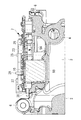
図1には、本発明の一実施形態の係るインバータ一体型電動圧縮機の主要部の斜視図が示され、図2には、そのa−a縦断面相当図、図3には、インバータ収容部に設置されるインバータ装置の分解斜視図、図4には、インバータ収容部を密閉する蓋体の裏面側斜視図、図5には、電源ケーブル単体の斜視図が示されている。
インバータ一体型電動圧縮機1は、外殻を構成する円筒状とされたハウジング2を備えている。ハウジング2は、電動モータ(図示省略)を内蔵するアルミダイカスト製のモータハウジング3と、圧縮機構(図示省略)を内蔵するアルミダイカスト製の圧縮機ハウジング(図示省略)とを一体に結合することにより構成されるものである。
An embodiment according to the present invention will be described below with reference to FIGS.
FIG. 1 is a perspective view of a main part of an inverter-integrated electric compressor according to an embodiment of the present invention. FIG. 2 is a vertical cross-sectional view corresponding to aa, and FIG. 4 is an exploded perspective view of the inverter device installed in the section, FIG. 4 is a rear perspective view of the lid that seals the inverter accommodating section, and FIG. 5 is a perspective view of the power cable alone.
The inverter-integrated electric compressor 1 includes a
インバータ一体型電動圧縮機1は、ハウジング2内に内蔵されている電動モータと圧縮機構とが回転軸を介して連結されており、電動モータが後述するインバータ装置7を介して回転駆動されることにより圧縮機構が駆動され、モータハウジング3の後端側面に設けられている吸入ポート4を介してその内部に吸込まれた低圧の冷媒ガスを、電動モータの周囲を経て吸込み、圧縮機構で高圧に圧縮して圧縮機ハウジング内に吐出した後、外部に送出する構成とされている。
In the inverter-integrated electric compressor 1, an electric motor built in the
モータハウジング3には、内周面側に軸線方向に沿って冷媒を流通させるための複数の冷媒流通路5が形成され、その外周部には、電動圧縮機1の据え付け用脚部6が複数箇所に設けられている。また、ハウジング2(モータハウジング3側)の外周部には、インバータ装置7を一体的に組み込むためのインバータ収容部8が一体に成形されている。このインバータ収容部8は、平面視が矩形形状とされており、底部がモータハウジング3の外周壁に沿う形状で、中央部に冷媒流通路5に対応した凸状の稜線部9Aが形成されるとともに、その両側部にハウジング外周壁に沿う凹部9Bが形成され、周囲にフランジ部10が立ち上げられた構成とされている。
The
このモータハウジング3には、圧縮機ハウジングが結合される前端側から後端側に向って抜き勾配が設けられており、また、内周側に設けられている冷媒流通路5が、吸入ポート4側から圧縮機構側に向って断面積が大きくされていることから、インバータ収容部8内の底面に形成される稜線部9A等も前方から後方に向って下向きに傾斜された構成とされている。
The
インバータ収容部8は、インバータ装置7が組み込まれた後、図4に示す蓋体11がフランジ部10に取り付けられることにより密閉される構成とされている。この蓋体11の内面側には、高電圧ケーブル(電源側ケーブル)12が設けられている。高電圧ケーブル12は、図5に示すように、一端側にコネクタ13が設けられ、他端側に電源側のケーブルと接続されるコネクタ端子14が設けられたものであり、一端のコネクタ13が、後述するメイン基板23上に設けられるP−N端子29と対応する位置において、蓋体11の内面にネジ15で固定設置され、他端のコネクタ端子14が、端子部分を蓋体11の外表面側に突出させた状態で外面側から複数のネジ16で固定設置される構成とされている。
The inverter
この高電圧ケーブル12は、電源側ケーブルの一部をなすものであり、電源側ケーブルを介して車両に搭載されている電源ユニットに接続され、その一端に設けられているコネクタ13が、インバータ装置7のメイン基板23上に設けられているP−N端子29に接続されることにより、電源ユニットから給電される高電圧の直流電力をインバータ装置7に入力するためのものである。
The
インバータ装置7は、公知の如く、車両に搭載されている電源ユニットから給電される高電圧の直流電力を、上位制御装置(ECU)からの指令に基づいて所要周波数の三相交流電力に変換して電動モータに印加し、電動モータを回転駆動するものであり、図1ないし図3に示されるように、ハウジング2の外周に設けられているインバータ収容部8に対して一体に組み込まれている。
As is well known, the
このインバータ装置7は、ノイズ除去用の公知のフィルタ回路17を構成するケース入りのコイル18およびコンデンサ19等の複数の高電圧系電装部品(以下、単に電装部品と称することもある。)と、直流電力を三相交流電力に変換する公知のスイッチング回路20を構成するIGBT等の発熱性パワートランジスタからなる複数(6個)の半導体スイッチング素子21と、フィルタ回路17およびスイッチング回路20を含むインバータ回路およびそれを制御するマイコン等を含む制御回路22が実装されている矩形状のメイン基板23と、上位制御装置と通信ハーネス24を介して接続される通信回路25が実装されてメイン基板23よりも小型のサブ基板26等とから構成されている。
The
なお、通信ハーネス24は、車両側の上位制御装置(ECU)とインバータ装置7側の通信回路25との間で制御信号を送受信する複数本の通信線と、制御回路22および通信回路25を動作させる低電圧(通常、12V)の電力を車載バッテリから供給する複数本の電源線とから構成されるものであり、後述の通りコネクタ34を介してサブ基板26に接続される構成とされている。
The
インバータ装置7は、公知のものでよいが、ここでは、メイン基板23として、フィルタ回路17を構成するコイル18およびコンデンサ19等の電装部品を、そのリード端子18A,19Aを半田付けすることによって実装し、また、スイッチング回路20を構成するIGBT等の発熱性パワートランジスタからなる複数(6個)の半導体スイッチング素子21を、そのリード端子21A(リード端子21Aは、IGBTが1個当たり3本有することから、合計18本となる。)を半田付けすることによって実装したものが用いられている。
The
つまり、メイン基板23は、フィルタ回路17を構成するコイル18およびコンデンサ19のリード端子18A,19A、並びにスイッチング回路20を構成する複数の半導体スイッチング素子21のリード端子21Aを、それぞれメイン基板23のスルーホールに貫通し、それを基板上のパターンに半田付けして実装することにより、メイン基板23上にフィルタ回路17およびスイッチング回路20を設けたものとされている。このメイン基板23は、矩形状でインバータ収容部8内に収納される大きさとされ、その4隅がインバータ収容部8の四隅に設けられているボス部27にネジ28を介して締め付け固定されるようになっている。
That is, the
フィルタ回路17を構成する高電圧系電装部品の1つであるコンデンサ19は、ケースに収容された構成とされており、図2および図3に示されるように、外形が角型形状(直方体形状)とされ、上面がフラットな平面形とされたものである。同様に、円筒状に巻かれたコイル18は、上面がフラットな平面形とされた半円筒形状のケースに収容された構成とされている。そして、これらのコイル18およびコンデンサ19は、矩形状とされたメイン基板23の一辺に沿って並設されるように実装されている。
A
このメイン基板23に実装されたコイル18およびコンデンサ19は、インバータ収容部8内でその底面を構成する円筒状ハウジング2の外周壁の軸線方向に沿う一側部の凹部9Bとされた底面上に接着剤を介して固定設置されることにより、各々のフラットな上面でメイン基板23の下面を支え、メイン基板23にかかる応力や振動を支持可能な構成とされている。また、コイル18およびコンデンサ19で下面が支持されたメイン基板23のコンデンサ19で支持されている部位の上面側に、高電圧ケーブル12のコネクタ13が接続されることにより、電源からの直流電力をインバータ装置7に入力するP−N端子29が上方に向けて立設された構成とされている。
The
また、複数(6個)の半導体スイッチング素子21は、図3に示されるように、インバータ収容部8内において、その底面を構成する円筒状ハウジング2の外周壁の軸線方向に沿う他側部の凹部9B上に立設された放熱ブロック30上に固定設置されている。放熱ブロック30は、熱伝導性材であるアルミ合金製の所定長さを有する直方体形状のブロック体であり、その左右両側の鉛直な側面に半導体スイッチング素子21が3個ずつ各3本のリード端子21Aを鉛直上方に向けてネジ止め固定されることにより、立体的に設置されている。この放熱ブロック30は、半導体スイッチング素子21での発熱をハウジング2側に放熱し、半導体スイッチング素子21を冷却する機能を担っている。
Further, as shown in FIG. 3, the plurality (six) of
複数(6個)の半導体スイッチング素子21の合計18本のリード端子21Aは、図1に示されるように、メイン基板23のコイル18およびコンデンサ19で支えられている一辺と対向する他辺側に沿って設けられているスルーホール23Aを貫通して上方に突出され、半田付けされることによりメイン基板23に実装されている。これによって、メイン基板23の上記一辺と対向する他辺側を、複数の半導体スイッチング素子21の多数のリード端子21Aを介して下方から支持可能な構成とされている。なお、この放熱ブロック30は、インバータ収容部8内の凹部9B上にネジ止め固定されているが、モータハウジング3側に一体成形した構成としてもよい。
As shown in FIG. 1, a total of 18
さらに、メイン基板23の下方部位において、インバータ収容部8の底面側の後方部位には、図3および図6に示されるように、凸状の稜線部9Aと接触しないように、通信回路25が実装されたサブ基板26が、モータハウジング3と一体成形されている3箇所のボス部31に固定ネジ32を介して締め付け固定されている。このサブ基板26は、メイン基板23に比較してかなり小さい小型の基板とされており、耐振性を考慮して前端側から後端側にかけて末広がり形状とされた略三角形状の基板とされ、その前端の1点と後端の2点の3箇所で上記の如く固定設置されている。
Further, in the lower part of the
サブ基板26は、インバータ収容部8の左右両側に配置されているフィルタ回路17用のコイル18およびコンデンサ19と、スイッチング回路20用の複数の半導体スイッチング素子21間のスペースに配設され、上方に配置されているメイン基板23との間の距離をできるだけ大きくして設置することが望ましい。このサブ基板26と、上方に配置されているメイン基板23とは、メイン基板23側の基板間接続端子33(図3を参照)をサブ基板26上の接続コネクタ35に接続することにより、電気的、機械的に互いに接続可能とされている。
The sub-board 26 is disposed in a space between the
また、サブ基板26には、図3および図6に示されるように、通信ハーネス24がコネクタ34を介して接続されており、そのコネクタ34の接続部がサブ基板26の固定ネジ32に接近した後端辺の一端側に配設され、他端側の固定ネジ32に接近して上部のメイン基板23との接続コネクタ35が配設された構成とされている。一方、通信ハーネス24は、インバータ収容部8のフランジ部10に設けられた切欠き部10Aに設置されたグロメット36を介してインバータ収容部8に貫通されており、そのグロメット36による固定部位から最短距離の位置でコネクタ34を介してサブ基板26に接続されている。
Further, as shown in FIGS. 3 and 6, the
インバータ装置7のスイッチング回路20を経て直流電力から三相交流電力に変換された電力は、メイン基板23からUVWバスバー37を介してガラス密封端子38に出力される構成とされている。ガラス密封端子38は、インバータ収容部8内の前方部位にモータハウジング3を貫通するように設けられた端子設置穴3A(図3参照)に設置され、UVWバスバー37からの三相交流電力をモータハウジング3内の電動モータに対して印加するものであり、このガラス密封端子38にメイン基板23上に設置されたUVWバスバー37が接続されている。
The power converted from the DC power to the three-phase AC power through the switching
次ぎに、通信ハーネス24の通信線および電源線を介して外部からインバータ装置7に入射される電磁ノイズおよびインバータ装置7のスイッチング回路20等で発生し、通信ハーネス24の通信線および電源線を介して外部に放射される電磁ノイズに対するイミュニティ性能の向上策について、図6および図7を参照して説明する。
通信ハーネス24が接続されるサブ基板26は、上述の如く、通信回路25が実装されたもので、メイン基板23から分割された小型の略三角形状とされた基板であり、該メイン基板23の下方部位に距離をおいて配置され、ハウジング2側の3箇所のボス部31に固定ネジ32を介して締め付け固定されている。
Next, electromagnetic noise incident on the
As described above, the sub-board 26 to which the
このサブ基板26上には、その後端辺の一端側を固定する固定ネジ32に近接して通信ハーネス24側のコネクタ34が配設され、また、他端側を固定する固定ネジ32に近接してメイン基板23に対する接続コネクタ35が配設されており、両コネクタ34,35間を結ぶように、基板の後端辺に沿って通信ライン39が配設されるとともに、他の1箇所の固定ネジ32の近傍を経由した三角ラインに沿って電源ライン40が配設された構成とされている。
On the sub-board 26, a
通信ライン39は、接続コネクタ35に近接する位置にサブ基板26のフレームグランド(GND)(図示省略)に繋がるように設けられているノイズ対策部品(例えば、ダイオード)41に接続されており、また、電源ライン40は、コネクタ34に近接する位置および他の1箇所の固定ネジ32に近接する位置において、サブ基板26のフレームグランド(GND)に繋がるように配設されている複数のノイズ対策部品(例えば、チップコンデンサ)42に接続されている。更に電源ライン40は、ノイズ対策部品42以外に、ライン上の途中位置でも、サブ基板26のフレームグランド(GND)に繋がるように設けられた複数のノイズ対策部品(例えば、チップコンデンサ)43と接続されている。
The
一方、サブ基板26のフレームグランド(GND)は、それぞれサブ基板26を締め付け固定している3箇所の固定ネジ32を介してハウジング2側に接地されており、サブ基板26上の通信ライン39および電源ライン40からノイズ対策部品41,42,43を介して除去された電磁ノイズは、フレームグランド(GND)、固定ネジ32およびハウジング2を介してアースされる構成とされている。
On the other hand, the frame ground (GND) of the sub-board 26 is grounded to the
つまり、通信ハーネス24を経て外部からサブ基板26に入射されたノイズは、通信ライン39および電源ライン40上を図6に示す矢印方向に流れるが、通信ライン39に接続されているノイズ対策部品41および電源ライン40に接続されているノイズ対策部品42,43によって除去され、接続コネクタ35を経てメイン基板23側の制御回路22等に入射するのを阻止することができる。
That is, noise incident on the sub-board 26 from the outside through the
また、インバータ装置7側のスイッチング回路20等で発生したノイズは、メイン基板23から基板間接続端子33、接続コネクタ35を経てサブ基板26に入り、通信ライン39および電源ライン40上を図7に示す矢印方向に流れ、通信ハーネス24を経て外部に放射されることになるが、該ノイズをサブ基板26の通信ライン39、電源ライン40上を流れる間に、各ライン39,40に接続されているノイズ対策部品41,42,43で除去することにより、外部への放射を阻止することができる。
Further, noise generated in the switching
以上に説明の構成により、本実施形態によれば、以下の作用効果を奏する。
ハウジング2のインバータ収容部8に一体に組み込まれたインバータ装置7は、電源ユニットから電源側ケーブル(高電圧ケーブル12等)を介して入力された高電圧の直流電力をスイッチング回路20により所要周波数の三相交流電力を変換し、UVWバスバー37およびガラス密封端子38を介して電動モータに印加することにより、電動圧縮機1を所要回転数で駆動し、冷媒の圧縮作用を行う。一方、インバータ装置7は、通信ハーネス24を経て上位制御装置(ECU)との間で入出力される制御信号により制御回路22を介して制御される。
With the configuration described above, according to the present embodiment, the following operational effects can be obtained.
The
この際、通信ハーネス24を構成する通信線および低電圧の電力線は、外部からの電磁ノイズを入射するあるいはインバータ装置7側で発生した電磁ノイズを外部に放射するアンテナとして機能することになり、そのノイズの入・放射が原因でインバータ装置7や他の搭載機器が誤動作を起こす虞がある。これを防止するため、かかる電磁ノイズに対する放射イミュニティ試験や入射イミュニティ試験において、各カーメーカが定めている基準を満たす必要がある。
At this time, the communication line and the low-voltage power line constituting the
しかるに、本実施形態では、インバータ回路基板をメイン基板23と、小型のサブ基板26とに分割し、サブ基板26をメイン基板23の下方部位に配置し、その小型化したサブ基板26を、通信回路25が実装され、通信線および電源線を含む通信ハーネス24がコネクタ34を介して接続されるとともに、メイン基板23と基板間接続端子33および接続コネクタ35を介して接続され、少なくとも3箇所以上の多角形配置点でハウジング2側に固定ネジ32で締め付け固定される基板であって、コネクタ34および接続コネクタ35が2箇所の固定ネジ32に近接配置され、そのコネクタ34,35間に、サブ基板26のフレームグランドに繋がるノイズ対策部品41と接続された通信ライン39が配設されるとともに、他の1箇所の固定ネジ32近傍を経由する三角ラインに沿って、フレームグランドに繋がるノイズ対策部品42,43と接続された電源ライン40が配設された基板とし、そのフレームグランドを、固定ネジ32を介してハウジング2側に接地した構成としている。
However, in the present embodiment, the inverter circuit board is divided into the
このため、通信回路25が実装され、通信ハーネス24と接続される基板をサブ基板26としてメイン基板23から分離し、そのサブ基板26上に配設される通信ライン39および電源ライン40に対して、各々フレームグランド(GND)に繋がるノイズ対策部品41,42,43を接続したことにより、通信ハーネス24を経て外部からインバータ装置7に入射するノイズをサブ基板26上で除去し、メイン基板23上の制御回路22に達しないようにすることができ、また、インバータ装置7のスイッチング回路20等で発生しノイズを、メイン基板23からサブ基板26を経て通信ハーネス24に至る間にサブ基板26上で除去することにより、通信ハーネス24を介して外部に放射しないようにすることができ、それらのノイズをサブ基板26のフレームグランド(GND)から固定ネジ32を介してハウジング2側に落とし、アースすることができる。
Therefore, the
これにより、通信ハーネス24の通信線および電源線を介して入射あるいは放射されるノイズを低減し、ノイズイミュニティ性能を向上させることができるとともに、サブ基板26上で全てのノイズ対策を採ることができることから、その構成をシンプルにし、より的確に電磁ノイズを除去することができる。また、サブ基板26をメイン基板23の下方部位でハウジング2により近い位置に一定の距離を保って配置しているため、互いのノイズ干渉を防止し、サブ基板26側のノイズ耐性をより強化することができ、しかもインバータ回路基板を2枚の基板23,26に分割したことにより、それぞれの基板面積を小型化し、耐振性を向上することができる。
As a result, noise that is incident or radiated through the communication line and the power supply line of the
また、サブ基板26が、略三角形状の基板とされ、その角部の3箇所で固定ネジ32によりハウジング2側に締め付け固定されているため、サブ基板26を極力小型化し、その幾何学的形状に沿って配設された通信ライン39および電源ライン40を流れるノイズを複数箇所の固定ネジ32に近接して配設されたノイズ対策部品41,42,43により除去し、そのノイズを各ノイズ対策部品41,42,43が繋がれているフレームグランド(GND)を経て近くの固定ネジ32からハウジング2側に落とし、アースすることができる。従って、小型化されたサブ基板26上において、ノイズ対策部品41,42,43の配置箇所とアース箇所を的確に確保し、ノイズ耐性をより強化することができる。
In addition, since the
さらに、本実施形態においては、通信ライン39が、接続コネクタ35付近に配設されたノイズ対策部品41を介して接続コネクタ35と近接する固定ネジ32にアース接続されており、また、電源ライン40が、通信ハーネス24が接続されるコネクタ34付近および他の1箇所の固定ネジ32付近に配設されたノイズ対策部品42を介してコネクタ34と近接する固定ネジ32および他の1箇所の固定ネジ32にアース接続された構成とされている。
Further, in the present embodiment, the
このため、サブ基板26上に配設されている通信ライン39および電源ライン40に対して、それぞれ適正位置にノイズ対策部品41,42を配設し、それらのノイズ対策部品41,42をサブ基板26のフレームグランド(GND)を介して最短位置の固定ネジ32にアース接続することにより、サブ基板26を経て入射あるいは放射されるノイズを除去し、速やかにハウジング2側にアースすることができ、これによって、ノイズ対策を容易化、的確化およびシンプル化し、各カーメーカから求められるノイズイミュニティ性能についても確実にクリアすることが可能となる。
For this reason,
また、本実施形態では、電源ライン40上において、固定ネジ32付近以外のライン上の途中位置にも少なくとも1個以上のノイズ対策部品43が設けられているため、三角ライン上に沿って配設される電源ライン40に対して、2箇所の固定ネジ32付近の間の途中位置に少なくとも1個以上のノイズ対策部品43を設けることにより、ノイズ対策部品43の数を増すことでノイズ除去性能を更に高めることができる。従って、電源ライン40側に対するノイズ耐性をより強化し、全体としてEMC特性を向上することができる。
Further, in the present embodiment, since at least one
なお、本発明は、上記実施形態にかかる発明に限定されるものではなく、その要旨を逸脱しない範囲において、適宜変形が可能である。例えば、上記実施形態においては、サブ基板26を略三角形状の小型化された基板としているが、必ずしも三角形状に限定されるものではなく、矩形、台形、その他の四辺形状とし、その4箇所の角部で固定ネジ32により締め付け固定するようにしてもよい。この場合でも、コネクタ34および接続コネクタ35を固定ネジ32近傍に配設し、通信ライン39および電源ライン40を上記実施形態と略同様に配設してノイズ除去対策を講ずることができる。
In addition, this invention is not limited to the invention concerning the said embodiment, In the range which does not deviate from the summary, it can change suitably. For example, in the above embodiment, the sub-board 26 is a substantially triangular downsized board. However, the board is not necessarily limited to a triangular shape, and has a rectangular shape, a trapezoidal shape, and other four-sided shapes. You may make it fix | tighten with the fixing
また、ノイズ対策部品41,42,43として、通信ライン39側にダイオード、電源ライン40側にチップコンデンサを例示したが、これに限定されるものではなく、同様の機能を有する他の部品であってもよいことはもちろんである。
Further, as the
1 インバータ一体型電動圧縮機
2 ハウジング
7 インバータ装置
8 インバータ収容部
23 メイン基板
24 通信ハーネス
25 通信回路
26 サブ基板
32 固定ネジ
34 コネクタ
35 接続コネクタ
39 通信ライン
40 電源ライン
41,42,43 ノイズ対策部品
DESCRIPTION OF SYMBOLS 1 Inverter integrated
Claims (6)
前記インバータ回路基板は、前記インバータ収容部内の上方部位に設置されるメイン基板と、その下方部位に設置される、前記メイン基板よりも小型のサブ基板とに分割され、
前記サブ基板は、通信回路が実装され、通信ハーネスがコネクタを介して接続されるとともに、前記メイン基板と接続コネクタを介して接続され、3箇所以上の多角形配置点で前記ハウジング側に固定ネジを介して締め付け固定される基板であって、
前記コネクタおよび前記接続コネクタが2箇所の前記固定ネジに近接配置され、そのコネクタ間に、該サブ基板のフレームグランドに繋がるノイズ対策部品と接続された通信ラインが配設されるとともに、他の1箇所の前記固定ネジ近傍を経由する三角ラインに沿って、前記フレームグランドに繋がるノイズ対策部品と接続された電源ラインが配設された基板とされ、
前記サブ基板の前記フレームグランドが、前記固定ネジを介して前記ハウジング側に接地された構成とされていることを特徴とするインバータ一体型電動圧縮機。 In the inverter-integrated electric compressor in which the inverter device including the inverter circuit board is integrally incorporated in the inverter accommodating portion of the housing,
The inverter circuit board is divided into a main board installed at an upper part in the inverter accommodating portion and a sub-board smaller than the main board installed at a lower part thereof,
The sub board is mounted with a communication circuit, a communication harness is connected via a connector, and is connected to the main board via a connection connector, and is fixed to the housing side at three or more polygonal arrangement points. A substrate that is fastened and fixed via
The connector and the connection connector are disposed in proximity to the two fixing screws, and a communication line connected to a noise countermeasure component connected to the frame ground of the sub-board is disposed between the connectors, and another 1 along the triangle line passing through the vicinity fixing screw locations, the frame ground leads to de-noise suppression parts and connected power line is a substrate which is arranged,
The inverter-integrated electric compressor, wherein the frame ground of the sub-board is grounded to the housing side through the fixing screw.
Priority Applications (5)
| Application Number | Priority Date | Filing Date | Title |
|---|---|---|---|
| JP2013128546A JP6180810B2 (en) | 2013-06-19 | 2013-06-19 | Inverter-integrated electric compressor |
| DE112014002913.0T DE112014002913B4 (en) | 2013-06-19 | 2014-05-19 | Electric compressor with integrated inverter |
| US14/787,173 US10186935B2 (en) | 2013-06-19 | 2014-05-19 | Inverter-integrated electric compressor |
| CN201480024572.1A CN105264229B (en) | 2013-06-19 | 2014-05-19 | Inverter-integrated electric compressor |
| PCT/JP2014/063165 WO2014203665A1 (en) | 2013-06-19 | 2014-05-19 | Inverter-integrated electric compressor |
Applications Claiming Priority (1)
| Application Number | Priority Date | Filing Date | Title |
|---|---|---|---|
| JP2013128546A JP6180810B2 (en) | 2013-06-19 | 2013-06-19 | Inverter-integrated electric compressor |
Publications (3)
| Publication Number | Publication Date |
|---|---|
| JP2015006028A JP2015006028A (en) | 2015-01-08 |
| JP2015006028A5 JP2015006028A5 (en) | 2016-06-30 |
| JP6180810B2 true JP6180810B2 (en) | 2017-08-16 |
Family
ID=52104407
Family Applications (1)
| Application Number | Title | Priority Date | Filing Date |
|---|---|---|---|
| JP2013128546A Active JP6180810B2 (en) | 2013-06-19 | 2013-06-19 | Inverter-integrated electric compressor |
Country Status (5)
| Country | Link |
|---|---|
| US (1) | US10186935B2 (en) |
| JP (1) | JP6180810B2 (en) |
| CN (1) | CN105264229B (en) |
| DE (1) | DE112014002913B4 (en) |
| WO (1) | WO2014203665A1 (en) |
Families Citing this family (11)
| Publication number | Priority date | Publication date | Assignee | Title |
|---|---|---|---|---|
| US10700471B2 (en) * | 2016-01-15 | 2020-06-30 | Embraco Indústria De Compressores E Soluções Em Refrigeração Ltda. | System, method and means for connecting and fixing an electronic control to an airtight compressor and an airtight compressor |
| CN206118217U (en) * | 2016-01-15 | 2017-04-19 | 惠而浦股份公司 | Electronic controller's electromagnetic interference filters ground terminal of circuit and ground connection that electromagnetic interference filtered circuit and airtight compressor |
| US10873247B2 (en) * | 2016-02-24 | 2020-12-22 | Denso Corporation | Electric compressor for vehicle, and method for manufacturing electric compressor for vehicle |
| JP6814607B2 (en) * | 2016-11-11 | 2021-01-20 | 三菱重工サーマルシステムズ株式会社 | Electric compressor |
| DE102017103197A1 (en) * | 2017-02-16 | 2018-08-16 | Schaeffler Technologies AG & Co. KG | Electronics housing for an E-axis drive and E-axis with electronics housing |
| DE102017111396B4 (en) * | 2017-05-24 | 2020-08-06 | Hanon Systems | Arrangement for the active suppression of interference signals |
| DE102018110354B3 (en) * | 2018-04-30 | 2019-10-31 | Hanon Systems | Electronic module of an inverter and method for its assembly |
| DE102018110361A1 (en) * | 2018-04-30 | 2019-10-31 | Hanon Systems | Mounting assembly with wired electronic power components and their assembly with a motor housing |
| JP7221607B2 (en) * | 2018-07-31 | 2023-02-14 | サンデン株式会社 | electric compressor |
| CN116134223A (en) * | 2020-09-24 | 2023-05-16 | 翰昂汽车零部件有限公司 | Air compressor |
| JP7540373B2 (en) * | 2021-03-18 | 2024-08-27 | 株式会社デンソー | Electronic Control Unit |
Family Cites Families (13)
| Publication number | Priority date | Publication date | Assignee | Title |
|---|---|---|---|---|
| CN100419263C (en) * | 2005-04-18 | 2008-09-17 | 三菱重工业株式会社 | Compressor having internally mounted inverter |
| JP5144945B2 (en) * | 2007-03-06 | 2013-02-13 | 三菱重工業株式会社 | Integrated electric compressor |
| JP5107013B2 (en) * | 2007-12-13 | 2012-12-26 | 三菱重工業株式会社 | Inverter-integrated electric compressor |
| JP5107114B2 (en) | 2008-03-28 | 2012-12-26 | 三菱重工業株式会社 | Inverter-integrated electric compressor |
| JP4657329B2 (en) | 2008-07-29 | 2011-03-23 | 日立オートモティブシステムズ株式会社 | Power converter and electric vehicle |
| JP5249795B2 (en) * | 2009-01-15 | 2013-07-31 | 三菱重工業株式会社 | Inverter-integrated electric compressor |
| JP5839769B2 (en) | 2009-03-06 | 2016-01-06 | 三菱重工業株式会社 | Inverter module and inverter-integrated electric compressor |
| JP5500973B2 (en) * | 2009-12-25 | 2014-05-21 | 日立オートモティブシステムズ株式会社 | Power converter |
| JP2011214432A (en) * | 2010-03-31 | 2011-10-27 | Denso Corp | Electric compressor |
| JP5574794B2 (en) * | 2010-04-14 | 2014-08-20 | 三菱重工業株式会社 | Inverter-integrated electric compressor |
| JP2011236858A (en) * | 2010-05-12 | 2011-11-24 | Valeo Japan Co Ltd | Earth connection structure of electric compressor |
| JP5766431B2 (en) | 2010-11-30 | 2015-08-19 | 三菱重工業株式会社 | Electric compressor |
| JP5522009B2 (en) * | 2010-12-02 | 2014-06-18 | 株式会社豊田自動織機 | Electric compressor |
-
2013
- 2013-06-19 JP JP2013128546A patent/JP6180810B2/en active Active
-
2014
- 2014-05-19 CN CN201480024572.1A patent/CN105264229B/en active Active
- 2014-05-19 US US14/787,173 patent/US10186935B2/en active Active
- 2014-05-19 DE DE112014002913.0T patent/DE112014002913B4/en active Active
- 2014-05-19 WO PCT/JP2014/063165 patent/WO2014203665A1/en active Application Filing
Also Published As
| Publication number | Publication date |
|---|---|
| JP2015006028A (en) | 2015-01-08 |
| US20160111942A1 (en) | 2016-04-21 |
| DE112014002913T5 (en) | 2016-03-03 |
| WO2014203665A1 (en) | 2014-12-24 |
| CN105264229B (en) | 2017-04-12 |
| DE112014002913B4 (en) | 2023-08-24 |
| CN105264229A (en) | 2016-01-20 |
| US10186935B2 (en) | 2019-01-22 |
Similar Documents
| Publication | Publication Date | Title |
|---|---|---|
| JP6180810B2 (en) | Inverter-integrated electric compressor | |
| US10008895B2 (en) | Inverter-integrated electric compressor | |
| JP5107114B2 (en) | Inverter-integrated electric compressor | |
| JP6173763B2 (en) | Inverter-integrated electric compressor | |
| JP6444605B2 (en) | Inverter-integrated electric compressor | |
| JP5582749B2 (en) | Inverter-integrated electric compressor | |
| JP5117843B2 (en) | Inverter-integrated electric compressor | |
| JP5221935B2 (en) | Inverter-integrated electric compressor | |
| US9115707B2 (en) | Inverter module and integrated-inverter electric compressor using the same | |
| JP5448797B2 (en) | Control board, inverter device, and inverter-integrated electric compressor | |
| JP2009114961A (en) | Electric compressor for on-vehicle air-conditioner | |
| US9929618B2 (en) | Inverter-integrated electric compressor | |
| CN108369863B (en) | Power conversion device | |
| JP5595461B2 (en) | Inverter-integrated electric compressor | |
| JP5536172B2 (en) | Inverter-integrated electric compressor | |
| JP2010144694A (en) | Inverter integrated electric compressor |
Legal Events
| Date | Code | Title | Description |
|---|---|---|---|
| A521 | Request for written amendment filed |
Free format text: JAPANESE INTERMEDIATE CODE: A523 Effective date: 20160517 |
|
| A621 | Written request for application examination |
Free format text: JAPANESE INTERMEDIATE CODE: A621 Effective date: 20160517 |
|
| A131 | Notification of reasons for refusal |
Free format text: JAPANESE INTERMEDIATE CODE: A131 Effective date: 20170404 |
|
| A521 | Request for written amendment filed |
Free format text: JAPANESE INTERMEDIATE CODE: A523 Effective date: 20170605 |
|
| TRDD | Decision of grant or rejection written | ||
| A01 | Written decision to grant a patent or to grant a registration (utility model) |
Free format text: JAPANESE INTERMEDIATE CODE: A01 Effective date: 20170620 |
|
| A61 | First payment of annual fees (during grant procedure) |
Free format text: JAPANESE INTERMEDIATE CODE: A61 Effective date: 20170719 |
|
| R150 | Certificate of patent or registration of utility model |
Ref document number: 6180810 Country of ref document: JP Free format text: JAPANESE INTERMEDIATE CODE: R150 |
|
| S111 | Request for change of ownership or part of ownership |
Free format text: JAPANESE INTERMEDIATE CODE: R313111 |
|
| R350 | Written notification of registration of transfer |
Free format text: JAPANESE INTERMEDIATE CODE: R350 |